EP3415888A1 - Sensor system and method - Google Patents
Sensor system and method Download PDFInfo
- Publication number
- EP3415888A1 EP3415888A1 EP18175715.4A EP18175715A EP3415888A1 EP 3415888 A1 EP3415888 A1 EP 3415888A1 EP 18175715 A EP18175715 A EP 18175715A EP 3415888 A1 EP3415888 A1 EP 3415888A1
- Authority
- EP
- European Patent Office
- Prior art keywords
- sensor
- bonding layer
- metallic
- metallic joint
- joint
- Prior art date
- Legal status (The legal status is an assumption and is not a legal conclusion. Google has not performed a legal analysis and makes no representation as to the accuracy of the status listed.)
- Granted
Links
Images

Classifications
-
- B—PERFORMING OPERATIONS; TRANSPORTING
- B23—MACHINE TOOLS; METAL-WORKING NOT OTHERWISE PROVIDED FOR
- B23K—SOLDERING OR UNSOLDERING; WELDING; CLADDING OR PLATING BY SOLDERING OR WELDING; CUTTING BY APPLYING HEAT LOCALLY, e.g. FLAME CUTTING; WORKING BY LASER BEAM
- B23K1/00—Soldering, e.g. brazing, or unsoldering
- B23K1/002—Soldering by means of induction heating
-
- G—PHYSICS
- G01—MEASURING; TESTING
- G01D—MEASURING NOT SPECIALLY ADAPTED FOR A SPECIFIC VARIABLE; ARRANGEMENTS FOR MEASURING TWO OR MORE VARIABLES NOT COVERED IN A SINGLE OTHER SUBCLASS; TARIFF METERING APPARATUS; MEASURING OR TESTING NOT OTHERWISE PROVIDED FOR
- G01D5/00—Mechanical means for transferring the output of a sensing member; Means for converting the output of a sensing member to another variable where the form or nature of the sensing member does not constrain the means for converting; Transducers not specially adapted for a specific variable
- G01D5/48—Mechanical means for transferring the output of a sensing member; Means for converting the output of a sensing member to another variable where the form or nature of the sensing member does not constrain the means for converting; Transducers not specially adapted for a specific variable using wave or particle radiation means
-
- G—PHYSICS
- G01—MEASURING; TESTING
- G01N—INVESTIGATING OR ANALYSING MATERIALS BY DETERMINING THEIR CHEMICAL OR PHYSICAL PROPERTIES
- G01N29/00—Investigating or analysing materials by the use of ultrasonic, sonic or infrasonic waves; Visualisation of the interior of objects by transmitting ultrasonic or sonic waves through the object
- G01N29/22—Details, e.g. general constructional or apparatus details
- G01N29/223—Supports, positioning or alignment in fixed situation
-
- G—PHYSICS
- G01—MEASURING; TESTING
- G01K—MEASURING TEMPERATURE; MEASURING QUANTITY OF HEAT; THERMALLY-SENSITIVE ELEMENTS NOT OTHERWISE PROVIDED FOR
- G01K11/00—Measuring temperature based upon physical or chemical changes not covered by groups G01K3/00, G01K5/00, G01K7/00 or G01K9/00
- G01K11/22—Measuring temperature based upon physical or chemical changes not covered by groups G01K3/00, G01K5/00, G01K7/00 or G01K9/00 using measurement of acoustic effects
- G01K11/26—Measuring temperature based upon physical or chemical changes not covered by groups G01K3/00, G01K5/00, G01K7/00 or G01K9/00 using measurement of acoustic effects of resonant frequencies
- G01K11/265—Measuring temperature based upon physical or chemical changes not covered by groups G01K3/00, G01K5/00, G01K7/00 or G01K9/00 using measurement of acoustic effects of resonant frequencies using surface acoustic wave [SAW]
-
- G—PHYSICS
- G01—MEASURING; TESTING
- G01L—MEASURING FORCE, STRESS, TORQUE, WORK, MECHANICAL POWER, MECHANICAL EFFICIENCY, OR FLUID PRESSURE
- G01L1/00—Measuring force or stress, in general
- G01L1/16—Measuring force or stress, in general using properties of piezoelectric devices
- G01L1/162—Measuring force or stress, in general using properties of piezoelectric devices using piezoelectric resonators
- G01L1/165—Measuring force or stress, in general using properties of piezoelectric devices using piezoelectric resonators with acoustic surface waves
-
- G—PHYSICS
- G01—MEASURING; TESTING
- G01L—MEASURING FORCE, STRESS, TORQUE, WORK, MECHANICAL POWER, MECHANICAL EFFICIENCY, OR FLUID PRESSURE
- G01L19/00—Details of, or accessories for, apparatus for measuring steady or quasi-steady pressure of a fluent medium insofar as such details or accessories are not special to particular types of pressure gauges
- G01L19/14—Housings
- G01L19/147—Details about the mounting of the sensor to support or covering means
-
- G—PHYSICS
- G01—MEASURING; TESTING
- G01L—MEASURING FORCE, STRESS, TORQUE, WORK, MECHANICAL POWER, MECHANICAL EFFICIENCY, OR FLUID PRESSURE
- G01L3/00—Measuring torque, work, mechanical power, or mechanical efficiency, in general
-
- G—PHYSICS
- G01—MEASURING; TESTING
- G01N—INVESTIGATING OR ANALYSING MATERIALS BY DETERMINING THEIR CHEMICAL OR PHYSICAL PROPERTIES
- G01N29/00—Investigating or analysing materials by the use of ultrasonic, sonic or infrasonic waves; Visualisation of the interior of objects by transmitting ultrasonic or sonic waves through the object
- G01N29/22—Details, e.g. general constructional or apparatus details
- G01N29/24—Probes
- G01N29/2462—Probes with waveguides, e.g. SAW devices
Definitions
- the subject matter described herein relates to sensors.
- SAW surface acoustic wave
- the SAW devices may be wafer level hermetically capped or placed and sealed inside of hermetic discrete packages, and then mounted onto structures in order to sense data of the structure.
- the SAW devices may be mounted onto structures such as shafts, rods, blades, or alternative structures used in various applications such as aviation, oil and gas, transportation, renewable energy extraction, or the like.
- the processes of mounting sensors to structures presently include several issues.
- One issue present with mounting sensors to certain structures is that many structures are too large to fit into conventional ovens or reflow equipment or may not be able to be transported to a location having conventional ovens or reflow equipment to mount the sensors to the structure. Therefore, many SAW devices are mounted to structures using an adhesive or epoxy material.
- using an epoxy or adhesive to mount a sensor to a structure limits the operating temperature of the system, reduces the sensitivity of the sensor to sense data of the structure, limits the capability of future re-workability of the sensors mounted to the structures, and requires significant time for the epoxy or adhesive to properly cure, which increases associated manufacturing and material costs. It is advantageous to have a more robust mounting method to attach these sensors both in the field and in a production setting.
- a system in one embodiment, includes a structure configured to have a structure bonding layer disposed on a surface of the structure.
- the structure bonding layer is a metallic alloy.
- the system includes a sensor configured to have a sensor bonding layer disposed on a surface of the sensor.
- the sensor bonding layer is a metallic alloy.
- the sensor bonding layer is configured to be coupled to the structure bonding layer via a metallic joint in order for the sensor to sense data of the structure through the metallic joint, the structure bonding layer, and the sensor bonding layer.
- a method includes disposing a structure bonding layer on a surface of a structure.
- the structure bonding layer is a metallic alloy.
- the method includes disposing a sensor bonding layer on a surface of a sensor.
- the sensor bonding layer is a metallic alloy.
- the structure bonding layer is coupled to the sensor bonding layer via a metallic joint in order for the sensor to sense data of the structure through the metallic joint, the structure bonding layer, and the sensor bonding layer.
- a system in one embodiment, includes a structure configured to have a structure bonding layer disposed on a surface of the structure.
- the structure bonding layer is a metallic alloy.
- the system includes a sensor configured to have a sensor bonding layer disposed on a surface of the sensor.
- the sensor bonding layer is a metallic alloy.
- the sensor bonding layer is configured to be coupled to the structure bonding layer via a metallic joint at a location outside of a reflow oven in order for the sensor to sense data of the structure through the metallic joint, the structure bonding layer, and the sensor bonding layer.
- One or more embodiments of the inventive subject matter described herein provide for systems and methods having a sensor that is disposed on a structure via a metallic sensor bonding layer and a metallic structure bonding layer joined to a metallic joint in order to sense data of the structure through the metallic joint, the sensor bonding layer, and the structure bonding layer.
- the structures may be a large structure such as rods, shafts, blades, or the like, used in applications such as aviation, oil and gas, transportation, renewable energy extraction, power and energy systems, or the like.
- the sensor may sense temperature data, strain data, stress data, or the like or combinations thereof, of the structure.
- the senor may sense temperature data of a conduit that transfers oil, may sense the temperature of the oil that is transferred inside of the conduit, may sense the strain of a rotating shaft, or the like.
- the systems and methods described herein improves sensor sensitivity, enables exposure of systems to higher operating temperatures, and reduces an amount of creep of the bonding materials relative to systems that do not have a metallic bond.
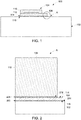
- Figure 1 illustrates a cross-sectional view of a system 100 in accordance with one embodiment.
- the system 100 includes a sensor 104 that is coupled to a structure 102.
- the structure 102 may be a shaft, a plate, a blade, a rod, or the like.
- the structure 102 may be a manufactured out of a metallic and/or non-metallic material.
- the structure 102 may be a steel shaft used to transfer oil or gas, may be an aluminum rotor blade of a wind turbine, may be a steel rotating or stationary shaft of an aerial device, or the like.
- the structure 102 may be any alternative component used in applications such as aviation, oil and gas, transportation, renewable energy extraction, power and energy systems, or the like.
- the sensor 104 has a first component 110 that is bonded to a second component 112.
- the first and second components 110, 112 of the sensor 104 may be single crystal quartz wafers that are coupled together by a liquid crystal polymer (LCP) material.
- the sensor 104 may have more than two or less than two components.
- the components of the sensor 104 may be held together by any alternative material.
- the sensor 104 may be a SAW device, or any alternative sensor that is used to sense data.
- the sensor 104 may be a SAW device that includes a strain gauge, torque sensor, temperature sensor, or the like, that is used to sense temperature data, strain data, stress data, or the like, of the structure 102.
- the sensor 104 may be any alternative sensor that senses (e.g., records, collects, reads, measures, or the like) information about the structure 102.
- the sensor 104 is coupled to a first side 114 of a metallic joint 106 of the system 100. Additionally, the structure 102 is coupled to an opposite, second side 116 of the metallic joint 106. The sensor 104 is operably coupled to the structure 102 via the metallic joint 106 in order to sense data of the structure.
- a surface of the sensor 104 that is coupled to the first side 114 of the metallic joint 106 and a surface of the structure 102 that is coupled to the second side 116 of the metallic joint 106 are planar or substantially planar surfaces (within manufacturing tolerances).
- one or more of the sensor 104 or the structure 102 may have nonplanar surfaces that are coupled to the metallic joint 106.
- the structure 102 may be a shaft that has a cross-sectional shape that is generally circular and the sensor 104 is operably coupled to the circular cross-sectional shape of the outer surface of the shaft structure 102.
- the structure 102 may be a blade with a curved outer surface and the sensor 104 is operably coupled to the curved outer surface of the blade structure 102.
- the system 100 includes a structure 102 having multiple sensors 104 that are operably coupled with the structure 102 via a metallic joint 106.
- the multiple sensors 104 may be arranged as an array of multiple sensors 104 in columns and rows or may be randomly arranged and coupled with one or more surfaces of the structure 102.
- the system 100 may have one or more metallic joints 106 that couple the sensors 104 with the structure 102.
- a single metallic joint 106 may couple multiple sensors 104 with the structure 102, multiple metallic joints 106 may couple the multiple sensors 104 with the structure 102, or the like.
- Figure 2 illustrates a partial cross-sectional view A of the system 100 of Figure 1 including the sensor 104 that is made of a quartz/non-metallic material in accordance with one embodiment.
- the sensor 104 has a sensor bonding layer 204 that is disposed on a surface 212 of the sensor 104.
- the sensor bonding layer 204 is a metallic alloy that can be coupled to the metallic joint 106.
- the sensor bonding layer 204 may be a layer of titanium, copper, silver, tin, nickel, gold, electroless nickel immersion gold (eNIG), or the like, that is disposed on the surface 212 of the sensor 104.
- the sensor bonding layer 204 may be any metallic compound and/or metal alloy that may be bonded to the metallic joint 106 and that provides adhesion between the sensor 104 and the structure 102.
- the sensor bonding layer 204 may be a metallic alloy that has a higher operating temperature and a higher modulus of elasticity relative to an epoxy, adhesive, liquid crystal polymer, or the like.
- the sensor 104 may be manufactured of a metallic material.
- the system 100 may be devoid of the sensor bonding layer 204 and the metallic sensor 104 may be coupled to the metallic joint 106.
- the structure 102 has a structure bonding layer 202 that is disposed on a surface 214 of the structure 102.
- the surface 214 may be an outer, or exterior surface of the structure 102 that is metallic and allows for metallic bonding between the structure and the metallic joint 106.
- the surface 214 may be an interior surface of a structure 102.
- the sensor 104 may be bonded to the interior of the structure 102 (e.g., the interior of a hollow shaft, or the like) and the structure bonding layer 202 may be disposed on an interior surface 214 of the structure 102.
- the structure bonding layer 202 is a metallic alloy that can be coupled to the metallic joint 106.
- the structure bonding layer 202 may be electroless nickel immersion gold (eNIG), electrolytic nickel gold (NiAu), or the like, when there cannot be a direct metallic bond between a non-metallic structure 102 and the sensor 104, or when the structure 102 and/or the sensor 104 are made of materials that are not applicable for metallic bonding and/or wetting.
- the structure bonding layer 202 may be any metallic compound and/or metallic alloy that may be bonded to the metallic joint 106.
- the structure bonding layer 202 may be a local metallization of the surface 214 of the structure 102.
- the structure 102 may be manufactured out of a material that may be able to be soldered to the second side 116 of the metallic joint 106 (e.g., the structure 102 may be manufactured out of a steel alloy).
- the structure bonding layer 202 may be a layer of a material suitable for metallic bonding that is disposed on the surface 214 of the structure 102.
- the structure 102 may be manufactured out of a material that may not be able to be soldered to the second side 116 of the metallic joint 106 (e.g., the structure 102 may be manufactured out of a brass alloy, a non-steel alloy, or the like).
- the structure bonding layer 202 may be a metallic alloy that has a higher operating temperature and a higher modulus of elasticity relative to an epoxy, adhesive, liquid crystal polymer, or the like.
- the metallic joint 106 is a metallic bond that operably couples the sensor 104 with the structure 102.
- the material of the metallic joint 106 include solder alloys (by percent weight) 96.5% tin - 3% silver - 0.5% copper; 80% gold - 20% tin; 92.5% lead - 5% tin - 2.5% silver; 88% gold - 12% germanium; or 82% gold - 18% indium.
- the metallic joint 106 may be any alternative materials and/or alloys. Non-limiting examples may include transient liquid phase sintering, sintered silver, sintered copper, sintered nickel, braze alloys, or the like.
- the sensor bonding layer 204 is coupled to the first side 114 of the metallic joint 106, and the structure bonding layer 202 is coupled to the second side 116 of the metallic joint 106 in order to operably couple the sensor 104 with the structure 102.
- the sensor 104 senses data of the structure 102 through the metallic joint 106, the sensor bonding layer 204 and the structure bonding layer 202.
- the sensor 104 may sense temperature, strain, stress, pressure, or the like, of the structure 102. For example, a torque may be applied to the structure 102.
- the sensor 104 may measure the stress or strain on the structure 102 that is transferred through the structure bonding layer 202, the metallic joint 106, and the sensor bonding layer 204 to the sensor 104.
- the modulus of elasticity of the material of the sensor bonding layer 204 and the modulus of elasticity of the material of the structure bonding layer 202 impacts the amount of strain data that is transferred from the structure 102 through the structure bonding layer 202, the metallic joint 106, and the sensor bonding layer 204 to the sensor 104.
- the modulus of elasticity of the material of the sensor and structure bonding layers 204, 202 increases (e.g., the materials become more stiff), the accuracy of the sensor 104 measuring strain data of the structure increases.
- the modulus of elasticity of the material of the sensor and structure bonding layers 204, 202 decreases (e.g., the materials become less stiff)
- the accuracy of the sensor 104 measuring strain data of the structure decreases.
- the modulus of elasticity in the bonding layers 204, 202 may have a minimum value of 700MPa.
- it is advantageous to have a modulus of elasticity include and above 2000MPa.
- the modulus of elasticity at varying temperatures may impact the accuracy of the strain data that is transferred to the sensor 104.
- Non-limiting metals, metal alloys, and/or metallic materials disclosed have sufficient modulus of elasticity at high temperatures. For example, in conventional epoxy materials, the modulus decreases at temperatures greater than 150°C. Alternatively, metals and/or metal alloys can be used between 40% to 75% of the homologous temperature with minimal creep. In the alloys listed, the homologous temperature may have a temperature greater than 1000°C.
- a sensor bonding layer 204 is disposed on a surface 212 of a sensor 104.
- the sensor bonding layer 204 may be a layer of a metallic material.
- the structure bonding layer 202 and the sensor bonding layer 204 may be a common or unique metallic alloys.
- the sensor bonding layer 204 may have a surface area that is substantially equivalent to a surface area of the surface 212 of the sensor 104, may have a surface area that is less than the surface area of the surface 212, or may have a surface area that is greater than the surface area of the surface 212.
- the sensor bonding layer 204 may extend an area that is substantially equivalent to, is less then, or is greater than the surface area of the metallic joint 106.
- the sensor bonding layer 204 and/or the structure bonding layer 202 use self-orientation or self-alignment to assemble the sensor 104 to the structure 102 via the metallic joint 106.
- the metallic joint 106 may be a solder layer made of a solder alloy having wetting properties that enables the sensor bonding layer 204 of the sensor 104 to self-align with the structure bonding layer 202 of the structure 102 when the sensor 104 is bonded to the structure 102.
- the metallic joint 106 allows the sensor 104 to self-align with the structure 102 without the use of additional pick-and-place equipment, additional fixture equipment, or the like.
- the structure bonding layer 202 is coupled to the sensor bonding layer 204 via the metallic joint 106.
- the sensor bonding layer 204 is coupled with a first side 114 of the metallic joint 106
- the structure bonding layer 202 is coupled with an opposite, second side 116 of the metallic joint 106.
- the sensor 104 is operably coupled with the structure 102 via the metallic joint 106 at a location outside of a conventional reflow oven.
- the structure 102 may be part of an assembly that may not be able to be transferred to a reflow oven, the structure 102 may not be able to be disassembled from the assembly to be transferred to a reflow oven, the structure 102 may not be able to fit inside of a reflow oven, the structure 102 may be manufacture out of a material that cannot withstand conventional operating temperatures of a conventional reflow oven, or the like.
- the sensor 104 is operably coupled with the structure 102 via the metallic joint 106 by an induction coil 402 that applies electrical stimuli to the metallic joint 106.
- the sensor 104 may be held in a position (e.g., by a fixture, by an operator, or the like) and the induction coil 402 may be placed in contact with, close by to, around, or the like, the sensor 104 and the substrate 102 to which the sensor 104 is to be bonded to.
- the induction coil 402 may be wrapped around the system 100, as illustrated in Figure 4 . Additionally or alternatively, the induction coil 402 may be wrapped around the sensor 104 such that the induction coil 402 is substantially parallel to the substrate 102.
- the induction coil 402 may be placed in contact with the system 100 by an alternative configuration.
- the induction coil 402 applies localized electrical stimuli to the metallic joint 106 to activate reflow the metallic joint 106 in order to operably couple the sensor 104 with the structure 102.
- the sensor 104 is operably coupled with the structure 102 via the metallic joint 106 by an active reflow process at the metallic joint 106.
- an exothermic metallic film such as a Reactive Nano Technologies (RNT) film 502, or an alternative material, may be placed within the metallic joint 106 in order to locally reflow the metallic joint 106.
- the sensor 104 may be held in a position (e.g., by a fixture, by an operator, or the like). Electrical stimuli that is applied to the film 502 by a fixture, an electrical source, or the like, activates reflow of the metallic joint 106 in order to operably couple the sensor 104 with the structure 102.
- the sensor 104 senses data of the structure 102 through the structure bonding layer 202, the metallic joint 106, and the sensor bonding layer 204.
- the sensor 104 may sense (e.g., collect, read, measure, obtain, or the like) data of the structure 102.
- the sensed data of the structure 102 transfers from the structure 102, through the metallic joint 106, through the metallic structure bonding layer and sensor bonding layer, to the sensor 104.
- the transfer of the sensed strain data of the structure 102 improves relative to a non-metallic sensor bonding layer 204 and non-metallic structure bonding layer 202.
- a system in one embodiment, includes a structure configured to have a structure bonding layer disposed on a surface of the structure.
- the structure bonding layer is a metallic alloy.
- the system includes a sensor configured to have a sensor bonding layer disposed on a surface of the sensor.
- the sensor bonding layer is a metallic alloy.
- the sensor bonding layer is configured to be coupled to the structure bonding layer via a metallic joint in order for the sensor to sense data of the structure through the metallic joint, the structure bonding layer, and the sensor bonding layer.
- the sensor bonding layer is configured to be coupled to the structure bonding layer via the metallic joint at a location outside of a reflow over.
- the data of the structure includes one or more of temperature data, stress data, or strain data.
- the structure is one or more of a shaft, a rod, or a blade.
- the senor is configured to self-align with the structure via the metallic joint.
- the structure bonding layer is configured to be disposed on an outer surface of the structure.
- the system includes an induction coil configured to be in operational contact with the metallic joint.
- the induction coil is configured to apply electrical stimuli to the metallic joint.
- the senor is a surface acoustic wave (SAW) device.
- SAW surface acoustic wave
- the SAW device comprises one or more of a strain gauge, a torque sensor, or a temperature sensor.
- a method includes disposing a structure bonding layer on a surface of a structure.
- the structure bonding layer is a metallic alloy.
- the method includes disposing a sensor bonding layer on a surface of a sensor.
- the sensor bonding layer is a metallic alloy.
- the structure bonding layer is coupled to the sensor bonding layer via a metallic joint in order for the sensor to sense data of the structure through the metallic joint, the structure bonding layer, and the sensor bonding layer.
- coupling the sensor bonding layer to the structure bonding layer via the metallic joint occurs at a location that is outside of a reflow over.
- the data of the structure includes one or more of temperature data, stress data, or strain data.
- the structure is one or more of a shaft, a rod, or a blade.
- the senor is configured to self-align with the structure via the metallic joint.
- the structure bonding layer is configured to be disposed on an outer surface of the structure.
- the senor is a surface acoustic wave (SAW) device.
- SAW surface acoustic wave
- the SAW device comprises one or more of a strain gauge, a torque sensor, or a temperature sensor.
- a system in one embodiment, includes a structure configured to have a structure bonding layer disposed on a surface of the structure.
- the structure bonding layer is a metallic alloy.
- the system includes a sensor configured to have a sensor bonding layer disposed on a surface of the sensor.
- the sensor bonding layer is a metallic alloy.
- the sensor bonding layer is configured to be coupled to the structure bonding layer via a metallic joint at a location outside of a reflow oven in order for the sensor to sense data of the structure through the metallic joint, the structure bonding layer, and the sensor bonding layer.
- the senor is a surface acoustic wave (SAW) device.
- SAW surface acoustic wave
- system may include hardware and/or software that operate(s) to perform one or more functions.
- a system or controller may include a computer processor or other logic-based device that performs operations based on instructions stored on a tangible and non-transitory computer readable storage medium, such as a computer memory.
- a system or controller may include a hard-wired device that performs operations based on hard-wired logic of the device.
- the systems and controllers shown in the figures may represent the hardware that operates based on software or hardwired instructions, the software that directs hardware to perform the operations, or a combination thereof.
- operably connected indicates that two or more components are connected in a manner that enables or allows at least one of the components to carry out a designated function.
- connections electrical and/or wireless connections
- one or more connections may exist that allow the components to communicate with each other, that allow one component to control another component, that allow each component to control the other component, and/or that enable at least one of the components to operate in a designated manner.
Landscapes
- Physics & Mathematics (AREA)
- General Physics & Mathematics (AREA)
- Chemical & Material Sciences (AREA)
- Analytical Chemistry (AREA)
- Acoustics & Sound (AREA)
- General Health & Medical Sciences (AREA)
- Life Sciences & Earth Sciences (AREA)
- Health & Medical Sciences (AREA)
- Biochemistry (AREA)
- Immunology (AREA)
- Pathology (AREA)
- Mechanical Engineering (AREA)
- Engineering & Computer Science (AREA)
- Arrangements For Transmission Of Measured Signals (AREA)
Abstract
Description
- The subject matter described herein relates to sensors.
- Sensors may be used in a variety of applications. For example, in electromechanical systems, surface acoustic wave (SAW) devices may be used as sensors to measure torque, temperature, pressure, and other parameters. The SAW devices may be wafer level hermetically capped or placed and sealed inside of hermetic discrete packages, and then mounted onto structures in order to sense data of the structure. The SAW devices may be mounted onto structures such as shafts, rods, blades, or alternative structures used in various applications such as aviation, oil and gas, transportation, renewable energy extraction, or the like.
- The processes of mounting sensors to structures presently include several issues. One issue present with mounting sensors to certain structures is that many structures are too large to fit into conventional ovens or reflow equipment or may not be able to be transported to a location having conventional ovens or reflow equipment to mount the sensors to the structure. Therefore, many SAW devices are mounted to structures using an adhesive or epoxy material. However, using an epoxy or adhesive to mount a sensor to a structure limits the operating temperature of the system, reduces the sensitivity of the sensor to sense data of the structure, limits the capability of future re-workability of the sensors mounted to the structures, and requires significant time for the epoxy or adhesive to properly cure, which increases associated manufacturing and material costs. It is advantageous to have a more robust mounting method to attach these sensors both in the field and in a production setting.
- In one embodiment, a system includes a structure configured to have a structure bonding layer disposed on a surface of the structure. The structure bonding layer is a metallic alloy. The system includes a sensor configured to have a sensor bonding layer disposed on a surface of the sensor. The sensor bonding layer is a metallic alloy. The sensor bonding layer is configured to be coupled to the structure bonding layer via a metallic joint in order for the sensor to sense data of the structure through the metallic joint, the structure bonding layer, and the sensor bonding layer.
- In one embodiment, a method includes disposing a structure bonding layer on a surface of a structure. The structure bonding layer is a metallic alloy. The method includes disposing a sensor bonding layer on a surface of a sensor. The sensor bonding layer is a metallic alloy. The structure bonding layer is coupled to the sensor bonding layer via a metallic joint in order for the sensor to sense data of the structure through the metallic joint, the structure bonding layer, and the sensor bonding layer.
- In one embodiment, a system includes a structure configured to have a structure bonding layer disposed on a surface of the structure. The structure bonding layer is a metallic alloy. The system includes a sensor configured to have a sensor bonding layer disposed on a surface of the sensor. The sensor bonding layer is a metallic alloy. The sensor bonding layer is configured to be coupled to the structure bonding layer via a metallic joint at a location outside of a reflow oven in order for the sensor to sense data of the structure through the metallic joint, the structure bonding layer, and the sensor bonding layer.
- The inventive subject matter will be better understood from reading the following description of non-limiting embodiments, with reference to the attached drawings, wherein below:
-
Figure 1 illustrates a cross-sectional view of a system in accordance with one embodiment; -
Figure 2 illustrates a partial cross-sectional view of the system ofFigure 1 in accordance with one embodiment; -
Figure 3 illustrates a method flowchart in accordance with one embodiment; -
Figure 4 illustrates a cross-sectional view of a system in accordance with one embodiment; and -
Figure 5 illustrates a cross-sectional view of a system in accordance with one embodiment. - One or more embodiments of the inventive subject matter described herein provide for systems and methods having a sensor that is disposed on a structure via a metallic sensor bonding layer and a metallic structure bonding layer joined to a metallic joint in order to sense data of the structure through the metallic joint, the sensor bonding layer, and the structure bonding layer. The structures may be a large structure such as rods, shafts, blades, or the like, used in applications such as aviation, oil and gas, transportation, renewable energy extraction, power and energy systems, or the like. The sensor may sense temperature data, strain data, stress data, or the like or combinations thereof, of the structure. For example, the sensor may sense temperature data of a conduit that transfers oil, may sense the temperature of the oil that is transferred inside of the conduit, may sense the strain of a rotating shaft, or the like. The systems and methods described herein improves sensor sensitivity, enables exposure of systems to higher operating temperatures, and reduces an amount of creep of the bonding materials relative to systems that do not have a metallic bond.
-
Figure 1 illustrates a cross-sectional view of asystem 100 in accordance with one embodiment. Thesystem 100 includes asensor 104 that is coupled to astructure 102. Thestructure 102 may be a shaft, a plate, a blade, a rod, or the like. Thestructure 102 may be a manufactured out of a metallic and/or non-metallic material. For example, thestructure 102 may be a steel shaft used to transfer oil or gas, may be an aluminum rotor blade of a wind turbine, may be a steel rotating or stationary shaft of an aerial device, or the like. Optionally, thestructure 102 may be any alternative component used in applications such as aviation, oil and gas, transportation, renewable energy extraction, power and energy systems, or the like. - The
sensor 104 has afirst component 110 that is bonded to asecond component 112. The first andsecond components sensor 104 may be single crystal quartz wafers that are coupled together by a liquid crystal polymer (LCP) material. Optionally, thesensor 104 may have more than two or less than two components. Optionally, the components of thesensor 104 may be held together by any alternative material. Thesensor 104 may be a SAW device, or any alternative sensor that is used to sense data. For example, thesensor 104 may be a SAW device that includes a strain gauge, torque sensor, temperature sensor, or the like, that is used to sense temperature data, strain data, stress data, or the like, of thestructure 102. Optionally, thesensor 104 may be any alternative sensor that senses (e.g., records, collects, reads, measures, or the like) information about thestructure 102. - The
sensor 104 is coupled to afirst side 114 of ametallic joint 106 of thesystem 100. Additionally, thestructure 102 is coupled to an opposite,second side 116 of themetallic joint 106. Thesensor 104 is operably coupled to thestructure 102 via themetallic joint 106 in order to sense data of the structure. In the illustrated embodiment ofFigure 1 , a surface of thesensor 104 that is coupled to thefirst side 114 of themetallic joint 106 and a surface of thestructure 102 that is coupled to thesecond side 116 of themetallic joint 106 are planar or substantially planar surfaces (within manufacturing tolerances). Optionally, one or more of thesensor 104 or thestructure 102 may have nonplanar surfaces that are coupled to themetallic joint 106. For example, thestructure 102 may be a shaft that has a cross-sectional shape that is generally circular and thesensor 104 is operably coupled to the circular cross-sectional shape of the outer surface of theshaft structure 102. Optionally, thestructure 102 may be a blade with a curved outer surface and thesensor 104 is operably coupled to the curved outer surface of theblade structure 102. - In one embodiment, the
system 100 includes astructure 102 havingmultiple sensors 104 that are operably coupled with thestructure 102 via ametallic joint 106. For example, themultiple sensors 104 may be arranged as an array ofmultiple sensors 104 in columns and rows or may be randomly arranged and coupled with one or more surfaces of thestructure 102. Optionally, thesystem 100 may have one or moremetallic joints 106 that couple thesensors 104 with thestructure 102. For example, a singlemetallic joint 106 may couplemultiple sensors 104 with thestructure 102, multiplemetallic joints 106 may couple themultiple sensors 104 with thestructure 102, or the like. -
Figure 2 illustrates a partial cross-sectional view A of thesystem 100 ofFigure 1 including thesensor 104 that is made of a quartz/non-metallic material in accordance with one embodiment. Thesensor 104 has asensor bonding layer 204 that is disposed on asurface 212 of thesensor 104. Thesensor bonding layer 204 is a metallic alloy that can be coupled to the metallic joint 106. For example, thesensor bonding layer 204 may be a layer of titanium, copper, silver, tin, nickel, gold, electroless nickel immersion gold (eNIG), or the like, that is disposed on thesurface 212 of thesensor 104. Optionally, thesensor bonding layer 204 may be any metallic compound and/or metal alloy that may be bonded to the metallic joint 106 and that provides adhesion between thesensor 104 and thestructure 102. Thesensor bonding layer 204 may be a metallic alloy that has a higher operating temperature and a higher modulus of elasticity relative to an epoxy, adhesive, liquid crystal polymer, or the like. Additionally or alternatively, thesensor 104 may be manufactured of a metallic material. For example, thesystem 100 may be devoid of thesensor bonding layer 204 and themetallic sensor 104 may be coupled to the metallic joint 106. - The
structure 102 has astructure bonding layer 202 that is disposed on asurface 214 of thestructure 102. In one embodiment, thesurface 214 may be an outer, or exterior surface of thestructure 102 that is metallic and allows for metallic bonding between the structure and the metallic joint 106. Optionally, thesurface 214 may be an interior surface of astructure 102. For example, thesensor 104 may be bonded to the interior of the structure 102 (e.g., the interior of a hollow shaft, or the like) and thestructure bonding layer 202 may be disposed on aninterior surface 214 of thestructure 102. - The
structure bonding layer 202 is a metallic alloy that can be coupled to the metallic joint 106. For example, thestructure bonding layer 202 may be electroless nickel immersion gold (eNIG), electrolytic nickel gold (NiAu), or the like, when there cannot be a direct metallic bond between anon-metallic structure 102 and thesensor 104, or when thestructure 102 and/or thesensor 104 are made of materials that are not applicable for metallic bonding and/or wetting. Optionally, thestructure bonding layer 202 may be any metallic compound and/or metallic alloy that may be bonded to the metallic joint 106. In one or more embodiments, thestructure bonding layer 202 may be a local metallization of thesurface 214 of thestructure 102. For example, thestructure 102 may be manufactured out of a material that may be able to be soldered to thesecond side 116 of the metallic joint 106 (e.g., thestructure 102 may be manufactured out of a steel alloy). Optionally, thestructure bonding layer 202 may be a layer of a material suitable for metallic bonding that is disposed on thesurface 214 of thestructure 102. For example, thestructure 102 may be manufactured out of a material that may not be able to be soldered to thesecond side 116 of the metallic joint 106 (e.g., thestructure 102 may be manufactured out of a brass alloy, a non-steel alloy, or the like). Thestructure bonding layer 202 may be a metallic alloy that has a higher operating temperature and a higher modulus of elasticity relative to an epoxy, adhesive, liquid crystal polymer, or the like. - The metallic joint 106 is a metallic bond that operably couples the
sensor 104 with thestructure 102. Non-limiting examples of the material of the metallic joint 106 include solder alloys (by percent weight) 96.5% tin - 3% silver - 0.5% copper; 80% gold - 20% tin; 92.5% lead - 5% tin - 2.5% silver; 88% gold - 12% germanium; or 82% gold - 18% indium. Optionally, the metallic joint 106 may be any alternative materials and/or alloys. Non-limiting examples may include transient liquid phase sintering, sintered silver, sintered copper, sintered nickel, braze alloys, or the like. - The
sensor bonding layer 204 is coupled to thefirst side 114 of the metallic joint 106, and thestructure bonding layer 202 is coupled to thesecond side 116 of the metallic joint 106 in order to operably couple thesensor 104 with thestructure 102. Thesensor 104 senses data of thestructure 102 through the metallic joint 106, thesensor bonding layer 204 and thestructure bonding layer 202. Thesensor 104 may sense temperature, strain, stress, pressure, or the like, of thestructure 102. For example, a torque may be applied to thestructure 102. Thesensor 104 may measure the stress or strain on thestructure 102 that is transferred through thestructure bonding layer 202, the metallic joint 106, and thesensor bonding layer 204 to thesensor 104. - In one embodiment, the modulus of elasticity of the material of the
sensor bonding layer 204 and the modulus of elasticity of the material of thestructure bonding layer 202 impacts the amount of strain data that is transferred from thestructure 102 through thestructure bonding layer 202, the metallic joint 106, and thesensor bonding layer 204 to thesensor 104. For example, as the modulus of elasticity of the material of the sensor and structure bonding layers 204, 202 increases (e.g., the materials become more stiff), the accuracy of thesensor 104 measuring strain data of the structure increases. Alternatively, as the modulus of elasticity of the material of the sensor and structure bonding layers 204, 202 decreases (e.g., the materials become less stiff), the accuracy of thesensor 104 measuring strain data of the structure decreases. For example, thesensor 104 that is operably coupled with thestructure 102 via the metallic joint 106 is more accurate relative to thesensor 104 that is operably coupled with thestructure 102 via an adhesive and/or epoxy material. Additionally, thesensor 104 that is operably coupled with thestructure 102 via the metallic joint 106 may be used in systems having higher operating temperatures relative to thesensor 104 that is operably coupled with thestructure 102 via an adhesive and/or epoxy material. Additionally, thesensor 104 that is operably coupled with thestructure 102 via the metallic joint 106 may have less creep of the metallic joint than thesensor 104 that is operably coupled with thestructure 102 via an adhesive and/or epoxy. To achieve acceptable strain transfer from thestructure 102 to thesensor 104, the modulus of elasticity in the bonding layers 204, 202 may have a minimum value of 700MPa. In order to increase accuracy of the strain data that is transferred to thesensor 104, it is advantageous to have a modulus of elasticity include and above 2000MPa. Additionally, the modulus of elasticity at varying temperatures may impact the accuracy of the strain data that is transferred to thesensor 104. Non-limiting metals, metal alloys, and/or metallic materials disclosed have sufficient modulus of elasticity at high temperatures. For example, in conventional epoxy materials, the modulus decreases at temperatures greater than 150°C. Alternatively, metals and/or metal alloys can be used between 40% to 75% of the homologous temperature with minimal creep. In the alloys listed, the homologous temperature may have a temperature greater than 1000°C. -
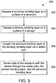
Figure 3 illustrates amethod flowchart 300 of thesystem 100 in accordance with one embodiment. At 302, astructure bonding layer 202 is disposed on asurface 214 of astructure 102. For example, thestructure bonding layer 202 may be a local metallization of thesurface 214 of thestructure 102, or thestructure bonding layer 202 may be a layer of a solderable material that is disposed on thesurface 214 of thestructure 102. Thestructure bonding layer 202 may have a surface area on thesurface 214 of thestructure 102 that is substantially equivalent to a surface area of thesurface 212 of thesensor 104. Optionally, thestructure bonding layer 202 may have a surface area that is greater than or less than the surface area of thesurface 212 of thesensor 104. Optionally, thestructure bonding layer 202 may have a surface area that is substantially the same as the surface area of the metallic joint 106, may have a surface area that is less than the surface area of the metallic joint 106, or may have a surface area that is greater than the surface area of the metallic joint 106. - At 304, a
sensor bonding layer 204 is disposed on asurface 212 of asensor 104. For example, thesensor bonding layer 204 may be a layer of a metallic material. Thestructure bonding layer 202 and thesensor bonding layer 204 may be a common or unique metallic alloys. Thesensor bonding layer 204 may have a surface area that is substantially equivalent to a surface area of thesurface 212 of thesensor 104, may have a surface area that is less than the surface area of thesurface 212, or may have a surface area that is greater than the surface area of thesurface 212. Optionally, thesensor bonding layer 204 may extend an area that is substantially equivalent to, is less then, or is greater than the surface area of the metallic joint 106. - In one or more embodiments, the
sensor bonding layer 204 and/or thestructure bonding layer 202 use self-orientation or self-alignment to assemble thesensor 104 to thestructure 102 via the metallic joint 106. The metallic joint 106 may be a solder layer made of a solder alloy having wetting properties that enables thesensor bonding layer 204 of thesensor 104 to self-align with thestructure bonding layer 202 of thestructure 102 when thesensor 104 is bonded to thestructure 102. For example, the metallic joint 106 allows thesensor 104 to self-align with thestructure 102 without the use of additional pick-and-place equipment, additional fixture equipment, or the like. - At 306, the
structure bonding layer 202 is coupled to thesensor bonding layer 204 via the metallic joint 106. For example, thesensor bonding layer 204 is coupled with afirst side 114 of the metallic joint 106, and thestructure bonding layer 202 is coupled with an opposite,second side 116 of the metallic joint 106. - The
sensor 104 is operably coupled with thestructure 102 via the metallic joint 106 at a location outside of a conventional reflow oven. For example, thestructure 102 may be part of an assembly that may not be able to be transferred to a reflow oven, thestructure 102 may not be able to be disassembled from the assembly to be transferred to a reflow oven, thestructure 102 may not be able to fit inside of a reflow oven, thestructure 102 may be manufacture out of a material that cannot withstand conventional operating temperatures of a conventional reflow oven, or the like. - In one embodiment illustrated in
Figure 4 , thesensor 104 is operably coupled with thestructure 102 via the metallic joint 106 by aninduction coil 402 that applies electrical stimuli to the metallic joint 106. For example, thesensor 104 may be held in a position (e.g., by a fixture, by an operator, or the like) and theinduction coil 402 may be placed in contact with, close by to, around, or the like, thesensor 104 and thesubstrate 102 to which thesensor 104 is to be bonded to. In one embodiment, theinduction coil 402 may be wrapped around thesystem 100, as illustrated inFigure 4 . Additionally or alternatively, theinduction coil 402 may be wrapped around thesensor 104 such that theinduction coil 402 is substantially parallel to thesubstrate 102. Additionally or alternatively, theinduction coil 402 may be placed in contact with thesystem 100 by an alternative configuration. Theinduction coil 402 applies localized electrical stimuli to the metallic joint 106 to activate reflow the metallic joint 106 in order to operably couple thesensor 104 with thestructure 102. - In one embodiment illustrated in
Figure 5 , thesensor 104 is operably coupled with thestructure 102 via the metallic joint 106 by an active reflow process at the metallic joint 106. For example, an exothermic metallic film such as a Reactive Nano Technologies (RNT)film 502, or an alternative material, may be placed within the metallic joint 106 in order to locally reflow the metallic joint 106. Thesensor 104 may be held in a position (e.g., by a fixture, by an operator, or the like). Electrical stimuli that is applied to thefilm 502 by a fixture, an electrical source, or the like, activates reflow of the metallic joint 106 in order to operably couple thesensor 104 with thestructure 102. - Returning to
Figure 3 , at 308, thesensor 104 senses data of thestructure 102 through thestructure bonding layer 202, the metallic joint 106, and thesensor bonding layer 204. For example, thesensor 104 may sense (e.g., collect, read, measure, obtain, or the like) data of thestructure 102. The sensed data of thestructure 102 transfers from thestructure 102, through the metallic joint 106, through the metallic structure bonding layer and sensor bonding layer, to thesensor 104. For example, as the modulus of elasticity of the metallicsensor bonding layer 204 and thestructure bonding layer 202 increases, the transfer of the sensed strain data of thestructure 102 improves relative to a non-metallicsensor bonding layer 204 and non-metallicstructure bonding layer 202. The data of thestructure 102 may include temperature, pressure, stress, strain, or the like. Optionally, the data of thestructure 102 may include sensed data of a fluid that is being contained inside of thestructure 102. Optionally, the data of thestructure 102 may include sensed data of an externality characteristic to which thestructure 102 is exposed (e.g., environmental ambient temperature, ambient pressure, ambient humidity, or the like). Optionally, the sensed data of thestructure 102 may include any alternative data that is sensed (e.g., collected, measured, read, obtained, or the like) by thesensor 104. - In one embodiment of the subject matter described herein, a system includes a structure configured to have a structure bonding layer disposed on a surface of the structure. The structure bonding layer is a metallic alloy. The system includes a sensor configured to have a sensor bonding layer disposed on a surface of the sensor. The sensor bonding layer is a metallic alloy. The sensor bonding layer is configured to be coupled to the structure bonding layer via a metallic joint in order for the sensor to sense data of the structure through the metallic joint, the structure bonding layer, and the sensor bonding layer.
- Optionally, the sensor bonding layer is configured to be coupled to the structure bonding layer via the metallic joint at a location outside of a reflow over.
- Optionally, the data of the structure includes one or more of temperature data, stress data, or strain data.
- Optionally, the structure is one or more of a shaft, a rod, or a blade.
- Optionally, the sensor is configured to self-align with the structure via the metallic joint.
- Optionally, the structure bonding layer is configured to be disposed on an outer surface of the structure.
- Optionally, the system includes an induction coil configured to be in operational contact with the metallic joint. The induction coil is configured to apply electrical stimuli to the metallic joint.
- Optionally, the sensor is a surface acoustic wave (SAW) device.
- Optionally, the SAW device comprises one or more of a strain gauge, a torque sensor, or a temperature sensor.
- In one embodiment of the subject matter described herein, a method includes disposing a structure bonding layer on a surface of a structure. The structure bonding layer is a metallic alloy. The method includes disposing a sensor bonding layer on a surface of a sensor. The sensor bonding layer is a metallic alloy. The structure bonding layer is coupled to the sensor bonding layer via a metallic joint in order for the sensor to sense data of the structure through the metallic joint, the structure bonding layer, and the sensor bonding layer.
- Optionally, coupling the sensor bonding layer to the structure bonding layer via the metallic joint occurs at a location that is outside of a reflow over.
- Optionally, the data of the structure includes one or more of temperature data, stress data, or strain data.
- Optionally, the structure is one or more of a shaft, a rod, or a blade.
- Optionally, the sensor is configured to self-align with the structure via the metallic joint.
- Optionally, the structure bonding layer is configured to be disposed on an outer surface of the structure.
- Optionally, the method includes applying electrical stimuli to the metallic joint with an induction coil configured to be in operation contact with the metallic joint.
- Optionally, the sensor is a surface acoustic wave (SAW) device.
- Optionally, the SAW device comprises one or more of a strain gauge, a torque sensor, or a temperature sensor.
- In one embodiment of the subject matter described herein, a system includes a structure configured to have a structure bonding layer disposed on a surface of the structure. The structure bonding layer is a metallic alloy. The system includes a sensor configured to have a sensor bonding layer disposed on a surface of the sensor. The sensor bonding layer is a metallic alloy. The sensor bonding layer is configured to be coupled to the structure bonding layer via a metallic joint at a location outside of a reflow oven in order for the sensor to sense data of the structure through the metallic joint, the structure bonding layer, and the sensor bonding layer.
- Optionally, the sensor is a surface acoustic wave (SAW) device.
- As used herein, an element or step recited in the singular and proceeded with the word "a" or "an" should be understood as not excluding plural of said elements or steps, unless such exclusion is explicitly stated. Furthermore, references to "one embodiment" of the presently described inventive subject matter are not intended to be interpreted as excluding the existence of additional embodiments that also incorporate the recited features. Moreover, unless explicitly stated to the contrary, embodiments "comprising," "including," or "having" (or like terms) an element, which has a particular property or a plurality of elements with a particular property, may include additional such elements that do not have the particular property.
- As used herein, terms such as "system" or "controller" may include hardware and/or software that operate(s) to perform one or more functions. For example, a system or controller may include a computer processor or other logic-based device that performs operations based on instructions stored on a tangible and non-transitory computer readable storage medium, such as a computer memory. Alternatively, a system or controller may include a hard-wired device that performs operations based on hard-wired logic of the device. The systems and controllers shown in the figures may represent the hardware that operates based on software or hardwired instructions, the software that directs hardware to perform the operations, or a combination thereof.
- As used herein, terms such as "operably connected," "operatively connected," "operably coupled," "operatively coupled" and the like indicate that two or more components are connected in a manner that enables or allows at least one of the components to carry out a designated function. For example, when two or more components are operably connected, one or more connections (electrical and/or wireless connections) may exist that allow the components to communicate with each other, that allow one component to control another component, that allow each component to control the other component, and/or that enable at least one of the components to operate in a designated manner.
- It is to be understood that the subject matter described herein is not limited in its application to the details of construction and the arrangement of elements set forth in the description herein or illustrated in the drawings hereof. The subject matter described herein is capable of other embodiments and of being practiced or of being carried out in various ways. Also, it is to be understood that the phraseology and terminology used herein is for the purpose of description and should not be regarded as limiting. The use of "including," "comprising," or "having" and variations thereof herein is meant to encompass the items listed thereafter and equivalents thereof as well as additional items.
- It is to be understood that the above description is intended to be illustrative, and not restrictive. For example, the above-described embodiments (and/or aspects thereof) may be used in combination with each other. In addition, many modifications may be made to adapt a particular situation or material to the teachings of the presently described subject matter without departing from its scope. While the dimensions, types of materials and coatings described herein are intended to define the parameters of the disclosed subject matter, they are by no means limiting and are exemplary embodiments. Many other embodiments will be apparent to one of ordinary skill in the art upon reviewing the above description. The scope of the inventive subject matter should, therefore, be determined with reference to the appended claims, along with the full scope of equivalents to which such claims are entitled. In the appended claims, the terms "including" and "in which" are used as the plain-English equivalents of the respective terms "comprising" and "wherein." Moreover, in the following claims, the terms "first," "second," and "third," etc. are used merely as labels, and are not intended to impose numerical requirements on their objects. Further, the limitations of the following claims are not written in means-plus-function format and are not intended to be interpreted based on 35 U.S.C. § 112(f), unless and until such claim limitations expressly use the phrase "means for" followed by a statement of function void of further structure.
- This written description uses examples to disclose several embodiments of the inventive subject matter, and also to enable one of ordinary skill in the art to practice the embodiments of inventive subject matter, including making and using any devices or systems and performing any incorporated methods. The patentable scope of the inventive subject matter is defined by the claims, and may include other examples that occur to one of ordinary skill in the art. Such other examples are intended to be within the scope of the claims if they have structural elements that do not differ from the literal language of the claims, or if they include equivalent structural elements with insubstantial differences from the literal languages of the claims.
- 1. A system comprising:
- a structure configured to have a structure bonding layer disposed on a surface of the structure, wherein the structure bonding layer is a metallic alloy; and
- a sensor configured to have a sensor bonding layer disposed on a surface of the sensor, wherein the sensor bonding layer is a metallic alloy;
- wherein the sensor bonding layer is configured to be coupled to the structure bonding layer via a metallic joint in order for the sensor to sense data of the structure through the metallic joint, the structure bonding layer, and the sensor bonding layer.
- 2. The system of clause 1, wherein the sensor bonding layer is configured to be coupled to the structure bonding layer via the metallic joint at a location outside of a reflow oven.
- 3. The system of clause 1, wherein the data of the structure includes one or more of temperature data, stress data, or strain data.
- 4. The system of clause 1, wherein the structure is one or more of a shaft, a rod, or a blade.
- 5. The system of clause 1, wherein the sensor is configured to self-align with the structure via the metallic joint.
- 6. The system of clause 1, wherein the structure bonding layer is configured to be disposed on an outer surface of the structure.
- 7. The system of clause 1, further comprising an induction coil configured to be in operational contact with the metallic joint, the induction coil configured to apply electrical stimuli to the metallic joint.
- 8. The system of clause 1, wherein the sensor is a surface acoustic wave (SAW) device.
- 9. The system of clause 8, wherein the SAW device comprises one or more of a strain gauge, a torque sensor, or a temperature sensor.
- 10. A method comprising:
- disposing a structure bonding layer on a surface of a structure, wherein the structure bonding layer is a metallic alloy;
- disposing a sensor bonding layer on a surface of a sensor, wherein the sensor bonding layer is a metallic alloy; and
- coupling the structure bonding layer to the sensor bonding layer via a metallic joint in order for the sensor to sense data of the structure through the metallic joint, the structure bonding layer, and the sensor bonding layer.
- 11. The method of clause 10, wherein coupling the sensor bonding layer to the structure bonding layer via the metallic joint occurs at a location that is outside of a reflow oven.
- 12. The method of clause 10, wherein the data of the structure includes one or more of temperature data, stress data, or strain data.
- 13. The method of clause 10, wherein the structure is one or more of a shaft, a rod, or a blade.
- 14. The method of clause 10, wherein the sensor is configured to self-align with the structure via the metallic joint.
- 15. The method of clause 10, wherein the structure bonding layer is configured to be disposed on an outer surface of the structure.
- 16. The method of clause 10, further comprising applying electrical stimuli to the metallic joint with an induction coil configured to be in operational contact with the metallic joint.
- 17. The method of clause 10, wherein the sensor is a surface acoustic wave (SAW) device.
- 18. The method of clause 17, wherein the SAW device comprises one or more of a strain gauge, a torque sensor, or a temperature sensor.
- 19. A system comprising:
- a structure configured to have a structure bonding layer disposed on a surface of the structure, wherein the structure bonding layer is a metallic alloy; and
- a sensor configured to have a sensor bonding layer disposed on a surface of the sensor, wherein the sensor bonding layer is a metallic alloy;
- wherein the sensor bonding layer is configured to be coupled to the structure bonding layer via a metallic joint at a location outside of a reflow oven in order for the sensor to sense data of the structure through the metallic joint, the structure bonding layer, and the sensor bonding layer.
- 20. The system of clause 19, wherein the sensor is a surface acoustic wave (SAW) device.
Claims (15)
- A system 100 comprising:a structure 102 configured to have a structure bonding layer 202 disposed on a surface 214 of the structure 102, wherein the structure bonding layer 202 is a metallic alloy; anda sensor 104 configured to have a sensor bonding layer 204 disposed on a surface 212 of the sensor 104, wherein the sensor bonding layer 204 is a metallic alloy;wherein the sensor bonding layer 204 is configured to be coupled to the structure bonding layer 202 via a metallic joint 106 in order for the sensor 104 to sense data of the structure 102 through the metallic joint 106, the structure bonding layer 202, and the sensor bonding layer 204.
- The system 100 of claim 1, wherein the sensor bonding layer 204 is configured to be coupled to the structure bonding layer 202 via the metallic joint 106 at a location outside of a reflow oven.
- The system 100 of claim 1 or 2, wherein the data of the structure 102 includes one or more of temperature data, stress data, or strain data.
- The system 100 of any one of claims 1 to 3, wherein the structure 102 is one or more of a shaft, a rod, or a blade.
- The system 100 of any one of claims 1 to 4, wherein the sensor 104 is configured to self-align with the structure 102 via the metallic joint 106.
- The system 100 of any one of claims 1 to 5, wherein the structure bonding layer 202 is configured to be disposed on an outer surface of the structure 102.
- The system 100 of any one of claims 1 to 6, further comprising an induction coil 402 configured to be in operational contact with the metallic joint 106, the induction coil 402 configured to apply electrical stimuli to the metallic joint 106.
- The system 100 of any one of claims 1 to 7, wherein the sensor 104 is a surface acoustic wave (SAW) device.
- The system 100 of claim 8, wherein the SAW device comprises one or more of a strain gauge, a torque sensor, or a temperature sensor.
- A method 300 comprising:disposing a structure bonding layer 202 on a surface 214 of a structure 102, wherein the structure bonding layer 202 is a metallic alloy;disposing a sensor bonding layer 204 on a surface of a sensor 104, wherein the sensor bonding layer 204 is a metallic alloy; andcoupling the structure bonding layer 202 to the sensor bonding layer 204 via a metallic joint 106 in order for the sensor 104 to sense data of the structure 102 through the metallic joint 106, the structure bonding layer 202, and the sensor bonding layer 204.
- The method 300 of claim 10, wherein coupling the sensor bonding layer 204 to the structure bonding layer 202 via the metallic joint 106 occurs at a location that is outside of a reflow oven.
- The method 300 of claim 10 or 11, wherein the sensor 104 is configured to self-align with the structure 102 via the metallic joint 106.
- The method 300 of any one of claims 10 to 12, further comprising applying electrical stimuli to the metallic joint 106 with an induction coil 402 configured to be in operational contact with the metallic joint 106.
- The method 300 of any one of claims 10 to 13, wherein the sensor 104 is a surface acoustic wave (SAW) device.
- A system 100 comprising:a structure 102 configured to have a structure bonding layer 202 disposed on a surface 214 of the structure 102, wherein the structure bonding layer 202 is a metallic alloy; anda sensor 104 configured to have a sensor bonding layer 204 disposed on a surface 212 of the sensor 104, wherein the sensor bonding layer 204 is a metallic alloy;wherein the sensor bonding layer 204 is configured to be coupled to the structure bonding layer 202 via a metallic joint 106 at a location outside of a reflow oven in order for the sensor 104 to sense data of the structure 102 through the metallic joint 106, the structure bonding layer 202, and the sensor bonding layer 204.
Applications Claiming Priority (1)
| Application Number | Priority Date | Filing Date | Title |
|---|---|---|---|
| US15/616,105 US10605785B2 (en) | 2017-06-07 | 2017-06-07 | Sensor system and method |
Publications (2)
| Publication Number | Publication Date |
|---|---|
| EP3415888A1 true EP3415888A1 (en) | 2018-12-19 |
| EP3415888B1 EP3415888B1 (en) | 2021-12-01 |
Family
ID=62528313
Family Applications (1)
| Application Number | Title | Priority Date | Filing Date |
|---|---|---|---|
| EP18175715.4A Active EP3415888B1 (en) | 2017-06-07 | 2018-06-04 | Sensor system and method |
Country Status (4)
| Country | Link |
|---|---|
| US (1) | US10605785B2 (en) |
| EP (1) | EP3415888B1 (en) |
| CN (1) | CN109000695B (en) |
| CA (1) | CA3006096C (en) |
Cited By (2)
| Publication number | Priority date | Publication date | Assignee | Title |
|---|---|---|---|---|
| EP3839460A1 (en) * | 2019-12-19 | 2021-06-23 | General Electric Company | Sensor system and method |
| US11079359B2 (en) | 2017-06-07 | 2021-08-03 | General Electric Company | Sensor system and method |
Families Citing this family (5)
| Publication number | Priority date | Publication date | Assignee | Title |
|---|---|---|---|---|
| CN110231103B (en) * | 2019-06-27 | 2020-07-28 | 河海大学常州校区 | A composite coding type SAW temperature and pressure integrated sensor and preparation method thereof |
| US10914617B1 (en) * | 2019-07-29 | 2021-02-09 | Terumo Cardiovascular Systems Corporation | Flexible sensor mount for hard shell blood reservoir |
| DE102022106080A1 (en) | 2022-03-16 | 2023-09-21 | Schaeffler Technologies AG & Co. KG | Method for assembling a sensor element and sensor arrangement with the sensor element |
| US12298197B2 (en) | 2023-01-09 | 2025-05-13 | General Electric Company | System and method for reducing motoring time in a turbomachine based on shaft deflection |
| US20250362125A1 (en) * | 2024-05-24 | 2025-11-27 | General Electric Company | Appartus and method for measuring mechanical strain |
Citations (3)
| Publication number | Priority date | Publication date | Assignee | Title |
|---|---|---|---|---|
| DE19856951A1 (en) * | 1998-12-10 | 1999-10-21 | Bosch Gmbh Robert | Sensor system for determining mechanical variables at structural element eg. pressure with evaluation of propagation condition of acoustic surface waves SAW using measuring element of piezoelectric |
| US20070105341A1 (en) * | 2005-11-09 | 2007-05-10 | The Regents Of The University Of California | Bonding metals and non-metals using inductive heating |
| US9543736B1 (en) * | 2015-11-20 | 2017-01-10 | International Business Machines Corporation | Optimized solder pads for solder induced alignment of opto-electronic chips |
Family Cites Families (27)
| Publication number | Priority date | Publication date | Assignee | Title |
|---|---|---|---|---|
| US5102029A (en) * | 1990-06-22 | 1992-04-07 | Watkins-Johnson Company | Microwave integrated circuit package to eliminate alumina substrate cracking and method |
| JPH04164837A (en) * | 1990-10-30 | 1992-06-10 | Nippon Cement Co Ltd | Stress-buffering structure for ceramic-metal bonded material |
| US5459368A (en) | 1993-08-06 | 1995-10-17 | Matsushita Electric Industrial Co., Ltd. | Surface acoustic wave device mounted module |
| US6853067B1 (en) | 1999-10-12 | 2005-02-08 | Microassembly Technologies, Inc. | Microelectromechanical systems using thermocompression bonding |
| AU1529901A (en) * | 1999-11-22 | 2001-06-04 | Smithkline Beecham Plc | Compounds |
| WO2001067058A1 (en) | 2000-03-10 | 2001-09-13 | Siemens Aktiengesellschaft | Method and device for measuring the moment acting upon a component |
| JP4166997B2 (en) | 2002-03-29 | 2008-10-15 | 富士通メディアデバイス株式会社 | Surface acoustic wave device mounting method and surface acoustic wave device having resin-sealed surface acoustic wave device |
| CN100546180C (en) | 2005-08-24 | 2009-09-30 | 京瓷株式会社 | Surface acoustic wave device and manufacturing method thereof |
| DE102005053531A1 (en) * | 2005-11-08 | 2007-05-10 | Man Turbo Ag | Heat-insulating protective layer for a component within the hot gas region of a gas turbine |
| US20070188054A1 (en) | 2006-02-13 | 2007-08-16 | Honeywell International Inc. | Surface acoustic wave packages and methods of forming same |
| WO2008133293A1 (en) * | 2007-04-25 | 2008-11-06 | Hitachi Chemical Company, Ltd. | Adhesive sheet |
| US7605466B2 (en) | 2007-10-15 | 2009-10-20 | General Electric Company | Sealed wafer packaging of microelectromechanical systems |
| US20100132404A1 (en) * | 2008-12-03 | 2010-06-03 | Progressive Cooling Solutions, Inc. | Bonds and method for forming bonds for a two-phase cooling apparatus |
| EP2230329A1 (en) * | 2009-03-18 | 2010-09-22 | Siemens Aktiengesellschaft | Dual layer porous coating system with pyrochlorine phase |
| CN111326435B (en) * | 2010-04-23 | 2023-12-01 | 株式会社半导体能源研究所 | Semiconductor device manufacturing method |
| KR20130097206A (en) * | 2010-09-20 | 2013-09-02 | 신세스 게엠바하 | Compliant implant |
| CN102175358A (en) | 2010-12-06 | 2011-09-07 | 北京理工大学 | Passive wireless surface acoustic wave stress sensor adopting three-layer stress transferring model |
| US9166364B2 (en) * | 2011-02-14 | 2015-10-20 | Spectrasensors, Inc. | Semiconductor laser mounting with intact diffusion barrier layer |
| DE102013004383B4 (en) * | 2013-03-12 | 2015-06-03 | Diehl Metall Stiftung & Co. Kg | Use of a copper-zinc alloy |
| US9791470B2 (en) | 2013-12-27 | 2017-10-17 | Intel Corporation | Magnet placement for integrated sensor packages |
| EP3111202B1 (en) * | 2014-02-27 | 2021-07-14 | 3M Innovative Properties Company | Flexible sensor patch and method of using the same |
| US20150264808A1 (en) * | 2014-03-14 | 2015-09-17 | Eric Colin Bretschneider | Solder Attachment of Electrical Components |
| US9702772B2 (en) * | 2014-03-26 | 2017-07-11 | Mnemonics, Inc. | Surface acoustic wave (SAW) based strain sensor |
| CN103924204B (en) | 2014-04-25 | 2015-12-30 | 电子科技大学 | A kind of method preparing C axle orientation aluminium nitride film at titanium alloy substrate surface |
| US10388607B2 (en) * | 2014-12-17 | 2019-08-20 | Nxp Usa, Inc. | Microelectronic devices with multi-layer package surface conductors and methods of their fabrication |
| US9589869B2 (en) * | 2015-03-11 | 2017-03-07 | Gan Systems Inc. | Packaging solutions for devices and systems comprising lateral GaN power transistors |
| US10432168B2 (en) | 2015-08-31 | 2019-10-01 | General Electric Company | Systems and methods for quartz wafer bonding |
-
2017
- 2017-06-07 US US15/616,105 patent/US10605785B2/en active Active
-
2018
- 2018-05-24 CA CA3006096A patent/CA3006096C/en active Active
- 2018-06-04 EP EP18175715.4A patent/EP3415888B1/en active Active
- 2018-06-07 CN CN201810579900.4A patent/CN109000695B/en active Active
Patent Citations (3)
| Publication number | Priority date | Publication date | Assignee | Title |
|---|---|---|---|---|
| DE19856951A1 (en) * | 1998-12-10 | 1999-10-21 | Bosch Gmbh Robert | Sensor system for determining mechanical variables at structural element eg. pressure with evaluation of propagation condition of acoustic surface waves SAW using measuring element of piezoelectric |
| US20070105341A1 (en) * | 2005-11-09 | 2007-05-10 | The Regents Of The University Of California | Bonding metals and non-metals using inductive heating |
| US9543736B1 (en) * | 2015-11-20 | 2017-01-10 | International Business Machines Corporation | Optimized solder pads for solder induced alignment of opto-electronic chips |
Cited By (5)
| Publication number | Priority date | Publication date | Assignee | Title |
|---|---|---|---|---|
| US11079359B2 (en) | 2017-06-07 | 2021-08-03 | General Electric Company | Sensor system and method |
| US11630086B2 (en) | 2017-06-07 | 2023-04-18 | General Electric Company | Sensor system and method |
| US11982645B2 (en) | 2017-06-07 | 2024-05-14 | General Electric Company | Sensor system and method |
| EP3839460A1 (en) * | 2019-12-19 | 2021-06-23 | General Electric Company | Sensor system and method |
| EP4628864A3 (en) * | 2019-12-19 | 2025-12-31 | General Electric Company | SENSOR SYSTEM AND METHOD |
Also Published As
| Publication number | Publication date |
|---|---|
| US10605785B2 (en) | 2020-03-31 |
| CN109000695B (en) | 2022-03-29 |
| CA3006096A1 (en) | 2018-12-07 |
| US20180356368A1 (en) | 2018-12-13 |
| EP3415888B1 (en) | 2021-12-01 |
| CA3006096C (en) | 2024-04-02 |
| CN109000695A (en) | 2018-12-14 |
Similar Documents
| Publication | Publication Date | Title |
|---|---|---|
| US10605785B2 (en) | Sensor system and method | |
| US11982645B2 (en) | Sensor system and method | |
| EP4628864A2 (en) | Sensor system and method | |
| Hossain et al. | Fabrication of smart parts using powder bed fusion additive manufacturing technology | |
| McCluskey et al. | Reliability of high temperature solder alternatives | |
| EP2865195B1 (en) | A wireless telemetry system including an induction power system | |
| JP5998379B2 (en) | Sensor device package and method | |
| EP3097427B1 (en) | Component with internal sensor and method of additive manufacture | |
| Quintero et al. | Temperature cycling reliability of high-temperature lead-free die-attach technologies | |
| CN105424260B (en) | Pressure sensor device and method for manufacturing pressure sensor device | |
| CN104359393A (en) | Strain gauge and methods for manufacturing and mounting strain gauge | |
| KR20080087290A (en) | Shear Stress-Strain Evaluation Method of Solder Joint by Microdynamic Test Method | |
| KR20110053959A (en) | Wireless telemetry circuit package for high temperature environments | |
| US20170191879A1 (en) | Temperature sensors with integrated sensing components | |
| EP3504527B1 (en) | Process pressure transmitter with polymer seal | |
| CN112166310B (en) | Device for measuring strain and method for making and using the device | |
| Feißt et al. | Material model and simulation of multilayer-AgSn-foils for transient-liquid-phase bonding of sensor elements | |
| EP3358327B1 (en) | Semiconductor sensor device and method for manufacturing same | |
| KR20040075398A (en) | Miniaturized shear-punch tester and evaluating method of shear strength and shear strain for solder joint | |
| CN113984253A (en) | Preparation method of resistance strain gate sensor | |
| Samet et al. | Examination of Consistent Application of Interfacial Fracture Energy Versus Mode-Mixity Curve for Delamination Prediction | |
| WO2021126261A1 (en) | Strain gages and methods for manufacturing thereof | |
| EP4249876A1 (en) | Sensing element and related methods | |
| Feisst et al. | Low-Temperature Metallic Joints for Strain-Sensing Sensor Dies | |
| Au et al. | Extremely high temperature and high pressure (x-HTHP) endurable SOI device and sensor packaging for harsh environment applications |
Legal Events
| Date | Code | Title | Description |
|---|---|---|---|
| PUAI | Public reference made under article 153(3) epc to a published international application that has entered the european phase |
Free format text: ORIGINAL CODE: 0009012 |
|
| STAA | Information on the status of an ep patent application or granted ep patent |
Free format text: STATUS: THE APPLICATION HAS BEEN PUBLISHED |
|
| AK | Designated contracting states |
Kind code of ref document: A1 Designated state(s): AL AT BE BG CH CY CZ DE DK EE ES FI FR GB GR HR HU IE IS IT LI LT LU LV MC MK MT NL NO PL PT RO RS SE SI SK SM TR |
|
| AX | Request for extension of the european patent |
Extension state: BA ME |
|
| STAA | Information on the status of an ep patent application or granted ep patent |
Free format text: STATUS: REQUEST FOR EXAMINATION WAS MADE |
|
| 17P | Request for examination filed |
Effective date: 20190619 |
|
| RBV | Designated contracting states (corrected) |
Designated state(s): AL AT BE BG CH CY CZ DE DK EE ES FI FR GB GR HR HU IE IS IT LI LT LU LV MC MK MT NL NO PL PT RO RS SE SI SK SM TR |
|
| STAA | Information on the status of an ep patent application or granted ep patent |
Free format text: STATUS: EXAMINATION IS IN PROGRESS |
|
| 17Q | First examination report despatched |
Effective date: 20200908 |
|
| GRAP | Despatch of communication of intention to grant a patent |
Free format text: ORIGINAL CODE: EPIDOSNIGR1 |
|
| STAA | Information on the status of an ep patent application or granted ep patent |
Free format text: STATUS: GRANT OF PATENT IS INTENDED |
|
| INTG | Intention to grant announced |
Effective date: 20210622 |
|
| GRAS | Grant fee paid |
Free format text: ORIGINAL CODE: EPIDOSNIGR3 |
|
| GRAA | (expected) grant |
Free format text: ORIGINAL CODE: 0009210 |
|
| STAA | Information on the status of an ep patent application or granted ep patent |
Free format text: STATUS: THE PATENT HAS BEEN GRANTED |
|
| AK | Designated contracting states |
Kind code of ref document: B1 Designated state(s): AL AT BE BG CH CY CZ DE DK EE ES FI FR GB GR HR HU IE IS IT LI LT LU LV MC MK MT NL NO PL PT RO RS SE SI SK SM TR |
|
| REG | Reference to a national code |
Ref country code: GB Ref legal event code: FG4D |
|
| REG | Reference to a national code |
Ref country code: AT Ref legal event code: REF Ref document number: 1452209 Country of ref document: AT Kind code of ref document: T Effective date: 20211215 Ref country code: CH Ref legal event code: EP |
|
| REG | Reference to a national code |
Ref country code: IE Ref legal event code: FG4D |
|
| REG | Reference to a national code |
Ref country code: DE Ref legal event code: R096 Ref document number: 602018027357 Country of ref document: DE |
|
| REG | Reference to a national code |
Ref country code: LT Ref legal event code: MG9D |
|
| REG | Reference to a national code |
Ref country code: NL Ref legal event code: MP Effective date: 20211201 |
|
| REG | Reference to a national code |
Ref country code: AT Ref legal event code: MK05 Ref document number: 1452209 Country of ref document: AT Kind code of ref document: T Effective date: 20211201 |
|
| PG25 | Lapsed in a contracting state [announced via postgrant information from national office to epo] |
Ref country code: RS Free format text: LAPSE BECAUSE OF FAILURE TO SUBMIT A TRANSLATION OF THE DESCRIPTION OR TO PAY THE FEE WITHIN THE PRESCRIBED TIME-LIMIT Effective date: 20211201 Ref country code: LT Free format text: LAPSE BECAUSE OF FAILURE TO SUBMIT A TRANSLATION OF THE DESCRIPTION OR TO PAY THE FEE WITHIN THE PRESCRIBED TIME-LIMIT Effective date: 20211201 Ref country code: FI Free format text: LAPSE BECAUSE OF FAILURE TO SUBMIT A TRANSLATION OF THE DESCRIPTION OR TO PAY THE FEE WITHIN THE PRESCRIBED TIME-LIMIT Effective date: 20211201 Ref country code: BG Free format text: LAPSE BECAUSE OF FAILURE TO SUBMIT A TRANSLATION OF THE DESCRIPTION OR TO PAY THE FEE WITHIN THE PRESCRIBED TIME-LIMIT Effective date: 20220301 Ref country code: AT Free format text: LAPSE BECAUSE OF FAILURE TO SUBMIT A TRANSLATION OF THE DESCRIPTION OR TO PAY THE FEE WITHIN THE PRESCRIBED TIME-LIMIT Effective date: 20211201 |
|
| PG25 | Lapsed in a contracting state [announced via postgrant information from national office to epo] |
Ref country code: SE Free format text: LAPSE BECAUSE OF FAILURE TO SUBMIT A TRANSLATION OF THE DESCRIPTION OR TO PAY THE FEE WITHIN THE PRESCRIBED TIME-LIMIT Effective date: 20211201 Ref country code: PL Free format text: LAPSE BECAUSE OF FAILURE TO SUBMIT A TRANSLATION OF THE DESCRIPTION OR TO PAY THE FEE WITHIN THE PRESCRIBED TIME-LIMIT Effective date: 20211201 Ref country code: NO Free format text: LAPSE BECAUSE OF FAILURE TO SUBMIT A TRANSLATION OF THE DESCRIPTION OR TO PAY THE FEE WITHIN THE PRESCRIBED TIME-LIMIT Effective date: 20220301 Ref country code: LV Free format text: LAPSE BECAUSE OF FAILURE TO SUBMIT A TRANSLATION OF THE DESCRIPTION OR TO PAY THE FEE WITHIN THE PRESCRIBED TIME-LIMIT Effective date: 20211201 Ref country code: HR Free format text: LAPSE BECAUSE OF FAILURE TO SUBMIT A TRANSLATION OF THE DESCRIPTION OR TO PAY THE FEE WITHIN THE PRESCRIBED TIME-LIMIT Effective date: 20211201 Ref country code: GR Free format text: LAPSE BECAUSE OF FAILURE TO SUBMIT A TRANSLATION OF THE DESCRIPTION OR TO PAY THE FEE WITHIN THE PRESCRIBED TIME-LIMIT Effective date: 20220302 Ref country code: ES Free format text: LAPSE BECAUSE OF FAILURE TO SUBMIT A TRANSLATION OF THE DESCRIPTION OR TO PAY THE FEE WITHIN THE PRESCRIBED TIME-LIMIT Effective date: 20211201 |
|
| PG25 | Lapsed in a contracting state [announced via postgrant information from national office to epo] |
Ref country code: NL Free format text: LAPSE BECAUSE OF FAILURE TO SUBMIT A TRANSLATION OF THE DESCRIPTION OR TO PAY THE FEE WITHIN THE PRESCRIBED TIME-LIMIT Effective date: 20211201 |
|
| PG25 | Lapsed in a contracting state [announced via postgrant information from national office to epo] |
Ref country code: SM Free format text: LAPSE BECAUSE OF FAILURE TO SUBMIT A TRANSLATION OF THE DESCRIPTION OR TO PAY THE FEE WITHIN THE PRESCRIBED TIME-LIMIT Effective date: 20211201 Ref country code: SK Free format text: LAPSE BECAUSE OF FAILURE TO SUBMIT A TRANSLATION OF THE DESCRIPTION OR TO PAY THE FEE WITHIN THE PRESCRIBED TIME-LIMIT Effective date: 20211201 Ref country code: RO Free format text: LAPSE BECAUSE OF FAILURE TO SUBMIT A TRANSLATION OF THE DESCRIPTION OR TO PAY THE FEE WITHIN THE PRESCRIBED TIME-LIMIT Effective date: 20211201 Ref country code: PT Free format text: LAPSE BECAUSE OF FAILURE TO SUBMIT A TRANSLATION OF THE DESCRIPTION OR TO PAY THE FEE WITHIN THE PRESCRIBED TIME-LIMIT Effective date: 20220401 Ref country code: EE Free format text: LAPSE BECAUSE OF FAILURE TO SUBMIT A TRANSLATION OF THE DESCRIPTION OR TO PAY THE FEE WITHIN THE PRESCRIBED TIME-LIMIT Effective date: 20211201 Ref country code: CZ Free format text: LAPSE BECAUSE OF FAILURE TO SUBMIT A TRANSLATION OF THE DESCRIPTION OR TO PAY THE FEE WITHIN THE PRESCRIBED TIME-LIMIT Effective date: 20211201 |
|
| REG | Reference to a national code |
Ref country code: DE Ref legal event code: R097 Ref document number: 602018027357 Country of ref document: DE |
|
| PG25 | Lapsed in a contracting state [announced via postgrant information from national office to epo] |
Ref country code: IS Free format text: LAPSE BECAUSE OF FAILURE TO SUBMIT A TRANSLATION OF THE DESCRIPTION OR TO PAY THE FEE WITHIN THE PRESCRIBED TIME-LIMIT Effective date: 20220401 |
|
| PLBE | No opposition filed within time limit |
Free format text: ORIGINAL CODE: 0009261 |
|
| STAA | Information on the status of an ep patent application or granted ep patent |
Free format text: STATUS: NO OPPOSITION FILED WITHIN TIME LIMIT |
|
| PG25 | Lapsed in a contracting state [announced via postgrant information from national office to epo] |
Ref country code: DK Free format text: LAPSE BECAUSE OF FAILURE TO SUBMIT A TRANSLATION OF THE DESCRIPTION OR TO PAY THE FEE WITHIN THE PRESCRIBED TIME-LIMIT Effective date: 20211201 Ref country code: AL Free format text: LAPSE BECAUSE OF FAILURE TO SUBMIT A TRANSLATION OF THE DESCRIPTION OR TO PAY THE FEE WITHIN THE PRESCRIBED TIME-LIMIT Effective date: 20211201 |
|
| 26N | No opposition filed |
Effective date: 20220902 |
|
| PG25 | Lapsed in a contracting state [announced via postgrant information from national office to epo] |
Ref country code: SI Free format text: LAPSE BECAUSE OF FAILURE TO SUBMIT A TRANSLATION OF THE DESCRIPTION OR TO PAY THE FEE WITHIN THE PRESCRIBED TIME-LIMIT Effective date: 20211201 |
|
| PG25 | Lapsed in a contracting state [announced via postgrant information from national office to epo] |
Ref country code: MC Free format text: LAPSE BECAUSE OF FAILURE TO SUBMIT A TRANSLATION OF THE DESCRIPTION OR TO PAY THE FEE WITHIN THE PRESCRIBED TIME-LIMIT Effective date: 20211201 |
|
| REG | Reference to a national code |
Ref country code: CH Ref legal event code: PL |
|
| REG | Reference to a national code |
Ref country code: BE Ref legal event code: MM Effective date: 20220630 |
|
| PG25 | Lapsed in a contracting state [announced via postgrant information from national office to epo] |
Ref country code: LU Free format text: LAPSE BECAUSE OF NON-PAYMENT OF DUE FEES Effective date: 20220604 Ref country code: LI Free format text: LAPSE BECAUSE OF NON-PAYMENT OF DUE FEES Effective date: 20220630 Ref country code: IE Free format text: LAPSE BECAUSE OF NON-PAYMENT OF DUE FEES Effective date: 20220604 Ref country code: CH Free format text: LAPSE BECAUSE OF NON-PAYMENT OF DUE FEES Effective date: 20220630 |
|
| PG25 | Lapsed in a contracting state [announced via postgrant information from national office to epo] |
Ref country code: IT Free format text: LAPSE BECAUSE OF FAILURE TO SUBMIT A TRANSLATION OF THE DESCRIPTION OR TO PAY THE FEE WITHIN THE PRESCRIBED TIME-LIMIT Effective date: 20211201 Ref country code: BE Free format text: LAPSE BECAUSE OF NON-PAYMENT OF DUE FEES Effective date: 20220630 |
|
| P01 | Opt-out of the competence of the unified patent court (upc) registered |
Effective date: 20230414 |
|
| PG25 | Lapsed in a contracting state [announced via postgrant information from national office to epo] |
Ref country code: HU Free format text: LAPSE BECAUSE OF FAILURE TO SUBMIT A TRANSLATION OF THE DESCRIPTION OR TO PAY THE FEE WITHIN THE PRESCRIBED TIME-LIMIT; INVALID AB INITIO Effective date: 20180604 |
|
| PG25 | Lapsed in a contracting state [announced via postgrant information from national office to epo] |
Ref country code: MK Free format text: LAPSE BECAUSE OF FAILURE TO SUBMIT A TRANSLATION OF THE DESCRIPTION OR TO PAY THE FEE WITHIN THE PRESCRIBED TIME-LIMIT Effective date: 20211201 Ref country code: CY Free format text: LAPSE BECAUSE OF FAILURE TO SUBMIT A TRANSLATION OF THE DESCRIPTION OR TO PAY THE FEE WITHIN THE PRESCRIBED TIME-LIMIT Effective date: 20211201 |
|
| PG25 | Lapsed in a contracting state [announced via postgrant information from national office to epo] |
Ref country code: MT Free format text: LAPSE BECAUSE OF FAILURE TO SUBMIT A TRANSLATION OF THE DESCRIPTION OR TO PAY THE FEE WITHIN THE PRESCRIBED TIME-LIMIT Effective date: 20211201 |
|
| PGFP | Annual fee paid to national office [announced via postgrant information from national office to epo] |
Ref country code: DE Payment date: 20250520 Year of fee payment: 8 |
|
| PGFP | Annual fee paid to national office [announced via postgrant information from national office to epo] |
Ref country code: GB Payment date: 20250520 Year of fee payment: 8 |
|
| PGFP | Annual fee paid to national office [announced via postgrant information from national office to epo] |
Ref country code: FR Payment date: 20250520 Year of fee payment: 8 |
|
| PG25 | Lapsed in a contracting state [announced via postgrant information from national office to epo] |
Ref country code: TR Free format text: LAPSE BECAUSE OF FAILURE TO SUBMIT A TRANSLATION OF THE DESCRIPTION OR TO PAY THE FEE WITHIN THE PRESCRIBED TIME-LIMIT Effective date: 20211201 |