EP3415814A1 - Light guide device, lighting apparatus and motor vehicle - Google Patents
Light guide device, lighting apparatus and motor vehicle Download PDFInfo
- Publication number
- EP3415814A1 EP3415814A1 EP18177469.6A EP18177469A EP3415814A1 EP 3415814 A1 EP3415814 A1 EP 3415814A1 EP 18177469 A EP18177469 A EP 18177469A EP 3415814 A1 EP3415814 A1 EP 3415814A1
- Authority
- EP
- European Patent Office
- Prior art keywords
- guide device
- light guide
- light
- edge
- light incident
- Prior art date
- Legal status (The legal status is an assumption and is not a legal conclusion. Google has not performed a legal analysis and makes no representation as to the accuracy of the status listed.)
- Granted
Links
Images


Classifications
-
- G—PHYSICS
- G02—OPTICS
- G02B—OPTICAL ELEMENTS, SYSTEMS OR APPARATUS
- G02B6/00—Light guides; Structural details of arrangements comprising light guides and other optical elements, e.g. couplings
- G02B6/0001—Light guides; Structural details of arrangements comprising light guides and other optical elements, e.g. couplings specially adapted for lighting devices or systems
- G02B6/0005—Light guides; Structural details of arrangements comprising light guides and other optical elements, e.g. couplings specially adapted for lighting devices or systems the light guides being of the fibre type
- G02B6/0006—Coupling light into the fibre
-
- G—PHYSICS
- G02—OPTICS
- G02B—OPTICAL ELEMENTS, SYSTEMS OR APPARATUS
- G02B6/00—Light guides; Structural details of arrangements comprising light guides and other optical elements, e.g. couplings
- G02B6/0001—Light guides; Structural details of arrangements comprising light guides and other optical elements, e.g. couplings specially adapted for lighting devices or systems
- G02B6/0011—Light guides; Structural details of arrangements comprising light guides and other optical elements, e.g. couplings specially adapted for lighting devices or systems the light guides being planar or of plate-like form
- G02B6/0013—Means for improving the coupling-in of light from the light source into the light guide
- G02B6/0015—Means for improving the coupling-in of light from the light source into the light guide provided on the surface of the light guide or in the bulk of it
- G02B6/0018—Redirecting means on the surface of the light guide
-
- G—PHYSICS
- G02—OPTICS
- G02B—OPTICAL ELEMENTS, SYSTEMS OR APPARATUS
- G02B6/00—Light guides; Structural details of arrangements comprising light guides and other optical elements, e.g. couplings
- G02B6/0001—Light guides; Structural details of arrangements comprising light guides and other optical elements, e.g. couplings specially adapted for lighting devices or systems
- G02B6/0011—Light guides; Structural details of arrangements comprising light guides and other optical elements, e.g. couplings specially adapted for lighting devices or systems the light guides being planar or of plate-like form
- G02B6/0013—Means for improving the coupling-in of light from the light source into the light guide
-
- G—PHYSICS
- G02—OPTICS
- G02B—OPTICAL ELEMENTS, SYSTEMS OR APPARATUS
- G02B6/00—Light guides; Structural details of arrangements comprising light guides and other optical elements, e.g. couplings
- G02B6/0001—Light guides; Structural details of arrangements comprising light guides and other optical elements, e.g. couplings specially adapted for lighting devices or systems
- G02B6/0011—Light guides; Structural details of arrangements comprising light guides and other optical elements, e.g. couplings specially adapted for lighting devices or systems the light guides being planar or of plate-like form
- G02B6/0013—Means for improving the coupling-in of light from the light source into the light guide
- G02B6/0015—Means for improving the coupling-in of light from the light source into the light guide provided on the surface of the light guide or in the bulk of it
- G02B6/002—Means for improving the coupling-in of light from the light source into the light guide provided on the surface of the light guide or in the bulk of it by shaping at least a portion of the light guide, e.g. with collimating, focussing or diverging surfaces
-
- F—MECHANICAL ENGINEERING; LIGHTING; HEATING; WEAPONS; BLASTING
- F21—LIGHTING
- F21S—NON-PORTABLE LIGHTING DEVICES; SYSTEMS THEREOF; VEHICLE LIGHTING DEVICES SPECIALLY ADAPTED FOR VEHICLE EXTERIORS
- F21S43/00—Signalling devices specially adapted for vehicle exteriors, e.g. brake lamps, direction indicator lights or reversing lights
- F21S43/20—Signalling devices specially adapted for vehicle exteriors, e.g. brake lamps, direction indicator lights or reversing lights characterised by refractors, transparent cover plates, light guides or filters
- F21S43/235—Light guides
- F21S43/236—Light guides characterised by the shape of the light guide
- F21S43/237—Light guides characterised by the shape of the light guide rod-shaped
-
- G—PHYSICS
- G02—OPTICS
- G02B—OPTICAL ELEMENTS, SYSTEMS OR APPARATUS
- G02B6/00—Light guides; Structural details of arrangements comprising light guides and other optical elements, e.g. couplings
- G02B6/0001—Light guides; Structural details of arrangements comprising light guides and other optical elements, e.g. couplings specially adapted for lighting devices or systems
- G02B6/0011—Light guides; Structural details of arrangements comprising light guides and other optical elements, e.g. couplings specially adapted for lighting devices or systems the light guides being planar or of plate-like form
- G02B6/0013—Means for improving the coupling-in of light from the light source into the light guide
- G02B6/0015—Means for improving the coupling-in of light from the light source into the light guide provided on the surface of the light guide or in the bulk of it
- G02B6/002—Means for improving the coupling-in of light from the light source into the light guide provided on the surface of the light guide or in the bulk of it by shaping at least a portion of the light guide, e.g. with collimating, focussing or diverging surfaces
- G02B6/0021—Means for improving the coupling-in of light from the light source into the light guide provided on the surface of the light guide or in the bulk of it by shaping at least a portion of the light guide, e.g. with collimating, focussing or diverging surfaces for housing at least a part of the light source, e.g. by forming holes or recesses
Definitions
- the present invention relates to a light guide device, a lighting apparatus and a motor vehicle.
- a light guide device refers to a device for guiding light in which the light travels primarily by total reflection.
- the light guide device is widely used in the fields of lighting, light transmission, and the like. It may have various shapes, of such as a cylinder (referred to as a light guide rod), an elongated shape (referred to as a light guide bar, a light bar), a plate shape (referred to as a light guide plate), a ring (referred to as a light guide ring), and the like.
- the light guide device may generally receive an incident light at its end thereof and conduct light to another end of the light guide device or any desired exit position by the total reflection of its outer wall. Generally, the incident end face of the light guide device is a planar structure of such as a circle, or a square.
- the light guide device may be used, for example, in a lighting device for conducting light emitted by the light source to a desired position.
- the present invention also provides an illumination apparatus including the light guide device and a motor vehicle including the lighting apparatus.
- An embodiment of the present invention provides a light guide device comprising: a light incident end configured to receive an incident light, wherein the light incident end has at least one light incident face and each light incident face has a first edge and a second edge that are displaced from each other in a direction along an axis of the light guide device.
- the light incident end has one light incident face which is a curved face extending between the first edge and the second edge.
- the light incident end has a plurality of the light incident faces arranged in a direction about the axis of the light guide device.
- the first edge is located at upstream of the second edge in each of the light incident faces in a clockwise or anti-clockwise direction about the axis of the light guide device, and the first edge is displaced towards inside of the light guide device in the direction along the axis of the light guide device, with respect to the second edge in each of the light incident faces.
- the first edge is located at upstream of the second edge in each of the light incident faces in a clockwise or anti-clockwise direction about the axis of the light guide device, and the first edge is displaced towards outside of the light guide device in the direction along the axis of the light guide device, with respect to the second edge in each of the light incident faces.
- the first edge is located at upstream of the second edge in each of the light incident faces in a clockwise or anti-clockwise direction about the axis of the light guide device, and the light incident faces are divided into a first group of the light incident faces and a second group of the light incident faces, and wherein the first edge is displaced towards inside of the light guide device in the direction along the axis of the light guide device, with respect to the second edge in each of the first group of the light incident faces, and wherein the first edge is displaced towards outside of the light guide device in the direction along the axis of the light guide device, with respect to the second edge in each of the second group of the light incident faces.
- the first group of the light incident faces and the second group of the light incident faces are arranged alternately in the direction about the axis of the light guide device.
- the light incident faces are planar faces or curved faces.
- the first edge and the second edge extend from a periphery of the light incident end towards a center of the light incident end.
- the light incident end further comprises a central light transmission planar face which is located at a central position of the light incident end and is perpendicular to the axis of the light guide device, the at least one light incident face being arranged around the central light transmission planar face.
- the number of the light incident faces is from 8 to 16.
- the light incident faces have shapes of sector.
- An embodiment of the present invention also provides a lighting apparatus comprising the light guide device as described above.
- An embodiment of the present invention also provides a motor vehicle comprising the lighting apparatus as described above.
- a light guide device including: a light incident end configured to receive an incident light, wherein the light incident end has at least one light incident face and each light incident face has a first edge and a second edge that are displaced from each other in a direction along an axis of the light guide device.
- FIG. 1 and FIG. 2 schematically illustrate a light guide device 100a according to an embodiment of the present invention.
- the light guide device 100a includes a light incident end 10 for receiving an incident light.
- the light incident end 10 is provided with a plurality of light incident faces 20.
- Each of these light incident faces 20 has a first edge 21 and a second edge 22 displaced from one another in a direction along an axis 30 of the light guide device 100a.
- the light incident face 20 extends between the first edge 21 and the second edge 22.
- the light incident face 20 may be formed by a base line sweeping from the first edge 21 to the second edge 22.
- the first edge 21 and second edge 22 are displaced from one another in the direction along the axis 30.
- the incident light surface 20 is not perpendicular to the axis 30 of the light guide device 100a, but is generally tilted or twisted relative to the axis 30 of the light guide device 100a. This tilting or twisting causes the incident light to have different behavior after entering the light guide device from the light incident end 10, in comparison with the light in the conventional light guide devices.
- the incident end surface of the light guide device is entirely in a form of a planar structure such as a circle or a square.
- the incident light is continuously reflected by sidewalls of the light guide device all along substantially in a plane including the axis of the light guide device, after the incident light enters the light guide device from the incident end surface.
- the plurality of light incident faces 20 are each generally angled or twisted relative to the axis 30 of the light guide device 100a, which allows the incident light to have a more uniform light intensity distribution after entering the light guide device 100a from the light incident end 10, thereby improving optical efficiency.
- first and second edges displaced from each other in the direction along the axis does not mean that the first edge 21 and the second edge 22 must be displaced from one another in parallel, but rather, meaning that the first edge 21 and the second edge 22 do not coincide with each other in the direction along the axis such that the light incident face 20 is not perpendicular to the axis 30 of the light guide device 100a.
- the first edge 21 and the second edge 22 may be edges adjacent to each other (as shown in FIG. 1 ), or may be non-adjacent edges (as shown in FIG. 6 ), or may also be substantially parallel (as shown in FIG. 5 ). In FIG.
- the light incident face 20 is curved, which may allow the incident direction of the incident light at the light incident end 10 to be more diverse. It is not necessary, however, for example, the light incident face 20' may also be a plane, as in the example of the light guide device 100b shown in FIG. 3 .
- a plurality of light incident faces 20, 20' may be arranged along a direction about the axis 30 of light guide device 100a, 100b. Such an arrangement may allow the direction of the incident light at various locations to be distributed more uniformly on circumference around the axis 30 of the light guide device 100a.
- displacements of the first edges 21 with respect to the corresponding second edges 22 in all the light incident faces 20, 20' may be in the same direction.
- the first edge 21 is positioned upstream of the second edge 22 along the clockwise direction about the axis of the light guide device 100a, 100b, and the first edge 21 of each of the light incident faces 20, 20' is displaced with respect to the second edge 22 towards an interior of the light guide device 100a, 100b (e.g., along the direction x in FIG. 1 to FIG. 3 ), along the axis 30 of the light guide device 100a, 100b.
- first and second edges may also be defined in an opposite direction (anti-clockwise direction), i.e., in an anti-clockwise direction along the axis of the light guide device, in each of the light incident faces, the first edge is located upstream of the second edge, and the first edge of each of the incident light faces is displaced with respect to the corresponding second edge towards the interior of the light guide device along the axis of the light guide device.
- the first edge may also be displaced towards outside of the light guide device (e.g., in the opposite direction to the direction x) with respect to the second edge.
- the first edge in each of the light incident faces, is located upstream of the second edge along the clockwise or anti-clockwise direction about the axis of the light guide device, and the first edge of each of the incident light faces is displaced with respect to the second edge towards outside of the light guide device along the axis of the light guide device.
- the adjacent light incident faces 20, 20' may be connected by a step surface 23.
- the step surface 23 may not be used to receive the incident light.
- the displacements of the first edges 21 with respect to the second edges 22 in all the light incident faces may not be in the same direction.
- the first edge is located upstream of the second edge along the clockwise or anti-clockwise direction about the axis of the light guide device.
- the first edges are displaced with respect to the second edges toward the interior of the light guide device along the axis of the light guide device, and in others of the light incident faces (a second set of light incident faces), the first edges are displaced with respect to the second edges towards outside of the light guide device along the axis of the light guide device.
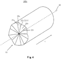
- FIG. 4 illustrates a light guide device 100c according to another embodiment of the present invention.
- the light incident face 20a has a first edge 21a and a second edge 22a.
- the light incident face 20b has a first edge 21b and a second edge 22b.
- first edges 21a, 21b and the second edges 22a, 22b are defined in the clockwise direction, i.e., in each of the light incident faces, the first edges 21a, 21b are located upstream of the second edges 22a, 22b (alternatively, the first edges 21a, 21b and the second edges 22a, 22b may also be defined in the anti-clockwise direction, and the details will be omitted here).
- first edges 21a, 21b and the second edges 22a, 22b may also be defined in the anti-clockwise direction, and the details will be omitted here).
- the first edge 21a of the light incident face 20a is displaced with respect to the second edge 22a towards outside of the light guide device 100c in the direction along the axis 30 of the light guide device 100c
- the first edge 21b of the light incident face 20b is displaced with respect to the second edge 22b towards inside of the light guide device 100c in the direction along the axis 30 of the light guide device 100c. That is, the displacement of the light incident face 20a with respect to the axis 30 of the light guide device 100c is in a direction opposite to the direction in which the light incident face 20b is displaced with respect to the axis 30 of the light guide device 100c.
- the light incident faces 20a and 20b in light guide device 100c may be divided into two groups.
- the first edges 21a of the first group of light incident faces 20a are displaced with respect to the second edges 22a towards the inside of the light guide device 100c along an axis of light guide device 100c, while the first edges 21b of the second group of light incident faces 20b are displaced with respect to the second edges 22b towards outside of the light guide device 100c along the axis of the light guide device 100c.
- the first group of light incident faces 20a and the second group of light incident faces 20b are alternately distributed in a direction about the axis of the light guide device 100c.
- the first edge 22a of the light incident face 20a and the first edge 21b of light incident face 20b that are adjacent to each other may be coincident with each other, thereby avoiding the presence of any steps between adjacent light incident faces.
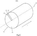
- FIG. 5 illustrates a light guide device 100d according to yet another embodiment of the present invention.
- the light incident end 10 is provided with only one light incident face 20 which is a curved surface extending between the first edge 21 and the second edge 22, for example, a smooth curved surface. This approach may be helpful to molding process of the light guide device.
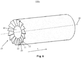
- FIG. 6 illustrates a light guide device 100e according to a further embodiment of the present invention.
- the light incident end 10 further includes a central light transmission planar face 40 positioned at a central position of the light incident end 10 and perpendicular to the axis 30 of the light guide device 100e.
- At least one light incident face 20 is disposed at the periphery of the central light transmission planar face 40.
- the central light transmission planar face 40 may be used to control the energy distribution of the incident light in various directions after the incident light enters the light guide device 100e. The energy distribution may be achieved by adjusting size of the area of the central light transmission planar face 40.
- the incident light faces 20, 20', 20a, and 20b may be planar or curved.
- the light incident faces 20, 20', 20a and 20b may extend smoothly between the first edges 21, 21a, 21b and the second edges 22, 22a, 22b.
- the first edges 21, 21a, 21b and the second edges 22, 22a, 22b may extend from the periphery of the light incident end 10 towards the center of the light incident end 10.
- the first edges 21, 21a, 21b and the second edges 22, 22a, 22b may converge into one point at the center of the light incident end 10, as shown in FIG. 1 , FIG. 3 and FIG. 4 , or may extend to the central light transmission planar face 40, as shown in FIG. 6 .
- the number of the light incident faces 20, 20', 20a and 20b may be any number greater than or equal to one.
- increasing the number of the light incident faces 20, 20', 20a and 20b may advantageously improve coupling effect (increased brightness uniformity) of the incident light, while the reduction in the number of the incident light faces 20, 20', 20a and 20b is beneficial to reduce the processing difficulty.
- the number of the incident light faces 20, 20', 20a and 20b may be 8 to 16, such as 10 to 12.
- the light incident faces 20, 20', 20a, and 20b may have a sector shape. This may facilitate fully utilizing the area of the light incident end 10.
- each of the light guide devices 100a, 100b, 100c, 100d and 100e described above in the examples shown in FIGS. 1-6 has circular cross section
- the embodiments of the present invention are not limited to this, and the light guide device may have any cross-sectional shape known in the art.
- it may also have a cross-sectional shape of square, polygon, etc., as long as the light coupled into the light guide device from the light incident end 10 still satisfies the requirements for light transmission by light guide device such as total reflection conditions to achieve the desired function.
- the light incident faces 20, 20', 20a and 20b in the light guide device in the embodiment of the present invention still require the light entering the light guide device through these light incident faces to meet the total reflection condition of the light guide device, and the specific directions of the light incident faces 20, 20', 20a and 20b may be determined according to parameters such as material refractive index of the light guide device.
- light incident faces 20, 20', 20a, and 20b may generally be inclined at an angle greater than 0 degrees and less than 25 degrees with respect to the cross-section of the light guide device perpendicular to the axis 30.
- embodiments of the present invention are not limited to this.
- the offset S between the first edge 21, 21a and 21b and the second edge 22, 22a and 22b of the light incident face 20, 20', 20a and 20b along the axis 30 is 1 mm to 3 mm, e.g., 1.5 mm at the periphery of the light incident end 10.
- the light incident faces 20, 20', 20a and 20b may be fabricated by performing a variety of molding processes known in the art on the light incident end 10 of each of the light guide devices 100a, 100b, 100c, 100d and 100e.
- the light guide devices 100a, 100b, 100c, 100d, and 100e may be made from a transparent glass, resin or plastic material, such as PMMA (polymethyl methacrylate) or polycarbonate.
- the light guide devices 100a, 100b, 100c, 100d, and 100e may be supported or suspended by any known suitable means for holding optical elements, such as a support, a boom, etc.
- the invention also provides a lighting apparatus including the light guide device 100a, 100b, 100c, 100d, and 100e as described in any of the preceding embodiments.
- the lighting apparatus may include, for example, a vehicle light of any motor vehicle.
- the invention also provides a motor vehicle including the lighting apparatus including the light guide device 100a, 100b, 100c, 100d, and 100e as previously described.
Landscapes
- Physics & Mathematics (AREA)
- General Physics & Mathematics (AREA)
- Optics & Photonics (AREA)
- Planar Illumination Modules (AREA)
- Light Guides In General And Applications Therefor (AREA)
Abstract
Description
- The present invention relates to a light guide device, a lighting apparatus and a motor vehicle.
- A light guide device refers to a device for guiding light in which the light travels primarily by total reflection. The light guide device is widely used in the fields of lighting, light transmission, and the like. It may have various shapes, of such as a cylinder (referred to as a light guide rod), an elongated shape (referred to as a light guide bar, a light bar), a plate shape (referred to as a light guide plate), a ring (referred to as a light guide ring), and the like. The light guide device may generally receive an incident light at its end thereof and conduct light to another end of the light guide device or any desired exit position by the total reflection of its outer wall. Generally, the incident end face of the light guide device is a planar structure of such as a circle, or a square. The light guide device may be used, for example, in a lighting device for conducting light emitted by the light source to a desired position.
- It is an object of the present invention to provide a light guide device that can increase the uniformity and efficiency of incident light coupling of the light guide device. The present invention also provides an illumination apparatus including the light guide device and a motor vehicle including the lighting apparatus.
- An embodiment of the present invention provides a light guide device comprising: a light incident end configured to receive an incident light, wherein the light incident end has at least one light incident face and each light incident face has a first edge and a second edge that are displaced from each other in a direction along an axis of the light guide device.
- In an embodiment, the light incident end has one light incident face which is a curved face extending between the first edge and the second edge.
- In an embodiment, the light incident end has a plurality of the light incident faces arranged in a direction about the axis of the light guide device.
- In an embodiment, the first edge is located at upstream of the second edge in each of the light incident faces in a clockwise or anti-clockwise direction about the axis of the light guide device, and the first edge is displaced towards inside of the light guide device in the direction along the axis of the light guide device, with respect to the second edge in each of the light incident faces.
- In an embodiment, the first edge is located at upstream of the second edge in each of the light incident faces in a clockwise or anti-clockwise direction about the axis of the light guide device, and the first edge is displaced towards outside of the light guide device in the direction along the axis of the light guide device, with respect to the second edge in each of the light incident faces.
- In an embodiment, the first edge is located at upstream of the second edge in each of the light incident faces in a clockwise or anti-clockwise direction about the axis of the light guide device, and the light incident faces are divided into a first group of the light incident faces and a second group of the light incident faces, and
wherein the first edge is displaced towards inside of the light guide device in the direction along the axis of the light guide device, with respect to the second edge in each of the first group of the light incident faces, and
wherein the first edge is displaced towards outside of the light guide device in the direction along the axis of the light guide device, with respect to the second edge in each of the second group of the light incident faces. - In an embodiment, the first group of the light incident faces and the second group of the light incident faces are arranged alternately in the direction about the axis of the light guide device.
- In an embodiment, the light incident faces are planar faces or curved faces.
- In an embodiment, the first edge and the second edge extend from a periphery of the light incident end towards a center of the light incident end.
- In an embodiment, the light incident end further comprises a central light transmission planar face which is located at a central position of the light incident end and is perpendicular to the axis of the light guide device, the at least one light incident face being arranged around the central light transmission planar face.
- In an embodiment, the number of the light incident faces is from 8 to 16.
- In an embodiment, the light incident faces have shapes of sector.
- An embodiment of the present invention also provides a lighting apparatus comprising the light guide device as described above.
- An embodiment of the present invention also provides a motor vehicle comprising the lighting apparatus as described above.
- In the light guide device of at least one embodiment of the present invention described in the above, a plurality of light incident faces that are tilted or twisted relative to the axis of the light guide device, are provided at the light incident end, thus uniformity and optical efficiency of the brightness distribution can be improved.
-
-
FIG. 1 schematically shows a light guide device according to an embodiment of the present invention; -
FIG. 2 schematically shows a side view of the light guide device shown inFIG. 1 ; -
FIG. 3 schematically shows a light guide device according to another embodiment of the present invention; -
FIG. 4 schematically shows a light guide device according to yet another embodiment of the present invention; -
FIG. 5 schematically shows a light guide device according to a further embodiment of the present invention; and -
FIG. 6 schematically shows a light guide device according to another embodiment of the present invention. - The technical solutions of the invention are further explained in detail by way of examples, with reference to the accompanying drawings. In the specification, like or similar reference numbers indicate like or similar parts. The following description of embodiments of the present invention with reference to the accompanying drawings is intended to explain the general inventive concepts of the invention and should not be construed as limiting the invention.
- According to the general inventive concept of the present invention, it provides a light guide device including: a light incident end configured to receive an incident light, wherein the light incident end has at least one light incident face and each light incident face has a first edge and a second edge that are displaced from each other in a direction along an axis of the light guide device.
- Further, in the following detailed description, numerous specific details are set forth in order to provide a thorough understanding of the embodiments of the present disclosure. It will be apparent, however, that one or more embodiments may also be practiced without these specific details.
-
FIG. 1 andFIG. 2 schematically illustrate alight guide device 100a according to an embodiment of the present invention. Thelight guide device 100a includes alight incident end 10 for receiving an incident light. Thelight incident end 10 is provided with a plurality of light incident faces 20. Each of these light incident faces 20 has afirst edge 21 and asecond edge 22 displaced from one another in a direction along anaxis 30 of thelight guide device 100a. Thelight incident face 20 extends between thefirst edge 21 and thesecond edge 22. For example, thelight incident face 20 may be formed by a base line sweeping from thefirst edge 21 to thesecond edge 22. Thefirst edge 21 andsecond edge 22 are displaced from one another in the direction along theaxis 30. It means that theincident light surface 20 is not perpendicular to theaxis 30 of thelight guide device 100a, but is generally tilted or twisted relative to theaxis 30 of thelight guide device 100a. This tilting or twisting causes the incident light to have different behavior after entering the light guide device from thelight incident end 10, in comparison with the light in the conventional light guide devices. - In conventional light guide devices, the incident end surface of the light guide device is entirely in a form of a planar structure such as a circle or a square. Thus, the incident light is continuously reflected by sidewalls of the light guide device all along substantially in a plane including the axis of the light guide device, after the incident light enters the light guide device from the incident end surface. In contrast, in the
light guide device 100a in accordance with the embodiment of the present invention, the plurality of light incident faces 20 are each generally angled or twisted relative to theaxis 30 of thelight guide device 100a, which allows the incident light to have a more uniform light intensity distribution after entering thelight guide device 100a from thelight incident end 10, thereby improving optical efficiency. - It should be noted that the phrase "the first and second edges displaced from each other in the direction along the axis" does not mean that the
first edge 21 and thesecond edge 22 must be displaced from one another in parallel, but rather, meaning that thefirst edge 21 and thesecond edge 22 do not coincide with each other in the direction along the axis such that thelight incident face 20 is not perpendicular to theaxis 30 of thelight guide device 100a. Thefirst edge 21 and thesecond edge 22 may be edges adjacent to each other (as shown inFIG. 1 ), or may be non-adjacent edges (as shown inFIG. 6 ), or may also be substantially parallel (as shown inFIG. 5 ). InFIG. 2 , the offset S of thefirst edge 21 and thesecond edge 22 along theaxis 30 at a periphery of the light incident end 10 (thefirst edge 21 is blocked inFIG. 2 and only one end point of thefirst edge 21 is shown). In the example ofFIG. 2 , thelight incident face 20 is curved, which may allow the incident direction of the incident light at thelight incident end 10 to be more diverse. It is not necessary, however, for example, the light incident face 20' may also be a plane, as in the example of thelight guide device 100b shown inFIG. 3 . - By way of example, a plurality of light incident faces 20, 20' may be arranged along a direction about the
axis 30 oflight guide device axis 30 of thelight guide device 100a. - By way of example, in the
light guide device first edges 21 with respect to the correspondingsecond edges 22 in all the light incident faces 20, 20' may be in the same direction. - In the example of
FIGS. 1-3 , in each of the light incident faces 20, 20', thefirst edge 21 is positioned upstream of thesecond edge 22 along the clockwise direction about the axis of thelight guide device first edge 21 of each of the light incident faces 20, 20' is displaced with respect to thesecond edge 22 towards an interior of thelight guide device FIG. 1 to FIG. 3 ), along theaxis 30 of thelight guide device - In another example, the first edge may also be displaced towards outside of the light guide device (e.g., in the opposite direction to the direction x) with respect to the second edge. And specifically, in each of the light incident faces, the first edge is located upstream of the second edge along the clockwise or anti-clockwise direction about the axis of the light guide device, and the first edge of each of the incident light faces is displaced with respect to the second edge towards outside of the light guide device along the axis of the light guide device.
- By way of example, since there may be a position difference between adjacent light incident faces 20, 20 ', the adjacent light incident faces 20, 20' may be connected by a
step surface 23. Thestep surface 23 may not be used to receive the incident light. - By way of example, in light guide device, the displacements of the
first edges 21 with respect to thesecond edges 22 in all the light incident faces may not be in the same direction. In particular, in each of the light incident faces, the first edge is located upstream of the second edge along the clockwise or anti-clockwise direction about the axis of the light guide device. In some of the light incident faces (a first set of light incident faces), the first edges are displaced with respect to the second edges toward the interior of the light guide device along the axis of the light guide device, and in others of the light incident faces (a second set of light incident faces), the first edges are displaced with respect to the second edges towards outside of the light guide device along the axis of the light guide device. -
FIG. 4 illustrates alight guide device 100c according to another embodiment of the present invention. In thelight guide device 100c, two adjacent light incident faces 20a and 20b are shown. Thelight incident face 20a has afirst edge 21a and asecond edge 22a. Thelight incident face 20b has afirst edge 21b and asecond edge 22b. For ease of description, thefirst edges second edges first edges second edges first edges second edges FIG. 4 , thefirst edge 21a of thelight incident face 20a is displaced with respect to thesecond edge 22a towards outside of thelight guide device 100c in the direction along theaxis 30 of thelight guide device 100c, and thefirst edge 21b of thelight incident face 20b is displaced with respect to thesecond edge 22b towards inside of thelight guide device 100c in the direction along theaxis 30 of thelight guide device 100c. That is, the displacement of thelight incident face 20a with respect to theaxis 30 of thelight guide device 100c is in a direction opposite to the direction in which thelight incident face 20b is displaced with respect to theaxis 30 of thelight guide device 100c. To this end, the light incident faces 20a and 20b inlight guide device 100c may be divided into two groups. Thefirst edges 21a of the first group of light incident faces 20a are displaced with respect to thesecond edges 22a towards the inside of thelight guide device 100c along an axis oflight guide device 100c, while thefirst edges 21b of the second group of light incident faces 20b are displaced with respect to thesecond edges 22b towards outside of thelight guide device 100c along the axis of thelight guide device 100c. In this example, the first group of light incident faces 20a and the second group of light incident faces 20b are alternately distributed in a direction about the axis of thelight guide device 100c. - In the above arrangement, as an example, the
first edge 22a of thelight incident face 20a and thefirst edge 21b oflight incident face 20b that are adjacent to each other may be coincident with each other, thereby avoiding the presence of any steps between adjacent light incident faces. -
FIG. 5 illustrates alight guide device 100d according to yet another embodiment of the present invention. In thelight guide device 100d, thelight incident end 10 is provided with only onelight incident face 20 which is a curved surface extending between thefirst edge 21 and thesecond edge 22, for example, a smooth curved surface. This approach may be helpful to molding process of the light guide device. -
FIG. 6 illustrates alight guide device 100e according to a further embodiment of the present invention. In thelight guide device 100e, thelight incident end 10 further includes a central light transmissionplanar face 40 positioned at a central position of thelight incident end 10 and perpendicular to theaxis 30 of thelight guide device 100e. At least onelight incident face 20 is disposed at the periphery of the central light transmissionplanar face 40. The central light transmissionplanar face 40 may be used to control the energy distribution of the incident light in various directions after the incident light enters thelight guide device 100e. The energy distribution may be achieved by adjusting size of the area of the central light transmissionplanar face 40. - In embodiments of the present invention, the incident light faces 20, 20', 20a, and 20b may be planar or curved. The light incident faces 20, 20', 20a and 20b may extend smoothly between the
first edges - In an embodiment of the present invention, the
first edges light incident end 10 towards the center of thelight incident end 10. By way of example, thefirst edges light incident end 10, as shown inFIG. 1 ,FIG. 3 andFIG. 4 , or may extend to the central light transmissionplanar face 40, as shown inFIG. 6 . - In embodiments of the present invention, the number of the light incident faces 20, 20', 20a and 20b may be any number greater than or equal to one. In general, increasing the number of the light incident faces 20, 20', 20a and 20b may advantageously improve coupling effect (increased brightness uniformity) of the incident light, while the reduction in the number of the incident light faces 20, 20', 20a and 20b is beneficial to reduce the processing difficulty. Considering the balance between them, such as the number of the incident light faces 20, 20', 20a and 20b may be 8 to 16, such as 10 to 12.
- In one embodiment, the light incident faces 20, 20', 20a, and 20b may have a sector shape. This may facilitate fully utilizing the area of the
light incident end 10. - Although the main body of each of the
light guide devices FIGS. 1-6 has circular cross section, however, the embodiments of the present invention are not limited to this, and the light guide device may have any cross-sectional shape known in the art. For example, it may also have a cross-sectional shape of square, polygon, etc., as long as the light coupled into the light guide device from thelight incident end 10 still satisfies the requirements for light transmission by light guide device such as total reflection conditions to achieve the desired function. - Since the light guide device needs to conduct the light incident from the light incident end by the total reflection, it will be appreciated by those skilled in the art that the light incident faces 20, 20', 20a and 20b in the light guide device in the embodiment of the present invention still require the light entering the light guide device through these light incident faces to meet the total reflection condition of the light guide device, and the specific directions of the light incident faces 20, 20', 20a and 20b may be determined according to parameters such as material refractive index of the light guide device. For example, light incident faces 20, 20', 20a, and 20b may generally be inclined at an angle greater than 0 degrees and less than 25 degrees with respect to the cross-section of the light guide device perpendicular to the
axis 30. However, embodiments of the present invention are not limited to this. - By way of example, the offset S between the
first edge second edge light incident face axis 30 is 1 mm to 3 mm, e.g., 1.5 mm at the periphery of thelight incident end 10. - By way of example, the light incident faces 20, 20', 20a and 20b may be fabricated by performing a variety of molding processes known in the art on the
light incident end 10 of each of thelight guide devices - By way of example, the
light guide devices - The
light guide devices - The invention also provides a lighting apparatus including the
light guide device - The invention also provides a motor vehicle including the lighting apparatus including the
light guide device - While the invention has been described in connection with the accompanying drawings, embodiments disclosed in the drawings are intended to illustrate the preferred embodiments of the invention and are not to be construed as limiting the invention. The scales in the drawings are merely illustrative and are not to be construed as limiting the invention.
- While some embodiments of the general inventive concept have been shown and described, those skilled in the art will appreciate that changes may be made to these embodiments without departing from the principles and spirit of the general inventive concept. The scope of the present invention is defined in the appended claims and their equivalents.
Claims (14)
- A light guide device (100a, 100b, 100c, 100d, 100e) comprising:a light incident end (10) configured to receive an incident light,wherein the light incident end (10) has at least one light incident face (20, 20', 20a, 20b) and each light incident face has a first edge (21, 21a, 21b) and a second edge (22, 22a, 22b) that are displaced from each other in a direction along an axis (30) of the light guide device (100a, 100b, 100c, 100d, 100e).
- The light guide device (100d) according to claim 1, wherein the light incident end (10) has one light incident face (20) which is a curved face extending between the first edge (21) and the second edge (22).
- The light guide device (100a,100b, 100c, 100e) according to claim 1, wherein the light incident end (10) has a plurality of the light incident faces (20, 20', 20a, 20b) arranged in a direction about the axis (30) of the light guide device (100a,100b, 100c, 100e).
- The light guide device (100a,100b) according to claim 3, wherein the first edge (21) is located at upstream of the second edge (22) in each of the light incident faces (20, 20') in a clockwise or anti-clockwise direction about the axis (30) of the light guide device (100a,100b), and the first edge (21) is displaced towards inside of the light guide device (100a,100b) in the direction along the axis (30) of the light guide device (100a,100b), with respect to the second edge (22) in each of the light incident faces (20, 20').
- The light guide device (100a,100b) according to claim 3, wherein the first edge (21) is located at upstream of the second edge (22) in each of the light incident faces (20, 20') in a clockwise or anti-clockwise direction about the axis (30) of the light guide device (100a,100b), and the first edge (21) is displaced towards outside of the light guide device (100a,100b) in the direction along the axis (30) of the light guide device (100a,100b), with respect to the second edge (22) in each of the light incident faces (20, 20').
- The light guide device (100c) according to claim 3, wherein the first edge (21a, 21b) is located at upstream of the second edge (22a, 22b) in each of the light incident faces (20a, 20b) in a clockwise or anti-clockwise direction about the axis (30) of the light guide device (100c), and the light incident faces (20a, 20b) are divided into a first group of the light incident faces (20a) and a second group of the light incident faces (20b), and
wherein the first edge (21a) is displaced towards inside of the light guide device (100c) in the direction along the axis (30) of the light guide device (100c), with respect to the second edge (22a) in each of the first group of the light incident faces (20a), and
wherein the first edge (21b) is displaced towards outside of the light guide device (100c) in the direction along the axis (30) of the light guide device (100c), with respect to the second edge (22b) in each of the second group of the light incident faces (20b). - The light guide device (100c) according to claim 6, wherein the first group of the light incident faces (20a) and the second group of the light incident faces (20b) are arranged alternately in the direction about the axis (30) of the light guide device (100c).
- The light guide device (100a, 100b, 100c, 100e) according to any one of claims 1 and 3 to 6, wherein the light incident faces (20, 20', 20a, 20b) are planar faces or curved faces.
- The light guide device (100a, 100b, 100c, 100d, 100e) according to any one of claims 1 to 6, wherein the first edge (21, 21a, 21b) and the second edge (22, 22a, 22b) extend from a periphery of the light incident end (10) towards a center of the light incident end (10).
- The light guide device (100e) according to any one of claims 1 to 6, wherein the light incident end (10) further comprises a central light transmission planar face (40) which is located at a central position of the light incident end (10) and is perpendicular to the axis (30) of the light guide device (100e), the at least one light incident face (20) being arranged around the central light transmission planar face (40).
- The light guide device (100a, 100b, 100c, 100e) according to any one of claims 3 to 6, wherein the number of the light incident faces (20, 20', 20a, 20b) is from 8 to 16.
- The light guide device (100a, 100b, 100c, 100e) according to any one of claims 3 to 6, wherein the light incident faces (20, 20', 20a, 20b) have shapes of sector.
- A lighting apparatus comprising the light guide device (100a, 100b, 100c, 100d, 100e) according to any one of claims 1 to 12.
- A motor vehicle comprising the lighting apparatus according to claim 13.
Applications Claiming Priority (1)
| Application Number | Priority Date | Filing Date | Title |
|---|---|---|---|
| CN201710451453.XA CN109143449B (en) | 2017-06-15 | 2017-06-15 | Light guide device, lighting device and motor vehicle |
Publications (2)
| Publication Number | Publication Date |
|---|---|
| EP3415814A1 true EP3415814A1 (en) | 2018-12-19 |
| EP3415814B1 EP3415814B1 (en) | 2023-09-27 |
Family
ID=62748714
Family Applications (1)
| Application Number | Title | Priority Date | Filing Date |
|---|---|---|---|
| EP18177469.6A Active EP3415814B1 (en) | 2017-06-15 | 2018-06-13 | Light guide device, lighting apparatus and motor vehicle |
Country Status (3)
| Country | Link |
|---|---|
| US (1) | US10317603B2 (en) |
| EP (1) | EP3415814B1 (en) |
| CN (1) | CN109143449B (en) |
Cited By (1)
| Publication number | Priority date | Publication date | Assignee | Title |
|---|---|---|---|---|
| IT202100008030A1 (en) * | 2021-03-31 | 2022-10-01 | Marelli Automotive Lighting Italy S P A Con Socio Unico | HYBRID LIGHT GUIDE SYSTEM FOR VEHICLE LIGHTING DEVICES, AND ASSOCIATED LIGHTING DEVICE |
Families Citing this family (1)
| Publication number | Priority date | Publication date | Assignee | Title |
|---|---|---|---|---|
| CN111856641B (en) * | 2019-04-28 | 2024-07-05 | 法雷奥照明湖北技术中心有限公司 | Light guide, light emitting device comprising the light guide and motor vehicle |
Citations (5)
| Publication number | Priority date | Publication date | Assignee | Title |
|---|---|---|---|---|
| US20140071703A1 (en) * | 2012-09-13 | 2014-03-13 | Koito Manufacturing Co., Ltd. | Vehicular lamp |
| US20140204600A1 (en) * | 2013-01-21 | 2014-07-24 | Hella Kgaa Hueck & Co. | Lighting appliance for vehicles |
| US20150241616A1 (en) * | 2014-02-26 | 2015-08-27 | Hella Kgaa Hueck & Co. | Lighting Device for Vehicles |
| WO2016009156A1 (en) * | 2014-07-16 | 2016-01-21 | Valeo Systèmes Thermiques | Lighting device |
| US20160084468A1 (en) * | 2013-06-11 | 2016-03-24 | Koito Manufacturing Co., Ltd. | Vehicular lamp |
Family Cites Families (10)
| Publication number | Priority date | Publication date | Assignee | Title |
|---|---|---|---|---|
| JP2006091821A (en) * | 2004-08-26 | 2006-04-06 | Fuji Photo Film Co Ltd | Prism sheet and display device using the same |
| JP5369359B2 (en) * | 2009-04-13 | 2013-12-18 | スタンレー電気株式会社 | Lamp |
| JP5477812B2 (en) * | 2010-06-18 | 2014-04-23 | 株式会社小糸製作所 | Vehicle lamp |
| TWI497129B (en) * | 2011-01-26 | 2015-08-21 | Hon Hai Prec Ind Co Ltd | Light guiding bar and lighting apparatus having same |
| FR2995977B1 (en) * | 2012-09-26 | 2019-06-28 | Valeo Vision | LIGHT GUIDE FOR A DEVICE FOR LIGHTING AND / OR SIGNALING A MOTOR VEHICLE |
| TWI500985B (en) * | 2013-07-23 | 2015-09-21 | Cheng Tao Lee | Light guide |
| CZ306764B6 (en) * | 2013-09-30 | 2017-06-21 | Varroc Lighting Systems, s.r.o. | A lighting device |
| CN106439735A (en) * | 2015-08-07 | 2017-02-22 | 法雷奥照明湖北技术中心有限公司 | Light guide unit, light guide device and lighting and/or signal indicating device |
| CN106287291B (en) * | 2016-01-26 | 2019-06-14 | 广州市熠芯节能服务有限公司 | LED light guiding lens |
| CN206207259U (en) * | 2016-10-31 | 2017-05-31 | 比亚迪股份有限公司 | A kind of light fixture, vehicle |
-
2017
- 2017-06-15 CN CN201710451453.XA patent/CN109143449B/en active Active
-
2018
- 2018-06-13 EP EP18177469.6A patent/EP3415814B1/en active Active
- 2018-06-15 US US16/009,949 patent/US10317603B2/en active Active
Patent Citations (5)
| Publication number | Priority date | Publication date | Assignee | Title |
|---|---|---|---|---|
| US20140071703A1 (en) * | 2012-09-13 | 2014-03-13 | Koito Manufacturing Co., Ltd. | Vehicular lamp |
| US20140204600A1 (en) * | 2013-01-21 | 2014-07-24 | Hella Kgaa Hueck & Co. | Lighting appliance for vehicles |
| US20160084468A1 (en) * | 2013-06-11 | 2016-03-24 | Koito Manufacturing Co., Ltd. | Vehicular lamp |
| US20150241616A1 (en) * | 2014-02-26 | 2015-08-27 | Hella Kgaa Hueck & Co. | Lighting Device for Vehicles |
| WO2016009156A1 (en) * | 2014-07-16 | 2016-01-21 | Valeo Systèmes Thermiques | Lighting device |
Cited By (2)
| Publication number | Priority date | Publication date | Assignee | Title |
|---|---|---|---|---|
| IT202100008030A1 (en) * | 2021-03-31 | 2022-10-01 | Marelli Automotive Lighting Italy S P A Con Socio Unico | HYBRID LIGHT GUIDE SYSTEM FOR VEHICLE LIGHTING DEVICES, AND ASSOCIATED LIGHTING DEVICE |
| EP4067733A1 (en) * | 2021-03-31 | 2022-10-05 | Marelli Automotive Lighting Italy S.p.A. Con Socio Unico | Light guide hybrid system for lighting devices for vehicles, and associated lighting device |
Also Published As
| Publication number | Publication date |
|---|---|
| EP3415814B1 (en) | 2023-09-27 |
| CN109143449A (en) | 2019-01-04 |
| US10317603B2 (en) | 2019-06-11 |
| US20180364406A1 (en) | 2018-12-20 |
| CN109143449B (en) | 2021-03-26 |
Similar Documents
| Publication | Publication Date | Title |
|---|---|---|
| US9519095B2 (en) | Optical waveguides | |
| EP2306076A1 (en) | Plane light source device and display device | |
| US20130250609A1 (en) | Light guide illumination devices | |
| CN104115046B (en) | For method, optical system and lighting device that light is homogenized | |
| US9459396B1 (en) | Linear indirect LED lighting system | |
| EP3415814B1 (en) | Light guide device, lighting apparatus and motor vehicle | |
| CN105393051A (en) | Lightguides | |
| CN108375043B (en) | Beam shaping devices, optical assemblies and lighting and/or signaling devices | |
| EP3163157B1 (en) | Light guiding unit, light guiding device, and lighting and/or signal indicating device | |
| US11255511B2 (en) | Optical device for modifying light distribution | |
| CN211698258U (en) | Refraction type lens and display device | |
| RU2638822C2 (en) | Lighting device based on light guide with light-scattering particles and light angle selection module | |
| CN110109218A (en) | With the light guide plate of optical microstructures on a kind of lozenges | |
| EP3392557A1 (en) | Light guide device | |
| EP3278013B1 (en) | Lighting system using a lightguide. | |
| CN114563839A (en) | Light guide element and backlight module | |
| KR101463414B1 (en) | Lighting emitting optical device | |
| US20200116326A1 (en) | Optical lens for vehicle and vehicle lamp using the same | |
| CN221629585U (en) | Optical lens, lens assembly and lamp | |
| WO2013088295A1 (en) | Optical element and method for homogenizing light | |
| CN105508997A (en) | Optical structural plate and LED illuminating device | |
| JP5756382B2 (en) | Lighting device | |
| CN214580894U (en) | Diffusion lens and lighting device | |
| CN210462870U (en) | Light guide structure and lamp | |
| CN109541740B (en) | High-luminous-efficiency round light guide plate and lighting device |
Legal Events
| Date | Code | Title | Description |
|---|---|---|---|
| PUAI | Public reference made under article 153(3) epc to a published international application that has entered the european phase |
Free format text: ORIGINAL CODE: 0009012 |
|
| STAA | Information on the status of an ep patent application or granted ep patent |
Free format text: STATUS: REQUEST FOR EXAMINATION WAS MADE |
|
| 17P | Request for examination filed |
Effective date: 20180613 |
|
| AK | Designated contracting states |
Kind code of ref document: A1 Designated state(s): AL AT BE BG CH CY CZ DE DK EE ES FI FR GB GR HR HU IE IS IT LI LT LU LV MC MK MT NL NO PL PT RO RS SE SI SK SM TR |
|
| AX | Request for extension of the european patent |
Extension state: BA ME |
|
| STAA | Information on the status of an ep patent application or granted ep patent |
Free format text: STATUS: EXAMINATION IS IN PROGRESS |
|
| 17Q | First examination report despatched |
Effective date: 20211122 |
|
| GRAP | Despatch of communication of intention to grant a patent |
Free format text: ORIGINAL CODE: EPIDOSNIGR1 |
|
| STAA | Information on the status of an ep patent application or granted ep patent |
Free format text: STATUS: GRANT OF PATENT IS INTENDED |
|
| INTG | Intention to grant announced |
Effective date: 20230421 |
|
| P01 | Opt-out of the competence of the unified patent court (upc) registered |
Effective date: 20230602 |
|
| GRAS | Grant fee paid |
Free format text: ORIGINAL CODE: EPIDOSNIGR3 |
|
| GRAA | (expected) grant |
Free format text: ORIGINAL CODE: 0009210 |
|
| STAA | Information on the status of an ep patent application or granted ep patent |
Free format text: STATUS: THE PATENT HAS BEEN GRANTED |
|
| AK | Designated contracting states |
Kind code of ref document: B1 Designated state(s): AL AT BE BG CH CY CZ DE DK EE ES FI FR GB GR HR HU IE IS IT LI LT LU LV MC MK MT NL NO PL PT RO RS SE SI SK SM TR |
|
| REG | Reference to a national code |
Ref country code: GB Ref legal event code: FG4D |
|
| REG | Reference to a national code |
Ref country code: CH Ref legal event code: EP |
|
| REG | Reference to a national code |
Ref country code: DE Ref legal event code: R096 Ref document number: 602018058152 Country of ref document: DE |
|
| REG | Reference to a national code |
Ref country code: IE Ref legal event code: FG4D |
|
| REG | Reference to a national code |
Ref country code: LT Ref legal event code: MG9D |
|
| PG25 | Lapsed in a contracting state [announced via postgrant information from national office to epo] |
Ref country code: GR Free format text: LAPSE BECAUSE OF FAILURE TO SUBMIT A TRANSLATION OF THE DESCRIPTION OR TO PAY THE FEE WITHIN THE PRESCRIBED TIME-LIMIT Effective date: 20231228 |
|
| PG25 | Lapsed in a contracting state [announced via postgrant information from national office to epo] |
Ref country code: SE Free format text: LAPSE BECAUSE OF FAILURE TO SUBMIT A TRANSLATION OF THE DESCRIPTION OR TO PAY THE FEE WITHIN THE PRESCRIBED TIME-LIMIT Effective date: 20230927 Ref country code: RS Free format text: LAPSE BECAUSE OF FAILURE TO SUBMIT A TRANSLATION OF THE DESCRIPTION OR TO PAY THE FEE WITHIN THE PRESCRIBED TIME-LIMIT Effective date: 20230927 Ref country code: NO Free format text: LAPSE BECAUSE OF FAILURE TO SUBMIT A TRANSLATION OF THE DESCRIPTION OR TO PAY THE FEE WITHIN THE PRESCRIBED TIME-LIMIT Effective date: 20231227 Ref country code: LV Free format text: LAPSE BECAUSE OF FAILURE TO SUBMIT A TRANSLATION OF THE DESCRIPTION OR TO PAY THE FEE WITHIN THE PRESCRIBED TIME-LIMIT Effective date: 20230927 Ref country code: LT Free format text: LAPSE BECAUSE OF FAILURE TO SUBMIT A TRANSLATION OF THE DESCRIPTION OR TO PAY THE FEE WITHIN THE PRESCRIBED TIME-LIMIT Effective date: 20230927 Ref country code: HR Free format text: LAPSE BECAUSE OF FAILURE TO SUBMIT A TRANSLATION OF THE DESCRIPTION OR TO PAY THE FEE WITHIN THE PRESCRIBED TIME-LIMIT Effective date: 20230927 Ref country code: GR Free format text: LAPSE BECAUSE OF FAILURE TO SUBMIT A TRANSLATION OF THE DESCRIPTION OR TO PAY THE FEE WITHIN THE PRESCRIBED TIME-LIMIT Effective date: 20231228 Ref country code: FI Free format text: LAPSE BECAUSE OF FAILURE TO SUBMIT A TRANSLATION OF THE DESCRIPTION OR TO PAY THE FEE WITHIN THE PRESCRIBED TIME-LIMIT Effective date: 20230927 |
|
| REG | Reference to a national code |
Ref country code: NL Ref legal event code: MP Effective date: 20230927 |
|
| REG | Reference to a national code |
Ref country code: AT Ref legal event code: MK05 Ref document number: 1615734 Country of ref document: AT Kind code of ref document: T Effective date: 20230927 |
|
| PG25 | Lapsed in a contracting state [announced via postgrant information from national office to epo] |
Ref country code: NL Free format text: LAPSE BECAUSE OF FAILURE TO SUBMIT A TRANSLATION OF THE DESCRIPTION OR TO PAY THE FEE WITHIN THE PRESCRIBED TIME-LIMIT Effective date: 20230927 |
|
| PG25 | Lapsed in a contracting state [announced via postgrant information from national office to epo] |
Ref country code: IS Free format text: LAPSE BECAUSE OF FAILURE TO SUBMIT A TRANSLATION OF THE DESCRIPTION OR TO PAY THE FEE WITHIN THE PRESCRIBED TIME-LIMIT Effective date: 20240127 |
|
| PG25 | Lapsed in a contracting state [announced via postgrant information from national office to epo] |
Ref country code: AT Free format text: LAPSE BECAUSE OF FAILURE TO SUBMIT A TRANSLATION OF THE DESCRIPTION OR TO PAY THE FEE WITHIN THE PRESCRIBED TIME-LIMIT Effective date: 20230927 |
|
| PG25 | Lapsed in a contracting state [announced via postgrant information from national office to epo] |
Ref country code: ES Free format text: LAPSE BECAUSE OF FAILURE TO SUBMIT A TRANSLATION OF THE DESCRIPTION OR TO PAY THE FEE WITHIN THE PRESCRIBED TIME-LIMIT Effective date: 20230927 |
|
| PG25 | Lapsed in a contracting state [announced via postgrant information from national office to epo] |
Ref country code: SM Free format text: LAPSE BECAUSE OF FAILURE TO SUBMIT A TRANSLATION OF THE DESCRIPTION OR TO PAY THE FEE WITHIN THE PRESCRIBED TIME-LIMIT Effective date: 20230927 Ref country code: RO Free format text: LAPSE BECAUSE OF FAILURE TO SUBMIT A TRANSLATION OF THE DESCRIPTION OR TO PAY THE FEE WITHIN THE PRESCRIBED TIME-LIMIT Effective date: 20230927 Ref country code: IS Free format text: LAPSE BECAUSE OF FAILURE TO SUBMIT A TRANSLATION OF THE DESCRIPTION OR TO PAY THE FEE WITHIN THE PRESCRIBED TIME-LIMIT Effective date: 20240127 Ref country code: ES Free format text: LAPSE BECAUSE OF FAILURE TO SUBMIT A TRANSLATION OF THE DESCRIPTION OR TO PAY THE FEE WITHIN THE PRESCRIBED TIME-LIMIT Effective date: 20230927 Ref country code: EE Free format text: LAPSE BECAUSE OF FAILURE TO SUBMIT A TRANSLATION OF THE DESCRIPTION OR TO PAY THE FEE WITHIN THE PRESCRIBED TIME-LIMIT Effective date: 20230927 Ref country code: CZ Free format text: LAPSE BECAUSE OF FAILURE TO SUBMIT A TRANSLATION OF THE DESCRIPTION OR TO PAY THE FEE WITHIN THE PRESCRIBED TIME-LIMIT Effective date: 20230927 Ref country code: AT Free format text: LAPSE BECAUSE OF FAILURE TO SUBMIT A TRANSLATION OF THE DESCRIPTION OR TO PAY THE FEE WITHIN THE PRESCRIBED TIME-LIMIT Effective date: 20230927 Ref country code: SK Free format text: LAPSE BECAUSE OF FAILURE TO SUBMIT A TRANSLATION OF THE DESCRIPTION OR TO PAY THE FEE WITHIN THE PRESCRIBED TIME-LIMIT Effective date: 20230927 Ref country code: PT Free format text: LAPSE BECAUSE OF FAILURE TO SUBMIT A TRANSLATION OF THE DESCRIPTION OR TO PAY THE FEE WITHIN THE PRESCRIBED TIME-LIMIT Effective date: 20240129 |
|
| PG25 | Lapsed in a contracting state [announced via postgrant information from national office to epo] |
Ref country code: PL Free format text: LAPSE BECAUSE OF FAILURE TO SUBMIT A TRANSLATION OF THE DESCRIPTION OR TO PAY THE FEE WITHIN THE PRESCRIBED TIME-LIMIT Effective date: 20230927 Ref country code: IT Free format text: LAPSE BECAUSE OF FAILURE TO SUBMIT A TRANSLATION OF THE DESCRIPTION OR TO PAY THE FEE WITHIN THE PRESCRIBED TIME-LIMIT Effective date: 20230927 |
|
| REG | Reference to a national code |
Ref country code: DE Ref legal event code: R097 Ref document number: 602018058152 Country of ref document: DE |
|
| PG25 | Lapsed in a contracting state [announced via postgrant information from national office to epo] |
Ref country code: DK Free format text: LAPSE BECAUSE OF FAILURE TO SUBMIT A TRANSLATION OF THE DESCRIPTION OR TO PAY THE FEE WITHIN THE PRESCRIBED TIME-LIMIT Effective date: 20230927 |
|
| PG25 | Lapsed in a contracting state [announced via postgrant information from national office to epo] |
Ref country code: DK Free format text: LAPSE BECAUSE OF FAILURE TO SUBMIT A TRANSLATION OF THE DESCRIPTION OR TO PAY THE FEE WITHIN THE PRESCRIBED TIME-LIMIT Effective date: 20230927 |
|
| PLBE | No opposition filed within time limit |
Free format text: ORIGINAL CODE: 0009261 |
|
| STAA | Information on the status of an ep patent application or granted ep patent |
Free format text: STATUS: NO OPPOSITION FILED WITHIN TIME LIMIT |
|
| 26N | No opposition filed |
Effective date: 20240628 |
|
| PG25 | Lapsed in a contracting state [announced via postgrant information from national office to epo] |
Ref country code: SI Free format text: LAPSE BECAUSE OF FAILURE TO SUBMIT A TRANSLATION OF THE DESCRIPTION OR TO PAY THE FEE WITHIN THE PRESCRIBED TIME-LIMIT Effective date: 20230927 |
|
| PG25 | Lapsed in a contracting state [announced via postgrant information from national office to epo] |
Ref country code: SI Free format text: LAPSE BECAUSE OF FAILURE TO SUBMIT A TRANSLATION OF THE DESCRIPTION OR TO PAY THE FEE WITHIN THE PRESCRIBED TIME-LIMIT Effective date: 20230927 |
|
| PG25 | Lapsed in a contracting state [announced via postgrant information from national office to epo] |
Ref country code: BG Free format text: LAPSE BECAUSE OF FAILURE TO SUBMIT A TRANSLATION OF THE DESCRIPTION OR TO PAY THE FEE WITHIN THE PRESCRIBED TIME-LIMIT Effective date: 20230927 |
|
| PG25 | Lapsed in a contracting state [announced via postgrant information from national office to epo] |
Ref country code: BG Free format text: LAPSE BECAUSE OF FAILURE TO SUBMIT A TRANSLATION OF THE DESCRIPTION OR TO PAY THE FEE WITHIN THE PRESCRIBED TIME-LIMIT Effective date: 20230927 |
|
| PG25 | Lapsed in a contracting state [announced via postgrant information from national office to epo] |
Ref country code: MC Free format text: LAPSE BECAUSE OF FAILURE TO SUBMIT A TRANSLATION OF THE DESCRIPTION OR TO PAY THE FEE WITHIN THE PRESCRIBED TIME-LIMIT Effective date: 20230927 |
|
| REG | Reference to a national code |
Ref country code: CH Ref legal event code: PL |
|
| PG25 | Lapsed in a contracting state [announced via postgrant information from national office to epo] |
Ref country code: LU Free format text: LAPSE BECAUSE OF NON-PAYMENT OF DUE FEES Effective date: 20240613 |
|
| GBPC | Gb: european patent ceased through non-payment of renewal fee |
Effective date: 20240613 |
|
| PG25 | Lapsed in a contracting state [announced via postgrant information from national office to epo] |
Ref country code: IE Free format text: LAPSE BECAUSE OF NON-PAYMENT OF DUE FEES Effective date: 20240613 |
|
| PG25 | Lapsed in a contracting state [announced via postgrant information from national office to epo] |
Ref country code: BE Free format text: LAPSE BECAUSE OF NON-PAYMENT OF DUE FEES Effective date: 20240630 Ref country code: CH Free format text: LAPSE BECAUSE OF NON-PAYMENT OF DUE FEES Effective date: 20240630 |
|
| PG25 | Lapsed in a contracting state [announced via postgrant information from national office to epo] |
Ref country code: GB Free format text: LAPSE BECAUSE OF NON-PAYMENT OF DUE FEES Effective date: 20240613 |
|
| REG | Reference to a national code |
Ref country code: BE Ref legal event code: MM Effective date: 20240630 |
|
| PGFP | Annual fee paid to national office [announced via postgrant information from national office to epo] |
Ref country code: DE Payment date: 20250617 Year of fee payment: 8 |
|
| PGFP | Annual fee paid to national office [announced via postgrant information from national office to epo] |
Ref country code: FR Payment date: 20250630 Year of fee payment: 8 |
|
| PG25 | Lapsed in a contracting state [announced via postgrant information from national office to epo] |
Ref country code: CY Free format text: LAPSE BECAUSE OF FAILURE TO SUBMIT A TRANSLATION OF THE DESCRIPTION OR TO PAY THE FEE WITHIN THE PRESCRIBED TIME-LIMIT; INVALID AB INITIO Effective date: 20180613 |
|
| PG25 | Lapsed in a contracting state [announced via postgrant information from national office to epo] |
Ref country code: HU Free format text: LAPSE BECAUSE OF FAILURE TO SUBMIT A TRANSLATION OF THE DESCRIPTION OR TO PAY THE FEE WITHIN THE PRESCRIBED TIME-LIMIT; INVALID AB INITIO Effective date: 20180613 |