EP3415790A1 - Gear device and gear device assembly method - Google Patents
Gear device and gear device assembly method Download PDFInfo
- Publication number
- EP3415790A1 EP3415790A1 EP17750013.9A EP17750013A EP3415790A1 EP 3415790 A1 EP3415790 A1 EP 3415790A1 EP 17750013 A EP17750013 A EP 17750013A EP 3415790 A1 EP3415790 A1 EP 3415790A1
- Authority
- EP
- European Patent Office
- Prior art keywords
- gear
- helical gear
- shaft
- double helical
- spur
- Prior art date
- Legal status (The legal status is an assumption and is not a legal conclusion. Google has not performed a legal analysis and makes no representation as to the accuracy of the status listed.)
- Withdrawn
Links
- 238000000034 method Methods 0.000 title claims description 21
- 230000007423 decrease Effects 0.000 claims description 7
- 230000000694 effects Effects 0.000 description 8
- 230000005540 biological transmission Effects 0.000 description 3
- 229910001369 Brass Inorganic materials 0.000 description 1
- 229930182556 Polyacetal Natural products 0.000 description 1
- 239000004952 Polyamide Substances 0.000 description 1
- 239000010951 brass Substances 0.000 description 1
- 239000000463 material Substances 0.000 description 1
- 239000002184 metal Substances 0.000 description 1
- 229910052751 metal Inorganic materials 0.000 description 1
- 150000002739 metals Chemical class 0.000 description 1
- 229920002647 polyamide Polymers 0.000 description 1
- 229920006324 polyoxymethylene Polymers 0.000 description 1
- 229910001220 stainless steel Inorganic materials 0.000 description 1
- 239000010935 stainless steel Substances 0.000 description 1
- 229920003002 synthetic resin Polymers 0.000 description 1
- 239000000057 synthetic resin Substances 0.000 description 1
Images







Classifications
-
- F—MECHANICAL ENGINEERING; LIGHTING; HEATING; WEAPONS; BLASTING
- F16—ENGINEERING ELEMENTS AND UNITS; GENERAL MEASURES FOR PRODUCING AND MAINTAINING EFFECTIVE FUNCTIONING OF MACHINES OR INSTALLATIONS; THERMAL INSULATION IN GENERAL
- F16H—GEARING
- F16H57/00—General details of gearing
- F16H57/02—Gearboxes; Mounting gearing therein
- F16H57/021—Shaft support structures, e.g. partition walls, bearing eyes, casing walls or covers with bearings
-
- F—MECHANICAL ENGINEERING; LIGHTING; HEATING; WEAPONS; BLASTING
- F16—ENGINEERING ELEMENTS AND UNITS; GENERAL MEASURES FOR PRODUCING AND MAINTAINING EFFECTIVE FUNCTIONING OF MACHINES OR INSTALLATIONS; THERMAL INSULATION IN GENERAL
- F16H—GEARING
- F16H1/00—Toothed gearings for conveying rotary motion
- F16H1/02—Toothed gearings for conveying rotary motion without gears having orbital motion
- F16H1/20—Toothed gearings for conveying rotary motion without gears having orbital motion involving more than two intermeshing members
-
- F—MECHANICAL ENGINEERING; LIGHTING; HEATING; WEAPONS; BLASTING
- F16—ENGINEERING ELEMENTS AND UNITS; GENERAL MEASURES FOR PRODUCING AND MAINTAINING EFFECTIVE FUNCTIONING OF MACHINES OR INSTALLATIONS; THERMAL INSULATION IN GENERAL
- F16H—GEARING
- F16H1/00—Toothed gearings for conveying rotary motion
- F16H1/02—Toothed gearings for conveying rotary motion without gears having orbital motion
- F16H1/20—Toothed gearings for conveying rotary motion without gears having orbital motion involving more than two intermeshing members
- F16H1/22—Toothed gearings for conveying rotary motion without gears having orbital motion involving more than two intermeshing members with a plurality of driving or driven shafts; with arrangements for dividing torque between two or more intermediate shafts
-
- F—MECHANICAL ENGINEERING; LIGHTING; HEATING; WEAPONS; BLASTING
- F16—ENGINEERING ELEMENTS AND UNITS; GENERAL MEASURES FOR PRODUCING AND MAINTAINING EFFECTIVE FUNCTIONING OF MACHINES OR INSTALLATIONS; THERMAL INSULATION IN GENERAL
- F16H—GEARING
- F16H57/00—General details of gearing
- F16H57/02—Gearboxes; Mounting gearing therein
- F16H57/023—Mounting or installation of gears or shafts in the gearboxes, e.g. methods or means for assembly
-
- F—MECHANICAL ENGINEERING; LIGHTING; HEATING; WEAPONS; BLASTING
- F16—ENGINEERING ELEMENTS AND UNITS; GENERAL MEASURES FOR PRODUCING AND MAINTAINING EFFECTIVE FUNCTIONING OF MACHINES OR INSTALLATIONS; THERMAL INSULATION IN GENERAL
- F16H—GEARING
- F16H57/00—General details of gearing
- F16H57/02—Gearboxes; Mounting gearing therein
- F16H2057/02034—Gearboxes combined or connected with electric machines
-
- Y—GENERAL TAGGING OF NEW TECHNOLOGICAL DEVELOPMENTS; GENERAL TAGGING OF CROSS-SECTIONAL TECHNOLOGIES SPANNING OVER SEVERAL SECTIONS OF THE IPC; TECHNICAL SUBJECTS COVERED BY FORMER USPC CROSS-REFERENCE ART COLLECTIONS [XRACs] AND DIGESTS
- Y10—TECHNICAL SUBJECTS COVERED BY FORMER USPC
- Y10T—TECHNICAL SUBJECTS COVERED BY FORMER US CLASSIFICATION
- Y10T29/00—Metal working
- Y10T29/49—Method of mechanical manufacture
- Y10T29/49462—Gear making
- Y10T29/49464—Assembling of gear into force transmitting device
-
- Y—GENERAL TAGGING OF NEW TECHNOLOGICAL DEVELOPMENTS; GENERAL TAGGING OF CROSS-SECTIONAL TECHNOLOGIES SPANNING OVER SEVERAL SECTIONS OF THE IPC; TECHNICAL SUBJECTS COVERED BY FORMER USPC CROSS-REFERENCE ART COLLECTIONS [XRACs] AND DIGESTS
- Y10—TECHNICAL SUBJECTS COVERED BY FORMER USPC
- Y10T—TECHNICAL SUBJECTS COVERED BY FORMER US CLASSIFICATION
- Y10T29/00—Metal working
- Y10T29/49—Method of mechanical manufacture
- Y10T29/49462—Gear making
- Y10T29/49465—Gear mounting
Definitions
- the present invention relates to a gear device constituting a power transmission mechanism, and a method for assembling the gear device.
- Fig. 11 includes drawings illustrating a gear device 100 where double helical gears are used instead of helical gears.
- the gear device 100 illustrated in Fig. 11 includes a gear train 101 that includes a first double helical gear 104 secured to a rotation shaft 103 of a motor 102, a second double helical gear 105 meshed with this first double helical gear 104, a first spur gear 107 integrally formed on a back surface 105a side (a side of a surface facing a housing 106) of this second double helical gear 105, and a second spur gear 108 meshed with this first spur gear 107 at the back surface 105a side of the second double helical gear 105.
- the second double helical gear 105 has a large diameter (a large number of teeth) compared with the first double helical gear 104 and the second spur gear 108 has a large diameter (a large number of teeth) compared with the first spur gear 107 so as to transmit the rotation of the motor 102 to the first double helical gear 104, the second double helical gear 105, the first spur gear 107, and the second spur gear 108 in this order to decelerate the rotation, thus transmitting the decelerated rotation of the motor 102 from an output shaft 110, which integrally turns with the second spur gear 108, to a driven unit (not illustrated).
- Patent Document 1 JP-A-8-284677
- the gear device 100 illustrated in Fig. 11 needs to be assembled such that a two-step gear 111, which includes the second double helical gear 105 and the first spur gear 107, is meshed with the first double helical gear 104 secured to the rotation shaft 103 of the motor 102 and the second spur gear 108 secured to the output shaft 110.
- the two-step gear 111 needs to mesh the second double helical gear 105 with the first double helical gear 104 while meshing the first spur gear 107 with the second spur gear 108.
- the first double helical gear 104 is divided into a first helical gear 104a and a second helical gear 104b along a tooth width direction, the first helical gear 104a is meshed with the second double helical gear 105, subsequently, the second helical gear 104b is meshed with the second double helical gear 105, and the second helical gear 104b is secured to the first helical gear 104a with a plurality of bolts to be integrated (see Fig. 12 ).
- the applicant of this application has developed a gear device that ensures easily assembling a gear train in which double helical gears need to be mutually meshed, and a method for assembling the gear device.
- the present invention relates to a gear device 1 that includes:
- the housing 3 has a shaft support hole 17 and a meshing guide groove 18.
- the shaft support hole 17 houses one end side of the intermediate shaft 14 fitted to the shaft hole 13 of the two-step gear 12 at a desired mesh position of the first double helical gear 6 with the second double helical gear 7.
- the meshing guide groove 18 meshes the second double helical gear 7 with the first double helical gear 6 by guiding the intermediate shaft 14 fitted to the shaft hole 13 of the two-step gear 12 along a pitch circle 20 of the second spur gear 11 to a proximity of the shaft support hole 17 while maintaining a state where the first spur gear 8 meshes with the second spur gear 11.
- the meshing guide groove 18 is formed to have a groove depth that smoothly and gradually decreases to the surface 3a of the housing 3 at the proximity of the shaft support hole 17.
- the present invention relates to a gear device 1 that includes:
- the housing 3 has a shaft support hole 17 and a meshing guide groove 18.
- the shaft support hole 17 houses one end side of the intermediate shaft 14 fitted to the shaft hole 13 of the two-step gear 12 at a desired mesh position of the first double helical gear 6 with the second double helical gear 7.
- the meshing guide groove 18 meshes the second double helical gear 7 with the first double helical gear 6 by guiding the intermediate shaft 14 fitted to the shaft hole 13 of the two-step gear 12 along a pitch circle 20 of the second helical gear (11) to a proximity of the shaft support hole 17 while maintaining a state where the first helical gear (8) meshes with the second helical gear (11).
- the meshing guide groove 18 is formed to have a groove depth that smoothly and gradually decreases to the surface 3a of the housing 3 at the proximity of the shaft support hole 17.
- the gear device of the present invention simply meshing the first spur gear of the two-step gear with the second spur gear and engaging the intermediate shaft of the two-step gear with the meshing guide groove and moving the intermediate shaft along the meshing guide groove ensure meshing the second double helical gear of the two-step gear with the first double helical gear and smoothly moving the intermediate shaft of the two-step gear to the shaft support hole.
- the gear device according to the present invention ensures easy assembling of the first double helical gear secured to the rotation shaft of the motor with the second double helical gear, which meshes with this first double helical gear, of the two-step gear, and easy assembling of the first spur gear of the two-step gear with the second spur gear that meshes with this first spur gear.
- the gear device ensures easy assembling of the first double helical gear secured to the rotation shaft of the motor with the second double helical gear, which meshes with this first double helical gear, of the two-step gear, and easy assembling of the first helical gear of the two-step gear with the second helical gear that meshes with this first helical gear.
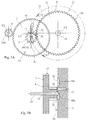
- Fig. 1 includes drawings illustrating a gear device 1 according to the first embodiment of the present invention.
- Fig. 1A is a plan view (a plan view illustrating the gear device 1 while a cover 2 is removed) of the gear device 1.
- Fig. 1B is a vertical cross-sectional view of the gear device 1.
- Fig. 1A transparently illustrates a two-step gear 12 and a second spur gear 11, which are described below in detail, for easily understanding a structure of the gear device 1.
- the gear device 1 illustrated in Fig. 1 includes a first double helical gear 6 secured to a rotation shaft 5 of a motor 4 projecting from a housing 3, a second double helical gear 7 meshed with this first double helical gear 6, a first spur gear 8 integrally formed on a back surface 7a side of the second double helical gear 7 and disposed between the back surface 7a side of the second double helical gear 7 and a surface 3a of the housing 3, and a second spur gear 11 secured to an output shaft 10 so as to be meshed with the first spur gear 8 at the back surface 7a side of the second double helical gear 7.
- the gear device 1 includes a gear train 15 including the first double helical gear 6, the second double helical gear 7, the first spur gear 8, and the second spur gear 11.
- the first double helical gear 6, the two-step gear 12, and the second spur gear 11 are made of synthetic resin materials (polyamide, polyacetal, and the like) or metals (brass, stainless steel, and the like).
- the gear device 1 includes the second double helical gear 7 formed to have a large diameter (a large number of teeth) compared with the first double helical gear 6 and the second spur gear 11 formed to have a large diameter (a large number of teeth) compared with the first spur gear 8, thus decelerating a rotation of the rotation shaft 5 of the motor 4 to transmit the rotation to the output shaft 10.
- the first spur gear 8 has a small diameter compared with the second double helical gear 7, and this prevents visually perceiving a mesh position with the first spur gear 8 from an upper side (a surface side) of the second double helical gear 7.
- the output shaft 10 is coupled to a driven unit (not illustrated) inside the housing 3 so as to transmit the rotation to the driven unit.
- the intermediate shaft 14 has one end side housed in a shaft support hole 17 formed on the housing 3 such that a shaft center C3 is positioned on a straight line 16 connecting a shaft center C1 of the rotation shaft 5 of the motor 4 to a shaft center C2 of the output shaft 10, thus turnably supporting the two-step gear 12. That is, the gear device 1 is configured such that the rotational center (the shaft center C1 of the rotation shaft 5) of the first double helical gear 6, the rotational center (the shaft center C3 of the intermediate shaft 14) of the two-step gear 12, and the rotational center (the shaft center C2 of the output shaft 10) of the second spur gear 11 are positioned on the straight line 16 to transmit the rotation of the rotation shaft 5 of the motor 4 to the output shaft 10.
- the housing 3 includes a pair of meshing guide grooves 18 having the straight line 16 connecting the shaft center C1 of the rotation shaft 5 of the motor 4 to the shaft center C2 of the output shaft 10 as a symmetry axis.
- the meshing guide grooves 18 are elongated holes formed on the surface 3a side (the side of the surface facing the two-step gear 12) of the housing 3 along a pitch circle 20 of the second spur gear 11.
- the meshing guide grooves 18 are formed to have groove centers concentric to the pitch circle 20 of the second spur gear 11, and to be positioned on a virtual circle 21 that passes through the center of the shaft support hole 17.
- the meshing guide grooves 18 are configured to slidingly move (guide) the intermediate shaft 14 to the proximity of the shaft support hole 17.
- the housing 3 has flat surfaces as gear support surfaces 22 at the proximity of an opening edge of the shaft support hole 17. Then, the meshing guide grooves 18 have grooves that gradually decrease in depth toward the gear support surfaces 22 at the proximities of the gear support surfaces 22, and have groove bottoms 18a formed to rise up to the gear support surfaces 22 (the surface 3a of the housing 3).
- the gear support surface 22 is a plane identical to the surface 3a of the housing 3, and turnably supports the two-step gear 12.
- the cover 2 is removably secured to the surface 3a side of the housing 3, forms a space 23 with the housing 3, and turnably houses the gear train 15 including the first double helical gear 6, the two-step gear 12, and the second spur gear 11 in the space 23.
- This cover 2 is secured to the housing 3 such that after the gear train 15 including the first double helical gear 6, the two-step gear 12, and the second spur gear 11 is assembled, an end portion (an upper end portion in Fig. 1 B) of the intermediate shaft 14 is engaged with a first bearing hole 24, and an end portion (an upper end portion in Fig. 1B ) of the output shaft 10 is engaged with a second bearing hole 25.
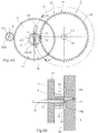
- Fig. 2 includes drawings illustrating a first assembly step of the gear device 1.
- Fig. 2A is a plan view illustrating the gear device 1 while the cover 2 is omitted, and a drawing transparently illustrating the two-step gear 12 and the second spur gear 11.
- Fig. 2B is a cross-sectional view of the gear device 1 taken along a line A1-A1 in Fig. 2A .
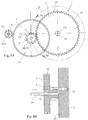
- Fig. 3 includes drawings illustrating a second assembly step of the gear device 1.
- Fig. 3A is a plan view illustrating the gear device 1 while the cover 2 is omitted, and a drawing transparently illustrating the two-step gear 12 and the second spur gear 11.
- Fig. 3B is a cross-sectional view of the gear device 1 taken along a line A2-A2 in Fig. 3A .
- the intermediate shaft 14 in the first assembly step is moved with the two-step gear 12 toward the shaft support hole 17 along the meshing guide groove 18, thus meshing the second double helical gear 7 of the two-step gear 12 with the first double helical gear 6.
- the intermediate shaft 14 and the two-step gear 12 move along the virtual circle 21 concentric to the pitch circle 20 of the second spur gear 11 in a state where the mesh of the first spur gear 8 with the second spur gear 11 is maintained.
- the intermediate shaft 14 is positioned within the meshing guide groove 18, and has not reached the gear support surface 22 at the proximity of the opening edge of the shaft support hole 17.
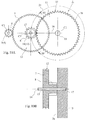
- Fig. 4 includes drawings illustrating a third assembly step of the gear device 1.
- Fig. 4A is a plan view illustrating the gear device 1 while the cover 2 is omitted, and a drawing transparently illustrating the two-step gear 12 and the second spur gear 11.
- Fig. 4B is a cross-sectional view of the gear device 1 taken along a line A3-A3 in Fig. 4A .
- the intermediate shaft 14 in the second assembly step is further moved with the two-step gear 12 toward the shaft support hole 17, and the intermediate shaft 14 is positioned at the proximity of the shaft support hole 17 on the gear support surface 22.
- the two-step gear 12 advances the mesh of the second double helical gear 7 with the first double helical gear 6 while maintaining the mesh of the first spur gear 8 with the second spur gear 11.
- Fig. 5 includes drawings illustrating a fourth assembly step of the gear device 1.
- Fig. 5A is a plan view illustrating the gear device 1 while the cover 2 is omitted, and a drawing transparently illustrating the two-step gear 12 and the second spur gear 11.
- Fig. 5B is a cross-sectional view of the gear device 1 taken along a line A4-A4 in Fig. 5A .
- the intermediate shaft 14 in the third assembly step is moved with the two-step gear 12 to above the shaft support hole 17, and the intermediate shaft 14 is dropped into the shaft support hole 17.
- the first spur gear 8 of the two-step gear 12 is meshed with the second spur gear 11
- the second double helical gear 7 of the two-step gear 12 is meshed with the first double helical gear 6, thus the rotational center (the shaft center C2 of the intermediate shaft 14) of the two-step gear 12 moves along the virtual circle 21.
- the first double helical gear 6, the two-step gear 12 (the second double helical gear 7, the first spur gear 8), and the second spur gear 11 are meshed at a desired mesh position (a mesh position where the rotational center of the first double helical gear 6, the rotational center of the two-step gear 12, and the rotational center of the second spur gear 11 are positioned on the straight line 16), thus the rotation of the rotation shaft 5 of the motor 4 is smoothly transmitted to the output shaft 10 via the first double helical gear 6, the two-step gear 12, and the second spur gear 11.
- the gear device 1 ensures easy assembling of the first double helical gear 6 secured to the rotation shaft 5 of the motor 4 with the second double helical gear 7, which meshes with this first double helical gear 6, of the two-step gear 12, and easy assembling of the first spur gear 8 of the two-step gear 12 with the second spur gear 11 that meshes with this first spur gear 8.
- the pair of the meshing guide grooves 18 having the straight line 16 connecting the shaft center C1 of the rotation shaft 5 of the motor 4 to the shaft center C2 of the output shaft 10 as the symmetry axis are formed on the housing 3. Then, the meshing guide groove 18 that facilitates a work by an assembly worker can be selected to use, thus improving the work efficiency of the assembly.
- the method for assembling the gear device 1 ensures easy assembling of the first double helical gear 6 secured to the rotation shaft 5 of the motor 4 with the second double helical gear 7, which meshes with this first double helical gear 6, of the two-step gear 12, and easy assembling of the first spur gear 8 of the two-step gear 12 with the second spur gear 11 that meshes with this first spur gear 8.
- Fig. 6 includes drawings illustrating a gear device 1 according to a second embodiment of the present invention.
- the gear device 1 illustrated in Fig. 6 has a configuration common to that of the gear device 1 according to the first embodiment excluding a point that the meshing guide groove 18 is not formed. Then, identical reference numerals are attached to configuration parts identical to those of the gear device 1 according to the first embodiment, and therefore the following omits the overlapping explanation.
- Fig. 6A is a plan view (a plan view illustrating the gear device 1 while a cover 2 is removed) of the gear device 1.
- Fig. 6B is a vertical cross-sectional view of the gear device 1. In this embodiment, Fig. 6A transparently illustrates a two-step gear 12 and a second spur gear 11 for easily understanding a structure of the gear device 1.
- Fig. 7 includes drawings illustrating a first assembly step of the gear device 1 according to the embodiment.
- Fig. 7A is a plan view illustrating the gear device 1 while the cover 2 is omitted, and a drawing transparently illustrating the two-step gear 12 and the second spur gear 11.
- Fig. 7B is a cross-sectional view of the gear device 1 taken along a line A5-A5 in Fig. 7A .
- the first spur gear 8 of the two-step gear 12 is meshed with the second spur gear 11 first.
- the second double helical gear 7 of the two-step gear 12 has not meshed with the first double helical gear 6.
- the intermediate shaft 14 is relatively rotatably and slidably movably fitted to the shaft hole 13 of the two-step gear 12.
- Fig. 8 includes drawings illustrating a second assembly step of the gear device 1 according to the embodiment.
- Fig. 8A is a plan view illustrating the gear device 1 while the cover 2 is omitted, and a drawing transparently illustrating the two-step gear 12 and the second spur gear 11.
- Fig. 8B is a cross-sectional view of the gear device 1 taken along a line A6-A6 in Fig. 8A .
- Fig. 9 includes drawings illustrating a third assembly step of the gear device 1 according to the embodiment.
- Fig. 9A is a plan view illustrating the gear device 1 while the cover 2 is omitted, and a drawing transparently illustrating the two-step gear 12 and the second spur gear 11.
- Fig. 9B is a cross-sectional view of the gear device 1 taken along a line A7-A7 in Fig. 9A .
- the two-step gear 12 and the intermediate shaft 14 in the second assembly step are further moved in the direction along the pitch circle 20 of the second spur gear 11 and the direction toward the shaft support hole 17, and the mesh of the second double helical gear 7 with the first double helical gear 6 is advanced while the mesh of the first spur gear 8 with the second spur gear 11 is maintained, thus positioning the intermediate shaft 14 at the proximity of the shaft support hole 17.
- Fig. 10 includes drawings illustrating a fourth assembly step of the gear device 1 according to the embodiment.
- Fig. 10A is a plan view illustrating the gear device 1 while the cover 2 is omitted, and a drawing transparently illustrating the two-step gear 12 and the second spur gear 11.
- Fig. 10B is a cross-sectional view of the gear device 1 taken along a line A8-A8 in Fig. 10A .
- the two-step gear 12 and the intermediate shaft 14 in the third assembly step are moved in the direction along the pitch circle 20 of the second spur gear 11 and the direction toward the shaft support hole 17, thus the intermediate shaft 14 is freely dropped into the shaft support hole 17.
- the first spur gear 8 of the two-step gear 12 is meshed with the second spur gear 11
- the second double helical gear 7 of the two-step gear 12 is meshed with the first double helical gear 6, thus the rotational center (the shaft center C3 of the intermediate shaft 14) of the two-step gear 12 moves along the virtual circle 21 concentric to the pitch circle 20 of the second spur gear 11.
- the first double helical gear 6, the two-step gear 12 (the second double helical gear 7, the first spur gear 8), and the second spur gear 11 are meshed at a desired mesh position (a mesh position where the rotational center of the first double helical gear 6, the rotational center of the two-step gear 12, and the rotational center of the second spur gear 11 are positioned on the straight line 16), thus the rotation of the rotation shaft 5 of the motor 4 is smoothly transmitted to the output shaft 10 via the first double helical gear 6, the two-step gear 12, and the second spur gear 11.
- simply meshing the first spur gear 8 of the two-step gear 12 with the second spur gear 11 and moving the two-step gear 12 and the intermediate shaft 14 in the direction along the pitch circle 20 of the second spur gear 11 and the direction toward the shaft support hole 17 while maintaining the meshing state of the first spur gear 8 with the second spur gear 11 ensure meshing the second double helical gear 7 of the two-step gear 12 with the first double helical gear 6 and smoothly moving the intermediate shaft 14 of the two-step gear 12 to the shaft support hole 17.
- the gear device 1 ensures easy assembling of the first double helical gear 6 secured to the rotation shaft 5 of the motor 4 with the second double helical gear 7, which meshes with this first double helical gear 6, of the two-step gear 12, and easy assembling of the first spur gear 8 of the two-step gear 12 with the second spur gear 11 that meshes with this first spur gear 8.
- the gear device according to the present invention may have a combination of a first helical gear (8) and a second helical gear (11) instead of the first spur gear 8 and the second spur gear 11 of the gear device 1 according to the above-described first and second embodiment.
- a method for assembling the gear device according to the third embodiment of the present invention is similar to the method for assembling the gear device 1 according to the above-described first and second embodiment. Accordingly, the gear device according to the embodiment can provide the effect similar to the effect of the gear device 1 according to the above-described first embodiment.
- the method for assembling the gear device according to the embodiment can provide the effect similar to the effect of the method for assembling the gear device 1 according to the above-described first and second embodiment.
Landscapes
- Engineering & Computer Science (AREA)
- General Engineering & Computer Science (AREA)
- Mechanical Engineering (AREA)
- Gear Transmission (AREA)
- General Details Of Gearings (AREA)
- Gears, Cams (AREA)
Abstract
Description
- The present invention relates to a gear device constituting a power transmission mechanism, and a method for assembling the gear device.
- While a conventional gear device constituting a power transmission mechanism is configured such that helical gears are mutually meshed to transmit rotations so as to reduce operating noise in the rotation transmission, double helical gears are used instead of the helical gears when a negative effect of a thrust force caused by the mesh of the helical gears is considerable (see Patent Document 1).
-
Fig. 11 includes drawings illustrating agear device 100 where double helical gears are used instead of helical gears. Thegear device 100 illustrated inFig. 11 includes agear train 101 that includes a first doublehelical gear 104 secured to arotation shaft 103 of amotor 102, a second doublehelical gear 105 meshed with this first doublehelical gear 104, afirst spur gear 107 integrally formed on aback surface 105a side (a side of a surface facing a housing 106) of this second doublehelical gear 105, and asecond spur gear 108 meshed with thisfirst spur gear 107 at theback surface 105a side of the second doublehelical gear 105. Thisgear device 100 illustrated inFig. 11 is configured such that the second doublehelical gear 105 has a large diameter (a large number of teeth) compared with the first doublehelical gear 104 and thesecond spur gear 108 has a large diameter (a large number of teeth) compared with thefirst spur gear 107 so as to transmit the rotation of themotor 102 to the first doublehelical gear 104, the second doublehelical gear 105, thefirst spur gear 107, and thesecond spur gear 108 in this order to decelerate the rotation, thus transmitting the decelerated rotation of themotor 102 from anoutput shaft 110, which integrally turns with thesecond spur gear 108, to a driven unit (not illustrated). - Patent Document 1:
JP-A-8-284677 - The
gear device 100 illustrated inFig. 11 needs to be assembled such that a two-step gear 111, which includes the second doublehelical gear 105 and thefirst spur gear 107, is meshed with the first doublehelical gear 104 secured to therotation shaft 103 of themotor 102 and thesecond spur gear 108 secured to theoutput shaft 110. In thisgear device 100 illustrated inFig. 11 , the two-step gear 111 needs to mesh the second doublehelical gear 105 with the first doublehelical gear 104 while meshing thefirst spur gear 107 with thesecond spur gear 108. To ensure such assembling of thegear device 100, as disclosed inPatent Document 1, it is conceivable that the first doublehelical gear 104 is divided into a firsthelical gear 104a and a secondhelical gear 104b along a tooth width direction, the firsthelical gear 104a is meshed with the second doublehelical gear 105, subsequently, the secondhelical gear 104b is meshed with the second doublehelical gear 105, and the secondhelical gear 104b is secured to the firsthelical gear 104a with a plurality of bolts to be integrated (seeFig. 12 ). However, since thegear device 100 illustrated inFig. 11 is a gear device to decelerate the rotation of themotor 102 and the first doublehelical gear 104 has the small diameter, there is no space for disposing the plurality of securing bolts, and there has been a problem that the technique disclosed inPatent Document 1 is not applicable to thegear device 100. - Therefore, the applicant of this application has developed a gear device that ensures easily assembling a gear train in which double helical gears need to be mutually meshed, and a method for assembling the gear device.
- The present invention relates to a
gear device 1 that includes: - (A). a first double
helical gear 6 secured to arotation shaft 5 of amotor 4, therotation shaft 5 projecting from ahousing 3; - (B). a two-
step gear 12 that includes a second doublehelical gear 7 and afirst spur gear 8, the second doublehelical gear 7 meshing with the first doublehelical gear 6, thefirst spur gear 8 being integrally formed on aback surface 7a side of the second doublehelical gear 7, thefirst spur gear 8 being disposed between theback surface 7a side of the second doublehelical gear 7 and asurface 3a of thehousing 3; - (C). a
second spur gear 11 secured to anoutput shaft 10 such that thesecond spur gear 11 meshes with thefirst spur gear 8 at theback surface 7a side of the second doublehelical gear 7; and - (D). an
intermediate shaft 14 fitted to ashaft hole 13 of the two-step gear 12, theintermediate shaft 14 relatively rotatably and slidably movably supporting the two-step gear 12. - Then, the
housing 3 has ashaft support hole 17 and ameshing guide groove 18. The shaft supporthole 17 houses one end side of theintermediate shaft 14 fitted to theshaft hole 13 of the two-step gear 12 at a desired mesh position of the first doublehelical gear 6 with the second doublehelical gear 7. Themeshing guide groove 18 meshes the second doublehelical gear 7 with the first doublehelical gear 6 by guiding theintermediate shaft 14 fitted to theshaft hole 13 of the two-step gear 12 along apitch circle 20 of thesecond spur gear 11 to a proximity of theshaft support hole 17 while maintaining a state where thefirst spur gear 8 meshes with thesecond spur gear 11. Themeshing guide groove 18 is formed to have a groove depth that smoothly and gradually decreases to thesurface 3a of thehousing 3 at the proximity of theshaft support hole 17. - The present invention relates to a
gear device 1 that includes: - (A). a first double
helical gear 6 secured to arotation shaft 5 of amotor 4, the rotation shaft projecting from ahousing 3; - (B). a two-
step gear 12 that includes a second doublehelical gear 7 and a first helical gear (8), the second doublehelical gear 7 meshing with the first doublehelical gear 6, the first helical gear (8) being integrally formed on aback surface 7a side of the second doublehelical gear 7, the first helical gear (8) being disposed between theback surface 7a side of the second doublehelical gear 7 and asurface 3a of thehousing 3; - (C). a second helical gear (11) secured to an
output shaft 10 such that the second helical gear (11) meshes with the first helical gear (8) at theback surface 7a side of the second doublehelical gear 7; and - (D). an
intermediate shaft 14 fitted to ashaft hole 13 of the two-step gear 12, theintermediate shaft 14 relatively rotatably and slidably movably supporting the two-step gear 12. - Then, the
housing 3 has ashaft support hole 17 and ameshing guide groove 18. The shaft supporthole 17 houses one end side of theintermediate shaft 14 fitted to theshaft hole 13 of the two-step gear 12 at a desired mesh position of the first doublehelical gear 6 with the second doublehelical gear 7. Themeshing guide groove 18 meshes the second doublehelical gear 7 with the first doublehelical gear 6 by guiding theintermediate shaft 14 fitted to theshaft hole 13 of the two-step gear 12 along apitch circle 20 of the second helical gear (11) to a proximity of theshaft support hole 17 while maintaining a state where the first helical gear (8) meshes with the second helical gear (11). Themeshing guide groove 18 is formed to have a groove depth that smoothly and gradually decreases to thesurface 3a of thehousing 3 at the proximity of theshaft support hole 17. - With the gear device of the present invention, simply meshing the first spur gear of the two-step gear with the second spur gear and engaging the intermediate shaft of the two-step gear with the meshing guide groove and moving the intermediate shaft along the meshing guide groove ensure meshing the second double helical gear of the two-step gear with the first double helical gear and smoothly moving the intermediate shaft of the two-step gear to the shaft support hole. As a result, the gear device according to the present invention ensures easy assembling of the first double helical gear secured to the rotation shaft of the motor with the second double helical gear, which meshes with this first double helical gear, of the two-step gear, and easy assembling of the first spur gear of the two-step gear with the second spur gear that meshes with this first spur gear.
- With the gear device of the present invention, simply meshing the first helical gear of the two-step gear with the second helical gear and engaging the intermediate shaft of the two-step gear with the meshing guide groove and moving the intermediate shaft along the meshing guide groove ensure meshing the second double helical gear of the two-step gear with the first double helical gear and smoothly moving the intermediate shaft of the two-step gear to the shaft support hole. As a result, the gear device according to the present invention ensures easy assembling of the first double helical gear secured to the rotation shaft of the motor with the second double helical gear, which meshes with this first double helical gear, of the two-step gear, and easy assembling of the first helical gear of the two-step gear with the second helical gear that meshes with this first helical gear.
-
-
Fig. 1 includes drawings illustrating a gear device according to a first embodiment of the present invention,Fig. 1A is a plan view (a plan view illustrating the gear device while a cover is removed, and a drawing transparently illustrating a two-step gear and a second spur gear) of the gear device, andFig. 1B is a vertical cross-sectional view of the gear device. -
Fig. 2 includes drawings illustrating a first assembly step of the gear device according to the first embodiment of the present invention,Fig. 2A is a plan view (a drawing transparently illustrating the two-step gear and the second spur gear) of the gear device while the cover is omitted, andFig. 2B is a cross-sectional view of the gear device taken along a line A1-A1 inFig. 2A . -
Fig. 3 includes drawings illustrating a second assembly step of the gear device according to the first embodiment of the present invention,Fig. 3A is a plan view (a drawing transparently illustrating the two-step gear and the second spur gear) of the gear device while the cover is omitted, andFig. 3B is a cross-sectional view of the gear device taken along a line A2-A2 inFig. 3A . -
Fig. 4 includes drawings illustrating a third assembly step of the gear device according to the first embodiment of the present invention,Fig. 4A is a plan view (a drawing transparently illustrating the two-step gear and the second spur gear) of the gear device while the cover is omitted, andFig. 4B is a cross-sectional view of the gear device taken along a line A3-A3 inFig. 4A . -
Fig. 5 includes drawings illustrating a fourth assembly step of the gear device according to the first embodiment of the present invention,Fig. 5A is a plan view (a drawing transparently illustrating the two-step gear and the second spur gear) of the gear device while the cover is omitted, andFig. 5B is a cross-sectional view of the gear device taken along a line A4-A4 inFig. 5A . -
Fig. 6 includes drawings illustrating a gear device according to a second embodiment of the present invention,Fig. 6A is a plan view (a plan view illustrating the gear device while a cover is removed, and a drawing transparently illustrating a two-step gear and a second spur gear) of the gear device, andFig. 6B is a vertical cross-sectional view of the gear device. -
Fig. 7 includes drawings illustrating a first assembly step of the gear device according to the second embodiment of the present invention,Fig. 7A is a plan view (a drawing transparently illustrating the two-step gear and the second spur gear) of the gear device while the cover is omitted, andFig. 7B is a cross-sectional view of the gear device taken along a line A5-A5 inFig. 7A . -
Fig. 8 includes drawings illustrating a second assembly step of the gear device according to the second embodiment of the present invention,Fig. 8A is a plan view (a drawing transparently illustrating the two-step gear and the second spur gear) of the gear device while the cover is omitted, andFig. 8B is a cross-sectional view of the gear device taken along a line A6-A6 inFig. 8A . -
Fig. 9 includes drawings illustrating a third assembly step of the gear device according to the second embodiment of the present invention,Fig. 9A is a plan view (a drawing transparently illustrating the two-step gear and the second spur gear) of the gear device while the cover is omitted, andFig. 9B is a cross-sectional view of the gear device taken along a line A7-A7 inFig. 9A . -
Fig. 10 includes drawings illustrating a fourth assembly step of the gear device according to the second embodiment of the present invention,Fig. 10A is a plan view (a drawing transparently illustrating the two-step gear and the second spur gear) of the gear device while the cover is omitted, andFig. 10B is a cross-sectional view of the gear device taken along a line A8-A8 inFig. 10A . -
Fig. 11 includes drawings illustrating a gear device as a development target,Fig. 11A is a plan view (a plan view illustrating the gear device while a cover is removed) of the gear device, andFig. 11B is a vertical cross-sectional view of the gear device. -
Fig. 12A is a drawing illustrating a first assembled state of the gear device illustrated inFig. 11 , andFig. 12B is a drawing illustrating a second assembled state of the gear device illustrated inFig. 11 . - The following describes a first embodiment of the present invention in detail based on the drawings.
-
Fig. 1 includes drawings illustrating agear device 1 according to the first embodiment of the present invention.Fig. 1A is a plan view (a plan view illustrating thegear device 1 while acover 2 is removed) of thegear device 1.Fig. 1B is a vertical cross-sectional view of thegear device 1. In this embodiment,Fig. 1A transparently illustrates a two-step gear 12 and asecond spur gear 11, which are described below in detail, for easily understanding a structure of thegear device 1. - The
gear device 1 illustrated inFig. 1 includes a first doublehelical gear 6 secured to arotation shaft 5 of amotor 4 projecting from ahousing 3, a second doublehelical gear 7 meshed with this first doublehelical gear 6, afirst spur gear 8 integrally formed on aback surface 7a side of the second doublehelical gear 7 and disposed between theback surface 7a side of the second doublehelical gear 7 and asurface 3a of thehousing 3, and asecond spur gear 11 secured to anoutput shaft 10 so as to be meshed with thefirst spur gear 8 at theback surface 7a side of the second doublehelical gear 7. Then, the second doublehelical gear 7 and thefirst spur gear 8 constitute the two-step gear 12 configured such that ashaft hole 13 is disposed on a position of the rotational center, and anintermediate shaft 14 is relatively turnably and slidably movably fitted to theshaft hole 13. Thus, thegear device 1 includes agear train 15 including the first doublehelical gear 6, the second doublehelical gear 7, thefirst spur gear 8, and thesecond spur gear 11. The first doublehelical gear 6, the two-step gear 12, and thesecond spur gear 11 are made of synthetic resin materials (polyamide, polyacetal, and the like) or metals (brass, stainless steel, and the like). - As illustrated in
Fig. 1 , thegear device 1 includes the second doublehelical gear 7 formed to have a large diameter (a large number of teeth) compared with the first doublehelical gear 6 and thesecond spur gear 11 formed to have a large diameter (a large number of teeth) compared with thefirst spur gear 8, thus decelerating a rotation of therotation shaft 5 of themotor 4 to transmit the rotation to theoutput shaft 10. Thefirst spur gear 8 has a small diameter compared with the second doublehelical gear 7, and this prevents visually perceiving a mesh position with thefirst spur gear 8 from an upper side (a surface side) of the second doublehelical gear 7. Theoutput shaft 10 is coupled to a driven unit (not illustrated) inside thehousing 3 so as to transmit the rotation to the driven unit. - The
intermediate shaft 14 has one end side housed in ashaft support hole 17 formed on thehousing 3 such that a shaft center C3 is positioned on astraight line 16 connecting a shaft center C1 of therotation shaft 5 of themotor 4 to a shaft center C2 of theoutput shaft 10, thus turnably supporting the two-step gear 12. That is, thegear device 1 is configured such that the rotational center (the shaft center C1 of the rotation shaft 5) of the first doublehelical gear 6, the rotational center (the shaft center C3 of the intermediate shaft 14) of the two-step gear 12, and the rotational center (the shaft center C2 of the output shaft 10) of thesecond spur gear 11 are positioned on thestraight line 16 to transmit the rotation of therotation shaft 5 of themotor 4 to theoutput shaft 10. - The
housing 3 includes a pair of meshingguide grooves 18 having thestraight line 16 connecting the shaft center C1 of therotation shaft 5 of themotor 4 to the shaft center C2 of theoutput shaft 10 as a symmetry axis. The meshingguide grooves 18 are elongated holes formed on thesurface 3a side (the side of the surface facing the two-step gear 12) of thehousing 3 along apitch circle 20 of thesecond spur gear 11. The meshingguide grooves 18 are formed to have groove centers concentric to thepitch circle 20 of thesecond spur gear 11, and to be positioned on avirtual circle 21 that passes through the center of theshaft support hole 17. The meshingguide grooves 18 are configured to slidingly move (guide) theintermediate shaft 14 to the proximity of theshaft support hole 17. Thehousing 3 has flat surfaces as gear support surfaces 22 at the proximity of an opening edge of theshaft support hole 17. Then, the meshingguide grooves 18 have grooves that gradually decrease in depth toward the gear support surfaces 22 at the proximities of the gear support surfaces 22, and havegroove bottoms 18a formed to rise up to the gear support surfaces 22 (thesurface 3a of the housing 3). Thegear support surface 22 is a plane identical to thesurface 3a of thehousing 3, and turnably supports the two-step gear 12. - The
cover 2 is removably secured to thesurface 3a side of thehousing 3, forms aspace 23 with thehousing 3, and turnably houses thegear train 15 including the first doublehelical gear 6, the two-step gear 12, and thesecond spur gear 11 in thespace 23. Thiscover 2 is secured to thehousing 3 such that after thegear train 15 including the first doublehelical gear 6, the two-step gear 12, and thesecond spur gear 11 is assembled, an end portion (an upper end portion inFig. 1 B) of theintermediate shaft 14 is engaged with afirst bearing hole 24, and an end portion (an upper end portion inFig. 1B ) of theoutput shaft 10 is engaged with asecond bearing hole 25. -
Fig. 2 includes drawings illustrating a first assembly step of thegear device 1.Fig. 2A is a plan view illustrating thegear device 1 while thecover 2 is omitted, and a drawing transparently illustrating the two-step gear 12 and thesecond spur gear 11.Fig. 2B is a cross-sectional view of thegear device 1 taken along a line A1-A1 inFig. 2A . - In this first assembly step of the
gear device 1 illustrated inFig. 2 , among the first doublehelical gear 6 secured to therotation shaft 5 of themotor 4 and thesecond spur gear 11 secured to theoutput shaft 10, thefirst spur gear 8 of the two-step gear 12 is meshed with thesecond spur gear 11 first, and a distal end side (one end side), which is fitted to theshaft hole 13 of the two-step gear 12, of theintermediate shaft 14 is engaged with the meshingguide groove 18. -
Fig. 3 includes drawings illustrating a second assembly step of thegear device 1.Fig. 3A is a plan view illustrating thegear device 1 while thecover 2 is omitted, and a drawing transparently illustrating the two-step gear 12 and thesecond spur gear 11.Fig. 3B is a cross-sectional view of thegear device 1 taken along a line A2-A2 inFig. 3A . - In this second assembly step of the
gear device 1 illustrated inFig. 3 , theintermediate shaft 14 in the first assembly step is moved with the two-step gear 12 toward theshaft support hole 17 along the meshingguide groove 18, thus meshing the second doublehelical gear 7 of the two-step gear 12 with the first doublehelical gear 6. At this time, theintermediate shaft 14 and the two-step gear 12 move along thevirtual circle 21 concentric to thepitch circle 20 of thesecond spur gear 11 in a state where the mesh of thefirst spur gear 8 with thesecond spur gear 11 is maintained. In this second assembly step of thegear device 1 illustrated inFig. 3 , theintermediate shaft 14 is positioned within the meshingguide groove 18, and has not reached thegear support surface 22 at the proximity of the opening edge of theshaft support hole 17. -
Fig. 4 includes drawings illustrating a third assembly step of thegear device 1.Fig. 4A is a plan view illustrating thegear device 1 while thecover 2 is omitted, and a drawing transparently illustrating the two-step gear 12 and thesecond spur gear 11.Fig. 4B is a cross-sectional view of thegear device 1 taken along a line A3-A3 inFig. 4A . - In this third assembly step of the
gear device 1 illustrated inFig. 4 , theintermediate shaft 14 in the second assembly step is further moved with the two-step gear 12 toward theshaft support hole 17, and theintermediate shaft 14 is positioned at the proximity of theshaft support hole 17 on thegear support surface 22. At this time, the two-step gear 12 advances the mesh of the second doublehelical gear 7 with the first doublehelical gear 6 while maintaining the mesh of thefirst spur gear 8 with thesecond spur gear 11. -
Fig. 5 includes drawings illustrating a fourth assembly step of thegear device 1.Fig. 5A is a plan view illustrating thegear device 1 while thecover 2 is omitted, and a drawing transparently illustrating the two-step gear 12 and thesecond spur gear 11.Fig. 5B is a cross-sectional view of thegear device 1 taken along a line A4-A4 inFig. 5A . - In this fourth assembly step of the
gear device 1 illustrated inFig. 5 , theintermediate shaft 14 in the third assembly step is moved with the two-step gear 12 to above theshaft support hole 17, and theintermediate shaft 14 is dropped into theshaft support hole 17. At this time, thefirst spur gear 8 of the two-step gear 12 is meshed with thesecond spur gear 11, and the second doublehelical gear 7 of the two-step gear 12 is meshed with the first doublehelical gear 6, thus the rotational center (the shaft center C2 of the intermediate shaft 14) of the two-step gear 12 moves along thevirtual circle 21. Accordingly, the first doublehelical gear 6, the two-step gear 12 (the second doublehelical gear 7, the first spur gear 8), and thesecond spur gear 11 are meshed at a desired mesh position (a mesh position where the rotational center of the first doublehelical gear 6, the rotational center of the two-step gear 12, and the rotational center of thesecond spur gear 11 are positioned on the straight line 16), thus the rotation of therotation shaft 5 of themotor 4 is smoothly transmitted to theoutput shaft 10 via the first doublehelical gear 6, the two-step gear 12, and thesecond spur gear 11. - As described above, with the
gear device 1 of this embodiment, simply meshing thefirst spur gear 8 of the two-step gear 12 with thesecond spur gear 11 and engaging theintermediate shaft 14 of the two-step gear 12 with the meshingguide groove 18 and moving theintermediate shaft 14 along the meshingguide groove 18 ensure meshing the second doublehelical gear 7 of the two-step gear 12 with the first doublehelical gear 6 and smoothly moving theintermediate shaft 14 of the two-step gear 12 to theshaft support hole 17. As a result, thegear device 1 according to the embodiment ensures easy assembling of the first doublehelical gear 6 secured to therotation shaft 5 of themotor 4 with the second doublehelical gear 7, which meshes with this first doublehelical gear 6, of the two-step gear 12, and easy assembling of thefirst spur gear 8 of the two-step gear 12 with thesecond spur gear 11 that meshes with thisfirst spur gear 8. - With the
gear device 1 of this embodiment, simply engaging theintermediate shaft 14 with the meshingguide groove 18 determines an interaxial distance between thefirst spur gear 8 and thesecond spur gear 11, thus ensuring easy meshing of thefirst spur gear 8 with thesecond spur gear 11 even in a state where the mesh position of thefirst spur gear 8 with thesecond spur gear 11 cannot be visually perceived from the upper side of the second doublehelical gear 7. - According to the
gear device 1 of this embodiment, the pair of the meshingguide grooves 18 having thestraight line 16 connecting the shaft center C1 of therotation shaft 5 of themotor 4 to the shaft center C2 of theoutput shaft 10 as the symmetry axis are formed on thehousing 3. Then, the meshingguide groove 18 that facilitates a work by an assembly worker can be selected to use, thus improving the work efficiency of the assembly. - With the method for assembling the
gear device 1 according to the embodiment, simply meshing thefirst spur gear 8 of the two-step gear 12 with thesecond spur gear 11 and engaging theintermediate shaft 14 of the two-step gear 12 with the meshingguide groove 18 and moving theintermediate shaft 14 along the meshingguide groove 18 ensure meshing the second doublehelical gear 7 of the two-step gear 12 with the first doublehelical gear 6 and smoothly moving theintermediate shaft 14 of the two-step gear 12 to theshaft support hole 17. As a result, the method for assembling thegear device 1 according to the embodiment ensures easy assembling of the first doublehelical gear 6 secured to therotation shaft 5 of themotor 4 with the second doublehelical gear 7, which meshes with this first doublehelical gear 6, of the two-step gear 12, and easy assembling of thefirst spur gear 8 of the two-step gear 12 with thesecond spur gear 11 that meshes with thisfirst spur gear 8. -
Fig. 6 includes drawings illustrating agear device 1 according to a second embodiment of the present invention. Thegear device 1 illustrated inFig. 6 has a configuration common to that of thegear device 1 according to the first embodiment excluding a point that the meshingguide groove 18 is not formed. Then, identical reference numerals are attached to configuration parts identical to those of thegear device 1 according to the first embodiment, and therefore the following omits the overlapping explanation.Fig. 6A is a plan view (a plan view illustrating thegear device 1 while acover 2 is removed) of thegear device 1.Fig. 6B is a vertical cross-sectional view of thegear device 1. In this embodiment,Fig. 6A transparently illustrates a two-step gear 12 and asecond spur gear 11 for easily understanding a structure of thegear device 1. -
Fig. 7 includes drawings illustrating a first assembly step of thegear device 1 according to the embodiment.Fig. 7A is a plan view illustrating thegear device 1 while thecover 2 is omitted, and a drawing transparently illustrating the two-step gear 12 and thesecond spur gear 11.Fig. 7B is a cross-sectional view of thegear device 1 taken along a line A5-A5 inFig. 7A . - In this first assembly step of the
gear device 1 illustrated inFig. 7 , among the first doublehelical gear 6 secured to therotation shaft 5 of themotor 4 and thesecond spur gear 11 secured to theoutput shaft 10, thefirst spur gear 8 of the two-step gear 12 is meshed with thesecond spur gear 11 first. At this time, the second doublehelical gear 7 of the two-step gear 12 has not meshed with the first doublehelical gear 6. Theintermediate shaft 14 is relatively rotatably and slidably movably fitted to theshaft hole 13 of the two-step gear 12. -
Fig. 8 includes drawings illustrating a second assembly step of thegear device 1 according to the embodiment.Fig. 8A is a plan view illustrating thegear device 1 while thecover 2 is omitted, and a drawing transparently illustrating the two-step gear 12 and thesecond spur gear 11.Fig. 8B is a cross-sectional view of thegear device 1 taken along a line A6-A6 inFig. 8A . - In this second assembly step of the
gear device 1 illustrated inFig. 8 , the two-step gear 12 and theintermediate shaft 14 in the first assembly step are moved in a direction along thepitch circle 20 of thesecond spur gear 11 and a direction toward theshaft support hole 17 while the meshing state of thefirst spur gear 8 with thesecond spur gear 11 is maintained, thus meshing the second doublehelical gear 7 of the two-step gear 12 with the first doublehelical gear 6. -
Fig. 9 includes drawings illustrating a third assembly step of thegear device 1 according to the embodiment.Fig. 9A is a plan view illustrating thegear device 1 while thecover 2 is omitted, and a drawing transparently illustrating the two-step gear 12 and thesecond spur gear 11.Fig. 9B is a cross-sectional view of thegear device 1 taken along a line A7-A7 inFig. 9A . - In this third assembly step of the
gear device 1 illustrated inFig. 9 , the two-step gear 12 and theintermediate shaft 14 in the second assembly step are further moved in the direction along thepitch circle 20 of thesecond spur gear 11 and the direction toward theshaft support hole 17, and the mesh of the second doublehelical gear 7 with the first doublehelical gear 6 is advanced while the mesh of thefirst spur gear 8 with thesecond spur gear 11 is maintained, thus positioning theintermediate shaft 14 at the proximity of theshaft support hole 17. -
Fig. 10 includes drawings illustrating a fourth assembly step of thegear device 1 according to the embodiment.Fig. 10A is a plan view illustrating thegear device 1 while thecover 2 is omitted, and a drawing transparently illustrating the two-step gear 12 and thesecond spur gear 11.Fig. 10B is a cross-sectional view of thegear device 1 taken along a line A8-A8 inFig. 10A . - In this fourth assembly step of the
gear device 1 illustrated inFig. 10 , the two-step gear 12 and theintermediate shaft 14 in the third assembly step are moved in the direction along thepitch circle 20 of thesecond spur gear 11 and the direction toward theshaft support hole 17, thus theintermediate shaft 14 is freely dropped into theshaft support hole 17. At this time, thefirst spur gear 8 of the two-step gear 12 is meshed with thesecond spur gear 11, the second doublehelical gear 7 of the two-step gear 12 is meshed with the first doublehelical gear 6, thus the rotational center (the shaft center C3 of the intermediate shaft 14) of the two-step gear 12 moves along thevirtual circle 21 concentric to thepitch circle 20 of thesecond spur gear 11. Accordingly, the first doublehelical gear 6, the two-step gear 12 (the second doublehelical gear 7, the first spur gear 8), and thesecond spur gear 11 are meshed at a desired mesh position (a mesh position where the rotational center of the first doublehelical gear 6, the rotational center of the two-step gear 12, and the rotational center of thesecond spur gear 11 are positioned on the straight line 16), thus the rotation of therotation shaft 5 of themotor 4 is smoothly transmitted to theoutput shaft 10 via the first doublehelical gear 6, the two-step gear 12, and thesecond spur gear 11. - As described above, with the method for assembling the
gear device 1 according to the embodiment, simply meshing thefirst spur gear 8 of the two-step gear 12 with thesecond spur gear 11 and moving the two-step gear 12 and theintermediate shaft 14 in the direction along thepitch circle 20 of thesecond spur gear 11 and the direction toward theshaft support hole 17 while maintaining the meshing state of thefirst spur gear 8 with thesecond spur gear 11 ensure meshing the second doublehelical gear 7 of the two-step gear 12 with the first doublehelical gear 6 and smoothly moving theintermediate shaft 14 of the two-step gear 12 to theshaft support hole 17. As a result, thegear device 1 according to the embodiment ensures easy assembling of the first doublehelical gear 6 secured to therotation shaft 5 of themotor 4 with the second doublehelical gear 7, which meshes with this first doublehelical gear 6, of the two-step gear 12, and easy assembling of thefirst spur gear 8 of the two-step gear 12 with thesecond spur gear 11 that meshes with thisfirst spur gear 8. - The gear device according to the present invention may have a combination of a first helical gear (8) and a second helical gear (11) instead of the
first spur gear 8 and thesecond spur gear 11 of thegear device 1 according to the above-described first and second embodiment. Such a method for assembling the gear device according to the third embodiment of the present invention is similar to the method for assembling thegear device 1 according to the above-described first and second embodiment. Accordingly, the gear device according to the embodiment can provide the effect similar to the effect of thegear device 1 according to the above-described first embodiment. The method for assembling the gear device according to the embodiment can provide the effect similar to the effect of the method for assembling thegear device 1 according to the above-described first and second embodiment. -
- 1:
- Gear device
- 3:
- Housing
- 3a:
- Surface
- 4:
- Motor
- 5:
- Rotation shaft
- 6:
- First double helical gear
- 7:
- Second double helical gear
- 7a:
- Back surface
- 8:
- First spur gear
- (8):
- First helical gear
- 10:
- Output shaft
- 11:
- Second spur gear
- (11)
- Second helical gear
- 12:
- Two-step gear
- 13:
- Shaft hole
- 14:
- Intermediate shaft
- 17:
- Shaft support hole
- 18:
- Meshing guide groove
- 20:
- Pitch circle
Claims (9)
- A gear device comprising:a first double helical gear secured to a rotation shaft of a motor, the rotation shaft projecting from a housing;a two-step gear that includes a second double helical gear and a first spur gear, the second double helical gear meshing with the first double helical gear, the first spur gear being integrally formed on a back surface side of the second double helical gear, the first spur gear being disposed between the back surface side of the second double helical gear and a surface of the housing;a second spur gear secured to an output shaft such that the second spur gear meshes with the first spur gear at the back surface side of the second double helical gear; andan intermediate shaft fitted to a shaft hole of the two-step gear, the intermediate shaft relatively rotatably and slidably movably supporting the two-step gear, whereinthe housing includes:a shaft support hole that houses one end side of the intermediate shaft fitted to the shaft hole of the two-step gear at a desired mesh position of the first double helical gear with the second double helical gear; anda meshing guide groove that meshes the second double helical gear with the first double helical gear by guiding the intermediate shaft fitted to the shaft hole of the two-step gear along a pitch circle of the second spur gear to a proximity of the shaft support hole while maintaining a state where the first spur gear meshes with the second spur gear, andthe meshing guide groove is formed to have a groove depth that smoothly and gradually decreases to the surface of the housing at the proximity of the shaft support hole.
- The gear device according to claim 1, wherein
the second double helical gear has a large diameter compared with the first spur gear. - A gear device comprising:a first double helical gear secured to a rotation shaft of a motor, the rotation shaft projecting from a housing;a two-step gear that includes a second double helical gear and a first helical gear, the second double helical gear meshing with the first double helical gear, the first helical gear being integrally formed on a back surface side of the second double helical gear, the first helical gear being disposed between the back surface side of the second double helical gear and a surface of the housing;a second helical gear secured to an output shaft such that the second helical gear meshes with the first spur gear at the back surface side of the second double helical gear; andan intermediate shaft fitted to a shaft hole of the two-step gear, the intermediate shaft relatively rotatably and slidably movably supporting the two-step gear, whereinthe housing includes:a shaft support hole that houses one end side of the intermediate shaft fitted to the shaft hole of the two-step gear at a desired mesh position of the first double helical gear with the second double helical gear; anda meshing guide groove that meshes the second double helical gear with the first double helical gear by guiding the intermediate shaft fitted to the shaft hole of the two-step gear along a pitch circle of the second helical gear to a proximity of the shaft support hole while maintaining a state where the first helical gear meshes with the second helical gear, andthe meshing guide groove is formed to have a groove depth that smoothly and gradually decreases to the surface of the housing at the proximity of the shaft support hole.
- The gear device according to claim 3, wherein
the second double helical gear has a large diameter compared with the first helical gear. - The gear device according to any one of claims 1 to 4, wherein:a shaft center of the rotation shaft, a shaft center of the intermediate shaft, and a shaft center of the output shaft are positioned in an identical straight manner, anda pair of the meshing guide grooves are formed to have a straight line as a symmetry axis, the straight line connecting the shaft center of the rotation shaft to the shaft center of the output shaft.
- A method for assembling a gear device, wherein
the gear device includes:a first double helical gear secured to a rotation shaft of a motor, the rotation shaft projecting from a housing;a two-step gear that includes a second double helical gear and a first spur gear, the second double helical gear meshing with the first double helical gear, the first spur gear being integrally formed on a back surface side of the second double helical gear, the first spur gear being disposed between the back surface side of the second double helical gear and a surface of the housing;a second spur gear secured to an output shaft such that the second spur gear meshes with the first spur gear at the back surface side of the second double helical gear; andan intermediate shaft fitted to a shaft hole of the two-step gear, the intermediate shaft relatively rotatably and slidably movably supporting the two-step gear, whereinthe housing includes:a shaft support hole that houses one end side of the intermediate shaft fitted to the shaft hole of the two-step gear at a desired mesh position of the first double helical gear with the second double helical gear; anda meshing guide groove that meshes the second double helical gear with the first double helical gear by guiding the intermediate shaft fitted to the shaft hole of the two-step gear along a pitch circle of the second spur gear to a proximity of the shaft support hole while maintaining a state where the first spur gear meshes with the second spur gear, whereinthe meshing guide groove is formed to have a groove depth that smoothly and gradually decreases to the surface of the housing at the proximity of the shaft support hole, and wherein
the method for assembling the gear device comprises:meshing the first spur gear with the second spur gear and engaging the one end side of the intermediate shaft with the meshing guide groove;subsequently moving the intermediate shaft with the two-step gear toward the shaft support hole along the meshing guide groove to mesh the second double helical gear of the two-step gear with the first double helical gear;further moving the intermediate shaft with the two-step gear toward the shaft support hole to position the intermediate shaft at the proximity of the shaft support hole for causing the mesh of the second double helical gear with the first double helical gear to advance while maintaining the mesh of the first spur gear with the second spur gear; andsubsequently moving the intermediate shaft with the two-step gear to above the shaft support hole and dropping the intermediate shaft into the shaft support hole. - A method for assembling a gear device, wherein
the gear device includes:a first double helical gear secured to a rotation shaft of a motor, the rotation shaft projecting from a housing;a two-step gear that includes a second double helical gear and a first helical gear, the second double helical gear meshing with the first double helical gear, the first helical gear being integrally formed on a back surface side of the second double helical gear, the first helical gear being disposed between the back surface side of the second double helical gear and a surface of the housing;a second helical gear secured to an output shaft such that the second helical gear meshes with the first helical gear at the back surface side of the second double helical gear; andan intermediate shaft fitted to a shaft hole of the two-step gear, the intermediate shaft relatively rotatably and slidably movably supporting the two-step gear, whereinthe housing includes:a shaft support hole that houses one end side of the intermediate shaft fitted to the shaft hole of the two-step gear at a desired mesh position of the first double helical gear with the second double helical gear; anda meshing guide groove that meshes the second double helical gear with the first double helical gear by guiding the intermediate shaft fitted to the shaft hole of the two-step gear along a pitch circle of the second helical gear to a proximity of the shaft support hole while maintaining a state where the first helical gear meshes with the second helical gear, whereinthe meshing guide groove is formed to have a groove depth that smoothly and gradually decreases to the surface of the housing at the proximity of the shaft support hole, and wherein
the method for assembling the gear device comprises:meshing the first helical gear with the second helical gear and engaging the one end side of the intermediate shaft with the meshing guide groove;subsequently moving the intermediate shaft with the two-step gear toward the shaft support hole along the meshing guide groove to mesh the second double helical gear of the two-step gear with the first double helical gear;further moving the intermediate shaft with the two-step gear toward the shaft support hole to position the intermediate shaft at the proximity of the shaft support hole for causing the mesh of the second double helical gear with the first double helical gear to advance while maintaining the mesh of the first helical gear with the second helical gear; andsubsequently moving the intermediate shaft with the two-step gear to above the shaft support hole and dropping the intermediate shaft into the shaft support hole. - A method for assembling a gear device, wherein
the gear device includes:a first double helical gear secured to a rotation shaft of a motor, the rotation shaft projecting from the housing;a two-step gear that includes a second double helical gear and a first spur gear, the second double helical gear meshing with the first double helical gear, the first spur gear being integrally formed on a back surface side of the second double helical gear, the first spur gear being disposed between the back surface side of the second double helical gear and a surface of the housing;a second spur gear secured to an output shaft such that the second spur gear meshes with the first spur gear at the back surface side of the second double helical gear; andan intermediate shaft fitted to a shaft hole of the two-step gear, the intermediate shaft relatively rotatably and slidably movably supporting the two-step gear, whereinthe housing includes a shaft support hole that houses one end side of the intermediate shaft fitted to the shaft hole of the two-step gear at a desired mesh position of the first double helical gear with the second double helical gear, and wherein
the method for assembling the gear device comprises:meshing the first spur gear with the second spur gear;subsequently, moving the two-step gear and the intermediate shaft fitted to the shaft hole of the two-step gear in a direction along a pitch circle of the second spur gear and a direction toward the shaft support hole, and meshing the second double helical gear of the two-step gear with the first double helical gear;further moving the two-step gear and the intermediate shaft fitted to the shaft hole of the two-step gear in the direction along the pitch circle of the second spur gear and the direction toward the shaft support hole to position the intermediate shaft at a proximity of the shaft support hole for causing the mesh of the second double helical gear with the first double helical gear to advance while maintaining the mesh of the first spur gear with the second spur gear; andsubsequently moving the intermediate shaft with the two-step gear to above the shaft support hole and dropping the intermediate shaft into the shaft support hole. - A method for assembling a gear device, wherein
the gear device includes:a first double helical gear secured to a rotation shaft of a motor, the rotation shaft projecting from the housing;a two-step gear that includes a second double helical gear and a first helical gear, the second double helical gear meshing with the first double helical gear, the first helical gear being integrally formed on a back surface side of the second double helical gear, the first helical gear being disposed between the back surface side of the second double helical gear and a surface of the housing;a second helical gear secured to an output shaft such that the second helical gear meshes with the first spur gear at the back surface side of the second double helical gear; andan intermediate shaft fitted to a shaft hole of the two-step gear, the intermediate shaft relatively rotatably and slidably movably supporting the two-step gear, whereinthe housing includes a shaft support hole that houses one end side of the intermediate shaft fitted to the shaft hole of the two-step gear at a desired mesh position of the first double helical gear with the second double helical gear, and wherein
the method for assembling the gear device comprises:meshing the first helical gear with the second helical gear;subsequently, moving the two-step gear and the intermediate shaft fitted to the shaft hole of the two-step gear in a direction along a pitch circle of the second helical gear and a direction toward the shaft support hole, and meshing the second double helical gear of the two-step gear with the first double helical gear;further moving the two-step gear and the intermediate shaft fitted to the shaft hole of the two-step gear in the direction along the pitch circle of the second helical gear and the direction toward the shaft support hole to position the intermediate shaft at a proximity of the shaft support hole for causing the mesh of the second double helical gear with the first double helical gear to advance while maintaining the mesh of the first helical gear with the second helical gear; andsubsequently moving the intermediate shaft with the two-step gear to above the shaft support hole and dropping the intermediate shaft into the shaft support hole.
Applications Claiming Priority (2)
| Application Number | Priority Date | Filing Date | Title |
|---|---|---|---|
| JP2016021748A JP6632904B2 (en) | 2016-02-08 | 2016-02-08 | Gear device and method of assembling gear device |
| PCT/JP2017/000738 WO2017138288A1 (en) | 2016-02-08 | 2017-01-12 | Gear device and gear device assembly method |
Publications (2)
| Publication Number | Publication Date |
|---|---|
| EP3415790A1 true EP3415790A1 (en) | 2018-12-19 |
| EP3415790A4 EP3415790A4 (en) | 2019-08-14 |
Family
ID=59563594
Family Applications (1)
| Application Number | Title | Priority Date | Filing Date |
|---|---|---|---|
| EP17750013.9A Withdrawn EP3415790A4 (en) | 2016-02-08 | 2017-01-12 | Gear device and gear device assembly method |
Country Status (5)
| Country | Link |
|---|---|
| US (1) | US11187314B2 (en) |
| EP (1) | EP3415790A4 (en) |
| JP (1) | JP6632904B2 (en) |
| CN (1) | CN108603570B (en) |
| WO (1) | WO2017138288A1 (en) |
Families Citing this family (2)
| Publication number | Priority date | Publication date | Assignee | Title |
|---|---|---|---|---|
| JP7139228B2 (en) * | 2018-11-22 | 2022-09-20 | 株式会社ユーシン | Gear device manufacturing method |
| CN111360527B (en) * | 2020-04-15 | 2024-07-26 | 山东金辰机械股份有限公司 | Split herringbone gear pre-assembly tooth alignment tool and application method thereof |
Family Cites Families (18)
| Publication number | Priority date | Publication date | Assignee | Title |
|---|---|---|---|---|
| GB297795A (en) * | 1927-09-28 | 1929-07-25 | F. Tacke Maschinenfabrik Komm.-Ges. | |
| DE2940323C2 (en) * | 1979-10-04 | 1983-12-29 | BHS-Bayerische Berg-, Hütten- und Salzwerke AG, 8000 München | Double helical, two-stage spur gear |
| JPS6049349U (en) * | 1983-09-13 | 1985-04-06 | 株式会社三協精機製作所 | gear box |
| US4960006A (en) * | 1988-09-19 | 1990-10-02 | General Electric Company | Turning gear engagement device |
| FR2720706B1 (en) * | 1994-06-06 | 1996-07-26 | Valeo Systemes Dessuyage | Geared motor comprising a hollow casing provided with a closing plate, in particular wiping geared motor. |
| JPH08284677A (en) | 1995-04-17 | 1996-10-29 | Mitsubishi Motors Corp | Gear train structure and assembly method |
| JP2001082587A (en) * | 1999-09-17 | 2001-03-27 | Konica Corp | Driving device and image forming device |
| KR100383698B1 (en) * | 2001-04-12 | 2003-05-14 | 주식회사 에프엘테크놀로지 | Automated teller machine |
| US20040099090A1 (en) * | 2002-11-21 | 2004-05-27 | Hsueh-Chou Hsu | Lever type motor switching apparatus |
| US7415907B2 (en) * | 2003-08-04 | 2008-08-26 | Enplas Corporation | Resin double helical gear and gear train using same |
| JP4518371B2 (en) * | 2003-08-04 | 2010-08-04 | 株式会社エンプラス | A pair of plastic spur gears, a gear train, and an ink jet printer |
| JP4381769B2 (en) * | 2003-10-15 | 2009-12-09 | 株式会社エンプラス | Gear train and image forming apparatus |
| JP4693604B2 (en) * | 2005-11-10 | 2011-06-01 | 株式会社エンプラス | Assembling structure of the blind gear |
| EP2177431B1 (en) * | 2008-10-20 | 2012-02-22 | MacTaggart Scott (Holdings) Ltd. | Apparatus and method for rotating a shaft |
| CN201705890U (en) * | 2010-04-15 | 2011-01-12 | 沃德(天津)传动有限公司 | Speed reducer and herringbone gear installing structure thereon |
| TWI547651B (en) * | 2013-06-05 | 2016-09-01 | 緯創資通股份有限公司 | Biaxial pivoting mechanism and portable electronic device thereof |
| CN204692321U (en) * | 2015-06-10 | 2015-10-07 | 马鞍山精一工程机械有限公司 | The wheeled pivoting support of herringbone tooth |
| CN105090384A (en) * | 2015-07-30 | 2015-11-25 | 安徽费洛卡重工传动有限公司 | Gear shifting speed reducer |
-
2016
- 2016-02-08 JP JP2016021748A patent/JP6632904B2/en active Active
-
2017
- 2017-01-12 US US16/076,178 patent/US11187314B2/en active Active
- 2017-01-12 WO PCT/JP2017/000738 patent/WO2017138288A1/en not_active Ceased
- 2017-01-12 EP EP17750013.9A patent/EP3415790A4/en not_active Withdrawn
- 2017-01-12 CN CN201780009796.9A patent/CN108603570B/en active Active
Also Published As
| Publication number | Publication date |
|---|---|
| CN108603570B (en) | 2021-06-08 |
| US11187314B2 (en) | 2021-11-30 |
| CN108603570A (en) | 2018-09-28 |
| JP6632904B2 (en) | 2020-01-22 |
| EP3415790A4 (en) | 2019-08-14 |
| US20210190196A1 (en) | 2021-06-24 |
| WO2017138288A1 (en) | 2017-08-17 |
| JP2017141851A (en) | 2017-08-17 |
Similar Documents
| Publication | Publication Date | Title |
|---|---|---|
| CN201783821U (en) | Position rotating platform | |
| CN107208746B (en) | Power transmission devices | |
| JP6215000B2 (en) | Industrial robot | |
| US9700949B2 (en) | Reciprocating drive mechanism and power tool including the same | |
| JP2016191371A (en) | Rotor and pump device | |
| KR20110015493A (en) | Hollow reducer | |
| JP2017227227A (en) | Reduction gear | |
| US20090019961A1 (en) | Turning Portion Structure of Industrial Robot | |
| US9322464B2 (en) | Hollow drive gear reduction mechanism | |
| US11187314B2 (en) | Gear device and method for assembling gear device | |
| JP2017133606A (en) | Electric linear actuator | |
| CN107553168A (en) | Workpiece positioning device | |
| KR101716453B1 (en) | A transmission device for converting a torque | |
| KR20150087451A (en) | The harmonic reduction for flexible spline and its manufacturing apparatus | |
| JP4004293B2 (en) | Existing pipe cutting device | |
| CN104832603B (en) | Hollow speed reducer | |
| KR20160085123A (en) | Gear box and turret apparatus of a turning center including the same | |
| CN222526823U (en) | Gear assembly, power module and curtain | |
| JP2016033379A (en) | Continuously variable transmission actuator and continuously variable transmission | |
| KR102554086B1 (en) | Actuator | |
| KR101547822B1 (en) | Power split planetary reducer | |
| JP6763657B2 (en) | Belt type continuously variable transmission | |
| JP5517330B2 (en) | Tap device | |
| CN203730707U (en) | Novel transmission shell | |
| EP2848499A1 (en) | Unit for picking up spare wheels |
Legal Events
| Date | Code | Title | Description |
|---|---|---|---|
| STAA | Information on the status of an ep patent application or granted ep patent |
Free format text: STATUS: THE INTERNATIONAL PUBLICATION HAS BEEN MADE |
|
| PUAI | Public reference made under article 153(3) epc to a published international application that has entered the european phase |
Free format text: ORIGINAL CODE: 0009012 |
|
| STAA | Information on the status of an ep patent application or granted ep patent |
Free format text: STATUS: REQUEST FOR EXAMINATION WAS MADE |
|
| 17P | Request for examination filed |
Effective date: 20180827 |
|
| AK | Designated contracting states |
Kind code of ref document: A1 Designated state(s): AL AT BE BG CH CY CZ DE DK EE ES FI FR GB GR HR HU IE IS IT LI LT LU LV MC MK MT NL NO PL PT RO RS SE SI SK SM TR |
|
| AX | Request for extension of the european patent |
Extension state: BA ME |
|
| DAV | Request for validation of the european patent (deleted) | ||
| DAX | Request for extension of the european patent (deleted) | ||
| A4 | Supplementary search report drawn up and despatched |
Effective date: 20190712 |
|
| RIC1 | Information provided on ipc code assigned before grant |
Ipc: F16H 1/08 20060101AFI20190708BHEP Ipc: F16H 57/023 20120101ALI20190708BHEP |
|
| STAA | Information on the status of an ep patent application or granted ep patent |
Free format text: STATUS: THE APPLICATION IS DEEMED TO BE WITHDRAWN |
|
| 18D | Application deemed to be withdrawn |
Effective date: 20200211 |