EP3415758A1 - Booster system - Google Patents
Booster system Download PDFInfo
- Publication number
- EP3415758A1 EP3415758A1 EP16889745.2A EP16889745A EP3415758A1 EP 3415758 A1 EP3415758 A1 EP 3415758A1 EP 16889745 A EP16889745 A EP 16889745A EP 3415758 A1 EP3415758 A1 EP 3415758A1
- Authority
- EP
- European Patent Office
- Prior art keywords
- pressure
- unit
- regulating valve
- flow regulating
- compression unit
- Prior art date
- Legal status (The legal status is an assumption and is not a legal conclusion. Google has not performed a legal analysis and makes no representation as to the accuracy of the status listed.)
- Granted
Links
Images



Classifications
-
- F—MECHANICAL ENGINEERING; LIGHTING; HEATING; WEAPONS; BLASTING
- F04—POSITIVE - DISPLACEMENT MACHINES FOR LIQUIDS; PUMPS FOR LIQUIDS OR ELASTIC FLUIDS
- F04B—POSITIVE-DISPLACEMENT MACHINES FOR LIQUIDS; PUMPS
- F04B15/00—Pumps adapted to handle specific fluids, e.g. by selection of specific materials for pumps or pump parts
- F04B15/06—Pumps adapted to handle specific fluids, e.g. by selection of specific materials for pumps or pump parts for liquids near their boiling point, e.g. under subnormal pressure
- F04B15/08—Pumps adapted to handle specific fluids, e.g. by selection of specific materials for pumps or pump parts for liquids near their boiling point, e.g. under subnormal pressure the liquids having low boiling points
-
- F—MECHANICAL ENGINEERING; LIGHTING; HEATING; WEAPONS; BLASTING
- F25—REFRIGERATION OR COOLING; COMBINED HEATING AND REFRIGERATION SYSTEMS; HEAT PUMP SYSTEMS; MANUFACTURE OR STORAGE OF ICE; LIQUEFACTION SOLIDIFICATION OF GASES
- F25J—LIQUEFACTION, SOLIDIFICATION OR SEPARATION OF GASES OR GASEOUS OR LIQUEFIED GASEOUS MIXTURES BY PRESSURE AND COLD TREATMENT OR BY BRINGING THEM INTO THE SUPERCRITICAL STATE
- F25J1/00—Processes or apparatus for liquefying or solidifying gases or gaseous mixtures
- F25J1/0002—Processes or apparatus for liquefying or solidifying gases or gaseous mixtures characterised by the fluid to be liquefied
- F25J1/0027—Oxides of carbon, e.g. CO2
-
- B—PERFORMING OPERATIONS; TRANSPORTING
- B01—PHYSICAL OR CHEMICAL PROCESSES OR APPARATUS IN GENERAL
- B01J—CHEMICAL OR PHYSICAL PROCESSES, e.g. CATALYSIS OR COLLOID CHEMISTRY; THEIR RELEVANT APPARATUS
- B01J3/00—Processes of utilising sub-atmospheric or super-atmospheric pressure to effect chemical or physical change of matter; Apparatus therefor
- B01J3/02—Feed or outlet devices therefor
-
- F—MECHANICAL ENGINEERING; LIGHTING; HEATING; WEAPONS; BLASTING
- F04—POSITIVE - DISPLACEMENT MACHINES FOR LIQUIDS; PUMPS FOR LIQUIDS OR ELASTIC FLUIDS
- F04B—POSITIVE-DISPLACEMENT MACHINES FOR LIQUIDS; PUMPS
- F04B23/00—Pumping installations or systems
- F04B23/04—Combinations of two or more pumps
-
- F—MECHANICAL ENGINEERING; LIGHTING; HEATING; WEAPONS; BLASTING
- F04—POSITIVE - DISPLACEMENT MACHINES FOR LIQUIDS; PUMPS FOR LIQUIDS OR ELASTIC FLUIDS
- F04B—POSITIVE-DISPLACEMENT MACHINES FOR LIQUIDS; PUMPS
- F04B39/00—Component parts, details, or accessories, of pumps or pumping systems specially adapted for elastic fluids, not otherwise provided for in, or of interest apart from, groups F04B25/00 - F04B37/00
- F04B39/06—Cooling; Heating; Prevention of freezing
-
- F—MECHANICAL ENGINEERING; LIGHTING; HEATING; WEAPONS; BLASTING
- F04—POSITIVE - DISPLACEMENT MACHINES FOR LIQUIDS; PUMPS FOR LIQUIDS OR ELASTIC FLUIDS
- F04B—POSITIVE-DISPLACEMENT MACHINES FOR LIQUIDS; PUMPS
- F04B41/00—Pumping installations or systems specially adapted for elastic fluids
- F04B41/06—Combinations of two or more pumps
-
- F—MECHANICAL ENGINEERING; LIGHTING; HEATING; WEAPONS; BLASTING
- F04—POSITIVE - DISPLACEMENT MACHINES FOR LIQUIDS; PUMPS FOR LIQUIDS OR ELASTIC FLUIDS
- F04B—POSITIVE-DISPLACEMENT MACHINES FOR LIQUIDS; PUMPS
- F04B49/00—Control, e.g. of pump delivery, or pump pressure of, or safety measures for, machines, pumps, or pumping installations, not otherwise provided for, or of interest apart from, groups F04B1/00 - F04B47/00
- F04B49/06—Control using electricity
- F04B49/065—Control using electricity and making use of computers
-
- F—MECHANICAL ENGINEERING; LIGHTING; HEATING; WEAPONS; BLASTING
- F04—POSITIVE - DISPLACEMENT MACHINES FOR LIQUIDS; PUMPS FOR LIQUIDS OR ELASTIC FLUIDS
- F04B—POSITIVE-DISPLACEMENT MACHINES FOR LIQUIDS; PUMPS
- F04B49/00—Control, e.g. of pump delivery, or pump pressure of, or safety measures for, machines, pumps, or pumping installations, not otherwise provided for, or of interest apart from, groups F04B1/00 - F04B47/00
- F04B49/22—Control, e.g. of pump delivery, or pump pressure of, or safety measures for, machines, pumps, or pumping installations, not otherwise provided for, or of interest apart from, groups F04B1/00 - F04B47/00 by means of valves
-
- F—MECHANICAL ENGINEERING; LIGHTING; HEATING; WEAPONS; BLASTING
- F04—POSITIVE - DISPLACEMENT MACHINES FOR LIQUIDS; PUMPS FOR LIQUIDS OR ELASTIC FLUIDS
- F04D—NON-POSITIVE-DISPLACEMENT PUMPS
- F04D27/00—Control, e.g. regulation, of pumps, pumping installations or pumping systems specially adapted for elastic fluids
-
- F—MECHANICAL ENGINEERING; LIGHTING; HEATING; WEAPONS; BLASTING
- F25—REFRIGERATION OR COOLING; COMBINED HEATING AND REFRIGERATION SYSTEMS; HEAT PUMP SYSTEMS; MANUFACTURE OR STORAGE OF ICE; LIQUEFACTION SOLIDIFICATION OF GASES
- F25J—LIQUEFACTION, SOLIDIFICATION OR SEPARATION OF GASES OR GASEOUS OR LIQUEFIED GASEOUS MIXTURES BY PRESSURE AND COLD TREATMENT OR BY BRINGING THEM INTO THE SUPERCRITICAL STATE
- F25J1/00—Processes or apparatus for liquefying or solidifying gases or gaseous mixtures
- F25J1/003—Processes or apparatus for liquefying or solidifying gases or gaseous mixtures characterised by the kind of cold generation within the liquefaction unit for compensating heat leaks and liquid production
- F25J1/0032—Processes or apparatus for liquefying or solidifying gases or gaseous mixtures characterised by the kind of cold generation within the liquefaction unit for compensating heat leaks and liquid production using the feed stream itself or separated fractions from it, i.e. "internal refrigeration"
-
- F—MECHANICAL ENGINEERING; LIGHTING; HEATING; WEAPONS; BLASTING
- F25—REFRIGERATION OR COOLING; COMBINED HEATING AND REFRIGERATION SYSTEMS; HEAT PUMP SYSTEMS; MANUFACTURE OR STORAGE OF ICE; LIQUEFACTION SOLIDIFICATION OF GASES
- F25J—LIQUEFACTION, SOLIDIFICATION OR SEPARATION OF GASES OR GASEOUS OR LIQUEFIED GASEOUS MIXTURES BY PRESSURE AND COLD TREATMENT OR BY BRINGING THEM INTO THE SUPERCRITICAL STATE
- F25J1/00—Processes or apparatus for liquefying or solidifying gases or gaseous mixtures
- F25J1/02—Processes or apparatus for liquefying or solidifying gases or gaseous mixtures requiring the use of refrigeration, e.g. of helium or hydrogen ; Details and kind of the refrigeration system used; Integration with other units or processes; Controlling aspects of the process
- F25J1/0243—Start-up or control of the process; Details of the apparatus used; Details of the refrigerant compression system used
- F25J1/0244—Operation; Control and regulation; Instrumentation
- F25J1/0254—Operation; Control and regulation; Instrumentation controlling particular process parameter, e.g. pressure, temperature
-
- F—MECHANICAL ENGINEERING; LIGHTING; HEATING; WEAPONS; BLASTING
- F25—REFRIGERATION OR COOLING; COMBINED HEATING AND REFRIGERATION SYSTEMS; HEAT PUMP SYSTEMS; MANUFACTURE OR STORAGE OF ICE; LIQUEFACTION SOLIDIFICATION OF GASES
- F25J—LIQUEFACTION, SOLIDIFICATION OR SEPARATION OF GASES OR GASEOUS OR LIQUEFIED GASEOUS MIXTURES BY PRESSURE AND COLD TREATMENT OR BY BRINGING THEM INTO THE SUPERCRITICAL STATE
- F25J1/00—Processes or apparatus for liquefying or solidifying gases or gaseous mixtures
- F25J1/02—Processes or apparatus for liquefying or solidifying gases or gaseous mixtures requiring the use of refrigeration, e.g. of helium or hydrogen ; Details and kind of the refrigeration system used; Integration with other units or processes; Controlling aspects of the process
- F25J1/0243—Start-up or control of the process; Details of the apparatus used; Details of the refrigerant compression system used
- F25J1/0257—Construction and layout of liquefaction equipments, e.g. valves, machines
-
- F—MECHANICAL ENGINEERING; LIGHTING; HEATING; WEAPONS; BLASTING
- F25—REFRIGERATION OR COOLING; COMBINED HEATING AND REFRIGERATION SYSTEMS; HEAT PUMP SYSTEMS; MANUFACTURE OR STORAGE OF ICE; LIQUEFACTION SOLIDIFICATION OF GASES
- F25J—LIQUEFACTION, SOLIDIFICATION OR SEPARATION OF GASES OR GASEOUS OR LIQUEFIED GASEOUS MIXTURES BY PRESSURE AND COLD TREATMENT OR BY BRINGING THEM INTO THE SUPERCRITICAL STATE
- F25J3/00—Processes or apparatus for separating the constituents of gaseous or liquefied gaseous mixtures involving the use of liquefaction or solidification
- F25J3/02—Processes or apparatus for separating the constituents of gaseous or liquefied gaseous mixtures involving the use of liquefaction or solidification by rectification, i.e. by continuous interchange of heat and material between a vapour stream and a liquid stream
- F25J3/0228—Processes or apparatus for separating the constituents of gaseous or liquefied gaseous mixtures involving the use of liquefaction or solidification by rectification, i.e. by continuous interchange of heat and material between a vapour stream and a liquid stream characterised by the separated product stream
- F25J3/0266—Processes or apparatus for separating the constituents of gaseous or liquefied gaseous mixtures involving the use of liquefaction or solidification by rectification, i.e. by continuous interchange of heat and material between a vapour stream and a liquid stream characterised by the separated product stream separation of carbon dioxide
-
- F—MECHANICAL ENGINEERING; LIGHTING; HEATING; WEAPONS; BLASTING
- F25—REFRIGERATION OR COOLING; COMBINED HEATING AND REFRIGERATION SYSTEMS; HEAT PUMP SYSTEMS; MANUFACTURE OR STORAGE OF ICE; LIQUEFACTION SOLIDIFICATION OF GASES
- F25J—LIQUEFACTION, SOLIDIFICATION OR SEPARATION OF GASES OR GASEOUS OR LIQUEFIED GASEOUS MIXTURES BY PRESSURE AND COLD TREATMENT OR BY BRINGING THEM INTO THE SUPERCRITICAL STATE
- F25J3/00—Processes or apparatus for separating the constituents of gaseous or liquefied gaseous mixtures involving the use of liquefaction or solidification
- F25J3/06—Processes or apparatus for separating the constituents of gaseous or liquefied gaseous mixtures involving the use of liquefaction or solidification by partial condensation
- F25J3/063—Processes or apparatus for separating the constituents of gaseous or liquefied gaseous mixtures involving the use of liquefaction or solidification by partial condensation characterised by the separated product stream
- F25J3/067—Processes or apparatus for separating the constituents of gaseous or liquefied gaseous mixtures involving the use of liquefaction or solidification by partial condensation characterised by the separated product stream separation of carbon dioxide
-
- G—PHYSICS
- G05—CONTROLLING; REGULATING
- G05D—SYSTEMS FOR CONTROLLING OR REGULATING NON-ELECTRIC VARIABLES
- G05D16/00—Control of fluid pressure
- G05D16/20—Control of fluid pressure characterised by the use of electric means
-
- F—MECHANICAL ENGINEERING; LIGHTING; HEATING; WEAPONS; BLASTING
- F04—POSITIVE - DISPLACEMENT MACHINES FOR LIQUIDS; PUMPS FOR LIQUIDS OR ELASTIC FLUIDS
- F04B—POSITIVE-DISPLACEMENT MACHINES FOR LIQUIDS; PUMPS
- F04B15/00—Pumps adapted to handle specific fluids, e.g. by selection of specific materials for pumps or pump parts
- F04B15/06—Pumps adapted to handle specific fluids, e.g. by selection of specific materials for pumps or pump parts for liquids near their boiling point, e.g. under subnormal pressure
- F04B15/08—Pumps adapted to handle specific fluids, e.g. by selection of specific materials for pumps or pump parts for liquids near their boiling point, e.g. under subnormal pressure the liquids having low boiling points
- F04B2015/081—Liquefied gases
- F04B2015/0818—Carbon dioxide
-
- F—MECHANICAL ENGINEERING; LIGHTING; HEATING; WEAPONS; BLASTING
- F04—POSITIVE - DISPLACEMENT MACHINES FOR LIQUIDS; PUMPS FOR LIQUIDS OR ELASTIC FLUIDS
- F04B—POSITIVE-DISPLACEMENT MACHINES FOR LIQUIDS; PUMPS
- F04B2205/00—Fluid parameters
- F04B2205/01—Pressure before the pump inlet
-
- F—MECHANICAL ENGINEERING; LIGHTING; HEATING; WEAPONS; BLASTING
- F25—REFRIGERATION OR COOLING; COMBINED HEATING AND REFRIGERATION SYSTEMS; HEAT PUMP SYSTEMS; MANUFACTURE OR STORAGE OF ICE; LIQUEFACTION SOLIDIFICATION OF GASES
- F25J—LIQUEFACTION, SOLIDIFICATION OR SEPARATION OF GASES OR GASEOUS OR LIQUEFIED GASEOUS MIXTURES BY PRESSURE AND COLD TREATMENT OR BY BRINGING THEM INTO THE SUPERCRITICAL STATE
- F25J2230/00—Processes or apparatus involving steps for increasing the pressure of gaseous process streams
- F25J2230/04—Compressor cooling arrangement, e.g. inter- or after-stage cooling or condensate removal
-
- F—MECHANICAL ENGINEERING; LIGHTING; HEATING; WEAPONS; BLASTING
- F25—REFRIGERATION OR COOLING; COMBINED HEATING AND REFRIGERATION SYSTEMS; HEAT PUMP SYSTEMS; MANUFACTURE OR STORAGE OF ICE; LIQUEFACTION SOLIDIFICATION OF GASES
- F25J—LIQUEFACTION, SOLIDIFICATION OR SEPARATION OF GASES OR GASEOUS OR LIQUEFIED GASEOUS MIXTURES BY PRESSURE AND COLD TREATMENT OR BY BRINGING THEM INTO THE SUPERCRITICAL STATE
- F25J2230/00—Processes or apparatus involving steps for increasing the pressure of gaseous process streams
- F25J2230/20—Integrated compressor and process expander; Gear box arrangement; Multiple compressors on a common shaft
-
- F—MECHANICAL ENGINEERING; LIGHTING; HEATING; WEAPONS; BLASTING
- F25—REFRIGERATION OR COOLING; COMBINED HEATING AND REFRIGERATION SYSTEMS; HEAT PUMP SYSTEMS; MANUFACTURE OR STORAGE OF ICE; LIQUEFACTION SOLIDIFICATION OF GASES
- F25J—LIQUEFACTION, SOLIDIFICATION OR SEPARATION OF GASES OR GASEOUS OR LIQUEFIED GASEOUS MIXTURES BY PRESSURE AND COLD TREATMENT OR BY BRINGING THEM INTO THE SUPERCRITICAL STATE
- F25J2230/00—Processes or apparatus involving steps for increasing the pressure of gaseous process streams
- F25J2230/80—Processes or apparatus involving steps for increasing the pressure of gaseous process streams the fluid being carbon dioxide
-
- F—MECHANICAL ENGINEERING; LIGHTING; HEATING; WEAPONS; BLASTING
- F25—REFRIGERATION OR COOLING; COMBINED HEATING AND REFRIGERATION SYSTEMS; HEAT PUMP SYSTEMS; MANUFACTURE OR STORAGE OF ICE; LIQUEFACTION SOLIDIFICATION OF GASES
- F25J—LIQUEFACTION, SOLIDIFICATION OR SEPARATION OF GASES OR GASEOUS OR LIQUEFIED GASEOUS MIXTURES BY PRESSURE AND COLD TREATMENT OR BY BRINGING THEM INTO THE SUPERCRITICAL STATE
- F25J2235/00—Processes or apparatus involving steps for increasing the pressure or for conveying of liquid process streams
- F25J2235/80—Processes or apparatus involving steps for increasing the pressure or for conveying of liquid process streams the fluid being carbon dioxide
-
- F—MECHANICAL ENGINEERING; LIGHTING; HEATING; WEAPONS; BLASTING
- F25—REFRIGERATION OR COOLING; COMBINED HEATING AND REFRIGERATION SYSTEMS; HEAT PUMP SYSTEMS; MANUFACTURE OR STORAGE OF ICE; LIQUEFACTION SOLIDIFICATION OF GASES
- F25J—LIQUEFACTION, SOLIDIFICATION OR SEPARATION OF GASES OR GASEOUS OR LIQUEFIED GASEOUS MIXTURES BY PRESSURE AND COLD TREATMENT OR BY BRINGING THEM INTO THE SUPERCRITICAL STATE
- F25J2270/00—Refrigeration techniques used
- F25J2270/02—Internal refrigeration with liquid vaporising loop
-
- F—MECHANICAL ENGINEERING; LIGHTING; HEATING; WEAPONS; BLASTING
- F25—REFRIGERATION OR COOLING; COMBINED HEATING AND REFRIGERATION SYSTEMS; HEAT PUMP SYSTEMS; MANUFACTURE OR STORAGE OF ICE; LIQUEFACTION SOLIDIFICATION OF GASES
- F25J—LIQUEFACTION, SOLIDIFICATION OR SEPARATION OF GASES OR GASEOUS OR LIQUEFIED GASEOUS MIXTURES BY PRESSURE AND COLD TREATMENT OR BY BRINGING THEM INTO THE SUPERCRITICAL STATE
- F25J2270/00—Refrigeration techniques used
- F25J2270/80—Quasi-closed internal or closed external carbon dioxide refrigeration cycle
-
- F—MECHANICAL ENGINEERING; LIGHTING; HEATING; WEAPONS; BLASTING
- F25—REFRIGERATION OR COOLING; COMBINED HEATING AND REFRIGERATION SYSTEMS; HEAT PUMP SYSTEMS; MANUFACTURE OR STORAGE OF ICE; LIQUEFACTION SOLIDIFICATION OF GASES
- F25J—LIQUEFACTION, SOLIDIFICATION OR SEPARATION OF GASES OR GASEOUS OR LIQUEFIED GASEOUS MIXTURES BY PRESSURE AND COLD TREATMENT OR BY BRINGING THEM INTO THE SUPERCRITICAL STATE
- F25J2280/00—Control of the process or apparatus
- F25J2280/02—Control in general, load changes, different modes ("runs"), measurements
-
- Y—GENERAL TAGGING OF NEW TECHNOLOGICAL DEVELOPMENTS; GENERAL TAGGING OF CROSS-SECTIONAL TECHNOLOGIES SPANNING OVER SEVERAL SECTIONS OF THE IPC; TECHNICAL SUBJECTS COVERED BY FORMER USPC CROSS-REFERENCE ART COLLECTIONS [XRACs] AND DIGESTS
- Y02—TECHNOLOGIES OR APPLICATIONS FOR MITIGATION OR ADAPTATION AGAINST CLIMATE CHANGE
- Y02C—CAPTURE, STORAGE, SEQUESTRATION OR DISPOSAL OF GREENHOUSE GASES [GHG]
- Y02C20/00—Capture or disposal of greenhouse gases
- Y02C20/40—Capture or disposal of greenhouse gases of CO2
Definitions
- the present invention relates to a booster system for increasing pressure of a gas.
- a booster system is a device for increasing pressure of an object gas to target pressure, and a technology is considered of using the booster system to increase pressure of carbon dioxide and store the carbon dioxide under the ground or under the seafloor, thereby reducing carbon dioxide in atmosphere.
- problems such as global warming have become apparent due to an increase in emission of carbon dioxide known as greenhouse gases, and separating and collecting carbon dioxide contained in emission gases, for example, from a thermal power plant and then increasing pressure of the carbon dioxide using a booster system has been considered.
- a compressor configured in a multistage structure is used to gradually compress carbon dioxide, and the carbon dioxide in a state at supercritical pressure and temperature or higher is cooled to obtain carbon dioxide at target temperature and pressure optimum for transportation and storage.
- systems disclosed in Patent Literatures 1 and 2 are known.
- the booster systems disclosed in Patent Literatures 1 and 2 each mainly include a compression unit, a cooling unit, and a pump unit.
- the compression unit compresses an object gas to intermediate pressure equal to and higher than critical pressure and lower than target pressure to generate an intermediate supercritical fluid.
- the cooling unit cools the intermediate supercritical fluid generated by the compression unit to around a critical temperature to generate an intermediate supercritical pressure liquid.
- the pump unit increases pressure of the intermediate supercritical pressure liquid generated by the cooling unit to target pressure or higher.
- the cooling unit extracts a part of the intermediate supercritical fluid generated by the compression unit and supplied into the pump unit and uses the part of the intermediate supercritical fluid as a cooling medium.
- a cooling temperature regulating unit is provided upstream of the pump unit to regulate a temperature of an intermediate supercritical pressure liquid generated by the cooling unit, and constantly control discharge pressure of a target supercritical fluid finally generated, that is, final discharge pressure to target pressure. More specifically, in Patent Literature 2, a pressure detection unit that detects pressure of the target supercritical fluid (carbon dioxide) having passed through a heating unit provided on a downstream side of the pump unit, and a flow regulating valve that regulates an amount of the cooling medium (intermediate supercritical fluid) supplied into the cooling unit are provided, and an opening degree of the flow regulating valve is regulated based on a deviation between a detection value detected by the pressure detection unit and a predetermined pressure range.
- Patent Literature 2 the temperature of the intermediate supercritical pressure liquid generated by the cooling unit and sucked into the pump unit (pump inlet temperature) is regulated.
- the pressure of the carbon dioxide heated by the heating unit is the final discharge pressure of the booster system.
- the discharge pressure of the compression unit and the final discharge pressure of the system are more likely to increase, making it difficult to quickly reduce the final discharge pressure. This is because response of a temperature change in a heat exchanger that constitutes the cooling unit is slower than response of a pressure change due to a flow rate change in the booster system.
- the present invention has an object to provide a booster system capable of quickly reducing and controlling final discharge pressure to target pressure even in a partial load operation.
- the present invention provides a booster system for increasing pressure of an object gas to pressure equal to or higher than target pressure that is higher than critical pressure, including: a first compression unit that compresses the object gas to intermediate pressure equal to or higher than the critical pressure and lower than the target pressure to generate an intermediate supercritical fluid; a cooling unit that extracts a part of the intermediate supercritical fluid generated by the first compression unit and uses the part of the intermediate supercritical fluid as a cooling medium, and cools the intermediate supercritical fluid generated by the first compression unit to generate an intermediate supercritical pressure liquid; a second compression unit that increases pressure of the intermediate supercritical pressure liquid generated by the cooling unit to a pressure equal to or higher than the target pressure; a first flow regulating valve that regulates a flow rate of the cooling medium into the cooling unit, the cooling medium being obtained by extracting the part of the intermediate supercritical fluid generated by the first compression unit; and a first pressure sensor that detects pressure of the intermediate supercritical pressure liquid on an inlet side of the second compression unit.
- the booster system of the present invention is characterized in that an opening degree of the first flow regulating valve is regulated based on a detection result of the first pressure sensor.
- the booster system of the present invention may include: a second flow regulating valve that regulates a suction flow rate of the object gas in the first compression unit; and a second pressure sensor that detects pressure on an outlet side of the second compression unit, wherein an opening degree of the second flow regulating valve is regulated based on a detection result of the second pressure sensor.
- the booster system of the present invention may include a first control unit that controls the opening degree of the first flow regulating valve based on the detection result of the first pressure sensor, wherein the first control unit includes a first determination unit that determines whether or not the detection result of the first pressure sensor falls within a predetermined pressure range, and a first opening degree decision unit that decides the opening degree of the first flow regulating valve based on a determination result of the first determination unit.
- the booster system of the present invention may include a second control unit that controls the opening degree of the second flow regulating valve based on the detection result of the second pressure sensor, wherein the second control unit includes a second determination unit that determines whether or not the detection result of the second pressure sensor falls within a predetermine pressure range, and a second opening degree decision unit that decides the opening degree of the second flow regulating valve based on a determination result of the second determination unit.
- the first compression unit may include one or more stages of compressors
- the second compression unit may include one or more stages of pumps.
- the second flow regulating valve may be provided in association with the compressor located most upstream or provided in association with the compressor located downstream of the most upstream position with reference to a flow direction of the object gas.
- the second compression unit may increase pressure of the intermediate supercritical pressure liquid to generate a target supercritical fluid.
- the first flow regulating valve may reduce pressure of the extracted part of the intermediate supercritical fluid to generate a liquid or gas-liquid two-phase cooling medium.
- the booster system of the present invention may include a bypass flow path through which the cooling medium used for cooling by the cooling unit is returned to the first compression unit.
- the opening degree of the first flow regulating valve that regulates the flow rate of the cooling medium obtained by extracting the part of the intermediate supercritical fluid supplied into the cooling unit is regulated based on suction side pressure detected on the inlet side of the second compression unit.
- Increasing the opening degree of the first flow regulating valve, that is, opening the first flow regulating valve increases the flow rate of the cooling medium obtained by extracting the part of the intermediate supercritical fluid flowing into the cooling unit, while reduces the flow rate of the intermediate supercritical fluid flowing into the second compression unit.
- the booster system of the present invention regulates the opening degree of the first flow regulating valve to control discharge pressure of the first compression unit.
- the first flow regulating valve is once opened to reduce the flow rate of the intermediate supercritical fluid flowing into the second compression unit, thereby trying to reduce the discharge pressure of the first compression unit.
- This increases the flow rate of the cooling medium obtained by extracting the part of the intermediate supercritical fluid flowing into the cooling unit, reduces the inlet temperature of the second compression unit, and starts to increase the discharge pressure of the second compression unit, that is, final discharge pressure.
- response of a pressure change due to a flow rate change in the system is faster than response of a temperature change in the cooling unit, typically, a heat exchanger
- the reduction in the inlet temperature of the second compression unit has a low impact on the increase in the final discharge pressure.
- the increase in the final discharge pressure can be prevented to allow quicker control to the target pressure.
- a booster system 1 is a system for increasing pressure of carbon dioxide F in a gas state as an object gas for compression to pressure equal to or higher than target pressure that is higher than critical pressure.
- the booster system 1 includes a compression unit 2 that takes in and compresses carbon dioxide F, a cooling unit 3 that cools an intermediate supercritical fluid generated by the compression unit 2 to around a critical temperature to generate an intermediate supercritical pressure liquid, and a pump unit 4 that increases pressure of the intermediate supercritical pressure liquid generated by the cooling unit 3 to pressure equal to or higher than target pressure.
- the booster system 1 also includes a liquid extracting and pressure reducing unit 6 that is provided between the cooling unit 3 and the pump unit 4 to extract carbon dioxide F (an intermediate supercritical pressure liquid F2), and a bypass flow path 7 through which the carbon dioxide F from the liquid extracting and pressure reducing unit 6 is returned to the compression unit 2.
- a liquid extracting and pressure reducing unit 6 that is provided between the cooling unit 3 and the pump unit 4 to extract carbon dioxide F (an intermediate supercritical pressure liquid F2)
- a bypass flow path 7 through which the carbon dioxide F from the liquid extracting and pressure reducing unit 6 is returned to the compression unit 2.
- the booster system 1 includes, as a pressure detection unit 8, a first pressure sensor 81 that detects pressure (pump suction pressure P1) of carbon dioxide F on an inlet side of the pump unit 4, and a second pressure sensor 83 that detects pressure (pump discharge pressure P2) of carbon dioxide F on an outlet side of the pump unit 4.
- the pump suction pressure P1 is also discharge pressure of the compression unit 2.
- the booster system 1 also includes a flow regulating valve 92 as a flow regulating unit 9 that regulates a flow rate of the carbon dioxide F extracted by the liquid extracting and pressure reducing unit 6, and an opening degree of the flow regulating valve 92 is regulated based on the pump suction pressure P1 detected by the first pressure sensor 81 to control the discharge pressure of the compression unit 2.
- the booster system 1 of this embodiment is characterized in that the flow regulating valve 92 controls the discharge pressure of the compression unit 2, that is, the pump suction pressure P1.
- booster system 1 components of the booster system 1 will be described, and then operations of the booster system 1 and operations/effects of the booster system 1 will be described in this order.
- the compression unit 2 constitutes a first compression unit in the present invention, and includes a geared compressor of a multiaxis and multistage configuration in which a plurality of impellers are interlocked via gears.
- the compression unit 2 includes a plurality of impellers 10 provided in multiple stages (six stages in this embodiment), and a plurality of intermediate coolers 20 each provided between two consecutive impellers 10 and between an impeller 10 and the cooling unit 3.
- the compression unit 2 uses the taken carbon dioxide F as an introduced gas F0 and repeats compression and cooling to compress the carbon dioxide F to a pressure state at intermediate pressure equal to or higher than critical pressure and lower than target pressure to generate an intermediate supercritical fluid F1.
- the critical pressure of the carbon dioxide F is 7.4 [MPa], and as the target pressure, for example, 15 [MPa] is set which is a value higher than the critical pressure.
- the intermediate pressure of the intermediate supercritical fluid F1 generated by the compression unit 2 for example, 10 [MPa] is set.
- the values of the target pressure and the intermediate pressure are decided as appropriate according to the critical pressure of the object gas, and do not limit the present invention.
- the compression unit 2 includes a first stage compression impeller 11, a first intermediate cooler 21, a second stage compression impeller 12, a second intermediate cooler 22, a third stage compression impeller 13, a third intermediate cooler 23, a fourth stage compression impeller 14, a fourth intermediate cooler 24, a fifth stage compression impeller 15, a fifth intermediate cooler 25, a sixth stage compression impeller 16, and a sixth intermediate cooler 26 provided in this order from an upstream side toward a downstream side of the flow of the taken carbon dioxide F.
- These components of the compression unit 2 are connected by flow paths L1, L2, L3, L4, L5, L6, L7, L8, L9, L10, L11 constituted by pipe devices so that the carbon dioxide F as a medium to be compressed can flow between the components.
- the compression unit 2 includes a flow regulating valve 95 that regulates a flow rate of carbon dioxide F sucked into the first stage compression impeller 11, and a flow regulating valve 97 that regulates a flow rate of carbon dioxide F sucked into the fifth stage compression impeller 15.
- the flow regulating valve 95 and the flow regulating valve 97 are constituted by, for example, inlet guide vanes (IGV).
- the compression unit 2 includes a device for removing water on a downstream side of the fourth intermediate cooler 24, and includes the flow regulating valve 95 on the inlet side of the first stage compression impeller 11 in order to regulate operation pressure of the water removal device.
- the booster system 1 includes the flow regulating valve 97 to regulate final discharge pressure. Without the water removal device, the flow regulating valve 95 associated with the first stage compression impeller 11 located most upstream is regulated to regulate the final discharge pressure of the booster system 1. In this case, the flow regulating valve 97 is omitted.
- an opening degree of the flow regulating valve 97 is regulated based on a detection result of the second pressure sensor 83, that is, the pump discharge pressure P2.
- the cooling unit 3 is connected to a downstream side of the sixth intermediate cooler 26 by the flow path L12, cools the intermediate supercritical fluid F1 generated by the sixth stage compression impeller 16 as a final stage of the compression unit 2 to around a critical temperature and liquefies the intermediate supercritical fluid F1 to generate an intermediate supercritical pressure liquid F2.
- the cooling unit 3 includes a heat exchanger that introduces a low temperature liquid F5 from the liquid extracting and pressure reducing unit 6 described later and uses the low temperature liquid F5 as a cooling medium to cool the intermediate supercritical fluid F1. Heat exchange in the cooling unit 3 is performed with a heat exchanger 62 in the liquid extracting and pressure reducing unit 6 described later.
- cooling unit 3 cools the intermediate supercritical fluid F1 to around the critical temperature
- cooling to a temperature of ⁇ 20[°C] of the critical temperature is preferable
- cooling to a temperature of ⁇ 15[°C] of the critical temperature is more preferable
- cooling to a temperature of ⁇ 10[°C] of the critical temperature is most preferable.
- the pump unit 4 constitutes a second compression unit in the present invention.
- the pump unit 4 is connected to a downstream side of the cooling unit 3 by the flow path L13, introduces the intermediate supercritical pressure liquid F2 generated by passing through the cooling unit 3 and increases pressure of the intermediate supercritical pressure liquid F2 to a pressure state at target pressure to generate a target supercritical fluid F3.
- the pump unit 4 adopts a two-stage configuration including a first stage pump impeller 41 and a second stage pump impeller 43.
- the pump unit 4 may adopt any configuration as long as it can increase pressure of the intermediate supercritical pressure liquid F2 to the target pressure.
- the first pressure sensor 81 is provided in the flow path L13, and continuously detects pressure (pump suction pressure P1) of the intermediate supercritical pressure liquid F2 flowing through the flow path L13.
- the flow path L14 is connected to the downstream side of the pump unit 4.
- the target supercritical fluid F3 generated by compression in the pump unit 4 flows through the flow path L14, and is supplied to external equipment connected to the downstream side.
- the second pressure sensor 83 is provided in the flow path L14, and continuously detects pressure (pump discharge pressure P2) of the target supercritical fluid F3 flowing through the flow path L14.
- the liquid extracting and pressure reducing unit 6 is provided between the cooling unit 3 and the pump unit 4, and uses a low temperature liquid F5 obtained by extracting a part of the intermediate supercritical pressure liquid F2 from the cooling unit 3 to cool the intermediate supercritical fluid F1 in the cooling unit 3. Heat exchange caused by the cooling heats the low temperature liquid F5 itself.
- the liquid extracting and pressure reducing unit 6 includes a branch pipe line 61 having one end connected to the flow path L13 so as to branch off from the flow path L13 between the cooling unit 3 and the pump unit 4, and a heat exchanger 62 to which the other end of the branch pipe line 61 is connected and that performs heat exchange with the cooling unit 3.
- the flow regulating valve 92 is provided in a middle position of the branch pipe line 61, and an opening degree of the flow regulating valve 92 is regulated to increase/decrease the flow rate of the intermediate supercritical pressure liquid F2 flowing toward the heat exchanger 62.
- the flow regulating valve 92 constitutes a first flow regulating valve in the present invention.
- the bypass flow path 7 returns the low temperature liquid F5 from the liquid extracting and pressure reducing unit 6 to an upstream side of the sixth stage compression impeller 16 of the compression unit 2.
- the bypass flow path 7 has one end connected to the heat exchanger 62 of the liquid extracting and pressure reducing unit 6, and the other end connected to the flow path L10 between the sixth stage compression impeller 16 and the fifth intermediate cooler 25.
- the pressure detection unit 8 includes the first pressure sensor 81 provided in the middle of the flow path L13 and the second pressure sensor 83 provided in the middle of the flow path L14.
- the first pressure sensor 81 measures a pressure value of the intermediate supercritical pressure liquid F2 flowing through the flow path L13, that is, the pump suction pressure P1 of the pump unit 4, and the second pressure sensor 83 measures a pressure value of the target supercritical fluid F3 flowing through the flow path L14, that is, the pump discharge pressure P2 of the pump unit 4.
- the pump suction pressure P1 and the pump discharge pressure P2 measured by the pressure detection unit 8 are transmitted to a control unit 90 of a flow regulating unit 9 described later.
- the pump suction pressure P1 corresponds to discharge side pressure of the compression unit 2
- the pump discharge pressure P2 corresponds to final discharge pressure of the booster system 1.
- the flow regulating unit 9 includes the control unit 90 to which the first pressure sensor 81 and the second pressure sensor 83 of the pressure detection unit 8 are electrically connected, and the flow regulating valve 92 and the flow regulating valve 97 each having an opening degree regulated by an instruction from the control unit 90.
- the opening degree of the flow regulating valve 92 is regulated to reduce pressure of the intermediate supercritical pressure liquid F2 extracted from the flow path L13 by the Joule-Thomson effect to generate the low temperature liquid F5.
- the opening degree of the flow regulating valve 97 is regulated to increase/decrease the flow rate of the carbon dioxide F sucked into the fifth stage compression impeller 15.
- the opening degrees of the flow regulating valve 92 and the flow regulating valve 97 are controlled by the control unit 90.
- the control unit 90 is associated with the first stage compression impeller 11 located on a most upstream side of the compression unit 2, and the control unit 90 can regulate the opening degree of the flow regulating valve 95 that regulates the flow rate of the carbon dioxide F supplied into the first stage compression impeller 11.
- the control unit 90 includes, for example as shown in FIG. 3 , a determination unit 91A connected to the first pressure sensor 81 and the second pressure sensor 83, and an opening degree decision unit 91B connected to the determination unit 91A.
- the determination unit 91A includes both the first determination unit and the second determination unit in the present invention
- the opening degree decision unit 91B includes both the first opening degree decision unit and the second opening degree decision unit in the present invention.
- the determination unit 91A is electrically connected to the pressure detection unit 8, and performs a determination processing whether or not the pump suction pressure P1 and the pump discharge pressure P2 as detection values of the first pressure sensor 81 and the second pressure sensor 83 of the pressure detection unit 8 fall within preset determination values Ps1, Ps2.
- the determination values Ps1, Ps2 are defined within a numerical range including the target pressure of the target supercritical fluid F3 generated by the booster system 1, and input to the determination unit 91A by input means (not shown), and stored and held in the determination unit 91A.
- the determination unit 91A calculates difference amounts ⁇ P1, ⁇ P2 between the stored predetermined determination values Ps1, Ps2 and the pump suction pressure P1 and the pump discharge pressure P2 as the detection values.
- the determination unit 91A transfers the difference amounts ⁇ P1, ⁇ P2 as determination results to the opening degree decision unit 91B.
- the opening degree decision unit 91B performs a predetermined calculation based on the difference amounts ⁇ P1, ⁇ P2 obtained from the determination unit 91A to calculate the opening degrees of the flow regulating valve 92 and the flow regulating valve 97. More specifically, first, the difference amounts ⁇ P1, ⁇ P2 of the pressure values and an amount of increase/decrease in the flow rate required for eliminating the difference amounts ⁇ P1, ⁇ P2 are obtained from a predetermined relational expression.
- the relational expression is empirically obtained according to performance requirements or the like of the booster system 1.
- the opening degree decision unit 91B calculates the opening degrees of the flow regulating valve 92 and the flow regulating valve 97 based on the amount of increase/decrease in the flow rate obtained by the relational expression. A relationship between the amount of increase/decrease in the flow rate and the opening degrees of the flow regulating valve 92 and the flow regulating valve 97 are decided according to performance requirements or the like of the flow regulating valve used for the flow regulating valve 92.
- the opening degree decision unit 91B transfers instruction information on the decided increase/decrease in the opening degree to the flow regulating valve 92 and the flow regulating valve 97.
- the flow regulating valve 92 and the flow regulating valve 97 having obtained the instruction information from the opening degree decision unit 91B regulate their opening degrees, that is, increase/decrease or keep the opening degrees according to the instruction information.
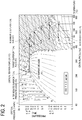
- the introduced gas F0 (state S1a) introduced into the first stage compression impeller 11 is compressed by the first stage compression impeller 11 as shown by a solid arrow in FIG. 2 and brought into a state S1b at higher pressure and higher temperature than the state S1a. Then, the first intermediate cooler 21 cools the gas under equal pressure, which is brought into a state S2a.
- state S2b ⁇ state S3a ⁇ state S3b ⁇ state S4a ⁇ state S4b ⁇ state S5a ⁇ state S5b ⁇ state S6a ⁇ state S6b ⁇ state S7a ⁇ state S7b, and the gas is brought into a state of the intermediate supercritical fluid F1 at pressure equal to or higher than the critical pressure (compression step).
- the intermediate supercritical fluid F1 in the state S7b is introduced into the cooling unit 3.
- the intermediate supercritical fluid F1 is cooled still at the supercritical pressure under equal pressure by the cooling unit 3, brought into a state S8a at around a critical temperature, changed in phase into the intermediate supercritical pressure liquid F2, and introduced into the pump unit 4 (cooling step).
- the pump unit 4 increases pressure of the intermediate supercritical pressure liquid F2 in the state S8a to target pressure at which the intermediate supercritical pressure liquid F2 can be stored under the ground or under the seafloor, entering a final state S9 in which the carbon dioxide F can be stored under the ground or under the seafloor.
- a part of the intermediate supercritical pressure liquid F2 brought into the state S8a by the cooling unit 3 is extracted by opening the flow regulating valve 92 of the flow regulating unit 9.
- an amount of the extracted intermediate supercritical pressure liquid F2 is regulated according to the opening degree of the flow regulating valve 92.
- the extracted intermediate supercritical pressure liquid F2 is reduced in pressure and turns into a low temperature liquid F5 in a state S10.
- the pressure of the low temperature liquid F5 in the state S10 is pressure corresponding to pressure on the upstream side of the sixth stage compression impeller 16 and on the downstream side of the fifth intermediate cooler 25.
- the low temperature liquid F5 is heated by heat exchange with the cooling unit 3 and vaporized still under equal pressure, and turns into a gas or a supercritical fluid in the state S6a on the upstream side of the sixth stage compression impeller 16.
- the gas or the supercritical fluid is returned to the upstream side of the sixth stage compression impeller 16 by the bypass flow path 7 and mixed into the intermediate supercritical fluid F1 flowing through the compression unit 2.
- carbon dioxide F is first compressed by the compression unit 2 on a front stage, and pressure on a rear stage at higher pressure is increased by the pump unit 4, thereby obtaining the target supercritical fluid F3 that can be stored under the ground or under the seafloor.
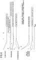
- FIG. 6 chronologically shows pressure, temperatures, and valve opening degrees in respective parts when the booster system 1 is in the partial load operation and the flow rate of carbon dioxide F (flow rate of the process gas) supplied to the booster system 1 is reduced, and solid lines represent this embodiment.
- the booster system 1 when the flow rate of the process gas is reduced, the booster system 1 once increases the opening degree of the flow regulating valve 92 ( FIG. 6 I ) to reduce the flow rate into the pump unit 4, thereby trying to reduce discharge pressure of the compression unit 2 ( FIG. 6 II). This increases the flow rate of the cooling medium flowing into the cooling unit 3, reduces the temperature on the inlet side of the pump unit 4 ( FIG. 6 III), and increases the pump discharge pressure P2, that is, final discharge pressure of the booster system 1 ( FIG. 6 IV).
- the booster system 1 can prevent the increase in pressure and allow the final discharge pressure of the booster system 1 to be controlled to the discharge target pressure more quickly at time T1.
- the flow regulating valve 97 continuously reduces the opening degree, that is, moves in a closing direction until the final discharge pressure reaches the discharge target pressure.
- the flow regulating valve 92 is closed ( FIG. 6 i ) to reduce the flow rate of the cooling medium and thus increase the pump inlet temperature ( FIG. 6 ii), thereby trying to reduce the final discharge pressure of the booster system 1.
- the flow rate of the cooling medium in the cooling unit 3 is reduced, but the flow rate into the pump unit 4 is increased instead.
- the discharge pressure (pump suction pressure P1) of the compression unit 2 and the final discharge pressure (pump discharge pressure P2) of the booster system 1 are more likely to increase ( FIG. 6 iii), making it difficult to reduce the pressure.
- pressure of the intermediate supercritical pressure liquid F2 is detected as needed by the first pressure sensor 81 provided in the middle position of the flow path L13.
- the detected pump suction pressure P1 is input to the control unit 90 of the flow regulating unit 9.
- the control unit 90 decides and regulates the opening degree of the flow regulating valve 92 through a predetermined calculation.
- the operation for regulating the opening degree is autonomously performed by the flow regulating unit 9 and the first pressure sensor 81.
- the opening degree of the flow regulating valve 92 is autonomously regulated according to the variation, and the pressure of the intermediate supercritical pressure liquid F2 is corrected to predetermined desired target pressure. This allows the target supercritical fluid F3 to be supplied at stable pressure.
- the opening degree of the flow regulating valve 97 that regulates the flow rate of the carbon dioxide F in the compression unit 2 is regulated based on the detection result of the second pressure sensor 83 provided on the outlet side of the pump unit 4.
- the pressure of the target supercritical fluid F3 is detected as needed by the second pressure sensor 83 provided in the middle position of the flow path L14.
- the detected pump discharge pressure P2 is input to the control unit 90 of the flow regulating unit 9.
- the control unit 90 decides and regulates the opening degree of the flow regulating valve 97 through a predetermined calculation.
- the above operation is autonomously performed by the flow regulating unit 9 and the second pressure sensor 83.
- the opening degree of the flow regulating valve 97 is autonomously regulated according to the variation, and the pressure of the target supercritical fluid F3 is corrected to predetermined desired target pressure. This allows the target supercritical fluid F3 to be supplied at stable pressure.
- the booster system 1 a compressor having an impeller similar to that in the compression unit 2 may be applied to a rear stage side portion at higher pressure.
- many high pressure gas seals and many compressor casings corresponding to high pressure are required.
- the booster system 1 adopts the pump unit 4 on the high pressure side.
- the pump unit 4 increases pressure of the liquid, and thus can easily seal an object fluid during the pressure increase to a high pressure state (about 15 to 60 [MPa]), thereby avoiding an increase in cost.
- the cooling unit 3 cools the intermediate supercritical fluid F1 brought into a state at the critical pressure or higher by the compression unit 2, which turns into the intermediate supercritical pressure liquid F2.
- isothermal lines rise substantially in parallel with the ordinate (pressure) and an interval between the isothermal lines is narrow.
- isothermal lines are substantially parallel to the abscissa (enthalpy) and an interval between the isothermal lines is wide.
- the intermediate supercritical fluid F1 is first cooled to the transition region by water cooling or air cooling only using the sixth intermediate cooler 26.
- the intermediate supercritical fluid F1 is in a state at the critical pressure and around the critical temperature, a large enthalpy change occurs with a small temperature change as described above, and most of cold energy required for liquefying the intermediate supercritical fluid F1 can be obtained only by water cooling or air cooling, thereby minimizing the flow rate of the cooling medium obtained by extracting the part of the intermediate supercritical fluid.
- the inside of the flow path L13 through which the intermediate supercritical pressure liquid F2 flows is under equal pressure.
- the density and the temperature of the intermediate supercritical pressure liquid F2 are inversely proportional to each other. More specifically, when the control unit 90 regulates the opening degree of the flow regulating valve 92 in an increasing direction, the density of the intermediate supercritical pressure liquid F2 increases, while the temperature decreases. On the contrary, when the opening degree of the flow regulating valve 92 is regulated in a decreasing direction, the density of the intermediate supercritical pressure liquid F2 decreases, while the temperature increases.
- the intermediate supercritical pressure liquid F2 in the state S8a introduced into the pump unit 4 increases in temperature and decreases in density, thereby entering a state (S8x).
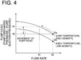
- FIG. 4 is a Q-H diagram showing a relationship of differential pressure (pump head) between the pump suction pressure P1 and the pump discharge pressure P2 of the pump unit 4 with the flow rate.
- a Q-H curve of the intermediate supercritical pressure liquid F2 in the state S8x generally has a smaller pump head than a Q-H curve of the intermediate supercritical pressure liquid F2 in the state S8a.
- the pressure of the target supercritical fluid F3 generated by the pump unit 4 decreases.
- adjusting the temperature of the intermediate supercritical pressure liquid F2 introduced into the pump unit 4 can adjust the pressure (target pressure) of the target supercritical fluid F3 finally obtained without changing a pump rotation speed or the like of the pump unit 4.
- adjusting the temperature of the intermediate supercritical pressure liquid F2 introduced into the pump unit 4 can adjust the pressure of the target supercritical fluid F3 finally obtained to certain target pressure without changing the pump rotation speed or the like of the pump unit 4.
- the booster system 1 includes the bypass flow path 7 and thus does not discharge the extracted intermediate supercritical pressure liquid F2 to the outside, thereby further improving efficiency of the entire booster system 1.
- This embodiment adopts an IGV as means for regulating the flow rate of the introduced gas F0 introduced into the compression unit 2.
- the IGV is a throttle valve that is provided in a middle of a pipe line and can regulate an opening degree. As the opening degree of the IGV decreases, the flow rate of the introduced gas F0 introduced into the compression unit 2 can be reduced.
- the IGVs are provided in the flow regulating valve 95 at an introducing portion of the first stage compression impeller 11 and in the flow regulating valve 97 at an introducing portion of the fifth stage compression impeller 15.
- FIG. 5 is a diagram showing a performance property in response to a change in the IGV opening degree of the compression unit 2.
- the IGV opening degree decreases from 100% as a fully open state to 90%, 80% ...
- the flow rate of the fluid introduced into the compression unit 2 decreases.
- a value of a limit flow rate at which a surge limit is reached is higher.
- the example in FIG. 5 shows two operation states of discharge pressure H3 and discharge pressure H4 lower than the discharge pressure H3.
- the surge limit is reached at a flow rate of 80%, while for the discharge pressure H4, the flow rate at which the surge limit is reached is extended to 70%.
- the pump head of the pump unit 4 is increased at a low flow rate, thereby allowing an amount of compression required by the compression unit 2 to be reduced.
- This allows the discharge pressure of the compression unit 2, that is, the pressure of the intermediate supercritical fluid F1 generated by the compression unit 2 to be reduced.
- reducing the IGV opening degree to reduce the discharge pressure can extend an allowable flow rate range (operation range).
- the compressor used for the compression unit 2 is not limited to the geared compressor, but other types of compressors may be adopted.
- an example of using the pump impeller as the second compression unit has been described, however, a compressor may be used.
- the compression unit 2 includes the six stages of compression impellers, and the pump unit 4 includes the two stages of pump impellers has been described.
- the present invention may adopt any number of stages of impellers as long as they can accomplish their purposes, and may adopt one or more stages of impellers as appropriate.
- the compression unit 2 and the pump unit 4 may be integrally assembled or provided separately.
- the intermediate supercritical fluid F1 generated by the compression unit 2 is cooled to the transition region to a liquid only by the sixth intermediate cooler 26, and then liquefied by the cooling unit 3 to generate the intermediate supercritical pressure liquid F2.
- the cooling unit 3 may be divided into a precooling unit and a main cooling unit, the precooling unit may include a heat exchanger that precools the intermediate supercritical fluid F1 using a cooling medium from outside, and the main cooling unit may include a heat exchanger that cools the intermediate supercritical fluid F1 using the low temperature liquid F5 from the liquid extracting and pressure reducing unit 6. With this configuration, precooling by the precooling unit can reduce cold energy required by the cooling unit 3.
- the pump unit 4 is used to obtain the target supercritical fluid F3, however, the present invention is not limited to this.
- a heating unit may be provided such that after the pump unit 4 generates a target pressure liquid F3', the target pressure liquid is introduced into the heating unit to generate a target supercritical fluid F3 at a critical temperature (31.1[°C]) or higher.
- the heating unit may constitute a heat exchanger, for example, together with the cooling unit 3, and may heat the target pressure liquid F3' with condensation heat obtained by the cooling unit 3 cooling the intermediate supercritical fluid F1 to obtain the target supercritical fluid F3.
- the opening degree of the flow regulating valve 97 (second flow regulating valve) that regulates the flow rate of the carbon dioxide F sucked into the fifth stage compression impeller 15 is regulated based on the pump discharge pressure P2 as the detection result of the second pressure sensor 83, but the present invention is not limited to this.
- the second flow regulating valve in the present invention may be provided in association with the compressor located most upstream (first stage compression impeller) or provided in association with any compressor located downstream of the most upstream position with reference to the flow direction of the object gas for compression.
Landscapes
- Engineering & Computer Science (AREA)
- Mechanical Engineering (AREA)
- General Engineering & Computer Science (AREA)
- Physics & Mathematics (AREA)
- Chemical & Material Sciences (AREA)
- Thermal Sciences (AREA)
- Chemical Kinetics & Catalysis (AREA)
- Organic Chemistry (AREA)
- Computer Hardware Design (AREA)
- Fluid Mechanics (AREA)
- General Physics & Mathematics (AREA)
- Automation & Control Theory (AREA)
- Structures Of Non-Positive Displacement Pumps (AREA)
- Control Of Positive-Displacement Pumps (AREA)
Abstract
Description
- The present invention relates to a booster system for increasing pressure of a gas.
- A booster system is a device for increasing pressure of an object gas to target pressure, and a technology is considered of using the booster system to increase pressure of carbon dioxide and store the carbon dioxide under the ground or under the seafloor, thereby reducing carbon dioxide in atmosphere. In recent years, problems such as global warming have become apparent due to an increase in emission of carbon dioxide known as greenhouse gases, and separating and collecting carbon dioxide contained in emission gases, for example, from a thermal power plant and then increasing pressure of the carbon dioxide using a booster system has been considered.
- In this booster system, a compressor configured in a multistage structure is used to gradually compress carbon dioxide, and the carbon dioxide in a state at supercritical pressure and temperature or higher is cooled to obtain carbon dioxide at target temperature and pressure optimum for transportation and storage. As such a booster system, systems disclosed in
Patent Literatures - The booster systems disclosed in
Patent Literatures - In
Patent Literature 2, a cooling temperature regulating unit is provided upstream of the pump unit to regulate a temperature of an intermediate supercritical pressure liquid generated by the cooling unit, and constantly control discharge pressure of a target supercritical fluid finally generated, that is, final discharge pressure to target pressure. More specifically, inPatent Literature 2, a pressure detection unit that detects pressure of the target supercritical fluid (carbon dioxide) having passed through a heating unit provided on a downstream side of the pump unit, and a flow regulating valve that regulates an amount of the cooling medium (intermediate supercritical fluid) supplied into the cooling unit are provided, and an opening degree of the flow regulating valve is regulated based on a deviation between a detection value detected by the pressure detection unit and a predetermined pressure range. As such, inPatent Literature 2, the temperature of the intermediate supercritical pressure liquid generated by the cooling unit and sucked into the pump unit (pump inlet temperature) is regulated. InPatent Literature 2, the pressure of the carbon dioxide heated by the heating unit is the final discharge pressure of the booster system. -
- Patent Literature 1:
JP 5826265 B2 - Patent Literature 2: International Publication No.
2015/107615 - In the above booster systems, an operation with a partial load is sometimes performed in which an amount of carbon dioxide supplied is smaller than that at a rated operation point. Also in this partial load operation, the final discharge pressure is constantly controlled to target pressure. In
Patent Literature 2, the following procedure is taken to constantly control the final discharge pressure in response to the partial load operation. Specifically, the flow regulating valve that regulates a flow rate of the cooling medium supplied into the cooling unit is closed to reduce the flow rate of the cooling medium and increase an inlet temperature of the pump unit, thereby trying to reduce the final discharge pressure. At this time, the flow rate of the cooling medium flowing into the cooling unit is reduced, but the flow rate of the cooling medium flowing into the pump unit is increased instead. Thus, the discharge pressure of the compression unit and the final discharge pressure of the system are more likely to increase, making it difficult to quickly reduce the final discharge pressure. This is because response of a temperature change in a heat exchanger that constitutes the cooling unit is slower than response of a pressure change due to a flow rate change in the booster system. - Thus, the present invention has an object to provide a booster system capable of quickly reducing and controlling final discharge pressure to target pressure even in a partial load operation.
- The present invention provides a booster system for increasing pressure of an object gas to pressure equal to or higher than target pressure that is higher than critical pressure, including: a first compression unit that compresses the object gas to intermediate pressure equal to or higher than the critical pressure and lower than the target pressure to generate an intermediate supercritical fluid; a cooling unit that extracts a part of the intermediate supercritical fluid generated by the first compression unit and uses the part of the intermediate supercritical fluid as a cooling medium, and cools the intermediate supercritical fluid generated by the first compression unit to generate an intermediate supercritical pressure liquid; a second compression unit that increases pressure of the intermediate supercritical pressure liquid generated by the cooling unit to a pressure equal to or higher than the target pressure; a first flow regulating valve that regulates a flow rate of the cooling medium into the cooling unit, the cooling medium being obtained by extracting the part of the intermediate supercritical fluid generated by the first compression unit; and a first pressure sensor that detects pressure of the intermediate supercritical pressure liquid on an inlet side of the second compression unit.
- The booster system of the present invention is characterized in that an opening degree of the first flow regulating valve is regulated based on a detection result of the first pressure sensor.
- The booster system of the present invention may include: a second flow regulating valve that regulates a suction flow rate of the object gas in the first compression unit; and a second pressure sensor that detects pressure on an outlet side of the second compression unit, wherein an opening degree of the second flow regulating valve is regulated based on a detection result of the second pressure sensor.
- The booster system of the present invention may include a first control unit that controls the opening degree of the first flow regulating valve based on the detection result of the first pressure sensor, wherein the first control unit includes a first determination unit that determines whether or not the detection result of the first pressure sensor falls within a predetermined pressure range, and a first opening degree decision unit that decides the opening degree of the first flow regulating valve based on a determination result of the first determination unit.
- The booster system of the present invention may include a second control unit that controls the opening degree of the second flow regulating valve based on the detection result of the second pressure sensor, wherein the second control unit includes a second determination unit that determines whether or not the detection result of the second pressure sensor falls within a predetermine pressure range, and a second opening degree decision unit that decides the opening degree of the second flow regulating valve based on a determination result of the second determination unit.
- In the booster system of the present invention, the first compression unit may include one or more stages of compressors, and the second compression unit may include one or more stages of pumps.
- In the booster system of the present invention, when the first compression unit includes one or more stages of compressors, the second flow regulating valve may be provided in association with the compressor located most upstream or provided in association with the compressor located downstream of the most upstream position with reference to a flow direction of the object gas.
- In the booster system of the present invention, the second compression unit may increase pressure of the intermediate supercritical pressure liquid to generate a target supercritical fluid.
- In the booster system of the present invention, the first flow regulating valve may reduce pressure of the extracted part of the intermediate supercritical fluid to generate a liquid or gas-liquid two-phase cooling medium.
- The booster system of the present invention may include a bypass flow path through which the cooling medium used for cooling by the cooling unit is returned to the first compression unit.
- According to the booster system of the present invention, the opening degree of the first flow regulating valve that regulates the flow rate of the cooling medium obtained by extracting the part of the intermediate supercritical fluid supplied into the cooling unit is regulated based on suction side pressure detected on the inlet side of the second compression unit. Increasing the opening degree of the first flow regulating valve, that is, opening the first flow regulating valve increases the flow rate of the cooling medium obtained by extracting the part of the intermediate supercritical fluid flowing into the cooling unit, while reduces the flow rate of the intermediate supercritical fluid flowing into the second compression unit. Specifically, the booster system of the present invention regulates the opening degree of the first flow regulating valve to control discharge pressure of the first compression unit. Thus, if the system is in a partial load operation state, the first flow regulating valve is once opened to reduce the flow rate of the intermediate supercritical fluid flowing into the second compression unit, thereby trying to reduce the discharge pressure of the first compression unit. This increases the flow rate of the cooling medium obtained by extracting the part of the intermediate supercritical fluid flowing into the cooling unit, reduces the inlet temperature of the second compression unit, and starts to increase the discharge pressure of the second compression unit, that is, final discharge pressure. However, since response of a pressure change due to a flow rate change in the system is faster than response of a temperature change in the cooling unit, typically, a heat exchanger, the reduction in the inlet temperature of the second compression unit has a low impact on the increase in the final discharge pressure. As a result, according to the present invention, the increase in the final discharge pressure can be prevented to allow quicker control to the target pressure.
-
- [
FIG. 1] FIG. 1 is schematic system diagram of a booster system according to an embodiment of the present invention. - [
FIG. 2] FIG. 2 is a P-h diagram showing a state of carbon dioxide in connection with the booster system according to the embodiment. - [
FIG. 3] FIG. 3 shows a configuration of a control unit in connection with the booster system according to the embodiment. - [
FIG. 4] FIG. 4 is a Q-H diagram showing changes in performance property of a pump unit in response to a state of a fluid introduced into the pump unit in connection with the booster system according to the embodiment. - [
FIG. 5] FIG. 5 is a diagram showing an opening degree of a flow regulating valve (IGV) of a compression unit and a performance property in response to a flow rate of a fluid introduced into the compression unit in connection with the booster system according to the embodiment. - [
FIG. 6] FIG. 6 illustrates an operation of the booster system according to this embodiment. - Now, with reference to the accompanying drawings, an embodiment of a booster system according to the present invention will be described.
- A
booster system 1 according to this embodiment is a system for increasing pressure of carbon dioxide F in a gas state as an object gas for compression to pressure equal to or higher than target pressure that is higher than critical pressure. - As shown in
FIG. 1 , thebooster system 1 includes acompression unit 2 that takes in and compresses carbon dioxide F, acooling unit 3 that cools an intermediate supercritical fluid generated by thecompression unit 2 to around a critical temperature to generate an intermediate supercritical pressure liquid, and apump unit 4 that increases pressure of the intermediate supercritical pressure liquid generated by thecooling unit 3 to pressure equal to or higher than target pressure. - The
booster system 1 also includes a liquid extracting andpressure reducing unit 6 that is provided between thecooling unit 3 and thepump unit 4 to extract carbon dioxide F (an intermediate supercritical pressure liquid F2), and abypass flow path 7 through which the carbon dioxide F from the liquid extracting andpressure reducing unit 6 is returned to thecompression unit 2. - The
booster system 1 includes, as apressure detection unit 8, afirst pressure sensor 81 that detects pressure (pump suction pressure P1) of carbon dioxide F on an inlet side of thepump unit 4, and asecond pressure sensor 83 that detects pressure (pump discharge pressure P2) of carbon dioxide F on an outlet side of thepump unit 4. The pump suction pressure P1 is also discharge pressure of thecompression unit 2. Thebooster system 1 also includes aflow regulating valve 92 as aflow regulating unit 9 that regulates a flow rate of the carbon dioxide F extracted by the liquid extracting andpressure reducing unit 6, and an opening degree of theflow regulating valve 92 is regulated based on the pump suction pressure P1 detected by thefirst pressure sensor 81 to control the discharge pressure of thecompression unit 2. Specifically, thebooster system 1 of this embodiment is characterized in that theflow regulating valve 92 controls the discharge pressure of thecompression unit 2, that is, the pump suction pressure P1. - Now, components of the
booster system 1 will be described, and then operations of thebooster system 1 and operations/effects of thebooster system 1 will be described in this order. - The
compression unit 2 constitutes a first compression unit in the present invention, and includes a geared compressor of a multiaxis and multistage configuration in which a plurality of impellers are interlocked via gears. - The
compression unit 2 includes a plurality ofimpellers 10 provided in multiple stages (six stages in this embodiment), and a plurality ofintermediate coolers 20 each provided between twoconsecutive impellers 10 and between animpeller 10 and thecooling unit 3. Thecompression unit 2 uses the taken carbon dioxide F as an introduced gas F0 and repeats compression and cooling to compress the carbon dioxide F to a pressure state at intermediate pressure equal to or higher than critical pressure and lower than target pressure to generate an intermediate supercritical fluid F1. - The critical pressure of the carbon dioxide F is 7.4 [MPa], and as the target pressure, for example, 15 [MPa] is set which is a value higher than the critical pressure. As the intermediate pressure of the intermediate supercritical fluid F1 generated by the
compression unit 2, for example, 10 [MPa] is set. However, the values of the target pressure and the intermediate pressure are decided as appropriate according to the critical pressure of the object gas, and do not limit the present invention. - The
compression unit 2 includes a first stage compression impeller 11, a firstintermediate cooler 21, a second stage compression impeller 12, a secondintermediate cooler 22, a third stage compression impeller 13, a thirdintermediate cooler 23, a fourth stage compression impeller 14, a fourthintermediate cooler 24, a fifth stage compression impeller 15, a fifthintermediate cooler 25, a sixth stage compression impeller 16, and a sixth intermediate cooler 26 provided in this order from an upstream side toward a downstream side of the flow of the taken carbon dioxide F. These components of thecompression unit 2 are connected by flow paths L1, L2, L3, L4, L5, L6, L7, L8, L9, L10, L11 constituted by pipe devices so that the carbon dioxide F as a medium to be compressed can flow between the components. - The
compression unit 2 includes aflow regulating valve 95 that regulates a flow rate of carbon dioxide F sucked into the first stage compression impeller 11, and aflow regulating valve 97 that regulates a flow rate of carbon dioxide F sucked into the fifth stage compression impeller 15. Theflow regulating valve 95 and theflow regulating valve 97 are constituted by, for example, inlet guide vanes (IGV). - Although not shown, the
compression unit 2 includes a device for removing water on a downstream side of the fourthintermediate cooler 24, and includes theflow regulating valve 95 on the inlet side of the first stage compression impeller 11 in order to regulate operation pressure of the water removal device. Thebooster system 1 includes theflow regulating valve 97 to regulate final discharge pressure. Without the water removal device, theflow regulating valve 95 associated with the first stage compression impeller 11 located most upstream is regulated to regulate the final discharge pressure of thebooster system 1. In this case, theflow regulating valve 97 is omitted. - In this embodiment, an opening degree of the
flow regulating valve 97 is regulated based on a detection result of thesecond pressure sensor 83, that is, the pump discharge pressure P2. - The
cooling unit 3 is connected to a downstream side of the sixth intermediate cooler 26 by the flow path L12, cools the intermediate supercritical fluid F1 generated by the sixth stage compression impeller 16 as a final stage of thecompression unit 2 to around a critical temperature and liquefies the intermediate supercritical fluid F1 to generate an intermediate supercritical pressure liquid F2. - The
cooling unit 3 includes a heat exchanger that introduces a low temperature liquid F5 from the liquid extracting andpressure reducing unit 6 described later and uses the low temperature liquid F5 as a cooling medium to cool the intermediate supercritical fluid F1. Heat exchange in thecooling unit 3 is performed with aheat exchanger 62 in the liquid extracting andpressure reducing unit 6 described later. - When the
cooling unit 3 cools the intermediate supercritical fluid F1 to around the critical temperature, cooling to a temperature of ±20[°C] of the critical temperature is preferable, cooling to a temperature of ±15[°C] of the critical temperature is more preferable, and cooling to a temperature of ±10[°C] of the critical temperature is most preferable. - The
pump unit 4 constitutes a second compression unit in the present invention. Thepump unit 4 is connected to a downstream side of thecooling unit 3 by the flow path L13, introduces the intermediate supercritical pressure liquid F2 generated by passing through thecooling unit 3 and increases pressure of the intermediate supercritical pressure liquid F2 to a pressure state at target pressure to generate a target supercritical fluid F3. In this embodiment, thepump unit 4 adopts a two-stage configuration including a firststage pump impeller 41 and a secondstage pump impeller 43. However, thepump unit 4 may adopt any configuration as long as it can increase pressure of the intermediate supercritical pressure liquid F2 to the target pressure. - As described above, the
first pressure sensor 81 is provided in the flow path L13, and continuously detects pressure (pump suction pressure P1) of the intermediate supercritical pressure liquid F2 flowing through the flow path L13. - Further, the flow path L14 is connected to the downstream side of the
pump unit 4. The target supercritical fluid F3 generated by compression in thepump unit 4 flows through the flow path L14, and is supplied to external equipment connected to the downstream side. - The
second pressure sensor 83 is provided in the flow path L14, and continuously detects pressure (pump discharge pressure P2) of the target supercritical fluid F3 flowing through the flow path L14. - The liquid extracting and
pressure reducing unit 6 is provided between the coolingunit 3 and thepump unit 4, and uses a low temperature liquid F5 obtained by extracting a part of the intermediate supercritical pressure liquid F2 from thecooling unit 3 to cool the intermediate supercritical fluid F1 in thecooling unit 3. Heat exchange caused by the cooling heats the low temperature liquid F5 itself. - Specifically, the liquid extracting and
pressure reducing unit 6 includes abranch pipe line 61 having one end connected to the flow path L13 so as to branch off from the flow path L13 between the coolingunit 3 and thepump unit 4, and aheat exchanger 62 to which the other end of thebranch pipe line 61 is connected and that performs heat exchange with thecooling unit 3. Further, theflow regulating valve 92 is provided in a middle position of thebranch pipe line 61, and an opening degree of theflow regulating valve 92 is regulated to increase/decrease the flow rate of the intermediate supercritical pressure liquid F2 flowing toward theheat exchanger 62. Increasing the opening degree of theflow regulating valve 92, that is, opening theflow regulating valve 92 increases the flow rate of the intermediate supercritical pressure liquid F2 flowing toward theheat exchanger 62, while reduces the flow rate of the intermediate supercritical pressure liquid F2 flowing toward thepump unit 4. Reducing the opening degree of theflow regulating valve 92, that is, closing theflow regulating valve 92 causes the opposite action. Theflow regulating valve 92 constitutes a first flow regulating valve in the present invention. - The
bypass flow path 7 returns the low temperature liquid F5 from the liquid extracting andpressure reducing unit 6 to an upstream side of the sixth stage compression impeller 16 of thecompression unit 2. Thebypass flow path 7 has one end connected to theheat exchanger 62 of the liquid extracting andpressure reducing unit 6, and the other end connected to the flow path L10 between the sixth stage compression impeller 16 and the fifthintermediate cooler 25. - The
pressure detection unit 8 includes thefirst pressure sensor 81 provided in the middle of the flow path L13 and thesecond pressure sensor 83 provided in the middle of the flow path L14. Thefirst pressure sensor 81 measures a pressure value of the intermediate supercritical pressure liquid F2 flowing through the flow path L13, that is, the pump suction pressure P1 of thepump unit 4, and thesecond pressure sensor 83 measures a pressure value of the target supercritical fluid F3 flowing through the flow path L14, that is, the pump discharge pressure P2 of thepump unit 4. - The pump suction pressure P1 and the pump discharge pressure P2 measured by the
pressure detection unit 8 are transmitted to acontrol unit 90 of aflow regulating unit 9 described later. In this embodiment, the pump suction pressure P1 corresponds to discharge side pressure of thecompression unit 2, and the pump discharge pressure P2 corresponds to final discharge pressure of thebooster system 1. - The
flow regulating unit 9 includes thecontrol unit 90 to which thefirst pressure sensor 81 and thesecond pressure sensor 83 of thepressure detection unit 8 are electrically connected, and theflow regulating valve 92 and theflow regulating valve 97 each having an opening degree regulated by an instruction from thecontrol unit 90. - The opening degree of the
flow regulating valve 92 is regulated to reduce pressure of the intermediate supercritical pressure liquid F2 extracted from the flow path L13 by the Joule-Thomson effect to generate the low temperature liquid F5. The opening degree of theflow regulating valve 97 is regulated to increase/decrease the flow rate of the carbon dioxide F sucked into the fifth stage compression impeller 15. The opening degrees of theflow regulating valve 92 and theflow regulating valve 97 are controlled by thecontrol unit 90. Although not shown, thecontrol unit 90 is associated with the first stage compression impeller 11 located on a most upstream side of thecompression unit 2, and thecontrol unit 90 can regulate the opening degree of theflow regulating valve 95 that regulates the flow rate of the carbon dioxide F supplied into the first stage compression impeller 11. - The
control unit 90 includes, for example as shown inFIG. 3 , adetermination unit 91A connected to thefirst pressure sensor 81 and thesecond pressure sensor 83, and an openingdegree decision unit 91B connected to thedetermination unit 91A. Thedetermination unit 91A includes both the first determination unit and the second determination unit in the present invention, and the openingdegree decision unit 91B includes both the first opening degree decision unit and the second opening degree decision unit in the present invention. - The
determination unit 91A is electrically connected to thepressure detection unit 8, and performs a determination processing whether or not the pump suction pressure P1 and the pump discharge pressure P2 as detection values of thefirst pressure sensor 81 and thesecond pressure sensor 83 of thepressure detection unit 8 fall within preset determination values Ps1, Ps2. The determination values Ps1, Ps2 are defined within a numerical range including the target pressure of the target supercritical fluid F3 generated by thebooster system 1, and input to thedetermination unit 91A by input means (not shown), and stored and held in thedetermination unit 91A. - The
determination unit 91A calculates difference amounts ΔP1, ΔP2 between the stored predetermined determination values Ps1, Ps2 and the pump suction pressure P1 and the pump discharge pressure P2 as the detection values. Thedetermination unit 91A transfers the difference amounts ΔP1, ΔP2 as determination results to the openingdegree decision unit 91B. - The opening
degree decision unit 91B performs a predetermined calculation based on the difference amounts ΔP1, ΔP2 obtained from thedetermination unit 91A to calculate the opening degrees of theflow regulating valve 92 and theflow regulating valve 97. More specifically, first, the difference amounts ΔP1, ΔP2 of the pressure values and an amount of increase/decrease in the flow rate required for eliminating the difference amounts ΔP1, ΔP2 are obtained from a predetermined relational expression. The relational expression is empirically obtained according to performance requirements or the like of thebooster system 1. - The opening
degree decision unit 91B calculates the opening degrees of theflow regulating valve 92 and theflow regulating valve 97 based on the amount of increase/decrease in the flow rate obtained by the relational expression. A relationship between the amount of increase/decrease in the flow rate and the opening degrees of theflow regulating valve 92 and theflow regulating valve 97 are decided according to performance requirements or the like of the flow regulating valve used for theflow regulating valve 92. - The opening
degree decision unit 91B transfers instruction information on the decided increase/decrease in the opening degree to theflow regulating valve 92 and theflow regulating valve 97. Theflow regulating valve 92 and theflow regulating valve 97 having obtained the instruction information from the openingdegree decision unit 91B regulate their opening degrees, that is, increase/decrease or keep the opening degrees according to the instruction information. - Next, with reference to a P-h diagram in
FIG. 2 , a state change of the carbon dioxide F in thebooster system 1, that is, a pressure increasing procedure of the carbon dioxide F will be described. - In the
compression unit 2, the introduced gas F0 (state S1a) introduced into the first stage compression impeller 11 is compressed by the first stage compression impeller 11 as shown by a solid arrow inFIG. 2 and brought into a state S1b at higher pressure and higher temperature than the state S1a. Then, the firstintermediate cooler 21 cools the gas under equal pressure, which is brought into a state S2a. Then, compression and cooling are thus repeated to cause state changes: state S2b → state S3a → state S3b → state S4a → state S4b → state S5a → state S5b → state S6a → state S6b → state S7a → state S7b, and the gas is brought into a state of the intermediate supercritical fluid F1 at pressure equal to or higher than the critical pressure (compression step). - Then, the intermediate supercritical fluid F1 in the state S7b is introduced into the
cooling unit 3. The intermediate supercritical fluid F1 is cooled still at the supercritical pressure under equal pressure by thecooling unit 3, brought into a state S8a at around a critical temperature, changed in phase into the intermediate supercritical pressure liquid F2, and introduced into the pump unit 4 (cooling step). - The
pump unit 4 increases pressure of the intermediate supercritical pressure liquid F2 in the state S8a to target pressure at which the intermediate supercritical pressure liquid F2 can be stored under the ground or under the seafloor, entering a final state S9 in which the carbon dioxide F can be stored under the ground or under the seafloor. - Here, a part of the intermediate supercritical pressure liquid F2 brought into the state S8a by the
cooling unit 3 is extracted by opening theflow regulating valve 92 of theflow regulating unit 9. At this time, an amount of the extracted intermediate supercritical pressure liquid F2 is regulated according to the opening degree of theflow regulating valve 92. The extracted intermediate supercritical pressure liquid F2 is reduced in pressure and turns into a low temperature liquid F5 in a state S10. The pressure of the low temperature liquid F5 in the state S10 is pressure corresponding to pressure on the upstream side of the sixth stage compression impeller 16 and on the downstream side of the fifthintermediate cooler 25. - The low temperature liquid F5 is heated by heat exchange with the
cooling unit 3 and vaporized still under equal pressure, and turns into a gas or a supercritical fluid in the state S6a on the upstream side of the sixth stage compression impeller 16. The gas or the supercritical fluid is returned to the upstream side of the sixth stage compression impeller 16 by thebypass flow path 7 and mixed into the intermediate supercritical fluid F1 flowing through thecompression unit 2. - Now, effects of the
booster system 1 according to the embodiment will be described. - With the
booster system 1 according to this embodiment, carbon dioxide F is first compressed by thecompression unit 2 on a front stage, and pressure on a rear stage at higher pressure is increased by thepump unit 4, thereby obtaining the target supercritical fluid F3 that can be stored under the ground or under the seafloor. - Next, with reference to
FIG. 6 , operations and effects of thebooster system 1 will be described which are obtained by regulating the opening degree of theflow regulating valve 92 based on the detection result of thefirst pressure sensor 81, in other words, theflow regulating valve 92 controlling discharge pressure of thecompression unit 2. -
FIG. 6 chronologically shows pressure, temperatures, and valve opening degrees in respective parts when thebooster system 1 is in the partial load operation and the flow rate of carbon dioxide F (flow rate of the process gas) supplied to thebooster system 1 is reduced, and solid lines represent this embodiment. - In
FIG. 6 , when the flow rate of the process gas is reduced, thebooster system 1 once increases the opening degree of the flow regulating valve 92 (FIG. 6 I ) to reduce the flow rate into thepump unit 4, thereby trying to reduce discharge pressure of the compression unit 2 (FIG. 6 II). This increases the flow rate of the cooling medium flowing into thecooling unit 3, reduces the temperature on the inlet side of the pump unit 4 (FIG. 6 III), and increases the pump discharge pressure P2, that is, final discharge pressure of the booster system 1 (FIG. 6 IV). However, since response of a pressure change due to a flow rate change in thebooster system 1 is faster than response of a temperature change in the heat exchanger that constitutes thecooling unit 3, the reduction in the pump inlet temperature has a low impact on the increase in the final discharge pressure (pump discharge pressure P2) of thebooster system 1. As a result, thebooster system 1 can prevent the increase in pressure and allow the final discharge pressure of thebooster system 1 to be controlled to the discharge target pressure more quickly at time T1. - During this process, the
flow regulating valve 97 continuously reduces the opening degree, that is, moves in a closing direction until the final discharge pressure reaches the discharge target pressure. - On the other hand, a conventional control method disclosed in
Patent Literature 2 is as described below. Dashed lines inFIG. 6 represent the conventional control method. - In the conventional control method, the
flow regulating valve 92 is closed (FIG. 6 i ) to reduce the flow rate of the cooling medium and thus increase the pump inlet temperature (FIG. 6 ii), thereby trying to reduce the final discharge pressure of thebooster system 1. At this time, the flow rate of the cooling medium in thecooling unit 3 is reduced, but the flow rate into thepump unit 4 is increased instead. Thus, the discharge pressure (pump suction pressure P1) of thecompression unit 2 and the final discharge pressure (pump discharge pressure P2) of thebooster system 1 are more likely to increase (FIG. 6 iii), making it difficult to reduce the pressure. This is because response of a pressure change due to a flow rate change in thebooster system 1 is faster than response of a temperature change in the heat exchanger that constitutes thecooling unit 3. As a result, as shown inFIG. 6 , it takes time T2 slower than in this embodiment to control to the discharge target pressure. - During this control process, pressure of the intermediate supercritical pressure liquid F2 is detected as needed by the
first pressure sensor 81 provided in the middle position of the flow path L13. The detected pump suction pressure P1 is input to thecontrol unit 90 of theflow regulating unit 9. Thecontrol unit 90 decides and regulates the opening degree of theflow regulating valve 92 through a predetermined calculation. The operation for regulating the opening degree is autonomously performed by theflow regulating unit 9 and thefirst pressure sensor 81. Thus, even if the pressure of the intermediate supercritical pressure liquid F2 varies, the opening degree of theflow regulating valve 92 is autonomously regulated according to the variation, and the pressure of the intermediate supercritical pressure liquid F2 is corrected to predetermined desired target pressure. This allows the target supercritical fluid F3 to be supplied at stable pressure. - Next, in the
booster system 1, the opening degree of theflow regulating valve 97 that regulates the flow rate of the carbon dioxide F in thecompression unit 2 is regulated based on the detection result of thesecond pressure sensor 83 provided on the outlet side of thepump unit 4. - This allows the final discharge pressure of the
booster system 1 to be controlled without interfering with the opening degree of theflow regulating valve 92. - During this control process, the pressure of the target supercritical fluid F3 is detected as needed by the
second pressure sensor 83 provided in the middle position of the flow path L14. The detected pump discharge pressure P2 is input to thecontrol unit 90 of theflow regulating unit 9. Thecontrol unit 90 decides and regulates the opening degree of theflow regulating valve 97 through a predetermined calculation. The above operation is autonomously performed by theflow regulating unit 9 and thesecond pressure sensor 83. Thus, even if the pressure of the target supercritical fluid F3 varies due to a disturbance factor or the like, the opening degree of theflow regulating valve 97 is autonomously regulated according to the variation, and the pressure of the target supercritical fluid F3 is corrected to predetermined desired target pressure. This allows the target supercritical fluid F3 to be supplied at stable pressure. - Next, in the
booster system 1, a compressor having an impeller similar to that in thecompression unit 2 may be applied to a rear stage side portion at higher pressure. However, in this case, many high pressure gas seals and many compressor casings corresponding to high pressure are required. In the respect, thebooster system 1 adopts thepump unit 4 on the high pressure side. Thepump unit 4 increases pressure of the liquid, and thus can easily seal an object fluid during the pressure increase to a high pressure state (about 15 to 60 [MPa]), thereby avoiding an increase in cost. - Also, the
cooling unit 3 cools the intermediate supercritical fluid F1 brought into a state at the critical pressure or higher by thecompression unit 2, which turns into the intermediate supercritical pressure liquid F2. - As shown in the P-h diagram in
FIG. 2 , at pressure lower than the critical pressure, isothermal lines rise substantially in parallel with the ordinate (pressure) and an interval between the isothermal lines is narrow. On the other hand, in a transition region at the critical pressure or higher and around the critical temperature, isothermal lines are substantially parallel to the abscissa (enthalpy) and an interval between the isothermal lines is wide. Thus, in the transition region, during a state change of the carbon dioxide F under equal pressure, a larger enthalpy change occurs with a smaller temperature change. - The intermediate supercritical fluid F1 is first cooled to the transition region by water cooling or air cooling only using the sixth
intermediate cooler 26. However, since the intermediate supercritical fluid F1 is in a state at the critical pressure and around the critical temperature, a large enthalpy change occurs with a small temperature change as described above, and most of cold energy required for liquefying the intermediate supercritical fluid F1 can be obtained only by water cooling or air cooling, thereby minimizing the flow rate of the cooling medium obtained by extracting the part of the intermediate supercritical fluid. - Further, the inside of the flow path L13 through which the intermediate supercritical pressure liquid F2 flows is under equal pressure. Thus, according to the opening degree of the
flow regulating valve 92 of theflow regulating unit 9, the density and the temperature of the intermediate supercritical pressure liquid F2 are inversely proportional to each other. More specifically, when thecontrol unit 90 regulates the opening degree of theflow regulating valve 92 in an increasing direction, the density of the intermediate supercritical pressure liquid F2 increases, while the temperature decreases. On the contrary, when the opening degree of theflow regulating valve 92 is regulated in a decreasing direction, the density of the intermediate supercritical pressure liquid F2 decreases, while the temperature increases. - Thus, for example, when the opening degree of the
flow regulating valve 92 is regulated in the decreasing direction, the intermediate supercritical pressure liquid F2 in the state S8a introduced into thepump unit 4 increases in temperature and decreases in density, thereby entering a state (S8x). -
FIG. 4 is a Q-H diagram showing a relationship of differential pressure (pump head) between the pump suction pressure P1 and the pump discharge pressure P2 of thepump unit 4 with the flow rate. As show inFIG. 4 , a Q-H curve of the intermediate supercritical pressure liquid F2 in the state S8x generally has a smaller pump head than a Q-H curve of the intermediate supercritical pressure liquid F2 in the state S8a. Specifically, as the temperature of the intermediate supercritical pressure liquid F2 increases and the density thereof decreases, the pressure of the target supercritical fluid F3 generated by thepump unit 4 decreases. - As such, adjusting the temperature of the intermediate supercritical pressure liquid F2 introduced into the
pump unit 4 can adjust the pressure (target pressure) of the target supercritical fluid F3 finally obtained without changing a pump rotation speed or the like of thepump unit 4. - Further, as shown in
FIG. 4 , even under a condition at a low flow rate, adjusting the temperature of the intermediate supercritical pressure liquid F2 introduced into thepump unit 4 can adjust the pressure of the target supercritical fluid F3 finally obtained to certain target pressure without changing the pump rotation speed or the like of thepump unit 4. - This allows target pressure to be obtained without providing, for example, a variable speed motor or the like in the
pump unit 4. - The
booster system 1 includes thebypass flow path 7 and thus does not discharge the extracted intermediate supercritical pressure liquid F2 to the outside, thereby further improving efficiency of theentire booster system 1. - This embodiment adopts an IGV as means for regulating the flow rate of the introduced gas F0 introduced into the
compression unit 2. The IGV is a throttle valve that is provided in a middle of a pipe line and can regulate an opening degree. As the opening degree of the IGV decreases, the flow rate of the introduced gas F0 introduced into thecompression unit 2 can be reduced. In this embodiment, the IGVs are provided in theflow regulating valve 95 at an introducing portion of the first stage compression impeller 11 and in theflow regulating valve 97 at an introducing portion of the fifth stage compression impeller 15. -
FIG. 5 is a diagram showing a performance property in response to a change in the IGV opening degree of thecompression unit 2. As can be seen fromFIG. 5 , as the IGV opening degree decreases from 100% as a fully open state to 90%, 80% ..., the flow rate of the fluid introduced into thecompression unit 2 decreases. At higher discharge pressure of thecompression unit 2, a value of a limit flow rate at which a surge limit is reached is higher. The example inFIG. 5 shows two operation states of discharge pressure H3 and discharge pressure H4 lower than the discharge pressure H3. For the discharge pressure H3, the surge limit is reached at a flow rate of 80%, while for the discharge pressure H4, the flow rate at which the surge limit is reached is extended to 70%. Thus, the pump head of thepump unit 4 is increased at a low flow rate, thereby allowing an amount of compression required by thecompression unit 2 to be reduced. This allows the discharge pressure of thecompression unit 2, that is, the pressure of the intermediate supercritical fluid F1 generated by thecompression unit 2 to be reduced. - As such, reducing the IGV opening degree to reduce the discharge pressure can extend an allowable flow rate range (operation range).
- This can extend a flow rate range (operation range) of the target supercritical fluid F3 obtained by the
booster system 1. - The preferred embodiment of the present invention has been described above. The components listed in the above embodiment may be chosen or changed to other components without departing from the gist of the present invention as described below.
- In this embodiment, an example of using the geared compressor for the
compression unit 2 as the first compression unit has been described. However, the compressor used for thecompression unit 2 is not limited to the geared compressor, but other types of compressors may be adopted. Also, an example of using the pump impeller as the second compression unit has been described, however, a compressor may be used. Also, an example in which thecompression unit 2 includes the six stages of compression impellers, and thepump unit 4 includes the two stages of pump impellers has been described. However, the present invention may adopt any number of stages of impellers as long as they can accomplish their purposes, and may adopt one or more stages of impellers as appropriate. Further, thecompression unit 2 and thepump unit 4 may be integrally assembled or provided separately. - In this embodiment, the intermediate supercritical fluid F1 generated by the
compression unit 2 is cooled to the transition region to a liquid only by the sixthintermediate cooler 26, and then liquefied by thecooling unit 3 to generate the intermediate supercritical pressure liquid F2. However, the present invention is not limited to this. For example, thecooling unit 3 may be divided into a precooling unit and a main cooling unit, the precooling unit may include a heat exchanger that precools the intermediate supercritical fluid F1 using a cooling medium from outside, and the main cooling unit may include a heat exchanger that cools the intermediate supercritical fluid F1 using the low temperature liquid F5 from the liquid extracting andpressure reducing unit 6. With this configuration, precooling by the precooling unit can reduce cold energy required by thecooling unit 3. - Also, in this embodiment, the
pump unit 4 is used to obtain the target supercritical fluid F3, however, the present invention is not limited to this. For example, a heating unit may be provided such that after thepump unit 4 generates a target pressure liquid F3', the target pressure liquid is introduced into the heating unit to generate a target supercritical fluid F3 at a critical temperature (31.1[°C]) or higher. The heating unit may constitute a heat exchanger, for example, together with thecooling unit 3, and may heat the target pressure liquid F3' with condensation heat obtained by thecooling unit 3 cooling the intermediate supercritical fluid F1 to obtain the target supercritical fluid F3. - Also, in this embodiment, the opening degree of the flow regulating valve 97 (second flow regulating valve) that regulates the flow rate of the carbon dioxide F sucked into the fifth stage compression impeller 15 is regulated based on the pump discharge pressure P2 as the detection result of the
second pressure sensor 83, but the present invention is not limited to this. Specifically, the second flow regulating valve in the present invention may be provided in association with the compressor located most upstream (first stage compression impeller) or provided in association with any compressor located downstream of the most upstream position with reference to the flow direction of the object gas for compression. -
- 1
- booster system
- 2
- compression unit
- 3
- cooling unit
- 4
- pump unit
- 6
- liquid extracting and pressure reducing unit
- 7
- bypass flow path
- 8
- pressure detection unit
- 9
- flow regulating unit
- 10
- impeller
- 11
- first stage compression impeller
- 12
- second stage compression impeller
- 13
- third stage compression impeller
- 14
- fourth stage compression impeller
- 15
- fifth stage compression impeller
- 16
- sixth stage compression impeller
- 20
- intermediate cooler
- 21
- first intermediate cooler
- 22
- second intermediate cooler
- 23
- third intermediate cooler
- 24
- fourth intermediate cooler
- 25
- fifth intermediate cooler
- 26
- sixth intermediate cooler
- 41
- first stage pump impeller
- 43
- second stage pump impeller
- 61
- branch pipe line
- 62
- heat exchanger
- 81
- first pressure sensor
- 83
- second pressure sensor
- 90
- control unit
- 91A
- determination unit
- 91B
- opening degree decision unit
- 92
- flow regulating valve
- 95
- flow regulating valve
- 97
- flow regulating valve
Claims (9)
- A booster system for increasing pressure of an object gas to pressure equal to or higher than target pressure that is higher than critical pressure, comprising:a first compression unit that compresses the object gas to intermediate pressure equal to or higher than the critical pressure and lower than the target pressure to generate an intermediate supercritical fluid;a cooling unit that extracts a part of the intermediate supercritical fluid generated by the first compression unit and uses the part of the intermediate supercritical fluid as a cooling medium, and cools the intermediate supercritical fluid generated by the first compression unit to generate an intermediate supercritical pressure liquid;a second compression unit that increases pressure of the intermediate supercritical pressure liquid generated by the cooling unit to a pressure equal to or higher than the target pressure;a first flow regulating valve that regulates a flow rate of the cooling medium into the cooling unit, the cooling medium being obtained by extracting the part of the intermediate supercritical fluid generated by the first compression unit; anda first pressure sensor that detects pressure of the intermediate supercritical pressure liquid on an inlet side of the second compression unit,wherein an opening degree of the first flow regulating valve is regulated based on a detection result of the first pressure sensor.
- The booster system according to claim 1, comprising:a second flow regulating valve that regulates a suction flow rate of the object gas in the first compression unit; anda second pressure sensor that detects pressure on an outlet side of the second compression unit,wherein an opening degree of the second flow regulating valve is regulated based on a detection result of the second pressure sensor.
- The booster system according to claim 1 or 2, comprising a first control unit that controls the opening degree of the first flow regulating valve based on the detection result of the first pressure sensor,
wherein the first control unit includes a first determination unit that determines whether or not the detection result of the first pressure sensor falls within a predetermined pressure range, and a first opening degree decision unit that decides the opening degree of the first flow regulating valve based on a determination result of the first determination unit. - The booster system according to claim 2 or 3, comprising a second control unit that controls the opening degree of the second flow regulating valve based on the detection result of the second pressure sensor,
wherein the second control unit includes a second determination unit that determines whether or not the detection result of the second pressure sensor falls within a predetermine pressure range, and a second opening degree decision unit that decides the opening degree of the second flow regulating valve based on a determination result of the second determination unit. - The booster system according to any one of claims 1 to 4, wherein the first compression unit includes one or more stages of compressors, and
the second compression unit includes one or more stages of pumps or compressors. - The booster system according to any one of claims 2 to 5, wherein the first compression unit includes one or more stages of compressors, and
the second flow regulating valve is provided in association with the compressor located most upstream or provided in association with the compressor located downstream of the most upstream position with reference to a flow direction of the object gas. - The booster system according to any one of claims 1 to 6, wherein the second compression unit increases pressure of the intermediate supercritical pressure liquid to generate a target supercritical fluid.
- The booster system according to any one of claims 1 to 7, wherein the first flow regulating valve reduces pressure of the extracted part of the intermediate supercritical fluid to generate a liquid or gas-liquid two-phase cooling medium.
- The booster system according to any one of claims 1 to 8, comprising a bypass flow path through which the cooling medium used for cooling by the cooling unit is returned to the first compression unit.
Applications Claiming Priority (1)
| Application Number | Priority Date | Filing Date | Title |
|---|---|---|---|
| PCT/JP2016/000666 WO2017138036A1 (en) | 2016-02-09 | 2016-02-09 | Booster system |
Publications (3)
| Publication Number | Publication Date |
|---|---|
| EP3415758A1 true EP3415758A1 (en) | 2018-12-19 |
| EP3415758A4 EP3415758A4 (en) | 2018-12-19 |
| EP3415758B1 EP3415758B1 (en) | 2019-06-05 |
Family
ID=59563829
Family Applications (1)
| Application Number | Title | Priority Date | Filing Date |
|---|---|---|---|
| EP16889745.2A Active EP3415758B1 (en) | 2016-02-09 | 2016-02-09 | Booster system |
Country Status (4)
| Country | Link |
|---|---|
| US (1) | US11022369B2 (en) |
| EP (1) | EP3415758B1 (en) |
| JP (1) | JP6537639B2 (en) |
| WO (1) | WO2017138036A1 (en) |
Cited By (1)
| Publication number | Priority date | Publication date | Assignee | Title |
|---|---|---|---|---|
| DE102024203398A1 (en) | 2024-04-12 | 2025-10-16 | Siemens Energy Global GmbH & Co. KG | Plant and process for the liquefaction of carbon dioxide |
Families Citing this family (6)
| Publication number | Priority date | Publication date | Assignee | Title |
|---|---|---|---|---|
| US11022369B2 (en) * | 2016-02-09 | 2021-06-01 | Mitsubishi Heavy Industries Compressor Corporation | Booster system |
| JP7222833B2 (en) * | 2019-07-03 | 2023-02-15 | 株式会社神戸製鋼所 | Compressor and method for adjusting seal gas in compressor |
| US12123646B2 (en) | 2021-04-16 | 2024-10-22 | Praxair Technology, Inc. | System and method to produce liquefied natural gas using a three pinion integral gear machine |
| US20230115492A1 (en) * | 2021-10-13 | 2023-04-13 | Henry Edward Howard | System and method to produce liquefied natural gas |
| US20230113326A1 (en) * | 2021-10-13 | 2023-04-13 | Henry Edward Howard | System and method to produce liquefied natural gas |
| US20230129424A1 (en) * | 2021-10-21 | 2023-04-27 | Henry Edward Howard | System and method to produce liquefied natural gas |
Family Cites Families (36)
| Publication number | Priority date | Publication date | Assignee | Title |
|---|---|---|---|---|
| JPS5826265B2 (en) | 1975-11-07 | 1983-06-01 | 株式会社日立製作所 | Magnetic bearing vibration damping device |
| JP2688267B2 (en) * | 1990-02-13 | 1997-12-08 | 大阪瓦斯株式会社 | Method and device for liquefying and storing natural gas and supplying it after revaporization |
| JP3303101B2 (en) * | 1992-03-30 | 2002-07-15 | 日本酸素株式会社 | Supercritical gas liquefaction method and apparatus |
| JPH11193967A (en) * | 1997-12-26 | 1999-07-21 | Zexel:Kk | Refrigerating cycle |
| US6301927B1 (en) * | 1998-01-08 | 2001-10-16 | Satish Reddy | Autorefrigeration separation of carbon dioxide |
| DE19828368C2 (en) * | 1998-06-26 | 2001-10-18 | Man Turbomasch Ag Ghh Borsig | Method and device for operating two-stage or multi-stage compressors |
| US6332336B1 (en) * | 1999-02-26 | 2001-12-25 | Compressor Controls Corporation | Method and apparatus for maximizing the productivity of a natural gas liquids production plant |
| US6220053B1 (en) * | 2000-01-10 | 2001-04-24 | Praxair Technology, Inc. | Cryogenic industrial gas liquefaction system |
| JP3751208B2 (en) * | 2001-02-23 | 2006-03-01 | 株式会社神戸製鋼所 | Control method of multistage variable speed compressor |
| US6591632B1 (en) * | 2002-11-19 | 2003-07-15 | Praxair Technology, Inc. | Cryogenic liquefier/chiller |
| JP4294351B2 (en) * | 2003-03-19 | 2009-07-08 | 株式会社前川製作所 | CO2 refrigeration cycle |
| GB2416389B (en) * | 2004-07-16 | 2007-01-10 | Statoil Asa | LCD liquefaction process |
| US8591199B2 (en) * | 2007-01-11 | 2013-11-26 | Conocophillips Company | Multi-stage compressor/driver system and method of operation |
| US8323000B2 (en) * | 2008-06-23 | 2012-12-04 | Compressor Controls Corp. | Compressor-driver power limiting in consideration of antisurge control |
| US8683824B2 (en) * | 2009-04-24 | 2014-04-01 | Ebara International Corporation | Liquefied gas expander and integrated Joule-Thomson valve |
| JP2010276238A (en) * | 2009-05-27 | 2010-12-09 | Sanyo Electric Co Ltd | Refrigerating cycle device |
| JP5785539B2 (en) * | 2009-06-11 | 2015-09-30 | オートロフ・エンジニアーズ・リミテッド | Hydrocarbon gas treatment |
| IT1399171B1 (en) * | 2009-07-10 | 2013-04-11 | Nuovo Pignone Spa | HIGH PRESSURE COMPRESSION UNIT FOR INDUSTRIAL PLANT PROCESS FLUIDS AND RELATED OPERATING METHOD |
| WO2011010111A2 (en) * | 2009-07-24 | 2011-01-27 | Bp Alternative Energy International Limited | Separation of gases |
| GB0919771D0 (en) * | 2009-11-12 | 2009-12-30 | Rolls Royce Plc | Gas compression |
| IT1398142B1 (en) * | 2010-02-17 | 2013-02-14 | Nuovo Pignone Spa | SINGLE SYSTEM WITH COMPRESSOR AND INTEGRATED PUMP AND METHOD. |
| WO2012015546A1 (en) * | 2010-07-30 | 2012-02-02 | Exxonmobil Upstream Research Company | Systems and methods for using multiple cryogenic hydraulic turbines |
| EP2476475B1 (en) * | 2011-01-14 | 2015-04-22 | Alstom Technology Ltd | A method of cleaning a carbon dioxide containing gas, and a carbon dioxide purification system |
| FR2973864B1 (en) * | 2011-04-11 | 2016-02-26 | Air Liquide | METHOD AND APPARATUS FOR LIQUEFACTING CO2-RICH GAS |
| WO2012174418A1 (en) * | 2011-06-15 | 2012-12-20 | L'air Liquide Societe Anonyme Pour L'etude Et L'exploitation Des Procedes Georges Claude | Process for removing carbon dioxide from a gas stream using desublimation |
| EP2685189A1 (en) * | 2012-07-13 | 2014-01-15 | L'air Liquide, Societe Anonyme Pour L'etude Et L'exploitation Des Procedes Georges Claude | Process for storing liquid rich in carbon dioxide in solid form |
| EP2896453B1 (en) * | 2012-09-13 | 2018-11-07 | Mitsubishi Heavy Industries Compressor Corporation | Compressing system, and gas compressing method |
| JP6056638B2 (en) * | 2013-04-30 | 2017-01-11 | 株式会社Ihi | Method and apparatus for supplying alkali adjusting agent for compressor impurity separation mechanism |
| US9695834B2 (en) * | 2013-11-25 | 2017-07-04 | Woodward, Inc. | Load sharing control for compressors in series |
| CN105392556B (en) * | 2014-01-14 | 2017-05-10 | 三菱重工压缩机有限公司 | Boosting system and gas boosting method |
| US20150308735A1 (en) * | 2014-04-28 | 2015-10-29 | Uop Llc | Methods and systems for separating hydrocarbons |
| FR3030026B1 (en) * | 2014-12-11 | 2019-09-13 | L'air Liquide, Societe Anonyme Pour L'etude Et L'exploitation Des Procedes Georges Claude | METHOD AND APPARATUS FOR SEPARATING A FUEL GAS CONTAINING AT LEAST 20% MOL. OF CO2 AND AT LEAST 20% MOL OF METHANE, BY PARTIAL CONDENSATION AND / OR BY DISTILLATION |
| US20180313603A1 (en) * | 2015-10-28 | 2018-11-01 | L'Air Liquide, Société Anonyme pour I'Etude et I'Exploitation des Procédés Georges Claude | Apparatus and method for producing liquefied gas |
| ES2693423T3 (en) * | 2016-01-18 | 2018-12-11 | Cryostar Sas | System to supply compressed gas to several gas powered devices |
| US11022369B2 (en) * | 2016-02-09 | 2021-06-01 | Mitsubishi Heavy Industries Compressor Corporation | Booster system |
| WO2018051428A1 (en) * | 2016-09-14 | 2018-03-22 | 三菱重工コンプレッサ株式会社 | Pressurizing system and method of pressurizing gas |
-
2016
- 2016-02-09 US US16/060,352 patent/US11022369B2/en active Active
- 2016-02-09 EP EP16889745.2A patent/EP3415758B1/en active Active
- 2016-02-09 WO PCT/JP2016/000666 patent/WO2017138036A1/en not_active Ceased
- 2016-02-09 JP JP2017566233A patent/JP6537639B2/en active Active
Cited By (1)
| Publication number | Priority date | Publication date | Assignee | Title |
|---|---|---|---|---|
| DE102024203398A1 (en) | 2024-04-12 | 2025-10-16 | Siemens Energy Global GmbH & Co. KG | Plant and process for the liquefaction of carbon dioxide |
Also Published As
| Publication number | Publication date |
|---|---|
| JPWO2017138036A1 (en) | 2018-09-20 |
| US20180363976A1 (en) | 2018-12-20 |
| US11022369B2 (en) | 2021-06-01 |
| JP6537639B2 (en) | 2019-07-03 |
| WO2017138036A1 (en) | 2017-08-17 |
| EP3415758B1 (en) | 2019-06-05 |
| EP3415758A4 (en) | 2018-12-19 |
Similar Documents
| Publication | Publication Date | Title |
|---|---|---|
| EP3415758B1 (en) | Booster system | |
| CN105392556B (en) | Boosting system and gas boosting method | |
| US11859605B2 (en) | Compressor system, and control method for same | |
| US11656026B2 (en) | Compressing system, and gas compressing method | |
| US10935031B2 (en) | Booster system | |
| EP3320217B1 (en) | Compressor system with a cooling arrangement between the anti-surge valve and the compressor suction side and relevant method | |
| EP3108188B1 (en) | Vapour compression system | |
| EP3320212B1 (en) | Compressor system with a gas temperature control at the inlet of the anti-surge line and relevant method | |
| US10190600B2 (en) | Pressure increasing system and method of increasing gas pressure | |
| KR102790738B1 (en) | Compressor device, heat recovery system, and method for controlling the compressor device | |
| EP3051224B1 (en) | Refrigeration cycle device | |
| IT202200025737A1 (en) | MULTI-STAGE COMPRESSOR SYSTEM WITH ANTI-PUMPING PROVISION, AND METHOD | |
| KR102549260B1 (en) | Method and apparatus for pressurizing a compressor system | |
| Tamaki et al. | Development of High-Efficiency Centrifugal Compressor for Turbo Chiller |
Legal Events
| Date | Code | Title | Description |
|---|---|---|---|
| STAA | Information on the status of an ep patent application or granted ep patent |
Free format text: STATUS: THE INTERNATIONAL PUBLICATION HAS BEEN MADE |
|
| PUAI | Public reference made under article 153(3) epc to a published international application that has entered the european phase |
Free format text: ORIGINAL CODE: 0009012 |
|
| STAA | Information on the status of an ep patent application or granted ep patent |
Free format text: STATUS: REQUEST FOR EXAMINATION WAS MADE |
|
| 17P | Request for examination filed |
Effective date: 20180607 |
|
| A4 | Supplementary search report drawn up and despatched |
Effective date: 20181024 |
|
| AK | Designated contracting states |
Kind code of ref document: A1 Designated state(s): AL AT BE BG CH CY CZ DE DK EE ES FI FR GB GR HR HU IE IS IT LI LT LU LV MC MK MT NL NO PL PT RO RS SE SI SK SM TR |
|
| AX | Request for extension of the european patent |
Extension state: BA ME |
|
| GRAP | Despatch of communication of intention to grant a patent |
Free format text: ORIGINAL CODE: EPIDOSNIGR1 |
|
| STAA | Information on the status of an ep patent application or granted ep patent |
Free format text: STATUS: GRANT OF PATENT IS INTENDED |
|
| RIC1 | Information provided on ipc code assigned before grant |
Ipc: F04B 15/08 20060101ALI20190122BHEP Ipc: F04B 23/04 20060101ALI20190122BHEP Ipc: F04B 49/22 20060101ALI20190122BHEP Ipc: F25J 3/02 20060101ALI20190122BHEP Ipc: F04B 49/06 20060101ALI20190122BHEP Ipc: F04B 41/06 20060101AFI20190122BHEP Ipc: F04B 39/06 20060101ALI20190122BHEP Ipc: F25J 3/06 20060101ALI20190122BHEP |
|
| INTG | Intention to grant announced |
Effective date: 20190205 |
|
| GRAS | Grant fee paid |
Free format text: ORIGINAL CODE: EPIDOSNIGR3 |
|
| GRAA | (expected) grant |
Free format text: ORIGINAL CODE: 0009210 |
|
| STAA | Information on the status of an ep patent application or granted ep patent |
Free format text: STATUS: THE PATENT HAS BEEN GRANTED |
|
| DAV | Request for validation of the european patent (deleted) | ||
| DAX | Request for extension of the european patent (deleted) | ||
| AK | Designated contracting states |
Kind code of ref document: B1 Designated state(s): AL AT BE BG CH CY CZ DE DK EE ES FI FR GB GR HR HU IE IS IT LI LT LU LV MC MK MT NL NO PL PT RO RS SE SI SK SM TR |
|
| REG | Reference to a national code |
Ref country code: GB Ref legal event code: FG4D |
|
| REG | Reference to a national code |
Ref country code: CH Ref legal event code: EP |
|
| REG | Reference to a national code |
Ref country code: AT Ref legal event code: REF Ref document number: 1140259 Country of ref document: AT Kind code of ref document: T Effective date: 20190615 |
|
| REG | Reference to a national code |
Ref country code: IE Ref legal event code: FG4D |
|
| REG | Reference to a national code |
Ref country code: DE Ref legal event code: R096 Ref document number: 602016014968 Country of ref document: DE |
|
| REG | Reference to a national code |
Ref country code: NL Ref legal event code: MP Effective date: 20190605 |
|
| REG | Reference to a national code |
Ref country code: LT Ref legal event code: MG4D |
|
| PG25 | Lapsed in a contracting state [announced via postgrant information from national office to epo] |
Ref country code: FI Free format text: LAPSE BECAUSE OF FAILURE TO SUBMIT A TRANSLATION OF THE DESCRIPTION OR TO PAY THE FEE WITHIN THE PRESCRIBED TIME-LIMIT Effective date: 20190605 Ref country code: ES Free format text: LAPSE BECAUSE OF FAILURE TO SUBMIT A TRANSLATION OF THE DESCRIPTION OR TO PAY THE FEE WITHIN THE PRESCRIBED TIME-LIMIT Effective date: 20190605 Ref country code: NO Free format text: LAPSE BECAUSE OF FAILURE TO SUBMIT A TRANSLATION OF THE DESCRIPTION OR TO PAY THE FEE WITHIN THE PRESCRIBED TIME-LIMIT Effective date: 20190905 Ref country code: AL Free format text: LAPSE BECAUSE OF FAILURE TO SUBMIT A TRANSLATION OF THE DESCRIPTION OR TO PAY THE FEE WITHIN THE PRESCRIBED TIME-LIMIT Effective date: 20190605 Ref country code: HR Free format text: LAPSE BECAUSE OF FAILURE TO SUBMIT A TRANSLATION OF THE DESCRIPTION OR TO PAY THE FEE WITHIN THE PRESCRIBED TIME-LIMIT Effective date: 20190605 Ref country code: SE Free format text: LAPSE BECAUSE OF FAILURE TO SUBMIT A TRANSLATION OF THE DESCRIPTION OR TO PAY THE FEE WITHIN THE PRESCRIBED TIME-LIMIT Effective date: 20190605 Ref country code: LT Free format text: LAPSE BECAUSE OF FAILURE TO SUBMIT A TRANSLATION OF THE DESCRIPTION OR TO PAY THE FEE WITHIN THE PRESCRIBED TIME-LIMIT Effective date: 20190605 |
|
| PG25 | Lapsed in a contracting state [announced via postgrant information from national office to epo] |
Ref country code: LV Free format text: LAPSE BECAUSE OF FAILURE TO SUBMIT A TRANSLATION OF THE DESCRIPTION OR TO PAY THE FEE WITHIN THE PRESCRIBED TIME-LIMIT Effective date: 20190605 Ref country code: RS Free format text: LAPSE BECAUSE OF FAILURE TO SUBMIT A TRANSLATION OF THE DESCRIPTION OR TO PAY THE FEE WITHIN THE PRESCRIBED TIME-LIMIT Effective date: 20190605 Ref country code: BG Free format text: LAPSE BECAUSE OF FAILURE TO SUBMIT A TRANSLATION OF THE DESCRIPTION OR TO PAY THE FEE WITHIN THE PRESCRIBED TIME-LIMIT Effective date: 20190905 Ref country code: GR Free format text: LAPSE BECAUSE OF FAILURE TO SUBMIT A TRANSLATION OF THE DESCRIPTION OR TO PAY THE FEE WITHIN THE PRESCRIBED TIME-LIMIT Effective date: 20190906 |
|
| REG | Reference to a national code |
Ref country code: AT Ref legal event code: MK05 Ref document number: 1140259 Country of ref document: AT Kind code of ref document: T Effective date: 20190605 |
|
| PG25 | Lapsed in a contracting state [announced via postgrant information from national office to epo] |
Ref country code: PT Free format text: LAPSE BECAUSE OF FAILURE TO SUBMIT A TRANSLATION OF THE DESCRIPTION OR TO PAY THE FEE WITHIN THE PRESCRIBED TIME-LIMIT Effective date: 20191007 Ref country code: SK Free format text: LAPSE BECAUSE OF FAILURE TO SUBMIT A TRANSLATION OF THE DESCRIPTION OR TO PAY THE FEE WITHIN THE PRESCRIBED TIME-LIMIT Effective date: 20190605 Ref country code: EE Free format text: LAPSE BECAUSE OF FAILURE TO SUBMIT A TRANSLATION OF THE DESCRIPTION OR TO PAY THE FEE WITHIN THE PRESCRIBED TIME-LIMIT Effective date: 20190605 Ref country code: AT Free format text: LAPSE BECAUSE OF FAILURE TO SUBMIT A TRANSLATION OF THE DESCRIPTION OR TO PAY THE FEE WITHIN THE PRESCRIBED TIME-LIMIT Effective date: 20190605 Ref country code: CZ Free format text: LAPSE BECAUSE OF FAILURE TO SUBMIT A TRANSLATION OF THE DESCRIPTION OR TO PAY THE FEE WITHIN THE PRESCRIBED TIME-LIMIT Effective date: 20190605 Ref country code: RO Free format text: LAPSE BECAUSE OF FAILURE TO SUBMIT A TRANSLATION OF THE DESCRIPTION OR TO PAY THE FEE WITHIN THE PRESCRIBED TIME-LIMIT Effective date: 20190605 Ref country code: NL Free format text: LAPSE BECAUSE OF FAILURE TO SUBMIT A TRANSLATION OF THE DESCRIPTION OR TO PAY THE FEE WITHIN THE PRESCRIBED TIME-LIMIT Effective date: 20190605 |
|
| PG25 | Lapsed in a contracting state [announced via postgrant information from national office to epo] |
Ref country code: IS Free format text: LAPSE BECAUSE OF FAILURE TO SUBMIT A TRANSLATION OF THE DESCRIPTION OR TO PAY THE FEE WITHIN THE PRESCRIBED TIME-LIMIT Effective date: 20191005 Ref country code: SM Free format text: LAPSE BECAUSE OF FAILURE TO SUBMIT A TRANSLATION OF THE DESCRIPTION OR TO PAY THE FEE WITHIN THE PRESCRIBED TIME-LIMIT Effective date: 20190605 |
|
| REG | Reference to a national code |
Ref country code: DE Ref legal event code: R097 Ref document number: 602016014968 Country of ref document: DE |
|
| PG25 | Lapsed in a contracting state [announced via postgrant information from national office to epo] |
Ref country code: TR Free format text: LAPSE BECAUSE OF FAILURE TO SUBMIT A TRANSLATION OF THE DESCRIPTION OR TO PAY THE FEE WITHIN THE PRESCRIBED TIME-LIMIT Effective date: 20190605 |
|
| PLBE | No opposition filed within time limit |
Free format text: ORIGINAL CODE: 0009261 |
|
| STAA | Information on the status of an ep patent application or granted ep patent |
Free format text: STATUS: NO OPPOSITION FILED WITHIN TIME LIMIT |
|
| PG25 | Lapsed in a contracting state [announced via postgrant information from national office to epo] |
Ref country code: PL Free format text: LAPSE BECAUSE OF FAILURE TO SUBMIT A TRANSLATION OF THE DESCRIPTION OR TO PAY THE FEE WITHIN THE PRESCRIBED TIME-LIMIT Effective date: 20190605 Ref country code: DK Free format text: LAPSE BECAUSE OF FAILURE TO SUBMIT A TRANSLATION OF THE DESCRIPTION OR TO PAY THE FEE WITHIN THE PRESCRIBED TIME-LIMIT Effective date: 20190605 |
|
| 26N | No opposition filed |
Effective date: 20200306 |
|
| REG | Reference to a national code |
Ref country code: CH Ref legal event code: PL |
|
| GBPC | Gb: european patent ceased through non-payment of renewal fee |
Effective date: 20200209 |
|
| REG | Reference to a national code |
Ref country code: BE Ref legal event code: MM Effective date: 20200229 |
|
| PG25 | Lapsed in a contracting state [announced via postgrant information from national office to epo] |
Ref country code: LU Free format text: LAPSE BECAUSE OF NON-PAYMENT OF DUE FEES Effective date: 20200209 Ref country code: MC Free format text: LAPSE BECAUSE OF FAILURE TO SUBMIT A TRANSLATION OF THE DESCRIPTION OR TO PAY THE FEE WITHIN THE PRESCRIBED TIME-LIMIT Effective date: 20190605 |
|
| PG25 | Lapsed in a contracting state [announced via postgrant information from national office to epo] |
Ref country code: LI Free format text: LAPSE BECAUSE OF NON-PAYMENT OF DUE FEES Effective date: 20200229 Ref country code: CH Free format text: LAPSE BECAUSE OF NON-PAYMENT OF DUE FEES Effective date: 20200229 |
|
| PG25 | Lapsed in a contracting state [announced via postgrant information from national office to epo] |
Ref country code: GB Free format text: LAPSE BECAUSE OF NON-PAYMENT OF DUE FEES Effective date: 20200209 Ref country code: FR Free format text: LAPSE BECAUSE OF NON-PAYMENT OF DUE FEES Effective date: 20200229 Ref country code: IE Free format text: LAPSE BECAUSE OF NON-PAYMENT OF DUE FEES Effective date: 20200209 |
|
| PG25 | Lapsed in a contracting state [announced via postgrant information from national office to epo] |
Ref country code: BE Free format text: LAPSE BECAUSE OF NON-PAYMENT OF DUE FEES Effective date: 20200229 |
|
| PG25 | Lapsed in a contracting state [announced via postgrant information from national office to epo] |
Ref country code: MT Free format text: LAPSE BECAUSE OF FAILURE TO SUBMIT A TRANSLATION OF THE DESCRIPTION OR TO PAY THE FEE WITHIN THE PRESCRIBED TIME-LIMIT Effective date: 20190605 Ref country code: CY Free format text: LAPSE BECAUSE OF FAILURE TO SUBMIT A TRANSLATION OF THE DESCRIPTION OR TO PAY THE FEE WITHIN THE PRESCRIBED TIME-LIMIT Effective date: 20190605 |
|
| PG25 | Lapsed in a contracting state [announced via postgrant information from national office to epo] |
Ref country code: MK Free format text: LAPSE BECAUSE OF FAILURE TO SUBMIT A TRANSLATION OF THE DESCRIPTION OR TO PAY THE FEE WITHIN THE PRESCRIBED TIME-LIMIT Effective date: 20190605 |
|
| PG25 | Lapsed in a contracting state [announced via postgrant information from national office to epo] |
Ref country code: SI Free format text: LAPSE BECAUSE OF FAILURE TO SUBMIT A TRANSLATION OF THE DESCRIPTION OR TO PAY THE FEE WITHIN THE PRESCRIBED TIME-LIMIT Effective date: 20190605 |
|
| PGFP | Annual fee paid to national office [announced via postgrant information from national office to epo] |
Ref country code: IT Payment date: 20240111 Year of fee payment: 9 |
|
| PGFP | Annual fee paid to national office [announced via postgrant information from national office to epo] |
Ref country code: DE Payment date: 20241231 Year of fee payment: 10 |
|
| PG25 | Lapsed in a contracting state [announced via postgrant information from national office to epo] |
Ref country code: IT Free format text: LAPSE BECAUSE OF NON-PAYMENT OF DUE FEES Effective date: 20250209 |