EP3415756A1 - Compressor - Google Patents
Compressor Download PDFInfo
- Publication number
- EP3415756A1 EP3415756A1 EP16881690.8A EP16881690A EP3415756A1 EP 3415756 A1 EP3415756 A1 EP 3415756A1 EP 16881690 A EP16881690 A EP 16881690A EP 3415756 A1 EP3415756 A1 EP 3415756A1
- Authority
- EP
- European Patent Office
- Prior art keywords
- suction chamber
- valve
- inlet port
- pressure
- compressor
- Prior art date
- Legal status (The legal status is an assumption and is not a legal conclusion. Google has not performed a legal analysis and makes no representation as to the accuracy of the status listed.)
- Granted
Links
Images


Classifications
-
- F—MECHANICAL ENGINEERING; LIGHTING; HEATING; WEAPONS; BLASTING
- F04—POSITIVE - DISPLACEMENT MACHINES FOR LIQUIDS; PUMPS FOR LIQUIDS OR ELASTIC FLUIDS
- F04B—POSITIVE-DISPLACEMENT MACHINES FOR LIQUIDS; PUMPS
- F04B39/00—Component parts, details, or accessories, of pumps or pumping systems specially adapted for elastic fluids, not otherwise provided for in, or of interest apart from, groups F04B25/00 - F04B37/00
- F04B39/10—Adaptations or arrangements of distribution members
-
- F—MECHANICAL ENGINEERING; LIGHTING; HEATING; WEAPONS; BLASTING
- F04—POSITIVE - DISPLACEMENT MACHINES FOR LIQUIDS; PUMPS FOR LIQUIDS OR ELASTIC FLUIDS
- F04B—POSITIVE-DISPLACEMENT MACHINES FOR LIQUIDS; PUMPS
- F04B39/00—Component parts, details, or accessories, of pumps or pumping systems specially adapted for elastic fluids, not otherwise provided for in, or of interest apart from, groups F04B25/00 - F04B37/00
-
- F—MECHANICAL ENGINEERING; LIGHTING; HEATING; WEAPONS; BLASTING
- F04—POSITIVE - DISPLACEMENT MACHINES FOR LIQUIDS; PUMPS FOR LIQUIDS OR ELASTIC FLUIDS
- F04B—POSITIVE-DISPLACEMENT MACHINES FOR LIQUIDS; PUMPS
- F04B39/00—Component parts, details, or accessories, of pumps or pumping systems specially adapted for elastic fluids, not otherwise provided for in, or of interest apart from, groups F04B25/00 - F04B37/00
- F04B39/0027—Pulsation and noise damping means
-
- F—MECHANICAL ENGINEERING; LIGHTING; HEATING; WEAPONS; BLASTING
- F04—POSITIVE - DISPLACEMENT MACHINES FOR LIQUIDS; PUMPS FOR LIQUIDS OR ELASTIC FLUIDS
- F04B—POSITIVE-DISPLACEMENT MACHINES FOR LIQUIDS; PUMPS
- F04B39/00—Component parts, details, or accessories, of pumps or pumping systems specially adapted for elastic fluids, not otherwise provided for in, or of interest apart from, groups F04B25/00 - F04B37/00
- F04B39/08—Actuation of distribution members
-
- F—MECHANICAL ENGINEERING; LIGHTING; HEATING; WEAPONS; BLASTING
- F04—POSITIVE - DISPLACEMENT MACHINES FOR LIQUIDS; PUMPS FOR LIQUIDS OR ELASTIC FLUIDS
- F04B—POSITIVE-DISPLACEMENT MACHINES FOR LIQUIDS; PUMPS
- F04B49/00—Control, e.g. of pump delivery, or pump pressure of, or safety measures for, machines, pumps, or pumping installations, not otherwise provided for, or of interest apart from, groups F04B1/00 - F04B47/00
- F04B49/22—Control, e.g. of pump delivery, or pump pressure of, or safety measures for, machines, pumps, or pumping installations, not otherwise provided for, or of interest apart from, groups F04B1/00 - F04B47/00 by means of valves
- F04B49/225—Control, e.g. of pump delivery, or pump pressure of, or safety measures for, machines, pumps, or pumping installations, not otherwise provided for, or of interest apart from, groups F04B1/00 - F04B47/00 by means of valves with throttling valves or valves varying the pump inlet opening or the outlet opening
Definitions
- the present invention relates to a compressor that includes a valve mechanism varying an opening amount of a suction passage extending from an inlet port to a suction chamber and, in particular to, a compressor that hastens startability thereof.
- a stopper having a predetermined depth is formed in a position that opposes a tip of a suction valve in a cylinder block.
- the tip of the suction valve abuts this stopper. In this way, this intake valve is prevented from generating self-excited vibrations.
- an opening amount regulating valve is disposed on a suction passage that extends from an inlet port to a suction chamber of the compressor, and the opening amount regulating valve regulates the opening amount of this passage.
- an opening amount regulating valve disclosed in PTL 1 has been known, for example. As illustrated in Fig. 5(a) , this has: a valve body 104 that opens/closes a flow passage 103 between an inlet port 100 and a suction chamber 101; a recess 105 in which the valve body 104 is slidably housed; a spring 106 that is disposed in the recess 105; a communication passage 107 that communicates between the recess 105 and the suction chamber 101; and a communication hole 108 that is formed in the valve body 104.
- a valve seat 109 that the valve body 104 abuts is formed at a downstream end of the inlet port 100.
- the refrigerant gas that is suctioned from the evaporator in a refrigeration circuit is suctioned into the suction chamber 101 via the flow passage 103 as a variable passage and the communication passages 108, 107 as fixed passages.
- Pressure loss occurs when the refrigerant gas flows through these passages, and a difference between a primary-side pressure and a secondary-side pressure of the valve body 104, which is caused by this pressure loss, acts on the valve body in a direction to increase an opening amount of the flow passage 103 against an urging force of the spring 106.
- the pressure pulsations of the refrigerant gas which are induced by the self-excited vibrations of the suction valve, are dampened when passing through the flow passage 103, the opening amount of which becomes slight, or when passing through the communication passage 107 and the communication hole 108 of the valve body 104.
- the transmission of the pressure pulsations, which are caused by the self-excited vibrations of the suction valve, from the inlet port 100 to an external cooling circuit is prevented, and vibratory noise of the evaporator is suppressed.
- the pressure in the suction chamber 101 (the secondary-side pressure) is possibly increased to be higher than the pressure of the inlet port 100 (the primary-side pressure).
- the above-described compressor, in which the check valve is disposed on the suction passage is placed under such a temperature condition, release of the pressure from the suction chamber 101 to the inlet port 100 is blocked by the check valve, and the pressure in the suction chamber 101 is kept in a higher state than the pressure of the inlet port 100.
- the present invention has been made in view of such circumstances and therefore has a primary purpose of providing a compressor capable of improving startability of the compressor by balancing a difference between a pressure of an inlet port and a pressure of a suction chamber during a stop of the compressor while suppressing transmission of pressure pulsations at the time when a flow rate is low.
- a compressor according to the present invention is characterized by being used in a refrigeration circuit at least including a condenser, an expander, an evaporator, the compressor including: an inlet port connected to a low-pressure side of this refrigeration circuit; a suction chamber that houses a working fluid delivered from the inlet port; a compression mechanism that compresses the working fluid suctioned from the suction chamber; and a suction passage that connects the inlet port and the suction chamber, in that a check valve assembly that only allows a flow of the working fluid in a direction from the inlet port to the suction chamber is disposed on the suction passage and that pressure equalizing means that allows discharge of the working fluid from the suction chamber to the inlet port only when a pressure of the suction chamber is higher than a pressure of the inlet port is formed on the outside of an internal passage ve assembly.
- the check valve assembly that only allows the flow of the working fluid in the direction from the inlet port to the suction chamber is disposed on the suction passage and the pressure equalizing means that allows the discharge of the working fluid from the suction chamber to the inlet port only when the pressure of the suction chamber is higher than the pressure of the inlet port is formed on the outside of the internal passage of the check valve assembly, the working fluid can be suctioned into the suction chamber through the check valve assembly during an operation of the compressor, and the working fluid can be discharged from the suction chamber to the inlet port through the outside of the check valve assembly during a stop of the compressor to balance the pressures.
- the check valve assembly may be configured to include: a valve housing having a housing space (32) therein, and including an inflow port communicating between the inlet port and the housing space, and an outflow port communicating between the suction chamber and the housing space; a valve body that is housed in the housing space and moves within the housing space on the basis of a pressure difference across the valve body so as to regulate an opening amount of the outflow port; and an urging member that urges the valve body in a direction to reduce the opening amount of the outflow port and close the inflow port.
- Such a check valve assembly has a simple structure, and the opening amount of the outflow port is autonomously regulated in accordance with a flow rate of the working fluid flowing therethrough.
- the working fluid can flow with the sufficient opening amount.
- the opening amount of the outflow port can sufficiently be reduced by balance between a pressure difference, which is slightly generated even when the flow rate is slight, and a force of the urging member.
- the valve housing of the check valve assembly preferably has a fitted section that is loosely fitted to a holding section formed on the suction passage in such a manner that axial movement thereof is allowed.
- This fitted section may block the flow of the working fluid on the outside of the valve housing in the case where the fitted section abuts an edge of the holding section on the suction chamber side, and may allow the flow of the working fluid on the outside of the valve housing in the case where the fitted section separates from the edge of the holding section on the suction chamber side.
- the valve body of the check valve assembly moves to block a communication state between the inflow port and the outflow port by the suction chamber pressure and an urging force of the urging member.
- the valve housing also separates from the edge of the holding section on the suction chamber side and moves to the inlet port side by the suction chamber pressure, the flow of the working fluid on the outside of the valve housing is allowed, and the pressure can be released from the suction chamber to the inlet port.
- the pressure of the suction chamber and the pressure of the inlet port can be balanced by the simple structure.
- valve housing having the above-described function may be configured to include fitted section that is expanded in a radial direction in which the fitted section is loosely fitted to an annular groove formed in an inner peripheral wall of the suction passage, a seat surface on which the fitted section is seated may be formed on the suction chamber side of the annular groove, and the fitted section may be provided with a communication section that communicates between the outside and the inside thereof.
- the communication section may be a hole formed in the fitted section, a slit formed on an outer peripheral surface of the fitted section, or the like.
- the check valve assembly that only allows the flow of the working fluid in the direction from the inlet port to the suction chamber is disposed on the suction passage that connects the inlet port and the suction chamber, and the pressure equalizing means that allows the discharge of the working fluid from the suction chamber to the inlet port only when the pressure of the suction chamber is higher than the pressure of the inlet port is formed on the outside of the internal passage of the check valve assembly.
- Fig. 1 illustrates a piston-type compressor 1 that serves as a part of a refrigeration circuit with a condenser, an expansion valve, and an evaporator, which are not illustrated.
- This piston-type compressor 1 is configured to have: a cylinder block 2; a cylinder head 4 that is assembled to a rear side of this cylinder block 2 via a valve plate 3; and a front housing 6 that is assembled to cover a front side of the cylinder block 2 and defines a crank chamber 5 on the front side of the cylinder block 2.
- These front housing 6, cylinder block 2, valve plate 3, and cylinder head 4 are fastened in an axial direction by unillustrated fastening bolts to constitute a compressor housing 7.
- a driveshaft 8 that is disposed in the crank chamber 5 is held in a freely rotatable manner by the front housing 6 and the cylinder block 2 via a bearing 9 (only the cylinder block side thereof is illustrated).
- This driveshaft 8 is projected from the front housing 6 and is connected to an unillustrated travel engine via a belt and a pulley so as to rotate when power of the travel engine is transmitted.
- the cylinder block 2 is formed with: a bearing hole 11 in which the bearing 9 is housed; and plural cylinder bores 12 that are disposed at equally-spaced intervals on a circumference centered on this bearing hole 11.
- a single head piston 13 is inserted in each of the cylinder bores 12 in a manner to be reciprocally slidable.
- a swash plate 14 that rotates synchronously with the driveshaft 8 is provided on the driveshaft.
- An engagement section 13a of the single head piston 13 is firmly attached to a peripheral edge portion of this swash plate 14 via a pair of shoes 15 provided longitudinally.
- the swash plate 14 when the driveshaft 8 rotates, the swash plate 14 also rotates in conjunction with this.
- This rotary motion of the swash plate 14 is converted to linear reciprocating motion of the single head piston 13 via the shoes 15, and a volume of a compression chamber 16 formed between the single head piston 13 and the valve plate 3 in each of the cylinder bores 12 is thereby changed.
- the valve plate 3 is formed with a suction hole 17 and a discharge hole 18 that correspond to each of the cylinder bores 12.
- a suction chamber 20 and a discharge chamber 21 are defined in the cylinder head 4.
- the suction chamber 20 houses a working fluid to be supplied to the compression chamber 16, and the discharge chamber 21 houses the working fluid that is discharged from the compression chamber 16.
- the suction chamber 20 is formed in a central portion of the cylinder head 4, and the discharge chamber 21 is annularly formed around the suction chamber 20.
- the suction chamber 20 communicates with a low-pressure side of an external refrigerant circuit (an outlet side of the evaporator) via an inlet port 22 that radially extends in a manner to penetrate the annular discharge chamber 21.
- the discharge chamber 21 communicates with an unillustrated discharge port that is connected to a high-pressure side of the external refrigerant circuit (an inlet side of the condenser).
- the suction chamber 20 can communicate with the compression chamber 16 via the suction hole 17 that is opened/closed by a suction valve 23, and the discharge chamber 21 can communicate with the compression chamber 16 via the discharge hole 18 that is opened/closed by a discharge valve 24.
- the refrigerant is suctioned into the compression chamber 16 from the suction chamber 20 via the suction hole 17, which is opened/closed by the suction valve 23, and, in a compression stroke, the compressed refrigerant is discharged from the compression chamber 16 to the discharge chamber 21 via the discharge hole 18, which is opened/closed by the discharge valve 24.
- a check valve assembly 30 is provided to vary an opening amount of this intake passage 25.
- Fig. 2 shows schematic configuration diagrams of the check valve assembly 30.
- This check valve assembly 30 is configured to have: a valve housing 31; and a valve body 41 and a spring 51 as an urging member that are housed in this valve housing 31.
- the valve housing 31 has a cylindrical shape in which a columnar valve body housing space 32 is formed, and is loosely fitted to an inner wall of the suction passage 25, which leads to the suction chamber 20 from the inlet port 22, in such a manner that axial movement thereof is allowed.
- valve housing 31 is formed to have: a cylindrical peripheral wall 33; a valve seat section 34 that is provided at an upstream end of this peripheral wall 33; a bottom wall 35 that is provided at a downstream end of the peripheral wall 33; and an annular fitted section 36 that is projected radially outward from a peripheral edge of the valve seat section 34 (a peripheral edge of an upstream end of the valve housing 31 in the axial direction) .
- annular groove (a holding section) 26 is formed on the inner wall of the suction passage 25, which leads to the suction chamber 20 from the inlet port 22 of the compressor housing 7 (the cylinder block 2), an axial dimension of this annular groove 26 is set to be larger than an axial dimension of the fitted section 36, and the fitted section 36 is fitted in this annular groove 26 in a manner to allow axial movement thereof.
- the fitted section 36 is constructed of: a shoulder 36a that extends radially outward from an outer circumference of the valve body (in this example, a peripheral edge of the valve seat section on the upstream side) ; and a locking wall 36b that continues from this shoulder 36a and extends toward the upstream side, and can be deformed elastically by forming this locking wall 36b such that a diameter thereof is gradually increased toward the upstream side.
- the suction passage 25 is formed such that a diameter R1 thereof on the upstream side of the annular groove 26 is almost equal to or larger than a diameter R2 of the shoulder 36a and is smaller than a tip diameter R3 of the locking wall 36b.
- the suction passage 25 is formed such that a diameter R4 thereof on the downstream side of the annular groove 26 is smaller than the diameter R2 of the shoulder 36a.
- the fitted section 36 is illustrated as an integrated member with the valve seat section 34, the peripheral wall 33, and the bottom wall 35.
- the fitted section 36 and the peripheral wall 33 may be formed integrally, and the valve seat section 34 as a separate member may be attached thereto.
- the fitted section 36 and the valve seat section 34 may be formed integrally, and the peripheral wall 33 as a separate member may be attached thereto.
- the fitted section 36 may be formed of an elastic material such as rubber or may be formed of a synthetic resin.
- plural communication holes (communication sections) 37 are formed circumferentially at equally-spaced intervals (for example, at every 90 degrees).
- an inflow port 38 that communicates between the inlet port 22 and the valve body housing space 32 is formed in the valve seat section 34, and the peripheral wall 33 is formed with plural outflow ports 39, each of which communicates between the suction chamber 20 and the valve body housing space 32, are formed circumferentially at equally-spaced intervals (for example, at every 90 degrees) in the peripheral wall 33.
- the bottom wall 35 of the valve housing 31 is formed with an equalizing port 40, and the equalizing port 40 makes the rear of the valve body 41, which is housed in the valve body housing space 32 and will be described below, match a suction chamber pressure.
- the valve body 41 is housed in the valve body housing space 32 of the valve housing 31 in an axially movable manner, and is constructed of a hollow cylindrical piston, in which a top wall 42 and a peripheral wall 43 formed continuously from a peripheral edge of this top wall 42 are integrally formed, and a bottom of which is eliminated.
- the valve body 41 is formed such that an outer diameter thereof is almost equal to an inner diameter of the valve body housing space 32, and an outer peripheral surface of the peripheral wall 43 slidingly contacts an inner peripheral surface of the valve body housing space 32 with specified clearance being interposed therebetween.
- axial length of the valve body 41 is not particularly limited.
- valve body 41 is set to have such length that, in a state where the top wall 42 of the valve body 41 abuts a peripheral edge of the inflow port 38 in the valve seat section 34 of the valve casing 31 from the inside, the outflow ports 39 are closed by the peripheral wall 43 of the valve body 41.
- Each of the outflow ports 39 is formed in a position away from the valve seat section 34. Accordingly, even when the top wall 42 of the valve body 41 does not abut the valve seat section 34 of the valve housing 31, a communication state between the inflow port 38 and each of the outflow ports 39 is blocked at a time point at which each of the outflow ports 39 is closed by the outer peripheral surface of the valve body 41. Thus, a lift section from a state where the valve body 41 abuts an upstream end wall of the valve housing 31 to a state where the valve body 41 is lifted and closure of each of the outflow ports 39 by the outer peripheral surface of the valve body 41 is canceled corresponds to a closure section in which blockage of the communication state between the inflow port 38 and each of the outflow ports 39 is maintained.
- the spring 51 is housed in the valve body 41 in a manner to urge the valve body 41 toward the valve seat section 34 of the valve housing 31.
- the spring 51 is elastically mounted between an inner surface of the top wall 42 of the valve body 41 and a peripheral edge of the equalizing port 40 in the bottom wall 35 of the valve housing 31 by a specified setting force.
- the valve housing 31, which houses the valve body 41 is inserted and pressed in the suction passage 25 from the inlet port 22 with an opposite side of the valve housing 31 from the fitted section 36 being an insertion end.
- the fitted section 36 is elastically deformed to be contracted inward.
- the shoulder 36a abuts the seat surface 26a, the fitted section 36 is restored by its own restoring force and expands in the annular groove 26, and the fitted section 36 is loosely fitted to the annular groove 26 in such a manner that the axial movement thereof is allowed.
- the check valve assembly 30 is urged to the downstream side by a fluid pressure of the working fluid, and the shoulder 36a of the valve housing 31 abuts the seat surface 26a, which is formed in a peripheral edge portion of the annular groove 26 (the holding section) on the suction chamber side, and thereby blocks the working fluid that flows on the outside of the valve housing 31.
- valve body 41 which is housed in the valve housing 31, resists an urging force of the spring 51 by the fluid flowing from the inlet port 22 and moves in a direction to increase the communication state between the inflow port 38 and each of the outflow ports 39. Then, the working fluid, which flows from the inlet port 22, flows through the valve housing 31 and is suctioned into the suction chamber 20.
- the check valve assembly 30 is urged to the downstream side by the fluid pressure of the working fluid, and the shoulder 36a of the valve housing 31 abuts the seat surface 26a and thereby blocks the working fluid that flows on the outside of the valve housing 31.
- the valve body 41 which is housed in the valve housing 31, moves in a direction to reduce the communication state between the inflow port 38 and each of the outflow ports 39 by the urging force of the spring 51. Accordingly, the working fluid, which flows from the inlet port 22, flows through the valve housing 31 and is suctioned into the suction chamber 20.
- the working fluid which flows from the inlet port 22, is suctioned into the suction chamber 20 only through each of the outflow ports 39, an opening amount of which is reduced in accordance with balance between the slightly generated pressure difference and the urging force of the spring 51. Accordingly, the transmission of the low-pressure pulsations to the external refrigerant circuit can reliably be inhibited, and the generation of the abnormal noise can reliably be suppressed.
- valve body 41 moves to the upstream side by the urging force of the spring 51 and the pressure P 2 of the suction chamber 20, is seated on the valve seat section 34, and thereby blocks the communication state between the inflow port 38 and each of the outflow ports 39. That is, the passage on the inside of the check valve assembly 30 is closed.
- the entire check valve assembly 30 also moves to the upstream side by the pressure of the suction chamber 20, and the fitted section 36 separates from the seat surface 26a (the peripheral edge portion of the annular groove 26 on the suction chamber side) and abuts a peripheral edge portion (the stopper surface 26b) of the annular groove 26 on the inlet port side.
- the working fluid in the suction chamber 20 is released to the inlet port 22 via a portion between the shoulder 36a of the valve housing 31 and the seat surface 26a, the outside of the fitted section 36, and the communication holes 37 (the flow of the working fluid is allowed on the outside of the internal passage of the check valve assembly 30), and the pressure of the suction chamber 10 and the pressure of the inlet port 22 can thereby be balanced.
- a change in the opening amount of the suction passage 25 (an opening area) that includes the check valve assembly 30 of the present invention has a characteristic as illustrated in Fig. 4 .
- each of the communication sections provided in the fitted section 36 is constructed of the communication hole 37.
- each of the communication sections may be configured by forming a slit on an outer peripheral surface of the fitted section 36.
- the piston-type compressor is exemplified.
- the present invention can also be applied to another type of the compressor as long as intake pulsations are generated in the compressor.
Landscapes
- Engineering & Computer Science (AREA)
- Mechanical Engineering (AREA)
- General Engineering & Computer Science (AREA)
- Compressor (AREA)
- Compressors, Vaccum Pumps And Other Relevant Systems (AREA)
- Applications Or Details Of Rotary Compressors (AREA)
Abstract


Description
- The present invention relates to a compressor that includes a valve mechanism varying an opening amount of a suction passage extending from an inlet port to a suction chamber and, in particular to, a compressor that hastens startability thereof.
- In a piston-type compressor, a stopper having a predetermined depth is formed in a position that opposes a tip of a suction valve in a cylinder block. When refrigerant gas is suctioned into a cylinder bore, the tip of the suction valve abuts this stopper. In this way, this intake valve is prevented from generating self-excited vibrations.
- However, in the case where an amount of the gas that is suctioned into the cylinder bore is small, a displacement amount of the suction valve is small, and thus the suction valve is brought into a state where the tip thereof does not abut the stopper. Accordingly, the suction valve generates the self-excited vibrations, and pressure pulsations of the suction chamber are thereby generated. As a result, such inconvenience occurs that these pressure pulsations are transmitted to an evaporator through a suction passage of a system, vibrate this evaporator, and generate abnormal noise.
- In view of the above, in the related art, in order to suppress the transmission of the pressure pulsations to the evaporator, an opening amount regulating valve is disposed on a suction passage that extends from an inlet port to a suction chamber of the compressor, and the opening amount regulating valve regulates the opening amount of this passage.
- As such an opening amount regulating valve, an opening amount regulating valve disclosed in
PTL 1 has been known, for example. As illustrated inFig. 5(a) , this has: avalve body 104 that opens/closes aflow passage 103 between aninlet port 100 and asuction chamber 101; arecess 105 in which thevalve body 104 is slidably housed; aspring 106 that is disposed in therecess 105; acommunication passage 107 that communicates between therecess 105 and thesuction chamber 101; and acommunication hole 108 that is formed in thevalve body 104. Avalve seat 109 that thevalve body 104 abuts is formed at a downstream end of theinlet port 100. - According to such a configuration, the refrigerant gas that is suctioned from the evaporator in a refrigeration circuit is suctioned into the
suction chamber 101 via theflow passage 103 as a variable passage and thecommunication passages valve body 104, which is caused by this pressure loss, acts on the valve body in a direction to increase an opening amount of theflow passage 103 against an urging force of thespring 106. Accordingly, when a flow rate of the refrigerant gas is high, the difference between the primary-side pressure and the secondary-side pressure of thevalve body 104 is large, the opening amount of theflow passage 103 is thereby increased, and the refrigerant gas is delivered to thesuction chamber 101 via the passage having a sufficient area. Meanwhile, when the flow rate of the refrigerant gas is reduced, the difference between the primary-side pressure and the secondary-side pressure of thevalve body 104 is reduced. Thus, a force of urging thevalve body 104 in the direction to increase the opening amount of theflow passage 103 against the urging force of thespring 106 is weakened, and the opening amount of theflow passage 103 is reduced. - When the flow rate of the refrigerant gas is further reduced, a pressure difference between the
inlet port 100 and thesuction chamber 101 is further reduced, and the urging force that acts on thevalve body 104 due to the difference between the primary-side pressure and the secondary-side pressure of thevalve body 104 can no longer overcome the urging force of thespring 106. Accordingly, thevalve body 104 is pressed against thevalve seat 109 and closes theflow passage 103 as the variable passage. The refrigerant gas that is delivered from theinlet port 100 flows into thesuction chamber 101 through thecommunication hole 108 and thecommunication passage 107 that are formed as the fixed passages in thevalve body 104. - Thus, in the case where the flow rate is low, the pressure pulsations of the refrigerant gas, which are induced by the self-excited vibrations of the suction valve, are dampened when passing through the
flow passage 103, the opening amount of which becomes slight, or when passing through thecommunication passage 107 and thecommunication hole 108 of thevalve body 104. As a result, the transmission of the pressure pulsations, which are caused by the self-excited vibrations of the suction valve, from theinlet port 100 to an external cooling circuit is prevented, and vibratory noise of the evaporator is suppressed. - [PTL 1]
JP-A-2000-136776 - As described above, in the case where the flow rate of the refrigerant is reduced and the difference between the primary-side pressure and the secondary-side pressure of the opening amount control valve falls below a specified value in the above-described opening amount regulating valve, the flow through the
flow passage 103 as the variable passage is blocked, and the refrigerant flows into thesuction chamber 101 only through thecommunication hole 108 and thecommunication passage 107 as the fixed passages. Thus, as illustrated inFig. 5(b) , even in the case where the flow rate is reduced and the pressure difference is further reduced, a communication area between the inlet port and the suction chamber is never regulated. As a result, such inconvenience remains that the pressure pulsations are transmitted to the external cooling circuit via thecommunication hole 108 and thecommunication passage 107, which are always open, and induce the vibratory noise of the evaporator. - In order to eliminate such inconvenience, it is considered to dispose a well-known check valve on the suction passage that extends from the
inlet port 100 to thesuction chamber 101. In such a structure, the fixed passages are not provided. Thus, even when the flow rate is slight, the opening amount of the variable passage is autonomously regulated in accordance with the slightly generated pressure difference. In this way, the transmission of the pressure pulsations to the external cooling circuit can be inhibited by sufficiently reducing the communication area from the inlet port to the suction chamber. - By the way, in the case where the compressor is stopped under such a condition that a temperature around the compressor is higher than a temperature around the evaporator, the pressure in the suction chamber 101 (the secondary-side pressure) is possibly increased to be higher than the pressure of the inlet port 100 (the primary-side pressure). However, in the case where the above-described compressor, in which the check valve is disposed on the suction passage, is placed under such a temperature condition, release of the pressure from the
suction chamber 101 to theinlet port 100 is blocked by the check valve, and the pressure in thesuction chamber 101 is kept in a higher state than the pressure of theinlet port 100. Accordingly, in the case where the compressor is started again from this stop state, such inconvenience occurs that the check valve is not opened until the pressure in thesuction chamber 101 is reduced to fall below the pressure of the inlet port side and that suctioning of the refrigerant gas is thereby blocked to delay starting of the compressor. - The present invention has been made in view of such circumstances and therefore has a primary purpose of providing a compressor capable of improving startability of the compressor by balancing a difference between a pressure of an inlet port and a pressure of a suction chamber during a stop of the compressor while suppressing transmission of pressure pulsations at the time when a flow rate is low.
- In order to achieve the above purpose, a compressor according to the present invention is characterized by being used in a refrigeration circuit at least including a condenser, an expander, an evaporator, the compressor including: an inlet port connected to a low-pressure side of this refrigeration circuit; a suction chamber that houses a working fluid delivered from the inlet port; a compression mechanism that compresses the working fluid suctioned from the suction chamber; and a suction passage that connects the inlet port and the suction chamber, in that a check valve assembly that only allows a flow of the working fluid in a direction from the inlet port to the suction chamber is disposed on the suction passage and that pressure equalizing means that allows discharge of the working fluid from the suction chamber to the inlet port only when a pressure of the suction chamber is higher than a pressure of the inlet port is formed on the outside of an internal passage ve assembly.
- Accordingly, since the check valve assembly that only allows the flow of the working fluid in the direction from the inlet port to the suction chamber is disposed on the suction passage and the pressure equalizing means that allows the discharge of the working fluid from the suction chamber to the inlet port only when the pressure of the suction chamber is higher than the pressure of the inlet port is formed on the outside of the internal passage of the check valve assembly, the working fluid can be suctioned into the suction chamber through the check valve assembly during an operation of the compressor, and the working fluid can be discharged from the suction chamber to the inlet port through the outside of the check valve assembly during a stop of the compressor to balance the pressures. Thus, even when the compressor stops under such a condition that a temperature around the compressor is higher than a temperature around the evaporator, or the like, such inconvenience that the pressure in the suction chamber is maintained at a high pressure and causes a delay in starting of the compressor can be avoided.
- The check valve assembly may be configured to include: a valve housing having a housing space (32) therein, and including an inflow port communicating between the inlet port and the housing space, and an outflow port communicating between the suction chamber and the housing space; a valve body that is housed in the housing space and moves within the housing space on the basis of a pressure difference across the valve body so as to regulate an opening amount of the outflow port; and an urging member that urges the valve body in a direction to reduce the opening amount of the outflow port and close the inflow port.
- Such a check valve assembly has a simple structure, and the opening amount of the outflow port is autonomously regulated in accordance with a flow rate of the working fluid flowing therethrough. Thus, when the flow rate is high, the working fluid can flow with the sufficient opening amount. When the flow rate is low where pulsations are likely to be generated, transmission of the pulsations to the evaporator can be suppressed by reducing the opening amount of the outflow port. In addition, the opening amount of the outflow port can sufficiently be reduced by balance between a pressure difference, which is slightly generated even when the flow rate is slight, and a force of the urging member.
- The valve housing of the check valve assembly preferably has a fitted section that is loosely fitted to a holding section formed on the suction passage in such a manner that axial movement thereof is allowed. This fitted section may block the flow of the working fluid on the outside of the valve housing in the case where the fitted section abuts an edge of the holding section on the suction chamber side, and may allow the flow of the working fluid on the outside of the valve housing in the case where the fitted section separates from the edge of the holding section on the suction chamber side.
- In the compressor that has such a check valve assembly, in the case where the compressor is stopped and the suction chamber pressure in the compressor becomes higher than the pressure of the inlet port, the valve body of the check valve assembly moves to block a communication state between the inflow port and the outflow port by the suction chamber pressure and an urging force of the urging member. However, since the valve housing also separates from the edge of the holding section on the suction chamber side and moves to the inlet port side by the suction chamber pressure, the flow of the working fluid on the outside of the valve housing is allowed, and the pressure can be released from the suction chamber to the inlet port. Thus, the pressure of the suction chamber and the pressure of the inlet port can be balanced by the simple structure.
- Note that the valve housing having the above-described function may be configured to include fitted section that is expanded in a radial direction in which the fitted section is loosely fitted to an annular groove formed in an inner peripheral wall of the suction passage, a seat surface on which the fitted section is seated may be formed on the suction chamber side of the annular groove, and the fitted section may be provided with a communication section that communicates between the outside and the inside thereof.
- Here, the communication section may be a hole formed in the fitted section, a slit formed on an outer peripheral surface of the fitted section, or the like.
- As it has been described so far, according to the present invention, the check valve assembly that only allows the flow of the working fluid in the direction from the inlet port to the suction chamber is disposed on the suction passage that connects the inlet port and the suction chamber, and the pressure equalizing means that allows the discharge of the working fluid from the suction chamber to the inlet port only when the pressure of the suction chamber is higher than the pressure of the inlet port is formed on the outside of the internal passage of the check valve assembly. Thus, generation of abnormal noise can be avoided by suppressing the transmission of low-pressure pulsations, which are generated at the time when the flow rate is low, to an external cooling circuit, and even in the case where the pressure of the suction chamber becomes higher than the pressure of the inlet port during the stop of the compressor, the pressure in the suction chamber can be released to the inlet port via the outside of the internal passage of the check valve assembly. Therefore, such inconvenience that the pressure of the suction chamber is maintained in a high state during the stop of the compressor no longer exists, and startability can be improved by hastening opening of the valve body.
-
-
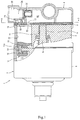
Fig. 1 is a side cross-sectional view in which a portion of a piston-type compressor as an example of a compressor according to the present invention is cut out. -
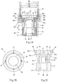
Fig. 2 includes views of a check valve assembly, in which (a) is a cross-sectional view thereof, (b) is a plan view thereof, and (c) is a side view thereof. -
Fig. 3 includes cross-sectional views of the check valve assembly, in which (a) is a view of a state at the time when a flow rate is high, (b) is a view of a state at the time when the flow rate is low, and (c) is a view of a state where a pressure of a suction chamber is higher than a pressure of an inlet port. -
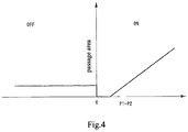
Fig. 4 is a characteristic graph that indicates a change in an opening amount (a passage area) of a suction passage extending from the inlet port to the suction chamber in the case where the check valve assembly of the present invention is used. -
Fig. 5(a) is a cross-sectional view of a conventional opening amount control valve, andFig. 5(b) is a characteristic graph that indicates a change in an opening amount (a passage area) of a suction passage extending from an inlet port to a suction chamber in the case where the conventional opening amount control valve is used. - A description will hereinafter be made on a case where a piston-type compressor is used as a compressor according to the present invention with reference to the accompanying drawings.
-
Fig. 1 illustrates a piston-type compressor 1 that serves as a part of a refrigeration circuit with a condenser, an expansion valve, and an evaporator, which are not illustrated. This piston-type compressor 1 is configured to have: acylinder block 2; acylinder head 4 that is assembled to a rear side of thiscylinder block 2 via a valve plate 3; and afront housing 6 that is assembled to cover a front side of thecylinder block 2 and defines a crankchamber 5 on the front side of thecylinder block 2. Thesefront housing 6,cylinder block 2, valve plate 3, andcylinder head 4 are fastened in an axial direction by unillustrated fastening bolts to constitute a compressor housing 7. - A
driveshaft 8 that is disposed in thecrank chamber 5 is held in a freely rotatable manner by thefront housing 6 and thecylinder block 2 via a bearing 9 (only the cylinder block side thereof is illustrated). Thisdriveshaft 8 is projected from thefront housing 6 and is connected to an unillustrated travel engine via a belt and a pulley so as to rotate when power of the travel engine is transmitted. - The
cylinder block 2 is formed with: a bearinghole 11 in which thebearing 9 is housed; and plural cylinder bores 12 that are disposed at equally-spaced intervals on a circumference centered on thisbearing hole 11. Asingle head piston 13 is inserted in each of the cylinder bores 12 in a manner to be reciprocally slidable. - In the
crank chamber 5, aswash plate 14 that rotates synchronously with thedriveshaft 8 is provided on the driveshaft. Anengagement section 13a of thesingle head piston 13 is firmly attached to a peripheral edge portion of thisswash plate 14 via a pair ofshoes 15 provided longitudinally. - Accordingly, when the
driveshaft 8 rotates, theswash plate 14 also rotates in conjunction with this. This rotary motion of theswash plate 14 is converted to linear reciprocating motion of thesingle head piston 13 via theshoes 15, and a volume of acompression chamber 16 formed between thesingle head piston 13 and the valve plate 3 in each of the cylinder bores 12 is thereby changed. - The valve plate 3 is formed with a suction hole 17 and a
discharge hole 18 that correspond to each of the cylinder bores 12. In addition, asuction chamber 20 and adischarge chamber 21 are defined in thecylinder head 4. Thesuction chamber 20 houses a working fluid to be supplied to thecompression chamber 16, and thedischarge chamber 21 houses the working fluid that is discharged from thecompression chamber 16. In this example, thesuction chamber 20 is formed in a central portion of thecylinder head 4, and thedischarge chamber 21 is annularly formed around thesuction chamber 20. - The
suction chamber 20 communicates with a low-pressure side of an external refrigerant circuit (an outlet side of the evaporator) via aninlet port 22 that radially extends in a manner to penetrate theannular discharge chamber 21. Thedischarge chamber 21 communicates with an unillustrated discharge port that is connected to a high-pressure side of the external refrigerant circuit (an inlet side of the condenser). In addition, thesuction chamber 20 can communicate with thecompression chamber 16 via the suction hole 17 that is opened/closed by asuction valve 23, and thedischarge chamber 21 can communicate with thecompression chamber 16 via thedischarge hole 18 that is opened/closed by adischarge valve 24. - Thus, in a suction stroke, the refrigerant is suctioned into the
compression chamber 16 from thesuction chamber 20 via the suction hole 17, which is opened/closed by thesuction valve 23, and, in a compression stroke, the compressed refrigerant is discharged from thecompression chamber 16 to thedischarge chamber 21 via thedischarge hole 18, which is opened/closed by thedischarge valve 24. - In such a compressor, on a downstream side of the
inlet port 22, that is, in asuction passage 25 that leads to thesuction chamber 20 from theinlet port 22, acheck valve assembly 30 is provided to vary an opening amount of thisintake passage 25. -
Fig. 2 shows schematic configuration diagrams of thecheck valve assembly 30. Thischeck valve assembly 30 is configured to have: avalve housing 31; and avalve body 41 and aspring 51 as an urging member that are housed in thisvalve housing 31. - The
valve housing 31 has a cylindrical shape in which a columnar valvebody housing space 32 is formed, and is loosely fitted to an inner wall of thesuction passage 25, which leads to thesuction chamber 20 from theinlet port 22, in such a manner that axial movement thereof is allowed. - More specifically, the
valve housing 31 is formed to have: a cylindricalperipheral wall 33; avalve seat section 34 that is provided at an upstream end of thisperipheral wall 33; abottom wall 35 that is provided at a downstream end of theperipheral wall 33; and an annular fittedsection 36 that is projected radially outward from a peripheral edge of the valve seat section 34 (a peripheral edge of an upstream end of thevalve housing 31 in the axial direction) . In addition, an annular groove (a holding section) 26 is formed on the inner wall of thesuction passage 25, which leads to thesuction chamber 20 from theinlet port 22 of the compressor housing 7 (the cylinder block 2), an axial dimension of thisannular groove 26 is set to be larger than an axial dimension of the fittedsection 36, and the fittedsection 36 is fitted in thisannular groove 26 in a manner to allow axial movement thereof. - The fitted
section 36 is constructed of: ashoulder 36a that extends radially outward from an outer circumference of the valve body (in this example, a peripheral edge of the valve seat section on the upstream side) ; and alocking wall 36b that continues from thisshoulder 36a and extends toward the upstream side, and can be deformed elastically by forming thislocking wall 36b such that a diameter thereof is gradually increased toward the upstream side. - The
suction passage 25 is formed such that a diameter R1 thereof on the upstream side of theannular groove 26 is almost equal to or larger than a diameter R2 of theshoulder 36a and is smaller than a tip diameter R3 of the lockingwall 36b. In addition, thesuction passage 25 is formed such that a diameter R4 thereof on the downstream side of theannular groove 26 is smaller than the diameter R2 of theshoulder 36a. Accordingly, anannular seat surface 26a on which theshoulder 36a of the fittedsection 36 can be seated is formed on the suction chamber side of theannular groove 26, and astopper surface 26b onto which a tip of the locking wall of the fittedsection 36 can be locked is formed on the inlet port side of theannular groove 26. - In this example, the fitted
section 36 is illustrated as an integrated member with thevalve seat section 34, theperipheral wall 33, and thebottom wall 35. However, the fittedsection 36 and theperipheral wall 33 may be formed integrally, and thevalve seat section 34 as a separate member may be attached thereto. Alternatively, the fittedsection 36 and thevalve seat section 34 may be formed integrally, and theperipheral wall 33 as a separate member may be attached thereto. - In addition, the fitted
section 36 may be formed of an elastic material such as rubber or may be formed of a synthetic resin. - In the
locking wall 36b of this fittedsection 36, plural communication holes (communication sections) 37, each of which communicates between the outside and the inside thereof, are formed circumferentially at equally-spaced intervals (for example, at every 90 degrees). - In the
valve housing 31 that has been described so far, aninflow port 38 that communicates between theinlet port 22 and the valvebody housing space 32 is formed in thevalve seat section 34, and theperipheral wall 33 is formed withplural outflow ports 39, each of which communicates between thesuction chamber 20 and the valvebody housing space 32, are formed circumferentially at equally-spaced intervals (for example, at every 90 degrees) in theperipheral wall 33. Furthermore, thebottom wall 35 of thevalve housing 31 is formed with an equalizingport 40, and the equalizingport 40 makes the rear of thevalve body 41, which is housed in the valvebody housing space 32 and will be described below, match a suction chamber pressure. - The
valve body 41 is housed in the valvebody housing space 32 of thevalve housing 31 in an axially movable manner, and is constructed of a hollow cylindrical piston, in which atop wall 42 and aperipheral wall 43 formed continuously from a peripheral edge of thistop wall 42 are integrally formed, and a bottom of which is eliminated. Thevalve body 41 is formed such that an outer diameter thereof is almost equal to an inner diameter of the valvebody housing space 32, and an outer peripheral surface of theperipheral wall 43 slidingly contacts an inner peripheral surface of the valvebody housing space 32 with specified clearance being interposed therebetween. In addition, axial length of thevalve body 41 is not particularly limited. However, thevalve body 41 is set to have such length that, in a state where thetop wall 42 of thevalve body 41 abuts a peripheral edge of theinflow port 38 in thevalve seat section 34 of the valve casing 31 from the inside, theoutflow ports 39 are closed by theperipheral wall 43 of thevalve body 41. - Each of the
outflow ports 39 is formed in a position away from thevalve seat section 34. Accordingly, even when thetop wall 42 of thevalve body 41 does not abut thevalve seat section 34 of thevalve housing 31, a communication state between theinflow port 38 and each of theoutflow ports 39 is blocked at a time point at which each of theoutflow ports 39 is closed by the outer peripheral surface of thevalve body 41. Thus, a lift section from a state where thevalve body 41 abuts an upstream end wall of thevalve housing 31 to a state where thevalve body 41 is lifted and closure of each of theoutflow ports 39 by the outer peripheral surface of thevalve body 41 is canceled corresponds to a closure section in which blockage of the communication state between theinflow port 38 and each of theoutflow ports 39 is maintained. - The
spring 51 is housed in thevalve body 41 in a manner to urge thevalve body 41 toward thevalve seat section 34 of thevalve housing 31. In this example, thespring 51 is elastically mounted between an inner surface of thetop wall 42 of thevalve body 41 and a peripheral edge of the equalizingport 40 in thebottom wall 35 of thevalve housing 31 by a specified setting force. - In the configuration that has been described so far, when the
check valve assembly 30 is attached to thecompressor 1, thevalve housing 31, which houses thevalve body 41, is inserted and pressed in thesuction passage 25 from theinlet port 22 with an opposite side of thevalve housing 31 from the fittedsection 36 being an insertion end. In this way, the fittedsection 36 is elastically deformed to be contracted inward. At a stage where the fittedsection 36 reaches theannular groove 26, theshoulder 36a abuts theseat surface 26a, the fittedsection 36 is restored by its own restoring force and expands in theannular groove 26, and the fittedsection 36 is loosely fitted to theannular groove 26 in such a manner that the axial movement thereof is allowed. - According to the
compressor 1 to which such acheck valve assembly 30 is attached, in the case where a large amount of the working fluid flows into thesuction chamber 20 from the inlet port 22 (flows through the suction passage 25), as illustrated inFig. 3(a) , thecheck valve assembly 30 is urged to the downstream side by a fluid pressure of the working fluid, and theshoulder 36a of thevalve housing 31 abuts theseat surface 26a, which is formed in a peripheral edge portion of the annular groove 26 (the holding section) on the suction chamber side, and thereby blocks the working fluid that flows on the outside of thevalve housing 31. Meanwhile, thevalve body 41, which is housed in thevalve housing 31, resists an urging force of thespring 51 by the fluid flowing from theinlet port 22 and moves in a direction to increase the communication state between theinflow port 38 and each of theoutflow ports 39. Then, the working fluid, which flows from theinlet port 22, flows through thevalve housing 31 and is suctioned into thesuction chamber 20. - Even in the case where a small amount of the working fluid flows into the
suction chamber 20 from theinlet port 22, as illustrated inFig. 3(b) , thecheck valve assembly 30 is urged to the downstream side by the fluid pressure of the working fluid, and theshoulder 36a of thevalve housing 31 abuts theseat surface 26a and thereby blocks the working fluid that flows on the outside of thevalve housing 31. However, since a flow rate of the working fluid is low, thevalve body 41, which is housed in thevalve housing 31, moves in a direction to reduce the communication state between theinflow port 38 and each of theoutflow ports 39 by the urging force of thespring 51. Accordingly, the working fluid, which flows from theinlet port 22, flows through thevalve housing 31 and is suctioned into thesuction chamber 20. However, since the opening amount of thesuction passage 25 is small, low-pressure pulsations that are generated at the time when the flow rate is low are unlikely to be transmitted from thesuction chamber 20 to theinlet port 22. Thus, the transmission of the low-pressure pulsations to an external cooling circuit is suppressed, and generation of abnormal noise can be avoided. - In particular, also in the case where the flow rate is extremely low (in the case where a difference between a primary-side pressure and a secondary-side pressure hardly exists), due to absence of a communication hole in the
top wall 42 of thevalve body 41, the working fluid, which flows from theinlet port 22, is suctioned into thesuction chamber 20 only through each of theoutflow ports 39, an opening amount of which is reduced in accordance with balance between the slightly generated pressure difference and the urging force of thespring 51. Accordingly, the transmission of the low-pressure pulsations to the external refrigerant circuit can reliably be inhibited, and the generation of the abnormal noise can reliably be suppressed. - In the case where the
compressor 1 is stopped and a pressure P2 of thesuction chamber 20 on the inside of the compressor becomes higher than a pressure P1 on a low-pressure piping side outside of the compressor with respect to the operation during activation of the compressor that has been described so far, as illustrated inFig. 3(c) , thevalve body 41 moves to the upstream side by the urging force of thespring 51 and the pressure P2 of thesuction chamber 20, is seated on thevalve seat section 34, and thereby blocks the communication state between theinflow port 38 and each of theoutflow ports 39. That is, the passage on the inside of thecheck valve assembly 30 is closed. However, in the case where such a pressure P2 of thesuction chamber 20 is higher than the pressure P1 on the low-pressure piping side outside of the compressor, the entirecheck valve assembly 30 also moves to the upstream side by the pressure of thesuction chamber 20, and the fittedsection 36 separates from theseat surface 26a (the peripheral edge portion of theannular groove 26 on the suction chamber side) and abuts a peripheral edge portion (thestopper surface 26b) of theannular groove 26 on the inlet port side. Accordingly, the working fluid in thesuction chamber 20 is released to theinlet port 22 via a portion between theshoulder 36a of thevalve housing 31 and theseat surface 26a, the outside of the fittedsection 36, and the communication holes 37 (the flow of the working fluid is allowed on the outside of the internal passage of the check valve assembly 30), and the pressure of the suction chamber 10 and the pressure of theinlet port 22 can thereby be balanced. Thus, a change in the opening amount of the suction passage 25 (an opening area) that includes thecheck valve assembly 30 of the present invention has a characteristic as illustrated inFig. 4 . - Therefore, such inconvenience that the pressure of the
suction chamber 20 is maintained in a high state during a stop of thecompressor 1 no longer exists, and such inconvenience that startability of thecompressor 1 is degraded due to a delay in opening of thevalve body 41 can be avoided. - In the above-described configuration, each of the communication sections provided in the fitted
section 36 is constructed of thecommunication hole 37. However, each of the communication sections may be configured by forming a slit on an outer peripheral surface of the fittedsection 36. - In addition, in the configuration described so far, the piston-type compressor is exemplified. However, the present invention can also be applied to another type of the compressor as long as intake pulsations are generated in the compressor.
-
- 1:
- Piston-type compressor
- 2:
- Cylinder block
- 3:
- Valve plate
- 4:
- Cylinder head
- 12:
- Cylinder bore
- 13:
- Piston
- 16:
- Compression chamber
- 17:
- Suction hole
- 20:
- Suction chamber
- 22:
- Inlet port
- 23:
- Suction valve
- 26:
- Annular groove
- 26a:
- Seat surface
- 30:
- Check valve assembly
- 31:
- Valve housing
- 32:
- Valve body housing space
- 36:
- Fitted section
- 37:
- Communication hole
- 38:
- Inflow port
- 39:
- Outflow port
- 41:
- Valve body
- 51:
- Spring
Claims (4)
- A compressor (1) used in a refrigeration circuit at least including a condenser, an expander, an evaporator, the compressor comprising:an inlet port (22) connected to a low-pressure side of this refrigeration circuit;a suction chamber (20) that houses a working fluid delivered from the inlet port (22);a compression mechanism that compresses the working fluid suctioned from the suction chamber (20); anda suction passage (25) that connects the inlet port (22) and the suction chamber (25), characterized in thata check valve assembly (30) that only allows a flow of the working fluid in a direction from the inlet port (22) to the suction chamber (20) is disposed on the suction passage (25), andpressure equalizing means that allows discharge of the working fluid from the suction chamber (20) to the inlet port (22) only when a pressure of the suction chamber (20) is higher than a pressure of the inlet port (22) is formed on the outside of an internal passage of the check valve assembly (30).
- The compressor (1) according to claim 1, wherein
the check valve assembly (30) includes:a valve housing (31) having a housing space (32) therein, and including an inflow port (38) communicating between the inlet port (22) and the housing space (32), and an outflow port (39) communicating between the suction chamber (20) and the housing space (32);a valve body (41) that is housed in the housing space (32) and moves within the housing space (32) on the basis of a pressure difference across the valve body (41) so as to regulate an opening amount of the outflow port (39); andan urging member (51) that urges the valve body (41) in a direction to reduce the opening amount of the outflow port (39) and close the inflow port (38). - The compressor according to claim 2, wherein
the valve housing (31) of the check valve assembly (30) has a fitted section (36) that is loosely fitted to a holding section (26) formed in the suction passage (25) in such a manner that axial movement thereof is allowed, and
the pressure equalizing means is formed by blocking the flow of the working fluid on the outside of the valve housing (31) in the case where the fitted section (36) abuts an edge portion (26a) of the holding section (26) on the suction chamber side and by allowing the flow of the working fluid on the outside of the valve housing (31) in the case where the fitted section (36) separates from the edge portion (26a) of the holding section (26) on the suction chamber side. - The compressor (1) according to claim 2 or 3, wherein
the valve housing (31) has a fitted section (36) expanding in a radial direction which is loosely fitted to an annular groove (26) formed on an inner peripheral wall of the suction passage (25),
a seat surface (26a) on which the fitted section (36) is seated is formed on the suction chamber side of the annular groove (26), and
the fitted section (36) is provided with a communication section (37) that communicates between the outside and the inside thereof.
Applications Claiming Priority (2)
| Application Number | Priority Date | Filing Date | Title |
|---|---|---|---|
| JP2015255660 | 2015-12-28 | ||
| PCT/JP2016/088364 WO2017115715A1 (en) | 2015-12-28 | 2016-12-22 | Compressor |
Publications (3)
| Publication Number | Publication Date |
|---|---|
| EP3415756A1 true EP3415756A1 (en) | 2018-12-19 |
| EP3415756A4 EP3415756A4 (en) | 2019-10-09 |
| EP3415756B1 EP3415756B1 (en) | 2020-10-07 |
Family
ID=59225040
Family Applications (1)
| Application Number | Title | Priority Date | Filing Date |
|---|---|---|---|
| EP16881690.8A Active EP3415756B1 (en) | 2015-12-28 | 2016-12-22 | Compressor |
Country Status (3)
| Country | Link |
|---|---|
| EP (1) | EP3415756B1 (en) |
| JP (1) | JP6857946B2 (en) |
| WO (1) | WO2017115715A1 (en) |
Cited By (1)
| Publication number | Priority date | Publication date | Assignee | Title |
|---|---|---|---|---|
| CN110748477A (en) * | 2019-11-27 | 2020-02-04 | 湖北文理学院 | Method and system for realizing stepless regulation of air quantity of compressor |
Families Citing this family (1)
| Publication number | Priority date | Publication date | Assignee | Title |
|---|---|---|---|---|
| JP7428286B1 (en) | 2023-03-20 | 2024-02-06 | いすゞ自動車株式会社 | valve device |
Family Cites Families (6)
| Publication number | Priority date | Publication date | Assignee | Title |
|---|---|---|---|---|
| JPH10159768A (en) * | 1996-12-03 | 1998-06-16 | Zexel Corp | Intake valve device for coolant compressor |
| JP3933369B2 (en) * | 2000-04-04 | 2007-06-20 | サンデン株式会社 | Piston type variable capacity compressor |
| JP4587778B2 (en) * | 2004-11-01 | 2010-11-24 | カルソニックカンセイ株式会社 | Discharge side structure, check valve used therefor, and compressor using them |
| JP4656044B2 (en) * | 2006-11-10 | 2011-03-23 | 株式会社豊田自動織機 | Compressor suction throttle valve |
| JP4640351B2 (en) * | 2007-02-16 | 2011-03-02 | 株式会社豊田自動織機 | Suction throttle valve for variable displacement compressor |
| JP2009102989A (en) * | 2007-10-19 | 2009-05-14 | Sanden Corp | Variable displacement compressor |
-
2016
- 2016-12-22 WO PCT/JP2016/088364 patent/WO2017115715A1/en not_active Ceased
- 2016-12-22 JP JP2017559163A patent/JP6857946B2/en active Active
- 2016-12-22 EP EP16881690.8A patent/EP3415756B1/en active Active
Cited By (1)
| Publication number | Priority date | Publication date | Assignee | Title |
|---|---|---|---|---|
| CN110748477A (en) * | 2019-11-27 | 2020-02-04 | 湖北文理学院 | Method and system for realizing stepless regulation of air quantity of compressor |
Also Published As
| Publication number | Publication date |
|---|---|
| WO2017115715A1 (en) | 2017-07-06 |
| EP3415756A4 (en) | 2019-10-09 |
| EP3415756B1 (en) | 2020-10-07 |
| JP6857946B2 (en) | 2021-04-14 |
| JPWO2017115715A1 (en) | 2018-10-18 |
Similar Documents
| Publication | Publication Date | Title |
|---|---|---|
| US11248502B2 (en) | Hydraulic oil control valve and valve timing adjustment device | |
| US10837431B2 (en) | Control valve for variable displacement compressor | |
| JP4700048B2 (en) | Capacity control valve | |
| JP5557901B2 (en) | Capacity control valve | |
| KR20180004044A (en) | Control valve for variable displacement compressor | |
| JP3933369B2 (en) | Piston type variable capacity compressor | |
| US9562524B2 (en) | Control valve for variable displacement compressor | |
| CN101155990B (en) | Capacity control valve | |
| CN107002648A (en) | Variable displacement compressor | |
| EP3415756B1 (en) | Compressor | |
| EP2963293B1 (en) | Control valve for variable displacement compressor | |
| JP4429931B2 (en) | Opening adjustment valve | |
| CN110073105B (en) | Valve structure of compressor | |
| JP2020034130A (en) | Compressor | |
| JP2020034129A (en) | Compressor | |
| JP2007327446A (en) | Opening adjusting valve and variable displacement compressor using this valve | |
| JP2016169700A (en) | Variable displacement compressor | |
| JP2007100814A (en) | Differential pressure regulating valve | |
| KR101370736B1 (en) | Compressor Control Valve | |
| WO2010143346A1 (en) | Variable capacity compressor | |
| JP2006207465A (en) | Variable displacement compressor | |
| JP6469994B2 (en) | Compressor | |
| KR20200055097A (en) | Relief valve | |
| JP2022074203A (en) | Opening adjustment valve of compressor | |
| JP2006118616A (en) | Hydraulic tensioner |
Legal Events
| Date | Code | Title | Description |
|---|---|---|---|
| STAA | Information on the status of an ep patent application or granted ep patent |
Free format text: STATUS: THE INTERNATIONAL PUBLICATION HAS BEEN MADE |
|
| PUAI | Public reference made under article 153(3) epc to a published international application that has entered the european phase |
Free format text: ORIGINAL CODE: 0009012 |
|
| STAA | Information on the status of an ep patent application or granted ep patent |
Free format text: STATUS: REQUEST FOR EXAMINATION WAS MADE |
|
| 17P | Request for examination filed |
Effective date: 20180727 |
|
| AK | Designated contracting states |
Kind code of ref document: A1 Designated state(s): AL AT BE BG CH CY CZ DE DK EE ES FI FR GB GR HR HU IE IS IT LI LT LU LV MC MK MT NL NO PL PT RO RS SE SI SK SM TR |
|
| AX | Request for extension of the european patent |
Extension state: BA ME |
|
| DAV | Request for validation of the european patent (deleted) | ||
| DAX | Request for extension of the european patent (deleted) | ||
| A4 | Supplementary search report drawn up and despatched |
Effective date: 20190911 |
|
| RIC1 | Information provided on ipc code assigned before grant |
Ipc: F04B 39/08 20060101ALI20190905BHEP Ipc: F04B 49/22 20060101ALI20190905BHEP Ipc: F04B 39/00 20060101AFI20190905BHEP Ipc: F04B 39/10 20060101ALI20190905BHEP |
|
| GRAP | Despatch of communication of intention to grant a patent |
Free format text: ORIGINAL CODE: EPIDOSNIGR1 |
|
| STAA | Information on the status of an ep patent application or granted ep patent |
Free format text: STATUS: GRANT OF PATENT IS INTENDED |
|
| RIC1 | Information provided on ipc code assigned before grant |
Ipc: F04B 39/00 20060101AFI20200508BHEP Ipc: F04B 39/10 20060101ALI20200508BHEP Ipc: F04B 49/22 20060101ALI20200508BHEP Ipc: F04B 39/08 20060101ALI20200508BHEP |
|
| INTG | Intention to grant announced |
Effective date: 20200528 |
|
| GRAS | Grant fee paid |
Free format text: ORIGINAL CODE: EPIDOSNIGR3 |
|
| GRAA | (expected) grant |
Free format text: ORIGINAL CODE: 0009210 |
|
| STAA | Information on the status of an ep patent application or granted ep patent |
Free format text: STATUS: THE PATENT HAS BEEN GRANTED |
|
| AK | Designated contracting states |
Kind code of ref document: B1 Designated state(s): AL AT BE BG CH CY CZ DE DK EE ES FI FR GB GR HR HU IE IS IT LI LT LU LV MC MK MT NL NO PL PT RO RS SE SI SK SM TR |
|
| REG | Reference to a national code |
Ref country code: GB Ref legal event code: FG4D |
|
| REG | Reference to a national code |
Ref country code: AT Ref legal event code: REF Ref document number: 1321419 Country of ref document: AT Kind code of ref document: T Effective date: 20201015 Ref country code: CH Ref legal event code: EP |
|
| REG | Reference to a national code |
Ref country code: IE Ref legal event code: FG4D |
|
| REG | Reference to a national code |
Ref country code: DE Ref legal event code: R096 Ref document number: 602016045622 Country of ref document: DE |
|
| REG | Reference to a national code |
Ref country code: NL Ref legal event code: MP Effective date: 20201007 |
|
| REG | Reference to a national code |
Ref country code: AT Ref legal event code: MK05 Ref document number: 1321419 Country of ref document: AT Kind code of ref document: T Effective date: 20201007 |
|
| PG25 | Lapsed in a contracting state [announced via postgrant information from national office to epo] |
Ref country code: GR Free format text: LAPSE BECAUSE OF FAILURE TO SUBMIT A TRANSLATION OF THE DESCRIPTION OR TO PAY THE FEE WITHIN THE PRESCRIBED TIME-LIMIT Effective date: 20210108 Ref country code: FI Free format text: LAPSE BECAUSE OF FAILURE TO SUBMIT A TRANSLATION OF THE DESCRIPTION OR TO PAY THE FEE WITHIN THE PRESCRIBED TIME-LIMIT Effective date: 20201007 Ref country code: PT Free format text: LAPSE BECAUSE OF FAILURE TO SUBMIT A TRANSLATION OF THE DESCRIPTION OR TO PAY THE FEE WITHIN THE PRESCRIBED TIME-LIMIT Effective date: 20210208 Ref country code: RS Free format text: LAPSE BECAUSE OF FAILURE TO SUBMIT A TRANSLATION OF THE DESCRIPTION OR TO PAY THE FEE WITHIN THE PRESCRIBED TIME-LIMIT Effective date: 20201007 Ref country code: NO Free format text: LAPSE BECAUSE OF FAILURE TO SUBMIT A TRANSLATION OF THE DESCRIPTION OR TO PAY THE FEE WITHIN THE PRESCRIBED TIME-LIMIT Effective date: 20210107 |
|
| REG | Reference to a national code |
Ref country code: LT Ref legal event code: MG4D |
|
| PG25 | Lapsed in a contracting state [announced via postgrant information from national office to epo] |
Ref country code: SE Free format text: LAPSE BECAUSE OF FAILURE TO SUBMIT A TRANSLATION OF THE DESCRIPTION OR TO PAY THE FEE WITHIN THE PRESCRIBED TIME-LIMIT Effective date: 20201007 Ref country code: BG Free format text: LAPSE BECAUSE OF FAILURE TO SUBMIT A TRANSLATION OF THE DESCRIPTION OR TO PAY THE FEE WITHIN THE PRESCRIBED TIME-LIMIT Effective date: 20210107 Ref country code: PL Free format text: LAPSE BECAUSE OF FAILURE TO SUBMIT A TRANSLATION OF THE DESCRIPTION OR TO PAY THE FEE WITHIN THE PRESCRIBED TIME-LIMIT Effective date: 20201007 Ref country code: IS Free format text: LAPSE BECAUSE OF FAILURE TO SUBMIT A TRANSLATION OF THE DESCRIPTION OR TO PAY THE FEE WITHIN THE PRESCRIBED TIME-LIMIT Effective date: 20210207 Ref country code: LV Free format text: LAPSE BECAUSE OF FAILURE TO SUBMIT A TRANSLATION OF THE DESCRIPTION OR TO PAY THE FEE WITHIN THE PRESCRIBED TIME-LIMIT Effective date: 20201007 Ref country code: ES Free format text: LAPSE BECAUSE OF FAILURE TO SUBMIT A TRANSLATION OF THE DESCRIPTION OR TO PAY THE FEE WITHIN THE PRESCRIBED TIME-LIMIT Effective date: 20201007 Ref country code: AT Free format text: LAPSE BECAUSE OF FAILURE TO SUBMIT A TRANSLATION OF THE DESCRIPTION OR TO PAY THE FEE WITHIN THE PRESCRIBED TIME-LIMIT Effective date: 20201007 |
|
| PG25 | Lapsed in a contracting state [announced via postgrant information from national office to epo] |
Ref country code: HR Free format text: LAPSE BECAUSE OF FAILURE TO SUBMIT A TRANSLATION OF THE DESCRIPTION OR TO PAY THE FEE WITHIN THE PRESCRIBED TIME-LIMIT Effective date: 20201007 Ref country code: NL Free format text: LAPSE BECAUSE OF FAILURE TO SUBMIT A TRANSLATION OF THE DESCRIPTION OR TO PAY THE FEE WITHIN THE PRESCRIBED TIME-LIMIT Effective date: 20201007 |
|
| REG | Reference to a national code |
Ref country code: DE Ref legal event code: R097 Ref document number: 602016045622 Country of ref document: DE |
|
| PG25 | Lapsed in a contracting state [announced via postgrant information from national office to epo] |
Ref country code: RO Free format text: LAPSE BECAUSE OF FAILURE TO SUBMIT A TRANSLATION OF THE DESCRIPTION OR TO PAY THE FEE WITHIN THE PRESCRIBED TIME-LIMIT Effective date: 20201007 Ref country code: SK Free format text: LAPSE BECAUSE OF FAILURE TO SUBMIT A TRANSLATION OF THE DESCRIPTION OR TO PAY THE FEE WITHIN THE PRESCRIBED TIME-LIMIT Effective date: 20201007 Ref country code: EE Free format text: LAPSE BECAUSE OF FAILURE TO SUBMIT A TRANSLATION OF THE DESCRIPTION OR TO PAY THE FEE WITHIN THE PRESCRIBED TIME-LIMIT Effective date: 20201007 Ref country code: CZ Free format text: LAPSE BECAUSE OF FAILURE TO SUBMIT A TRANSLATION OF THE DESCRIPTION OR TO PAY THE FEE WITHIN THE PRESCRIBED TIME-LIMIT Effective date: 20201007 Ref country code: SM Free format text: LAPSE BECAUSE OF FAILURE TO SUBMIT A TRANSLATION OF THE DESCRIPTION OR TO PAY THE FEE WITHIN THE PRESCRIBED TIME-LIMIT Effective date: 20201007 Ref country code: LT Free format text: LAPSE BECAUSE OF FAILURE TO SUBMIT A TRANSLATION OF THE DESCRIPTION OR TO PAY THE FEE WITHIN THE PRESCRIBED TIME-LIMIT Effective date: 20201007 |
|
| REG | Reference to a national code |
Ref country code: CH Ref legal event code: PL |
|
| PLBE | No opposition filed within time limit |
Free format text: ORIGINAL CODE: 0009261 |
|
| STAA | Information on the status of an ep patent application or granted ep patent |
Free format text: STATUS: NO OPPOSITION FILED WITHIN TIME LIMIT |
|
| PG25 | Lapsed in a contracting state [announced via postgrant information from national office to epo] |
Ref country code: DK Free format text: LAPSE BECAUSE OF FAILURE TO SUBMIT A TRANSLATION OF THE DESCRIPTION OR TO PAY THE FEE WITHIN THE PRESCRIBED TIME-LIMIT Effective date: 20201007 Ref country code: MC Free format text: LAPSE BECAUSE OF FAILURE TO SUBMIT A TRANSLATION OF THE DESCRIPTION OR TO PAY THE FEE WITHIN THE PRESCRIBED TIME-LIMIT Effective date: 20201007 |
|
| REG | Reference to a national code |
Ref country code: BE Ref legal event code: MM Effective date: 20201231 |
|
| 26N | No opposition filed |
Effective date: 20210708 |
|
| GBPC | Gb: european patent ceased through non-payment of renewal fee |
Effective date: 20210107 |
|
| PG25 | Lapsed in a contracting state [announced via postgrant information from national office to epo] |
Ref country code: IT Free format text: LAPSE BECAUSE OF FAILURE TO SUBMIT A TRANSLATION OF THE DESCRIPTION OR TO PAY THE FEE WITHIN THE PRESCRIBED TIME-LIMIT Effective date: 20201007 Ref country code: LU Free format text: LAPSE BECAUSE OF NON-PAYMENT OF DUE FEES Effective date: 20201222 Ref country code: IE Free format text: LAPSE BECAUSE OF NON-PAYMENT OF DUE FEES Effective date: 20201222 Ref country code: AL Free format text: LAPSE BECAUSE OF FAILURE TO SUBMIT A TRANSLATION OF THE DESCRIPTION OR TO PAY THE FEE WITHIN THE PRESCRIBED TIME-LIMIT Effective date: 20201007 |
|
| PG25 | Lapsed in a contracting state [announced via postgrant information from national office to epo] |
Ref country code: CH Free format text: LAPSE BECAUSE OF NON-PAYMENT OF DUE FEES Effective date: 20201231 Ref country code: SI Free format text: LAPSE BECAUSE OF FAILURE TO SUBMIT A TRANSLATION OF THE DESCRIPTION OR TO PAY THE FEE WITHIN THE PRESCRIBED TIME-LIMIT Effective date: 20201007 Ref country code: LI Free format text: LAPSE BECAUSE OF NON-PAYMENT OF DUE FEES Effective date: 20201231 Ref country code: GB Free format text: LAPSE BECAUSE OF NON-PAYMENT OF DUE FEES Effective date: 20210107 |
|
| PG25 | Lapsed in a contracting state [announced via postgrant information from national office to epo] |
Ref country code: IS Free format text: LAPSE BECAUSE OF FAILURE TO SUBMIT A TRANSLATION OF THE DESCRIPTION OR TO PAY THE FEE WITHIN THE PRESCRIBED TIME-LIMIT Effective date: 20210207 Ref country code: TR Free format text: LAPSE BECAUSE OF FAILURE TO SUBMIT A TRANSLATION OF THE DESCRIPTION OR TO PAY THE FEE WITHIN THE PRESCRIBED TIME-LIMIT Effective date: 20201007 Ref country code: MT Free format text: LAPSE BECAUSE OF FAILURE TO SUBMIT A TRANSLATION OF THE DESCRIPTION OR TO PAY THE FEE WITHIN THE PRESCRIBED TIME-LIMIT Effective date: 20201007 Ref country code: CY Free format text: LAPSE BECAUSE OF FAILURE TO SUBMIT A TRANSLATION OF THE DESCRIPTION OR TO PAY THE FEE WITHIN THE PRESCRIBED TIME-LIMIT Effective date: 20201007 |
|
| PG25 | Lapsed in a contracting state [announced via postgrant information from national office to epo] |
Ref country code: MK Free format text: LAPSE BECAUSE OF FAILURE TO SUBMIT A TRANSLATION OF THE DESCRIPTION OR TO PAY THE FEE WITHIN THE PRESCRIBED TIME-LIMIT Effective date: 20201007 |
|
| PG25 | Lapsed in a contracting state [announced via postgrant information from national office to epo] |
Ref country code: BE Free format text: LAPSE BECAUSE OF NON-PAYMENT OF DUE FEES Effective date: 20201231 |
|
| PGFP | Annual fee paid to national office [announced via postgrant information from national office to epo] |
Ref country code: FR Payment date: 20251230 Year of fee payment: 10 |
|
| PGFP | Annual fee paid to national office [announced via postgrant information from national office to epo] |
Ref country code: DE Payment date: 20251231 Year of fee payment: 10 |