EP3415741A1 - Electric accelerator device and control system thereof - Google Patents
Electric accelerator device and control system thereof Download PDFInfo
- Publication number
- EP3415741A1 EP3415741A1 EP17738210.8A EP17738210A EP3415741A1 EP 3415741 A1 EP3415741 A1 EP 3415741A1 EP 17738210 A EP17738210 A EP 17738210A EP 3415741 A1 EP3415741 A1 EP 3415741A1
- Authority
- EP
- European Patent Office
- Prior art keywords
- throttle
- power unit
- controller
- rotation shaft
- choker
- Prior art date
- Legal status (The legal status is an assumption and is not a legal conclusion. Google has not performed a legal analysis and makes no representation as to the accuracy of the status listed.)
- Granted
Links
- 230000005540 biological transmission Effects 0.000 claims abstract description 29
- 239000003502 gasoline Substances 0.000 claims abstract description 17
- 239000000446 fuel Substances 0.000 abstract description 16
- 230000004044 response Effects 0.000 abstract description 3
- 238000010586 diagram Methods 0.000 description 7
- 238000002485 combustion reaction Methods 0.000 description 6
- 239000000203 mixture Substances 0.000 description 6
- 238000000034 method Methods 0.000 description 5
- 239000007789 gas Substances 0.000 description 4
- 230000008569 process Effects 0.000 description 3
- 230000009286 beneficial effect Effects 0.000 description 2
- 230000002457 bidirectional effect Effects 0.000 description 2
- 230000003247 decreasing effect Effects 0.000 description 2
- 239000002737 fuel gas Substances 0.000 description 2
- 239000002828 fuel tank Substances 0.000 description 2
- 230000002411 adverse Effects 0.000 description 1
- 230000007547 defect Effects 0.000 description 1
- 230000001419 dependent effect Effects 0.000 description 1
- 230000000694 effects Effects 0.000 description 1
- 229910001416 lithium ion Inorganic materials 0.000 description 1
- 230000004048 modification Effects 0.000 description 1
- 238000012986 modification Methods 0.000 description 1
- 230000009467 reduction Effects 0.000 description 1
Images


Classifications
-
- F—MECHANICAL ENGINEERING; LIGHTING; HEATING; WEAPONS; BLASTING
- F02—COMBUSTION ENGINES; HOT-GAS OR COMBUSTION-PRODUCT ENGINE PLANTS
- F02M—SUPPLYING COMBUSTION ENGINES IN GENERAL WITH COMBUSTIBLE MIXTURES OR CONSTITUENTS THEREOF
- F02M1/00—Carburettors with means for facilitating engine's starting or its idling below operational temperatures
- F02M1/08—Carburettors with means for facilitating engine's starting or its idling below operational temperatures the means to facilitate starting or idling becoming operative or inoperative automatically
- F02M1/10—Carburettors with means for facilitating engine's starting or its idling below operational temperatures the means to facilitate starting or idling becoming operative or inoperative automatically dependent on engine temperature, e.g. having thermostat
-
- F—MECHANICAL ENGINEERING; LIGHTING; HEATING; WEAPONS; BLASTING
- F02—COMBUSTION ENGINES; HOT-GAS OR COMBUSTION-PRODUCT ENGINE PLANTS
- F02D—CONTROLLING COMBUSTION ENGINES
- F02D11/00—Arrangements for, or adaptations to, non-automatic engine control initiation means, e.g. operator initiated
- F02D11/06—Arrangements for, or adaptations to, non-automatic engine control initiation means, e.g. operator initiated characterised by non-mechanical control linkages, e.g. fluid control linkages or by control linkages with power drive or assistance
- F02D11/10—Arrangements for, or adaptations to, non-automatic engine control initiation means, e.g. operator initiated characterised by non-mechanical control linkages, e.g. fluid control linkages or by control linkages with power drive or assistance of the electric type
-
- F—MECHANICAL ENGINEERING; LIGHTING; HEATING; WEAPONS; BLASTING
- F02—COMBUSTION ENGINES; HOT-GAS OR COMBUSTION-PRODUCT ENGINE PLANTS
- F02D—CONTROLLING COMBUSTION ENGINES
- F02D41/00—Electrical control of supply of combustible mixture or its constituents
- F02D41/02—Circuit arrangements for generating control signals
- F02D41/021—Introducing corrections for particular conditions exterior to the engine
-
- F—MECHANICAL ENGINEERING; LIGHTING; HEATING; WEAPONS; BLASTING
- F02—COMBUSTION ENGINES; HOT-GAS OR COMBUSTION-PRODUCT ENGINE PLANTS
- F02D—CONTROLLING COMBUSTION ENGINES
- F02D41/00—Electrical control of supply of combustible mixture or its constituents
- F02D41/02—Circuit arrangements for generating control signals
- F02D41/04—Introducing corrections for particular operating conditions
- F02D41/06—Introducing corrections for particular operating conditions for engine starting or warming up
- F02D41/062—Introducing corrections for particular operating conditions for engine starting or warming up for starting
- F02D41/064—Introducing corrections for particular operating conditions for engine starting or warming up for starting at cold start
-
- F—MECHANICAL ENGINEERING; LIGHTING; HEATING; WEAPONS; BLASTING
- F02—COMBUSTION ENGINES; HOT-GAS OR COMBUSTION-PRODUCT ENGINE PLANTS
- F02D—CONTROLLING COMBUSTION ENGINES
- F02D41/00—Electrical control of supply of combustible mixture or its constituents
- F02D41/02—Circuit arrangements for generating control signals
- F02D41/04—Introducing corrections for particular operating conditions
- F02D41/06—Introducing corrections for particular operating conditions for engine starting or warming up
- F02D41/062—Introducing corrections for particular operating conditions for engine starting or warming up for starting
- F02D41/065—Introducing corrections for particular operating conditions for engine starting or warming up for starting at hot start or restart
-
- F—MECHANICAL ENGINEERING; LIGHTING; HEATING; WEAPONS; BLASTING
- F02—COMBUSTION ENGINES; HOT-GAS OR COMBUSTION-PRODUCT ENGINE PLANTS
- F02D—CONTROLLING COMBUSTION ENGINES
- F02D41/00—Electrical control of supply of combustible mixture or its constituents
- F02D41/02—Circuit arrangements for generating control signals
- F02D41/04—Introducing corrections for particular operating conditions
- F02D41/06—Introducing corrections for particular operating conditions for engine starting or warming up
- F02D41/062—Introducing corrections for particular operating conditions for engine starting or warming up for starting
- F02D41/067—Introducing corrections for particular operating conditions for engine starting or warming up for starting with control of the choke
-
- F—MECHANICAL ENGINEERING; LIGHTING; HEATING; WEAPONS; BLASTING
- F02—COMBUSTION ENGINES; HOT-GAS OR COMBUSTION-PRODUCT ENGINE PLANTS
- F02D—CONTROLLING COMBUSTION ENGINES
- F02D9/00—Controlling engines by throttling air or fuel-and-air induction conduits or exhaust conduits
- F02D9/02—Controlling engines by throttling air or fuel-and-air induction conduits or exhaust conduits concerning induction conduits
-
- F—MECHANICAL ENGINEERING; LIGHTING; HEATING; WEAPONS; BLASTING
- F02—COMBUSTION ENGINES; HOT-GAS OR COMBUSTION-PRODUCT ENGINE PLANTS
- F02B—INTERNAL-COMBUSTION PISTON ENGINES; COMBUSTION ENGINES IN GENERAL
- F02B63/00—Adaptations of engines for driving pumps, hand-held tools or electric generators; Portable combinations of engines with engine-driven devices
- F02B63/02—Adaptations of engines for driving pumps, hand-held tools or electric generators; Portable combinations of engines with engine-driven devices for hand-held tools
-
- F—MECHANICAL ENGINEERING; LIGHTING; HEATING; WEAPONS; BLASTING
- F02—COMBUSTION ENGINES; HOT-GAS OR COMBUSTION-PRODUCT ENGINE PLANTS
- F02D—CONTROLLING COMBUSTION ENGINES
- F02D11/00—Arrangements for, or adaptations to, non-automatic engine control initiation means, e.g. operator initiated
- F02D11/06—Arrangements for, or adaptations to, non-automatic engine control initiation means, e.g. operator initiated characterised by non-mechanical control linkages, e.g. fluid control linkages or by control linkages with power drive or assistance
- F02D11/10—Arrangements for, or adaptations to, non-automatic engine control initiation means, e.g. operator initiated characterised by non-mechanical control linkages, e.g. fluid control linkages or by control linkages with power drive or assistance of the electric type
- F02D2011/101—Arrangements for, or adaptations to, non-automatic engine control initiation means, e.g. operator initiated characterised by non-mechanical control linkages, e.g. fluid control linkages or by control linkages with power drive or assistance of the electric type characterised by the means for actuating the throttles
- F02D2011/102—Arrangements for, or adaptations to, non-automatic engine control initiation means, e.g. operator initiated characterised by non-mechanical control linkages, e.g. fluid control linkages or by control linkages with power drive or assistance of the electric type characterised by the means for actuating the throttles at least one throttle being moved only by an electric actuator
-
- F—MECHANICAL ENGINEERING; LIGHTING; HEATING; WEAPONS; BLASTING
- F02—COMBUSTION ENGINES; HOT-GAS OR COMBUSTION-PRODUCT ENGINE PLANTS
- F02D—CONTROLLING COMBUSTION ENGINES
- F02D2400/00—Control systems adapted for specific engine types; Special features of engine control systems not otherwise provided for; Power supply, connectors or cabling for engine control systems
- F02D2400/06—Small engines with electronic control, e.g. for hand held tools
-
- F—MECHANICAL ENGINEERING; LIGHTING; HEATING; WEAPONS; BLASTING
- F02—COMBUSTION ENGINES; HOT-GAS OR COMBUSTION-PRODUCT ENGINE PLANTS
- F02D—CONTROLLING COMBUSTION ENGINES
- F02D9/00—Controlling engines by throttling air or fuel-and-air induction conduits or exhaust conduits
- F02D9/08—Throttle valves specially adapted therefor; Arrangements of such valves in conduits
- F02D9/10—Throttle valves specially adapted therefor; Arrangements of such valves in conduits having pivotally-mounted flaps
- F02D9/1065—Mechanical control linkage between an actuator and the flap, e.g. including levers, gears, springs, clutches, limit stops of the like
-
- F—MECHANICAL ENGINEERING; LIGHTING; HEATING; WEAPONS; BLASTING
- F02—COMBUSTION ENGINES; HOT-GAS OR COMBUSTION-PRODUCT ENGINE PLANTS
- F02M—SUPPLYING COMBUSTION ENGINES IN GENERAL WITH COMBUSTIBLE MIXTURES OR CONSTITUENTS THEREOF
- F02M1/00—Carburettors with means for facilitating engine's starting or its idling below operational temperatures
- F02M1/02—Carburettors with means for facilitating engine's starting or its idling below operational temperatures the means to facilitate starting or idling being chokes for enriching fuel-air mixture
Definitions
- the present invention relates to an electric throttle device and a controlling system thereof.
- a portable gasoline engine used for a garden tool has an intake system including an air filter, a choker, a carburetor, an intake tube, a throttle, and other parts, with its main function of using the carburetor to vaporize and mix air and fuel, in a certain proportion, into combustible gas which enters a combustion chamber through an intake channel.
- the air passes through the air filter and the choker into a throat of the carburetor, wherein the air filter functions to filter the air and the choker functions to adjust and control the flow of the air entering the carburetor.
- the carburetor is provided, at its throat, with a device for adjusting the flow of the fuel entering the throat.
- the portable gasoline engine When the portable gasoline engine is started, especially at a relatively low ambient temperature, it is required to increase the fuel concentration in the fuel-gas mixture introduced into the combustion chamber, in order to facilitate starting the gasoline engine. That is, on one hand, it is required to increase the flow of the fuel of the carburetor; and on the other hand, it is required to decrease the amount of the air introduced into the carburetor.
- it in order to decrease the amount of the intake air, it is a commonly used method for the operator to manually close the choker according to the temperature of the use environment, thus decreasing the amount of the intake air.
- the operator needs to make a decision according to the ambient temperature in order to manually operate to close the choker, and also needs to re-open the choker when the gasoline engine is normally working.
- the manual operation is quite complicated, with a certain skill requirement on the operator, which is adverse to the popularization and promotion of the product.
- the technical problem to be solved by the present invention is to provide an electric throttle device and a controlling system thereof, wherein the operation is simple and convenient, without requirement for skills and experiences on the operators, enabling better use experience for the users and facilitating popularization and promotion of the product.
- a first technical solution of the present invention is: an electric throttle device, used for a portable gasoline engine which includes a body, a cylinder provided in the body, and a carburetor provided at a side of the cylinder and with an intake channel;
- the electric throttle device includes a rotation shaft and a throttle mounted on the rotation shaft, the throttle working to open or close the intake channel;
- the electric throttle device further includes a power unit, a transmission unit in a transmission connection with the power unit, and a controller; wherein the transmission unit is matched with the rotation shaft, and the controller is provided with an circuit driving module for driving the power unit to control the opening or closing of the throttle.
- the transmission unit cooperates with an end of the rotation shaft via a throttle pull rod for movement, and the throttle and the rotation shaft are rotated coaxially.
- the transmission unit includes a rack, and a gear cooperating with the rack and connected to an output of the power unit.
- the power unit is an electric motor, or a combination of an electric motor and a gearbox, or in an electric-magnetic form, or in a pneumatic form.
- the electric motor is a DC or AC electric motor enabling bidirectional rotation.
- the electric throttle device further includes a temperature sensor connected with the controller, and a choker controlling device connected with the controller, wherein the choker controlling device includes a choker shaft and a choker mounted on the choker shaft, the choker working to open or close the intake channel and the choker shaft being parallel to the rotation shaft.
- the controller employs a hot-start mode and opens the choker when the ambient temperature is higher than a preset value, and employs a cold-start mode and closes the choker when the ambient temperature is lower than a preset value.
- the choker shaft is driven by another power unit, wherein the choker is located at an intake end of the intake channel while the throttle is located at an exhaust end of the intake channel.
- the electric throttle device further includes a rotation end and an unlocking end which are located at the two ends of the rotation shaft, respectively, wherein the rotation end is fixed to a throttle pull rod and the unlocking end cooperates with the choker controlling device for movement, and the throttle is opened to drive the choker to open.
- a second technical solution of the present invention is: an electric throttle controlling system, including a rotation shaft provided on a carburetor, and a throttle provided on the rotation shaft and used for opening or closing an intake channel of the carburetor;
- the electric throttle controlling system includes a power unit, a DC power source providing energy to the power unit, a transmission unit in a transmission connection with the power unit, a controller for controlling power output of the power unit, and a manipulator in wireless communication with the controller, wherein the controller is provided with an circuit driving module for driving the power unit and controlling the opening or closing of the throttle, and a wireless communication module for receiving a wireless signal from the manipulator.
- a third technical solution of the present invention is: an electric throttle controlling system, including a rotation shaft provided on a carburetor, and a throttle provided on the rotation shaft and used for opening or closing an intake channel of the carburetor;
- the electric throttle controlling system includes a power unit, a DC power source providing energy to the power unit, a transmission unit in a transmission connection with the power unit, a controller for controlling power output of the power unit, and a manipulator in wireless communication with the controller, wherein the controller is provided with an circuit driving module for driving the power unit and controlling the opening or closing of the throttle, the manipulator and the controller are separated from each other and are connected for controlling via a signal line to each other.
- the controller is used, by controlling the power unit (servo motor) and in cooperation with the temperature sensor, to control and adjust opening or closing of the choker, achieving the co-movement of the throttle and the choker, so as to control the flow of the air entering the carburetor. Further, the controller is used, by controlling the servo motor, to control and adjust the fuel flow adjusting device on the carburetor, so as to adjusting the flow of the fuel of the carburetor. Therefore, free adjustment of the mixture ratio of the fuel to the air in various situations is enabled, while it cannot be freely adjusted in the prior art. With free adjustment, it is advantageous to adjust the fuel concentration as required. For example, in cold start, it is possible to increase the fuel concentration to facilitate starting of the gasoline engine.
- the throttle and the choker can be opened or closed automatically.
- the operation is simple and convenient, without requirement for skills and experiences on the operators. It provides a simple structure, high reliability, and sensitive response, thus enabling better use experience for the users and facilitating popularization and promotion of the product.
- a first embodiment of an electric throttle device is provided, used for a portable gasoline engine which includes a body 10 , a cylinder 12 provided in the body 10 , a piston 14 provided in the cylinder 12 , a crankshaft 16 linked with the piston 14 for co-movement, a fuel tank 20 provided on the body 10 , a carburetor 30 provided at a side of the cylinder 12 and with an intake channel 32 , a choker controlling device 40 provided on the carburetor 30 , an electric throttle controlling device 50 provided on the carburetor 30 ;
- the electric throttle device 50 includes a rotation shaft 52 and a throttle 58 mounted on the rotation shaft 52 , the throttle 58 working to open or close the intake channel 32 ;
- the electric throttle device 50 further includes a power unit 60 , a transmission unit in a transmission connection with the power unit 60 , and a controller; wherein the transmission unit is matched with the rotation shaft 52 , and the controller is provided with
- the transmission unit cooperates with an end of the rotation shaft 52 via a throttle pull rod 68 for movement, and the throttle 58 and the rotation shaft 52 are rotated coaxially.
- the transmission unit includes a rack 66 fixed to the throttle pull rod 68 , and a gear 64 cooperating with the rack 66 and connected to an output of the power unit 60.
- the transmission unit may directly cooperate with an end of the rotation shaft for movement, which is also possible to achieve the purpose of the present invention.
- the rack and gear transmission structure used in the transmission unit is simple, reliable, and low-cost. It is also possible to use a transmission manner with a band, a chain, a hinge, or a swing rod, to achieve the purpose of the present invention.
- the electric throttle device 50 further includes a temperature sensor connected with the controller, and a choker controlling device connected with the controller, wherein the choker controlling device includes a choker shaft and a choker mounted on the choker shaft, the choker working to open or close the intake channel 32 and the choker shaft being parallel to the rotation shaft.
- the controller employs a hot-start mode and opens the choker when the ambient temperature is higher than a preset value, and employs a cold-start mode and closes the choker when the ambient temperature is lower than a preset value.
- the choker shaft is driven by another power unit, wherein the choker is located at an intake end of the intake channel 32 while the throttle 58 is located at an exhaust end of the intake channel 32.
- the electric throttle device further includes a rotation end 54 and an unlocking end 56 which are located at the two ends of the rotation shaft 52 , respectively, wherein the rotation end 54 is fixed to the throttle pull rod 68 and the unlocking end 56 cooperates with the choker controlling device for movement.
- the throttle 58 is opened to drive the choker to open, thus achieving co-movement of the throttle 58 and the choker.
- the rotation end 54 is at least partially in a circular arc shape, and is provided with several fixing holes 59 arranged in an arc shape, wherein one of the fixing holes 59 is fixed to an end of the throttle pull rod 68 by snap-fitting.
- the power unit 60 is preferably an electric motor, or a combination of an electric motor and a gearbox, or in an electric-magnetic form, or in a pneumatic form.
- the electric motor is preferably a DC or AC electric motor enabling bidirectional rotation, and is also referred as servo motor. In the present embodiment, it is preferably a DC servo electric motor, enabling a compact structure, a large torque and a programmable controlling.
- the carburetor 30 is located at a side of the cylinder 12 and above the fuel tank 20.
- the carburetor 30 is connected, via a gas deliver channel, with the cylinder 12.
- the cylinder 12 is provided therein with a combustion chamber into which a mixture of fuel and gas is introduced for combustion.
- the throttle 58 is fixed on the rotation shaft 52 and can be rotated together with the rotation shaft 52 , and the rotation shaft 52 is mounted in the intake channel 32 inside the carburetor 30.
- the controller controls the power unit 60 to work and drives the gear 64 to rotate via the output shaft 62 , thus driving the rack 66 to move linearly, which in turn drives the throttle pull rod 68 to move linearly.
- the throttle pull rod 68 is connected with the rotation end 54
- the rotation end 54 drives the rotation shaft 52 , located at its center, to rotate together, bringing the throttle 58 to the opening position.
- the unlocking end 56 opens the choker by co-movement to increase the amount of intake air, thus the gasoline engine comes into the high speed state, achieving the automatic controlling of the choker controlling device and the electric throttle device.
- a second embodiment of an electric throttle controlling system including a power source, a power source module connected with the power source and used for voltage reduction, a controller connected with the power source module and controlling the running of the power unit, and a temperature sensor connected with the controller, a choker controlling unit connected with the controller, a throttle controlling unit connected with the controller, an electric-starting controlling unit connected with the controller, a high voltage ignition unit connected with the controller, a speed feedback unit connected with the controller and with a Hall element, and a temperature sensor connected with the controller.
- the high voltage ignition unit includes an ignition coil, a spark plug, and other elements.
- the power source is preferably a removable rechargeable battery, more preferably a Li-ion battery, and also provides energy to the power unit.
- the controller is a PLC controller.
- the controller at least includes an circuit driving module connected with the electric motor, a temperature sensor module, and an angle module for controlling the rotation angle of the choker, wherein the controller is provided therein with a main chip circuit and its electric circuit structure is specifically detailed in figure 7 , the electric circuit inside the power source module is specifically detailed in figure 8 , the electric circuit structure of the high voltage ignition unit is specifically detailed in figure 9 , the electric circuit structure of the choker and the throttle controlling unit is specifically detailed in figure 10 , and the electric circuit structure of the electric-starting controlling unit is specifically detailed in figure 11 .
- the ambient temperature is detected by the temperature sensor.
- the concentration of the fuel in the fuel-gas mixture to be introduced into the combustion chamber is increased, that is, the amount of the air to be introduced into the carburetor is decreased, so as to automatically close the choker by the controller controlling the rotation of the electric motor.
- the choker and the throttle are re-opened automatically. The whole process is simple and convenient, enabling automatic setting of the starting state of the gasoline engine in various starting situations, reducing interference to the starting process of the gasoline engine from the operator who is starting it, and also alleviating the labor intensity of the operator.
Abstract
Description
- The present invention relates to an electric throttle device and a controlling system thereof.
- Nowadays, a portable gasoline engine used for a garden tool has an intake system including an air filter, a choker, a carburetor, an intake tube, a throttle, and other parts, with its main function of using the carburetor to vaporize and mix air and fuel, in a certain proportion, into combustible gas which enters a combustion chamber through an intake channel. In an intake system of the prior art, the air passes through the air filter and the choker into a throat of the carburetor, wherein the air filter functions to filter the air and the choker functions to adjust and control the flow of the air entering the carburetor. The carburetor is provided, at its throat, with a device for adjusting the flow of the fuel entering the throat. The air and the fuel come together at the throat, and due to the venturi tube effect, the fuel is vaporized and mixed with the air into the combustible gas mixture which then passes through the carburetor, the intake tube and the intake valve, and finally into the combustion chamber.
- When the portable gasoline engine is started, especially at a relatively low ambient temperature, it is required to increase the fuel concentration in the fuel-gas mixture introduced into the combustion chamber, in order to facilitate starting the gasoline engine. That is, on one hand, it is required to increase the flow of the fuel of the carburetor; and on the other hand, it is required to decrease the amount of the air introduced into the carburetor. However, in the prior art, in order to decrease the amount of the intake air, it is a commonly used method for the operator to manually close the choker according to the temperature of the use environment, thus decreasing the amount of the intake air. In such method, the operator needs to make a decision according to the ambient temperature in order to manually operate to close the choker, and also needs to re-open the choker when the gasoline engine is normally working. In the whole process, the manual operation is quite complicated, with a certain skill requirement on the operator, which is adverse to the popularization and promotion of the product.
- In addition, the user who is using the portable gasoline engine, after the gasoline engine is started, often forgets to open the choker and directly increases the throttle, resulting in stalling of the gasoline engine due to insufficient intake. Though the devices linking the throttle and the choker for co-movement have been developed by many companies in China and abroad, they have defects of complicated structure, poor reliability, insensitive response, etc.
- The technical problem to be solved by the present invention is to provide an electric throttle device and a controlling system thereof, wherein the operation is simple and convenient, without requirement for skills and experiences on the operators, enabling better use experience for the users and facilitating popularization and promotion of the product.
- A first technical solution of the present invention is: an electric throttle device, used for a portable gasoline engine which includes a body, a cylinder provided in the body, and a carburetor provided at a side of the cylinder and with an intake channel; the electric throttle device includes a rotation shaft and a throttle mounted on the rotation shaft, the throttle working to open or close the intake channel; the electric throttle device further includes a power unit, a transmission unit in a transmission connection with the power unit, and a controller; wherein the transmission unit is matched with the rotation shaft, and the controller is provided with an circuit driving module for driving the power unit to control the opening or closing of the throttle.
- Based on the first technical solution, the following dependent technical solutions are further included.
- The transmission unit cooperates with an end of the rotation shaft via a throttle pull rod for movement, and the throttle and the rotation shaft are rotated coaxially.
- The transmission unit includes a rack, and a gear cooperating with the rack and connected to an output of the power unit.
- The power unit is an electric motor, or a combination of an electric motor and a gearbox, or in an electric-magnetic form, or in a pneumatic form.
- The electric motor is a DC or AC electric motor enabling bidirectional rotation.
- The electric throttle device further includes a temperature sensor connected with the controller, and a choker controlling device connected with the controller, wherein the choker controlling device includes a choker shaft and a choker mounted on the choker shaft, the choker working to open or close the intake channel and the choker shaft being parallel to the rotation shaft.
- The controller employs a hot-start mode and opens the choker when the ambient temperature is higher than a preset value, and employs a cold-start mode and closes the choker when the ambient temperature is lower than a preset value.
- The choker shaft is driven by another power unit, wherein the choker is located at an intake end of the intake channel while the throttle is located at an exhaust end of the intake channel.
- The electric throttle device further includes a rotation end and an unlocking end which are located at the two ends of the rotation shaft, respectively, wherein the rotation end is fixed to a throttle pull rod and the unlocking end cooperates with the choker controlling device for movement, and the throttle is opened to drive the choker to open.
- A second technical solution of the present invention is: an electric throttle controlling system, including a rotation shaft provided on a carburetor, and a throttle provided on the rotation shaft and used for opening or closing an intake channel of the carburetor; the electric throttle controlling system includes a power unit, a DC power source providing energy to the power unit, a transmission unit in a transmission connection with the power unit, a controller for controlling power output of the power unit, and a manipulator in wireless communication with the controller, wherein the controller is provided with an circuit driving module for driving the power unit and controlling the opening or closing of the throttle, and a wireless communication module for receiving a wireless signal from the manipulator.
- A third technical solution of the present invention is: an electric throttle controlling system, including a rotation shaft provided on a carburetor, and a throttle provided on the rotation shaft and used for opening or closing an intake channel of the carburetor; the electric throttle controlling system includes a power unit, a DC power source providing energy to the power unit, a transmission unit in a transmission connection with the power unit, a controller for controlling power output of the power unit, and a manipulator in wireless communication with the controller, wherein the controller is provided with an circuit driving module for driving the power unit and controlling the opening or closing of the throttle, the manipulator and the controller are separated from each other and are connected for controlling via a signal line to each other.
- In the present invention, the controller is used, by controlling the power unit (servo motor) and in cooperation with the temperature sensor, to control and adjust opening or closing of the choker, achieving the co-movement of the throttle and the choker, so as to control the flow of the air entering the carburetor. Further, the controller is used, by controlling the servo motor, to control and adjust the fuel flow adjusting device on the carburetor, so as to adjusting the flow of the fuel of the carburetor. Therefore, free adjustment of the mixture ratio of the fuel to the air in various situations is enabled, while it cannot be freely adjusted in the prior art. With free adjustment, it is advantageous to adjust the fuel concentration as required. For example, in cold start, it is possible to increase the fuel concentration to facilitate starting of the gasoline engine. Moreover, it is possible to freely set the fuel concentration under various load conditions to improve fuel efficiency and reduce emission. In addition, in the present invention, the throttle and the choker can be opened or closed automatically. The operation is simple and convenient, without requirement for skills and experiences on the operators. It provides a simple structure, high reliability, and sensitive response, thus enabling better use experience for the users and facilitating popularization and promotion of the product.
-
-
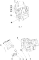
FIG. 1 is a section view of a first embodiment of the present invention; -
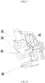
FIG. 2 is a partial structural diagram of the first embodiment of the present invention; -
FIG. 3 is an exploded view ofFIG. 2 ; -
FIG. 4 is a section view ofFIG. 2 , in an idling state; -
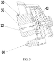
FIG. 5 is a section view ofFIG. 2 , in a high speed state; -
FIG. 6 is a modular diagram showing the functions of the electric circuit in a second embodiment of the present invention; -
FIG. 7 is an electric circuit diagram of the controller of the present invention; -
FIG. 8 is an electric circuit diagram of the power source module of the present invention; -
FIG. 9 is an electric circuit diagram of the high voltage ignition unit of the present invention; -
FIG. 10 is an electric circuit diagram of the choker and the throttle controlling unit of the present invention; and -
FIG. 11 is an electric circuit diagram of the electric-starting controlling unit of the present invention. - Embodiment(s): as shown in
figures 1-5 , in the present invention, a first embodiment of an electric throttle device is provided, used for a portable gasoline engine which includes abody 10, acylinder 12 provided in thebody 10, apiston 14 provided in thecylinder 12, acrankshaft 16 linked with thepiston 14 for co-movement, afuel tank 20 provided on thebody 10, acarburetor 30 provided at a side of thecylinder 12 and with anintake channel 32, achoker controlling device 40 provided on thecarburetor 30, an electricthrottle controlling device 50 provided on thecarburetor 30; theelectric throttle device 50 includes arotation shaft 52 and athrottle 58 mounted on therotation shaft 52, thethrottle 58 working to open or close theintake channel 32; theelectric throttle device 50 further includes apower unit 60, a transmission unit in a transmission connection with thepower unit 60, and a controller; wherein the transmission unit is matched with therotation shaft 52, and the controller is provided with an circuit driving module for driving the power unit to control the opening or closing of thethrottle 58. - The transmission unit cooperates with an end of the
rotation shaft 52 via athrottle pull rod 68 for movement, and thethrottle 58 and therotation shaft 52 are rotated coaxially. The transmission unit includes arack 66 fixed to thethrottle pull rod 68, and agear 64 cooperating with therack 66 and connected to an output of thepower unit 60. Likewise, the transmission unit may directly cooperate with an end of the rotation shaft for movement, which is also possible to achieve the purpose of the present invention. In the present invention, the rack and gear transmission structure used in the transmission unit is simple, reliable, and low-cost. It is also possible to use a transmission manner with a band, a chain, a hinge, or a swing rod, to achieve the purpose of the present invention. - Preferably, the
electric throttle device 50 further includes a temperature sensor connected with the controller, and a choker controlling device connected with the controller, wherein the choker controlling device includes a choker shaft and a choker mounted on the choker shaft, the choker working to open or close theintake channel 32 and the choker shaft being parallel to the rotation shaft. Preferably, the controller employs a hot-start mode and opens the choker when the ambient temperature is higher than a preset value, and employs a cold-start mode and closes the choker when the ambient temperature is lower than a preset value. Preferably, the choker shaft is driven by another power unit, wherein the choker is located at an intake end of theintake channel 32 while thethrottle 58 is located at an exhaust end of theintake channel 32. - Preferably, the electric throttle device further includes a
rotation end 54 and anunlocking end 56 which are located at the two ends of therotation shaft 52, respectively, wherein therotation end 54 is fixed to thethrottle pull rod 68 and theunlocking end 56 cooperates with the choker controlling device for movement. Thethrottle 58 is opened to drive the choker to open, thus achieving co-movement of thethrottle 58 and the choker. Therotation end 54 is at least partially in a circular arc shape, and is provided withseveral fixing holes 59 arranged in an arc shape, wherein one of thefixing holes 59 is fixed to an end of thethrottle pull rod 68 by snap-fitting. - The
power unit 60 is preferably an electric motor, or a combination of an electric motor and a gearbox, or in an electric-magnetic form, or in a pneumatic form. The electric motor is preferably a DC or AC electric motor enabling bidirectional rotation, and is also referred as servo motor. In the present embodiment, it is preferably a DC servo electric motor, enabling a compact structure, a large torque and a programmable controlling. - The
carburetor 30 is located at a side of thecylinder 12 and above thefuel tank 20. Thecarburetor 30 is connected, via a gas deliver channel, with thecylinder 12. Thecylinder 12 is provided therein with a combustion chamber into which a mixture of fuel and gas is introduced for combustion. - Therefore, in the present invention, the
throttle 58 is fixed on therotation shaft 52 and can be rotated together with therotation shaft 52, and therotation shaft 52 is mounted in theintake channel 32 inside thecarburetor 30. When the gasoline engine is in the idling state, thethrottle 58 is in the closed position, and the controller controls thepower unit 60 to work and drives thegear 64 to rotate via theoutput shaft 62, thus driving therack 66 to move linearly, which in turn drives thethrottle pull rod 68 to move linearly. As thethrottle pull rod 68 is connected with therotation end 54, the rotation end 54 drives therotation shaft 52, located at its center, to rotate together, bringing thethrottle 58 to the opening position. Then, the unlockingend 56 opens the choker by co-movement to increase the amount of intake air, thus the gasoline engine comes into the high speed state, achieving the automatic controlling of the choker controlling device and the electric throttle device. - As shown in
figures 6-11 , in the present invention, a second embodiment of an electric throttle controlling system is also provided, including a power source, a power source module connected with the power source and used for voltage reduction, a controller connected with the power source module and controlling the running of the power unit, and a temperature sensor connected with the controller, a choker controlling unit connected with the controller, a throttle controlling unit connected with the controller, an electric-starting controlling unit connected with the controller, a high voltage ignition unit connected with the controller, a speed feedback unit connected with the controller and with a Hall element, and a temperature sensor connected with the controller. The high voltage ignition unit includes an ignition coil, a spark plug, and other elements. In this case, the power source is preferably a removable rechargeable battery, more preferably a Li-ion battery, and also provides energy to the power unit. The controller is a PLC controller. The controller at least includes an circuit driving module connected with the electric motor, a temperature sensor module, and an angle module for controlling the rotation angle of the choker, wherein the controller is provided therein with a main chip circuit and its electric circuit structure is specifically detailed infigure 7 , the electric circuit inside the power source module is specifically detailed infigure 8 , the electric circuit structure of the high voltage ignition unit is specifically detailed infigure 9 , the electric circuit structure of the choker and the throttle controlling unit is specifically detailed infigure 10 , and the electric circuit structure of the electric-starting controlling unit is specifically detailed infigure 11 . Therefore, the ambient temperature is detected by the temperature sensor. Once the ambient temperature is lower than the preset value, in starting, the concentration of the fuel in the fuel-gas mixture to be introduced into the combustion chamber is increased, that is, the amount of the air to be introduced into the carburetor is decreased, so as to automatically close the choker by the controller controlling the rotation of the electric motor. When the gasoline engine is normally working, the choker and the throttle are re-opened automatically. The whole process is simple and convenient, enabling automatic setting of the starting state of the gasoline engine in various starting situations, reducing interference to the starting process of the gasoline engine from the operator who is starting it, and also alleviating the labor intensity of the operator. - Certainly, the above embodiments are provided only to explain the technical concepts and features of the present invention, with the purpose for enabling those skilled in the art to implement the present invention by understanding the contents thereof, rather than limiting the protection scope of the present invention thereto. Any equivalent alternative or modification made to the main technical solutions of the present invention based on the substantial spirit of the present invention will fall within the protection scope of the present invention.
Claims (7)
Applications Claiming Priority (2)
| Application Number | Priority Date | Filing Date | Title |
|---|---|---|---|
| CN201610024655.1A CN105484876A (en) | 2016-01-15 | 2016-01-15 | Electric accelerator device and control system thereof |
| PCT/CN2017/071177 WO2017121397A1 (en) | 2016-01-15 | 2017-01-13 | Electric accelerator device and control system thereof |
Publications (3)
| Publication Number | Publication Date |
|---|---|
| EP3415741A1 true EP3415741A1 (en) | 2018-12-19 |
| EP3415741A4 EP3415741A4 (en) | 2019-06-19 |
| EP3415741B1 EP3415741B1 (en) | 2022-03-23 |
Family
ID=55672107
Family Applications (1)
| Application Number | Title | Priority Date | Filing Date |
|---|---|---|---|
| EP17738210.8A Active EP3415741B1 (en) | 2016-01-15 | 2017-01-13 | Electric accelerator device and control system thereof |
Country Status (4)
| Country | Link |
|---|---|
| US (1) | US20190024612A1 (en) |
| EP (1) | EP3415741B1 (en) |
| CN (1) | CN105484876A (en) |
| WO (1) | WO2017121397A1 (en) |
Families Citing this family (6)
| Publication number | Priority date | Publication date | Assignee | Title |
|---|---|---|---|---|
| EP3404239B1 (en) * | 2016-01-15 | 2024-05-01 | Suzhou Cleva Precision Machinery & Technology Co., Ltd. | Garden tool |
| CN105484876A (en) * | 2016-01-15 | 2016-04-13 | 苏州科瓴精密机械科技有限公司 | Electric accelerator device and control system thereof |
| CN105508117A (en) | 2016-01-15 | 2016-04-20 | 苏州科瓴精密机械科技有限公司 | Portable gasoline tool and electronic ignition system thereof |
| CN106640384A (en) * | 2016-10-21 | 2017-05-10 | 江苏斯洛通电子科技有限公司 | Non-contact type hand and foot integrated waterproof electronic throttle |
| US10634111B2 (en) * | 2016-12-12 | 2020-04-28 | Kohler Co. | Ignition module for internal combustion engine with integrated communication device |
| CN110439711B (en) * | 2019-08-21 | 2020-08-14 | 成都纵横大鹏无人机科技有限公司 | Unmanned aerial vehicle engine control device and method |
Family Cites Families (17)
| Publication number | Priority date | Publication date | Assignee | Title |
|---|---|---|---|---|
| US4005690A (en) * | 1975-06-23 | 1977-02-01 | Honda Giken Kogyo Kabushiki Kaisha | Automatic choke valve apparatus in an internal combustion engine |
| US4177784A (en) * | 1976-12-21 | 1979-12-11 | Toyo Kogyo Co., Ltd. | Engine starting device |
| JPS59136550A (en) * | 1983-01-27 | 1984-08-06 | Honda Motor Co Ltd | Mixture adjusting device for carburettor |
| IT1221935B (en) * | 1987-07-02 | 1990-08-31 | Morini Franco Motori Spa | CONTROLLED POWER AND IGNITION EQUIPMENT FOR INTERNAL COMBUSTION ENGINES |
| DE4141533A1 (en) * | 1991-12-17 | 1993-06-24 | Guenther Lassnig | Portable current generating unit with LV current generator - has supply outputs accessible in given sequence so that motor power of drive motor increases with increasing number of supply outputs. |
| US5611312A (en) * | 1995-02-07 | 1997-03-18 | Walbro Corporation | Carburetor and method and apparatus for controlling air/fuel ratio of same |
| TWI297372B (en) * | 2004-03-03 | 2008-06-01 | Honda Motor Co Ltd | Device for controlling choke valve of carburetor |
| US7284522B2 (en) * | 2004-03-12 | 2007-10-23 | Honda Motor Co., Ltd. | Automatic choke |
| CN2797660Y (en) * | 2005-05-16 | 2006-07-19 | 西南师范大学 | Electric individual control type carburetor |
| US7171947B2 (en) * | 2005-05-27 | 2007-02-06 | Honda Motor Co., Ltd. | Electrically-actuated throttle device for general-purpose engine |
| CA2572595C (en) * | 2006-01-26 | 2011-03-29 | Honda Motor Co., Ltd | Engine-driven work machine |
| US8434444B2 (en) * | 2008-05-27 | 2013-05-07 | Briggs & Stratton Corporation | Engine with an automatic choke and method of operating an automatic choke for an engine |
| CN201747476U (en) * | 2010-09-03 | 2011-02-16 | 重庆宗申通用动力机械有限公司 | Automatic control device for carburetter choke |
| US9429107B2 (en) * | 2013-02-22 | 2016-08-30 | Briggs & Stratton Corporation | Solenoid autochoke for an engine |
| CN104791108A (en) * | 2015-05-05 | 2015-07-22 | 浙江中坚科技股份有限公司 | Automatic speed adjusting device for small-size two-stroke gasoline engine |
| CN205503286U (en) * | 2016-01-15 | 2016-08-24 | 苏州科瓴精密机械科技有限公司 | Electronic throttle device and control system thereof |
| CN105484876A (en) * | 2016-01-15 | 2016-04-13 | 苏州科瓴精密机械科技有限公司 | Electric accelerator device and control system thereof |
-
2016
- 2016-01-15 CN CN201610024655.1A patent/CN105484876A/en active Pending
-
2017
- 2017-01-13 US US16/070,357 patent/US20190024612A1/en not_active Abandoned
- 2017-01-13 EP EP17738210.8A patent/EP3415741B1/en active Active
- 2017-01-13 WO PCT/CN2017/071177 patent/WO2017121397A1/en active Application Filing
Also Published As
| Publication number | Publication date |
|---|---|
| WO2017121397A1 (en) | 2017-07-20 |
| CN105484876A (en) | 2016-04-13 |
| US20190024612A1 (en) | 2019-01-24 |
| EP3415741B1 (en) | 2022-03-23 |
| EP3415741A4 (en) | 2019-06-19 |
Similar Documents
| Publication | Publication Date | Title |
|---|---|---|
| EP3415741A1 (en) | Electric accelerator device and control system thereof | |
| CN103244334A (en) | Handheld work apparatus | |
| GB1275387A (en) | Method and apparatus for controlling the mixing ratio in dual-fuel engines for vehicles | |
| RU2629106C2 (en) | Start locking circuit in operating tool with internal combustion engine | |
| CN104295408B (en) | Method for running internal combustion engine | |
| US4787356A (en) | Carburetor arrangement for changing the ratio of the air/fuel mixture in handheld motor-driven apparatus | |
| CN205638728U (en) | Portable gasoline machine and automatic ventilation door control system thereof | |
| CN205503286U (en) | Electronic throttle device and control system thereof | |
| US20150047593A1 (en) | Method for starting a combustion engine having a starter apparatus | |
| CN105484899A (en) | Portable gasoline engine and automatic air door control system thereof | |
| CN101806253B (en) | Fuel-supply control device of dual-fuel engine | |
| CN203686255U (en) | Proportional valve for controlling proportion of air and fuel gas | |
| CN204984644U (en) | Small -size gasoline engine digital intelligent throttle control system | |
| CN101280727A (en) | Engine | |
| CN105464875B (en) | Portable gasoline tool | |
| WO2017121395A1 (en) | Garden tool | |
| CN202040059U (en) | Fuel air compressor with automatic control device | |
| US8770171B2 (en) | Combustion engine, diagnostic arrangement for a combustion engine and a method for setting a combustion engine | |
| CN203742832U (en) | Air-fuel ratio control device for carburetor | |
| US10774765B2 (en) | Method for starting a combustion engine having a starter apparatus | |
| CN206889118U (en) | A kind of control system of carburetor gasoline engine | |
| WO2009109103A1 (en) | A gas mixer of universal small combustion-gas engine for automatically controlling amount of combustion gas | |
| CN2786297Y (en) | Gasoline generator set carburetor | |
| CN104912693A (en) | Digital intelligent accelerator control system of small gasoline engine | |
| KR100309508B1 (en) | Apparatus for controlling fuel mixing and transferring fuel automatically in internal combustion engine |
Legal Events
| Date | Code | Title | Description |
|---|---|---|---|
| STAA | Information on the status of an ep patent application or granted ep patent |
Free format text: STATUS: THE INTERNATIONAL PUBLICATION HAS BEEN MADE |
|
| PUAI | Public reference made under article 153(3) epc to a published international application that has entered the european phase |
Free format text: ORIGINAL CODE: 0009012 |
|
| STAA | Information on the status of an ep patent application or granted ep patent |
Free format text: STATUS: REQUEST FOR EXAMINATION WAS MADE |
|
| 17P | Request for examination filed |
Effective date: 20180810 |
|
| AK | Designated contracting states |
Kind code of ref document: A1 Designated state(s): AL AT BE BG CH CY CZ DE DK EE ES FI FR GB GR HR HU IE IS IT LI LT LU LV MC MK MT NL NO PL PT RO RS SE SI SK SM TR |
|
| AX | Request for extension of the european patent |
Extension state: BA ME |
|
| RIC1 | Information provided on ipc code assigned before grant |
Ipc: F02D 41/06 20060101ALI20190211BHEP Ipc: F02M 1/10 20060101ALI20190211BHEP Ipc: F02D 11/10 20060101AFI20190211BHEP |
|
| STAA | Information on the status of an ep patent application or granted ep patent |
Free format text: STATUS: REQUEST FOR EXAMINATION WAS MADE |
|
| DAV | Request for validation of the european patent (deleted) | ||
| DAX | Request for extension of the european patent (deleted) | ||
| A4 | Supplementary search report drawn up and despatched |
Effective date: 20190517 |
|
| RIC1 | Information provided on ipc code assigned before grant |
Ipc: F02D 41/06 20060101ALI20190513BHEP Ipc: F02D 11/10 20060101AFI20190513BHEP Ipc: F02M 1/10 20060101ALI20190513BHEP |
|
| GRAP | Despatch of communication of intention to grant a patent |
Free format text: ORIGINAL CODE: EPIDOSNIGR1 |
|
| STAA | Information on the status of an ep patent application or granted ep patent |
Free format text: STATUS: GRANT OF PATENT IS INTENDED |
|
| INTG | Intention to grant announced |
Effective date: 20211111 |
|
| GRAS | Grant fee paid |
Free format text: ORIGINAL CODE: EPIDOSNIGR3 |
|
| GRAA | (expected) grant |
Free format text: ORIGINAL CODE: 0009210 |
|
| STAA | Information on the status of an ep patent application or granted ep patent |
Free format text: STATUS: THE PATENT HAS BEEN GRANTED |
|
| AK | Designated contracting states |
Kind code of ref document: B1 Designated state(s): AL AT BE BG CH CY CZ DE DK EE ES FI FR GB GR HR HU IE IS IT LI LT LU LV MC MK MT NL NO PL PT RO RS SE SI SK SM TR |
|
| REG | Reference to a national code |
Ref country code: GB Ref legal event code: FG4D |
|
| REG | Reference to a national code |
Ref country code: CH Ref legal event code: EP |
|
| REG | Reference to a national code |
Ref country code: IE Ref legal event code: FG4D |
|
| REG | Reference to a national code |
Ref country code: AT Ref legal event code: REF Ref document number: 1477583 Country of ref document: AT Kind code of ref document: T Effective date: 20220415 |
|
| REG | Reference to a national code |
Ref country code: DE Ref legal event code: R096 Ref document number: 602017054919 Country of ref document: DE |
|
| REG | Reference to a national code |
Ref country code: LT Ref legal event code: MG9D |
|
| REG | Reference to a national code |
Ref country code: NL Ref legal event code: MP Effective date: 20220323 |
|
| PG25 | Lapsed in a contracting state [announced via postgrant information from national office to epo] |
Ref country code: SE Free format text: LAPSE BECAUSE OF FAILURE TO SUBMIT A TRANSLATION OF THE DESCRIPTION OR TO PAY THE FEE WITHIN THE PRESCRIBED TIME-LIMIT Effective date: 20220323 Ref country code: RS Free format text: LAPSE BECAUSE OF FAILURE TO SUBMIT A TRANSLATION OF THE DESCRIPTION OR TO PAY THE FEE WITHIN THE PRESCRIBED TIME-LIMIT Effective date: 20220323 Ref country code: NO Free format text: LAPSE BECAUSE OF FAILURE TO SUBMIT A TRANSLATION OF THE DESCRIPTION OR TO PAY THE FEE WITHIN THE PRESCRIBED TIME-LIMIT Effective date: 20220623 Ref country code: LT Free format text: LAPSE BECAUSE OF FAILURE TO SUBMIT A TRANSLATION OF THE DESCRIPTION OR TO PAY THE FEE WITHIN THE PRESCRIBED TIME-LIMIT Effective date: 20220323 Ref country code: HR Free format text: LAPSE BECAUSE OF FAILURE TO SUBMIT A TRANSLATION OF THE DESCRIPTION OR TO PAY THE FEE WITHIN THE PRESCRIBED TIME-LIMIT Effective date: 20220323 Ref country code: BG Free format text: LAPSE BECAUSE OF FAILURE TO SUBMIT A TRANSLATION OF THE DESCRIPTION OR TO PAY THE FEE WITHIN THE PRESCRIBED TIME-LIMIT Effective date: 20220623 |
|
| REG | Reference to a national code |
Ref country code: AT Ref legal event code: MK05 Ref document number: 1477583 Country of ref document: AT Kind code of ref document: T Effective date: 20220323 |
|
| PG25 | Lapsed in a contracting state [announced via postgrant information from national office to epo] |
Ref country code: LV Free format text: LAPSE BECAUSE OF FAILURE TO SUBMIT A TRANSLATION OF THE DESCRIPTION OR TO PAY THE FEE WITHIN THE PRESCRIBED TIME-LIMIT Effective date: 20220323 Ref country code: GR Free format text: LAPSE BECAUSE OF FAILURE TO SUBMIT A TRANSLATION OF THE DESCRIPTION OR TO PAY THE FEE WITHIN THE PRESCRIBED TIME-LIMIT Effective date: 20220624 Ref country code: FI Free format text: LAPSE BECAUSE OF FAILURE TO SUBMIT A TRANSLATION OF THE DESCRIPTION OR TO PAY THE FEE WITHIN THE PRESCRIBED TIME-LIMIT Effective date: 20220323 |
|
| PG25 | Lapsed in a contracting state [announced via postgrant information from national office to epo] |
Ref country code: NL Free format text: LAPSE BECAUSE OF FAILURE TO SUBMIT A TRANSLATION OF THE DESCRIPTION OR TO PAY THE FEE WITHIN THE PRESCRIBED TIME-LIMIT Effective date: 20220323 |
|
| PG25 | Lapsed in a contracting state [announced via postgrant information from national office to epo] |
Ref country code: SM Free format text: LAPSE BECAUSE OF FAILURE TO SUBMIT A TRANSLATION OF THE DESCRIPTION OR TO PAY THE FEE WITHIN THE PRESCRIBED TIME-LIMIT Effective date: 20220323 Ref country code: SK Free format text: LAPSE BECAUSE OF FAILURE TO SUBMIT A TRANSLATION OF THE DESCRIPTION OR TO PAY THE FEE WITHIN THE PRESCRIBED TIME-LIMIT Effective date: 20220323 Ref country code: RO Free format text: LAPSE BECAUSE OF FAILURE TO SUBMIT A TRANSLATION OF THE DESCRIPTION OR TO PAY THE FEE WITHIN THE PRESCRIBED TIME-LIMIT Effective date: 20220323 Ref country code: PT Free format text: LAPSE BECAUSE OF FAILURE TO SUBMIT A TRANSLATION OF THE DESCRIPTION OR TO PAY THE FEE WITHIN THE PRESCRIBED TIME-LIMIT Effective date: 20220725 Ref country code: ES Free format text: LAPSE BECAUSE OF FAILURE TO SUBMIT A TRANSLATION OF THE DESCRIPTION OR TO PAY THE FEE WITHIN THE PRESCRIBED TIME-LIMIT Effective date: 20220323 Ref country code: EE Free format text: LAPSE BECAUSE OF FAILURE TO SUBMIT A TRANSLATION OF THE DESCRIPTION OR TO PAY THE FEE WITHIN THE PRESCRIBED TIME-LIMIT Effective date: 20220323 Ref country code: CZ Free format text: LAPSE BECAUSE OF FAILURE TO SUBMIT A TRANSLATION OF THE DESCRIPTION OR TO PAY THE FEE WITHIN THE PRESCRIBED TIME-LIMIT Effective date: 20220323 Ref country code: AT Free format text: LAPSE BECAUSE OF FAILURE TO SUBMIT A TRANSLATION OF THE DESCRIPTION OR TO PAY THE FEE WITHIN THE PRESCRIBED TIME-LIMIT Effective date: 20220323 |
|
| PG25 | Lapsed in a contracting state [announced via postgrant information from national office to epo] |
Ref country code: PL Free format text: LAPSE BECAUSE OF FAILURE TO SUBMIT A TRANSLATION OF THE DESCRIPTION OR TO PAY THE FEE WITHIN THE PRESCRIBED TIME-LIMIT Effective date: 20220323 Ref country code: IS Free format text: LAPSE BECAUSE OF FAILURE TO SUBMIT A TRANSLATION OF THE DESCRIPTION OR TO PAY THE FEE WITHIN THE PRESCRIBED TIME-LIMIT Effective date: 20220723 Ref country code: AL Free format text: LAPSE BECAUSE OF FAILURE TO SUBMIT A TRANSLATION OF THE DESCRIPTION OR TO PAY THE FEE WITHIN THE PRESCRIBED TIME-LIMIT Effective date: 20220323 |
|
| REG | Reference to a national code |
Ref country code: DE Ref legal event code: R097 Ref document number: 602017054919 Country of ref document: DE |
|
| PLBE | No opposition filed within time limit |
Free format text: ORIGINAL CODE: 0009261 |
|
| STAA | Information on the status of an ep patent application or granted ep patent |
Free format text: STATUS: NO OPPOSITION FILED WITHIN TIME LIMIT |
|
| PG25 | Lapsed in a contracting state [announced via postgrant information from national office to epo] |
Ref country code: DK Free format text: LAPSE BECAUSE OF FAILURE TO SUBMIT A TRANSLATION OF THE DESCRIPTION OR TO PAY THE FEE WITHIN THE PRESCRIBED TIME-LIMIT Effective date: 20220323 |
|
| 26N | No opposition filed |
Effective date: 20230102 |
|
| PGFP | Annual fee paid to national office [announced via postgrant information from national office to epo] |
Ref country code: FR Payment date: 20230125 Year of fee payment: 7 |
|
| PG25 | Lapsed in a contracting state [announced via postgrant information from national office to epo] |
Ref country code: SI Free format text: LAPSE BECAUSE OF FAILURE TO SUBMIT A TRANSLATION OF THE DESCRIPTION OR TO PAY THE FEE WITHIN THE PRESCRIBED TIME-LIMIT Effective date: 20220323 |
|
| PGFP | Annual fee paid to national office [announced via postgrant information from national office to epo] |
Ref country code: GB Payment date: 20230123 Year of fee payment: 7 Ref country code: DE Payment date: 20230112 Year of fee payment: 7 |
|
| PG25 | Lapsed in a contracting state [announced via postgrant information from national office to epo] |
Ref country code: IT Free format text: LAPSE BECAUSE OF FAILURE TO SUBMIT A TRANSLATION OF THE DESCRIPTION OR TO PAY THE FEE WITHIN THE PRESCRIBED TIME-LIMIT Effective date: 20220323 |
|
| REG | Reference to a national code |
Ref country code: CH Ref legal event code: PL |
|
| PG25 | Lapsed in a contracting state [announced via postgrant information from national office to epo] |
Ref country code: LU Free format text: LAPSE BECAUSE OF NON-PAYMENT OF DUE FEES Effective date: 20230113 |
|
| REG | Reference to a national code |
Ref country code: BE Ref legal event code: MM Effective date: 20230131 |
|
| PG25 | Lapsed in a contracting state [announced via postgrant information from national office to epo] |
Ref country code: LI Free format text: LAPSE BECAUSE OF NON-PAYMENT OF DUE FEES Effective date: 20230131 Ref country code: CH Free format text: LAPSE BECAUSE OF NON-PAYMENT OF DUE FEES Effective date: 20230131 |
|
| PG25 | Lapsed in a contracting state [announced via postgrant information from national office to epo] |
Ref country code: BE Free format text: LAPSE BECAUSE OF NON-PAYMENT OF DUE FEES Effective date: 20230131 |
|
| PG25 | Lapsed in a contracting state [announced via postgrant information from national office to epo] |
Ref country code: IE Free format text: LAPSE BECAUSE OF NON-PAYMENT OF DUE FEES Effective date: 20230113 |
|
| PGFP | Annual fee paid to national office [announced via postgrant information from national office to epo] |
Ref country code: DE Payment date: 20240115 Year of fee payment: 8 Ref country code: GB Payment date: 20240119 Year of fee payment: 8 |