EP3415458A1 - Device and method for automatic tensioning of a dispensing cable for a crane - Google Patents
Device and method for automatic tensioning of a dispensing cable for a crane Download PDFInfo
- Publication number
- EP3415458A1 EP3415458A1 EP18177015.7A EP18177015A EP3415458A1 EP 3415458 A1 EP3415458 A1 EP 3415458A1 EP 18177015 A EP18177015 A EP 18177015A EP 3415458 A1 EP3415458 A1 EP 3415458A1
- Authority
- EP
- European Patent Office
- Prior art keywords
- distributor
- stop
- carriage
- rotation
- cable
- Prior art date
- Legal status (The legal status is an assumption and is not a legal conclusion. Google has not performed a legal analysis and makes no representation as to the accuracy of the status listed.)
- Granted
Links
Images


Classifications
-
- B—PERFORMING OPERATIONS; TRANSPORTING
- B66—HOISTING; LIFTING; HAULING
- B66C—CRANES; LOAD-ENGAGING ELEMENTS OR DEVICES FOR CRANES, CAPSTANS, WINCHES, OR TACKLES
- B66C11/00—Trolleys or crabs, e.g. operating above runways
- B66C11/16—Rope, cable, or chain drives for trolleys; Combinations of such drives with hoisting gear
-
- B—PERFORMING OPERATIONS; TRANSPORTING
- B66—HOISTING; LIFTING; HAULING
- B66C—CRANES; LOAD-ENGAGING ELEMENTS OR DEVICES FOR CRANES, CAPSTANS, WINCHES, OR TACKLES
- B66C2700/00—Cranes
- B66C2700/01—General aspects of mobile cranes, overhead travelling cranes, gantry cranes, loading bridges, cranes for building ships on slipways, cranes for foundries or cranes for public works
- B66C2700/012—Trolleys or runways
- B66C2700/018—Construction details related to the trolley movement
Definitions
- the present invention relates to automated tensioning device of a distributor cable ensuring the displacement of a distributor carriage movable along a ditributrice arrow of a crane.
- It also relates to a hoisting crane, such as a tower crane, comprising such a tensioning device, as well as to a method of automated tensioning of a distributor cable in such a crane.
- a tensioning device comprising a motor cooperating with the distributor cable to ensure the displacement of the distributor carriage, by means of a distribution winch coupled to the motor and comprising a winding drum on which are fixed ends of a front and rear strand of the cable distributor. It is also known from this document to provide a tensioning mechanism coupled to the distributor cable for adjusting the tension of the dispenser cable, wherein this tensioning mechanism comprises a differential drum device rotatably mounted on the distributor carriage.
- the distributor cable generally has a long length, which may exceed 100 meters depending on the boom lengths, which contributes to the distribution cable lengthening during the time of its use, so that it is essential to tighten this distributor cable. regularly. Generally, it is necessary to perform this re-tensioning of the distributor cable about two to three times during the first month of use of the crane, then thereafter once a quarter.
- This tensioning of the distributor cable is also necessary to guarantee a reactive operation of the translation of the distributor carriage and a precise positioning of the distributor carriage on the boom. Indeed, with each movement pulse, the distributor carriage reacts faster when the distributor cable is sufficiently tight because there will be little or no slack cable to recover.
- this operation consists in rotating the two drums of diameters distinct from the differential drum device, in a first direction of rotation corresponding to a winding of the front strand on the drum of larger diameter, thus contributing to a winding of a larger diameter.
- front strand length around the larger diameter drum compared to the concomitant rear strand winding around the smaller diameter drum; this winding difference between the two drums contributing to the required tensioning.
- a ratchet locking system is also provided to prohibit the rotation of the drums in a second opposite direction of rotation.
- the present invention aims to solve all or part of the aforementioned drawbacks, by proposing a tensioning device of a distributor cable that is automated, autonomous and controllable directly by the crane driver, so without the need for manual intervention, thus contributing to improving safety during the operation of the crane and thus reducing maintenance costs, and reducing maintenance downtime and thus increasing on-site productivity and operating costs of the crane .
- such a tensioning device can automatically tension the dispenser cable by moving the dispenser carriage which pushes the stopper, depending on the stroke of the stopper during this thrust.
- this tensioning device is automated to facilitate the implementation by the crane operator, ensure the right maneuvers and their accuracy, and allow to have mastered repeatability of the sequences and efforts put in the cable (s) of distribution.
- This tensioning device also allows, as described later, to automatically ensure an update of the "zero scope" of the distributor carriage which corresponds to the reference position of the distributor carriage to determine its position along the arrow, after retention.
- the elastic return member is calibrated to a predefined stiffness value as a function of the desired tension in the distributor cable; the return member establishing a progressive resistance force, increasing as the return member is pushed under the effect of the thrust of the carriage, to a thrust distance chosen to establish a tension force sufficient in the distributor cable for the proper operation of the dispenser carriage.
- the stop is slidably mounted in translation on the fixed structure element of the crane.
- the stop is pivotally mounted on the fixed structure member of the crane.
- the stop has a first end having a stop surface for the distributor carriage, and a second end having a detection surface for the proximity sensor positioned opposite this detection surface.
- the detection surface of the abutment is a flat surface inclined relative to a sliding direction in translation of said abutment.
- the distance between the detection surface and the proximity sensor varies as a function of the translational movement of the stop.
- the abutment passes through the fixed structural element so that the abutment surface and the detection surface are disposed on either side of the fixed structural element.
- the elastic return member is interposed between the fixed structural element and the abutment surface provided at the first end of the abutment.
- This tensioning mechanism with differential drum device is particularly well suited to the invention, without other types of tensioning mechanisms can be envisaged, such as mechanisms with swallowing drum.
- the first direction of rotation of the drums of the differential drum device results in a loosening (or a decrease) of the tension in the distributor cable.
- a rotation of the two drums in the second direction of rotation corresponds to a tensioning of the distributor cable, in other words to an increase of the tension in the distributor cable.
- the secondary locking system can be moved in closed configuration so that the two drums of the differential drum device are locked in both directions of rotation. rotation, which has the advantage of avoiding a resumption of balan forces during changes in direction of movement of the distributor carriage. It should be noted that the second direction of rotation of the drums of the differential drum device results in an increase (or an increase) in the tension in the distributor cable.
- the secondary locking system is moved in open configuration and thus the adjustment of the tension is authorized only in a well-defined zone, in particular at the foot of the arrow, and provided that said secondary locking system is in an open configuration.
- the secondary locking system is absent, and the rotation of the drums according to the second direction of rotation is constantly allowed.
- the proximity sensor is an inductive sensor or a light sensor.
- the stop is movably mounted on a structural element disposed at the foot of the crane dispensing boom, so that the crane driver can have a vision sufficiently close to the distributor carriage during the tension adjustment operation.
- the present invention also relates to a hoisting crane comprising a distributing boom along which is movable a trolley, said crane comprising a tensioning device according to the invention, wherein the trolley is movable in a setting configuration in which the trolley distributor exerts a thrust on the stop, against the elastic return member, causing a displacement of the stop to a predefined working position detected by the proximity sensor
- the distributor cable is tensioned automatically, at a voltage dependent on the predetermined stiffness value of the elastic return member, without manual intervention.
- first direction of translation may be a direction of movement towards the rear (in other words towards the foot of arrow) whereas the second direction of translation is a direction of displacement towards the front (in other words in direction of the arrowhead), if the stop / proximity sensor / resilient return member assembly is located at the foot of the arrow.
- the first direction of translation is a forward direction of travel and that the second direction of translation is a backward direction of movement, if the abutment assembly / proximity sensor / organ of displacement. elastic return is located in arrowhead.
- the tensioning method comprises a step of zeroing a reference position of the distributor carriage when the stop is returned to the start of the stroke following the second displacement of the distributor carriage.
- the tensioning method automatically resets the "zero scope" of the distributor carriage which corresponds to the reference position of the distributor carriage to determine its position along the arrow.
- the first displacement of the distributor carriage is made from a starting position detected by a presence detector, and this movement is authorized on condition that said presence detector has detected the presence of said distributor carriage in the position of departure.
- the first movement of the distributor carriage is performed under the action of a manual control exerted by a driver of the crane.
- a tensioning device 1 is provided on a crane 2, of tower crane type, comprising a distributor boom 20 along which is movable a distributor carriage 3, where the boom 20 is mounted on a tower 21 in the foot of the arrow.
- the distributor carriage 3 is shaped to distribute a load (not shown) along the arrow 2.
- the distributor carriage 3 circulates on a raceway between the foot of the boom and the tip of the boom (or free end of the boom), and supports a lifting member 30 (such as a hook) mounted on a muffle of hoist 31 suspended from the trolley trolley 3 by a lifting cable 32.
- a lifting member 30 such as a hook
- the trolley 3 is movable forward (that is to say towards the tip of the arrow), and also towards the rear (in other words towards the foot of the arrow).
- the tensioning device 1 is provided to allow an automatic adjustment by the crane driver (or crane operator) of the tension of the distributor cable 4 ensuring the displacement of the distributor carriage 3 forwards and backwards.
- This tensioning device 1 comprises a motor 5 cooperating with the distributor cable 4 to ensure the displacement of the distributor carriage 3 and further comprising a tensioning mechanism 6 coupled to the distributor cable 4 to ensure adjustment of the tension of the distributor cable 4.
- the distributor cable 4 is coupled to a distribution winch mounted at the bottom of the boom and comprising a winding drum 50 rotated by the motor 5 in two opposite directions of rotation, so that the rotation of the motor 5 causes the displacement of the distributor carriage 3 forwards or backwards in the direction of rotation of the winding drum 50.
- the front run 41 has a length substantially equivalent to twice the length of the boom 20, while the rear run 42 has a length substantially equivalent to the length of the boom 20.
- the motor 5 rotates the winding drum 50 in a so-called forward direction of rotation which corresponds to a winding of the front strand 41 on the winding drum 50 and to a winding unwinding of the rear section 42 on the winding drum 50.
- the motor 5 rotates the winding drum 50 in a direction of rotation said rear direction, opposite to the forward direction, which corresponds to a unwinding of the front run 41 on the winding drum 50 and a winding of the rear run 42 on the winding drum 50.
- This first direction of rotation S1 of the drums 61, 62 results in a loosening (or a decrease) of the tension in the distributor cable 4.
- the function of this main locking system is precisely to prevent such a relaxation of the tension in the 4.
- this second direction of rotation S2 of the drums 61, 62 results in an increase (or an increase) of the tension in the distributor cable 4.
- the two drums 61, 62 are mounted on an axis 63, and are more specifically integral in rotation with this axis 63.
- the toothed wheel 82 is integral in rotation with the axis 63.
- This secondary locking system 90 is distinct from the aforementioned main locking system.
- the second direction of rotation S2 of the drums 61, 62 is recalled as an increase (or increase) of the tension in the distributor cable 4.
- the toothed wheel 92 is integral in rotation with the axis 63. It is conceivable that the two drums 61, 62 are framed by the toothed wheel 82 on one side and the toothed wheel 92 on the other side.
- This secondary locking system 90 is thus reversed in its operation with respect to the main locking system 80.
- the notches 91 are turned in the opposite direction relative to the notches 81.
- the pawl 93 is mounted on the distributor carriage 3 and remains in the locking position (visible on the Figures 7 and 8 ) during the work of distribution of the load by the distributor carriage 3, thus blocking the rotation of the drums 61, 62 in the second direction of rotation S2.
- the actuator 94 is mounted on the boom of the crane, at the foot of the boom, and occupies its rest position during the work of distribution of the load by the distributor carriage 3, without acting with the pawl 93; the secondary locking system 90 is then in closed configuration.
- the actuator 94 is controlled towards its unlocking position in order to unlock the pawl 93 and thus allow the drums 61 to rotate. 62 in the second direction of rotation S2; the secondary locking system 90 is then in open configuration.
- the tensioning device 1 further comprises an automated control system 10 which makes it possible to control the tensioning of the dispenser cable 4 automatically.
- This automated control system 10 comprises an abutment 7 slidably mounted in translation on a fixed structure element 22 of the crane 2 placed at the base of the jib, so that the abutment 7 is situated in front of the distributor carriage 3 when the latter is substantially at the start of the race at the foot of the arrow 20.
- This abutment 7 comprises a rod 70 extended by an enlarged head 72.
- the rod 70 is slidably mounted on the structural element 22 and, as such, the rod 70 passes through this structural element 22 in an orifice or bearing.
- the rod 70 has a free end end provided with an abutment surface 71 provided for the distributor carriage 3 to abut against said abutment surface 71.
- the distributor carriage 3 can have, on the rear, a rear bumper 33 clean to bear on the abutment surface 71.
- This abutment surface 71 is widened relative to the rod 70, and is in particular in the form of a larger diameter disc diameter of the rod 70 if it is cylindrical.
- the enlarged head 72 has a planar detection surface 73 inclined relative to the direction of sliding DC of the abutment 7 on the structural element 22.
- This automated control system 10 further comprises an elastic return member 8 interposed between the structural element 22 and the abutment surface 71, where this return member 8 is in the form of a helical compression spring mounted around it of the stem 70.
- the automated control system 10 also comprises a proximity sensor 9 fixedly mounted on the boom 20 and disposed facing the detection surface 73 of the enlarged head 72 of the stop 7, where the proximity sensor 9 is configured to detect and measuring the distance between said proximity sensor 9 and said detection surface 73.
- This proximity sensor 9 may for example be an inductive sensor or a light sensor (infrared sensor, etc.).
- the stop 7 has slid (towards the rear), compared to the rest position, which contributes to a modification of the distance between the proximity sensor 9 and the detection surface 73, and also to a compression of the return member 8 between the structural element 22 and the abutment surface 71.
- the detection surface 73 is inclined in the direction of a reduction of the distance between the proximity sensor 9 and the detection surface 73 when the stop 7 has slid (towards the rear) from its position of rest towards a working position.
- this proximity sensor 9 is configured to detect and measure the distance between the proximity sensor 9 and the detection surface 73, this proximity sensor 9 is then configured to detect the stop 7 in its rest position and in its positions of job.
- stop assembly 7, structural element 22, return member 8 and proximity sensor 9 is arranged at the foot of the crane 2 dispensing boom 20, so that the crane driver can have a vision. sufficiently close to the distributor carriage 3 during the automated tensioning process of the distributor cable 4 described below.
- This automated tensioning method comprises the following steps.
- the distributor carriage 3 is placed in a starting position, for example that illustrated in FIGS. Figures 10 and 11 , in which the distributor carriage 3 does not exert thrust on the stop 7. It is conceivable to provide a presence detector (not shown) configured to detect the presence of the distributor carriage 3 in this starting position.
- This starting position of the distributor carriage 3 substantially corresponds to a reference position of the distributor carriage 3, which will be updated at the end of the process (as described later), which is its position at the beginning of the race at the foot of the arrow.
- This reference position serves as a starting point for determining the position of the distributor carriage 3 along the arrow 20.
- the secondary locking system 90 when present, switches to open configuration. This switching can be performed by a passive mechanical system or by a motorized system.
- the control unit recovers the departure distance DD measured between the proximity sensor 9 and the detection surface 73 of the stop 7, while the stop 7 is in the rest position. .
- it is provided a detection of the stop 7 by the proximity sensor 9 in the rest position; this rest position of the stop 7 corresponding to a start of adjustment stroke.
- the crane driver Prior to this first step or after this first step, the crane driver initiates the sequence of steps under the action of a manual control, for example on an activation button (specific button, button on touch screen,. ..).
- a manual control for example on an activation button (specific button, button on touch screen,. ..).
- the undescended up position of the lifting block 31 can for example be detected by an electric contactor or by a calibration of the hoist winch encoder (which controls the rise / fall of the muffle 31) indicating the setting of the maximum electrically high position possible.
- the third step is performed if the above conditions are met. If necessary, the third step is to control the motor 5 to make a first displacement of the distributor carriage 3 towards the rear (as shown schematically by the arrow D1 on the Figures 12 and 13 ) until it bears on the abutment 7 and exerts a thrust on the abutment 7, against the resilient return member 8, causing displacement of the abutment 7 to a predefined working position (called final working position) detected by the proximity sensor 9, corresponding to an adjustment limit switch.
- the distributor carriage 3 is moved rearwardly until to a measurement of a predefined end distance DF between the proximity sensor 9 and the detection surface 73 of the stop 7.
- the Starting distance DD is greater than the ending distance DF.
- the motor 5 rotates the winding drum 50 in the backward direction which corresponds to a unwinding of the front strand 41 on the winding drum 50 and to a winding of the rear end 42 on the winding drum 50
- the return member 8 exerts a resistive force, which believes as and when measuring the thrust, and therefore the front end 41 of the distributor cable 4 is wound on the large drum 61 of the tensioning mechanism 6 (while unwinding on the winding drum 50) and the rear strand 42 is unwound on the small drum 62 of the tensioning mechanism 6 (while winding on the winding drum 50), so that the tension of the distributor cable 4 increases.
- the distributor cable 4 is tensioned by the tensioning mechanism 6 with a differential drum device.
- the final tension of the distributor cable 4 will depend on the predefined end distance DF and the elastic return coefficient of the return member 8.
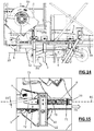
- the motor 5 is driven to make a second displacement of the distributor carriage 3 towards the front (as shown diagrammatically by the arrow D2 on the Figures 14 and 15 ) until the stop 7 returns to the start of the race (ie a return to the rest position), that is to say until the distance measured by the proximity sensor 9 is equal to the distance of rest DR.
- the control unit performs a reset of the reference position of the distributor carriage 3 when the stop 7 is returned to the start of the stroke following the second displacement of the distributor carriage 3, that is to say when the distance measured by the proximity sensor 9 is equal to the rest distance DR. It should be noted that this zeroing can be done a little before the complete return of the stop 7 at the beginning of the race (in other words a little before the complete release of the return member 8) to have a better control of the position of the distributor carriage 3 pushed by the return member 8 and still retained by the rear end 42 of the cable distributor cable 4.
- this method allows an automated registration of the reference position of the distributor carriage 3, which eliminates any risk of error in this reference position and thus allows to have a range indication (or positioning indication of the carriage distributor 3 along the arrow 20) which will always remain fair and reliable.
- Figures 16 and 17 illustrate an alternative embodiment of the abutment 7 described below, using the same numerical references for similar elements or performing the same functions.
- This abutment 7 comprises a rod 70 extended by an enlarged head 72.
- the rod 70 is slidably mounted on the structural element 22 and passes through this structural element 22 in a hole or bearing 23 visible on the Figures 16 and 17 .
- the enlarged head 72 supports a secondary rod 74, parallel to the rod 70, and slidably mounted on the structural element 22 in a hole or bearing 24.
- This a secondary rod 74 provides additional guidance of the translation of the stop 7, and contributes to a better accuracy in the measurement of its displacement.
- the rod 70 has a free end end provided with an abutment surface 71 provided for the distributor carriage 3 to abut against said abutment surface 71.
- the enlarged head 72 has a planar detection surface 73 inclined relative to the direction of sliding DC of the abutment 7 on the structural element 22.
- the detection surface 73 is inclined in the direction of increasing the distance between the proximity sensor 9 and the detection surface 73 when the stop 7 has slid (towards the rear) from its rest position. (illustrated in figure 16 ) to the final working position (illustrated in figure 17 ). In other words, the starting distance DD is less than the ending distance DF.
- This variant therefore has an advantage in the sense that, in the event of a malfunction with excessive thrust exerted by the distributor carriage 3, there is no risk that the stop 7 comes to tap the proximity sensor 9. In fact, when pushing, the stop 7 moves away from the proximity sensor 9.
Abstract
Dispositif de tension (1) automatisée d'un câble distributeur (4) assurant le déplacement d'un chariot distributeur (3) le long d'une flèche de grue, comprenant un moteur coopérant avec le câble pour le déplacement du chariot, un mécanisme tendeur pour régler la tension du câble, et un système de commande automatisée comprenant :
- une butée (7) mobile entre une position de repos et plusieurs positions de travail en présence d'un effort de poussée exercé par le chariot ;
- un organe de rappel (8) sollicitant ladite butée vers sa position de repos et offrant un effort résistant à une poussée exercé par le chariot ; et
- un capteur de proximité (9) détectant la butée dans sa position de repos et ses positions de travail ;
- une unité de pilotage raccordée au moteur et au capteur pour piloter un réglage de la tension du câble en fonction d'une course de la butée entre sa position de repos et ses positions de travail.

- A stop (7) movable between a rest position and several working positions in the presence of a thrust force exerted by the carriage;
- A return member (8) urging said stop towards its rest position and providing a force resistant to thrust exerted by the carriage; and
- a proximity sensor (9) detecting the stop in its rest position and its working positions;
- A control unit connected to the motor and the sensor to control a tension of the cable according to a stroke of the stop between its rest position and its working positions.
Description
La présente invention se rapporte à dispositif de tension automatisée d'un câble distributeur assurant le déplacement d'un chariot distributeur déplaçable le long d'une flèche ditributrice d'une grue.The present invention relates to automated tensioning device of a distributor cable ensuring the displacement of a distributor carriage movable along a ditributrice arrow of a crane.
Elle se rapporte également à une grue de levage, telle qu'une grue à tour, comprenant un tel dispositif de tension, ainsi qu'à un procédé de tension automatisée d'un câble distributeur dans une telle grue.It also relates to a hoisting crane, such as a tower crane, comprising such a tensioning device, as well as to a method of automated tensioning of a distributor cable in such a crane.
Dans le domaine des grues, il est connu du document antérieur
Le câble distributeur présente généralement une grande longueur, pouvant dépasser les 100 mètres selon les longueurs de flèche, qui contribue à ce que le câble distributeur s'allonge pendant le temps de son utilisation, de sorte qu'il est indispensable de retendre ce câble distributeur régulièrement. Généralement, il est nécessaire d'effectuer cette remise en tension du câble distributeur environ deux à trois fois pendant le premier mois d'utilisation de la grue, puis ensuite une fois par trimestre environ.The distributor cable generally has a long length, which may exceed 100 meters depending on the boom lengths, which contributes to the distribution cable lengthening during the time of its use, so that it is essential to tighten this distributor cable. regularly. Generally, it is necessary to perform this re-tensioning of the distributor cable about two to three times during the first month of use of the crane, then thereafter once a quarter.
Cette mise en tension du câble distributeur est en effet nécessaire pour assurer un bon fonctionnement de la translation du chariot distributeur qui n'accepte pas d'avoir un câble distributeur détendu, car le dispositif de sécurité du mou de câble entrerait en action et bloquerait le chariot en position de sécurité conformément aux exigences classiques de sécurité, et en particulier aux indications de la norme européenne EN 14439 sur « appareils de levage à charge suspendue - sécurité - grues à tour ».This tensioning of the distributor cable is indeed necessary to ensure proper operation of the translation of the dispenser carriage which does not accept having a relaxed dispenser cable, because the safety device of the slack cable would come into action and block the trolley in safety position in accordance with the usual safety requirements, and in particular with the indications of the European standard EN 14439 on "cranes - safety - tower cranes".
Cette mise en tension du câble distributeur est également nécessaire pour garantir un fonctionnement réactif de la translation du chariot distributeur et un positionnement précis du chariot distributeur sur la flèche. En effet, à chaque impulsion de déplacement, le chariot distributeur réagit plus vite lorsque le câble distributeur est suffisamment tendu car il n'y aura pas ou peu de mou de câble à récupérer.This tensioning of the distributor cable is also necessary to guarantee a reactive operation of the translation of the distributor carriage and a precise positioning of the distributor carriage on the boom. Indeed, with each movement pulse, the distributor carriage reacts faster when the distributor cable is sufficiently tight because there will be little or no slack cable to recover.
Dans l'exemple du document
Pour faire tourner les deux tambours du dispositif à tambour différentiel, il est aujourd'hui prévu de le faire manuellement au moyen d'une clé de manoeuvre spécifique manipulé par un opérateur placé sur la flèche. Une telle clé de manoeuvre est généralement assez longue, par exemple entre 70 et 120 centimètres, afin que l'opérateur puisse exercer un effort suffisant pour retendre le câble distributeur. Cette opération de retente du câble distributeur constitue une manoeuvre dangereuse à effectuer en hauteur sur la flèche de la grue et ajoute un coût supplémentaire d'exploitation de la grue.To rotate the two drums of the differential drum device, it is now planned to do it manually by means of a specific operating key manipulated by an operator placed on the arrow. Such an operating key is usually quite long, for example between 70 and 120 centimeters, so that the operator can exert sufficient effort to tighten the distributor cable. This re-tensioning operation of the distributor cable constitutes a dangerous maneuver to be performed in height on the boom of the crane and adds an additional cost of operating the crane.
La présente invention a pour but de résoudre en tout ou partie les inconvénients précités, en proposant un dispositif de tension d'un câble distributeur qui soit automatisé, autonome et pilotable directement par le pilote de la grue, donc sans nécessité d'intervention manuelle, contribuant ainsi à améliorer la sécurité pendant l'exploitation de la grue et donc à réduire les frais de maintenance, et à diminuer les temps d'arrêt de maintenance et donc à augmenter la productivité sur le chantier et les coûts d'exploitation de la grue.The present invention aims to solve all or part of the aforementioned drawbacks, by proposing a tensioning device of a distributor cable that is automated, autonomous and controllable directly by the crane driver, so without the need for manual intervention, thus contributing to improving safety during the operation of the crane and thus reducing maintenance costs, and reducing maintenance downtime and thus increasing on-site productivity and operating costs of the crane .
A cet effet, elle propose un dispositif de tension automatisée d'un câble distributeur assurant le déplacement d'un chariot distributeur déplaçable le long d'une flèche distributrice d'une grue, ledit dispositif de tension comprenant un moteur coopérant avec le câble distributeur pour assurer le déplacement du chariot distributeur et comprenant en outre un mécanisme tendeur couplé au câble distributeur pour assurer un réglage de la tension du câble distributeur, ledit dispositif de tension comprenant en outre un système de commande automatisée comprenant :
- une butée montée mobile sur un élément de structure fixe de la grue entre une position de repos en l'absence de poussée exercée par le chariot distributeur sur la butée, et plusieurs positions de travail en présence d'un effort de poussée exercé par le chariot distributeur sur la butée ;
- un organe de rappel élastique sollicitant ladite butée vers sa position de repos et offrant un effort résistant à un effort de poussée exercé par le chariot sur la butée ; et
- un capteur de proximité configuré pour détecter la butée dans sa position de repos et ses positions de travail ;
- une unité de pilotage raccordée au moteur et au capteur de proximité pour piloter ledit moteur, et par conséquent un réglage de la tension du câble distributeur, en fonction d'une course de la butée entre sa position de repos et ses positions de travail.
- a stop mounted on a fixed structure element of the crane between a rest position in the absence of thrust exerted by the carriage dispenser on the stop, and several working positions in the presence of a thrust force exerted by the distributor carriage on the stop;
- an elastic return member urging said stop towards its rest position and offering a force resistant to a thrust force exerted by the carriage on the stop; and
- a proximity sensor configured to detect the stop in its rest position and its working positions;
- a control unit connected to the motor and to the proximity sensor for controlling said motor, and consequently a regulation of the tension of the distributor cable, as a function of a stroke of the stop between its rest position and its working positions.
Ainsi, et comme décrit ultérieurement, un tel dispositif de tension permet de tendre automatiquement le câble distributeur en déplaçant le chariot distributeur qui vient pousser la butée, en fonction de la course de la butée lors de cette poussée. Autrement dit, ce dispositif de tension est automatisé pour faciliter la mise en oeuvre par le grutier, garantir les bonnes manoeuvres et leur précision, et permettre d'avoir une répétabilité maitrisée des séquences et des efforts mis dans le(s) câble(s) de distribution.Thus, and as described later, such a tensioning device can automatically tension the dispenser cable by moving the dispenser carriage which pushes the stopper, depending on the stroke of the stopper during this thrust. In other words, this tensioning device is automated to facilitate the implementation by the crane operator, ensure the right maneuvers and their accuracy, and allow to have mastered repeatability of the sequences and efforts put in the cable (s) of distribution.
Ce dispositif de tension permet également, comme décrit ultérieurement, d'assurer automatiquement une mise à jour du « zéro portée » du chariot distributeur qui correspond à la position de référence du chariot distributeur pour déterminer sa position le long de la flèche, après rétention.This tensioning device also allows, as described later, to automatically ensure an update of the "zero scope" of the distributor carriage which corresponds to the reference position of the distributor carriage to determine its position along the arrow, after retention.
L'organe de rappel élastique est taré à une valeur de raideur prédéfinie en fonction de la tension souhaitée dans le câble distributeur ; l'organe de rappel établissant un effort résistant progressif, en augmentant au fur et à mesure que l'organe de rappel est poussé sous l'effet de la poussée du chariot, jusqu'à une distance de poussée choisie pour établir un effort de tension suffisant dans le câble distributeur pour le bon fonctionnement de la distribution du chariot distributeur.The elastic return member is calibrated to a predefined stiffness value as a function of the desired tension in the distributor cable; the return member establishing a progressive resistance force, increasing as the return member is pushed under the effect of the thrust of the carriage, to a thrust distance chosen to establish a tension force sufficient in the distributor cable for the proper operation of the dispenser carriage.
Selon une caractéristique, la butée est montée coulissante en translation sur l'élément de structure fixe de la grue.According to one characteristic, the stop is slidably mounted in translation on the fixed structure element of the crane.
En variante, la butée est montée pivotante sur l'élément de structure fixe de la grue.Alternatively, the stop is pivotally mounted on the fixed structure member of the crane.
Selon une autre caractéristique, la butée présente une première extrémité présentant une surface de butée pour le chariot distributeur, et une seconde extrémité présentant une surface de détection pour le capteur de proximité positionné en regard de cette surface de détection.According to another feature, the stop has a first end having a stop surface for the distributor carriage, and a second end having a detection surface for the proximity sensor positioned opposite this detection surface.
Dans une réalisation particulière, la surface de détection de la butée est une surface plane inclinée relativement à une direction de coulissement en translation de ladite butée.In a particular embodiment, the detection surface of the abutment is a flat surface inclined relative to a sliding direction in translation of said abutment.
Ainsi, la distance entre la surface de détection et le capteur de proximité varie en fonction du déplacement translatif de la butée.Thus, the distance between the detection surface and the proximity sensor varies as a function of the translational movement of the stop.
Dans un mode de réalisation particulier, la butée traverse l'élément de structure fixe de sorte que la surface de butée et la surface de détection sont disposées de part et d'autre de l'élément de structure fixe.In a particular embodiment, the abutment passes through the fixed structural element so that the abutment surface and the detection surface are disposed on either side of the fixed structural element.
Avantageusement, l'organe de rappel élastique est intercalé entre l'élément de structure fixe et la surface de butée prévue à la première extrémité de la butée.Advantageously, the elastic return member is interposed between the fixed structural element and the abutment surface provided at the first end of the abutment.
Selon une possibilité de l'invention, le dispositif de tension comprend au moins un treuil de distribution accouplé au moteur et comprenant un tambour d'enroulement, où :
- un brin avant du câble distributeur présente une première extrémité fixée sur un premier côté du tambour d'enroulement et une seconde extrémité opposée fixée sur le mécanisme tendeur, ce brin avant passant par au moins une poulie de renvoi disposée en pointe de la flèche distributrice ; et
- un brin arrière du câble distributeur présente une première extrémité fixée sur un second côté du tambour d'enroulement et une seconde extrémité opposée fixée sur le mécanisme tendeur, ce brin arrière passant par au moins une poulie de renvoi disposée au pied de la flèche distributrice.
- a front end of the distributor cable has a first end fixed on a first side of the winding drum and an opposite second end fixed to the tensioning mechanism, this front strand passing through at least one deflection pulley arranged in a point of the dispensing boom; and
- a rear end of the distributor cable has a first end attached to a second side of the winding drum and an opposite second end fixed to the tensioning mechanism, the rear end passing through at least one return pulley disposed at the foot of the dispensing boom.
Selon une autre possibilité de l'invention, le mécanisme tendeur comprend un dispositif à tambour différentiel monté rotatif sur le chariot distributeur et comprenant :
- deux tambours de diamètres distincts et solidaires en rotation, la seconde extrémité du brin avant du câble distributeur étant fixée pour s'enrouler sur un tambour de plus grand diamètre et la seconde extrémité du brin arrière du câble distributeur étant fixée pour s'enrouler sur un tambour de plus petit diamètre, où le brin avant et le brin arrière sont enroulés de sorte que, d'une part, une rotation des deux tambours selon un premier sens de rotation entraîne un déroulement du brin avant sur le tambour de plus grand diamètre et un enroulement du brin arrière sur le tambour de plus petit diamètre et, d'autre part, une rotation des deux tambours selon un second sens de rotation entraîne un enroulement du brin avant sur le tambour de plus grand diamètre et un déroulement du brin arrière sur le tambour de plus petit diamètre ; et
- un système de blocage principal coopérant avec les tambours pour interdire la rotation des tambours selon ledit premier sens de rotation.
- two drums of different diameters and fixed in rotation, the second end of the front end of the distributor cable being fixed to wind on a larger diameter drum and the second end of the rear end of the distributor cable being fixed to wind on a drum of smaller diameter, wherein the front and rear strands are wound so that, on the one hand, a rotation of the two drums in a first direction of rotation causes unwinding of the front strand on the drum of larger diameter and a winding of the rear run on the drum of smaller diameter and, on the other hand, a rotation of the two drums in a second direction of rotation causes winding of the front run on the larger diameter drum and unwinding of the rear run on the smaller diameter drum; and
- a main locking system cooperating with the drums to prohibit the rotation of the drums in said first direction of rotation.
Ce mécanisme tendeur avec dispositif à tambour différentiel est particulièrement bien adapté pour l'invention, sans pour autant que d'autres types de mécanismes tendeurs puissent être envisagés, comme par exemple des mécanismes avec tambour avaleur. Il est à noter que le premier sens de rotation des tambours du dispositif à tambour différentiel se traduit par un relâchement (ou une baisse) de la tension dans le câble distributeur. Il est à noter qu'une rotation des deux tambours selon le second sens de rotation correspond à une mise en tension du câble distributeur, autrement dit à une augmentation de la tension dans le câble distributeur.This tensioning mechanism with differential drum device is particularly well suited to the invention, without other types of tensioning mechanisms can be envisaged, such as mechanisms with swallowing drum. It should be noted that the first direction of rotation of the drums of the differential drum device results in a loosening (or a decrease) of the tension in the distributor cable. It should be noted that a rotation of the two drums in the second direction of rotation corresponds to a tensioning of the distributor cable, in other words to an increase of the tension in the distributor cable.
Avantageusement, le mécanisme tendeur comprend un système de blocage secondaire déplaçable sélectivement entre :
- une configuration fermée dans lequel il coopère avec les tambours pour interdire la rotation des tambours également selon le second sens de rotation ; et
- une configuration ouverte dans lequel il autorise la rotation des tambours selon ledit second sens de rotation.
- a closed configuration in which it cooperates with the drums to prohibit the rotation of the drums also in the second direction of rotation; and
- an open configuration in which it allows the rotation of the drums according to said second direction of rotation.
Ainsi, pendant le travail de distribution de la charge par le chariot distributeur le long de la flèche distributrice, le système de blocage secondaire peut être déplacé en configuration fermée de sorte que les deux tambours du dispositif à tambour différentiel sont bloqués dans les deux sens de rotation, ce qui présente l'avantage d'éviter une reprise des efforts de balan lors de changements de sens de déplacement du chariot distributeur. Il est à noter que le second sens de rotation des tambours du dispositif à tambour différentiel se traduit par un accroissement (ou une augmentation) de la tension dans le câble distributeur.Thus, during the work of distributing the load by the distributor carriage along the dispensing boom, the secondary locking system can be moved in closed configuration so that the two drums of the differential drum device are locked in both directions of rotation. rotation, which has the advantage of avoiding a resumption of balan forces during changes in direction of movement of the distributor carriage. It should be noted that the second direction of rotation of the drums of the differential drum device results in an increase (or an increase) in the tension in the distributor cable.
Par contre, pendant le travail de réglage de la tension du câble distributeur, le système de blocage secondaire est déplacé en configuration ouverte et ainsi le réglage de la tension n'est autorisé que dans une zone bien définie, en particulier en pied de flèche, et sous réserve que ledit système de blocage secondaire soit bien en configuration ouverte.On the other hand, during the work of adjusting the tension of the distributor cable, the secondary locking system is moved in open configuration and thus the adjustment of the tension is authorized only in a well-defined zone, in particular at the foot of the arrow, and provided that said secondary locking system is in an open configuration.
Selon une variante, le système de blocage secondaire est absent, et la rotation des tambours selon le second sens de rotation est constamment autorisée.According to one variant, the secondary locking system is absent, and the rotation of the drums according to the second direction of rotation is constantly allowed.
Conformément à une autre caractéristique avantageuse de l'invention, le capteur de proximité est un capteur inductif ou un capteur lumineux.According to another advantageous characteristic of the invention, the proximity sensor is an inductive sensor or a light sensor.
Avantageusement, la butée est montée mobile sur un élément de structure disposé en pied de la flèche distributrice de la grue, de sorte que le pilote de grue puisse avoir une vision suffisamment proche du chariot distributeur pendant l'opération de réglage de la tension.Advantageously, the stop is movably mounted on a structural element disposed at the foot of the crane dispensing boom, so that the crane driver can have a vision sufficiently close to the distributor carriage during the tension adjustment operation.
La présente invention concerne également une grue de levage comprenant une flèche distributrice le long de laquelle est déplaçable un chariot distributeur, ladite grue comprenant un dispositif de tension selon l'invention, où le chariot distributeur est déplaçable dans une configuration de réglage dans laquelle le chariot distributeur exerce une poussée sur la butée, à l'encontre de l'organe de rappel élastique, provoquant un déplacement de la butée jusqu'à une position de travail prédéfinie détectée par le capteur de proximitéThe present invention also relates to a hoisting crane comprising a distributing boom along which is movable a trolley, said crane comprising a tensioning device according to the invention, wherein the trolley is movable in a setting configuration in which the trolley distributor exerts a thrust on the stop, against the elastic return member, causing a displacement of the stop to a predefined working position detected by the proximity sensor
L'invention se rapporte aussi à un procédé de tension automatisée d'un câble distributeur dans une grue conforme à l'invention, comprenant les étapes suivantes :
- détection de la butée par le capteur de proximité en position de repos, correspondant à un début de course de réglage ;
- premier déplacement du chariot distributeur selon un premier sens de translation jusqu'à venir en appui sur la butée puis exercer une poussée sur la butée, à l'encontre de l'organe de rappel élastique, provoquant un déplacement de la butée jusqu'à une position de travail prédéfinie détectée par le capteur de proximité, correspondant à une fin de course de réglage ;
- mise en tension du câble distributeur par le mécanisme tendeur concomittament au déplacement du chariot distributeur jusqu'à la fin de course de la butée ;
- second déplacement du chariot distributeur selon un second sens de translation, opposé au premier sens de translation, jusqu'au retour de la butée en début de course.
- detection of the stop by the proximity sensor in the rest position, corresponding to a start of the adjustment stroke;
- first displacement of the distributor carriage in a first direction of translation until it bears against the abutment and then exerting a thrust on the abutment, against the elastic return member, causing displacement of the abutment to a stop predefined working position detected by the proximity sensor, corresponding to a limit switch;
- tensioning of the distributor cable by the tensioning mechanism concomitantly with the displacement of the distributor carriage until the end of travel of the stop;
- second displacement of the distributor carriage in a second direction of translation, opposite the first direction of translation, until the return of the stop at the beginning of travel.
Ainsi, le câble distributeur est tendu automatiquement, à une tension dépendante de la valeur de raideur prédéfinie de l'organe de rappel élastique, sans intervention manuelle.Thus, the distributor cable is tensioned automatically, at a voltage dependent on the predetermined stiffness value of the elastic return member, without manual intervention.
Il est à noter que le premier sens de translation peut être un sens de déplacement vers l'arrière (autrement dit en direction du pied de flèche) tandis que le second sens de translation est un sens de déplacement vers l'avant (autrement dit en direction de la pointe de flèche), si l'ensemble butée/capteur de proximité/organe de rappel élastique est situé en pied de flèche.It should be noted that the first direction of translation may be a direction of movement towards the rear (in other words towards the foot of arrow) whereas the second direction of translation is a direction of displacement towards the front (in other words in direction of the arrowhead), if the stop / proximity sensor / resilient return member assembly is located at the foot of the arrow.
Cependant, il peut être prévu que le premier sens de translation soit un sens de déplacement vers l'avant et que le second sens de translation soit un sens de déplacement vers l'arrière, si l'ensemble butée/capteur de proximité/organe de rappel élastique est situé en pointe de flèche.However, it may be provided that the first direction of translation is a forward direction of travel and that the second direction of translation is a backward direction of movement, if the abutment assembly / proximity sensor / organ of displacement. elastic return is located in arrowhead.
Avantageusement, le procédé de tension comprend une étape de mise à zéro d'une position de référence du chariot distributeur lorsque la butée est retournée en début de course suite au second déplacement du chariot distributeur.Advantageously, the tensioning method comprises a step of zeroing a reference position of the distributor carriage when the stop is returned to the start of the stroke following the second displacement of the distributor carriage.
Ainsi le procédé de tension permet de recaler automatiquement le « zéro portée » du chariot distributeur qui correspond à la position de référence du chariot distributeur pour déterminer sa position le long de la flèche. Avec l'automatisation de ce recalage, le risque d'erreur sur cette position de référence est supprimé et l'indication de portée restera toujours juste et fiable.Thus, the tensioning method automatically resets the "zero scope" of the distributor carriage which corresponds to the reference position of the distributor carriage to determine its position along the arrow. With the automation of this registration, the risk of error in this reference position is eliminated and the range indication will always remain accurate and reliable.
Selon une possibilité, le premier déplacement du chariot distributeur est effectuée à partir d'une position de départ détectée par un détecteur de présence, et ce déplacement est autorisé à la condition où ledit détecteur de présence a détecté la présence dudit chariot distributeur en position de départ.According to one possibility, the first displacement of the distributor carriage is made from a starting position detected by a presence detector, and this movement is authorized on condition that said presence detector has detected the presence of said distributor carriage in the position of departure.
Selon une autre possibilité, le premier déplacement du chariot distributeur est effectué sous réserve que les conditions suivantes soient remplies :
- au moins une moufle de levage portant un organe de levage et suspendue au chariot ditributeur par un câble de levage est en position haute non descendue ;
- un effort de charge sur l'organe de levage est mesuré comme étant inférieur à 5 % d'une charge maximale prédéfinie.
- at least one lifting muffle carrying a lifting member and suspended from the trolley by a hoisting cable is in the up position not descended;
- a loading force on the lifting member is measured as being less than 5% of a predefined maximum load.
Selon une autre possibilité, le premier déplacement du chariot distributeur est effectué sous l'action d'une commande manuelle exercée par un pilote de la grue.According to another possibility, the first movement of the distributor carriage is performed under the action of a manual control exerted by a driver of the crane.
D'autres caractéristiques et avantages de la présente invention apparaîtront à la lecture de la description détaillée ci-après, d'un exemple de mise en oeuvre non limitatif, faite en référence aux figures annexées dans lesquelles :
- la
figure 1 est une vue schématique en perspective d'une partie de la grue conforme à l'invention ; - la
figure 2 est une vue schématique zoomée de la zone II de lafigure 1 qui est positionnée sur l'ensemble butée/capteur de proximité/organe de rappel élastique ; - la
figure 3 est une vue schématique de dessus d'une partie de la grue de lafigure 1 ; - la
figure 4 est une vue schématique de côté d'une partie de la grue de lafigure 1 ; - la
figure 5 est une vue schématique en perspective de dessous d'une partie de la grue de lafigure 1 ; - la
figure 6 est une vue schématique en perspective d'un dispositif à tambour différentiel ; - la
figure 7 est une vue schématique partielle de dessus d'une partie de la grue de lafigure 1 , illustrant un exemple de réalisation d'un système de blocage secondaire ; - les
figures 8 sont des vues schématiques de côté du système de blocage secondaire en situation, respectivement dans une configuration fermée (et 9figure 8 ) et dans une configuration ouverte (figure 9 ) ; - la
figure 10 est une vue schématique de côté d'une partie de la grue de lafigure 1 , dans une première configuration où le chariot distributeur est en contact avec la butée lors de son premier déplacement, la butée étant alors en début de course de réglage ; - la
figure 11 une vue zoomée de la zone XI de lafigure 10 ; - la
figure 12 une vue schématique équivalente à celle de lafigure 10 , dans une deuxième configuration (qui fait suite à la première configuration) où le chariot distributeur a terminé son premier déplacement et a poussé la butée jusqu'à une position de travail finale correspondant à une fin de course de réglage ; - la
figure 13 une vue zoomée de la zone XIII de lafigure 12 ; - la
figure 14 une vue schématique équivalente à celle de lafigure 10 ou12 , dans une troisième configuration (qui fait suite à la deuxième configuration) où le chariot distributeur a effectué son second déplacement jusqu'au retour de la butée en début de course ; - la
figure 15 une vue zoomée de la zone XV de lafigure 14 ; et - les
figures 16 et 17 sont des vues schématiques de côté d'une variante de réalisation de la butée, respectivement dans une position de repos en début de course de réglage (figure 16 ) et dans une position de travail finale en fin de course de réglage (figure 17 ).
- the
figure 1 is a schematic perspective view of a portion of the crane according to the invention; - the
figure 2 is a zoomed schematic view of zone II of thefigure 1 which is positioned on the stop / proximity sensor / resilient return member assembly; - the
figure 3 is a schematic view from above of a part of the crane of thefigure 1 ; - the
figure 4 is a schematic side view of a part of the crane of thefigure 1 ; - the
figure 5 is a schematic perspective view from below of a part of the crane of thefigure 1 ; - the
figure 6 is a schematic perspective view of a differential drum device; - the
figure 7 is a partial schematic view from above of a part of the crane of thefigure 1 illustrating an exemplary embodiment of a secondary locking system; - the
Figures 8 and 9 are schematic side views of the secondary blocking system in situation, respectively in a closed configuration (figure 8 ) and in an open configuration (figure 9 ); - the
figure 10 is a schematic side view of a part of the crane of thefigure 1 in a first configuration where the distributor carriage is in contact with the stop during its first displacement, the stop being then at the beginning of the adjustment stroke; - the
figure 11 a zoomed view of area XI of thefigure 10 ; - the
figure 12 a schematic view equivalent to that of thefigure 10 in a second configuration (which follows the first configuration) where the distributor carriage has completed its first displacement and pushed the stop to a final working position corresponding to an adjustment limit switch; - the
figure 13 a zoomed view of area XIII of thefigure 12 ; - the
figure 14 a schematic view equivalent to that of thefigure 10 or12 in a third configuration (which follows the second configuration) where the distributor carriage has made its second displacement until the return of the stop at the start of the race; - the
figure 15 a zoomed view of the XV zone of thefigure 14 ; and - the
Figures 16 and 17 are schematic side views of an alternative embodiment of the stop, respectively in a rest position at the start of the adjustment stroke (figure 16 ) and in a final working position at the end of the adjustment stroke (figure 17 ).
En référence aux
Le chariot distributeur 3 circule sur un chemin de roulement entre le pied de la flèche et la pointe de la flèche (ou extrémité libre de la flèche), et supporte un organe de levage 30 (tel qu'un crochet) monté sur une moufle de levage 31 suspendue au chariot ditributeur 3 par un câble de levage 32.The
Le chariot distributeur 3 est déplaçable vers l'avant (autrement dit en direction de la pointe de la flèche), et également vers l'arrière (autrement dit en direction du pied de la flèche).The
Le dispositif de tension 1 est prévu pour permettre un réglage automatisé par le pilote de grue (ou grutier) de la tension du câble distributeur 4 assurant le déplacement du chariot distributeur 3 vers l'avant et vers l'arrière.The
Ce dispositif de tension 1 comprend un moteur 5 coopérant avec le câble distributeur 4 pour assurer le déplacement du chariot distributeur 3 et comprenant en outre un mécanisme tendeur 6 couplé au câble distributeur 4 pour assurer un réglage de la tension du câble distributeur 4.This
Comme visible sur la
- un
grand tambour 61 qui constitue le tambour de plus grand diamètre ; et un petit tambour 62 qui constitue le tambour de plus petit diamètre ;
- a
large drum 61 which constitutes the drum of larger diameter; and - a
small drum 62 which constitutes the drum of smaller diameter;
Le câble distributeur 4 est accouplé à un treuil de distribution monté en pied de flèche et comprenant un tambour d'enroulement 50 entraîné en rotation par le moteur 5 selon deux sens de rotation opposés, de sorte que la rotation du moteur 5 entraîne le déplacement du chariot distributeur 3 vers l'avant ou vers l'arrière selon le sens de rotation du tambour d'enroulement 50.The
Le câble distributeur 4 est accouplé à la fois au tambour d'enroulement 50 du treuil de distribution et aux tambours 61, 62 du mécanisme tendeur 6 de la manière suivante, en référence à la
un brin avant 41 du câble distributeur 4 présente :- une première extrémité 411 fixée pour s'enrouler sur un premier côté du tambour d'enroulement 50 et
- une seconde extrémité 412 opposée fixée pour s'enrouler sur le
grand tambour 61 du mécanisme tendeur 6 ; - où
ce brin avant 41 passe par une poulie de renvoi (non visible sur les figures) disposée à la pointe de la flèche 20 ; et
- un brin arrière 42 du câble distributeur 4 présente :
- une première extrémité 421 fixée pour s'enrouler sur un second côté du tambour d'enroulement 50 ; et
- une seconde extrémité 422 opposée fixée pour s'enrouler sur le
petit tambour 62 du mécanisme tendeur 6 ; - où ce brin arrière 42 passe par une poulie de renvoi 43 disposée au pied de la flèche 20.
- a
front end 41 of thedistributor cable 4 has:- a
first end 411 fixed to wind on a first side of the windingdrum 50 and - a
second end 412 opposite fixed to wind on thelarge drum 61 of thetensioning mechanism 6; - where this
front strand 41 passes through a return pulley (not visible in the figures) disposed at the tip of theboom 20; and
- a
- a
rear end 42 of thedistributor cable 4 has:- a
first end 421 fixed to wind on a second side of the windingdrum 50; and - a
second end 422 opposite fixed to wind on thesmall drum 62 of thetensioning mechanism 6; - where this
rear run 42 passes through adeflection pulley 43 disposed at the foot of theboom 20.
- a
Ainsi, le brin avant 41 présente une longueur sensiblement équivalente au double de la longueur de la flèche 20, tandis que le brin arrière 42 présente une longueur sensiblement équivalente à la longueur de la flèche 20.Thus, the
Pour un déplacement du chariot distributeur 3 vers l'avant, le moteur 5 fait tourner le tambour d'enroulement 50 selon un sens de rotation dit sens avant qui correspond à un enroulement du brin avant 41 sur le tambour d'enroulement 50 et à un déroulement du brin arrière 42 sur le tambour d'enroulement 50. Pour un déplacement du chariot distributeur 3 vers l'arrière, le moteur 5 fait tourner le tambour d'enroulement 50 selon un sens de rotation dit sens arrière, opposé au sens avant, qui correspond à un déroulement du brin avant 41 sur le tambour d'enroulement 50 et à un enroulement du brin arrière 42 sur le tambour d'enroulement 50.For a displacement of the
Le dispositif à tambour différentiel comprend un système de blocage principal 80 coopérant avec les tambours 61, 62 pour :
- interdire la rotation des tambours 61, 62 selon un premier sens de rotation S1 correspondant à un déroulement du
brin avant 41 sur legrand tambour 61 et à un enroulement du brin arrière sur lepetit tambour 62 et - autoriser la rotation des tambours 61, 62 selon un second sens de rotation S2, opposé au premier sens de rotation S1, où ce second sens de rotation S2 correspond à un enroulement du
brin avant 41 sur legrand tambour 61 et à un déroulement du brin arrière sur lepetit tambour 62.
- prohibiting the rotation of the
drums front strand 41 on thelarge drum 61 and a winding of the rear strand on thesmall drum 62 and - allow rotation of the
drums front strand 41 on thelarge drum 61 and to a strand unwinding back on thesmall drum 62.
Ce premier sens de rotation S1 des tambours 61, 62 se traduit par un relâchement (ou une baisse) de la tension dans le câble distributeur 4. Ce système de blocage principal a pour fonction d'éviter justement un tel relâchement de la tension dans le câble distributeur 4. A l'inverse, ce second sens de rotation S2 des tambours 61, 62 se traduit par un accroissement (ou une augmentation) de la tension dans le câble distributeur 4.This first direction of rotation S1 of the
Comme visible sur la
Comme illustré sur la
- un système à crans unidirectionnel comprenant des crans (ou dents) 81 en périphérie de l'un des tambours 61, 62 ou d'une roue crantée 82 solidaire des tambours 61, 62 ainsi qu'illustré sur la
figure 6 , et - au moins un cliquet 83 pivotant propre à se bloquer dans les crans 81 pour un blocage pour interdire la rotation des tambours 61, 62 selon le premier sens de rotation S1, tout en autorisant la rotation des tambours 61, 62 selon un second sens de rotation S2 opposé au premier sens de rotation ; et
- au moins un organe élastique de rappel (non illustré) sollicitant le cliquet 83 vers une position de blocage dans les crans 81.
- a unidirectional notch system comprising notches (or teeth) 81 on the periphery of one of the
drums wheel 82 integral with thedrums figure 6 , and - at least one pivoting pawl 83 adapted to lock in the
notches 81 for a locking to prevent the rotation of thedrums drums - at least one elastic return member (not shown) urging the pawl 83 towards a locking position in the
notches 81.
La roue crantée 82 est solidaire en rotation de l'axe 63.The
Le mécanisme tendeur 6 peut également comprendre un système de blocage secondaire 90 déplaçable sélectivement entre :
- une configuration fermée dans lequel il coopère avec les tambours 61, 62 pour interdire la rotation des tambours 61, 62 également selon le second sens de rotation S2; et
- une configuration ouverte dans lequel il autorise la rotation des tambours 61, 62 selon ce second sens de rotation S2.
- a closed configuration in which it cooperates with the
drums drums - an open configuration in which it allows the rotation of the
drums
Ce système de blocage secondaire 90 est distinct du système de blocage principal précité. Le second sens de rotation S2 des tambours 61, 62 se traduit pour rappel par un accroissement (ou une augmentation) de la tension dans le câble distributeur 4.This
Ce système de blocage secondaire 90 a pour fonctions de :
- en configuration fermée, pendant le travail de distribution de la charge par le chariot distributeur 3 le long de la flèche 20, bloquer la rotation des tambours 61, 62 selon ce second sens de rotation, ces tambours 61, 62 étant par ailleurs déjà bloqués en rotation selon le premier sens de rotation grâce au système de blocage principal ; et
- en configuration ouverte, pendant la mise en tension du câble distributeur 4, ainsi que décrit ultérieurement, autoriser la rotation des tambours 61, 62 selon ce second sens de rotation S2, cette rotation selon ce second sens de rotation S2 étant nécessaire pour tendre le câble distributeur 4.
- in the closed configuration, during the work of distributing the load by the
distributor carriage 3 along thearrow 20, blocking the rotation of thedrums drums - in the open configuration, during the tensioning of the
distributor cable 4, as described later, allow the rotation of thedrums cable distributor 4.
Les
Ce système de blocage secondaire 90 comprend :
- un système à crans unidirectionnel comprenant des crans (ou dents) 91 en périphérie de l'un des tambours 61, 62 ou d'une roue crantée 92 solidaire des tambours 61, 62, et
un cliquet 93 pivotant propre à se bloquer dans les crans 91 pour un blocage pour interdire la rotation des tambours 61, 62 selon le second sens de rotation S2 ; et- au moins un organe élastique de rappel (non illustré) sollicitant le cliquet 93 vers une position de blocage dans les crans 91 ; et
un actionneur 94 mobile déplaçable sélectivement entre :- une position de repos (visible sur la
figure 8 ) dans laquelle l'actionneur 94 n'agit pas sur le cliquet 93 qui reste en position de blocage dans les crans 91 pour interdire la rotation des tambours 61, 62 selon le second sens de rotation S2 ; et - une position de déverrouillage (visible sur la
figure 9 ) dans laquelle l'actionneur 94 agit sur le cliquet 93 (en appuyant dessus) pour le débloquer des crans 91 et ainsi autoriser la rotation des tambours 61, 62 selon le second sens de rotation S2.
- une position de repos (visible sur la
- a unidirectional detent system comprising notches (or teeth) 91 on the periphery of one of the
drums toothed wheel 92 integral with thedrums - a pivoting
pawl 93 adapted to lock in thenotches 91 for locking to prevent the rotation of thedrums - at least one elastic return member (not shown) urging the
pawl 93 to a locking position in thenotches 91; and - a
movable actuator 94 movable selectively between:- a rest position (visible on the
figure 8 ) in which theactuator 94 does not act on thepawl 93 which remains in the locked position in thenotches 91 to prevent the rotation of thedrums - an unlocking position (visible on the
figure 9 ) in which theactuator 94 acts on the pawl 93 (pressing on it) for the to unlocknotches 91 and thus allow the rotation of thedrums
- a rest position (visible on the
La roue crantée 92 est solidaire en rotation de l'axe 63. Il est envisageable que les deux tambours 61, 62 soient encadrés par la roue crantée 82 d'un côté et la roue crantée 92 de l'autre côté.The
Ce système de blocage secondaire 90 est ainsi inversé dans son fonctionnement par rapport au système de blocage principal 80. Ainsi, les crans 91 sont tournés dans le sens inverse par rapport aux crans 81.This
Le cliquet 93 est monté sur le chariot distributeur 3 et reste en position de blocage (visible sur les
L'actionneur 94 est monté sur la flèche de la grue, en pied de flèche, et occupe sa position de repos pendant le travail de distribution de la charge par le chariot distributeur 3, sans agir avec le cliquet 93 ; le système de blocage secondaire 90 est alors en configuration fermée.The
Par contre, en amont ou au début du procédé de tension automatisée, lorsque le chariot distributeur 3 est en pied de flèche, l'actionneur 94 est commandé vers sa position de déverrouillage pour débloquer le cliquet 93 et ainsi autoriser la rotation des tambours 61, 62 selon le second sens de rotation S2; le système de blocage secondaire 90 est alors en configuration ouverte.On the other hand, upstream or at the beginning of the automated tensioning process, when the
Le dispositif de tension 1 comprend en outre un système de commande automatisée 10 qui permet de commander la mise en tension du câble distributeur 4 de manière automatique.The
Ce système de commande automatisée 10 comprend une butée 7 montée coulissante en translation sur un élément de structure 22 fixe de la grue 2 placé en pied de flèche, de sorte que la butée 7 se situe en face du chariot distributeur 3 lorsque ce dernier est sensiblement en début de course au pied de la flèche 20.This automated control system 10 comprises an
Cette butée 7 comprend une tige 70 prolongée par une tête élargie 72. La tige 70 est montée coulissante sur l'élément de structure 22 et, à ce titre, la tige 70 traverse cet élément de structure 22 dans un orifice ou palier.This
La tige 70 présente une extrémité avant libre munie d'une surface de butée 71 prévue pour que le chariot distributeur 3 vienne en butée contre ladite surface de butée 71. A ce titre, le chariot distributeur 3 peut présenter, sur l'arrière, un butoir arrière 33 propre à venir en appui sur la surface de butée 71.The
Cette surface de butée 71 est élargie relativement à la tige 70, et se présente notamment sous la forme d'un disque de diamètre supérieur au diamètre de la tige 70 si celle-ci est cylindrique.This
La tige 70 présente une extrémité arrière, opposée à l'extrémité avant et donc à la surface de butée 71, sur laquelle est fixée la tête élargie 72. Ainsi, la butée 7 présente de part et d'autre de l'élément de structure 22 :
- une première extrémité présentant la surface de butée 71 et
- une seconde extrémité présentant la tête élargie 72.
- a first end having the
abutment surface 71 and - a second end having the
enlarged head 72.
La tête élargie 72 présente une surface de détection 73 plane et inclinée relativement à la direction de coulissement DC de la butée 7 sur l'élément de structure 22.The
Ce système de commande automatisée 10 comprend en outre un organe de rappel 8 élastique intercalée entre l'élément de structure 22 et la surface de butée 71, où cet organe de rappel 8 se présente sous la forme d'un ressort hélicoïdal de compression monté autour de la tige 70.This automated control system 10 further comprises an
Le système de commande automatisée 10 comprend également un capteur de proximité 9 monté fixement sur la flèche 20 et disposée en regard de la surface de détection 73 de la tête élargie 72 de la butée 7, où le capteur de proximité 9 est configuré pour détecter et mesurer la distance entre ledit capteur de proximité 9 et ladite surface de détection 73.The automated control system 10 also comprises a
Ce capteur de proximité 9 peut par exemple être un capteur inductif ou un capteur lumineux (capteur infrarouge, ...).This
La butée 7 est déplaçable sélectivement entre :
- une position de repos (visible sur les
figures 2 ,10 et 11 ) en l'absence de poussée exercée par le chariot distributeur 3 sur la butée 7, autrement dit en l'absence d'effort de poussée exercé vers l'arrière (autrement dit en direction du pied de flèche) par le butoir arrière 33 du chariot distributeur 3 sur la surface de butée 71 de la butée 7, étant noté que l'organe de rappel 8 sollicite cette butée 7 vers sa position de repos ; et - plusieurs positions de travail en présence d'un effort de poussée exercé par le chariot distributeur 3 sur la butée 7, autrement dit en présence d'un effort de poussée exercé vers l'arrière par le butoir arrière 33 du chariot distributeur 3 sur la surface de butée 71 de la butée 7, étant noté que l'organe de rappel 8 offre un effort résistant à cet effort de poussée exercé par le chariot distributeur 3 sur la butée 7.
- a rest position (visible on
figures 2 ,10 and 11 ) in the absence of thrust exerted by thetrolley 3 on thestop 7, that is to say in the absence of pushing force exerted backwards (ie in the direction of the foot of the arrow) by therear stopper 33 of thetrolley distributor 3 on theabutment surface 71 of theabutment 7, being noted that thereturn member 8 urges theabutment 7 to its rest position; and - several working positions in the presence of a thrust force exerted by the
distributor carriage 3 on thestop 7, in other words in the presence of a thrust force exerted backwards by therear stopper 33 of thedistributor carriage 3 on the surface stop 71 of theabutment 7, being noted that thereturn member 8 provides a force resistant to this thrust force exerted by thedistributor carriage 3 on thestop 7.
Dans les positions de travail, la butée 7 a coulissé (vers l'arrière), comparativement à la position de repos, ce qui contribue à une modification de la distance entre le capteur de proximité 9 et la surface de détection 73, et aussi à une compression de l'organe de rappel 8 entre l'élément de structure 22 et la surface de butée 71.In the working positions, the
Il est à noter que la surface de détection 73 est inclinée dans le sens d'une réduction de la distance entre le capteur de proximité 9 et la surface de détection 73 lorsque la butée 7 a coulissé (vers l'arrière) de sa position de repos vers une position de travail.It should be noted that the
Comme le capteur de proximité 9 est configuré pour détecter et mesurer la distance entre le capteur de proximité 9 et la surface de détection 73, ce capteur de proximité 9 est alors configuré pour détecter la butée 7 dans sa position de repos et dans ses positions de travail.As the
Le système de commande automatisée 10 comprend aussi une unité de pilotage (non illustrée), de préférence placée dans la cabine de pilotage de la grue 2, qui est raccordée à la fois :
au moteur 5 pour piloter le déplacement du chariot distributeur 3 vers l'avant et vers l'arrière ; et- au capteur de proximité 9 pour récupérer en temps réel la distance mesurée entre ce capteur de proximité 9 et la surface de détection 73 de la butée 7 ;
- the
motor 5 to control the movement of thedistributor carriage 3 forwards and backwards; and - the
proximity sensor 9 to recover in real time the distance measured between thisproximity sensor 9 and thedetection surface 73 of thestop 7;
Il est à noter que l'ensemble butée 7, élément de structure 22, organe de rappel 8 et capteur de proximité 9 est disposé en pied de la flèche 20 distributrice de la grue 2, de sorte que le pilote de grue puisse avoir une vision suffisamment proche du chariot distributeur 3 pendant le procédé de tension automatisée du câble distributeur 4 décrit ci-après.It should be noted that the
Ce procédé de tension automatisée comprend les étapes suivantes.This automated tensioning method comprises the following steps.
Dans une première étape, le chariot distributeur 3 est placé dans une position de départ, par exemple celle illustrée sur les
Cette position de départ du chariot distributeur 3 correspond sensiblement à une position de référence du chariot distributeur 3, qui sera mise à jour à l'issue du procédé (comme décrit ultérieurement), qui est sa position en début de course au niveau du pied de flèche. Cette position de référence sert de point de départ pour déterminer la position du chariot distributeur 3 le long de la flèche 20.This starting position of the
Dans cette première étape ou après cette première étape, il est prévu que le système de blocage secondaire 90, lorsque présent, bascule en configuration ouverte. Ce basculement peut être effectué par un système mécanique passif ou par un système motorisé.In this first step or after this first step, it is expected that the
Dans cette première étape ou après cette première étape, l'unité de de pilotage récupère la distance de départ DD mesurée entre le capteur de proximité 9 et la surface de détection 73 de la butée 7, alors que la butée 7 est en position de repos. Autrement dit, il est prévu une détection de la butée 7 par le capteur de proximité 9 en position de repos ; cette position de repos de la butée 7 correspondant à un début de course de réglage.In this first step or after this first step, the control unit recovers the departure distance DD measured between the
En préalable à cette première étape ou après cette première étape, le pilote de grue initie la séquence d'étapes sous l'action d'une commande manuelle, par exemple sur un bouton d'activation (bouton spécifique, bouton sur écran tactile, ...).Prior to this first step or after this first step, the crane driver initiates the sequence of steps under the action of a manual control, for example on an activation button (specific button, button on touch screen,. ..).
La deuxième étape consiste à vérifier si les conditions suivantes sont remplies :
- le détecteur de présence a détecté la présence du chariot distributeur 3 en position de départ ;
- la moufle de levage 31 portant l'organe de levage 30 est en position haute non descendue ;
- un effort de charge sur l'organe de levage 30 est mesuré comme étant inférieur à 5 % d'une charge maximale prédéfinie.
- the presence detector has detected the presence of the
distributor carriage 3 in the starting position; - the lifting muffle 31 carrying the lifting
member 30 is in the up position not descended; - a loading force on the lifting
member 30 is measured as less than 5% of a predefined maximum load.
La position haute non descendue de la moufle de levage 31 peut par exemple être détectée par un contacteur électrique ou par un calibrage du codeur d'un treuil de levage (qui commande la montée/descente de la moufle de levage 31) indiquant le réglage de la position haute maximale possible électriquement.The undescended up position of the lifting
La troisième étape est réalisée si les conditions précitées sont remplies. Le cas échéant, la troisième étape consiste à piloter le moteur 5 pour effectuer un premier déplacement du chariot distributeur 3 vers l'arrière (comme schématisé par la flèche D1 sur les
Autrement dit, et comme illustré sur les
Pour rappel, lors de ce premier déplacement du chariot distributeur 3 vers l'arrière, le moteur 5 fait tourner le tambour d'enroulement 50 selon le sens arrière qui correspond à un déroulement du brin avant 41 sur le tambour d'enroulement 50 et à un enroulement du brin arrière 42 sur le tambour d'enroulement 50As a reminder, during this first displacement of the
Concomitamment à ce premier déplacement du chariot distributeur 3 jusqu'à ce que la distance mesurée par le capteur de proximité 9 soit égale à la distance de fin DF prédéfinie, l'organe de rappel 8 exerce un effort résistif, qui croit au fur et à mesure de la poussée, et par conséquent le brin avant 41 du câble distributeur 4 s'enroule sur le grand tambour 61 du mécanisme tendeur 6 (tout en se déroulant sur le tambour d'enroulement 50) et le brin arrière 42 se déroule sur le petit tambour 62 du mécanisme tendeur 6 (tout en s'enroulant sur le tambour d'enroulement 50), de sorte que la tension du câble distributeur 4 augmente.Concomitant with this first displacement of the
Ainsi, pendant cette troisième étape, il est réalisée une mise en tension du câble distributeur 4 par le mécanisme tendeur 6 avec dispositif à tambour différentiel.Thus, during this third step, the
La tension finale du câble distributeur 4 dépendra de la distance de fin DF prédéfinie et du coefficient de rappel élastique de l'organe de rappel 8.The final tension of the
Dans une quatrième étape, et comme illustré sur les
Dans une cinquième étape, l'unité de pilotage effectue une mise à zéro de la position de référence du chariot distributeur 3 lorsque la butée 7 est retournée en début de course suite au second déplacement du chariot distributeur 3, c'est-à-dire lorsque la distance mesurée par le capteur de proximité 9 soit égale à la distance de repos DR. Il est à noter que cette mise à zéro peut être faite un peu avant le retour complet de la butée 7 en début de course (autrement dit un peu avant le relâchement complet de l'organe de rappel 8) pour avoir une meilleure maîtrise de la position du chariot distributeur 3 poussé par l'organe de rappel 8 et toujours retenue par le brin arrière 42 du câble câble distributeur 4.In a fifth step, the control unit performs a reset of the reference position of the
Ainsi, ce procédé permet un recalage automatisé de la position de référence du chariot distributeur 3, ce qui supprime tout risque d'erreur sur cette position de référence et ce qui permet ainsi d'avoir une indication de portée (ou indication de positionnement du chariot distributeur 3 le long de la flèche 20) qui restera toujours juste et fiable.Thus, this method allows an automated registration of the reference position of the
Par conséquent, ce prodédé de tension présente de nombreux avantages techniques :
- une automatisation du mouvement de tension du câble distributeur 4, avec un pilote de grue qui déclenche la séquence de mise en tension sous l'action d'une commande manuelle ;
- une automatisation qui permet une mise en tension automatique et précise du câble distributeur 4, grâce au mécanisme tendeur 6 avec dispositif à tambour différentiel ;
- un dispositf de
tension 1 automatisée qui permet de limiter et de maitriser l'effort dans le câble distributeur 4 (sans risque de sur-tension et de sous tension) ; - une tension automatisée simple d'utilisation, permettra de diminuer le risque de travail avec un câble distributeur 4 détendu qui pourrait entrainer le déclenchement du dispositif de sécurité du mou de câble ;
- une automatisation qui permet d'effectuer cette mise en tension plus souvent qu'auparavent, améliorant ainsi le déplacement du chariot distributeur 3 qui sera plus réactif et plus précis car il n'y aura plus de mou de câble à retendre avant de déclencher le déplacement du chariot distributeur 3 ;
- une tension automatisée qui permet de remplacer l'intervention manuelle d'un opérateur extérieur de maintenance de maintenance par une action plus facile, sans effort et autonome du pilote de grue, améliorant également la sécurité pendant l'exploitation de la grue 2 ;
- une automatisation des mouvements qui permet de reporter une partie des responsabilités attribués avant aux opérateurs extérieurs de maintenance, au bon déroulement de la séquence donc au constructeur de la grue 2 qui s'engage sur le bon fonctionnement des mouvements et de la fiabilité des composants et du dispositf de
tension 1 ; - une automatisation qui permet de réduire les frais de maintenance, de diminuer les temps d'arrêt de maintenance et donc d'augmenter la productivité sur le chantier et améliorer les coûts d'exploitation de la grue 2, donc une meilleure rentabilité pour le commanditaire du chantier ;
- une mise à zéro automatisée de la position de référence du chariot distributeur 3, qui permet ainsi de toujours indiquer sur un écran de pilotage des bonnes valeurs de portée de la charge, ces valeurs restants précises pourront ainsi être reprises dans un process de contrôle commande de la grue 2.
- an automation of the tensioning movement of the
distributor cable 4, with a crane driver which triggers the tensioning sequence under the action of a manual control; - an automation that allows automatic and precise tensioning of the
distributor cable 4, thanks to thetensioning mechanism 6 with differential drum device; - an
automated voltage device 1 which allows to limit and control the force in the cable distributor 4 (without risk of over-voltage and under voltage); - a simple automated tension of use, will reduce the risk of working with a
cable distributor 4 relaxed which could cause the release of the safety device slack cable; - an automation that allows this tensioning more often than before, thus improving the movement of the
distributor trolley 3 which will be more responsive and more accurate because there will be more slack cable to tighten before triggering the displacement thedispenser carriage 3; - an automated tension which makes it possible to replace the manual intervention of an outside operator of maintenance maintenance by an easier, effortless and autonomous action of the crane pilot, also improving the safety during the operation of the
crane 2; - an automation of the movements which makes it possible to postpone part of the responsibilities attributed before to the external operators of maintenance, to the good progress of the sequence thus to the manufacturer of the
crane 2 which commits itself on the good functioning of the movements and the reliability of the components andvoltage device 1; - automation that reduces maintenance costs, reduces maintenance downtime and therefore increases productivity on the job site and improves the operating costs of
crane 2, thus improving profitability for the contractor. construction site ; - an automatic zeroing of the reference position of the
distributor carriage 3, which thus makes it possible to always indicate on a control screen good load range values, these precise remaining values can thus be included in a control process of thecrane 2.
Bien entendu l'exemple de mise en oeuvre évoqué ci-dessus ne présente aucun caractère limitatif et d'autres améliorations et détails peuvent être apportés au dispositif de tension selon l'invention, sans pour autant sortir du cadre de l'invention où d'autres formes de mécanisme tendeur et/ou de butée peuvent par exemple être réalisées.Of course the implementation example mentioned above is not limiting in nature and further improvements and details can be made to the tensioning device according to the invention without departing from the scope of the invention. other forms of tensioning mechanism and / or stop may for example be made.
A titre d'exemple, les
Cette butée 7 comprend une tige 70 prolongée par une tête élargie 72. La tige 70 est montée coulissante sur l'élément de structure 22 et traverse cet élément de structure 22 dans un orifice ou palier 23 visible sur les
Dans cette variante, la tête élargie 72 supporte une tige secondaire 74, parallèle à la tige 70, et montée coulissante sur l'élément de structure 22 dans un orifice ou palier 24. Cette une tige secondaire 74 procure un guidage supplémentaire de la translation de la butée 7, et contribue à une meilleure précision dans la mesure de son déplacement.In this variant, the
La tige 70 présente une extrémité avant libre munie d'une surface de butée 71 prévue pour que le chariot distributeur 3 vienne en butée contre ladite surface de butée 71.The
La tête élargie 72 présente une surface de détection 73 plane et inclinée relativement à la direction de coulissement DC de la butée 7 sur l'élément de structure 22.The
Dans cette variante, la surface de détection 73 est inclinée dans le sens d'une augmentation de la distance entre le capteur de proximité 9 et la surface de détection 73 lorsque la butée 7 a coulissé (vers l'arrière) de sa position de repos (illustrée en
Cette variante présente donc un avantage dans le sens où, en cas de dysfonctionnement avec une poussée trop importante exercée par le chariot distributeur 3, il n'y a aucun risque que la butée 7 vienne taper sur le capteur de proximité 9. En effet, lors de la poussée, la butée 7 s'éloigne du capteur de proximité 9.This variant therefore has an advantage in the sense that, in the event of a malfunction with excessive thrust exerted by the
Claims (17)
Applications Claiming Priority (1)
| Application Number | Priority Date | Filing Date | Title |
|---|---|---|---|
| FR1755423A FR3067706B1 (en) | 2017-06-15 | 2017-06-15 | DEVICE AND METHOD FOR AUTOMATED VOLTAGE CABLE DISPENSER FOR CRANE |
Publications (2)
| Publication Number | Publication Date |
|---|---|
| EP3415458A1 true EP3415458A1 (en) | 2018-12-19 |
| EP3415458B1 EP3415458B1 (en) | 2020-03-11 |
Family
ID=59811515
Family Applications (1)
| Application Number | Title | Priority Date | Filing Date |
|---|---|---|---|
| EP18177015.7A Active EP3415458B1 (en) | 2017-06-15 | 2018-06-11 | Device and method for automatic tensioning of a dispensing cable for a crane |
Country Status (3)
| Country | Link |
|---|---|
| EP (1) | EP3415458B1 (en) |
| ES (1) | ES2795200T3 (en) |
| FR (1) | FR3067706B1 (en) |
Cited By (1)
| Publication number | Priority date | Publication date | Assignee | Title |
|---|---|---|---|---|
| FR3094707A1 (en) * | 2019-04-08 | 2020-10-09 | Manitowoc Crane Group France | System and method for remote adjustment of a tension in a crane distributor cable |
Citations (3)
| Publication number | Priority date | Publication date | Assignee | Title |
|---|---|---|---|---|
| FR2456700A1 (en) * | 1979-05-16 | 1980-12-12 | Cadillon | Automatic bogey distribution cable tensioning device - has differential drum on bogey with ratchet flange engaged by pawl to permit rotation in one direction only |
| FR2813298A1 (en) * | 2000-08-30 | 2002-03-01 | Potain Sa | DISTRIBUTION CABLE CIRCUIT FOR TOWER CRANE |
| WO2014166574A1 (en) * | 2013-04-08 | 2014-10-16 | Liebherr-Werk Biberach Gmbh | Crane and method for testing the cabling of such a crane |
-
2017
- 2017-06-15 FR FR1755423A patent/FR3067706B1/en not_active Expired - Fee Related
-
2018
- 2018-06-11 ES ES18177015T patent/ES2795200T3/en active Active
- 2018-06-11 EP EP18177015.7A patent/EP3415458B1/en active Active
Patent Citations (3)
| Publication number | Priority date | Publication date | Assignee | Title |
|---|---|---|---|---|
| FR2456700A1 (en) * | 1979-05-16 | 1980-12-12 | Cadillon | Automatic bogey distribution cable tensioning device - has differential drum on bogey with ratchet flange engaged by pawl to permit rotation in one direction only |
| FR2813298A1 (en) * | 2000-08-30 | 2002-03-01 | Potain Sa | DISTRIBUTION CABLE CIRCUIT FOR TOWER CRANE |
| WO2014166574A1 (en) * | 2013-04-08 | 2014-10-16 | Liebherr-Werk Biberach Gmbh | Crane and method for testing the cabling of such a crane |
Cited By (4)
| Publication number | Priority date | Publication date | Assignee | Title |
|---|---|---|---|---|
| FR3094707A1 (en) * | 2019-04-08 | 2020-10-09 | Manitowoc Crane Group France | System and method for remote adjustment of a tension in a crane distributor cable |
| EP3722245A1 (en) * | 2019-04-08 | 2020-10-14 | Manitowoc Crane Group France | System and method for remote adjustment of a voltage in a cable dispenser for a crane |
| CN111792551A (en) * | 2019-04-08 | 2020-10-20 | 马尼托沃克起重机集团(法国)公司 | System and method for remotely setting tension in a crane transmission cable |
| US11518657B2 (en) | 2019-04-08 | 2022-12-06 | Manitowoc Crane Group France | System and method for remote setting of a tension in a crane transfer cable |
Also Published As
| Publication number | Publication date |
|---|---|
| FR3067706A1 (en) | 2018-12-21 |
| EP3415458B1 (en) | 2020-03-11 |
| FR3067706B1 (en) | 2019-07-26 |
| ES2795200T3 (en) | 2020-11-23 |
Similar Documents
| Publication | Publication Date | Title |
|---|---|---|
| FR2586529A1 (en) | DEVICE FOR MEASURING BRAKE FORCE FOR REELS. | |
| CA1080190A (en) | Method for storing a flexible elongated element in a basket rotating around a vertical axis | |
| WO2005077585A1 (en) | Clamping tool, particularly soldering pliers, with a compensation system | |
| EP3415458B1 (en) | Device and method for automatic tensioning of a dispensing cable for a crane | |
| CA3037781A1 (en) | Meshing process for two gear elements and drive device implementing such a process | |
| FR2722488A1 (en) | Lifting device for cylindrical reels etc. | |
| WO1991008894A1 (en) | Hydraulic folding press with mobile lower beam | |
| EP3722245B1 (en) | System and method for remote adjustment of a tension in a cable dispenser for a crane | |
| FR2462947A1 (en) | DEVICE FOR DISCHARGE OF EXTRUDED PROFILES | |
| WO2010029166A1 (en) | Device for measuring and correcting a parallelism error of a nuclear fuel rod | |
| EP0423029B1 (en) | Device and method for lifting and moving objects | |
| CH681488A5 (en) | ||
| EP3225582B1 (en) | Folding structure making up a tower crane | |
| FR2789340A1 (en) | MARKING MACHINE | |
| EP1710374A2 (en) | Cover system for garage inspection pit | |
| EP2011705B1 (en) | Method of adjusting a secondary brake | |
| EP1321339A1 (en) | Device for electrically controlling a parking and/or emergency brake | |
| EP0346318A1 (en) | Device for the detection of a force applied to a filiform part of a load | |
| WO1993003323A1 (en) | Micrometer | |
| FR2499188A1 (en) | DRUM BRAKE | |
| EP0642634B1 (en) | Auxiliary drum brake device having advanced automatic clearance adjustment | |
| EP4056515A1 (en) | Method for assistance in maintaining a metal cable of a device for lifting or transport | |
| EP0494589B1 (en) | Process and device for operating and locking a sliding gate valve | |
| FR3022230A1 (en) | SYSTEM FOR TRIGGERING A LIFT CABIN LOCKOUT DEVICE, IN PARTICULAR A SPEED LIMITER. | |
| EP4345052A1 (en) | Lifting device with automatic reeving configuration change |
Legal Events
| Date | Code | Title | Description |
|---|---|---|---|
| PUAI | Public reference made under article 153(3) epc to a published international application that has entered the european phase |
Free format text: ORIGINAL CODE: 0009012 |
|
| STAA | Information on the status of an ep patent application or granted ep patent |
Free format text: STATUS: THE APPLICATION HAS BEEN PUBLISHED |
|
| AK | Designated contracting states |
Kind code of ref document: A1 Designated state(s): AL AT BE BG CH CY CZ DE DK EE ES FI FR GB GR HR HU IE IS IT LI LT LU LV MC MK MT NL NO PL PT RO RS SE SI SK SM TR |
|
| AX | Request for extension of the european patent |
Extension state: BA ME |
|
| STAA | Information on the status of an ep patent application or granted ep patent |
Free format text: STATUS: REQUEST FOR EXAMINATION WAS MADE |
|
| 17P | Request for examination filed |
Effective date: 20190522 |
|
| RBV | Designated contracting states (corrected) |
Designated state(s): AL AT BE BG CH CY CZ DE DK EE ES FI FR GB GR HR HU IE IS IT LI LT LU LV MC MK MT NL NO PL PT RO RS SE SI SK SM TR |
|
| GRAP | Despatch of communication of intention to grant a patent |
Free format text: ORIGINAL CODE: EPIDOSNIGR1 |
|
| STAA | Information on the status of an ep patent application or granted ep patent |
Free format text: STATUS: GRANT OF PATENT IS INTENDED |
|
| INTG | Intention to grant announced |
Effective date: 20191028 |
|
| GRAS | Grant fee paid |
Free format text: ORIGINAL CODE: EPIDOSNIGR3 |
|
| GRAA | (expected) grant |
Free format text: ORIGINAL CODE: 0009210 |
|
| STAA | Information on the status of an ep patent application or granted ep patent |
Free format text: STATUS: THE PATENT HAS BEEN GRANTED |
|
| AK | Designated contracting states |
Kind code of ref document: B1 Designated state(s): AL AT BE BG CH CY CZ DE DK EE ES FI FR GB GR HR HU IE IS IT LI LT LU LV MC MK MT NL NO PL PT RO RS SE SI SK SM TR |
|
| REG | Reference to a national code |
Ref country code: GB Ref legal event code: FG4D Free format text: NOT ENGLISH |
|
| REG | Reference to a national code |
Ref country code: CH Ref legal event code: EP |
|
| REG | Reference to a national code |
Ref country code: AT Ref legal event code: REF Ref document number: 1242913 Country of ref document: AT Kind code of ref document: T Effective date: 20200315 |
|
| REG | Reference to a national code |
Ref country code: IE Ref legal event code: FG4D Free format text: LANGUAGE OF EP DOCUMENT: FRENCH |
|
| REG | Reference to a national code |
Ref country code: DE Ref legal event code: R096 Ref document number: 602018002952 Country of ref document: DE |
|
| PG25 | Lapsed in a contracting state [announced via postgrant information from national office to epo] |
Ref country code: NO Free format text: LAPSE BECAUSE OF FAILURE TO SUBMIT A TRANSLATION OF THE DESCRIPTION OR TO PAY THE FEE WITHIN THE PRESCRIBED TIME-LIMIT Effective date: 20200611 Ref country code: FI Free format text: LAPSE BECAUSE OF FAILURE TO SUBMIT A TRANSLATION OF THE DESCRIPTION OR TO PAY THE FEE WITHIN THE PRESCRIBED TIME-LIMIT Effective date: 20200311 Ref country code: RS Free format text: LAPSE BECAUSE OF FAILURE TO SUBMIT A TRANSLATION OF THE DESCRIPTION OR TO PAY THE FEE WITHIN THE PRESCRIBED TIME-LIMIT Effective date: 20200311 |
|
| REG | Reference to a national code |
Ref country code: NL Ref legal event code: MP Effective date: 20200311 |
|
| PG25 | Lapsed in a contracting state [announced via postgrant information from national office to epo] |
Ref country code: GR Free format text: LAPSE BECAUSE OF FAILURE TO SUBMIT A TRANSLATION OF THE DESCRIPTION OR TO PAY THE FEE WITHIN THE PRESCRIBED TIME-LIMIT Effective date: 20200612 Ref country code: BG Free format text: LAPSE BECAUSE OF FAILURE TO SUBMIT A TRANSLATION OF THE DESCRIPTION OR TO PAY THE FEE WITHIN THE PRESCRIBED TIME-LIMIT Effective date: 20200611 Ref country code: SE Free format text: LAPSE BECAUSE OF FAILURE TO SUBMIT A TRANSLATION OF THE DESCRIPTION OR TO PAY THE FEE WITHIN THE PRESCRIBED TIME-LIMIT Effective date: 20200311 Ref country code: LV Free format text: LAPSE BECAUSE OF FAILURE TO SUBMIT A TRANSLATION OF THE DESCRIPTION OR TO PAY THE FEE WITHIN THE PRESCRIBED TIME-LIMIT Effective date: 20200311 Ref country code: HR Free format text: LAPSE BECAUSE OF FAILURE TO SUBMIT A TRANSLATION OF THE DESCRIPTION OR TO PAY THE FEE WITHIN THE PRESCRIBED TIME-LIMIT Effective date: 20200311 |
|
| REG | Reference to a national code |
Ref country code: LT Ref legal event code: MG4D |
|
| PG25 | Lapsed in a contracting state [announced via postgrant information from national office to epo] |
Ref country code: NL Free format text: LAPSE BECAUSE OF FAILURE TO SUBMIT A TRANSLATION OF THE DESCRIPTION OR TO PAY THE FEE WITHIN THE PRESCRIBED TIME-LIMIT Effective date: 20200311 |
|
| PG25 | Lapsed in a contracting state [announced via postgrant information from national office to epo] |
Ref country code: PT Free format text: LAPSE BECAUSE OF FAILURE TO SUBMIT A TRANSLATION OF THE DESCRIPTION OR TO PAY THE FEE WITHIN THE PRESCRIBED TIME-LIMIT Effective date: 20200805 Ref country code: IS Free format text: LAPSE BECAUSE OF FAILURE TO SUBMIT A TRANSLATION OF THE DESCRIPTION OR TO PAY THE FEE WITHIN THE PRESCRIBED TIME-LIMIT Effective date: 20200711 Ref country code: SK Free format text: LAPSE BECAUSE OF FAILURE TO SUBMIT A TRANSLATION OF THE DESCRIPTION OR TO PAY THE FEE WITHIN THE PRESCRIBED TIME-LIMIT Effective date: 20200311 Ref country code: EE Free format text: LAPSE BECAUSE OF FAILURE TO SUBMIT A TRANSLATION OF THE DESCRIPTION OR TO PAY THE FEE WITHIN THE PRESCRIBED TIME-LIMIT Effective date: 20200311 Ref country code: SM Free format text: LAPSE BECAUSE OF FAILURE TO SUBMIT A TRANSLATION OF THE DESCRIPTION OR TO PAY THE FEE WITHIN THE PRESCRIBED TIME-LIMIT Effective date: 20200311 Ref country code: CZ Free format text: LAPSE BECAUSE OF FAILURE TO SUBMIT A TRANSLATION OF THE DESCRIPTION OR TO PAY THE FEE WITHIN THE PRESCRIBED TIME-LIMIT Effective date: 20200311 Ref country code: RO Free format text: LAPSE BECAUSE OF FAILURE TO SUBMIT A TRANSLATION OF THE DESCRIPTION OR TO PAY THE FEE WITHIN THE PRESCRIBED TIME-LIMIT Effective date: 20200311 Ref country code: LT Free format text: LAPSE BECAUSE OF FAILURE TO SUBMIT A TRANSLATION OF THE DESCRIPTION OR TO PAY THE FEE WITHIN THE PRESCRIBED TIME-LIMIT Effective date: 20200311 |
|
| REG | Reference to a national code |
Ref country code: AT Ref legal event code: MK05 Ref document number: 1242913 Country of ref document: AT Kind code of ref document: T Effective date: 20200311 |
|
| REG | Reference to a national code |
Ref country code: ES Ref legal event code: FG2A Ref document number: 2795200 Country of ref document: ES Kind code of ref document: T3 Effective date: 20201123 |
|
| REG | Reference to a national code |
Ref country code: DE Ref legal event code: R097 Ref document number: 602018002952 Country of ref document: DE |
|
| PLBE | No opposition filed within time limit |
Free format text: ORIGINAL CODE: 0009261 |
|
| STAA | Information on the status of an ep patent application or granted ep patent |
Free format text: STATUS: NO OPPOSITION FILED WITHIN TIME LIMIT |
|
| PG25 | Lapsed in a contracting state [announced via postgrant information from national office to epo] |
Ref country code: DK Free format text: LAPSE BECAUSE OF FAILURE TO SUBMIT A TRANSLATION OF THE DESCRIPTION OR TO PAY THE FEE WITHIN THE PRESCRIBED TIME-LIMIT Effective date: 20200311 Ref country code: AT Free format text: LAPSE BECAUSE OF FAILURE TO SUBMIT A TRANSLATION OF THE DESCRIPTION OR TO PAY THE FEE WITHIN THE PRESCRIBED TIME-LIMIT Effective date: 20200311 Ref country code: MC Free format text: LAPSE BECAUSE OF FAILURE TO SUBMIT A TRANSLATION OF THE DESCRIPTION OR TO PAY THE FEE WITHIN THE PRESCRIBED TIME-LIMIT Effective date: 20200311 |
|
| 26N | No opposition filed |
Effective date: 20201214 |
|
| PG25 | Lapsed in a contracting state [announced via postgrant information from national office to epo] |
Ref country code: PL Free format text: LAPSE BECAUSE OF FAILURE TO SUBMIT A TRANSLATION OF THE DESCRIPTION OR TO PAY THE FEE WITHIN THE PRESCRIBED TIME-LIMIT Effective date: 20200311 Ref country code: SI Free format text: LAPSE BECAUSE OF FAILURE TO SUBMIT A TRANSLATION OF THE DESCRIPTION OR TO PAY THE FEE WITHIN THE PRESCRIBED TIME-LIMIT Effective date: 20200311 |
|
| PG25 | Lapsed in a contracting state [announced via postgrant information from national office to epo] |
Ref country code: LU Free format text: LAPSE BECAUSE OF NON-PAYMENT OF DUE FEES Effective date: 20200611 |
|
| REG | Reference to a national code |
Ref country code: BE Ref legal event code: MM Effective date: 20200630 |
|
| PG25 | Lapsed in a contracting state [announced via postgrant information from national office to epo] |
Ref country code: IE Free format text: LAPSE BECAUSE OF NON-PAYMENT OF DUE FEES Effective date: 20200611 |
|
| PG25 | Lapsed in a contracting state [announced via postgrant information from national office to epo] |
Ref country code: BE Free format text: LAPSE BECAUSE OF NON-PAYMENT OF DUE FEES Effective date: 20200630 |
|
| REG | Reference to a national code |
Ref country code: CH Ref legal event code: PL |
|
| PG25 | Lapsed in a contracting state [announced via postgrant information from national office to epo] |
Ref country code: LI Free format text: LAPSE BECAUSE OF NON-PAYMENT OF DUE FEES Effective date: 20210630 Ref country code: CH Free format text: LAPSE BECAUSE OF NON-PAYMENT OF DUE FEES Effective date: 20210630 |
|
| PG25 | Lapsed in a contracting state [announced via postgrant information from national office to epo] |
Ref country code: TR Free format text: LAPSE BECAUSE OF FAILURE TO SUBMIT A TRANSLATION OF THE DESCRIPTION OR TO PAY THE FEE WITHIN THE PRESCRIBED TIME-LIMIT Effective date: 20200311 Ref country code: MT Free format text: LAPSE BECAUSE OF FAILURE TO SUBMIT A TRANSLATION OF THE DESCRIPTION OR TO PAY THE FEE WITHIN THE PRESCRIBED TIME-LIMIT Effective date: 20200311 Ref country code: CY Free format text: LAPSE BECAUSE OF FAILURE TO SUBMIT A TRANSLATION OF THE DESCRIPTION OR TO PAY THE FEE WITHIN THE PRESCRIBED TIME-LIMIT Effective date: 20200311 |
|
| PG25 | Lapsed in a contracting state [announced via postgrant information from national office to epo] |
Ref country code: MK Free format text: LAPSE BECAUSE OF FAILURE TO SUBMIT A TRANSLATION OF THE DESCRIPTION OR TO PAY THE FEE WITHIN THE PRESCRIBED TIME-LIMIT Effective date: 20200311 Ref country code: AL Free format text: LAPSE BECAUSE OF FAILURE TO SUBMIT A TRANSLATION OF THE DESCRIPTION OR TO PAY THE FEE WITHIN THE PRESCRIBED TIME-LIMIT Effective date: 20200311 |
|
| GBPC | Gb: european patent ceased through non-payment of renewal fee |
Effective date: 20220611 |
|
| PG25 | Lapsed in a contracting state [announced via postgrant information from national office to epo] |
Ref country code: GB Free format text: LAPSE BECAUSE OF NON-PAYMENT OF DUE FEES Effective date: 20220611 |
|
| PGFP | Annual fee paid to national office [announced via postgrant information from national office to epo] |
Ref country code: FR Payment date: 20230630 Year of fee payment: 6 Ref country code: DE Payment date: 20220914 Year of fee payment: 6 |
|
| PGFP | Annual fee paid to national office [announced via postgrant information from national office to epo] |
Ref country code: IT Payment date: 20230623 Year of fee payment: 6 Ref country code: ES Payment date: 20230830 Year of fee payment: 6 |