EP3415379A1 - An alarming system for a wiper and a wiper blade assembly with alarming function - Google Patents
An alarming system for a wiper and a wiper blade assembly with alarming function Download PDFInfo
- Publication number
- EP3415379A1 EP3415379A1 EP18178140.2A EP18178140A EP3415379A1 EP 3415379 A1 EP3415379 A1 EP 3415379A1 EP 18178140 A EP18178140 A EP 18178140A EP 3415379 A1 EP3415379 A1 EP 3415379A1
- Authority
- EP
- European Patent Office
- Prior art keywords
- contacts
- connecting member
- wiper blade
- wiper
- alarming system
- Prior art date
- Legal status (The legal status is an assumption and is not a legal conclusion. Google has not performed a legal analysis and makes no representation as to the accuracy of the status listed.)
- Granted
Links
- 239000000463 material Substances 0.000 claims description 13
- 239000004020 conductor Substances 0.000 claims description 11
- 238000007789 sealing Methods 0.000 description 7
- 230000005540 biological transmission Effects 0.000 description 3
- 238000009434 installation Methods 0.000 description 3
- 239000007788 liquid Substances 0.000 description 2
- 230000013011 mating Effects 0.000 description 2
- 238000000034 method Methods 0.000 description 2
- RYGMFSIKBFXOCR-UHFFFAOYSA-N Copper Chemical compound [Cu] RYGMFSIKBFXOCR-UHFFFAOYSA-N 0.000 description 1
- 230000002159 abnormal effect Effects 0.000 description 1
- 238000005253 cladding Methods 0.000 description 1
- 238000004140 cleaning Methods 0.000 description 1
- 239000011248 coating agent Substances 0.000 description 1
- 238000000576 coating method Methods 0.000 description 1
- 230000000295 complement effect Effects 0.000 description 1
- 229910052802 copper Inorganic materials 0.000 description 1
- 239000010949 copper Substances 0.000 description 1
- 230000000694 effects Effects 0.000 description 1
- 230000005611 electricity Effects 0.000 description 1
- 239000012530 fluid Substances 0.000 description 1
- 238000003780 insertion Methods 0.000 description 1
- 230000037431 insertion Effects 0.000 description 1
- 230000002093 peripheral effect Effects 0.000 description 1
- 238000003825 pressing Methods 0.000 description 1
- 230000001681 protective effect Effects 0.000 description 1
- 238000003466 welding Methods 0.000 description 1
Images


Classifications
-
- B—PERFORMING OPERATIONS; TRANSPORTING
- B60—VEHICLES IN GENERAL
- B60S—SERVICING, CLEANING, REPAIRING, SUPPORTING, LIFTING, OR MANOEUVRING OF VEHICLES, NOT OTHERWISE PROVIDED FOR
- B60S1/00—Cleaning of vehicles
- B60S1/02—Cleaning windscreens, windows or optical devices
- B60S1/04—Wipers or the like, e.g. scrapers
- B60S1/0491—Additional elements being fixed on wipers or parts of wipers not otherwise provided for, e.g. covers, antennae or lights
-
- B—PERFORMING OPERATIONS; TRANSPORTING
- B60—VEHICLES IN GENERAL
- B60S—SERVICING, CLEANING, REPAIRING, SUPPORTING, LIFTING, OR MANOEUVRING OF VEHICLES, NOT OTHERWISE PROVIDED FOR
- B60S1/00—Cleaning of vehicles
- B60S1/02—Cleaning windscreens, windows or optical devices
- B60S1/04—Wipers or the like, e.g. scrapers
- B60S1/32—Wipers or the like, e.g. scrapers characterised by constructional features of wiper blade arms or blades
- B60S1/38—Wiper blades
-
- B—PERFORMING OPERATIONS; TRANSPORTING
- B60—VEHICLES IN GENERAL
- B60R—VEHICLES, VEHICLE FITTINGS, OR VEHICLE PARTS, NOT OTHERWISE PROVIDED FOR
- B60R25/00—Fittings or systems for preventing or indicating unauthorised use or theft of vehicles
- B60R25/10—Fittings or systems for preventing or indicating unauthorised use or theft of vehicles actuating a signalling device
- B60R25/104—Fittings or systems for preventing or indicating unauthorised use or theft of vehicles actuating a signalling device characterised by the type of theft warning signal, e.g. visual or audible signals with special characteristics
-
- B—PERFORMING OPERATIONS; TRANSPORTING
- B60—VEHICLES IN GENERAL
- B60R—VEHICLES, VEHICLE FITTINGS, OR VEHICLE PARTS, NOT OTHERWISE PROVIDED FOR
- B60R25/00—Fittings or systems for preventing or indicating unauthorised use or theft of vehicles
- B60R25/10—Fittings or systems for preventing or indicating unauthorised use or theft of vehicles actuating a signalling device
-
- B—PERFORMING OPERATIONS; TRANSPORTING
- B60—VEHICLES IN GENERAL
- B60R—VEHICLES, VEHICLE FITTINGS, OR VEHICLE PARTS, NOT OTHERWISE PROVIDED FOR
- B60R25/00—Fittings or systems for preventing or indicating unauthorised use or theft of vehicles
- B60R25/30—Detection related to theft or to other events relevant to anti-theft systems
- B60R25/305—Detection related to theft or to other events relevant to anti-theft systems using a camera
-
- B—PERFORMING OPERATIONS; TRANSPORTING
- B60—VEHICLES IN GENERAL
- B60S—SERVICING, CLEANING, REPAIRING, SUPPORTING, LIFTING, OR MANOEUVRING OF VEHICLES, NOT OTHERWISE PROVIDED FOR
- B60S1/00—Cleaning of vehicles
- B60S1/02—Cleaning windscreens, windows or optical devices
- B60S1/04—Wipers or the like, e.g. scrapers
- B60S1/32—Wipers or the like, e.g. scrapers characterised by constructional features of wiper blade arms or blades
- B60S1/38—Wiper blades
- B60S1/3848—Flat-type wiper blade, i.e. without harness
- B60S1/3849—Connectors therefor; Connection to wiper arm; Attached to blade
-
- B—PERFORMING OPERATIONS; TRANSPORTING
- B60—VEHICLES IN GENERAL
- B60S—SERVICING, CLEANING, REPAIRING, SUPPORTING, LIFTING, OR MANOEUVRING OF VEHICLES, NOT OTHERWISE PROVIDED FOR
- B60S1/00—Cleaning of vehicles
- B60S1/02—Cleaning windscreens, windows or optical devices
- B60S1/04—Wipers or the like, e.g. scrapers
- B60S1/32—Wipers or the like, e.g. scrapers characterised by constructional features of wiper blade arms or blades
- B60S1/40—Connections between blades and arms
- B60S1/4038—Connections between blades and arms for arms provided with a channel-shaped end
- B60S1/4045—Connections between blades and arms for arms provided with a channel-shaped end comprising a detachable intermediate element mounted on the channel-shaped end
-
- H—ELECTRICITY
- H04—ELECTRIC COMMUNICATION TECHNIQUE
- H04N—PICTORIAL COMMUNICATION, e.g. TELEVISION
- H04N23/00—Cameras or camera modules comprising electronic image sensors; Control thereof
- H04N23/60—Control of cameras or camera modules
-
- B—PERFORMING OPERATIONS; TRANSPORTING
- B60—VEHICLES IN GENERAL
- B60R—VEHICLES, VEHICLE FITTINGS, OR VEHICLE PARTS, NOT OTHERWISE PROVIDED FOR
- B60R25/00—Fittings or systems for preventing or indicating unauthorised use or theft of vehicles
- B60R25/10—Fittings or systems for preventing or indicating unauthorised use or theft of vehicles actuating a signalling device
- B60R2025/1013—Alarm systems characterised by the type of warning signal, e.g. visual, audible
- B60R2025/1016—Remote signals alerting owner or authorities, e.g. radio signals
-
- B—PERFORMING OPERATIONS; TRANSPORTING
- B60—VEHICLES IN GENERAL
- B60R—VEHICLES, VEHICLE FITTINGS, OR VEHICLE PARTS, NOT OTHERWISE PROVIDED FOR
- B60R2325/00—Indexing scheme relating to vehicle anti-theft devices
- B60R2325/10—Communication protocols, communication systems of vehicle anti-theft devices
-
- B—PERFORMING OPERATIONS; TRANSPORTING
- B60—VEHICLES IN GENERAL
- B60S—SERVICING, CLEANING, REPAIRING, SUPPORTING, LIFTING, OR MANOEUVRING OF VEHICLES, NOT OTHERWISE PROVIDED FOR
- B60S1/00—Cleaning of vehicles
- B60S1/02—Cleaning windscreens, windows or optical devices
- B60S1/04—Wipers or the like, e.g. scrapers
- B60S1/32—Wipers or the like, e.g. scrapers characterised by constructional features of wiper blade arms or blades
- B60S1/38—Wiper blades
- B60S2001/3844—Wiper blades equipped with means to indicate wear or usage of blade
Definitions
- the invention relates to an alarming system, and in particular, to an alarming system for a wiper of a motor vehicle.
- the invention also relates to a wiper blade assembly, and in particular to a wiper blade assembly with alarming function.
- a wiper system which is used to clean the windshield.
- Traditional wiper system generally includes a wiper blade, a wiper arm, and transmissions.
- the wiper arm is driven by the transmission to perform a swing motion, driving the wiper blade to move in conjunction.
- the wiper blade wipes the windshield and removes foreign objects on the windshield out of the driver's field of vision.
- the wiper blade and the wiper arm are detachably connected together by a wiper arm adapter provided at one end of the wiper arm and a wiper blade adapter provided on the wiper blade.
- a wiper arm adapter provided at one end of the wiper arm
- a wiper blade adapter provided on the wiper blade.
- the connection is usually simple and easily detached, with the result that the wiper blade being easily stolen.
- installation errors between the wiper arm and the wiper blade may sometimes occur due to a careless installation. Therefore, there is a need for an alarming system and a wiper blade with an alarming function to alarm the stealing or improper installation of the wiper blade.
- an object of the present invention to provide an alarming system for a wiper, which can be used to issue an alarm when a wiper blade is stolen or improperly mounted.
- An alarming system for a wiper comprises: a first connecting member comprising a first body and a first number of first contacts which are insulated to each other and disposed at the first body; a second connecting member comprising a second body and a first number of second contacts which are electrically connected to each other and disposed at the second body; and control member; wherein any one of the first connecting member or the second connecting member is connected to a wiper arm; the other one of the first connecting member or the second connecting member is connected to a wiper blade; the first contacts and the second contacts are made of conductive material, the first body and the second body are made of insulated material, the first number is equal to or larger than two; when the wiper blade is properly mounted to the wiper arm, the first connecting member is connected with the second connecting member, such that each of the first contacts is in contact with corresponding one of the second contacts, and thereby the first number of the first contacts are electrically connected to each other through the first number of the second contacts; and the control member is configured to sense the electrical connection between the first contacts
- control member is configured to send an alarm information to an alarm information receiver.
- the alarm information receiver is a mobile terminal.
- control member is configured to control a camera of a vehicle to capture images surrounding the vehicle or to ring the alarm of the vehicle after generating the alarm signal.
- control member is located at a body of the vehicle.
- control member is included in an electronic control unit of the vehicle.
- the one of the first connecting member and the second connecting member which is connected to the wiper arm is the first connecting member
- the first contacts are connected to the corresponding inputs of the control member through signal lines respectively, and at least a portion of the signal lines extend along the wiper arm and are fixed to the wiper arm.
- the alarming system further comprises a wireless transmitting member and a wireless receiving member;
- the control member is configured to sense the electrical connection between the first contacts by the wireless transmitting member and the wireless receiving member, the wireless transmitting member is located in the first body, the first contacts are electrically connected to the corresponding inputs of the wireless transmitting member respectively, the control member is coupled to the wireless receiving member or comprises the wireless receiving member.
- the second body is provided with on one side face thereof a first number of grooves which are open towards a same direction, and the first number of the second contacts are disposed in the first number of grooves respectively.
- the first body is provided with on one side face thereof a first number of rod-shaped projections, the first number of first contacts are disposed on outer surfaces of the first number of rod-shaped projections respectively; and the grooves receive the rod-shaped projections.
- the first contacts are of rod shape, and are connected to one side face of the first body; and the grooves receive the first contacts.
- the other one of the first connecting member and the second connecting member is connected to wiper blade adapter, and the extending direction of the grooves is in consistent with the longitudinal axis of the wiper blade adapter.
- the first body is provided with on one side face thereof a first number of grooves which are open towards a same direction, and the first number of the first contacts are disposed in the first number of grooves respectively.
- the second body is provided with on one side face thereof a first number of rod-shaped projections, the first number of second contacts are disposed on outer surfaces of the first number of rod-shaped projections respectively; and the grooves receive the rod-shaped projections.
- the second contacts are of rod shape, and are connected to one side face of the second body; and the grooves receive the second contacts.
- the other one of the first connecting member and the second connecting member is connected to wiper blade adapter, and the extending direction of the grooves is in consistent with the longitudinal axis of the wiper blade adapter.
- the other one of the first connecting member and the second connecting member is snap-fitted in the housing of the wiper blade adapter.
- the one of the first connecting member and the second connecting member is snap-fitted in the housing of the wiper arm adapter.
- the one of the first connecting member and the second connecting member is connected to the wiper arm by a flexible connecting member.
- the first connecting member is connected to the second connecting member.
- the first number of second contacts are formed in one piece.
- the first body is formed integral with a wiper arm adapter
- the second body is formed integral with a wiper blade adapter.
- An further object of the invention is to provide a wiper blade assembly with a alarming function, which comprises: a wiper blade, a wiper blade adapter, and a second connecting memberfixed in a housing of the wiper blade adapter and comprising a second body and a first number of second contacts which are disposed in the second body and are electrically connected to each other; wherein the second contacts are made of conductive material, the second body is made of insulated material, the first number is equal to or larger than two.
- the second body is provided with on one side face thereof a first number of grooves which are open towards a same direction, and the first number of the second contacts are disposed in the first number of grooves respectively.
- the second body is provided with on one side thereof a first number of rod-shaped projections, and the first number of second contacts are disposed on outer surfaces of the first number of rod-shaped projections respectively.
- the second contacts are of rod shape, and are connected to one side face of the second body.
- the invention further provides a wiper blade assembly with a alarming function, which comprises: a wiper blade, a wiper blade adapter, and a first connecting member fixed in a housing of the wiper blade adapter and comprising a first body and a first number of first contacts which are disposed in the first body and are electrically insulated to each other; and wireless transmitting member, located in the first body, the first contacts electrically connected to corresponding inputs of the wireless transmitting member respectively; wherein the first contact are made of conductive material, the first body is made of insulated material, the first number is equal to or larger than two.
- the first body is provided with on one side face thereof a first number of rod-shaped projections, the first number of first contacts are disposed on outer surfaces of the first number of rod-shaped projections respectively.
- the first contacts are of rod shape, and are connected onto one side face of the first body.
- the first body is provided with on one side face thereof a first number of grooves which are open towards a same direction, and the first number of the first contacts are disposed in the first number of grooves respectively.
- connection between one part and another part is not limited to direct connection but may also be connection through other parts.
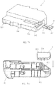
- FIG. 1 illustrates a perspective view of the alarming system for an wiper according to an embodiment of the invention
- Figure 2 illustrates an exploded view of the alarming system according to an embodiment of the invention.
- an alarming system for a wiper comprises a first connecting member 1 and a second connecting member 2.
- the first connecting member 1 is connected to the wiper arm 3
- the second connecting member 2 is connected to the wiper blade 4.
- the engagement between the wiper blade 4 and the wiper arm 3 is achieved by the engagement of the wiper blade adapter 41 and the wiper arm adapter 31.
- the wiper blade adapter 41 is snap-fitted into the wiper arm adapter 31 by pushing the wiper blade adapter 41 into the wiper arm adapter 31 along a long-axis direction of the wiper blade adapter 41, and thus the engagement of the wiper blade 4 with the wiper arm 3 is achieved.
- Figures 3, 4a and 4b respectively show enlarged views of the alarming system according to an embodiment of the invention.
- Figure 3 shows the case where the first connecting member 1 is not engaged with the second connecting member 2
- Figures 4a and 4b shows the case where the first connecting member 1 is engaged with the second connecting member 2.
- the first connection member 1 is located in the housing of the wiper arm adapter 31
- the second connection member 2 is located in the housing of the wiper blade adapter 41.
- Figure 5 illustrates an exploded view of the first connecting member 1 according to an embodiment of the invention
- Figure 6 illustrates a view of the first connecting member and wiper arm adapter 31 according to an embodiment of the invention.
- the first connecting member 1 comprises a first body 11 and a first number of first contacts 12 which are insulated to each other and disposed at the first body 11.
- the first contacts 12 are made of electrically conductive material, and the first body 11 is made of insulated material.
- the first number equals two, and the first number may also be selected as greater than two as required.
- the additional first contacts 12 may be used to be charged with electricity to heat liquid, such as cleaning fluid, in the wiper.
- two rod-shaped projections 111 are disposed on one side face of the first body 11, and the first contact elements 12 are respectively disposed on the outer surfaces of the rod-shaped projections 111.
- two cylindrical rod-shaped projections 111 project from one side face of the first body 11, and two first contacts 12 are nested on the ends of the two rod-shaped projections 111 respectively and are made of electrically conductive material, such as copper.
- the general shape of the first body 11 is adapted to be fixed in the housing of the wiper arm adapter 31.
- the first body 11 and the rod-shaped projections 111 may be of other shapes, respectively.
- the first contacts 12 may be provided at other positions of the outer wall of the rod-shaped projection 111, such as fully or partially cladding on the outer peripheral wall, or only disposed on the end surface.
- the first contacts 12 may be rod-shaped, which is connected to one side face of the first body 11. In the case where the first contacts 12 are rod-shaped, the first body 11 may not have the rod-shaped projections 111.
- the first connecting member 1 may further include a sealing gasket 13 disposed around the rod-shaped projection 111, and the sealing gasket 13 may be made of rubber material.
- the sealing gasket 13 is located between the first body 11 of the first connecting member 1 and the second body 21 of the second connection member 2 (the second body will be described in detail below) and seals therebetween.
- the first connecting member 1 further includes two parallel positioning walls 112 protruding from one side face of the first body 11, and a buckle 113 at the other side face of the first body 11.
- the wiper arm adapter 31 is provided with a positioning projection 311 and a snap groove 312. In this way, the first connecting member 1 can be snap-fitted into the housing of the wiper arm adapter 31.
- the first connecting member 1 When mounting the first connecting member 1 onto the wiper arm adapter 31, firstly the orientation of the first connecting member 1 is adjusted, and then the positioning wall 112 receives the positioning projection 311 and finally the first connecting member 1 is pressed into the housing of the wiper arm adapter 31 in the direction of the arrow shown in Figure 6 , such that the buckle 113 is received into the snap groove 312.
- the first connecting member 1 may also be fixed in the housing of the wiper arm adapter 31 in other manners, or the first connecting member may be connected to the wiper arm 3 other than the wiper arm adapter 31 in other ways. This other way is, for example, connecting by fasteners, adhering, welding, or the like.
- the first connecting member 1 may be connected to the wiper arm adapter 31 or other part of the wiper arm 3 through a flexible connection member such as a strap or a cord.
- Figures 7a , 7b illustrates an exploded view of the second connecting member 2 according to an embodiment of the invention, respectively.
- Figures 8a , 8b illustrates a view of the second connecting member 2 and wiper blade adapter 41 according to an embodiment of the invention, respectively.
- the second connecting member 2 comprises a second body 21 and a first number of second contacts 22 which are electrically connected to each other and disposed at the second body 21.
- the first number equals two.
- the second contacts 22 are made of an electrical conductive material, and the second body 21 is made of an insulated material.
- two grooves 211 which open towards a same direction are provided on one side face of the second body 21, two second contacts 22 are disposed in these two grooves 211 respectively, and the grooves 211 receive the rod-shaped projections 111.
- two cylindrical grooves 211 which open towards a same direction are provided on one side face surface of the second body 21, and are substantially complementary to the shapes of the two rod-shaped projections 111 of the first body 11, to allow the two grooves 211 to receive the two rod-shaped projections 111, respectively.
- the second contact 22 is sheet-shaped, and includes a attaching portion 221 atteched on the inner wall surface of the groove 211 and a press-contact portion 222 inclined to the central axis of the groove 211.
- the attaching portion 221 may be fixed on the inner wall surface of the groove 211 by pressing.
- the second contact 22 may also be in other shapes or be a coating, and may also be embedded in the inner wall of the groove 211 as long as at least one outer surface of the second contact 22 is exposed outwards.
- Two second contacts 22 may be integrally formed.
- the groove 211 is not limited to a hole shape and may be an open groove; the groove 211 is not limited to a cylindrical shape, and may be other shapes such as a cuboid.
- the second connecting member 2 may further include a sealing gasket mating groove 212 that is recessed inward from a side face which the opening of the groove 211 is towards.
- the shape of the second body 21 is adapted to be fixed in the housing of the wiper blade adapter 41.
- a first snap-fit structure 213 is also disposed on one side face of the second body 21, and a second snap-fit structure 411 which is mated with the first snap-fit structure 213 is disposed on the wiper blade adapter 41.
- the second body 21 is also provided with on the outer surface thereof a first positioning structure 214, and the wiper blade adapter 41 is provided with on the inner surface thereof a second positioning structure 412 that is mated with the first positioning structure 214, to facilitate the positioning and fixing of the second connecting member 2 in the housing of the wiper blade adapter 41.
- the second connecting member 2 can be snap-fitted into the housing of the wiper blade adapter 41.
- the orientation of the second connecting member 2 is adjusted, and then the second connecting member 2 is pressed into the housing of the wiper blade adapter 41 in the direction of the arrow shown in Figure 8a .
- the second connecting member 2 may be fixed in the housing of the wiper blade adapter 41 in other manners.
- the first connecting member 1 and the second connecting member 2 are snap-fitted in the housing of the wiper arm adapter 31 and the housing of the wiper blade adapter 41 respectively, the first connecting member 1 and the second connecting member 2 can be easily mounted and detached and can achieve appropriate fixing effects, which allows the first connecting member 1 and the second connecting member 2 to be selected by users as options and be replaced easily.
- Figure 9 illustrates the first connecting member 1 and the second connecting member 2 being connected together according to an embodiment of the invention.
- the first connecting member 1 is fixed in the housing of the wiper arm adapter 31, and the second connecting member 2 is fixed in the housing of the wiper blade adapter 41.
- said first connecting member 1 is connected to said second connecting member 2.
- the extending direction of the cylindrical rod-shaped projections 111 of the first body 11, the extending direction of the grooves 211 of the second body 21, the long axis direction of the wiper arm adapter 31, and the long axis direction of the wiper blade adapter 41 are same.
- the wiper blade adapter 41 is pushed into the wiper arm adapter 31 in the direction of the arrow shown in Figure 3 , while the first connecting member 1 is connected to the second connecting member 2, such that the two rod-shaped projections 111 are respectively inserted into the two grooves 211, resulting in that the two first contacts 12 located on the outer surfaces of the rod-shaped projections 111 are in contact with the two second contacts 22 located in the grooves 211 respectively.
- the first contacts 12 that are electrically insulated from each other establish electrical connection therebetween by means of the second contacts 22 that are electrically connected to each other.
- the press-contact portion 222 of the second contact 22 presses against the first contact 12, such that the first contact 12 and the second contact 22 can be in better contact, and the sealing gasket 13 is received into the sealing gasket mating grooves 212 and are subjected to a pressure perpendicular to the surface thereof, such that the space in which the first contacts 12 and the second contacts 22 are located is well sealed to prevent the entry of liquid and prevent electric leakage.
- connection between the first connecting member 1 and the second connecting member 2 may be fixed by the snap-fit member on the wiper arm adapter 41 and wiper arm adapter 31.
- corresponding snap-fit members may be provided on the first connecting member 1 and the second connecting member 2, to fix the connection between the first connecting member 1 and the second connecting member 2.
- the snap-fit members can apply pressure to the sealing gasket 13 in a direction perpendicular to its surface.
- the wiper arm 3 and the wiper blade 4 of the motor vehicle are connected by a wiper arm adapter 31, which is typically located at the end of the wiper arm 3, and a wiper blade adapter 41, which is located near the mid-portion of the wiper blade 4, such that the wiper arm 3 drives the wiper blade 4 to swing back and forth.
- the wiper blade adapter 41 of the motor vehicle and the wiper arm adapter 31 corresponding thereto may be of various types.
- the direct insertion connection is used as an example for illustration, but is not limited thereto.
- the first connecting member 1 may be coupled with the second connecting member 2, for example, the first connecting member 1 may be inserted into the second connecting member 2 from one side, after assembling the wiper blade 4 to the wiper arm 3, that is, after assembling the wiper blade adapter 41 to the wiper arm adapter 31.
- the first connecting member 1 and the second connecting member 2 may be connected to the wiper arm 3 and the wiper blade 4 respectively in various ways, for example, the first connecting member 1 or the second connecting member 2 respectively does not necessarily be fixed in the housing of the wiper arm adapter 31 or the housing of the wiper blade adapter 41, and the mounting way and mounting sequence thereof may also be modified, as long as when the wiper blade 4 is properly mounted to the wiper arm 3, the first connecting member 1 is connected with the second connecting member 2 (not necessarily simultaneously), such that each of the first contacts 12 is in contact with the corresponding second contact respectively, and thus the first contacts 12 are electrically connected to each other through the second contacts 22.
- the alarming system for the wiper may further include a control member (not shown in the figures), which is configured to sense the electrical connection between the first contacts 12, and to generate an alarm signal when the electrical connection between the first contacts 12 is disconnected.
- the control member may be located at the body of the vehicle, and specifically, the control member may be included in ECU of the vehicle. As shown in Figure 2 , the first connecting member 1 is connected to the corresponding inputs of the ECU by signal lines 5. Since the wiper arm 3 is moved at the time of operation, at least a part of the signal line 5 extends along the wiper arm 3 and is fixed to the wiper arm 3, in order to prevent the signal line 5 from being wound or damaged.
- Figure 10 illustrates a view of the wiper arm 3 and the signal line retaining clip 6 according to an embodiment of the invention.
- Figure 11 illustrates a perspective view of the signal line retaining clip 6 according to an embodiment of the invention.
- the signal line 5 can be fixed to the wiper arm 3 by the signal line retaining clip 6.
- the signal line retaining clip 6 is substantially an annular structure having an opening 61, and the signal line retaining clip 6 further includes a recess 62 that protrudes outward.
- the signal line retaining clip 6 has elasticity, its opening can be temporarily expanded.
- the signal line retaining clip 6 can be nested on the wiper arm 3 from the direction shown in Figure 10 , and the signal line 5 is fixed in the recess 62.
- the signal line 5 may also be located in the interior cavity of the wiper arm 3.
- the first connecting member 1 and the second connecting member 2 are connected so that each of the first contacts 12 is respectively in contact with the corresponding second contact, thereby the two first contacts that are insulated from each other establish electrical connection therebetween by two second contacts 22 that are electrically connected to each other.
- the first connecting member 1 is connected to the wiper arm 3 and the second connecting member 2 is connected to the wiper blade 4 (specifically, for example, the first connecting member 1 is fixed in the housing of the wiper arm adapter 31, and the second connecting member 2 is fixed in the housing of the wiper blade adapter 41), the first connecting member 1 is not removed together with the wiper blade 4, while the second connecting member 2 is removed together with the wiper blade 4. In this way, the first connecting member 1 is no longer connected with the second connecting member 2, thereby causing the electrical connection between the two first contacts 12 through the second contact 22 to be disconnected.
- the control member senses that the electrical connection between the two first contacts 12 is disconnected, an alarm signal is generated.
- the control member includes the ECU, the ECU generates an alarm signal, and may control the alarm of the vehicle to generate a sound, and may also control the camera on the motor vehicle to capture the image around the motor vehicle.
- the control member may also be configured to send alarm information to alarm information receiver.
- the alarm information receiver may be a mobile terminal, for example, a user's smart phone, tablet computer, laptop computer and the like.
- the alarm information receiver can also be a computer, a server, etc., and the server can further push related alarm information to the user. In this way, the user can instantly know the abnormal condition of the wiper blade 4 on the wiper.
- the mobile terminal After the mobile terminal receives the alarm information, it can receive the image(s) captured by the camera to view the situation around the motor vehicle, or can turn off the alarm, and so on.
- the alarming system can also monitor whether the wiper blade 4 is properly mounted on the wiper arm 3. For example, in the embodiment shown in Figure 3 , if the wiper blade 4 is not properly mounted on the wiper arm 3, the first contact 12 and the second contact 22 can not contact well, resulting in a disconnection of the electrical connection between the first contacts 12, and further causing the control member to generate an alarm signal.
- Figure 12 illustrates an exploded view of the first connecting member 1 according to another embodiment of the invention.
- the alarming system further comprises a wireless transmitting member positioned in the first body 11 and a wireless receiving member coupled to the control member.
- the wireless receiving member may be included in the control member.
- the control member may be configured to sense the electrical connection between the first contacts 12 via the wireless transmitting member and the wireless receiving member.
- the first contacts 12 may be electrically connected to respective inputs of the wireless transmitting member, and the wireless transmitting member and the wireless receiving member may communicate via protocols such as Bluetooth, ZigBee, NFC, and the like.
- the wireless transmitting member sends a signal to the wireless receiving member when the electrical connection between the first contacts 12 is disconnected.
- the wireless receiving member then sends a signal to the control member if the wireless receiving member is a member independent of the control member, and in this way, the control member senses the disconnection of the electrical connection between the first contacts 12, thereby generating an alarm signal. If the wireless receiving member is included in the control member, the control member directly receives the transmitted signal sent from the wireless transmitting member, and in this way, the control member senses the disconnection of the electrical connection between the first contacts 12, thereby generating an alarm signal.
- the wireless transmitting member may include a battery 71 for supplying power.
- the battery 71 is a button battery, and a battery space 72 for accommodating the battery 71 is provided in the first body 11.
- a seal ring 73 and a battery cap 74 for enclosing the battery space 72 are provided above the battery 71.
- the battery cap 74 is provided with a radial projection 741 on an outer periphery thereof, and the battery space 72 is provided with a radial groove 721 mated with the radial projection 741 and a mounting opening 722 that has a shape mated with the shape of the radial projection 741.
- a battery cap 74 is placed in the mounting opening 722, the battery cap 74 is rotated, such that the battery cap 74 is snap-fitted into the radial groove 721, and a vertical direction force is applied to the seal ring 73 to seal the battery space 72.
- the wireless transmitting component and the wireless receiving component may be, for example, a Bluetooth transmitting member and a Bluetooth receiving member.
- the first connecting member 1 may also be connected to the wiper blade 4, and the second connecting member 2 may be connected to the wiper arm 3.
- first connecting member 1 and the second connecting member 2 may be in other configurations.
- the first body 11 is provided with a first number of grooves that open in a same direction, and the first contacts 12 are disposed in the first number of grooves respectively.
- the second body 21 is provided with on one side face thereof a first number of rod-shaped projections, the second contacts 22 are disposed on outer surfaces of the first number of rod-shaped projections, and said grooves receive said rod-shaped projections.
- the first body 11 is provided with a first number of grooves that open in a same direction, and the first contacts 12 are disposed in the first number of grooves respectively.
- the second contacts 22 are rod-shaped and are connected to one side face of the second body 21, and the grooves receive the rod-shaped second contacts 22.
- the first body 11 and the second body 21 are respectively provided with complementary-shaped portions that are mutually received, so that the first contacts 12 are respectively in contact with the second contacts 22.
- the complementary-shaped portions may not be limited to receive each other by means of plugging.
- a wiper blade assembly with an alarming function according to the invention is described below.
- the wiper blade assembly with an alarming function includes a wiper blade 4, a wiper blade adapter 41, and a second connecting member 2.
- the second connecting member may be fixed in a housing of said wiper blade adapter 41, and comprises a second body 21 and a first number of second contacts 22 which are disposed at the second body 21 and are electrically connected to each other.
- the first number equals 2.
- the first number may be greater than two.
- the second contacts 22 may be made of an electrical conductive material, and the second body 21 may be made of an insulated material.
- two grooves 211 which open towards a same direction are provided on one side face of the second body 21, and two second contacts 22 are disposed in the two grooves respectively.
- two rod-shaped projections may be provided on one side face of the second body 21, and two second contacts 22 may be disposed on the outer surfaces of the two rod-shaped projections respectively.
- the second contacts 22 may be rod-shaped and be connected to one side face of the second body 21.
- the wiper blade assembly with an alarming function includes a wiper blade 4, a wiper blade adapter 41, a first connecting member 1 and a wireless transmitting member.
- the first connecting member is fixed in a housing of the wiper blade adapter 41, and comprises a first body 11 and two first contacts 12 which are disposed at the first body 11 and are electrically insulated to each other.
- the wireless transmitting member is located in the first body 11, and the first contacts 12 are electrically connected to corresponding inputs of the wireless transmitting member respectively.
- the first contacts 12 are made of an electrical conductive material, and the first body 11 is made of an insulated material.
- two rod-shaped projections are provided on one side face of the first body 11, and two first contacts 12 are disposed on the outer surfaces of the two rod-shaped projections respectively.
- the first contacts 12 may be rod-shaped and be connected to one side face of the first body 11.
- two grooves which open towards a same direction may be provided on one side face of the first body 11, and the first contacts 12 are disposed in the two grooves respectively.
Abstract
Description
- The invention relates to an alarming system, and in particular, to an alarming system for a wiper of a motor vehicle. The invention also relates to a wiper blade assembly, and in particular to a wiper blade assembly with alarming function.
- Motor vehicles are usually equipped with a wiper system, which is used to clean the windshield. Traditional wiper system generally includes a wiper blade, a wiper arm, and transmissions. The wiper arm is driven by the transmission to perform a swing motion, driving the wiper blade to move in conjunction. The wiper blade wipes the windshield and removes foreign objects on the windshield out of the driver's field of vision.
- Generally, the wiper blade and the wiper arm are detachably connected together by a wiper arm adapter provided at one end of the wiper arm and a wiper blade adapter provided on the wiper blade. In order to facilitate the replacement of the wiper blade, the connection is usually simple and easily detached, with the result that the wiper blade being easily stolen. In addition, installation errors between the wiper arm and the wiper blade may sometimes occur due to a careless installation. Therefore, there is a need for an alarming system and a wiper blade with an alarming function to alarm the stealing or improper installation of the wiper blade.
- In order to solve the problems in the prior art, it is an object of the present invention to provide an alarming system for a wiper, which can be used to issue an alarm when a wiper blade is stolen or improperly mounted.
- An alarming system for a wiper comprises: a first connecting member comprising a first body and a first number of first contacts which are insulated to each other and disposed at the first body; a second connecting member comprising a second body and a first number of second contacts which are electrically connected to each other and disposed at the second body; and control member; wherein any one of the first connecting member or the second connecting member is connected to a wiper arm; the other one of the first connecting member or the second connecting member is connected to a wiper blade; the first contacts and the second contacts are made of conductive material, the first body and the second body are made of insulated material, the first number is equal to or larger than two; when the wiper blade is properly mounted to the wiper arm, the first connecting member is connected with the second connecting member, such that each of the first contacts is in contact with corresponding one of the second contacts, and thereby the first number of the first contacts are electrically connected to each other through the first number of the second contacts; and the control member is configured to sense the electrical connection between the first contacts, and to generate alarm signal when the electrical connection between the first contacts is disconnected.
- Preferably, the control member is configured to send an alarm information to an alarm information receiver.
- Preferably, the alarm information receiver is a mobile terminal.
- Preferably, the control member is configured to control a camera of a vehicle to capture images surrounding the vehicle or to ring the alarm of the vehicle after generating the alarm signal.
- Preferably, the control member is located at a body of the vehicle.
- Preferably, the control member is included in an electronic control unit of the vehicle.
- Preferably, the one of the first connecting member and the second connecting member which is connected to the wiper arm is the first connecting member, the first contacts are connected to the corresponding inputs of the control member through signal lines respectively, and at least a portion of the signal lines extend along the wiper arm and are fixed to the wiper arm.
- Preferably, the alarming system further comprises a wireless transmitting member and a wireless receiving member; the control member is configured to sense the electrical connection between the first contacts by the wireless transmitting member and the wireless receiving member, the wireless transmitting member is located in the first body, the first contacts are electrically connected to the corresponding inputs of the wireless transmitting member respectively, the control member is coupled to the wireless receiving member or comprises the wireless receiving member.
- Preferably, the second body is provided with on one side face thereof a first number of grooves which are open towards a same direction, and the first number of the second contacts are disposed in the first number of grooves respectively.
- Preferably, the first body is provided with on one side face thereof a first number of rod-shaped projections, the first number of first contacts are disposed on outer surfaces of the first number of rod-shaped projections respectively; and the grooves receive the rod-shaped projections.
- Preferably, the first contacts are of rod shape, and are connected to one side face of the first body; and the grooves receive the first contacts.
- Preferably, the other one of the first connecting member and the second connecting member is connected to wiper blade adapter, and the extending direction of the grooves is in consistent with the longitudinal axis of the wiper blade adapter.
- Preferably, the first body is provided with on one side face thereof a first number of grooves which are open towards a same direction, and the first number of the first contacts are disposed in the first number of grooves respectively.
- Preferably, the second body is provided with on one side face thereof a first number of rod-shaped projections, the first number of second contacts are disposed on outer surfaces of the first number of rod-shaped projections respectively; and the grooves receive the rod-shaped projections.
- Preferably, the second contacts are of rod shape, and are connected to one side face of the second body; and the grooves receive the second contacts.
- Preferably, the other one of the first connecting member and the second connecting member is connected to wiper blade adapter, and the extending direction of the grooves is in consistent with the longitudinal axis of the wiper blade adapter.
- Preferably, the other one of the first connecting member and the second connecting member is snap-fitted in the housing of the wiper blade adapter.
- Preferably, the one of the first connecting member and the second connecting member is snap-fitted in the housing of the wiper arm adapter.
- Preferably, the one of the first connecting member and the second connecting member is connected to the wiper arm by a flexible connecting member.
- Preferably, while the wiper blade adapter is properly mounted to wiper arm adapter, the first connecting member is connected to the second connecting member.
- Preferably, the first number of second contacts are formed in one piece.
- Preferably, the first body is formed integral with a wiper arm adapter, the second body is formed integral with a wiper blade adapter.
- An further object of the invention is to provide a wiper blade assembly with a alarming function, which comprises: a wiper blade, a wiper blade adapter, and a second connecting memberfixed in a housing of the wiper blade adapter and comprising a second body and a first number of second contacts which are disposed in the second body and are electrically connected to each other; wherein the second contacts are made of conductive material, the second body is made of insulated material, the first number is equal to or larger than two.
- Preferably, the second body is provided with on one side face thereof a first number of grooves which are open towards a same direction, and the first number of the second contacts are disposed in the first number of grooves respectively.
- Preferably, the second body is provided with on one side thereof a first number of rod-shaped projections, and the first number of second contacts are disposed on outer surfaces of the first number of rod-shaped projections respectively.
- Preferably, the second contacts are of rod shape, and are connected to one side face of the second body.
- The invention further provides a wiper blade assembly with a alarming function, which comprises: a wiper blade, a wiper blade adapter, and a first connecting member fixed in a housing of the wiper blade adapter and comprising a first body and a first number of first contacts which are disposed in the first body and are electrically insulated to each other; and wireless transmitting member, located in the first body, the first contacts electrically connected to corresponding inputs of the wireless transmitting member respectively; wherein the first contact are made of conductive material, the first body is made of insulated material, the first number is equal to or larger than two.
- Preferably, the first body is provided with on one side face thereof a first number of rod-shaped projections, the first number of first contacts are disposed on outer surfaces of the first number of rod-shaped projections respectively.
- Preferably, the first contacts are of rod shape, and are connected onto one side face of the first body.
- Preferably, the first body is provided with on one side face thereof a first number of grooves which are open towards a same direction, and the first number of the first contacts are disposed in the first number of grooves respectively.
- In order to explain the technical solutions of the embodiments of the present invention more clearly, the drawings used in the embodiments will be briefly described below. It should be understood that, the following drawings merely illustrate some embodiments of the present invention and therefore should not be regarded as a limitation of the protective scope. For those skilled in the art, other related drawings may also be obtained based on these drawings without any creative effort.
-
Figure 1 illustrates a perspective view of the alarming system according to an embodiment of the invention; -
Figure 2 illustrates an exploded view of the alarming system according to an embodiment of the invention; -
Figure 3 illustrates an enlarge view of the alarming system according to an embodiment of the invention, in which the first connecting member is not engaged with the second connecting member; -
Figure 4a illustrates an enlarge view of the alarming system according to an embodiment of the invention, in which the first connecting member is engaged with the second connecting member; -
Figure 4b illustrates a view of the alarming system ofFigure 4a from another perspective; -
Figure 5 illustrates an exploded view of the first connecting member according to an embodiment of the invention; -
Figure 6 illustrates a view of the first connecting member and wiper arm adapter according to an embodiment of the invention; -
Figure 7a illustrates a perspective view of the second connecting member according to an embodiment of the invention; -
Figure 7b illustrates an exploded view of the second connecting member according to an embodiment of the invention; -
Figure 8a illustrates a view of the second connecting member and wiper blade adapter according to an embodiment of the invention; -
Figure 8b illustrates another view of the second connecting member and wiper blade adapter according to an embodiment of the invention; -
Figure 9 illustrates a vew showing the first connecting member and the second connecting member being connected together according to an embodiment of the invention; -
Figure 10 illustrates a view of the wiper arm and the signal line retaining clip according to an embodiment of the invention; -
Figure 11 illustrates a perspective view of the line signal retaining clip according to an embodiment of the invention; -
Figure 12 illustrates an exploded view of the first connecting member according to another embodiment of the invention. - Hereinafter, the alarming system according to an embodiment of the invention will be described in detail with reference to the accompanying drawings. To make the objectives, the technical solutions, and the advantages of the embodiments of the present invention clearer, the following describes the technical solutions in the embodiments of the present invention clearly and comprehensively in conjunction with the accompanying drawings of the embodiments of the present invention. Obviously, the described embodiments are only a portion of the embodiments of the present invention, not all of the embodiments.
- Thus, the following detailed description of embodiments of the invention, as provided in conjunction with the accompanying drawings, is not intended to limit the scope of the invention as claimed, but is merely representative of selected embodiments of the invention. All other embodiments obtained by a person of ordinary skill in the art based on the embodiments of the present invention without creative efforts shall fall within the protection scope of the present invention.
- In the description of the invention, it should be understood that the connection between one part and another part is not limited to direct connection but may also be connection through other parts.
- In the following description, numerous specific details are set forth to provide a thorough understanding of the embodiments. However, those skilled in the relevant art will recognize that the techniques described herein may be practiced without one or more of the specific details or through other methods, components, materials, or the like. In other instances, well-known structures, materials, or operations are not shown or described in detail to avoid obscuring aspects. In addition, certain features, structures may be combined in any suitable manner in one or more embodiments.
-
Figure 1 illustrates a perspective view of the alarming system for an wiper according to an embodiment of the invention, andFigure 2 illustrates an exploded view of the alarming system according to an embodiment of the invention. As shown inFigures 1 and 2 , an alarming system for a wiper comprises a first connectingmember 1 and a second connectingmember 2. In this embodiment, the first connectingmember 1 is connected to thewiper arm 3, and the second connectingmember 2 is connected to the wiper blade 4. The engagement between the wiper blade 4 and thewiper arm 3 is achieved by the engagement of thewiper blade adapter 41 and thewiper arm adapter 31. In this embodiment, thewiper blade adapter 41 is snap-fitted into thewiper arm adapter 31 by pushing thewiper blade adapter 41 into thewiper arm adapter 31 along a long-axis direction of thewiper blade adapter 41, and thus the engagement of the wiper blade 4 with thewiper arm 3 is achieved. -
Figures 3, 4a and4b respectively show enlarged views of the alarming system according to an embodiment of the invention. In the figures, for clarity, only thewiper blade adapter 41 and thewiper arm adapter 31 are shown.Figure 3 shows the case where the first connectingmember 1 is not engaged with the second connectingmember 2, andFigures 4a and4b shows the case where the first connectingmember 1 is engaged with the second connectingmember 2. Specifically, as shown inFIGS. 3, 4a and4b , in this embodiment, thefirst connection member 1 is located in the housing of thewiper arm adapter 31, and thesecond connection member 2 is located in the housing of thewiper blade adapter 41. -
Figure 5 illustrates an exploded view of the first connectingmember 1 according to an embodiment of the invention, andFigure 6 illustrates a view of the first connecting member andwiper arm adapter 31 according to an embodiment of the invention. - As shown in
Figure 5 , the first connectingmember 1 comprises afirst body 11 and a first number offirst contacts 12 which are insulated to each other and disposed at thefirst body 11. Thefirst contacts 12 are made of electrically conductive material, and thefirst body 11 is made of insulated material. In this embodiment, the first number equals two, and the first number may also be selected as greater than two as required. For example, when the first number is greater than two, the additionalfirst contacts 12 may be used to be charged with electricity to heat liquid, such as cleaning fluid, in the wiper. - As shown in
FIG. 5 , in this embodiment, two rod-shapedprojections 111 are disposed on one side face of thefirst body 11, and thefirst contact elements 12 are respectively disposed on the outer surfaces of the rod-shapedprojections 111. Specifically, two cylindrical rod-shapedprojections 111 project from one side face of thefirst body 11, and twofirst contacts 12 are nested on the ends of the two rod-shapedprojections 111 respectively and are made of electrically conductive material, such as copper. Specifically, the general shape of thefirst body 11 is adapted to be fixed in the housing of thewiper arm adapter 31. Alternatively, thefirst body 11 and the rod-shapedprojections 111 may be of other shapes, respectively. Alternatively, thefirst contacts 12 may be provided at other positions of the outer wall of the rod-shapedprojection 111, such as fully or partially cladding on the outer peripheral wall, or only disposed on the end surface. For example, in other embodiments, thefirst contacts 12 may be rod-shaped, which is connected to one side face of thefirst body 11. In the case where thefirst contacts 12 are rod-shaped, thefirst body 11 may not have the rod-shapedprojections 111. - As shown in
FIG. 5 , the first connectingmember 1 may further include a sealinggasket 13 disposed around the rod-shapedprojection 111, and the sealinggasket 13 may be made of rubber material. When the first connectingmember 1 and the second connectingmember 2 are connected, the sealinggasket 13 is located between thefirst body 11 of the first connectingmember 1 and thesecond body 21 of the second connection member 2 (the second body will be described in detail below) and seals therebetween. - As shown in
FIG. 6 , in this embodiment, the first connectingmember 1 further includes twoparallel positioning walls 112 protruding from one side face of thefirst body 11, and abuckle 113 at the other side face of thefirst body 11. Correspondingly, thewiper arm adapter 31 is provided with apositioning projection 311 and asnap groove 312. In this way, the first connectingmember 1 can be snap-fitted into the housing of thewiper arm adapter 31. When mounting the first connectingmember 1 onto thewiper arm adapter 31, firstly the orientation of the first connectingmember 1 is adjusted, and then thepositioning wall 112 receives thepositioning projection 311 and finally the first connectingmember 1 is pressed into the housing of thewiper arm adapter 31 in the direction of the arrow shown inFigure 6 , such that thebuckle 113 is received into thesnap groove 312. In other embodiments, the first connectingmember 1 may also be fixed in the housing of thewiper arm adapter 31 in other manners, or the first connecting member may be connected to thewiper arm 3 other than thewiper arm adapter 31 in other ways. This other way is, for example, connecting by fasteners, adhering, welding, or the like. In addition, the first connectingmember 1 may be connected to thewiper arm adapter 31 or other part of thewiper arm 3 through a flexible connection member such as a strap or a cord. -
Figures 7a ,7b illustrates an exploded view of the second connectingmember 2 according to an embodiment of the invention, respectively.Figures 8a ,8b illustrates a view of the second connectingmember 2 andwiper blade adapter 41 according to an embodiment of the invention, respectively. - As shown in
Figures 7a and7b , the second connectingmember 2 comprises asecond body 21 and a first number ofsecond contacts 22 which are electrically connected to each other and disposed at thesecond body 21. In this embodiment, the first number equals two. Thesecond contacts 22 are made of an electrical conductive material, and thesecond body 21 is made of an insulated material. In this embodiment, twogrooves 211 which open towards a same direction are provided on one side face of thesecond body 21, twosecond contacts 22 are disposed in these twogrooves 211 respectively, and thegrooves 211 receive the rod-shapedprojections 111. Specifically, twocylindrical grooves 211 which open towards a same direction are provided on one side face surface of thesecond body 21, and are substantially complementary to the shapes of the two rod-shapedprojections 111 of thefirst body 11, to allow the twogrooves 211 to receive the two rod-shapedprojections 111, respectively. Specifically, thesecond contact 22 is sheet-shaped, and includes a attachingportion 221 atteched on the inner wall surface of thegroove 211 and a press-contact portion 222 inclined to the central axis of thegroove 211. The attachingportion 221 may be fixed on the inner wall surface of thegroove 211 by pressing. Alternatively, thesecond contact 22 may also be in other shapes or be a coating, and may also be embedded in the inner wall of thegroove 211 as long as at least one outer surface of thesecond contact 22 is exposed outwards. Twosecond contacts 22 may be integrally formed. Alternatively, thegroove 211 is not limited to a hole shape and may be an open groove; thegroove 211 is not limited to a cylindrical shape, and may be other shapes such as a cuboid. - As shown in
Figures 7a and7b , the second connectingmember 2 may further include a sealinggasket mating groove 212 that is recessed inward from a side face which the opening of thegroove 211 is towards. - As shown in
Figures 8a and8b , the shape of thesecond body 21 is adapted to be fixed in the housing of thewiper blade adapter 41. A first snap-fit structure 213 is also disposed on one side face of thesecond body 21, and a second snap-fit structure 411 which is mated with the first snap-fit structure 213 is disposed on thewiper blade adapter 41. In addition, thesecond body 21 is also provided with on the outer surface thereof afirst positioning structure 214, and thewiper blade adapter 41 is provided with on the inner surface thereof asecond positioning structure 412 that is mated with thefirst positioning structure 214, to facilitate the positioning and fixing of the second connectingmember 2 in the housing of thewiper blade adapter 41. The second connectingmember 2 can be snap-fitted into the housing of thewiper blade adapter 41. When mounting the second connectingmember 2 onto thewiper blade adapter 41, firstly the orientation of the second connectingmember 2 is adjusted, and then the second connectingmember 2 is pressed into the housing of thewiper blade adapter 41 in the direction of the arrow shown inFigure 8a . In other embodiments, the second connectingmember 2 may be fixed in the housing of thewiper blade adapter 41 in other manners. - In this embodiment, as the first connecting
member 1 and the second connectingmember 2 are snap-fitted in the housing of thewiper arm adapter 31 and the housing of thewiper blade adapter 41 respectively, the first connectingmember 1 and the second connectingmember 2 can be easily mounted and detached and can achieve appropriate fixing effects, which allows the first connectingmember 1 and the second connectingmember 2 to be selected by users as options and be replaced easily. -
Figure 9 illustrates the first connectingmember 1 and the second connectingmember 2 being connected together according to an embodiment of the invention. Referring toFigures 3 and9 , the first connectingmember 1 is fixed in the housing of thewiper arm adapter 31, and the second connectingmember 2 is fixed in the housing of thewiper blade adapter 41. When thewiper blade adapter 41 is properly mounted towiper arm adapter 31, said first connectingmember 1 is connected to said second connectingmember 2. Specifically, the extending direction of the cylindrical rod-shapedprojections 111 of thefirst body 11, the extending direction of thegrooves 211 of thesecond body 21, the long axis direction of thewiper arm adapter 31, and the long axis direction of thewiper blade adapter 41 are same. In this embodiment, as shown inFigure 3 , thewiper blade adapter 41 is pushed into thewiper arm adapter 31 in the direction of the arrow shown inFigure 3 , while the first connectingmember 1 is connected to the second connectingmember 2, such that the two rod-shapedprojections 111 are respectively inserted into the twogrooves 211, resulting in that the twofirst contacts 12 located on the outer surfaces of the rod-shapedprojections 111 are in contact with the twosecond contacts 22 located in thegrooves 211 respectively. In this way, thefirst contacts 12 that are electrically insulated from each other establish electrical connection therebetween by means of thesecond contacts 22 that are electrically connected to each other. Advantageously, the press-contact portion 222 of thesecond contact 22 presses against thefirst contact 12, such that thefirst contact 12 and thesecond contact 22 can be in better contact, and the sealinggasket 13 is received into the sealinggasket mating grooves 212 and are subjected to a pressure perpendicular to the surface thereof, such that the space in which thefirst contacts 12 and thesecond contacts 22 are located is well sealed to prevent the entry of liquid and prevent electric leakage. - In this embodiment, the connection between the first connecting
member 1 and the second connectingmember 2 may be fixed by the snap-fit member on thewiper arm adapter 41 andwiper arm adapter 31. In addition, corresponding snap-fit members may be provided on the first connectingmember 1 and the second connectingmember 2, to fix the connection between the first connectingmember 1 and the second connectingmember 2. The snap-fit members can apply pressure to the sealinggasket 13 in a direction perpendicular to its surface. - The
wiper arm 3 and the wiper blade 4 of the motor vehicle are connected by awiper arm adapter 31, which is typically located at the end of thewiper arm 3, and awiper blade adapter 41, which is located near the mid-portion of the wiper blade 4, such that thewiper arm 3 drives the wiper blade 4 to swing back and forth. Thewiper blade adapter 41 of the motor vehicle and thewiper arm adapter 31 corresponding thereto may be of various types. Herein, the direct insertion connection is used as an example for illustration, but is not limited thereto. - In some cases where the first connecting
member 1 is connected to thewiper arm 3 by other means, the first connectingmember 1 may be coupled with the second connectingmember 2, for example, the first connectingmember 1 may be inserted into the second connectingmember 2 from one side, after assembling the wiper blade 4 to thewiper arm 3, that is, after assembling thewiper blade adapter 41 to thewiper arm adapter 31. For thewiper arm 3 and the wiper blade 4 which are assembled in other forms, the first connectingmember 1 and the second connectingmember 2 may be connected to thewiper arm 3 and the wiper blade 4 respectively in various ways, for example, the first connectingmember 1 or the second connectingmember 2 respectively does not necessarily be fixed in the housing of thewiper arm adapter 31 or the housing of thewiper blade adapter 41, and the mounting way and mounting sequence thereof may also be modified, as long as when the wiper blade 4 is properly mounted to thewiper arm 3, the first connectingmember 1 is connected with the second connecting member 2 (not necessarily simultaneously), such that each of thefirst contacts 12 is in contact with the corresponding second contact respectively, and thus thefirst contacts 12 are electrically connected to each other through thesecond contacts 22. - The alarming system for the wiper may further include a control member (not shown in the figures), which is configured to sense the electrical connection between the
first contacts 12, and to generate an alarm signal when the electrical connection between thefirst contacts 12 is disconnected. - The control member may be located at the body of the vehicle, and specifically, the control member may be included in ECU of the vehicle. As shown in
Figure 2 , the first connectingmember 1 is connected to the corresponding inputs of the ECU bysignal lines 5. Since thewiper arm 3 is moved at the time of operation, at least a part of thesignal line 5 extends along thewiper arm 3 and is fixed to thewiper arm 3, in order to prevent thesignal line 5 from being wound or damaged. -
Figure 10 illustrates a view of thewiper arm 3 and the signalline retaining clip 6 according to an embodiment of the invention.Figure 11 illustrates a perspective view of the signalline retaining clip 6 according to an embodiment of the invention. As shown inFigure 10 , thesignal line 5 can be fixed to thewiper arm 3 by the signalline retaining clip 6. As shown inFigure 11 , the signalline retaining clip 6 is substantially an annular structure having anopening 61, and the signalline retaining clip 6 further includes arecess 62 that protrudes outward. As shown inFigure 10 , the signalline retaining clip 6 has elasticity, its opening can be temporarily expanded. The signalline retaining clip 6 can be nested on thewiper arm 3 from the direction shown inFigure 10 , and thesignal line 5 is fixed in therecess 62. Alternatively, thesignal line 5 may also be located in the interior cavity of thewiper arm 3. - As described above, when the wiper blade 4 is properly mounted to the
wiper arm 3, the first connectingmember 1 and the second connectingmember 2 are connected so that each of thefirst contacts 12 is respectively in contact with the corresponding second contact, thereby the two first contacts that are insulated from each other establish electrical connection therebetween by twosecond contacts 22 that are electrically connected to each other. - When the wiper blade 4 is detached from the
wiper arm 3, for example when it is stolen, since the first connectingmember 1 is connected to thewiper arm 3 and the second connectingmember 2 is connected to the wiper blade 4 (specifically, for example, the first connectingmember 1 is fixed in the housing of thewiper arm adapter 31, and the second connectingmember 2 is fixed in the housing of the wiper blade adapter 41), the first connectingmember 1 is not removed together with the wiper blade 4, while the second connectingmember 2 is removed together with the wiper blade 4. In this way, the first connectingmember 1 is no longer connected with the second connectingmember 2, thereby causing the electrical connection between the twofirst contacts 12 through thesecond contact 22 to be disconnected. After the control member senses that the electrical connection between the twofirst contacts 12 is disconnected, an alarm signal is generated. Here, the control member includes the ECU, the ECU generates an alarm signal, and may control the alarm of the vehicle to generate a sound, and may also control the camera on the motor vehicle to capture the image around the motor vehicle. - The control member may also be configured to send alarm information to alarm information receiver. The alarm information receiver may be a mobile terminal, for example, a user's smart phone, tablet computer, laptop computer and the like. The alarm information receiver can also be a computer, a server, etc., and the server can further push related alarm information to the user. In this way, the user can instantly know the abnormal condition of the wiper blade 4 on the wiper. After the mobile terminal receives the alarm information, it can receive the image(s) captured by the camera to view the situation around the motor vehicle, or can turn off the alarm, and so on.
- The alarming system can also monitor whether the wiper blade 4 is properly mounted on the
wiper arm 3. For example, in the embodiment shown inFigure 3 , if the wiper blade 4 is not properly mounted on thewiper arm 3, thefirst contact 12 and thesecond contact 22 can not contact well, resulting in a disconnection of the electrical connection between thefirst contacts 12, and further causing the control member to generate an alarm signal. -
Figure 12 illustrates an exploded view of the first connectingmember 1 according to another embodiment of the invention. As shown inFigure 12 , the alarming system further comprises a wireless transmitting member positioned in thefirst body 11 and a wireless receiving member coupled to the control member. The wireless receiving member may be included in the control member. The control member may be configured to sense the electrical connection between thefirst contacts 12 via the wireless transmitting member and the wireless receiving member. Thefirst contacts 12 may be electrically connected to respective inputs of the wireless transmitting member, and the wireless transmitting member and the wireless receiving member may communicate via protocols such as Bluetooth, ZigBee, NFC, and the like. Specifically, the wireless transmitting member sends a signal to the wireless receiving member when the electrical connection between thefirst contacts 12 is disconnected. The wireless receiving member then sends a signal to the control member if the wireless receiving member is a member independent of the control member, and in this way, the control member senses the disconnection of the electrical connection between thefirst contacts 12, thereby generating an alarm signal. If the wireless receiving member is included in the control member, the control member directly receives the transmitted signal sent from the wireless transmitting member, and in this way, the control member senses the disconnection of the electrical connection between thefirst contacts 12, thereby generating an alarm signal. - The wireless transmitting member may include a
battery 71 for supplying power. As shown inFigure 12 , thebattery 71 is a button battery, and abattery space 72 for accommodating thebattery 71 is provided in thefirst body 11. In addition, aseal ring 73 and abattery cap 74 for enclosing thebattery space 72 are provided above thebattery 71. Thebattery cap 74 is provided with aradial projection 741 on an outer periphery thereof, and thebattery space 72 is provided with aradial groove 721 mated with theradial projection 741 and a mountingopening 722 that has a shape mated with the shape of theradial projection 741. Abattery cap 74 is placed in the mountingopening 722, thebattery cap 74 is rotated, such that thebattery cap 74 is snap-fitted into theradial groove 721, and a vertical direction force is applied to theseal ring 73 to seal thebattery space 72. The wireless transmitting component and the wireless receiving component may be, for example, a Bluetooth transmitting member and a Bluetooth receiving member. - In other embodiments, if the first connecting
member 1 does not need to be connected to the control member on the vehicle body in a wired manner, for example, if the control member senses the connection between thefirst contact 12 through the wireless transmission member and the wireless receiving member, the first connectingmember 1 may also be connected to the wiper blade 4, and the second connectingmember 2 may be connected to thewiper arm 3. - In other embodiments, the first connecting
member 1 and the second connectingmember 2 may be in other configurations. - For example, in an embodiment, the
first body 11 is provided with a first number of grooves that open in a same direction, and thefirst contacts 12 are disposed in the first number of grooves respectively. Thesecond body 21 is provided with on one side face thereof a first number of rod-shaped projections, thesecond contacts 22 are disposed on outer surfaces of the first number of rod-shaped projections, and said grooves receive said rod-shaped projections. - For example, in an embodiment, the
first body 11 is provided with a first number of grooves that open in a same direction, and thefirst contacts 12 are disposed in the first number of grooves respectively. Thesecond contacts 22 are rod-shaped and are connected to one side face of thesecond body 21, and the grooves receive the rod-shapedsecond contacts 22. - For example, in an embodiment, the
first body 11 and thesecond body 21 are respectively provided with complementary-shaped portions that are mutually received, so that thefirst contacts 12 are respectively in contact with thesecond contacts 22. The complementary-shaped portions may not be limited to receive each other by means of plugging. - A wiper blade assembly with an alarming function according to the invention is described below.
- The wiper blade assembly with an alarming function according to an embodiment of the invention includes a wiper blade 4, a
wiper blade adapter 41, and a second connectingmember 2. The second connecting member may be fixed in a housing of saidwiper blade adapter 41, and comprises asecond body 21 and a first number ofsecond contacts 22 which are disposed at thesecond body 21 and are electrically connected to each other. In this embodiment, the first number equals 2. Alternately, the first number may be greater than two. Thesecond contacts 22 may be made of an electrical conductive material, and thesecond body 21 may be made of an insulated material. In this embodiment, twogrooves 211 which open towards a same direction are provided on one side face of thesecond body 21, and twosecond contacts 22 are disposed in the two grooves respectively. Alternatively, two rod-shaped projections may be provided on one side face of thesecond body 21, and twosecond contacts 22 may be disposed on the outer surfaces of the two rod-shaped projections respectively. Alternatively, thesecond contacts 22 may be rod-shaped and be connected to one side face of thesecond body 21. - The wiper blade assembly with an alarming function according to another embodiment of the invention includes a wiper blade 4, a
wiper blade adapter 41, a first connectingmember 1 and a wireless transmitting member. The first connecting member is fixed in a housing of thewiper blade adapter 41, and comprises afirst body 11 and twofirst contacts 12 which are disposed at thefirst body 11 and are electrically insulated to each other. The wireless transmitting member is located in thefirst body 11, and thefirst contacts 12 are electrically connected to corresponding inputs of the wireless transmitting member respectively. Thefirst contacts 12 are made of an electrical conductive material, and thefirst body 11 is made of an insulated material. In this embodiments, two rod-shaped projections are provided on one side face of thefirst body 11, and twofirst contacts 12 are disposed on the outer surfaces of the two rod-shaped projections respectively. Alternatively, thefirst contacts 12 may be rod-shaped and be connected to one side face of thefirst body 11. Alternatively, two grooves which open towards a same direction may be provided on one side face of thefirst body 11, and thefirst contacts 12 are disposed in the two grooves respectively. - The scope of the present invention is not limited by the above-described embodiments, but is defined by the appended claims and the equivalents thereof.
Claims (15)
- An alarming system for a wiper, characterized in that, the alarming system comprises:a first connecting member (1) comprising a first body (11) and a first number of first contacts (12) which are insulated to each other and disposed at the first body (11);a second connecting member (2) comprising a second body (21) and a first number of second contacts (22) which are electrically connected to each other and disposed at the second body (21); anda control member; whereinany one of the first connecting member (1) or the second connecting member (2) is connected to a wiper arm (3);the other one of the first connecting member (1) or the second connecting member (2) is connected to a wiper blade (4);the first contacts (12) and the second contacts (22) are made of conductive material, the first body (11) and the second body (21) are made of insulated material, the first number is equal to or larger than two;when the wiper blade (4) is properly mounted to the wiper arm (3), the first connecting member (1) is connected with the second connecting member (2), such that each of the first contacts (12) is in contact with corresponding one of the second contacts (22), and thereby the first number of the first contacts (12) are electrically connected to each other through the first number of the second contacts (22); andthe control member is configured to sense the electrical connection between the first contacts, and to generate a alarm signal when the electrical connection between the first contacts is disconnected.
- The alarming system of claim 1, characterized in that,
the control member is configured to send an alarm information to an alarm information receiver, in particular to a mobile terminal. - The alarming system according to claim 1 or 2, characterized in that,
the control member is configured to control a camera of a vehicle to capture images surrounding the vehicle or to ring the alarm of the vehicle after generating the alarm signal. - The alarming system according to claims 1 to 3, characterized in that,
the control member is located at a body of the vehicle, preferably the control member is included in an electronic control unit of the vehicle. - The alarming system according to one of the preceding claims, characterized in that,
the one of the first connecting member (1) and the second connecting member (2) which is connected to the wiper arm (3) is the first connecting member (1), the first contacts (12) are connected to the corresponding inputs of the control member through signal lines (5) respectively, and at least a portion of the signal lines (5) extend along the wiper arm (3) and are fixed to the wiper arm (3). - The alarming system according to claims 1 to 4, characterized in that,
the alarming system further comprises a wireless transmitting member and a wireless receiving member;
the control member is configured to sense the electrical connection between the first contacts (12) by the wireless transmitting member and the wireless receiving member, the wireless transmitting member is located in the first body (11), the first contacts (12)are electrically connected to the corresponding inputs of the wireless transmitting member respectively, and the control member is coupled to the wireless receiving member or comprises the wireless receiving member. - The alarming system of any one of claims 1-6, characterized in that,
the first body (11) or the second body (21) is provided with on one side face thereof a first number of grooves which are open towards a same direction, and the first number of the first contacts (12) or the first number of the second contacts (22) are disposed in the first number of grooves respectively. - The alarming system of claim 7, characterized in that,
the second body (21) or the first body (11) is provided with on one side face thereof a first number of rod-shaped projections, and the first number of second contacts or the first number of first contacts (12) are disposed on outer surfaces of the first number of rod-shaped projections respectively; and preferably the grooves receive the rod-shaped projections. - The alarming system of claim 7, characterized in that,
the first contacts or the second contacts are of rod shape, and are connected to one side face of the first body or of the second body respectively; and preferably the grooves receive the first contacts or the second contacts. - The alarming system according to claims 7 to 9, characterized in that,
the other one of the first connecting member (1) and the second connecting member (2) is connected to a wiper blade adapter (41), and the extending direction of the grooves is in consistent with the longitudinal axis of the wiper blade adapter (41). - The alarming system of any one of claims 1-6, characterized in that,
the one of the first connecting member (1) and the second connecting member (2) is snap-fitted in the housing of a wiper blade adapter (41), and preferably the other one of the first connecting member (1) and the second connecting member (2) is snap-fitted in the housing of a wiper arm adapter (31) or is connected to the wiper arm (3) by a flexible connecting member. - The alarming system of any one of claims 1 to 11 , characterized in that,
the alarming system comprises a wiper blade adapter (31) mounted on the wiper blade (4) and a wiper arm adapter (41) mounted on the wiper arm (4) and in that
while the wiper blade adapter (31) is properly mounted to wiper arm adapter (41), the first connecting member (1) is connected to the second connecting member (2). - The alarming system according to claim 12, characterized in that,
the first body (11) is formed integral with a wiper arm adapter (41), the second body (21) is formed integral with a wiper blade adapter (31). - A wiper blade assembly with an alarming function, comprising:
a wiper blade (4) and a wiper blade adapter (41), characterized in that, the wiper assembly further comprises:a connecting member fixed in a housing of the wiper blade adapter (41) and comprising a body and a first number of contacts which are disposed at the body and are electrically connected to each other; whereinthe contacts are made of conductive material, the body is made of insulated material, the first number is equal to or larger than two. - A wiper blade assembly with a alarming function, comprising:
a wiper blade (4) and a wiper blade adapter (41), characterized in that, the wiper assembly further comprises:a connecting member fixed in a housing of the wiper blade adapter and comprising a body and a first number of contacts which are disposed at the body and are electrically insulated to each other; anda wireless transmitting member located in the body, the contacts being electrically connected to corresponding inputs of the wireless transmitting member respectively; whereinthe contacts are made of conductive material, the body is made of insulated material, the first number is equal to or larger than two.
Applications Claiming Priority (1)
| Application Number | Priority Date | Filing Date | Title |
|---|---|---|---|
| CN201710454006.XA CN109131226A (en) | 2017-06-15 | 2017-06-15 | Alarm system for wiper and the rain shaving blade component with warning function |
Publications (2)
| Publication Number | Publication Date |
|---|---|
| EP3415379A1 true EP3415379A1 (en) | 2018-12-19 |
| EP3415379B1 EP3415379B1 (en) | 2021-01-27 |
Family
ID=62705444
Family Applications (1)
| Application Number | Title | Priority Date | Filing Date |
|---|---|---|---|
| EP18178140.2A Active EP3415379B1 (en) | 2017-06-15 | 2018-06-15 | An alarming system for a wiper and a wiper blade assembly with alarming function |
Country Status (3)
| Country | Link |
|---|---|
| US (1) | US10919491B2 (en) |
| EP (1) | EP3415379B1 (en) |
| CN (1) | CN109131226A (en) |
Families Citing this family (1)
| Publication number | Priority date | Publication date | Assignee | Title |
|---|---|---|---|---|
| CN112590704A (en) * | 2020-12-28 | 2021-04-02 | 滁州市三林汽车配件有限公司 | Wiper blade anti-theft system and method for windscreen wiper, windscreen wiper and automobile |
Citations (3)
| Publication number | Priority date | Publication date | Assignee | Title |
|---|---|---|---|---|
| CN102205833A (en) * | 2011-06-01 | 2011-10-05 | 奇瑞汽车股份有限公司 | Automobile wiper blade anti-theft system |
| CN102350981A (en) * | 2011-07-22 | 2012-02-15 | 奇瑞汽车股份有限公司 | Automobile antitheft windscreen wiper |
| CN106696905A (en) * | 2016-12-26 | 2017-05-24 | 北汽福田汽车股份有限公司 | Wiper assembly and vehicle provided with same |
Family Cites Families (8)
| Publication number | Priority date | Publication date | Assignee | Title |
|---|---|---|---|---|
| US3465279A (en) * | 1967-09-08 | 1969-09-02 | Molex Products Co | Miniature pin terminal connector |
| US5027104A (en) * | 1990-02-21 | 1991-06-25 | Reid Donald J | Vehicle security device |
| DE4311012C1 (en) | 1992-10-06 | 1994-09-22 | Edmund Waschkowski | Device for preventing the unauthorised starting-up of vehicles, particularly motor vehicles |
| AU5025999A (en) | 1998-05-19 | 1999-12-06 | Yucel SAHIN | Windshield wiper |
| CN2628351Y (en) * | 2003-03-25 | 2004-07-28 | 肖禄生 | Vehicle safe monitoring apparatus |
| CN1544273A (en) * | 2003-11-20 | 2004-11-10 | 杜爵伟 | Antitheft monitoring method and system for automobile |
| DE102010025687A1 (en) * | 2010-06-30 | 2012-01-05 | Valeo Wischersysteme Gmbh | Wiper blade for cleaning vehicle windows |
| CN204136942U (en) | 2014-08-29 | 2015-02-04 | 长沙市比亚迪汽车有限公司 | A kind of wiper |
-
2017
- 2017-06-15 CN CN201710454006.XA patent/CN109131226A/en active Pending
-
2018
- 2018-06-15 US US16/009,498 patent/US10919491B2/en active Active
- 2018-06-15 EP EP18178140.2A patent/EP3415379B1/en active Active
Patent Citations (3)
| Publication number | Priority date | Publication date | Assignee | Title |
|---|---|---|---|---|
| CN102205833A (en) * | 2011-06-01 | 2011-10-05 | 奇瑞汽车股份有限公司 | Automobile wiper blade anti-theft system |
| CN102350981A (en) * | 2011-07-22 | 2012-02-15 | 奇瑞汽车股份有限公司 | Automobile antitheft windscreen wiper |
| CN106696905A (en) * | 2016-12-26 | 2017-05-24 | 北汽福田汽车股份有限公司 | Wiper assembly and vehicle provided with same |
Also Published As
| Publication number | Publication date |
|---|---|
| CN109131226A (en) | 2019-01-04 |
| US10919491B2 (en) | 2021-02-16 |
| EP3415379B1 (en) | 2021-01-27 |
| US20180361989A1 (en) | 2018-12-20 |
Similar Documents
| Publication | Publication Date | Title |
|---|---|---|
| WO2014208654A1 (en) | Terminal and charging connector | |
| CA2605495C (en) | Battery-operated appliances | |
| TWI487216B (en) | Power supply control device | |
| US10354181B2 (en) | Identification module | |
| JPH0963677A (en) | Connector | |
| JP5939954B2 (en) | Terminal spacer | |
| WO2014054426A1 (en) | Adapter for mobile device | |
| WO2012157503A1 (en) | Waterproof connector | |
| WO2013161341A1 (en) | Water-resistant connector | |
| US10919491B2 (en) | Alarming system for a wiper and a wiper blade assembly with alarming function | |
| JP4652950B2 (en) | Detachable vehicle antenna | |
| US20220250548A1 (en) | Connection Device for an Electric and/or Electronic Appliance with an Appliance Housing, as well as Appliance Housing Assembly and Sensor Assembly | |
| JPH1126081A (en) | Method for installing connector for vehicle | |
| JP6581620B2 (en) | Connector structure for device connection | |
| KR101444973B1 (en) | Sealable electrical connector | |
| WO2014054427A1 (en) | Holder for mobile device | |
| CN220585580U (en) | Vehicle-mounted charger and vehicle | |
| JP3605104B2 (en) | Vacuum cleaner telescopic pipe | |
| JP2023054470A (en) | waterproof connector | |
| JP5074962B2 (en) | Connector unit | |
| CN111952768A (en) | Connector having sealing member provided on contact surface | |
| JP2006059691A (en) | Connector | |
| TWI523342B (en) | Electrical connector | |
| KR101036964B1 (en) | Automobile Connector having Lever | |
| JP2007227040A (en) | Waterproof connector housing, waterproof connector assembly, connector waterproofing structure, and connector auxiliary member |
Legal Events
| Date | Code | Title | Description |
|---|---|---|---|
| PUAI | Public reference made under article 153(3) epc to a published international application that has entered the european phase |
Free format text: ORIGINAL CODE: 0009012 |
|
| STAA | Information on the status of an ep patent application or granted ep patent |
Free format text: STATUS: REQUEST FOR EXAMINATION WAS MADE |
|
| 17P | Request for examination filed |
Effective date: 20180615 |
|
| AK | Designated contracting states |
Kind code of ref document: A1 Designated state(s): AL AT BE BG CH CY CZ DE DK EE ES FI FR GB GR HR HU IE IS IT LI LT LU LV MC MK MT NL NO PL PT RO RS SE SI SK SM TR |
|
| AX | Request for extension of the european patent |
Extension state: BA ME |
|
| STAA | Information on the status of an ep patent application or granted ep patent |
Free format text: STATUS: EXAMINATION IS IN PROGRESS |
|
| 17Q | First examination report despatched |
Effective date: 20191008 |
|
| GRAP | Despatch of communication of intention to grant a patent |
Free format text: ORIGINAL CODE: EPIDOSNIGR1 |
|
| STAA | Information on the status of an ep patent application or granted ep patent |
Free format text: STATUS: GRANT OF PATENT IS INTENDED |
|
| INTG | Intention to grant announced |
Effective date: 20200826 |
|
| GRAS | Grant fee paid |
Free format text: ORIGINAL CODE: EPIDOSNIGR3 |
|
| GRAA | (expected) grant |
Free format text: ORIGINAL CODE: 0009210 |
|
| STAA | Information on the status of an ep patent application or granted ep patent |
Free format text: STATUS: THE PATENT HAS BEEN GRANTED |
|
| AK | Designated contracting states |
Kind code of ref document: B1 Designated state(s): AL AT BE BG CH CY CZ DE DK EE ES FI FR GB GR HR HU IE IS IT LI LT LU LV MC MK MT NL NO PL PT RO RS SE SI SK SM TR |
|
| REG | Reference to a national code |
Ref country code: GB Ref legal event code: FG4D |
|
| REG | Reference to a national code |
Ref country code: CH Ref legal event code: EP |
|
| REG | Reference to a national code |
Ref country code: AT Ref legal event code: REF Ref document number: 1358069 Country of ref document: AT Kind code of ref document: T Effective date: 20210215 |
|
| REG | Reference to a national code |
Ref country code: IE Ref legal event code: FG4D |
|
| REG | Reference to a national code |
Ref country code: DE Ref legal event code: R096 Ref document number: 602018012191 Country of ref document: DE |
|
| REG | Reference to a national code |
Ref country code: NL Ref legal event code: MP Effective date: 20210127 |
|
| REG | Reference to a national code |
Ref country code: LT Ref legal event code: MG9D |
|
| REG | Reference to a national code |
Ref country code: AT Ref legal event code: MK05 Ref document number: 1358069 Country of ref document: AT Kind code of ref document: T Effective date: 20210127 |
|
| PG25 | Lapsed in a contracting state [announced via postgrant information from national office to epo] |
Ref country code: BG Free format text: LAPSE BECAUSE OF FAILURE TO SUBMIT A TRANSLATION OF THE DESCRIPTION OR TO PAY THE FEE WITHIN THE PRESCRIBED TIME-LIMIT Effective date: 20210427 Ref country code: HR Free format text: LAPSE BECAUSE OF FAILURE TO SUBMIT A TRANSLATION OF THE DESCRIPTION OR TO PAY THE FEE WITHIN THE PRESCRIBED TIME-LIMIT Effective date: 20210127 Ref country code: FI Free format text: LAPSE BECAUSE OF FAILURE TO SUBMIT A TRANSLATION OF THE DESCRIPTION OR TO PAY THE FEE WITHIN THE PRESCRIBED TIME-LIMIT Effective date: 20210127 Ref country code: GR Free format text: LAPSE BECAUSE OF FAILURE TO SUBMIT A TRANSLATION OF THE DESCRIPTION OR TO PAY THE FEE WITHIN THE PRESCRIBED TIME-LIMIT Effective date: 20210428 Ref country code: LT Free format text: LAPSE BECAUSE OF FAILURE TO SUBMIT A TRANSLATION OF THE DESCRIPTION OR TO PAY THE FEE WITHIN THE PRESCRIBED TIME-LIMIT Effective date: 20210127 Ref country code: PT Free format text: LAPSE BECAUSE OF FAILURE TO SUBMIT A TRANSLATION OF THE DESCRIPTION OR TO PAY THE FEE WITHIN THE PRESCRIBED TIME-LIMIT Effective date: 20210527 Ref country code: NO Free format text: LAPSE BECAUSE OF FAILURE TO SUBMIT A TRANSLATION OF THE DESCRIPTION OR TO PAY THE FEE WITHIN THE PRESCRIBED TIME-LIMIT Effective date: 20210427 |
|
| PG25 | Lapsed in a contracting state [announced via postgrant information from national office to epo] |
Ref country code: AT Free format text: LAPSE BECAUSE OF FAILURE TO SUBMIT A TRANSLATION OF THE DESCRIPTION OR TO PAY THE FEE WITHIN THE PRESCRIBED TIME-LIMIT Effective date: 20210127 Ref country code: LV Free format text: LAPSE BECAUSE OF FAILURE TO SUBMIT A TRANSLATION OF THE DESCRIPTION OR TO PAY THE FEE WITHIN THE PRESCRIBED TIME-LIMIT Effective date: 20210127 Ref country code: PL Free format text: LAPSE BECAUSE OF FAILURE TO SUBMIT A TRANSLATION OF THE DESCRIPTION OR TO PAY THE FEE WITHIN THE PRESCRIBED TIME-LIMIT Effective date: 20210127 Ref country code: RS Free format text: LAPSE BECAUSE OF FAILURE TO SUBMIT A TRANSLATION OF THE DESCRIPTION OR TO PAY THE FEE WITHIN THE PRESCRIBED TIME-LIMIT Effective date: 20210127 Ref country code: SE Free format text: LAPSE BECAUSE OF FAILURE TO SUBMIT A TRANSLATION OF THE DESCRIPTION OR TO PAY THE FEE WITHIN THE PRESCRIBED TIME-LIMIT Effective date: 20210127 |
|
| PG25 | Lapsed in a contracting state [announced via postgrant information from national office to epo] |
Ref country code: IS Free format text: LAPSE BECAUSE OF FAILURE TO SUBMIT A TRANSLATION OF THE DESCRIPTION OR TO PAY THE FEE WITHIN THE PRESCRIBED TIME-LIMIT Effective date: 20210527 |
|
| REG | Reference to a national code |
Ref country code: DE Ref legal event code: R097 Ref document number: 602018012191 Country of ref document: DE |
|
| PG25 | Lapsed in a contracting state [announced via postgrant information from national office to epo] |
Ref country code: SM Free format text: LAPSE BECAUSE OF FAILURE TO SUBMIT A TRANSLATION OF THE DESCRIPTION OR TO PAY THE FEE WITHIN THE PRESCRIBED TIME-LIMIT Effective date: 20210127 Ref country code: EE Free format text: LAPSE BECAUSE OF FAILURE TO SUBMIT A TRANSLATION OF THE DESCRIPTION OR TO PAY THE FEE WITHIN THE PRESCRIBED TIME-LIMIT Effective date: 20210127 Ref country code: CZ Free format text: LAPSE BECAUSE OF FAILURE TO SUBMIT A TRANSLATION OF THE DESCRIPTION OR TO PAY THE FEE WITHIN THE PRESCRIBED TIME-LIMIT Effective date: 20210127 |
|
| PG25 | Lapsed in a contracting state [announced via postgrant information from national office to epo] |
Ref country code: DK Free format text: LAPSE BECAUSE OF FAILURE TO SUBMIT A TRANSLATION OF THE DESCRIPTION OR TO PAY THE FEE WITHIN THE PRESCRIBED TIME-LIMIT Effective date: 20210127 Ref country code: SK Free format text: LAPSE BECAUSE OF FAILURE TO SUBMIT A TRANSLATION OF THE DESCRIPTION OR TO PAY THE FEE WITHIN THE PRESCRIBED TIME-LIMIT Effective date: 20210127 Ref country code: RO Free format text: LAPSE BECAUSE OF FAILURE TO SUBMIT A TRANSLATION OF THE DESCRIPTION OR TO PAY THE FEE WITHIN THE PRESCRIBED TIME-LIMIT Effective date: 20210127 |
|
| PLBE | No opposition filed within time limit |
Free format text: ORIGINAL CODE: 0009261 |
|
| STAA | Information on the status of an ep patent application or granted ep patent |
Free format text: STATUS: NO OPPOSITION FILED WITHIN TIME LIMIT |
|
| 26N | No opposition filed |
Effective date: 20211028 |
|
| PG25 | Lapsed in a contracting state [announced via postgrant information from national office to epo] |
Ref country code: ES Free format text: LAPSE BECAUSE OF FAILURE TO SUBMIT A TRANSLATION OF THE DESCRIPTION OR TO PAY THE FEE WITHIN THE PRESCRIBED TIME-LIMIT Effective date: 20210127 Ref country code: AL Free format text: LAPSE BECAUSE OF FAILURE TO SUBMIT A TRANSLATION OF THE DESCRIPTION OR TO PAY THE FEE WITHIN THE PRESCRIBED TIME-LIMIT Effective date: 20210127 Ref country code: MC Free format text: LAPSE BECAUSE OF FAILURE TO SUBMIT A TRANSLATION OF THE DESCRIPTION OR TO PAY THE FEE WITHIN THE PRESCRIBED TIME-LIMIT Effective date: 20210127 |
|
| REG | Reference to a national code |
Ref country code: CH Ref legal event code: PL |
|
| PG25 | Lapsed in a contracting state [announced via postgrant information from national office to epo] |
Ref country code: SI Free format text: LAPSE BECAUSE OF FAILURE TO SUBMIT A TRANSLATION OF THE DESCRIPTION OR TO PAY THE FEE WITHIN THE PRESCRIBED TIME-LIMIT Effective date: 20210127 |
|
| REG | Reference to a national code |
Ref country code: BE Ref legal event code: MM Effective date: 20210630 |
|
| PG25 | Lapsed in a contracting state [announced via postgrant information from national office to epo] |
Ref country code: LU Free format text: LAPSE BECAUSE OF NON-PAYMENT OF DUE FEES Effective date: 20210615 |
|
| PG25 | Lapsed in a contracting state [announced via postgrant information from national office to epo] |
Ref country code: LI Free format text: LAPSE BECAUSE OF NON-PAYMENT OF DUE FEES Effective date: 20210630 Ref country code: IT Free format text: LAPSE BECAUSE OF FAILURE TO SUBMIT A TRANSLATION OF THE DESCRIPTION OR TO PAY THE FEE WITHIN THE PRESCRIBED TIME-LIMIT Effective date: 20210127 Ref country code: IE Free format text: LAPSE BECAUSE OF NON-PAYMENT OF DUE FEES Effective date: 20210615 Ref country code: CH Free format text: LAPSE BECAUSE OF NON-PAYMENT OF DUE FEES Effective date: 20210630 |
|
| PG25 | Lapsed in a contracting state [announced via postgrant information from national office to epo] |
Ref country code: IS Free format text: LAPSE BECAUSE OF FAILURE TO SUBMIT A TRANSLATION OF THE DESCRIPTION OR TO PAY THE FEE WITHIN THE PRESCRIBED TIME-LIMIT Effective date: 20210527 |
|
| PG25 | Lapsed in a contracting state [announced via postgrant information from national office to epo] |
Ref country code: BE Free format text: LAPSE BECAUSE OF NON-PAYMENT OF DUE FEES Effective date: 20210630 |
|
| GBPC | Gb: european patent ceased through non-payment of renewal fee |
Effective date: 20220615 |
|
| PG25 | Lapsed in a contracting state [announced via postgrant information from national office to epo] |
Ref country code: GB Free format text: LAPSE BECAUSE OF NON-PAYMENT OF DUE FEES Effective date: 20220615 |
|
| PG25 | Lapsed in a contracting state [announced via postgrant information from national office to epo] |
Ref country code: NL Free format text: LAPSE BECAUSE OF NON-PAYMENT OF DUE FEES Effective date: 20210127 Ref country code: CY Free format text: LAPSE BECAUSE OF FAILURE TO SUBMIT A TRANSLATION OF THE DESCRIPTION OR TO PAY THE FEE WITHIN THE PRESCRIBED TIME-LIMIT Effective date: 20210127 |
|
| P01 | Opt-out of the competence of the unified patent court (upc) registered |
Effective date: 20230602 |
|
| PG25 | Lapsed in a contracting state [announced via postgrant information from national office to epo] |
Ref country code: HU Free format text: LAPSE BECAUSE OF FAILURE TO SUBMIT A TRANSLATION OF THE DESCRIPTION OR TO PAY THE FEE WITHIN THE PRESCRIBED TIME-LIMIT; INVALID AB INITIO Effective date: 20180615 |
|
| PGFP | Annual fee paid to national office [announced via postgrant information from national office to epo] |
Ref country code: FR Payment date: 20230622 Year of fee payment: 6 Ref country code: DE Payment date: 20230613 Year of fee payment: 6 |
|
| PG25 | Lapsed in a contracting state [announced via postgrant information from national office to epo] |
Ref country code: MK Free format text: LAPSE BECAUSE OF FAILURE TO SUBMIT A TRANSLATION OF THE DESCRIPTION OR TO PAY THE FEE WITHIN THE PRESCRIBED TIME-LIMIT Effective date: 20210127 |