EP3414633B1 - Système domotique - Google Patents
Système domotique Download PDFInfo
- Publication number
- EP3414633B1 EP3414633B1 EP16788078.0A EP16788078A EP3414633B1 EP 3414633 B1 EP3414633 B1 EP 3414633B1 EP 16788078 A EP16788078 A EP 16788078A EP 3414633 B1 EP3414633 B1 EP 3414633B1
- Authority
- EP
- European Patent Office
- Prior art keywords
- home automation
- automation system
- floor plan
- sensors
- transmitter
- Prior art date
- Legal status (The legal status is an assumption and is not a legal conclusion. Google has not performed a legal analysis and makes no representation as to the accuracy of the status listed.)
- Active
Links
Images


Classifications
-
- G—PHYSICS
- G05—CONTROLLING; REGULATING
- G05B—CONTROL OR REGULATING SYSTEMS IN GENERAL; FUNCTIONAL ELEMENTS OF SUCH SYSTEMS; MONITORING OR TESTING ARRANGEMENTS FOR SUCH SYSTEMS OR ELEMENTS
- G05B15/00—Systems controlled by a computer
- G05B15/02—Systems controlled by a computer electric
-
- H—ELECTRICITY
- H04—ELECTRIC COMMUNICATION TECHNIQUE
- H04L—TRANSMISSION OF DIGITAL INFORMATION, e.g. TELEGRAPHIC COMMUNICATION
- H04L12/00—Data switching networks
- H04L12/28—Data switching networks characterised by path configuration, e.g. LAN [Local Area Networks] or WAN [Wide Area Networks]
- H04L12/2803—Home automation networks
- H04L12/2816—Controlling appliance services of a home automation network by calling their functionalities
- H04L12/282—Controlling appliance services of a home automation network by calling their functionalities based on user interaction within the home
-
- G—PHYSICS
- G06—COMPUTING; CALCULATING OR COUNTING
- G06T—IMAGE DATA PROCESSING OR GENERATION, IN GENERAL
- G06T7/00—Image analysis
- G06T7/70—Determining position or orientation of objects or cameras
- G06T7/73—Determining position or orientation of objects or cameras using feature-based methods
- G06T7/74—Determining position or orientation of objects or cameras using feature-based methods involving reference images or patches
-
- H—ELECTRICITY
- H04—ELECTRIC COMMUNICATION TECHNIQUE
- H04L—TRANSMISSION OF DIGITAL INFORMATION, e.g. TELEGRAPHIC COMMUNICATION
- H04L12/00—Data switching networks
- H04L12/28—Data switching networks characterised by path configuration, e.g. LAN [Local Area Networks] or WAN [Wide Area Networks]
- H04L12/2803—Home automation networks
- H04L12/2823—Reporting information sensed by appliance or service execution status of appliance services in a home automation network
- H04L12/2827—Reporting to a device within the home network; wherein the reception of the information reported automatically triggers the execution of a home appliance functionality
-
- G—PHYSICS
- G06—COMPUTING; CALCULATING OR COUNTING
- G06T—IMAGE DATA PROCESSING OR GENERATION, IN GENERAL
- G06T2207/00—Indexing scheme for image analysis or image enhancement
- G06T2207/30—Subject of image; Context of image processing
- G06T2207/30196—Human being; Person
Definitions
- the subject relates to a home automation system and a method for operating a home automation system.
- Home automation solutions are becoming increasingly interesting for private users.
- the components used in home automation are well known, so that comfortable operating concepts come into focus when developing home automation solutions.
- Precise position detection enables innovative operating concepts to be implemented.
- a new, intuitive operation e.g. possible based on a user's position.
- Exact position detection also makes it possible, based on the floor plan of an environment determined by the position detection, to virtually place actuators and sensors in it and also to program them virtually.
- Presence detection is conventionally carried out by means of passive infrared detectors, as exemplified in the patent application US 2015/198941 A1 will be shown.
- these infrared detectors only react to movements, so that the user cannot be reliably recognized if there is little movement.
- Other methods such as ultrasonic sensors or microwave sensors, have not become established on the mass market because they require a large number of sensors, are technically complex and therefore difficult to install.
- these sensors can only detect a change in the spatial structure, which can also result from a change in the position of objects.
- the task now is to identify the position of users in home automation systems using existing technologies to improve and simplify the setup and use of the home automation system based on position detection.
- a floor plan of a house, a building, an office, a factory building or the like can also be detected automatically.
- the inventors have also recognized that programming the home automation system is considerably more intuitive based on a displayed floor plan.
- a user is preferably guided through the floor plan in a virtual environment or can navigate or move independently in the floor plan using a screen, virtual reality glasses or augmented reality glasses. Within the floor plan, the user can then carry out the desired programming at suitable points.
- the spatial assignment of its program instructions to a sensor and / or actuator is possible immediately, since the current position in the floor plan is known and thus also the sensors and / or actuators located there.
- the home automation system first comprises display means set up to display a view of at least part of a floor plan spatial environment of the home automation system.
- the display means can be formed by a display or screen.
- the display means can also be, for example, virtual reality glasses or also augmented reality glasses.
- the display means can each show a section of the floor plan. This means that in addition to the entire floor plan, the display means can only show a part of it.
- the floor plan could also be a 3D view. Not only the outline of the floor plan, e.g. walls, walls, doors, passages etc., but also installations such as heaters, lamps, windows, doors etc. can preferably be shown on the display means.
- sensors and actuators can be displayed in the floor plan, whereby their position is either done automatically by determining the position of the respective sensor or actuator, or by manual positioning by the user.
- the floor plan shows a sensor or actuator at its "actual" position. Depending on a current position of the user in the floor plan or his viewing direction, only those sensors or actuators can be displayed that are in the user's viewing area.
- programming means are also provided.
- the programming means are set up for programming at least one action of an actuator of the home automation system based on the currently displayed view of the floor plan and a function of the actuator and / or a sensor of the home automation system.
- the programming means can be used to program relationships between actuators and sensors. Functions of actuators and / or sensors can also be assigned to each other with the programming means.
- a position in the floor plan can be assigned to an actuator and / or a sensor based on the currently displayed view.
- the programming means it is possible to have actuators and / or sensors in the floor plan to place.
- the user can assign a position to a sensor and / or an actuator.
- the programming means can be used to program at least one action of an actuator of the home automation system.
- the programming is based on the currently displayed view of the floor plan and a function of the actuator or a sensor of the home automation system. Depending on which is the current view of the floor plan, e.g. the respective "visible" sensors and / or actuators are displayed in the floor plan. Furthermore, the functions and / or parameters of these actuators and / or sensors shown in the current view can then be accessed with the programming means. These functions and / or parameters can then be used to program the sensors and / or actuators. In particular, assignments between actuators / sensors shown and actuators / sensors shown and / or not shown can be programmed. Spatial assignments can also be made between the floor plan and sensors or actuators to be programmed.
- the programming means can also be set up to define virtual motion vectors and / or virtual trigger points in the floor plan in the currently displayed view and to assign at least one action of an actuator to each of them.
- Motion vectors can be defined by the user in the floor plan.
- Motion vectors can also contain corridors or vector shares.
- Output areas and end areas can also be defined. If a user then moves along a vector, along a corridor and / or from an exit area into an end area, which can be detected by the position detection, then an associated action can be triggered by this movement.
- a trigger point can be a spatially delimited area. If a user enters this area, which can also be detected by the position detection, an assigned action can also be triggered. This action can be programmed in the floor plan.
- the user can preferably "graphically" draw in the respective information using an input device.
- functions, actions, parameters and / or the like of sensors or actuators are preferably displayed to the user, which he can link to the defined movement vectors, corridors and / or trigger points.
- the detection means are preferably set up to record the floor plan, in particular that the detection means are set up to record a 3D floor plan.
- the detection means can e.g. Evaluate user position information continuously and create the floor plan from the evaluated position information. In particular, areas from which no position information is received can be identified as a "dead" area. "Dead" areas are e.g. Walls, walls, ducts, etc. It is also possible, e.g. by means of a house robot, e.g. using a vacuum cleaner robot to measure the floor plan.
- Position information is captured by the robot and used to create the floor plan.
- An electronic floor plan created with the help of a CAD program can be loaded into the acquisition means via a suitable interface.
- existing architectural plans can be electronically read in via the recording means and made available for further use in the system in question.
- Augmented Reality is another embodiment. This makes it possible to supplement real, displayed objects with other objects inserted into the display.
- the floor plan can be shown on a display together with a picture of the surroundings that is actually being taken.
- information on sensors or actuators arranged in the field of view can be inserted into the display.
- the display means are therefore preferably set up to display a view of the floor plan together with a display of a real image.
- sensors or actuators can be recognized as such directly in the display. This is particularly the case when the sensors or actuators are shown in a graphic.
- icons representing sensors or actuators e.g. Pictograms are provided, which are shown in the display. E.g. If a real image is displayed, the viewing direction of this image can be captured. Then it can be determined which sensors or actuators are present in this viewing area. These can then be represented on the display with the icons assigned to them.
- the display means for displaying the icons be set up depending on a status of an actuator and / or sensor.
- the programming means be set up to receive status values of simulated environment variables, the environment variables having a programmed influence on a status of an actuator and / or sensor and that the display means for displaying a status of the actuator based on the simulated environment variables and / or sensors are set up.
- the simulated environment variables it is possible to test programming. For example, it is possible to simulate twilight values, wind force values, temperature values, traffic jams from other sensors, for example from window contacts, from buttons or switches, from thermostats or the like as environment variables.
- a corresponding status change is preferably not carried out, but only shown in the display. A user can check whether the actions programmed by him are also correct. The check is carried out on the display by displaying the status of the actuators or sensors displayed.
- the display means have a mobile display device and that the display means represent part of the floor plan depending on their detected position in the floor plan.
- Mobile display devices can e.g. Displays of smartphones or tablet computers. Laptops can also act as mobile display devices.
- Virtual reality glasses or augmented reality glasses can also serve as a display device. Their position in the floor plan can be determined. If the position is known, the floor plan can be shown in the display as it appears from the current position.
- the detection means be set up to detect a user gesture
- the programming means evaluate the detected user gesture depending on the display of the floor plan and program at least one actuator and / or sensor depending on the user gesture and the currently displayed view of the floor plan.
- a sensor and an actuator can be displayed.
- a user can e.g. perform as a user gesture of a hand gesture. This hand movement can e.g. from the sensor to the actuator. If such a gesture is recognized, e.g. programming is carried out in such a way that the sensor is assigned to the actuator. Then e.g. Options are shown how the actuator can react to different status of the sensor. The user can then e.g. Program the reactions of the actuator to a status of a sensor by hand movement.
- transmitters can be evaluated in such a way that position information can be derived from the information from the transmitter.
- Transmitters in the sense of this registration can be hand-held transmitters that are fed in energetically.
- Such transmitters can, for example, be near field transmitters, for example NFC transmitters, RFID transmitters, WLAN transmitters, Bluetooth transmitters or the like.
- Such channels are already available today installed in so-called smartwatches as well as in so-called smartphones.
- the transmitters have a transmission device with which the transmitters can transmit at least one transmitter identification.
- the transmitters send out a transmitter identifier so that it can be determined at each receiver from which transmitter a signal originates.
- the wireless communication of a home automation system usually takes place in the same frequency band in which the transmitters send out their transmitter identification. It has now been recognized that the transmitter identifications of the various types of transmitters can be received with the aid of the sensors of the home automation system which are present anyway.
- the permanently installed sensors and actuators of a home automation system listen on the air interface for signals for the home automation system.
- control messages from the home automation system are transmitted via the air interface.
- these sensors and actuators can also serve as sensors for the detection and / or evaluation of signals from transmitters as described above.
- Each sensor can receive a reception signal from a transmitter.
- This received signal from a transmitter is in particular the signal with which the transmitter sent out its transmitter identifier. When this signal is received, its reception field strength can be determined.
- Receiving chips suitable for this purpose are known. In addition to the received transmitter identification, the reception chips also provide information on the reception field strength.
- a received signal can be recorded together with the information about which sensor has received this signal. Every sensor can have a unique identifier, so that it is always traceable which sensor has received which received signal.
- the sensors each transmit the received information composed of at least the received field strength, the transmitter identifier and the sensor identifier to an evaluation device.
- the evaluation device can evaluate the received information from several sensors.
- the various reception information items which each originate from a transmitter and were received by several sensors in the same transmission period in which the transmitter sent out its identifier, can be understood as a fingerprint of the transmitter. Since each individual reception field strength may be different in each sensor, and the reception field strength depends in particular on the distance of the transmitter from the respective sensor, information typical of the position of the transmitter can be determined as a fingerprint from the reception information from various sensors. Such a fingerprint can also be called a current signature. Such a fingerprint can also be called a variable-position signature.
- sensors are not only classic sensors in the sense of a home automation system, but always include all types of devices that can be integrated in the home automation system, in particular those that are sensors and actuators in the classic sense Home automation system can be understood, for example Push buttons, switches, temperature sensors, brightness sensors, opening sensors, alarms, servomotors or the like.
- the evaluation device for each transmitter record the respective reception field strengths and sensor identifications from the received information from at least two sensors as the current signature.
- This detection of the current signature is preferably carried out in the evaluation device.
- Each transmitter sends out its transmitter identifier, which is received by various sensors.
- This received signal has a characteristic received field strength.
- a current signature can be recorded together with the information from which sensor the received information originates.
- the current signature can be a set of sensor identification and reception field strength of more than one sensor each. With the help of this signature, which represents a typical fingerprint for the position of the transmitter, position detection of the transmitter is possible within the home automation system.
- a learning process is necessary. Initially, the system only knows the signature, but cannot assign it to a location yet. For this reason, it is proposed that in a learning process at least one current signature is assigned as a position signature to a local area, in particular a room, and this assignment is stored.
- the evaluation device can carry out this assignment.
- the user can move with the transmitter during teaching and can determine at certain times that his position should be recognized.
- the user then assigns the current signature to a room, for example by indicating his current actual position on a mobile device, a tablet, smartphone or the like, or by specifying which room he would like to assign the current signature to. This assignment is saved as a position signature.
- a position signature can thus contain the received received field strength from various sensors and be stored in a data record.
- a room or a local area not only has to contain a single position, but can also have a certain spread. To do justice to this fact, it makes sense to assign several current signatures as position signatures to the same local area. This means that a matrix of several position signatures can be saved for each local area. For an accurate position determination, it is then possible to compare the current signature with the position signatures of the matrices and, depending on a specific rule, which will be described below, to derive the room or local area in which the transmitter is located.
- the evaluation device detects a current signature from the received information for a transmitter and compares the current signature with at least two position signatures.
- at least one position signature preferably a set of several position signatures, is stored for at least one spatial area, preferably for at least two or more spatial areas. If a current signature is now received, it can be compared with the stored position signatures. In particular, it is then possible to search for the position signature which has the smallest deviation from the current signature, in particular in which the field strengths of the individual sensors of the current signature are the least or the average of those Field strengths of one of the position signatures differ. If this position signature has been determined, the local area assigned to this position signature can be determined and it can be determined that the transmitter is located in this local area.
- an average difference amount preferably an arithmetic mean of the difference amounts of the current signature of all position signatures that are assigned to a local area. This mean value is then compared with the mean values of the deviation from the position signatures of the other local areas and the value with the smallest deviation determines the local area which is assigned to the transmitter.
- the evaluation device first selects the received information from the received information that is to be assigned to a transmitter.
- the current signature of a respective transmitter can be compared with position signatures.
- the values for the field strength of the reception field of the transmitter identification can be compared in each case and a sum of the difference amounts can be created for each comparison.
- the difference, which is lower belongs to the position signature assigned to the local area in which the transmitter is located.
- the smallest difference between the current signature and at least two sets of position signatures be determined.
- the sender is assigned to the local area whose set of position signatures determined the smallest difference.
- Additional position signatures can be created during operation. This is possible, for example, by converting current signatures into position signatures for a specific local area whenever the position of the transmitter is known. This can be the case, for example, if a user carries a transmitter with him and operates a switch of the home automation system. At that moment it is known in which room the switch is. At the time of operation, the current signature of the transmitter is recorded and assigned to the room in which the switch is located as a position signature. The accuracy of the position detection can be improved by iteratively adapting or expanding the position signatures for the respective local areas.
- the evaluation device be formed as part of a sensor or as a device separate from a sensor within the home automation system.
- the evaluation device can thus be provided as a separate part or separate device of the home automation system or be an integral part.
- the evaluation device can be arranged in particular in a sensor or actuator of the home automation system.
- the signatures can be evaluated by using a neural network. This is already inventive on its own and can be done with everyone here described features can be combined.
- the neural network learns the input positions specified by the user and is further taught during the use of the system and in particular also through corrections made by the user.
- the neural network becomes more reliable and better over time.
- a so-called Kohonen network could be used. This can represent the user's positions as stimuli and the output values as triggers.
- the sensors are integrated in the home automation system and / or that the transmitter is a mobile, preferably self-powered transmitter.
- the transmitter is a mobile, preferably self-powered transmitter.
- Various types of sensors and actuators are integrated in the home automation system. These can be used as sensors for the objective position determination.
- An energetically self-powered transmitter can be understood such that it is fed, for example, from a battery.
- the sensors and the transmitter transmit on the same carrier frequency, in particular on 868 MHz.
- the evaluation device creates a control telegram for an actuator of the home automation system.
- This aspect is already inventive in itself. It is possible that control telegrams are generated according to certain rules, depending on the position detection. Position detection can also be established in the home automation system, independently of the one described above. As soon as a position of the transmitter is known, a rule can be assigned to a position and, depending on this rule, the control telegram can be created for a current home automation system.
- a transmitter transmits its transmitter identification at fixed intervals. This means that the transmitter does not constantly transmit transmitter IDs, but only does so at certain times. This prevents the transmitter, especially if it is energetically self-powered, from consuming its electrically stored energy too quickly. This increases the lifespan of the transmitter.
- the evaluation device record the intervals. As soon as it is known in the evaluation device at which intervals the transmitter sends its transmitter identification and when the time between the transmitter and the home automation system is synchronized, it is possible to activate the sensors for receiving reception information depending on the intervals. This means that the sensors only listen on the air interface if it can be expected that the transmitter will send out a reception signal. The evaluation device can instruct the sensors accordingly and inform them about the intervals.
- the transmitter can then transmit its transmitter identification depending on the reception capability of the home automation system, that is to say at the times when the sensors are listening on the air interface anyway.
- the evaluation device activate a selection of sensors depending on a previous determination of the local area of a transmitter. It has been recognized that not all sensors of the home automation system always have to receive the transmitter identification. Rather, once the position of the transmitter has been recognized, it can be assumed that the transmitter moves linearly in the room and thus only in adjacent areas to the current position due to the position there Sensors must be listened to. This saves energy for the sensors that are far away from the current position of the transmitter, since in this case they do not have to listen. This linear change can also be interpreted again by the neural network, which in turn interpolates the prediction for previously known, learned user behavior and can derive programmed actions therefrom.
- the transmitter's motion profile can also include a gradient, which means that its speed in space is evaluated as a change in position per unit of time. Depending on this gradient, the sensors that are activated to receive the transmitter identification can be selected. The faster a transmitter moves, the larger the area that can span the current local area in which the sensors are activated.
- a transmitter has at least one control element, that at least one function is assigned to the control element within the home automation system, and that the assigned function is dependent on the determination of the local area of a transmitter.
- a transmitter for example a hand-held transmitter, a smartphone, a tablet or the like, to transmit its transmitter detection in the home automation system and / or to be integrated in the home automation system.
- this transmitter for example, there can be an operating element which is intended for a specific function within a room. This can be switching on the ceiling lighting, for example.
- a generic function can thus always be assigned to the same control element. If the position of the transmitter is known, the generic function can be carried out depending on the position by deriving a function valid for the current position from the generic function.
- this can mean that the generic function "ceiling lighting", when the recognized position is in a first room, is converted into the function "switching on the ceiling lamp in the first room". If the position is recognized in a second room, the generic function is converted into the function "switching on the ceiling light in the second room”.
- the transmitter with the control element does not necessarily have to coincide with the transmitter which emits the transmitter identifier. Rather, the transmitters can also fall apart and be structurally separate units.
- the transmitter has at least one control element, that at least one function is assigned to the control element within the home automation system and that the assigned function is in each case carried out on the actuator which is assigned to the specific local area of a sensor.
- the transmitters can fall apart.
- the aforementioned methods can also be implemented as a computer program or as a computer program stored on a storage medium.
- a microprocessor can be suitably programmed by a computer program to carry out the respective method steps.
- Fig. 1 shows an area 2 in which a home automation system is established.
- Area 2 is divided into six spatial areas 2a-f.
- the spatial areas 2a-f can, for example, be different rooms in a building or certain areas within a room.
- At least one of the sensors AM of the home automation system is installed in each of the spatial areas 2a-f.
- sensors A, B and C installed in area 2a
- sensors D and E are installed in area 2b
- sensors F and G are installed in area 2c
- sensors H and are in area 2d I installed
- sensors J and K are installed and in area 2f sensors L and M are installed.
- an evaluation device 4 is provided, which is in wireless or wired communication with the sensors A-M.
- the sensors A-M can be a wide variety of sensors or actuators of a home automation system. For example, room thermostats, motion detectors, fire detectors, buttons, switches, switch actuators, dimming actuators, binary inputs, roller shutter controls, ventilation controls, air conditioning controls, cameras or the like are conceivable sensors A to M in the sense of the object.
- the sensors A-M have in common that they can communicate with each other in a common radio band and are therefore part of the home automation system.
- the evaluation device 4, which can also be integrated in one of the sensors A to M, can also be part of the home automation system.
- the transmitter 6 transmits on the same frequency as the sensors AM what is in Fig. 2 is shown.
- the transmitter 6 transmits its transmitter identification at intervals, which is, for example, a unique character string.
- Each of the sensors AM in Fig. 2 only the sensors AC are shown, can basically receive this transmitter identification if the field strength of the transmitter identification on the sensor is large enough.
- the sensors AC are connected to the evaluation device 4 in a wireless or wired manner. Depending on the distance and other spatial relationship between the transmitter 6 and the sensors AM, the field strength of the signal received by the transmitter 6 in one of the sensors AC can vary.
- the sensors AC not only evaluate the received transmitter identification but also the field strength.
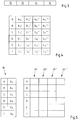
- the transmitter information received by the sensors AC is converted into reception situations as in Fig. 3 are represented as a data record.
- reception information 8 is shown as a data record.
- the received information 8 contains a transmitter identifier 10 of the transmitter 6, a sensor identifier 12 of one of the sensors AM and information about the received field strength 14 of the signal with which the transmitter identifier was received, as well as further test data or the like 16.
- the transmitter identifier 10 can be a unique character string which uniquely identifies each transmitter 6.
- the sensor identifier 12 can be a unique character string that uniquely identifies each sensor AM.
- the received field strength 14 can be information about how large the electrical field of the signal with which the transmitter identification was received in the sensor AC. This can be an amount, for example.
- These three data 10, 12, 14 together with test data 16, for example CRC test data, can each be transmitted from the sensors AM to the evaluation device 4.
- each sensor AM that receives the transmitter identifier 10 creates reception information 8 as shown in FIG Fig. 3 is shown.
- the information 12 on the sensor A-M and the reception field strength 14 are extracted for each individual transmitter 6 using the transmitter identifier 10.
- the information 12 from at least two sensors A-M with regard to the reception field strength can be understood as a current signature.
- At least one current signature preferably several current signatures, are assigned to a spatial area 2a-f, so that a matrix can be formed from position signatures, as shown in FIG Fig. 4 is shown.
- Fig. 4 shows for example a position signature which is assigned to the spatial area 2b. It can be seen that sensors A, B, C, D, E and I each store a set of reception field strengths A14 ', B14', C14 ', D14', E14 'and I14'. This information is assigned to the spatial area 2b. That is, the matrix as in Fig. 4 is shown, which is composed of various current signatures, is assigned to the spatial area 2b, so that the signatures become positional signatures.
- At least one position signature is preferably provided for each spatial area 2a-f, which follows at least one column of the matrix Fig. 4 corresponds, recorded, but preferably several position signatures in a matrix according to Fig. 4 .
- the position detection is then carried out in such a way that a current signature 18, as in FIG Fig. 5 indicated, is recorded, in which the information 12 on the respective sensors AI and the corresponding information 14 (A14 to I14) on the received field strengths are contained.
- the current signature with the individual position signatures 20 ', 20 ", 20"', 20 “” is then according to the matrix Fig. 4 compared, the value of the received field strength being compared in each case for each individual sensor and a sum of the difference amounts being determined.
- a sum of the difference between the respective stored reception field strengths and the reception field strengths of the current signature 18 is calculated.
- An average for the sum of the difference amounts across all position signatures 20'-20 “" can then be calculated. This is carried out for all matrices, ie for each of the rooms 2a-f there is a matrix according to Fig. 4 and the comparison according to Fig. 5 is carried out for every room.
- Fig. 6 shows an application example of position detection.
- a transmitter 6 can be present successively in different spatial areas 2a, b, c.
- This transmitter 6 can be, for example, a mobile handheld transmitter 6a or a separate component from this mobile handheld transmitter.
- Control elements are on the hand transmitter 6a 20a, 20b provided. With the control elements 20a, 20b it is possible, for example, to control certain functions of the home automation system.
- the control element 20a can be programmed in such a way that ceiling lighting of a spatial area 2a-c, if present, is always activated.
- the mobile transmitter 6a is now moved in the spatial areas 2a-f and it is first recognized, for example, that the mobile transmitter 6a is in the spatial area 2a. If the control element 20a is pressed at this moment, the ceiling lamp 22a, for example, is switched on or off depending on the position detected in the spatial area 2a.
- control element 20a is assigned a generic function, which, however, is assigned to a specific action or specific actuator depending on the recognized spatial area.
- Fig. 7 shows the time course of the transmission of a transmitter identifier 10 at intervals 24 by the transmitter 6.
- the interval duration of the intervals 24 can be detected by the evaluation device 4 and, according to the interval duration, the sensors AM can be activated so that they listen at certain times, whereby these times coincide with the transmission times of the transmitter identifier 10.
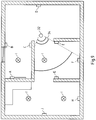
- Fig. 8 shows the floor plan 30 of the area 2.
- the area 2 is divided into the partial areas 2a-f. Walls 30a and fixed internals 30b can be seen in the floor plan 30.
- a transmitter 6 can be continuously monitored while it is moving in the floor plan 30.
- a transmitter 6 can e.g. on a house robot, e.g. a vacuum cleaner robot. From the position signatures received by the transmitter 6, it is determined where 30 walls 30a and internals 30b are located in the floor plan. No position signature is received in these areas so that these areas can be viewed as "dead" areas of the floor plan.
- the floor plan 30 can be used to position actuators and sensors therein. This is in the Figure 9 to recognize.
- the positioning of the sensors or actuators AJ can be done manually by placing the sensors or actuators AJ there in the current view of the floor plan 30. It is also possible to record the position signatures of the respective sensors or actuators AJ and to determine their absolute or relative position to one another in the floor plan 30.
- the sensors or actuators AJ are exemplary as follows.
- Sensor A is a thermostat that is connected to a radiator and thus also an actuator with an actuator for the radiators.
- Sensor B is, for example, a window opening sensor.
- Sensor C is a button.
- Sensor D is a motion detector.
- the sensors E and G are switches.
- sensors F, H and J are thermostats.
- the lamps I are representative of switch actuators.
- the user moves through the floor plan 30, which is represented by the user 32, for example, his position can be determined.
- the user 32 also frequently has an advertisement with him, which he determines in one, referred to here as 34 Can align the line of sight.
- the viewing direction 34 has been determined, the area of the floor plan 30 that can be seen in this viewing direction can be displayed.
- an augmented reality application can be supported.
- the user's display device captures an image in the viewing direction 34. This image is initially displayed on the display.
- FIG Fig. 10 Such a representation of an image in a certain viewing direction 34 is shown in FIG Fig. 10 shown.
- the display shows the captured image.
- part of the floor plan 30 can be shown in the display. So it is e.g. possible to show the walls 30a in the representation of the recording, e.g. as an overlay on the real image.
- sensors or actuators AJ are in the area of the field of vision.
- the example shown here is the sensors / actuators E, F, G, I, J.
- These sensors / actuators E, F, G, I, J are shown in the display by, for example, pictograms. It is also possible to display the status parameter or other information such as the name of the sensor / actuator E, F, G, I, J.
- a connection between the sensors / actuators E, F, G, I, J can then be shown to the user.
- the user can set this, for example, via a menu.
- the arrangement of the sensors / actuators E, F, G, I, J in Fig. 10 does not correspond to that in Fig. 9 , which is irrelevant for the understanding.
- the sensors / actuators A, B, C and I are still shown in the image that is shown.
- the user can have the assignment of the sensors to the actuators displayed.
- buttons C and the actuator I can also be seen.
- the rule can be programmed that when button C is pressed, actuator I remains switched on for 10 minutes.
- Fig. 10 is, for example, the display of congestion of the sensors / actuators E, F, G, I, J. But the user can also activate such a display via a menu.
- User gestures can also be recorded with the help of the camera that is present on the display device.
- the user could make a hand movement from the sensor C to the thermostat A. This hand movement could be captured by the camera.
- an assignment between a sensor and an actuator, for example, the button C and the thermostat A could first be stored. The user could then be shown a menu in which the program rules that are possible for such an assignment are displayed. In the present case, this could be, for example, an increase in the target temperature by X degrees Celsius for Y minutes.
- the user can then assign actions to the motion vectors 40, 42s, 42b.
- the action "Activate actuators I" can be assigned to motion vector 40.
- Similar things can be programmed for the vectors 42a, 42b.
- the vector 42a e.g. can be programmed to increase the target temperature of thermostat A by 1 degree Celsius, and for vector 42b to decrease the target temperature by 1 degree Celsius.
- the room temperature can be increased when entering the room, which is detected by the movement of the transmitter 6 along the vector 42a, and correspondingly reduced when leaving the room, by moving along the vector 42b.
- a movement corridor 44 is shown. Such a corridor 44 can also be programmed by the user in the floor plan 30.
- a trigger point 46 is drawn in as a surface, as the user can draw / define it in the floor plan 30.
- the action to increase the target temperature of the thermostat A in 1 degree Celsius can be assigned to this trigger point 44.
- another action can be assigned to trigger point 44. This can be, for example, the action "switch off the actuators I".
Landscapes
- Engineering & Computer Science (AREA)
- Automation & Control Theory (AREA)
- Physics & Mathematics (AREA)
- General Physics & Mathematics (AREA)
- Computer Networks & Wireless Communication (AREA)
- Signal Processing (AREA)
- General Engineering & Computer Science (AREA)
- Computer Vision & Pattern Recognition (AREA)
- Theoretical Computer Science (AREA)
- Human Computer Interaction (AREA)
- Selective Calling Equipment (AREA)
- Telephone Function (AREA)
Claims (11)
- Système domotique comprenant :- au moins un dispositif d'exploitation, des moyens de visualisation conçus pour l'affichage d'une vue au moins d'une partie d'un plan d'ensemble d'un environnement spatial du système domotique, et- des moyens de programmation conçus pour la programmation au moins d'une action d'un actionneur du système domotique, en se basant sur la vue du plan d'ensemble, qui est effectivement affichée, et en se basant sur une fonction de l'actionneur et/ou d'un capteur du système domotique,
caractérisé- en ce que le dispositif d'exploitation, à partir de signaux de réception d'un émetteur, lesdits signaux étant reçus par au moins deux capteurs, détecte, comme informations de réception, une intensité de champ de réception respective, ainsi qu'un identifiant d'émetteur et un identifiant de capteur, et ledit dispositif d'exploitation détermine une position d'après les informations de réception,- de sorte qu'un dispositif de visualisation mobile des moyens de visualisation représente une partie du plan d'ensemble, en fonction de la position détectée dans le plan d'ensemble. - Système domotique selon la revendication 1, caractérisé- en ce que les moyens de programmation sont conçus dans le but, en se basant sur la vue qui est effectivement affichée, d'affecter à un actionneur et/ou à un capteur une position se trouvant dans le plan d'ensemble.
- Système domotique selon la revendication 1 ou 2, caractérisé- en ce que les moyens de programmation sont conçus dans le but de définir, dans la vue qui est effectivement affichée, des vecteurs de mouvement virtuels et/ou des points de déclenchement virtuels se trouvant dans le plan d'ensemble, et d'affecter à chaque fois à ces vecteurs de mouvement et à ces points de déclenchement, au moins une action d'un actionneur.
- Système domotique selon l'une quelconque des revendications précédentes,
caractérisé- en ce que des moyens de détection sont conçus pour la détection du plan d'ensemble, en particulier en ce que les moyens de détection sont conçus pour la détection d'un plan d'ensemble en 3D. - Système domotique selon l'une quelconque des revendications précédentes,
caractérisé- en ce que les moyens de visualisation sont conçus pour l'affichage d'une vue du plan d'ensemble, ledit affichage étant réalisé en même temps qu'un affichage d'une image réelle. - Système domotique selon l'une quelconque des revendications précédentes,
caractérisé- en ce que les moyens de visualisation sont conçus pour l'affichage d'icônes représentant des actionneurs et/ou des capteurs, lesdites icônes étant affichées en même temps qu'une image réelle. - Système domotique selon l'une quelconque des revendications précédentes,
caractérisé- en ce que les moyens de visualisation sont conçus pour l'affichage des icônes en fonction d'un état d'un actionneur et/ou d'un capteur. - Système domotique selon l'une quelconque des revendications précédentes,
caractérisé- en ce que les moyens de programmation sont conçus pour la réception de valeurs d'état de variables d'environnement simulées, où les variables d'environnement ont une influence programmée sur un état d'un actionneur et/ou d'un capteur, et en ce que les moyens de visualisation sont conçus pour l'affichage d'un état de l'actionneur et/ou du capteur, l'état étant considéré en se basant sur les variables d'environnement simulées. - Système domotique selon l'une quelconque des revendications précédentes,
caractérisé- en ce que des moyens de détection sont conçus pour la détection d'un geste d'un utilisateur, en ce que les moyens de programmation exploitent le geste de l'utilisateur, qui a été détecté, en fonction de l'affichage du plan d'ensemble, et programment au moins un actionneur et/ou un capteur en fonction du geste de l'utilisateur et en fonction de la vue du plan d'ensemble, qui est effectivement affichée. - Système domotique selon l'une quelconque des revendications précédentes,
caractérisé- en ce que le dispositif d'exploitation détecte à chaque fois pour un émetteur, comme signature active, les intensités de champ de réception respectives et les identifiants de capteurs respectifs, qui sont détectés à partir des informations de réception provenant au moins de deux capteurs. - Procédé permettant de faire fonctionner un système domotique, en particulier selon l'une quelconque des revendications précédentes, procédé dans lequel- est affichée une vue au moins d'une partie d'un plan d'ensemble d'un environnement spatial du système domotique, et- au moins une action d'un actionneur du système domotique est programmée, en se basant sur la vue du plan d'ensemble, qui est effectivement affichée, et en se basant sur une fonction de l'actionneur et/ou d'un capteur du système domotique, caractérisé- en ce qu'une intensité de champ de réception respective est détectée en même temps qu'un identifiant d'émetteur et qu'un identifiant de capteur, ces informations considérées comme des informations de réception étant détectées à partir de signaux de réception d'un émetteur, lesdits signaux étant reçus par au moins deux capteurs, et une position est déterminée d'après les informations de réception,- de sorte qu'une partie du plan d'ensemble est représentée en fonction de la position détectée dans le plan d'ensemble.
Applications Claiming Priority (2)
| Application Number | Priority Date | Filing Date | Title |
|---|---|---|---|
| DE102016102402.3A DE102016102402A1 (de) | 2016-02-11 | 2016-02-11 | Heimautomatisierungssystem |
| PCT/EP2016/075761 WO2017137104A1 (fr) | 2016-02-11 | 2016-10-26 | Système domotique |
Publications (2)
| Publication Number | Publication Date |
|---|---|
| EP3414633A1 EP3414633A1 (fr) | 2018-12-19 |
| EP3414633B1 true EP3414633B1 (fr) | 2020-04-08 |
Family
ID=57209456
Family Applications (1)
| Application Number | Title | Priority Date | Filing Date |
|---|---|---|---|
| EP16788078.0A Active EP3414633B1 (fr) | 2016-02-11 | 2016-10-26 | Système domotique |
Country Status (7)
| Country | Link |
|---|---|
| US (1) | US20180351758A1 (fr) |
| EP (1) | EP3414633B1 (fr) |
| CN (1) | CN108604086A (fr) |
| CA (1) | CA3013523C (fr) |
| DE (1) | DE102016102402A1 (fr) |
| ES (1) | ES2795409T3 (fr) |
| WO (1) | WO2017137104A1 (fr) |
Families Citing this family (12)
| Publication number | Priority date | Publication date | Assignee | Title |
|---|---|---|---|---|
| MX350468B (es) | 2012-08-28 | 2017-09-07 | Delos Living Llc | Sistemas, metodos y articulos para mejorar el bienestar asociado con ambientes habitables. |
| EP3111411A4 (fr) | 2014-02-28 | 2017-08-09 | Delos Living, LLC | Systèmes, procédés et articles pour améliorer le bien-être associé à des environnements habitables |
| CN107251031A (zh) | 2015-01-13 | 2017-10-13 | 戴尔斯生活有限责任公司 | 用于监测和增强人体健康的系统、方法和制品 |
| WO2018039433A1 (fr) | 2016-08-24 | 2018-03-01 | Delos Living Llc | Systèmes, procédés et articles permettant d'accroître le bien-être associé à des environnements habitables |
| WO2019046580A1 (fr) | 2017-08-30 | 2019-03-07 | Delos Living Llc | Systèmes, procédés et articles pour évaluer et/ou améliorer la santé et le bien-être |
| WO2019043500A1 (fr) * | 2017-08-30 | 2019-03-07 | Belimo Holding Sa | Attribution automatique entre des dispositifs de commande de flux, des dispositifs de capteur et des dispositifs de commande dans une application hvac |
| WO2020055872A1 (fr) | 2018-09-14 | 2020-03-19 | Delos Living Llc | Systèmes et procédés d'assainissement d'air |
| DE102019101192A1 (de) * | 2019-01-17 | 2020-07-23 | Innogy Se | Kamerasystem und Heimautomatisierungssystem mit einem Kamerasystem |
| WO2020176503A1 (fr) | 2019-02-26 | 2020-09-03 | Delos Living Llc | Procédé et appareil d'éclairage dans un environnement de bureau |
| WO2020198183A1 (fr) | 2019-03-25 | 2020-10-01 | Delos Living Llc | Systèmes et procédés de surveillance acoustique |
| CN111123715A (zh) * | 2019-05-25 | 2020-05-08 | 深圳市艾佩特科技有限公司 | 一种智能家居安防监控方法 |
| CN112866070A (zh) * | 2021-01-21 | 2021-05-28 | 珠海格力电器股份有限公司 | 一种交互方法、装置、存储介质及电子设备 |
Family Cites Families (32)
| Publication number | Priority date | Publication date | Assignee | Title |
|---|---|---|---|---|
| CA2203591A1 (fr) * | 1997-04-24 | 1998-10-24 | John Peterson | Controleur pour systemes domestiques et systemes de securite |
| US7019644B2 (en) * | 2003-02-04 | 2006-03-28 | Barrie Robert P | Mobile object monitoring system |
| US8323106B2 (en) * | 2008-05-30 | 2012-12-04 | Sony Computer Entertainment America Llc | Determination of controller three-dimensional location using image analysis and ultrasonic communication |
| GB0324098D0 (en) * | 2003-10-15 | 2003-11-19 | Koninkl Philips Electronics Nv | Method and apparatus for indicating the location of an object |
| US8965460B1 (en) * | 2004-01-30 | 2015-02-24 | Ip Holdings, Inc. | Image and augmented reality based networks using mobile devices and intelligent electronic glasses |
| WO2006082498A1 (fr) * | 2005-02-01 | 2006-08-10 | Awox Sa | Procede et dispositif d'echange de donnees |
| US7567844B2 (en) * | 2006-03-17 | 2009-07-28 | Honeywell International Inc. | Building management system |
| US20080310707A1 (en) * | 2007-06-15 | 2008-12-18 | Microsoft Corporation | Virtual reality enhancement using real world data |
| WO2010028135A2 (fr) * | 2008-09-03 | 2010-03-11 | Siemens Industry, Inc. | Système et procédé de gestion d'immeuble sans fil passive et active |
| US20110071685A1 (en) * | 2009-09-03 | 2011-03-24 | Johnson Controls Technology Company | Creation and use of software defined building objects in building management systems and applications |
| US8830267B2 (en) * | 2009-11-16 | 2014-09-09 | Alliance For Sustainable Energy, Llc | Augmented reality building operations tool |
| US8668498B2 (en) * | 2011-03-08 | 2014-03-11 | Bank Of America Corporation | Real-time video image analysis for providing virtual interior design |
| DE102011102038A1 (de) * | 2011-05-19 | 2012-11-22 | Rwe Effizienz Gmbh | Heimautomatisierungssteuerungssystem sowie Verfahren zum Steuern einer Einrichtung eines Heimautomatisierungssteuerungssystems |
| WO2013030361A1 (fr) * | 2011-09-02 | 2013-03-07 | Msr-Solutions Gmbh | Système domotique et dispositif commutateur destiné à des équipements domotiques et doté d'une unité clavier |
| KR20130110907A (ko) * | 2012-03-30 | 2013-10-10 | 삼성전자주식회사 | 가상 현실과 증강 현실을 이용한 원격 제어 장치 및 방법 |
| US9233472B2 (en) * | 2013-01-18 | 2016-01-12 | Irobot Corporation | Mobile robot providing environmental mapping for household environmental control |
| US9375847B2 (en) * | 2013-01-18 | 2016-06-28 | Irobot Corporation | Environmental management systems including mobile robots and methods using same |
| KR102105463B1 (ko) * | 2013-09-02 | 2020-04-28 | 엘지전자 주식회사 | 이동 단말기 및 그것의 제어 방법 |
| US9704295B2 (en) * | 2013-11-05 | 2017-07-11 | Microsoft Technology Licensing, Llc | Construction of synthetic augmented reality environment |
| WO2015069652A1 (fr) * | 2013-11-07 | 2015-05-14 | a la mode technologies, inc. | Collecte d'informations relatives à un sujet à proximité d'un utilisateur |
| US9558592B2 (en) * | 2013-12-31 | 2017-01-31 | Daqri, Llc | Visualization of physical interactions in augmented reality |
| US9921557B2 (en) * | 2014-01-15 | 2018-03-20 | SILVAIR Sp. z o.o. | Automation system comprising a monitoring device and methods therefor |
| US20150198941A1 (en) * | 2014-01-15 | 2015-07-16 | John C. Pederson | Cyber Life Electronic Networking and Commerce Operating Exchange |
| US9571986B2 (en) * | 2014-05-07 | 2017-02-14 | Johnson Controls Technology Company | Systems and methods for detecting and using equipment location in a building management system |
| US10782657B2 (en) * | 2014-05-27 | 2020-09-22 | Ultrahaptics IP Two Limited | Systems and methods of gestural interaction in a pervasive computing environment |
| WO2015183014A1 (fr) * | 2014-05-28 | 2015-12-03 | Samsung Electronics Co., Ltd. | Appareil et procédé de commande de dispositifs de l'internet des objets |
| US9639098B2 (en) * | 2014-06-17 | 2017-05-02 | Magnum Energy Solutions, LLC | Thermostat and messaging device and methods thereof |
| US9810538B2 (en) * | 2014-08-22 | 2017-11-07 | Verizon Patent And Licensing Inc. | Apparatus, method, and system for providing beacon-based navigation |
| US9196432B1 (en) * | 2014-09-24 | 2015-11-24 | James Thomas O'Keeffe | Smart electrical switch with audio capability |
| US10320924B2 (en) * | 2014-10-08 | 2019-06-11 | Disney Enterprises, Inc. | Location-based mobile storytelling using beacons |
| US9565521B1 (en) * | 2015-08-14 | 2017-02-07 | Samsung Electronics Co., Ltd. | Automatic semantic labeling based on activity recognition |
| US10091017B2 (en) * | 2015-12-30 | 2018-10-02 | Echostar Technologies International Corporation | Personalized home automation control based on individualized profiling |
-
2016
- 2016-02-11 DE DE102016102402.3A patent/DE102016102402A1/de not_active Withdrawn
- 2016-10-26 WO PCT/EP2016/075761 patent/WO2017137104A1/fr active Application Filing
- 2016-10-26 ES ES16788078T patent/ES2795409T3/es active Active
- 2016-10-26 CA CA3013523A patent/CA3013523C/fr not_active Expired - Fee Related
- 2016-10-26 CN CN201680081611.0A patent/CN108604086A/zh active Pending
- 2016-10-26 EP EP16788078.0A patent/EP3414633B1/fr active Active
-
2018
- 2018-08-09 US US16/059,291 patent/US20180351758A1/en not_active Abandoned
Non-Patent Citations (1)
| Title |
|---|
| None * |
Also Published As
| Publication number | Publication date |
|---|---|
| CN108604086A (zh) | 2018-09-28 |
| ES2795409T3 (es) | 2020-11-23 |
| CA3013523C (fr) | 2019-07-09 |
| DE102016102402A1 (de) | 2017-08-17 |
| WO2017137104A1 (fr) | 2017-08-17 |
| EP3414633A1 (fr) | 2018-12-19 |
| US20180351758A1 (en) | 2018-12-06 |
| CA3013523A1 (fr) | 2017-08-17 |
Similar Documents
| Publication | Publication Date | Title |
|---|---|---|
| EP3414633B1 (fr) | Système domotique | |
| EP1956455B1 (fr) | Méthode pour intégrer des noeuds de réseau | |
| EP1987370B1 (fr) | Disposition de capteur/activateur et procede pour la localisation respectivement le guidage d'objets et/ou de personnes mobiles sur une surface a l'aide d'une disposition de capteur/activateur | |
| DE60317546T2 (de) | System und verfahren zur bereitstellung standortbasierter information | |
| EP3593335B1 (fr) | Procédé pour faire fonctionner un système et système correspondant | |
| DE112018001883T5 (de) | Belegungsabschätzung mittels nichtparametrischen Online-Änderungspunkt-Erfassungsalgorithmus und Vorrichtungen, Systeme, und Software für Selbiges | |
| DE102016113060A1 (de) | Verfahren zum Steuern eines Objekts | |
| EP3274735A1 (fr) | Système et procédé de poursuite du porteur d'une unité de communication mobile | |
| DE102014007177A1 (de) | System zum Steuern wenigstens eines Hausgerätes | |
| EP3479658B1 (fr) | Système d'éclairage avec acquisition de valeurs mesurées basée sur la localisation | |
| EP2890056A1 (fr) | Assistance aux utilisateurs dans un environnement domestique intelligent | |
| EP3357199B1 (fr) | Système de domotique | |
| DE102016222471A1 (de) | System und Verfahren zur Erstellung von Anwesenheitsprofilen für die Gebäudesteuerung | |
| EP2907366B1 (fr) | Système de commande conçu pour des récepteurs disposés de façon répartie, notamment pour des appareils destinés à faire fonctionner des lampes et procédé de mise en ouvre du système | |
| DE102013103851B4 (de) | Verfahren zum Ansteuern von gebäudesystemtechnischen Aktoren | |
| DE102008057751B4 (de) | Vorrichtung und Verfahren zum Lastmanagement | |
| EP3528226B1 (fr) | Appareil de système destiné à fonctionner dans un réseau sans fil | |
| DE102016110456A1 (de) | Verfahren und Vorrichtung zur Kommissionierung eines Gebäudeautomationssystem | |
| DE102014117117B3 (de) | Verfahren zum Ansteuern wenigstens eines Aktors mit einem tragbaren Bedienteil | |
| DE102014019534A1 (de) | Vorrichtung zur verwendung in einem dynamischen netzwerk und dynamisches netzwerk | |
| WO2013120527A1 (fr) | Ensemble réseau radio pour un édifice | |
| WO2017194230A1 (fr) | Appareil de communication mobile pourvu d'une présentation interface utilisateur dépendante d'un paramètre détecté sur une interface | |
| EP4094016A1 (fr) | Dispositif de commande pour actionner un capteur de mouvement | |
| DE102016120816B4 (de) | Elektrisches/elektronisches Steuergerät | |
| EP3825792A1 (fr) | Procédé de commande d'au moins un actionneur d'un système domotique et/ou de génération et/ou de transmission d'au moins un message de commande à au moins un actionneur du système domotique à l'aide d'un dispositif d'actionnement, système, utilisation d'un dispositif d'actionnement, d'un agencement de capteur ou d'un agencement de commande, programme informatique et support lisible par ordinateur |
Legal Events
| Date | Code | Title | Description |
|---|---|---|---|
| STAA | Information on the status of an ep patent application or granted ep patent |
Free format text: STATUS: UNKNOWN |
|
| STAA | Information on the status of an ep patent application or granted ep patent |
Free format text: STATUS: THE INTERNATIONAL PUBLICATION HAS BEEN MADE |
|
| PUAI | Public reference made under article 153(3) epc to a published international application that has entered the european phase |
Free format text: ORIGINAL CODE: 0009012 |
|
| STAA | Information on the status of an ep patent application or granted ep patent |
Free format text: STATUS: REQUEST FOR EXAMINATION WAS MADE |
|
| 17P | Request for examination filed |
Effective date: 20180515 |
|
| AK | Designated contracting states |
Kind code of ref document: A1 Designated state(s): AL AT BE BG CH CY CZ DE DK EE ES FI FR GB GR HR HU IE IS IT LI LT LU LV MC MK MT NL NO PL PT RO RS SE SI SK SM TR |
|
| AX | Request for extension of the european patent |
Extension state: BA ME |
|
| DAV | Request for validation of the european patent (deleted) | ||
| DAX | Request for extension of the european patent (deleted) | ||
| RIC1 | Information provided on ipc code assigned before grant |
Ipc: H04L 12/28 20060101ALI20190912BHEP Ipc: G05B 15/02 20060101AFI20190912BHEP |
|
| GRAP | Despatch of communication of intention to grant a patent |
Free format text: ORIGINAL CODE: EPIDOSNIGR1 |
|
| STAA | Information on the status of an ep patent application or granted ep patent |
Free format text: STATUS: GRANT OF PATENT IS INTENDED |
|
| INTG | Intention to grant announced |
Effective date: 20191021 |
|
| GRAS | Grant fee paid |
Free format text: ORIGINAL CODE: EPIDOSNIGR3 |
|
| GRAA | (expected) grant |
Free format text: ORIGINAL CODE: 0009210 |
|
| STAA | Information on the status of an ep patent application or granted ep patent |
Free format text: STATUS: THE PATENT HAS BEEN GRANTED |
|
| AK | Designated contracting states |
Kind code of ref document: B1 Designated state(s): AL AT BE BG CH CY CZ DE DK EE ES FI FR GB GR HR HU IE IS IT LI LT LU LV MC MK MT NL NO PL PT RO RS SE SI SK SM TR |
|
| REG | Reference to a national code |
Ref country code: CH Ref legal event code: EP Ref country code: AT Ref legal event code: REF Ref document number: 1255217 Country of ref document: AT Kind code of ref document: T Effective date: 20200415 |
|
| REG | Reference to a national code |
Ref country code: DE Ref legal event code: R096 Ref document number: 502016009497 Country of ref document: DE |
|
| REG | Reference to a national code |
Ref country code: IE Ref legal event code: FG4D Free format text: LANGUAGE OF EP DOCUMENT: GERMAN |
|
| REG | Reference to a national code |
Ref country code: NL Ref legal event code: FP |
|
| REG | Reference to a national code |
Ref country code: CH Ref legal event code: NV Representative=s name: DENNEMEYER AG, CH |
|
| REG | Reference to a national code |
Ref country code: SE Ref legal event code: TRGR |
|
| REG | Reference to a national code |
Ref country code: LT Ref legal event code: MG4D |
|
| PG25 | Lapsed in a contracting state [announced via postgrant information from national office to epo] |
Ref country code: NO Free format text: LAPSE BECAUSE OF FAILURE TO SUBMIT A TRANSLATION OF THE DESCRIPTION OR TO PAY THE FEE WITHIN THE PRESCRIBED TIME-LIMIT Effective date: 20200708 Ref country code: FI Free format text: LAPSE BECAUSE OF FAILURE TO SUBMIT A TRANSLATION OF THE DESCRIPTION OR TO PAY THE FEE WITHIN THE PRESCRIBED TIME-LIMIT Effective date: 20200408 Ref country code: GR Free format text: LAPSE BECAUSE OF FAILURE TO SUBMIT A TRANSLATION OF THE DESCRIPTION OR TO PAY THE FEE WITHIN THE PRESCRIBED TIME-LIMIT Effective date: 20200709 Ref country code: PT Free format text: LAPSE BECAUSE OF FAILURE TO SUBMIT A TRANSLATION OF THE DESCRIPTION OR TO PAY THE FEE WITHIN THE PRESCRIBED TIME-LIMIT Effective date: 20200817 Ref country code: LT Free format text: LAPSE BECAUSE OF FAILURE TO SUBMIT A TRANSLATION OF THE DESCRIPTION OR TO PAY THE FEE WITHIN THE PRESCRIBED TIME-LIMIT Effective date: 20200408 Ref country code: IS Free format text: LAPSE BECAUSE OF FAILURE TO SUBMIT A TRANSLATION OF THE DESCRIPTION OR TO PAY THE FEE WITHIN THE PRESCRIBED TIME-LIMIT Effective date: 20200808 |
|
| REG | Reference to a national code |
Ref country code: ES Ref legal event code: FG2A Ref document number: 2795409 Country of ref document: ES Kind code of ref document: T3 Effective date: 20201123 |
|
| PG25 | Lapsed in a contracting state [announced via postgrant information from national office to epo] |
Ref country code: HR Free format text: LAPSE BECAUSE OF FAILURE TO SUBMIT A TRANSLATION OF THE DESCRIPTION OR TO PAY THE FEE WITHIN THE PRESCRIBED TIME-LIMIT Effective date: 20200408 Ref country code: BG Free format text: LAPSE BECAUSE OF FAILURE TO SUBMIT A TRANSLATION OF THE DESCRIPTION OR TO PAY THE FEE WITHIN THE PRESCRIBED TIME-LIMIT Effective date: 20200708 Ref country code: LV Free format text: LAPSE BECAUSE OF FAILURE TO SUBMIT A TRANSLATION OF THE DESCRIPTION OR TO PAY THE FEE WITHIN THE PRESCRIBED TIME-LIMIT Effective date: 20200408 Ref country code: RS Free format text: LAPSE BECAUSE OF FAILURE TO SUBMIT A TRANSLATION OF THE DESCRIPTION OR TO PAY THE FEE WITHIN THE PRESCRIBED TIME-LIMIT Effective date: 20200408 |
|
| PG25 | Lapsed in a contracting state [announced via postgrant information from national office to epo] |
Ref country code: AL Free format text: LAPSE BECAUSE OF FAILURE TO SUBMIT A TRANSLATION OF THE DESCRIPTION OR TO PAY THE FEE WITHIN THE PRESCRIBED TIME-LIMIT Effective date: 20200408 |
|
| PGFP | Annual fee paid to national office [announced via postgrant information from national office to epo] |
Ref country code: LU Payment date: 20201020 Year of fee payment: 5 Ref country code: NL Payment date: 20201020 Year of fee payment: 5 |
|
| REG | Reference to a national code |
Ref country code: DE Ref legal event code: R097 Ref document number: 502016009497 Country of ref document: DE |
|
| PG25 | Lapsed in a contracting state [announced via postgrant information from national office to epo] |
Ref country code: CZ Free format text: LAPSE BECAUSE OF FAILURE TO SUBMIT A TRANSLATION OF THE DESCRIPTION OR TO PAY THE FEE WITHIN THE PRESCRIBED TIME-LIMIT Effective date: 20200408 Ref country code: SM Free format text: LAPSE BECAUSE OF FAILURE TO SUBMIT A TRANSLATION OF THE DESCRIPTION OR TO PAY THE FEE WITHIN THE PRESCRIBED TIME-LIMIT Effective date: 20200408 Ref country code: RO Free format text: LAPSE BECAUSE OF FAILURE TO SUBMIT A TRANSLATION OF THE DESCRIPTION OR TO PAY THE FEE WITHIN THE PRESCRIBED TIME-LIMIT Effective date: 20200408 Ref country code: EE Free format text: LAPSE BECAUSE OF FAILURE TO SUBMIT A TRANSLATION OF THE DESCRIPTION OR TO PAY THE FEE WITHIN THE PRESCRIBED TIME-LIMIT Effective date: 20200408 Ref country code: DK Free format text: LAPSE BECAUSE OF FAILURE TO SUBMIT A TRANSLATION OF THE DESCRIPTION OR TO PAY THE FEE WITHIN THE PRESCRIBED TIME-LIMIT Effective date: 20200408 |
|
| PGFP | Annual fee paid to national office [announced via postgrant information from national office to epo] |
Ref country code: DE Payment date: 20201022 Year of fee payment: 5 Ref country code: ES Payment date: 20201117 Year of fee payment: 5 Ref country code: GB Payment date: 20201022 Year of fee payment: 5 Ref country code: CH Payment date: 20201022 Year of fee payment: 5 Ref country code: SE Payment date: 20201022 Year of fee payment: 5 Ref country code: FR Payment date: 20201020 Year of fee payment: 5 Ref country code: IT Payment date: 20201030 Year of fee payment: 5 |
|
| PLBE | No opposition filed within time limit |
Free format text: ORIGINAL CODE: 0009261 |
|
| STAA | Information on the status of an ep patent application or granted ep patent |
Free format text: STATUS: NO OPPOSITION FILED WITHIN TIME LIMIT |
|
| PG25 | Lapsed in a contracting state [announced via postgrant information from national office to epo] |
Ref country code: SK Free format text: LAPSE BECAUSE OF FAILURE TO SUBMIT A TRANSLATION OF THE DESCRIPTION OR TO PAY THE FEE WITHIN THE PRESCRIBED TIME-LIMIT Effective date: 20200408 Ref country code: PL Free format text: LAPSE BECAUSE OF FAILURE TO SUBMIT A TRANSLATION OF THE DESCRIPTION OR TO PAY THE FEE WITHIN THE PRESCRIBED TIME-LIMIT Effective date: 20200408 |
|
| PGFP | Annual fee paid to national office [announced via postgrant information from national office to epo] |
Ref country code: BE Payment date: 20201020 Year of fee payment: 5 |
|
| 26N | No opposition filed |
Effective date: 20210112 |
|
| PG25 | Lapsed in a contracting state [announced via postgrant information from national office to epo] |
Ref country code: SI Free format text: LAPSE BECAUSE OF FAILURE TO SUBMIT A TRANSLATION OF THE DESCRIPTION OR TO PAY THE FEE WITHIN THE PRESCRIBED TIME-LIMIT Effective date: 20200408 |
|
| PG25 | Lapsed in a contracting state [announced via postgrant information from national office to epo] |
Ref country code: MC Free format text: LAPSE BECAUSE OF FAILURE TO SUBMIT A TRANSLATION OF THE DESCRIPTION OR TO PAY THE FEE WITHIN THE PRESCRIBED TIME-LIMIT Effective date: 20200408 |
|
| PG25 | Lapsed in a contracting state [announced via postgrant information from national office to epo] |
Ref country code: IE Free format text: LAPSE BECAUSE OF NON-PAYMENT OF DUE FEES Effective date: 20201026 |
|
| REG | Reference to a national code |
Ref country code: DE Ref legal event code: R119 Ref document number: 502016009497 Country of ref document: DE |
|
| REG | Reference to a national code |
Ref country code: CH Ref legal event code: PL Ref country code: SE Ref legal event code: EUG |
|
| PG25 | Lapsed in a contracting state [announced via postgrant information from national office to epo] |
Ref country code: TR Free format text: LAPSE BECAUSE OF FAILURE TO SUBMIT A TRANSLATION OF THE DESCRIPTION OR TO PAY THE FEE WITHIN THE PRESCRIBED TIME-LIMIT Effective date: 20200408 Ref country code: MT Free format text: LAPSE BECAUSE OF FAILURE TO SUBMIT A TRANSLATION OF THE DESCRIPTION OR TO PAY THE FEE WITHIN THE PRESCRIBED TIME-LIMIT Effective date: 20200408 Ref country code: CY Free format text: LAPSE BECAUSE OF FAILURE TO SUBMIT A TRANSLATION OF THE DESCRIPTION OR TO PAY THE FEE WITHIN THE PRESCRIBED TIME-LIMIT Effective date: 20200408 |
|
| REG | Reference to a national code |
Ref country code: NL Ref legal event code: MM Effective date: 20211101 |
|
| REG | Reference to a national code |
Ref country code: BE Ref legal event code: MM Effective date: 20211031 |
|
| GBPC | Gb: european patent ceased through non-payment of renewal fee |
Effective date: 20211026 |
|
| PG25 | Lapsed in a contracting state [announced via postgrant information from national office to epo] |
Ref country code: MK Free format text: LAPSE BECAUSE OF FAILURE TO SUBMIT A TRANSLATION OF THE DESCRIPTION OR TO PAY THE FEE WITHIN THE PRESCRIBED TIME-LIMIT Effective date: 20200408 |
|
| PG25 | Lapsed in a contracting state [announced via postgrant information from national office to epo] |
Ref country code: SE Free format text: LAPSE BECAUSE OF NON-PAYMENT OF DUE FEES Effective date: 20211027 Ref country code: NL Free format text: LAPSE BECAUSE OF NON-PAYMENT OF DUE FEES Effective date: 20211101 Ref country code: LU Free format text: LAPSE BECAUSE OF NON-PAYMENT OF DUE FEES Effective date: 20211026 Ref country code: GB Free format text: LAPSE BECAUSE OF NON-PAYMENT OF DUE FEES Effective date: 20211026 Ref country code: DE Free format text: LAPSE BECAUSE OF NON-PAYMENT OF DUE FEES Effective date: 20220503 Ref country code: BE Free format text: LAPSE BECAUSE OF NON-PAYMENT OF DUE FEES Effective date: 20211031 |
|
| PG25 | Lapsed in a contracting state [announced via postgrant information from national office to epo] |
Ref country code: LI Free format text: LAPSE BECAUSE OF NON-PAYMENT OF DUE FEES Effective date: 20211031 Ref country code: CH Free format text: LAPSE BECAUSE OF NON-PAYMENT OF DUE FEES Effective date: 20211031 |
|
| PG25 | Lapsed in a contracting state [announced via postgrant information from national office to epo] |
Ref country code: FR Free format text: LAPSE BECAUSE OF NON-PAYMENT OF DUE FEES Effective date: 20211031 |
|
| PG25 | Lapsed in a contracting state [announced via postgrant information from national office to epo] |
Ref country code: IT Free format text: LAPSE BECAUSE OF NON-PAYMENT OF DUE FEES Effective date: 20211026 |
|
| REG | Reference to a national code |
Ref country code: AT Ref legal event code: MM01 Ref document number: 1255217 Country of ref document: AT Kind code of ref document: T Effective date: 20211026 |
|
| PG25 | Lapsed in a contracting state [announced via postgrant information from national office to epo] |
Ref country code: AT Free format text: LAPSE BECAUSE OF NON-PAYMENT OF DUE FEES Effective date: 20211026 |
|
| REG | Reference to a national code |
Ref country code: ES Ref legal event code: FD2A Effective date: 20230206 |
|
| PG25 | Lapsed in a contracting state [announced via postgrant information from national office to epo] |
Ref country code: ES Free format text: LAPSE BECAUSE OF NON-PAYMENT OF DUE FEES Effective date: 20211027 |