EP3413587A1 - Hörgerät, insbesondere hinter-dem-ohr-hörhilfegerät - Google Patents
Hörgerät, insbesondere hinter-dem-ohr-hörhilfegerät Download PDFInfo
- Publication number
- EP3413587A1 EP3413587A1 EP18170911.4A EP18170911A EP3413587A1 EP 3413587 A1 EP3413587 A1 EP 3413587A1 EP 18170911 A EP18170911 A EP 18170911A EP 3413587 A1 EP3413587 A1 EP 3413587A1
- Authority
- EP
- European Patent Office
- Prior art keywords
- hearing aid
- antenna element
- film
- shield
- film structure
- Prior art date
- Legal status (The legal status is an assumption and is not a legal conclusion. Google has not performed a legal analysis and makes no representation as to the accuracy of the status listed.)
- Granted
Links
- 238000004146 energy storage Methods 0.000 claims abstract description 47
- 230000005540 biological transmission Effects 0.000 claims abstract description 7
- 230000008054 signal transmission Effects 0.000 claims abstract description 4
- 238000004804 winding Methods 0.000 claims description 16
- 230000002093 peripheral effect Effects 0.000 claims description 13
- RYGMFSIKBFXOCR-UHFFFAOYSA-N Copper Chemical compound [Cu] RYGMFSIKBFXOCR-UHFFFAOYSA-N 0.000 claims description 11
- 229910052802 copper Inorganic materials 0.000 claims description 7
- 239000010949 copper Substances 0.000 claims description 7
- 239000002907 paramagnetic material Substances 0.000 claims description 6
- 230000005292 diamagnetic effect Effects 0.000 claims description 4
- 239000002889 diamagnetic material Substances 0.000 claims description 4
- 239000002902 ferrimagnetic material Substances 0.000 claims description 3
- 230000005294 ferromagnetic effect Effects 0.000 claims description 3
- 239000003302 ferromagnetic material Substances 0.000 claims description 3
- 230000005291 magnetic effect Effects 0.000 description 18
- 238000004891 communication Methods 0.000 description 11
- 230000005236 sound signal Effects 0.000 description 10
- 230000035945 sensitivity Effects 0.000 description 9
- 239000011888 foil Substances 0.000 description 8
- 238000012545 processing Methods 0.000 description 7
- 238000011161 development Methods 0.000 description 6
- 230000018109 developmental process Effects 0.000 description 6
- 210000000613 ear canal Anatomy 0.000 description 5
- 230000001939 inductive effect Effects 0.000 description 5
- 238000005452 bending Methods 0.000 description 4
- 239000004020 conductor Substances 0.000 description 4
- 239000011889 copper foil Substances 0.000 description 4
- 238000013461 design Methods 0.000 description 4
- 239000000463 material Substances 0.000 description 4
- 230000035699 permeability Effects 0.000 description 4
- 229910000859 α-Fe Inorganic materials 0.000 description 4
- 238000010438 heat treatment Methods 0.000 description 3
- 238000004519 manufacturing process Methods 0.000 description 3
- 230000015572 biosynthetic process Effects 0.000 description 2
- 238000000034 method Methods 0.000 description 2
- 230000035515 penetration Effects 0.000 description 2
- 230000008569 process Effects 0.000 description 2
- 238000012546 transfer Methods 0.000 description 2
- HBBGRARXTFLTSG-UHFFFAOYSA-N Lithium ion Chemical compound [Li+] HBBGRARXTFLTSG-UHFFFAOYSA-N 0.000 description 1
- XAGFODPZIPBFFR-UHFFFAOYSA-N aluminium Chemical compound [Al] XAGFODPZIPBFFR-UHFFFAOYSA-N 0.000 description 1
- 229910052782 aluminium Inorganic materials 0.000 description 1
- 230000008859 change Effects 0.000 description 1
- 238000010276 construction Methods 0.000 description 1
- 230000006735 deficit Effects 0.000 description 1
- 230000001419 dependent effect Effects 0.000 description 1
- 210000005069 ears Anatomy 0.000 description 1
- 238000005516 engineering process Methods 0.000 description 1
- 230000020169 heat generation Effects 0.000 description 1
- 230000010354 integration Effects 0.000 description 1
- 229910001416 lithium ion Inorganic materials 0.000 description 1
- BASFCYQUMIYNBI-UHFFFAOYSA-N platinum Chemical compound [Pt] BASFCYQUMIYNBI-UHFFFAOYSA-N 0.000 description 1
- 230000009467 reduction Effects 0.000 description 1
- 210000003625 skull Anatomy 0.000 description 1
- 238000005476 soldering Methods 0.000 description 1
- 230000007480 spreading Effects 0.000 description 1
- 238000003892 spreading Methods 0.000 description 1
Images


Classifications
-
- H—ELECTRICITY
- H04—ELECTRIC COMMUNICATION TECHNIQUE
- H04R—LOUDSPEAKERS, MICROPHONES, GRAMOPHONE PICK-UPS OR LIKE ACOUSTIC ELECTROMECHANICAL TRANSDUCERS; DEAF-AID SETS; PUBLIC ADDRESS SYSTEMS
- H04R25/00—Deaf-aid sets, i.e. electro-acoustic or electro-mechanical hearing aids; Electric tinnitus maskers providing an auditory perception
- H04R25/50—Customised settings for obtaining desired overall acoustical characteristics
-
- H—ELECTRICITY
- H01—ELECTRIC ELEMENTS
- H01Q—ANTENNAS, i.e. RADIO AERIALS
- H01Q1/00—Details of, or arrangements associated with, antennas
- H01Q1/27—Adaptation for use in or on movable bodies
- H01Q1/273—Adaptation for carrying or wearing by persons or animals
-
- H—ELECTRICITY
- H01—ELECTRIC ELEMENTS
- H01Q—ANTENNAS, i.e. RADIO AERIALS
- H01Q7/00—Loop antennas with a substantially uniform current distribution around the loop and having a directional radiation pattern in a plane perpendicular to the plane of the loop
- H01Q7/06—Loop antennas with a substantially uniform current distribution around the loop and having a directional radiation pattern in a plane perpendicular to the plane of the loop with core of ferromagnetic material
- H01Q7/08—Ferrite rod or like elongated core
-
- H—ELECTRICITY
- H02—GENERATION; CONVERSION OR DISTRIBUTION OF ELECTRIC POWER
- H02J—CIRCUIT ARRANGEMENTS OR SYSTEMS FOR SUPPLYING OR DISTRIBUTING ELECTRIC POWER; SYSTEMS FOR STORING ELECTRIC ENERGY
- H02J50/00—Circuit arrangements or systems for wireless supply or distribution of electric power
- H02J50/005—Mechanical details of housing or structure aiming to accommodate the power transfer means, e.g. mechanical integration of coils, antennas or transducers into emitting or receiving devices
-
- H—ELECTRICITY
- H02—GENERATION; CONVERSION OR DISTRIBUTION OF ELECTRIC POWER
- H02J—CIRCUIT ARRANGEMENTS OR SYSTEMS FOR SUPPLYING OR DISTRIBUTING ELECTRIC POWER; SYSTEMS FOR STORING ELECTRIC ENERGY
- H02J50/00—Circuit arrangements or systems for wireless supply or distribution of electric power
- H02J50/10—Circuit arrangements or systems for wireless supply or distribution of electric power using inductive coupling
-
- H—ELECTRICITY
- H04—ELECTRIC COMMUNICATION TECHNIQUE
- H04R—LOUDSPEAKERS, MICROPHONES, GRAMOPHONE PICK-UPS OR LIKE ACOUSTIC ELECTROMECHANICAL TRANSDUCERS; DEAF-AID SETS; PUBLIC ADDRESS SYSTEMS
- H04R25/00—Deaf-aid sets, i.e. electro-acoustic or electro-mechanical hearing aids; Electric tinnitus maskers providing an auditory perception
- H04R25/55—Deaf-aid sets, i.e. electro-acoustic or electro-mechanical hearing aids; Electric tinnitus maskers providing an auditory perception using an external connection, either wireless or wired
- H04R25/552—Binaural
-
- H—ELECTRICITY
- H04—ELECTRIC COMMUNICATION TECHNIQUE
- H04R—LOUDSPEAKERS, MICROPHONES, GRAMOPHONE PICK-UPS OR LIKE ACOUSTIC ELECTROMECHANICAL TRANSDUCERS; DEAF-AID SETS; PUBLIC ADDRESS SYSTEMS
- H04R25/00—Deaf-aid sets, i.e. electro-acoustic or electro-mechanical hearing aids; Electric tinnitus maskers providing an auditory perception
- H04R25/55—Deaf-aid sets, i.e. electro-acoustic or electro-mechanical hearing aids; Electric tinnitus maskers providing an auditory perception using an external connection, either wireless or wired
- H04R25/554—Deaf-aid sets, i.e. electro-acoustic or electro-mechanical hearing aids; Electric tinnitus maskers providing an auditory perception using an external connection, either wireless or wired using a wireless connection, e.g. between microphone and amplifier or using Tcoils
-
- H—ELECTRICITY
- H04—ELECTRIC COMMUNICATION TECHNIQUE
- H04R—LOUDSPEAKERS, MICROPHONES, GRAMOPHONE PICK-UPS OR LIKE ACOUSTIC ELECTROMECHANICAL TRANSDUCERS; DEAF-AID SETS; PUBLIC ADDRESS SYSTEMS
- H04R2225/00—Details of deaf aids covered by H04R25/00, not provided for in any of its subgroups
- H04R2225/021—Behind the ear [BTE] hearing aids
- H04R2225/0216—BTE hearing aids having a receiver in the ear mould
-
- H—ELECTRICITY
- H04—ELECTRIC COMMUNICATION TECHNIQUE
- H04R—LOUDSPEAKERS, MICROPHONES, GRAMOPHONE PICK-UPS OR LIKE ACOUSTIC ELECTROMECHANICAL TRANSDUCERS; DEAF-AID SETS; PUBLIC ADDRESS SYSTEMS
- H04R2225/00—Details of deaf aids covered by H04R25/00, not provided for in any of its subgroups
- H04R2225/31—Aspects of the use of accumulators in hearing aids, e.g. rechargeable batteries or fuel cells
-
- H—ELECTRICITY
- H04—ELECTRIC COMMUNICATION TECHNIQUE
- H04R—LOUDSPEAKERS, MICROPHONES, GRAMOPHONE PICK-UPS OR LIKE ACOUSTIC ELECTROMECHANICAL TRANSDUCERS; DEAF-AID SETS; PUBLIC ADDRESS SYSTEMS
- H04R2225/00—Details of deaf aids covered by H04R25/00, not provided for in any of its subgroups
- H04R2225/33—Aspects relating to adaptation of the battery voltage, e.g. its regulation, increase or decrease
-
- H—ELECTRICITY
- H04—ELECTRIC COMMUNICATION TECHNIQUE
- H04R—LOUDSPEAKERS, MICROPHONES, GRAMOPHONE PICK-UPS OR LIKE ACOUSTIC ELECTROMECHANICAL TRANSDUCERS; DEAF-AID SETS; PUBLIC ADDRESS SYSTEMS
- H04R2225/00—Details of deaf aids covered by H04R25/00, not provided for in any of its subgroups
- H04R2225/43—Signal processing in hearing aids to enhance the speech intelligibility
-
- H—ELECTRICITY
- H04—ELECTRIC COMMUNICATION TECHNIQUE
- H04R—LOUDSPEAKERS, MICROPHONES, GRAMOPHONE PICK-UPS OR LIKE ACOUSTIC ELECTROMECHANICAL TRANSDUCERS; DEAF-AID SETS; PUBLIC ADDRESS SYSTEMS
- H04R2225/00—Details of deaf aids covered by H04R25/00, not provided for in any of its subgroups
- H04R2225/49—Reducing the effects of electromagnetic noise on the functioning of hearing aids, by, e.g. shielding, signal processing adaptation, selective (de)activation of electronic parts in hearing aid
-
- H—ELECTRICITY
- H04—ELECTRIC COMMUNICATION TECHNIQUE
- H04R—LOUDSPEAKERS, MICROPHONES, GRAMOPHONE PICK-UPS OR LIKE ACOUSTIC ELECTROMECHANICAL TRANSDUCERS; DEAF-AID SETS; PUBLIC ADDRESS SYSTEMS
- H04R2225/00—Details of deaf aids covered by H04R25/00, not provided for in any of its subgroups
- H04R2225/51—Aspects of antennas or their circuitry in or for hearing aids
-
- H—ELECTRICITY
- H04—ELECTRIC COMMUNICATION TECHNIQUE
- H04R—LOUDSPEAKERS, MICROPHONES, GRAMOPHONE PICK-UPS OR LIKE ACOUSTIC ELECTROMECHANICAL TRANSDUCERS; DEAF-AID SETS; PUBLIC ADDRESS SYSTEMS
- H04R25/00—Deaf-aid sets, i.e. electro-acoustic or electro-mechanical hearing aids; Electric tinnitus maskers providing an auditory perception
- H04R25/60—Mounting or interconnection of hearing aid parts, e.g. inside tips, housings or to ossicles
- H04R25/607—Mounting or interconnection of hearing aid parts, e.g. inside tips, housings or to ossicles of earhooks
Definitions
- the invention relates to a hearing aid, in particular a behind-the-ear hearing aid, having a transmitting and / or receiving unit with an antenna element for wireless radio communication and for inductive energy transmission of an energy store.
- the hearing aid is preferably a hearing aid.
- the sound or a sound signal of the environment is detected via an electromechanical sound transducer, which converts the sound or the sound signal into an electrical signal (audio signal).
- the electrical signal is processed by means of an amplifier circuit and converted by means of another electromechanical transducer into an amplified sound signal, which is introduced into the ear canal of the person.
- hearing aids there are different versions of hearing aids known.
- so-called “behind-the-ear devices” worn between the skull and auricle wherein the amplified sound signal is introduced by means of a sound tube into the ear canal of the person.
- Another embodiment of a hearing aid is an "in-the-ear device” in which the hearing aid itself is introduced into the ear canal.
- the auditory canal is at least partially closed, so that with the exception of the sound signal generated by the hearing aid no further sound or only strongly muffled sound can penetrate into the ear canal.
- a hearing aid system with two such hearing aids as hearing aids used, each ear is associated with one of the two hearing aids.
- a typically wireless radio communication between the two hearing aids takes place by means of an antenna (antenna element).
- the respective hearing device is operated by means of a built-in a device housing and rechargeable energy storage.
- the hearing device can be introduced into a charging station, which is inductively coupled to a charging device of the hearing device and thus transmits energy wirelessly to the energy store.
- a charging station which is inductively coupled to a charging device of the hearing device and thus transmits energy wirelessly to the energy store.
- the invention has for its object to provide a particularly suitable hearing aid, in which the energy storage is charged inductively with space-saving means possible.
- a heat development in the energy storage by eddy current losses due to the alternating magnetic field should be avoided as possible.
- the hearing aid is preferably a hearing aid device with a device housing and with a (inside the housing) transmitting and / or receiving unit, which has an electronically contacted with an electronics, for example, with an integrated circuit for signal processing, antenna element.
- the antenna element is used for wireless signal transmission, in particular for radio communication with a second hearing device, so that the two hearing aids are at least temporarily signal technology coupled to each other.
- radio communication In particular data and / or settings are transmitted between the two hearing aids, wherein the data transmission is expediently made inductively.
- the hearing device can be assigned a remote control, which is signal-technically coupled with the hearing device or optionally with the two hearing aids for wireless radio communication.
- a remote control which is signal-technically coupled with the hearing device or optionally with the two hearing aids for wireless radio communication.
- an inductive transmission of data expediently takes place again.
- the or each of the hearing aids is intended and arranged to be at least partially inserted into the ear canal of a user.
- a rechargeable energy storage such as a lithium-ion battery
- the antenna element additionally serves for the inductive energy transmission, so that in a certain operating mode by means of the antenna element, a wireless charging of the energy storage device of the hearing aid is made possible.
- the energy store has substantially parallel and mutually spaced end faces (end faces) and a peripheral region which is formed from a suitable manner of a circumferential, perpendicular to the end faces of the energy storage shell surface.
- the antenna element is designed as a film structure and surrounds the energy storage at least in sections.
- the film structure has for this purpose a first and a second and a third film element.
- the first and the second film element are each arranged on the end faces of the energy store.
- the first and / or the second film element at least partially cover the end face of the respective end face.
- the first and / or second film element can, for example, a ring shape exhibit.
- the first and / or the second film element cover at least half the end face of the respective end faces of the energy store and are preferably designed flat.
- the first and second film element in relation to their extent parallel to the end face a small film thickness (perpendicular to the end faces of the energy storage) on.
- the third film element extends in the installed state transversely to the first and second film element and preferably overlaps only a comparatively small portion of the peripheral region of the energy store.
- the third film element expediently forms a spool core of the antenna element which extends in the transverse direction to the first and second film element.
- the coil core of the antenna element is provided with a wire or coil winding of a number of turns.
- the turns of the wire or coil winding may extend circumferentially around the coil core, for example, along the full extent in the transverse direction, i. H. Surrounded in the longitudinal direction of the third film element.
- the coil core protrudes from the wire or coil winding at least on one side, preferably on both sides.
- the wire or coil winding is electrically contacted with electronics.
- the antenna element forms a secondary coil of a transformer.
- the first, second and third film element of the film structure are integrally formed.
- the film elements can also be made of individual parts, which are connected to one another, for example, only in the final assembled state.
- the antenna element Due to the arrangement of the first and the second film element on the substantially parallel oriented end faces of the energy storage and as a result of the arrangement of the third film element on the end faces substantially perpendicular peripheral region of the energy storage, the antenna element forms a U-shape. This is due to the bending (folding) of the first Foil element and the second film element with respect to the third film element and the wire or coil winding and due to the formation of the antenna element as a film with the lowest possible film thickness of the space required, so that a comparatively compact antenna element is provided, which thus also in a small amount of space bidding device housing the hearing aid can be accommodated.
- the antenna element is made of a ferromagnetic and / or ferrimagnetic material.
- the antenna element is formed of a ferrite.
- the first film element and the second film element of the film-like antenna element consist of the same material as the third film element.
- a shield is arranged between the film structure of the antenna element and the energy store, in particular between the first film element and the energy store and between the second film element and the energy store.
- the shield is formed from a diamagnetic and / or paramagnetic material or contains diamagnetic and / or paramagnetic material with preferably high conductivity, for example copper or aluminum.
- the shield is suitably likewise a foil or formed by means of a foil.
- the antenna element has a high sensitivity and a high quality, wherein the antenna element acts in the manner of a ferrite rod antenna with a comparatively large end face.
- the shielding prevents the magnetic field lines from being spread from the side of the first and second film elements facing the energy store to the energy store.
- the permeability of the film structure of the antenna element is greater than the permeability of the shield, and the electrical conductivity of the material of the shield is suitably greater than the electrical conductivity of the film structure of the antenna element.
- the shield completely covers the end faces of the energy store.
- the shield is at least partially covered by the film structure of the antenna element.
- the shield is completely covered by the film structure of the antenna element.
- the circumference of the antenna element is thus aligned with the circumference of the shield.
- the film structure is reduced in relation to the shield, so that a projection of the film structure on the shield of this is completely covered.
- the sensitivity and the quality of the antenna element can be adapted by the design of the film structure with respect to the shield to operationally occurring requirements. For example, a reduced compared to the shield first and second film structure due to improved quality of the antenna element with reduced sensitivity.
- a shield can be arranged between the third film element and the energy store, as a result of which the sensitivity and the quality of the antenna element can be further adapted to requirements which arise according to the operation.
- the hearing aid can be made smaller, or additional components can be introduced into the hearing aid. If the energy store is formed of the material of the shield, no separate shielding for introduction between the film structure and the energy storage needs to be provided.
- the first and second film element of the film structure of the antenna element and the shield are flat and thus executed particularly effective. Furthermore, the magnetic field lines are forced into the antenna element by the shield and extend essentially in the antenna element. In addition, eddy current losses in the antenna element are avoided due to the greater permeability of the antenna element relative to the shield and the greater Leiender the shield against the antenna element. The sensitivity and the quality of the antenna element are thereby advantageously improved. As a result, the energy transfer is improved by means of the alternating magnetic field to the energy storage, and the orientation or positioning of the hearing aid with respect to the charger may be arbitrary.
- the first and the second film element of the film structure are arranged over further regions of the hearing device, for example also over the complete hearing device. Due to the film-like design, the antenna element is thereby space-saving and cost-effectively increased, whereby a bandwidth and the quality and sensitivity of the antenna element can be adapted to the operational requirements.
- the shield is integrated in a particularly flexible printed circuit board.
- the flexible printed circuit board has three contiguous regions on which the first, the second and / or the third film element of the film structure are arranged.
- the circuit board carries in this case on the energy storage plate plate facing an electronic hearing aid component, in particular the transmitting and / or receiving unit, or for example a charging electronics in the form of a charging chip, a radio system chip and / or connections for the energy storage.
- the hearing aid component is suitably arranged on the plate surface facing the energy store substantially centrally on a region of the printed circuit board, against which the first and second film element of the film structure of the antenna element.
- the hearing device component is positioned substantially field-free and is not disturbed or only to a small extent due to the magnetic fields.
- such a hearing aid component does not interfere with a signal-to-noise ratio of the antenna during operation, or only to a comparatively small degree, i. the antenna and the hearing aid component have a comparatively low crosstalk.
- the shielding possible magnetic fields are shielded, which are caused for example due to a current-carrying electrical conductor or a conductor of the hearing aid component.
- a stable production of the shield is given by the integration of the shield in a particular flexible circuit board.
- the hearing aid component is easy and inexpensive to apply to the circuit board, for example by reflow soldering.
- the formation of the antenna element from a flexible film and the introduction of the shield into a flexible printed circuit board enable a simple and fail-safe mounting of the antenna element and the shield.
- the assembly takes place starting from a planar shape by bending the first and second film element of the film structure and the shield disposed thereon.
- the bending (bending or folding) of the first and second film elements of the film structure and the regions of the flexible printed circuit board arranged thereon is effected in such a way that the first and second film elements of the film structure and the shield rest against the end faces of the energy carrier.
- the film structure of the antenna element is at least partially integrated into a printed circuit board (board) carrying at least one of the hearing device components.
- the third film element of the film structure is introduced into the circuit board.
- the wire or coil winding around the coil core of the antenna element forming the third film element is made of printed conductors of the board, whereby a complex and sensitive winding of the wire or coil winding is avoided.
- the energy storage is at least partially surrounded by a sleeve-like jacket.
- the shroud has a width which is at most the width of the peripheral area.
- the jacket shield is arranged centrally between the shield attached to the first and the second film element and not necessarily (electrically) closed.
- the jacket shield is arranged between the shield attached to the first and second film elements of the film structure and between the third film element and the energy store.
- the shroud is preferably part of the shield, but not necessarily connected to this (galvanic).
- the advantages achieved by the invention are in particular that, by the particularly suitable arrangement and design of the antenna element and optionally the shield to the energy storage in the inductive and wireless charging of the hearing aid heat generation in the energy storage of the hearing aid is avoided due to eddy current losses of the alternating magnetic field. Furthermore, the space required in the device housing and thus in the hearing aid is reduced. As a result, the hearing aid can be made smaller, or additional components for further functionalities can be installed.
- the hearing aid can be, for example, a receiver-in-the-canal hearing aid (RIC hearing aid), an in-the-ear hearing aid (ITE), an in-the-canal hearing aid (ITC). or a complete-in-canal hearing aid (CIC).
- the hearing aid is a behind-the-ear hearing aid (behind-the-ear (BTE) hearing aid), which is worn behind an auricle.
- BTE behind-the-ear hearing aid
- the hearing aid can be part of a (binaural) hearing aid system, wherein each ear of a person is associated with such a hearing aid and data can be transmitted by wireless radio communication between the hearing aids.
- a (binaural) hearing aid system 2 with two identical hearing aids 4 is shown.
- the hearing aids 4 are provided as a hearing aid and set up to be worn behind each ear of a user (wearer). In other words, it is in each case behind-the-ear hearing aids (BTE hearing aid), which has a sound tube, not shown, which is inserted into the ear.
- the respective hearing device 4 comprises a housing 6 made, for example, of a plastic.
- a microphone 8 with two electromechanical sound transducers 10 is arranged within the housing 6, a microphone 8 with two electromechanical sound transducers 10 is arranged.
- the two electromechanical sound transducers 10 it is possible to change a directional characteristic of the microphone 8 by changing a time offset of electrical signals which are generated by means of the respective sound transducer 10 from detected sound signals.
- the two electromechanical sound transducers 10 are signal-coupled to a signal processing unit 12, which comprises an amplifier circuit.
- the signal processing unit 12 has electrical and / or electronic (active and
- a loudspeaker 14 is signal-coupled to the signal processing unit 12, by means of which the electrical signals of the sound transducer 10 processed by the signal processing unit 12 are output again as sound signals. These sound signals are conducted by means of the sound tube not shown in the ear of a user of the hearing aid system 2.
- the power supply (voltage and power supply) of the signal processing unit 12, the microphone 8 and the loudspeaker 14 of each hearing aid 4 is effected by means of a rechargeable energy store 16 (shown in dashed lines).
- Each of the hearing aids 4 also has an antenna element 18 of a transmitting and / or receiving unit 19 on, by means of which a wireless radio communication 20 between the two hearing aids 4 is made possible.
- the antenna element 18 thereby partially surrounds the energy store 16.
- the wireless radio communication 20 is used for the exchange of data and takes place inductively. Due to the exchange of data, it is possible, for example, to give the wearer of the hearing aids 4 a spatial sense of hearing.
- FIG. 1 Furthermore, another device 22 is shown, which is for example a remote control or a smartphone. This has a communication device, not shown, with which a further, indicated by the dot-dashed arrows 24 wireless radio communication with the two antenna elements 18 of the two hearing aids 4 is created. The wireless radio communication serves to exchange data between the further device 22 and the hearing aids 4.
- the antenna element 18 for inductive and wireless energy transmission symbolized by the dot-dashed arrows 26, used by a charger 27 to the hearing aid 4, so that in a certain operating mode by means of the antenna element 18 charging the rechargeable energy storage 16 of the hearing aid 4 is possible.
- energy is transmitted inductively by means of the antenna element 18, which energy is used to charge the energy store 16.
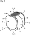
- FIGS. 2 . 4 and 7 show in perspective view an energy storage 16, which has a shape corresponding to two coaxially mounted, superimposed cylinders, with a longitudinal direction L parallel to the cylinder axes.
- the opposite and spaced flat surfaces of the cylinder form parallel end faces or end faces 28 of the energy accumulator 16. Die
- the lateral surfaces of the two cylinders form a circumferential region 30 of the energy store 16.
- the antenna element 18 is formed as a film structure 32 of a ferromagnetic or ferrimagnetic material, wherein by means of the antenna element 18, the end face of the end face 28 of the energy storage 16 partially, in particular more than half the end face of the end face 28 is covered.
- the antenna element 18 is designed as a ferrite foil.
- the film structure 32 on a first and second film element 34 and 36 and a third film element 38.
- the first and second film elements 34 and 36 are arranged parallel to the opposite end faces 28 of the energy accumulator 16 and thereby cover the end faces or end faces 28 of the energy store 16.
- the first film element 34 of the film structure 32 is identical in construction and symmetrical to the second film element 36, wherein the plane of symmetry extends perpendicular to the longitudinal direction L between the two film elements 34 and 36.
- the third film element 38 engages over the peripheral region 30 of the energy store 16 and extends transversely to the first and second film element 34 and 36 in the longitudinal direction L.
- the third film element 38 forms a coil core 40 of the antenna element 18 and is provided with a wire or coil winding 42.
- the wire or coil winding 42 is electrically contacted with electronics, not shown.
- the film elements 34, 36, 38 of the film structure form a U-shape, wherein the first and the second film element 34, 36 form the U-leg and the third film element 38, the connecting leg of the U-shape.
- the film elements 34, 36, 38 are preferably made flat.
- the first and second and the third film element 34, 36, 38 has a low film thickness perpendicular to the end faces 28 and the peripheral region 30 of the energy store 16 in relation to the expansion of the film elements 34, 36, 38 parallel to the end face of the end face 28 and to the peripheral region 30.
- a shield 44 is arranged in each case between the first and second film elements 34 and 36 of the film structure 32 of the antenna element 18 and the energy store 16.
- the shield 44 is formed of a dia- or paramagnetic material or contains dia- or paramagnetic material.
- the shield 44 is designed as a copper foil 46.
- the copper foil 46 is relatively cheap and easy to attach, which is why production costs are reduced.
- the shield 44 is at least partially covered by the first and second film elements 34 and 36 of the film structure 32.
- the film structure reduces the first and second film elements 34 and 36 with respect to the shield 44, so that a projection of the film structure onto the shield 44 along the longitudinal direction L, with the exception of a region in which the third film element 38 with the first and second film element 34, 35 of the antenna element 18 is completely encompassed by the shield 44.
- the hearing aid 4 can be designed to be particularly small. Alternatively, 4 additional components can be introduced into the hearing aid.
- a sensitivity and a quality of the antenna element 18 are adapted by the embodiment of the shield 44 and the embodiment of the first and second film element 34, 36 to the requirement in operation, wherein the antenna element 18 acts like a ferrite rod antenna with a comparatively large end face.
- the shield 44 Through the shield 44, a spreading of magnetic fields from the side of the first and second film elements 34 and 36 facing the energy store 16 to the energy store 16 is avoided. Rather, these are forced into the antenna element 18 and thus substantially extend there, whereby the sensitivity of the antenna element 18 is improved.
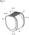
- the Figures 3 and 4 show the energy store 16 with the antenna element 18 and with the shield 44 in a representation according to Fig. 2 or in a side view.
- the peripheral region 30 of the energy store 16 is completely enclosed by its end faces 28 by a sleeve-like jacket 48.
- the jacket shield 48 is formed along the longitudinal direction L such that the entire peripheral region 30 of the energy accumulator 16 is covered by the jacket shield 48.
- the shroud 48 is disposed between the shield 44 attached to the first and second foil members 34 and 36, respectively, of the foil structure 32.
- the peripheral region 30 of the energy store 16 is only partially covered by the sleeve-like jacket 48.
- the jacket shield 48 is arranged centrally between the shielding 44 attached to the first and second film elements 34 and 36 and spaced therefrom. In both versions according to the Figures 3 and 4 the jacket shield 48 is arranged between the third film element 38 and the energy store 16.
- the jacket shield 48 is a component of the shield 44 and is preferably made of the material of the shield 44, which is arranged between the first and second film element 34 and 36 and the energy store 16.
- the shroud 44 is designed here as a copper foil.
- Fig. 5 shows in a plan view arranged on a flexible printed circuit board 50 antenna element 18 with the first and second film element 34 and 36 and the wire or coil winding 42 around the coil core 40 designed as third film element 38 in a flat embodiment prior to assembly.
- the flexible printed circuit board 50 in this case has a first region 52, a second region 54 and a third region 56, wherein the first, second and third regions 52, 54 and 56 are formed integrally. At these, the first, the second and the third film element 34, 36 and 38 of the film structure 32 are arranged.
- the shield 44 is designed as a copper layer of the flexible printed circuit board 50, whereby a simple and stable production of the shield is given.
- the first and second film element of the film structure and the regions of the flexible printed circuit board 54 and 56 arranged thereon are suitably bent.
- the first and second film elements 34 , 36 of the film structure 30 and the first and second regions 52, 54 of the flexible printed circuit board 50 are arranged on the end faces 28 of the energy carrier 16.
- the energy storage 16 facing printed circuit board 50 covers the end faces 28 of the energy carrier 16 completely.
- Fig. 6 shows in plan view of the film structure 32 facing away from or in the assembled state of the energy storage 16 side facing the flexible circuit board 50 from Fig. 5 ,
- electronic hearing aid components 60 for example, a component of the transmitting and / or receiving unit 19, a charging electronics or connections for the energy storage 16. They are in the first and second areas 52 and 54 of the flexible printed circuit board 50 mounted substantially centrally , Due to the shield 44, the electronic components 60 are shielded from magnetic fields, and Disturbances of the antenna element 18 due to any magnetic fields caused by operation in the hearing aid component 60 are reduced.
- Fig. 7 3 shows a perspective view of the first and second film elements 34, 36 arranged on the end faces 28 of the energy store 16 and a hearing device circuit board 62.
- the first and second film elements 34, 36 of the film structure are adjacent to a first area 64 and a second area 66 of the hearing device board 62, respectively arranged.
- the board areas 64, 66 of the hearing device board 62 are arranged on the end faces 28 of the energy store 16, wherein the shield 44 are designed as copper layers 58 of the board or circuit board 62.
- the third film element 38, which forms the spool core 40 of the antenna element 18, is here integrated in a third region 68 of the hearing device board 62. This carries further components 70 of the hearing aid 4, in particular amplifier circuits and / or electronic components.
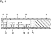
- Fig. 8 shows in a sectional view of the region of the third portion 68 of the hearing aid board 62 between the lines VIII-VIII of the Fig. 7 ,
- the third film element 38 of the film structure 32 which forms the spool core 40 of the antenna element 18, is integrated in the hearing device circuit board 62.
- the wire or coil winding 42 is formed by means of plated-through holes 72 electrically contacted tracks of the hearing aid device 62, whereby a complex and sensitive winding of the wire or coil winding 42 is avoided.
- the shield 44 is embodied by means of the copper layer 58 of the hearing aid circuit board 50.
Abstract
Description
- Die Erfindung betrifft ein Hörgerät, insbesondere Hinter-dem-Ohr-Hörhilfegerät, mit einer Sende- und/oder Empfangseinheit mit einem Antennenelement zur drahtlosen Funkkommunikation sowie zur induktiven Energieübertragung eines Energiespeichers. Das Hörgerät ist bevorzugt ein Hörhilfegerät.
- Personen, die unter einer Verminderung des Hörvermögens leiden, verwenden ein Hörgerät als Hilfsinstrument oder Hörhilfegerät. Dabei wird der Schall oder ein Schallsignal der Umgebung über einen elektromechanischen Schallwandler erfasst, der den Schall bzw. das Schallsignal in ein elektrisches Signal (Audiosignal) wandelt. Das elektrische Signal wird mittels einer Verstärkerschaltung bearbeitet und mittels eines weiteren elektromechanischen Wandlers in ein verstärktes Schallsignal umgewandelt, das in den Gehörgang der Person eingeleitet wird.
- Es sind unterschiedliche Ausführungen von Hörgeraten bekannt. So werden sogenannte "Hinter-dem-Ohr-Geräte" zwischen Schädel und Ohrmuschel getragen, wobei das verstärkte Schallsignal mittels eines Schallschlauchs in den Gehörgang der Person eingeleitet wird. Eine weitere Ausführung eines Hörgeräts ist ein "Im-Ohr-Gerät", bei dem das Hörgerät selbst in den Gehörgang eingebracht wird. In Folge dessen wird der Gehörgang zumindest teilweise verschlossen, so dass mit Ausnahme des mittels des Hörgeräts erzeugten Schallsignals kein weiterer Schall oder lediglich stark gedämpfter Schall in den Gehörgang eindringen kann.
- Sofern die Person unter einer Beeinträchtigung des Hörvermögens beider Ohren leidet, wird ein Hörgerätesystem mit zwei derartigen Hörgeräten als Hörhilfegeräte verwendet, wobei jedem Ohr jeweils eines der beiden Hörgeräte zugeordnet ist. Um der Person ein räumliches Hören zu ermöglichen, ist es erforderlich, dass die mit einem Hörgerät erfassten Audiosignale dem jeweils anderen Hörgerät zur Verfügung gestellt werden. Eine typischerweise drahtlose Funkkommunikation zwischen den beiden Hörgeräten erfolgt dabei mittels einer Antenne (Antennenelement).
- Das jeweilige Hörgerät wird mittels eines in ein Gerätegehäuse eingebrachten und wiederaufladbaren Energiespeichers betrieben. Das Hörgerät kann zum Zwecke des Ladens des Energiespeichers in eine Ladestation eingebracht werden, die induktiv mit einer Ladevorrichtung des Hörgeräts gekoppelt ist und somit Energie drahtlos an den Energiespeicher überträgt. Dabei werden beim Ladevorgang auf Grund eines magnetischen Wechselfeldes in den metallischen Schalen des Energiespeichers Wirbelströme induziert, die eine unerwünschte Wärmeentwicklung bedingen.
- Der Erfindung liegt die Aufgabe zugrunde, ein besonders geeignetes Hörgerät anzugeben, bei dem der Energiespeicher mit möglichst raumsparenden Mitteln induktiv geladen wird. Dabei soll insbesondere eine Wärmeentwicklung im Energiespeicher durch Wirbelstromverluste auf Grund des magnetischen Wechselfeldes möglichst vermieden werden.
- Diese Aufgabe wird erfindungsgemäß gelöst durch die Merkmale des Anspruchs 1. Vorteilhafte Ausgestaltungen und Weiterbildungen sind Gegenstand der Unteransprüche.
- Das Hörgerät ist vorzugsweise ein Hörhilfegerät mit einem Gerätegehäuse und mit einer darin angeordneten (gehäuseinternen) Sende- und/oder Empfangseinheit, die ein mit einer Elektronik, beispielsweise mit einem integrierten Schaltkreis zur Signalverarbeitung, elektrisch kontaktiertes Antennenelement aufweist. Das Antennenelement dient zur drahtlosen Signalübertragung, insbesondere zur Funkkommunikation mit einem zweiten Hörgerät, so dass die beiden Hörgeräte zumindest zeitweise signaltechnisch miteinander gekoppelt sind. Mittels der Funkkommunikation werden insbesondere Daten- und/oder Einstellungen zwischen den beiden Hörgeräten übertragen, wobei die Datenübertragung zweckmäßigerweise induktiv erfolgt.
- Alternativ oder in Kombination kann dem Hörgerät eine Fernbedienung zugeordnet sein, die zur drahtlosen Funkkommunikation signaltechnisch mit dem Hörgerät oder gegebenenfalls mit den beiden Hörgeräten gekoppelt ist. Hierbei erfolgt zweckmäßigerweise wiederum eine induktive Übertragung von Daten, wie beispielsweise Konfigurationsdaten.
- Insbesondere ist das oder jedes der Hörgeräte dafür vorgesehen und eingerichtet, zumindest teilweise in den Gehörgang eines Benutzers eingeführt zu werden. Zur Energieversorgung des Hörgeräts dient ein wiederaufladbarer Energiespeicher, beispielsweise ein Lithium-Ionen-Akkumulator, der im Gerätegehäuse bzw. im Hörgerät angeordnet oder in dieses eingebracht ist. Dabei dient das Antennenelement zusätzlich zur induktiven Energieübertragung, so dass in einem bestimmten Betriebsmodus mittels des Antennenelements ein drahtloses Laden des Energiespeichers des Hörgeräts ermöglicht ist.
- Der Energiespeicher weist im Wesentlichen parallele und zueinander beabstandete Stirnseiten (Stirnseitenflächen) und einen Umfangsbereich auf, der aus geeigneter Weise einer umlaufenden, zu den Stirnseitenflächen des Energiespeichers senkrechten Mantelfläche gebildet ist.
- Das Antennenelement ist als eine Folienstruktur ausgebildet und umgreift den Energiespeicher zumindest abschnittsweise. Die Folienstruktur weist dazu ein erstes und ein zweites sowie ein drittes Folienelement auf. Dabei sind das erste und das zweite Folienelement jeweils an den Stirnseiten des Energiespeichers angeordnet.
- In einer geeigneten Weiterbildung überdecken das erste und/oder das zweite Folienelement zumindest teilweise die Stirnseitenfläche der jeweiligen Stirnseite. Das erste und/oder zweite Folienelement kann dabei beispielsweise eine Ringform aufweisen. Vorzugsweise überdecken das erste und/oder das zweite Folienelement mindestens die halbe Stirnseitenfläche der jeweiligen Stirnseiten des Energiespeichers und sind dabei bevorzugt flächig ausgeführt. In anderen Worten weist das erste und zweite Folienelement im Verhältnis zu deren Ausdehnung parallel zur Stirnfläche eine geringe Foliendicke (senkrecht zu den Stirnseiten des Energiespeichers) auf.
- Das dritte Folienelement verläuft im Einbauzustand quer zum ersten und zweiten Folienelement und übergreift vorzugsweise nur einen vergleichsweise kleinen Abschnitt des Umfangsbereichs des Energiespeichers. Dabei bildet das dritte Folienelement zweckmäßigerweise einen sich in Querrichtung zum ersten und zweiten Folienelement erstreckenden Spulenkern des Antennenelements. Der Spulenkern des Antennenelements ist mit einer Draht- oder Spulenwicklung aus einer Anzahl von Windungen versehen.
- Die Windungen der Draht- oder Spulenwicklung können den Spulenkern umfangsseitig zum Beispiel entlang der vollständigen Ausdehnung in Querrichtung, d. h. in Längsrichtung des dritten Folienelementes umgeben. Bevorzugt jedoch ragt der Spulenkern aus der Draht- oder Spulenwicklung zumindest einseitig, vorzugsweise beidseitig, heraus. Geeigneter Weise ist die Draht- oder Spulenwicklung mit einer Elektronik elektrisch kontaktiert. Das Antennenelement bildet dabei eine Sekundärspule eines Transformators.
- In vorteilhafter Ausgestaltung sind das erste, zweite und dritte Folienelement der Folienstruktur zusammenhängend ausgebildet. In einer denkbaren Ausführungsform können die Folienelemente auch aus Einzelteilen hergestellt sein, welche beispielsweise erst im Montageendzustand miteinander verbunden sind.
- Auf Grund der Anordnung des ersten und des zweiten Folienelements an den im Wesentlichen parallel orientierten Stirnflächen des Energiespeichers und in Folge der Anordnung des dritten Folienelements am zu den Stirnflächen im Wesentlichen senkrechten Umfangsbereich des Energiespeichers, bildet das Antennenelement eine U-Form. Hierbei ist auf Grund der Abwinklung (Faltung) des ersten Folienelements und des zweiten Folienelements gegenüber dem dritten Folienelement und der Draht- oder Spulenwicklung sowie auf Grund der Ausbildung des Antennenelementes als Folie mit möglichst geringer Foliendicke der Platzbedarf verringert, so dass ein vergleichsweise kompaktes Antennenelement bereitgestellt ist, welches somit auch im nur wenig Bauraum bietenden Gerätegehäuse des Hörgerätes untergebracht werden kann.
- Das Antennenelement ist aus einem ferromagnetischen und/oder ferrimagnetischen Material gefertigt. Geeigneter Weise ist das Antennenelement aus einem Ferrit gebildet. Vorteilhaft bestehen das erste Folienelement und das zweite Folienelement des folienartigen Antennenelements aus dem gleichen Material wie das dritte Folienelement.
- In einer geeigneten Weiterbildung ist zwischen der Folienstruktur des Antennenelements und dem Energiespeicher eine Abschirmung angeordnet, insbesondere zwischen dem ersten Folienelement und dem Energiespeicher sowie zwischen dem zweiten Folienelement und dem Energiespeicher. Dabei ist die Abschirmung aus einem diamagnetischen und/oder paramagnetischen Material gebildet oder enthält diamagnetisches und/oder paramagnetisches Material mit vorzugsweise hoher Leitfähigkeit, beispielsweise Kupfer oder Aluminium Die Abschirmung ist geeigneter Weise ebenfalls eine Folie oder mittels einer Folie gebildet.
- Vorteilhafter Weise weist das Antennenelement eine hohe Sensitivität und eine hohe Güte auf, wobei das Antennenelement nach Art einer Ferritstabantenne mit einer vergleichsweise großen Stirnfläche wirkt. Durch die Abschirmung ist ein Ausbreiten der Magnetfeldlinien von der dem Energiespeicher zugewandten Seite des ersten und zweiten Folienelements zum Energiespeicher hin vermieden. Vorzugsweise ist die Permeabilität der Folienstruktur des Antennenelements größer als die Permeabilität der Abschirmung, und die elektrische Leitfähigkeit des Materials der Abschirmung ist zweckmäßiger Weise größer als die elektrische Leitfähigkeit der Folienstruktur des Antennenelements. Infolgedessen werden Wirbelströme allenfalls und nur geringfügig in der Abschirmung hervorgerufen, wohingegen die Magnetfeldlinien in die Folienstruktur in das Antennenelement hineingedrängt werden und somit im Wesentlichen dort verlaufen. Aufgrund dessen sind die effektive Permeabilität und die Sensitivität des Antennenelements erhöht.
- In einer bevorzugten Ausführung deckt die Abschirmung die Stirnseiten des Energiespeichers vollständig ab. Die Abschirmung ist dabei von der Folienstruktur des Antennenelements zumindest teilweise abgedeckt. Mit anderen Worten ist mit Ausnahme desjenigen Bereichs, in dem das dritte Folienelement mit dem ersten und zweiten Folienelement des Antennenelements gekoppelt ist, die Abschirmung von der Folienstruktur des Antennenelements vollständig abgedeckt. Der Umfang des Antennenelements fluchtet somit mit dem Umfang der Abschirmung. Alternativ ist die Folienstruktur gegenüber der Abschirmung verkleinert, so dass eine Projektion der Folienstruktur auf die Abschirmung von dieser vollständig überdeckt ist.
- Die Sensitivität und die Güte des Antennenelements sind durch die Ausführung der Folienstruktur gegenüber der Abschirmung an betriebsgemäß auftretende Anforderungen anpassbar. Beispielsweise bedingt eine gegenüber der Abschirmung verkleinerte erste und zweite Folienstruktur eine verbesserte Güte des Antennenelements bei verringerter Sensitivität. Zusätzlich kann zwischen dem dritten Folienelement und dem Energiespeicher eine Abschirmung angeordnet sein, wodurch die Sensitivität und die Güte des Antennenelements an betriebsgemäß auftretende Anforderungen weiter anpassbar sind.
- Durch die Abschirmung sowie durch die Folienstruktur ist ein Ausbreiten der Magnetfeldlinien von der dem Energiespeicher zugewandten Seite des ersten und zweiten Folienelements zum Energiespeicher hin vermieden. Dabei werden Wirbelstromverluste durch ein betriebsbedingtes, insbesondere ein durch den Ladevorgang des Energiespeichers bedingtes, magnetisches Wechselfeld allenfalls und nur geringfügig in der Abschirmung hervorgerufen. In Folge dessen sind Wirbelstromverluste und eine durch diese hervorgerufene Erwärmung im zwischen der Abschirmung angeordneten Energiespeicher besonders vorteilhaft vermieden, wodurch Schäden am Energiespeicher vermieden sind und eine erhöhte Lebensdauer des Energiespeichers gegeben ist.
- Durch das Anordnen des Antennenelements praktisch direkt am Energiespeicher, und durch das Anordnen der Abschirmung zwischen der Folienstruktur des Antennenelements und dem Energiespeicher ist eine platzsparende Ausführungsform gebildet. In Folge dessen kann das Hörgerät kleiner ausgeführt, oder in das Hörgerät können zusätzliche Komponenten eingebracht werden. Wenn der Energiespeicher aus dem Material der Abschirmung gebildet ist, muss keine separate Abschirmung zur Einbringung zwischen der Folienstruktur und dem Energiespeicher bereitgestellt werden.
- Vorteilhafter Weise sind das erste und zweite Folienelement der Folienstruktur des Antennenelements und die Abschirmung flächig und somit besonders wirksam ausgeführt. Des Weiteren werden durch die Abschirmung die Magnetfeldlinien in das Antennenelement hineingedrängt und verlaufen im Wesentlichen im Antennenelement. Zusätzlich sind auf Grund der größeren Permeabilität des Antennenelements gegenüber der Abschirmung sowie der größeren Leifähigkeit der Abschirmung gegenüber dem Antennenelement Wirbelstromverluste im Antennenelement vermieden. Die Sensitivität und die Güte des Antennenelements sind dadurch vorteilhaft verbessert. In Folge dessen ist die Energieübertragung mittels des magnetischen Wechselfeldes an den Energiespeicher verbessert, und die Ausrichtung oder Positionierung des Hörgeräts bezüglich des Ladegeräts kann beliebiger sein.
- In einer denkbaren Ausführungsform sind das erste und das zweite Folienelement der Folienstruktur über weitere Bereiche des Hörgeräts, beispielsweise auch über das vollständige Hörgerät, angeordnet. Auf Grund der folienartigen Ausführung ist dadurch das Antennenelement platzsparend und kostengünstig vergrößert, wodurch eine Bandbreite sowie die Güte und Sensitivität des Antennenelements an die betriebsgemäßen Anforderungen angepasst werden kann.
- In einer geeigneten Weiterbildung ist die Abschirmung in eine insbesondere flexible Leiterplatte integriert. Die flexible Leiterplatte weist dabei drei zusammenhängende Bereiche auf, an denen das erste, das zweite und/oder das dritte Folienelement der Folienstruktur angeordnet sind. Vorteilhafter Weise trägt die Leiterplatte dabei an der dem Energiespeicher zugewandten Plattenfläche eine elektronische Hörgerätekomponente, insbesondere der Sende- und/oder Empfangseinheit, oder beispielsweise eine Ladeelektronik in Form eines Ladechips, einen Funksystemchip und/oder Anschlüsse für den Energiespeicher.
- Die Hörgerätekomponente ist dabei geeigneter Weise auf der dem Energiespeicher zugewandten Plattenfläche im Wesentlichen zentral auf einem Bereich der Leiterplatte angeordnet, an dem das erste und zweite Folienelement der Folienstruktur des Antennenelements anliegen. Dadurch ist die Hörgerätekomponente im Wesentlichen feldfrei positioniert und wird aufgrund der Magnetfelder nicht oder lediglich in einem geringen Maß gestört. Auch stört eine derartige Hörgerätekomponente ein Signal-Rausch-Verhältnis der Antenne bei Betrieb nicht oder lediglich in einem vergleichsweise geringen Maße, d.h. die Antenne und die Hörgerätekomponente weisen ein vergleichsweise geringes Übersprechen auf.
- Insbesondere werden aufgrund der Abschirmung etwaige Magnetfelder abgeschirmt, die beispielsweise aufgrund eines stromdurchflossenen elektrischen Leiters oder einer Leiterbahn der Hörgerätekomponente hervorgerufen werden. Vorteilhaft ist durch die Integration der Abschirmung in eine insbesondere flexible Leiterplatte eine stabile Herstellung der Abschirmung gegeben. Zusätzlich ist die Hörgerätekomponente einfach und kostengünstig auf die Leiterplatte aufbringbar, beispielsweise durch Reflow-Löten.
- Besonders vorteilhaft ermöglichen die Bildung des Antennenelements aus einer flexiblen Folie und das Einbringen der Abschirmung in eine flexible Leiterplatte eine einfache und fehlersichere Montage des Antennenelements und der Abschirmung. Die Montage erfolgt dabei ausgehend von einer planen Form durch Abwinkeln des ersten und zweiten Folienelements der Folienstruktur sowie der daran angeordneten Abschirmung. Das Abwinkeln (Knicken oder Falten) des ersten und zweiten Folienelements der Folienstruktur und der daran angeordneten Bereiche der flexiblen Leiterplatte erfolgt derart, dass das erste und zweite Folienelement der Folienstruktur sowie die Abschirmung an den Stirnseiten des Energieträgers anliegen.
- In zweckmäßiger Ausgestaltung ist die Folienstruktur des Antennenelements zumindest teilweise in eine zumindest eine der Hörgerätekomponenten tragende Leiterplatte (Platine) integriert. Insbesondere ist das dritte Folienelement der Folienstruktur in die Platine eingebracht. Die Draht- oder Spulenwicklung um das den Spulenkern des Antennenelements bildende dritte Folienelement ist dabei aus Leiterbahnen der Platine hergestellt, wodurch eine aufwendige und empfindliche Wicklung der Draht- oder Spulenwicklung vermieden ist.
- Gemäß einer vorteilhaften Ausführungsform ist der Energiespeicher zumindest teilweise von einem manschettenartigen Mantelschirm umgeben. In anderen Worten weist der Mantelschirm eine Breite auf, welche maximal der Breite des Umfangsbereichs. Der Mantelschirm ist dabei mittig zwischen die an dem ersten und dem zweiten Folienelement angebrachte Abschirmung angeordnet und dabei nicht zwingend (elektrisch) geschlossen. Der Mantelschirm ist zwischen der an den ersten und zweiten Folienelementen der Folienstruktur angebrachten Abschirmung sowie zwischen dem dritten Folienelement und dem Energiespeicher angeordnet. Der Mantelschirm ist vorzugsweise Bestandteil der Abschirmung, jedoch nicht zwingend mit diesem (galvanisch) verbunden.
- Durch den Mantelschirm ist ein Eindringen der Magnetfeldlinien in den Energiespeicher vermieden, so dass Wirbelstromverluste durch ein, insbesondere während eines Ladevorgang des Energiespeichers, betriebsbedingtes magnetisches Wechselfeld allenfalls und nur geringfügig in der Abschirmung hervorgerufen werden. In Folge dessen sind Wirbelstromverluste und eine durch diese hervorgerufene Erwärmung des Energiespeichers mittels des zusätzlichen Mantelschirms besonders vorteilhaft vermieden. Auf Grund der manschettenartigen Ausführung des Mantelschirms ist zudem eine einfache Auswechselbarkeit des Energiespeichers sicher gestellt.
- Die mit der Erfindung erzielten Vorteile bestehen insbesondere darin, dass durch die besonders geeignete Anordnung und Ausgestaltung des Antennenelements sowie gegebenenfalls der Abschirmung um den Energiespeicher beim induktiven und kabellosen Ladevorgang des Hörgeräts die Wärmeentwicklung im Energiespeicher des Hörgeräts auf Grund von Wirbelstromverlusten des magnetischen Wechselfeldes vermieden ist. Des Weiteren ist der Platzbedarf im Gerätegehäuse und somit im Hörgerät verringert. In der Folge kann das Hörgerät kleiner ausgeführt, oder es können zusätzliche Komponenten für weitere Funktionalitäten verbaut werden.
- Das Hörgerät kann beispielsweise ein receiver-in-the-canal-Hörhilfegerät (RIC-Hörhilfegerät), ein Im-Ohr-Hörhilfegerät (in-the-ear-(ITE)Hörhilfegerät), ein in-the-canal-Hörhilfegerät (ITC) oder ein complete-in-canal-Hörhilfegerät (CIC) sein. Besonders bevorzugt ist das Hörhilfegerät ein Hinter-dem-Ohr-Hörhilfegerät (behind-the-ear-(BTE) Hörhilfegerät), das hinter einer Ohrmuschel getragen wird. Das Hörgerät kann Teil eines (binauralen) Hörgerätesystems sein, wobei jedem Ohr einer Person jeweils ein derartiges Hörgerät zugeordnet ist und Daten mittels drahtloser Funkkommunikation zwischen den Hörgeräten übertragen werden können.
- Nachfolgend werden Ausführungsbeispiele der Erfindung anhand einer Zeichnung näher erläutert. Darin zeigen:
- Fig. 1
- schematisch ein Hörgerätesystem mit zwei jeweils einen Energiespeicher und ein Antennenelement umfassenden Hörgeräten,
- Fig. 2
- in einer perspektivischen Ansicht den vom Antennenelement und von einer Abschirmung stirnseitig abgedeckten Energiespeicher,
- Fig. 3
- in einer Darstellung gemäß
Figur 2 den zusätzlich von einem Mantelschirm manschettenartig umfangsseitig umschlossenen Energiespeicher, - Fig. 4
- in einer Seitenansicht den Energiespeicher gemäß
Fig. 3 mit nur teilweise umfasstem Umfangsbereich, - Fig. 5
- in Draufsicht das auf einer flexiblen Leiterplatte angeordnete folienartige Antennenelement mit beidseitig eines eine Draht- oder Spulenwicklung tragenden Spulenkerns einem ersten und zweiten Folienelement,
- Fig. 6
- die flexible Leiterplatte gemäß
Fig. 5 in einer Rückansicht auf die im Montagezustand dem Energiespeicher zugewandte Plattenrückseite mit elektronischen Komponenten einer Sende- und/oder Empfangseinheit des Hörgerätes, - Fig. 7
- in perspektivischer Ansicht eine elektronische Komponenten tragende Hörgeräteplatine, in welche das Antennenelement teilweise integriert ist, und
- Fig. 8
- einen vergrößerten Ausschnitt der Hörgeräteplatine entlang der Schnittlinie VIII-VIII der
Fig. 7 mit einem dritten Folienelement des Antennenelements einer Kupferlage der Platine. - Einander entsprechende Teile sind in allen Figuren mit den gleichen Bezugszeichen versehen.
- In
Fig. 1 ist ein (binaurales) Hörhilfesystem 2 mit zwei baugleichen Hörgeräten 4 dargestellt. Die Hörgeräte 4 sind als Hörhilfegerät dazu vorgesehen und eingerichtet, hinter jeweils einem Ohr eines Benutzers (Träger) getragen zu werden. Mit anderen Worten handelt es sich jeweils um Hinter-dem-Ohr-Hörgeräte (BTE - Hörgerät), welches einen nicht dargestellten Schallschlauch aufweist, der in das Ohr eingeführt wird. Das jeweilige Hörgerät 4 umfasst ein beispielsweise aus einem Kunststoff gefertigtes Gehäuse 6. Innerhalb des Gehäuses 6 ist ein Mikrofon 8 mit zwei elektromechanischen Schallwandlern 10 angeordnet. Mittels der beiden Schallwandler 10 ist es ermöglicht, eine Richtcharakteristik des Mikrofons 8 zu verändern, indem ein zeitlicher Versatz elektrischer Signale verändert wird, welche mittels des jeweiligen Schallwandlers 10 aus erfassten Schallsignalen generiert werden. Die beiden elektromechanischen Schallwandler 10 sind mit einer Signalverarbeitungseinheit 12 signaltechnisch gekoppelt, die eine Verstärkerschaltung umfasst. Die Signalverarbeitungseinheit 12 weist elektrische und/oder elektronische (aktive und/oder passive) Bauteile und Schaltungselemente auf. - Ferner ist mit der Signalverarbeitungseinheit 12 ein Lautsprecher 14 signaltechnisch gekoppelt, mittels dessen die durch die Signalverarbeitungseinheit 12 bearbeiteten elektrischen Signale des Schallwandlers 10 erneut als Schallsignale ausgegeben werden. Diese Schallsignale werden mittels des nicht näher dargestellten Schallschlauchs in das Ohr eines Benutzers des Hörgerätesystems 2 geleitet.
- Die Leistungsversorgung (Spannungs- und Stromversorgung) der Signalverarbeitungseinheit 12, des Mikrofons 8 und des Lautsprechers 14 jedes Hörgeräts 4 erfolgt mittels eines wiederaufladbaren (strichliniert dargestellten) Energiespeichers 16. Jedes der Hörgeräte 4 weist ferner ein Antennenelement 18 einer Sende- und/oder Empfangseinheit 19 auf, mittels derer eine drahtlose Funkkommunikation 20 zwischen den beiden Hörgeräten 4 ermöglicht ist. Das Antennenelement 18 umgreift dabei den Energiespeicher 16 teilweise. Die drahtlose Funkkommunikation 20 dient dem Austausch von Daten und erfolgt induktiv. Aufgrund des Austauschs der Daten ist es beispielsweise ermöglicht, dem Träger der Hörgeräte 4 ein räumliches Hörgefühl zu vermitteln.
- In der Ausführung der
Fig. 1 ist ferner ein weiteres Gerät 22 dargestellt, welches beispielsweise eine Fernbedienung oder ein Smartphone ist. Dieses weist eine nicht näher dargestellte Kommunikationseinrichtung auf, mit denen eine weitere, mittels der strichpunktierten Pfeile 24 angedeutete drahtlose Funkkommunikation mit den beiden Antennenelementen 18 der beiden Hörgeräte 4 erstellt ist. Die drahtlose Funkkommunikation dient dem Austausch von Daten zwischen dem weiteren Gerät 22 und den Hörgeräten 4. - Zusätzlich wird das Antennenelement 18 zur induktiven und drahtlosen Energieübertragung, symbolisiert durch die strichpunktierten Pfeile 26, von einem Ladegerät 27 an das Hörgerät 4 herangezogen, so dass in einem bestimmten Betriebsmodus mittels des Antennenelements 18 ein Laden des wiederaufladbaren Energiespeichers 16 des Hörgeräts 4 ermöglicht ist. Mit anderen Worten wird mittels des Antennenelements 18 induktiv Energie übertragen, welche zum Laden des Energiespeichers 16 genutzt wird.
- Die
Figuren 2 ,4 und7 zeigen in perspektivischer Ansicht einen Energiespeicher 16, welcher eine Form aufweist, die zwei koaxial gelagerten, aufeinander angeordneten Zylindern entspricht, mit einer Längsrichtung L parallel zu den Zylinderachsen. Die gegenüberliegenden und beabstandeten ebenen Flächen der Zylinder bilden parallele Stirnseiten oder Stirnflächen 28 des Energiespeichers 16. Die Mantelflächen der beiden Zylinder bilden einen Umfangsbereich 30 des Energiespeichers 16. - Das Antennenelement 18 ist als eine Folienstruktur 32 aus einem ferro- oder ferrimagnetischen Material gebildet, wobei mittels des Antennenelements 18 die Stirnfläche der Stirnseite 28 des Energiespeichers 16 teilweise, insbesondere mehr als die halbe Stirnfläche der Stirnseite 28, abgedeckt ist. In
Fig. 2 ist das Antennenelement 18 als eine Ferritfolie ausgeführt. Dabei weist die Folienstruktur 32 ein erstes und zweites Folienelement 34 bzw. 36 sowie ein drittes Folienelement 38 auf. Das erste und zweite Folienelement 34 und 36 sind an den gegenüberliegenden Stirnseiten 28 des Energiespeichers 16 parallel angeordnet und überdecken dabei die Stirnseiten bzw. Stirnflächen 28 des Energiespeichers 16. - Das erste Folienelement 34 der Folienstruktur 32 ist baugleich und symmetrisch zum zweiten Folienelement 36, wobei die Symmetrieebene senkrecht zur Längsrichtung L zwischen den beiden Folienelementen 34 und 36 verläuft. Das dritte Folienelement 38 übergreift den Umfangsbereich 30 des Energiespeichers 16 und verläuft quer zum ersten und zweiten Folienelement 34 und 36 in Längsrichtung L. Das dritte Folienelement 38 bildet dabei einen Spulenkern 40 des Antennenelements 18 und ist mit einer Draht- oder Spulenwicklung 42 versehen. Die Draht- oder Spulenwicklung 42 ist mit einer nicht dargestellten Elektronik elektrisch kontaktiert. Die Folienelemente 34, 36, 38 der Folienstruktur bilden eine U-Form, wobei das erste und das zweite Folienelement 34, 36 die U-Schenkel und das dritte Folienelement 38 den Verbindungsschenkel der U-Form bilden.
- Die Folienelemente 34, 36, 38 sind bevorzugt flächig ausgeführt. In anderen Worten weist das erste und zweite sowie das dritte Folienelement 34, 36, 38 eine geringe Foliendicke senkrecht zu den Stirnseiten 28 beziehungsweise zum Umfangsbereich 30 des Energiespeichers 16 im Verhältnis zur Ausdehnung der Folienelemente 34, 36, 38 parallel zur Stirnfläche der Stirnseite 28 beziehungsweise zum Umfangsbereich 30 auf.
- Des Weiteren ist jeweils zwischen dem ersten und zweiten Folienelement 34 und 36 der Folienstruktur 32 des Antennenelements 18 und dem Energiespeicher 16 eine Abschirmung 44 angeordnet. Die Abschirmung 44 ist aus einem dia- oder paramagnetischen Material gebildet oder enthält dia- oder paramagnetisches Material.
- Im Ausführungsbeispiel der
Fig. 2 ist die Abschirmung 44 als eine Kupferfolie 46 ausgeführt. Die Kupferfolie 46 ist vergleichsweise günstig und einfach anbringbar, weswegen Herstellungskosten reduziert sind. Die Abschirmung 44 ist vom ersten und zweiten Folienelement 34 und 36 der Folienstruktur 32 zumindest teilweise überdeckt. - Dabei ist im Ausführungsbeispiel der
Fig. 2 die Folienstruktur das erste und zweite Folienelement 34 und 36 verkleinert gegenüber der Abschirmung 44, so dass eine Projektion der Folienstruktur auf die Abschirmung 44 entlang der Längsrichtung L, mit Ausnahme eines Bereichs, in dem das dritte Folienelement 38 mit dem ersten und zweiten Folienelement 34, 35 des Antennenelements 18 gekoppelt ist, vollständig von der Abschirmung 44 umfasst ist. - Durch das Anordnen des Antennenelements 18 direkt am Energiespeicher 16 und durch das Anordnen der Abschirmung 44 zwischen der Folienstruktur 32 des Antennenelements 18 und dem Energiespeicher 16 ist eine platzsparende Ausführungsform gebildet. In Folge dessen kann das Hörhilfegerät 4 besonders klein ausgeführt sein. Alternativ können in das Hörhilfegerät 4 zusätzliche Komponenten eingebracht werden.
- Eine Sensitivität und eine Güte des Antennenelements 18 sind durch die Ausführungsform der Abschirmung 44 und die Ausführungsform des ersten und zweiten Folienelements 34, 36 auf die im Betrieb nötigen Anforderung angepasst, wobei das Antennenelement 18 nach Art einer Ferritstabantenne mit einer vergleichsweise großen Stirnfläche wirkt. Durch die Abschirmung 44 ist dabei ein Ausbreiten von Magnetfeldern von der dem Energiespeicher 16 zugewandten Seite des ersten und zweiten Folienelements 34 und 36 zum Energiespeicher 16 hin vermieden. Vielmehr werden diese in das Antennenelement 18 hineingedrängt und verlaufen somit im Wesentlichen dort, wodurch die Sensitivität des Antennenelements 18 verbessert ist.
- Die
Figuren 3 und4 zeigen den Energiespeicher 16 mit dem Antennenelement 18 und mit der Abschirmung 44 in einer Darstellung gemäßFig. 2 bzw. in einer Seitenansicht. Bei der inFig. 3 gezeigten Ausführung ist der Umfangsbereich 30 des Energiespeichers 16 zwischen dessen Stirnseiten 28 von einem manschettenartigen Mantelschirm 48 vollständig umfasst. In anderen Worten ist der Mantelschirm 48 entlang der Längsrichtung L derart gebildet, dass der gesamte Umfangsbereich 30 des Energiespeichers 16 vom Mantelschirm 48 abgedeckt ist. Der Mantelschirm 48 ist zwischen der an den ersten und zweiten Folienelementen 34 bzw. 36 der Folienstruktur 32 angebrachten Abschirmung 44 angeordnet. - Gemäß der Ausführungsform nach
Fig. 4 ist der Umfangsbereich 30 des Energiespeichers 16 nur teilweise vom manschettenartigen Mantelschirm 48 umfasst. Der Mantelschirm 48 ist dabei mittig zwischen die an dem ersten und zweiten Folienelement 34 und 36 angebrachte Abschirmung 44 und beabstandet zu dies angeordnet. In beiden Ausführungen gemäß denFiguren 3 und4 ist der Mantelschirm 48 zwischen dem dritten Folienelement 38 und dem Energiespeicher 16 angeordnet. - Der Mantelschirm 48 ist ein Bestandteil der Abschirmung 44 und ist vorzugsweise aus dem Material der Abschirmung 44, welche zwischen dem ersten bzw. zweiten Folienelement 34 bzw. 36 und dem Energiespeicher 16 angeordnet ist. Der Mantelschirm 44 ist hier als eine Kupferfolie ausgeführt.
- Mittels der Folienstruktur 32 sowie mittels der Abschirmung 44 zwischen dem ersten und/oder zweiten Folienelement 34, 36 und dem Energiespeicher 16 und mittels des Mantelschirms 48 ist ein Eindringen von Magnetfeldern in den Energiespeicher 16 vermieden, so dass Wirbelstromverluste des magnetisches Wechselfeld allenfalls und nur geringfügig in der Abschirmung 44 hervorgerufen werden. In Folge dessen ist eine Erwärmung des Energiespeichers 16 vermieden. Auf Grund der manschettenartigen Ausführung des Mantelschirms 48 ist des Weiteren die Auswechselbarkeit des Energiespeichers 16 erhalten.
-
Fig. 5 zeigt in einer Draufsicht das auf einer flexiblen Leiterplatte 50 angeordnete Antennenelement 18 mit dem ersten und zweiten Folienelement 34 bzw. 36 sowie die Draht- oder Spulenwicklung 42 um das als Spulenkern 40 ausgeführte dritte Folienelement 38 in flacher Ausführungsform vor der Montage. Die flexible Leiterplatte 50 weist dabei einen ersten Bereich 52, einen zweiten Bereich 54 sowie einen dritten Bereich 56 auf, wobei der erste, der zweite und der dritte Bereich 52, 54 und 56 zusammenhängend gebildet sind. An diesen sind das erste, das zweite und das dritte Folienelement 34, 36 und 38 der Folienstruktur 32 angeordnet. Die Abschirmung 44 ist dabei als eine Kupferlage der flexiblen Leiterplatte 50 ausgeführt, wodurch eine einfache und stabile Herstellung der Abschirmung gegeben ist. - Für die Montage des Antennenelements 18 und der flexiblen Leiterplatte 50 an den Energiespeicher 16 erfolgt geeigneter Weise zunächst ein Abwinkeln des ersten und zweiten Folienelements der Folienstruktur und der daran angeordneten Bereiche der flexiblen Leiterplatte 54 und 56. Zeitgleich oder anschließend werden das erste und zweite Folienelement 34, 36 der Folienstruktur 30 sowie der erste und zweite Bereich 52, 54 der flexiblen Leiterplatte 50 an den Stirnseiten 28 des Energieträgers 16 angeordnet. Dabei deckt die dem Energiespeicher 16 zugewandte Leiterplatte 50 die Stirnseiten 28 des Energieträgers 16 vollständig ab.
-
Fig. 6 zeigt in Draufsicht die der Folienstruktur 32 abgewandte beziehungsweise im Montagezustand dem Energiespeicher 16 zugewandte Seite der flexiblen Leiterplatte 50 ausFig. 5 . An die flexible Leiterplatte 50 sind weitere elektronische Hörgerätekomponenten 60, beispielsweise eine Komponente der Sende- und/oder Empfangseinheit 19, eine Ladeelektronik oder Anschlüsse für den Energiespeicher 16. Sie sind im ersten und zweiten Bereich 52 und 54 der flexiblen Leiterplatte 50 im Wesentlichen zentral angebracht. Auf Grund der Abschirmung 44 sind die elektronischen Komponenten 60 vor Magnetfeldern abgeschirmt, und Störungen des Antennenelements 18 durch etwaige Magnetfelder, die betriebsbedingt in der Hörgerätekomponente 60 hervorgerufen werden, sind vermindert. -
Fig. 7 zeigt in perspektivischer Ansicht das an den Stirnseiten 28 des Energiespeichers 16 angeordnete erste und zweite Folienelement 34, 36 sowie eine Hörgeräteplatine 62. Das erste und zweite Folienelement 34, 36 der Folienstruktur sind an einen ersten Bereich 64 beziehungsweise an einen zweiten Bereich 66 der Hörgeräteplatine 62 angeordnet. Die Platinenbereiche 64, 66 der Hörgeräteplatine 62 sind an den Stirnseiten 28 des Energiespeichers 16 angeordnet, wobei die Abschirmung 44 als Kupferlagen 58 der Platine oder Leiterplatte 62 ausgeführt sind. Das dritte Folienelement 38, welches den Spulenkern 40 des Antennenelements 18 bildet, ist hier in einen dritten Bereich 68 der Hörgerätplatine 62 integriert. Diese trägt weitere Komponenten 70 des Hörhilfegeräts 4, insbesondere Verstärkerschaltungen und/oder Elektronikbauteile. -
Fig. 8 zeigt in einer Schnittdarstellung den Bereich des dritten Bereichs 68 der Hörgerätplatine 62 zwischen den Linien VIII-VIII aus derFig. 7 . Das dritte Folienelement 38 der Folienstruktur 32, welches den Spulenkern 40 des Antennenelements 18 bildet, ist in die Hörgeräteplatine 62 integriert. Dabei ist die Draht- oder Spulenwicklung 42 aus mittels Durchkontaktierungen 72 elektrisch kontaktierten Leiterbahnen der Hörgerätplatine 62 gebildet, wodurch eine aufwendige und empfindliche Wicklung der Draht- oder Spulenwicklung 42 vermieden ist. Die Abschirmung 44 ist dabei mittels der Kupferlage 58 der Hörgerätplatine 50 ausgeführt. - Die Erfindung ist nicht auf die vorstehend beschriebenen Ausführungsbeispiele beschränkt. Vielmehr können auch andere Varianten der Erfindung vom Fachmann hieraus abgeleitet werden, ohne den Gegenstand der Erfindung zu verlassen. Insbesondere sind ferner alle im Zusammenhang mit den Ausführungsbeispielen beschriebenen Einzelmerkmale auch auf andere Weise miteinander kombinierbar, ohne den Gegenstand der Erfindung zu verlassen.
-
- 2
- Hörgerätesystem
- 4
- Hör-/Hörhilfegerät
- 6
- Gehäuse
- 8
- Mikrofon
- 10
- Schallwandler
- 12
- Signalverarbeitungseinheit
- 14
- Lautsprecher
- 16
- Energiespeicher
- 18
- Antennenelement
- 19
- Sende- und/oder Empfangseinheit
- 20
- drahtlose Signalübertragung
- 22
- weiteres Gerät
- 24
- Pfeil/Funkkommunikation
- 26
- Pfeil/Energieübertragung
- 27
- Ladegerät
- 28
- Stirnseite
- 30
- Umfangsbereich
- 32
- Folienstruktur
- 34
- erstes Folienelement
- 36
- zweites Folienelement
- 38
- drittes Folienelement
- 40
- Spulenkern
- 42
- Draht- oder Spulenwicklung44 Abschirmung
- 46
- Kupferfolie
- 48
- Mantelschirm
- 50
- flexible Leiterplatte
- 52
- erster Bereich der Leiterplatte
- 54
- zweiter Bereich der Leiterplatte
- 56
- dritter Bereich der Leiterplatte
- 58
- Kupferlage
- 60
- elektronische Hörgerätekomponente
- 62
- Hörgerätplatine/-leiterplatte
- 64
- erster Bereich der Hörgerätplatine
- 66
- zweiter Bereich der Hörgerätplatine
- 68
- dritter Bereich der Hörgerätplatine
- 70
- Komponenten des Hörgeräts
- 72
- Durchkontaktierung
- L
- Längsrichtung
Claims (10)
- Hörgerät (4), insbesondere Hinter-dem-Ohr-Hörhilfegerät, mit einer Sende- und/oder Empfangseinheit (19) mit einem Antennenelement (18) zur drahtlosen Signalübertragung (20) und zur drahtlosen Energieübertragung (26) an einen Energiespeicher (16), wobei das Antennenelement (18) als eine Folienstruktur (32) ausgebildet ist, welche den Energiespeicher (16) zumindest abschnittsweise umgreift.
- Hörgerät (4) nach Anspruch 1,
dadurch gekennzeichnet,
dass die Folienstruktur (32) des Antennenelements (18) aus einem ferro- oder ferrimagnetischen Material ausgebildet ist,- wobei die Folienstruktur (32) ein erstes und ein zweites Folienelement (34, 36) sowie ein drittes Folienelement (38) umfasst,- wobei das erste und zweite Folienelement (34, 36) an gegenüberliegenden Stirnseiten (28) des Energiespeichers (16) angeordnet sind, und- wobei das dritte Folienelement (38) einen Umfangsbereich (30) des Energiespeichers (16) übergreift. - Hörgerät (4) nach Anspruch 2,
dadurch gekennzeichnet,
dass das dritte Folienelement (38) einen mit einer Draht- oder Spulenwicklung (42) versehenen Spulenkern (40) des Antennenelements (18) bildet. - Hörgerät (4) nach Anspruch 2 oder 3,
dadurch gekennzeichnet,
dass das erste und/oder zweite Folienelement (34, 36) die jeweilige Stirnseite (28) des Energiespeichers (16) zumindest teilweise, vorzugsweise mindestens die halbe Stirnseitenfläche, überdeckt. - Hörgerät (4) nach einem der Ansprüche 1 bis 4,
gekennzeichnet durch
eine zwischen der Folienstruktur (32) des Antennenelements (18) und dem Energiespeicher (16) angeordnete Abschirmung (44). - Hörgerät (4) nach Anspruch 5,
dadurch gekennzeichnet,
dass die Abschirmung (44) aus einem diamagnetischen oder paramagnetischen Material, insbesondere Kupfer, gebildet ist oder diamagnetisches bzw. paramagnetisches Material enthält. - Hörgerät (4) nach Anspruch 5 oder 6,
dadurch gekennzeichnet,
dass die Abschirmung (44) von der Folienstruktur (32) des Antennenelementes (18) zumindest teilweise abgedeckt ist. - Hörgerät (4) nach einem der Ansprüche 5 bis 7,
dadurch gekennzeichnet,
dass die Abschirmung (44) in eine, insbesondere flexible, Leiterplatte (50) eingebracht ist, die an der dem Energiespeicher (16) zugewandten Plattenfläche eine elektronische Hörgerätekomponente (60, 70), insbesondere der Sende- und/oder Empfangseinheit (19), trägt. - Hörgerät (4) nach Anspruch 8,
dadurch gekennzeichnet,
dass die Folienstruktur (32) zumindest teilweise in eine zumindest eine der Hörgerätekomponenten (60, 70) tragende Leiterplatte (62) integriert ist. - Hörgerät (4) nach einem der Ansprüche 1 bis 9,
dadurch gekennzeichnet,
dass der Energiespeicher (16) zumindest teilweise von einem manschettenartigen Mantelschirm (48) als Bestandteil der Abschirmung (44) umgeben ist.
Applications Claiming Priority (1)
| Application Number | Priority Date | Filing Date | Title |
|---|---|---|---|
| DE102017209813.9A DE102017209813B3 (de) | 2017-06-09 | 2017-06-09 | Hörgerät, insbesondere Hinter-dem-Ohr-Hörhilfegerät |
Publications (2)
| Publication Number | Publication Date |
|---|---|
| EP3413587A1 true EP3413587A1 (de) | 2018-12-12 |
| EP3413587B1 EP3413587B1 (de) | 2020-04-22 |
Family
ID=62116759
Family Applications (1)
| Application Number | Title | Priority Date | Filing Date |
|---|---|---|---|
| EP18170911.4A Active EP3413587B1 (de) | 2017-06-09 | 2018-05-04 | Hörgerät, insbesondere hinter-dem-ohr-hörhilfegerät |
Country Status (6)
| Country | Link |
|---|---|
| US (1) | US10536788B2 (de) |
| EP (1) | EP3413587B1 (de) |
| JP (1) | JP6639564B2 (de) |
| CN (1) | CN109040928B (de) |
| DE (1) | DE102017209813B3 (de) |
| DK (1) | DK3413587T3 (de) |
Cited By (3)
| Publication number | Priority date | Publication date | Assignee | Title |
|---|---|---|---|---|
| DE102019217861B3 (de) * | 2019-11-20 | 2021-05-20 | Sivantos Pte. Ltd. | Hörgerät |
| CN113556659A (zh) * | 2020-04-23 | 2021-10-26 | 西万拓私人有限公司 | 电池模块和听力设备 |
| WO2023030746A1 (en) * | 2021-08-30 | 2023-03-09 | Sivantos Pte. Ltd. | Enhanced design battery coil module |
Families Citing this family (10)
| Publication number | Priority date | Publication date | Assignee | Title |
|---|---|---|---|---|
| US10757515B2 (en) * | 2018-02-21 | 2020-08-25 | Oticon A/S | Hearing aid device having an antenna |
| EP4236373A3 (de) | 2018-11-30 | 2023-10-11 | GN Hearing A/S | Hörgerät mit einer antenne |
| EP3840417B1 (de) * | 2019-12-19 | 2023-08-02 | Sivantos Pte. Ltd. | Hörgeräte-modul, hörgerät und hörgeräte-set |
| DE102020208233A1 (de) * | 2019-12-19 | 2021-06-24 | Sivantos Pte. Ltd. | Hörgerät, Hörgeräte-Set und Hörgeräte-Modul |
| DE102020205153A1 (de) | 2020-04-23 | 2021-10-28 | Sivantos Pte. Ltd. | Batteriemodul und Hörvorrichtung |
| DE102020213427A1 (de) * | 2020-10-23 | 2022-04-28 | Sivantos Pte. Ltd. | Ladesystem sowie Ladevorrichtung für ein Hörgerät |
| DE102021200249A1 (de) | 2021-01-13 | 2022-07-14 | Sivantos Pte. Ltd. | Hörvorrichtung und Platine für eine Hörvorrichtung |
| WO2022167596A1 (de) * | 2021-02-05 | 2022-08-11 | Sivantos Pte. Ltd. | Platzsparende mi-antenne für ein hörinstrument |
| WO2023033739A1 (en) * | 2021-08-30 | 2023-03-09 | Sivantos Pte. Ltd. | Temperature reduction for wireless charging |
| CN113691918A (zh) * | 2021-09-04 | 2021-11-23 | 武汉左点科技有限公司 | 一种助听器抗电磁干扰方法及装置 |
Citations (5)
| Publication number | Priority date | Publication date | Assignee | Title |
|---|---|---|---|---|
| WO2011031233A1 (en) * | 2009-09-08 | 2011-03-17 | Siemens Medical Instruments Pte Ltd | Hearing aid with wireless battery charging capability |
| EP2672733A1 (de) * | 2012-06-06 | 2013-12-11 | Siemens Medical Instruments Pte. Ltd. | Wiederaufladbarer Batteriepack |
| EP2824942A1 (de) * | 2013-07-11 | 2015-01-14 | Starkey Laboratories, Inc. | Hörgerät mit induktiv gekoppelter elektromagnetischer Resonatorantenne |
| US20150036854A1 (en) * | 2013-05-01 | 2015-02-05 | Starkey Laboratories, Inc. | Hearing assistance device with balanced feed-line for antenna |
| EP3113316A1 (de) * | 2014-02-24 | 2017-01-04 | Nitto Denko Corporation | Stromquellenvorrichtung für tragbare vorrichtung, tragbare vorrichtung und ladevorrichtung |
Family Cites Families (19)
| Publication number | Priority date | Publication date | Assignee | Title |
|---|---|---|---|---|
| EP2285138B1 (de) * | 2004-02-19 | 2013-04-03 | Oticon A/S | Hörgerät mit Antenne zum empfangen und senden elektromagnetischer Signale |
| US7620195B2 (en) | 2005-11-09 | 2009-11-17 | Zounds, Inc. | Rechargeable hearing aid |
| US8059053B2 (en) | 2006-03-22 | 2011-11-15 | Citizen Holdings Co., Ltd. | Antenna and radio-wave receiving device provided with antenna |
| JP2009530964A (ja) * | 2006-03-22 | 2009-08-27 | パワーキャスト コーポレイション | 無線パワーサプライの実装のための方法および機器 |
| DE102007009176A1 (de) * | 2007-02-26 | 2008-09-04 | Siemens Audiologische Technik Gmbh | Hörvorrichtung mit einem speziellen Energieaufnahmesystem und entsprechendes Verfahren |
| JP2009021910A (ja) * | 2007-07-13 | 2009-01-29 | Rion Co Ltd | 充電式補聴器とその充電装置 |
| DE102008007822A1 (de) | 2008-02-07 | 2009-08-13 | Fraunhofer-Gesellschaft zur Förderung der angewandten Forschung e.V. | Drahtlose Ladeschnittstelle für einen Energiespeicher |
| DE102008023352B4 (de) | 2008-05-13 | 2014-02-06 | Siemens Medical Instruments Pte. Ltd. | Hörgerät |
| WO2011031223A1 (en) | 2009-09-11 | 2011-03-17 | Design Force Ab | Method for manufacturing a panel |
| US20130188803A1 (en) | 2012-01-20 | 2013-07-25 | Qualcomm Incorporated | Earpiece |
| JP5937387B2 (ja) * | 2012-03-19 | 2016-06-22 | 日立マクセル株式会社 | 2次電池モジュール |
| DE102012214469A1 (de) * | 2012-06-06 | 2013-12-12 | Siemens Aktiengesellschaft | Hörinstrumentsystem mit wiederaufladbarer Batterie |
| DE102013202930A1 (de) * | 2013-02-22 | 2014-09-11 | Siemens Aktiengesellschaft | Kabelloses Ladesystem für Hörinstrumente |
| JP2015073167A (ja) * | 2013-10-02 | 2015-04-16 | 日東電工株式会社 | 補聴器及び補聴器充電システム |
| JP6502649B2 (ja) * | 2013-11-12 | 2019-04-17 | ジーエヌ ヒアリング エー/エスGN Hearing A/S | 補聴器用バッテリアセンブリ及び関連する方法 |
| US20160277879A1 (en) * | 2014-06-10 | 2016-09-22 | Pb Inc | Battery beacon systems and methods of use |
| US20160141097A1 (en) | 2014-11-14 | 2016-05-19 | Motorola Solutions, Inc | Multi-plane receiving coil for wirelessly charging a battery |
| JP2016213224A (ja) | 2015-04-30 | 2016-12-15 | Tdk株式会社 | コイル、非接触受電装置、及び携帯用電子機器 |
| EP3427339B1 (de) | 2016-03-07 | 2020-09-09 | Sivantos Pte. Ltd. | Antenne |
-
2017
- 2017-06-09 DE DE102017209813.9A patent/DE102017209813B3/de active Active
-
2018
- 2018-05-04 EP EP18170911.4A patent/EP3413587B1/de active Active
- 2018-05-04 DK DK18170911.4T patent/DK3413587T3/da active
- 2018-05-25 CN CN201810513294.6A patent/CN109040928B/zh active Active
- 2018-06-07 JP JP2018109274A patent/JP6639564B2/ja active Active
- 2018-06-11 US US16/004,631 patent/US10536788B2/en active Active
Patent Citations (5)
| Publication number | Priority date | Publication date | Assignee | Title |
|---|---|---|---|---|
| WO2011031233A1 (en) * | 2009-09-08 | 2011-03-17 | Siemens Medical Instruments Pte Ltd | Hearing aid with wireless battery charging capability |
| EP2672733A1 (de) * | 2012-06-06 | 2013-12-11 | Siemens Medical Instruments Pte. Ltd. | Wiederaufladbarer Batteriepack |
| US20150036854A1 (en) * | 2013-05-01 | 2015-02-05 | Starkey Laboratories, Inc. | Hearing assistance device with balanced feed-line for antenna |
| EP2824942A1 (de) * | 2013-07-11 | 2015-01-14 | Starkey Laboratories, Inc. | Hörgerät mit induktiv gekoppelter elektromagnetischer Resonatorantenne |
| EP3113316A1 (de) * | 2014-02-24 | 2017-01-04 | Nitto Denko Corporation | Stromquellenvorrichtung für tragbare vorrichtung, tragbare vorrichtung und ladevorrichtung |
Cited By (8)
| Publication number | Priority date | Publication date | Assignee | Title |
|---|---|---|---|---|
| DE102019217861B3 (de) * | 2019-11-20 | 2021-05-20 | Sivantos Pte. Ltd. | Hörgerät |
| EP3826327A1 (de) | 2019-11-20 | 2021-05-26 | Sivantos Pte. Ltd. | Hörgerät |
| US11343627B2 (en) | 2019-11-20 | 2022-05-24 | Sivantos Pte. Ltd. | Hearing device |
| US11627423B2 (en) | 2019-11-20 | 2023-04-11 | Sivantos Pte. Ltd. | Hearing device |
| CN113556659A (zh) * | 2020-04-23 | 2021-10-26 | 西万拓私人有限公司 | 电池模块和听力设备 |
| EP3905722A1 (de) * | 2020-04-23 | 2021-11-03 | Sivantos Pte. Ltd. | Batteriemodul und hörvorrichtung |
| US11659339B2 (en) | 2020-04-23 | 2023-05-23 | Sivantos Pte. Ltd. | Battery module and hearing device |
| WO2023030746A1 (en) * | 2021-08-30 | 2023-03-09 | Sivantos Pte. Ltd. | Enhanced design battery coil module |
Also Published As
| Publication number | Publication date |
|---|---|
| DE102017209813B3 (de) | 2018-09-06 |
| JP2019004461A (ja) | 2019-01-10 |
| CN109040928A (zh) | 2018-12-18 |
| EP3413587B1 (de) | 2020-04-22 |
| JP6639564B2 (ja) | 2020-02-05 |
| DK3413587T3 (da) | 2020-07-20 |
| CN109040928B (zh) | 2021-04-20 |
| US20180359576A1 (en) | 2018-12-13 |
| US10536788B2 (en) | 2020-01-14 |
Similar Documents
| Publication | Publication Date | Title |
|---|---|---|
| DE102017209813B3 (de) | Hörgerät, insbesondere Hinter-dem-Ohr-Hörhilfegerät | |
| EP3579336B1 (de) | Antenne sowie gerät mit einer solchen antenne | |
| EP1962557B1 (de) | Hörvorrichtung mit einem speziellen Energieaufnahmesystem und entsprechendes Verfahren | |
| EP2811761B1 (de) | Antenneneinrichtung für Hörinstrumente | |
| EP2782363B1 (de) | Binaurales Hörinstrument sowie Ohrstück | |
| EP1903835A2 (de) | Hörer mit zusätzlicher Abschirmeinrichtung | |
| EP3614494B1 (de) | Performante magnetisch induktive antenne für ein hörinstrument | |
| WO2009100981A1 (de) | Ladegerät mit homogenem magnetfeld | |
| DE102016222323A1 (de) | Hörhilfegerät mit Elektronikrahmen und darin integrierter Antenne | |
| EP2375784B1 (de) | Hörgerät mit amorpher Lautsprecherabschirmung | |
| DE102007007800B3 (de) | Hörvorrichtung mit Hörerkompensationsspule | |
| DE102017012195B4 (de) | Hörgerät, insbesondere Hinter-dem-Ohr-Hörhilfegerät | |
| EP3826327B1 (de) | Hörgerät | |
| EP3836565B1 (de) | Leiterplatte eines hörgeräts | |
| EP3567672A1 (de) | Hörhilfegerät mit elektronikrahmen und darin integrierter antenne | |
| DE102020205153A1 (de) | Batteriemodul und Hörvorrichtung | |
| DE102021201095A1 (de) | Platzsparende Antenne für ein Hörinstrument | |
| DE102006049469B4 (de) | Hörgerät mit stromführendem Metallbügel | |
| DE102014203169A1 (de) | Antenne mit Schirmvorrichtung und Herstellungsverfahren | |
| DE102017220187A1 (de) | Hörhilfegerät | |
| EP4104458B1 (de) | Platzsparende mi-antenne für ein hörinstrument | |
| DE102020213427A1 (de) | Ladesystem sowie Ladevorrichtung für ein Hörgerät | |
| DE102021214085A1 (de) | Platzsparende Antenne für ein Hörinstrument | |
| EP4284024A1 (de) | Hörgerät mit einer multifeed-antennenvorrichtung | |
| DE102010012946A1 (de) | Hörgerät mit amorpher Lautsprecherabschirmung |
Legal Events
| Date | Code | Title | Description |
|---|---|---|---|
| PUAI | Public reference made under article 153(3) epc to a published international application that has entered the european phase |
Free format text: ORIGINAL CODE: 0009012 |
|
| STAA | Information on the status of an ep patent application or granted ep patent |
Free format text: STATUS: THE APPLICATION HAS BEEN PUBLISHED |
|
| AK | Designated contracting states |
Kind code of ref document: A1 Designated state(s): AL AT BE BG CH CY CZ DE DK EE ES FI FR GB GR HR HU IE IS IT LI LT LU LV MC MK MT NL NO PL PT RO RS SE SI SK SM TR |
|
| AX | Request for extension of the european patent |
Extension state: BA ME |
|
| STAA | Information on the status of an ep patent application or granted ep patent |
Free format text: STATUS: REQUEST FOR EXAMINATION WAS MADE |
|
| 17P | Request for examination filed |
Effective date: 20190607 |
|
| RBV | Designated contracting states (corrected) |
Designated state(s): AL AT BE BG CH CY CZ DE DK EE ES FI FR GB GR HR HU IE IS IT LI LT LU LV MC MK MT NL NO PL PT RO RS SE SI SK SM TR |
|
| GRAP | Despatch of communication of intention to grant a patent |
Free format text: ORIGINAL CODE: EPIDOSNIGR1 |
|
| STAA | Information on the status of an ep patent application or granted ep patent |
Free format text: STATUS: GRANT OF PATENT IS INTENDED |
|
| INTG | Intention to grant announced |
Effective date: 20191115 |
|
| GRAS | Grant fee paid |
Free format text: ORIGINAL CODE: EPIDOSNIGR3 |
|
| GRAA | (expected) grant |
Free format text: ORIGINAL CODE: 0009210 |
|
| STAA | Information on the status of an ep patent application or granted ep patent |
Free format text: STATUS: THE PATENT HAS BEEN GRANTED |
|
| RBV | Designated contracting states (corrected) |
Designated state(s): AL AT BE BG CH CY CZ DK EE ES FI FR GB GR HR HU IE IS IT LI LT LU LV MC MK MT NL NO PL PT RO RS SE SI SK SM TR |
|
| REG | Reference to a national code |
Ref country code: DE Ref legal event code: R108 |
|
| RIN1 | Information on inventor provided before grant (corrected) |
Inventor name: NIKLES, PETER Inventor name: SUEDEKUM, SEBASTIAN |
|
| AK | Designated contracting states |
Kind code of ref document: B1 Designated state(s): AL AT BE BG CH CY CZ DK EE ES FI FR GB GR HR HU IE IS IT LI LT LU LV MC MK MT NL NO PL PT RO RS SE SI SK SM TR |
|
| REG | Reference to a national code |
Ref country code: CH Ref legal event code: EP |
|
| REG | Reference to a national code |
Ref country code: IE Ref legal event code: FG4D Free format text: LANGUAGE OF EP DOCUMENT: GERMAN |
|
| REG | Reference to a national code |
Ref country code: AT Ref legal event code: REF Ref document number: 1261737 Country of ref document: AT Kind code of ref document: T Effective date: 20200515 |
|
| REG | Reference to a national code |
Ref country code: CH Ref legal event code: NV Representative=s name: E. BLUM AND CO. AG PATENT- UND MARKENANWAELTE , CH |
|
| REG | Reference to a national code |
Ref country code: DK Ref legal event code: T3 Effective date: 20200716 |
|
| REG | Reference to a national code |
Ref country code: LT Ref legal event code: MG4D |
|
| REG | Reference to a national code |
Ref country code: NL Ref legal event code: MP Effective date: 20200422 |
|
| PG25 | Lapsed in a contracting state [announced via postgrant information from national office to epo] |
Ref country code: IS Free format text: LAPSE BECAUSE OF FAILURE TO SUBMIT A TRANSLATION OF THE DESCRIPTION OR TO PAY THE FEE WITHIN THE PRESCRIBED TIME-LIMIT Effective date: 20200822 Ref country code: FI Free format text: LAPSE BECAUSE OF FAILURE TO SUBMIT A TRANSLATION OF THE DESCRIPTION OR TO PAY THE FEE WITHIN THE PRESCRIBED TIME-LIMIT Effective date: 20200422 Ref country code: NO Free format text: LAPSE BECAUSE OF FAILURE TO SUBMIT A TRANSLATION OF THE DESCRIPTION OR TO PAY THE FEE WITHIN THE PRESCRIBED TIME-LIMIT Effective date: 20200722 Ref country code: GR Free format text: LAPSE BECAUSE OF FAILURE TO SUBMIT A TRANSLATION OF THE DESCRIPTION OR TO PAY THE FEE WITHIN THE PRESCRIBED TIME-LIMIT Effective date: 20200723 Ref country code: NL Free format text: LAPSE BECAUSE OF FAILURE TO SUBMIT A TRANSLATION OF THE DESCRIPTION OR TO PAY THE FEE WITHIN THE PRESCRIBED TIME-LIMIT Effective date: 20200422 Ref country code: SE Free format text: LAPSE BECAUSE OF FAILURE TO SUBMIT A TRANSLATION OF THE DESCRIPTION OR TO PAY THE FEE WITHIN THE PRESCRIBED TIME-LIMIT Effective date: 20200422 Ref country code: LT Free format text: LAPSE BECAUSE OF FAILURE TO SUBMIT A TRANSLATION OF THE DESCRIPTION OR TO PAY THE FEE WITHIN THE PRESCRIBED TIME-LIMIT Effective date: 20200422 Ref country code: PT Free format text: LAPSE BECAUSE OF FAILURE TO SUBMIT A TRANSLATION OF THE DESCRIPTION OR TO PAY THE FEE WITHIN THE PRESCRIBED TIME-LIMIT Effective date: 20200824 |
|
| PG25 | Lapsed in a contracting state [announced via postgrant information from national office to epo] |
Ref country code: BG Free format text: LAPSE BECAUSE OF FAILURE TO SUBMIT A TRANSLATION OF THE DESCRIPTION OR TO PAY THE FEE WITHIN THE PRESCRIBED TIME-LIMIT Effective date: 20200722 Ref country code: HR Free format text: LAPSE BECAUSE OF FAILURE TO SUBMIT A TRANSLATION OF THE DESCRIPTION OR TO PAY THE FEE WITHIN THE PRESCRIBED TIME-LIMIT Effective date: 20200422 Ref country code: LV Free format text: LAPSE BECAUSE OF FAILURE TO SUBMIT A TRANSLATION OF THE DESCRIPTION OR TO PAY THE FEE WITHIN THE PRESCRIBED TIME-LIMIT Effective date: 20200422 Ref country code: RS Free format text: LAPSE BECAUSE OF FAILURE TO SUBMIT A TRANSLATION OF THE DESCRIPTION OR TO PAY THE FEE WITHIN THE PRESCRIBED TIME-LIMIT Effective date: 20200422 |
|
| PG25 | Lapsed in a contracting state [announced via postgrant information from national office to epo] |
Ref country code: AL Free format text: LAPSE BECAUSE OF FAILURE TO SUBMIT A TRANSLATION OF THE DESCRIPTION OR TO PAY THE FEE WITHIN THE PRESCRIBED TIME-LIMIT Effective date: 20200422 |
|
| PG25 | Lapsed in a contracting state [announced via postgrant information from national office to epo] |
Ref country code: ES Free format text: LAPSE BECAUSE OF FAILURE TO SUBMIT A TRANSLATION OF THE DESCRIPTION OR TO PAY THE FEE WITHIN THE PRESCRIBED TIME-LIMIT Effective date: 20200422 Ref country code: MC Free format text: LAPSE BECAUSE OF FAILURE TO SUBMIT A TRANSLATION OF THE DESCRIPTION OR TO PAY THE FEE WITHIN THE PRESCRIBED TIME-LIMIT Effective date: 20200422 Ref country code: RO Free format text: LAPSE BECAUSE OF FAILURE TO SUBMIT A TRANSLATION OF THE DESCRIPTION OR TO PAY THE FEE WITHIN THE PRESCRIBED TIME-LIMIT Effective date: 20200422 Ref country code: IT Free format text: LAPSE BECAUSE OF FAILURE TO SUBMIT A TRANSLATION OF THE DESCRIPTION OR TO PAY THE FEE WITHIN THE PRESCRIBED TIME-LIMIT Effective date: 20200422 Ref country code: CZ Free format text: LAPSE BECAUSE OF FAILURE TO SUBMIT A TRANSLATION OF THE DESCRIPTION OR TO PAY THE FEE WITHIN THE PRESCRIBED TIME-LIMIT Effective date: 20200422 Ref country code: SM Free format text: LAPSE BECAUSE OF FAILURE TO SUBMIT A TRANSLATION OF THE DESCRIPTION OR TO PAY THE FEE WITHIN THE PRESCRIBED TIME-LIMIT Effective date: 20200422 Ref country code: EE Free format text: LAPSE BECAUSE OF FAILURE TO SUBMIT A TRANSLATION OF THE DESCRIPTION OR TO PAY THE FEE WITHIN THE PRESCRIBED TIME-LIMIT Effective date: 20200422 |
|
| PLBI | Opposition filed |
Free format text: ORIGINAL CODE: 0009260 |
|
| PLAX | Notice of opposition and request to file observation + time limit sent |
Free format text: ORIGINAL CODE: EPIDOSNOBS2 |
|
| PG25 | Lapsed in a contracting state [announced via postgrant information from national office to epo] |
Ref country code: PL Free format text: LAPSE BECAUSE OF FAILURE TO SUBMIT A TRANSLATION OF THE DESCRIPTION OR TO PAY THE FEE WITHIN THE PRESCRIBED TIME-LIMIT Effective date: 20200422 Ref country code: SK Free format text: LAPSE BECAUSE OF FAILURE TO SUBMIT A TRANSLATION OF THE DESCRIPTION OR TO PAY THE FEE WITHIN THE PRESCRIBED TIME-LIMIT Effective date: 20200422 |
|
| 26 | Opposition filed |
Opponent name: OTICON A/S Effective date: 20210122 |
|
| REG | Reference to a national code |
Ref country code: BE Ref legal event code: MM Effective date: 20200531 |
|
| PG25 | Lapsed in a contracting state [announced via postgrant information from national office to epo] |
Ref country code: LU Free format text: LAPSE BECAUSE OF NON-PAYMENT OF DUE FEES Effective date: 20200504 |
|
| PG25 | Lapsed in a contracting state [announced via postgrant information from national office to epo] |
Ref country code: IE Free format text: LAPSE BECAUSE OF NON-PAYMENT OF DUE FEES Effective date: 20200504 |
|
| PG25 | Lapsed in a contracting state [announced via postgrant information from national office to epo] |
Ref country code: BE Free format text: LAPSE BECAUSE OF NON-PAYMENT OF DUE FEES Effective date: 20200531 Ref country code: SI Free format text: LAPSE BECAUSE OF FAILURE TO SUBMIT A TRANSLATION OF THE DESCRIPTION OR TO PAY THE FEE WITHIN THE PRESCRIBED TIME-LIMIT Effective date: 20200422 |
|
| PLBB | Reply of patent proprietor to notice(s) of opposition received |
Free format text: ORIGINAL CODE: EPIDOSNOBS3 |
|
| PLAB | Opposition data, opponent's data or that of the opponent's representative modified |
Free format text: ORIGINAL CODE: 0009299OPPO |
|
| R26 | Opposition filed (corrected) |
Opponent name: OTICON A/S Effective date: 20210122 |
|
| PG25 | Lapsed in a contracting state [announced via postgrant information from national office to epo] |
Ref country code: TR Free format text: LAPSE BECAUSE OF FAILURE TO SUBMIT A TRANSLATION OF THE DESCRIPTION OR TO PAY THE FEE WITHIN THE PRESCRIBED TIME-LIMIT Effective date: 20200422 Ref country code: MT Free format text: LAPSE BECAUSE OF FAILURE TO SUBMIT A TRANSLATION OF THE DESCRIPTION OR TO PAY THE FEE WITHIN THE PRESCRIBED TIME-LIMIT Effective date: 20200422 Ref country code: CY Free format text: LAPSE BECAUSE OF FAILURE TO SUBMIT A TRANSLATION OF THE DESCRIPTION OR TO PAY THE FEE WITHIN THE PRESCRIBED TIME-LIMIT Effective date: 20200422 |
|
| PG25 | Lapsed in a contracting state [announced via postgrant information from national office to epo] |
Ref country code: MK Free format text: LAPSE BECAUSE OF FAILURE TO SUBMIT A TRANSLATION OF THE DESCRIPTION OR TO PAY THE FEE WITHIN THE PRESCRIBED TIME-LIMIT Effective date: 20200422 |
|
| APBM | Appeal reference recorded |
Free format text: ORIGINAL CODE: EPIDOSNREFNO |
|
| APBP | Date of receipt of notice of appeal recorded |
Free format text: ORIGINAL CODE: EPIDOSNNOA2O |
|
| APAH | Appeal reference modified |
Free format text: ORIGINAL CODE: EPIDOSCREFNO |
|
| APBQ | Date of receipt of statement of grounds of appeal recorded |
Free format text: ORIGINAL CODE: EPIDOSNNOA3O |
|
| PGFP | Annual fee paid to national office [announced via postgrant information from national office to epo] |
Ref country code: FR Payment date: 20230517 Year of fee payment: 6 Ref country code: DK Payment date: 20230522 Year of fee payment: 6 Ref country code: CH Payment date: 20230602 Year of fee payment: 6 |
|
| PGFP | Annual fee paid to national office [announced via postgrant information from national office to epo] |
Ref country code: GB Payment date: 20230522 Year of fee payment: 6 |
|
| APAH | Appeal reference modified |
Free format text: ORIGINAL CODE: EPIDOSCREFNO |