EP3413579A1 - Sensor excitation in systems where remote sensor signal processing is performed - Google Patents
Sensor excitation in systems where remote sensor signal processing is performed Download PDFInfo
- Publication number
- EP3413579A1 EP3413579A1 EP18175506.7A EP18175506A EP3413579A1 EP 3413579 A1 EP3413579 A1 EP 3413579A1 EP 18175506 A EP18175506 A EP 18175506A EP 3413579 A1 EP3413579 A1 EP 3413579A1
- Authority
- EP
- European Patent Office
- Prior art keywords
- sensor
- signal
- host controller
- power
- interface
- Prior art date
- Legal status (The legal status is an assumption and is not a legal conclusion. Google has not performed a legal analysis and makes no representation as to the accuracy of the status listed.)
- Granted
Links
Images

Classifications
-
- H—ELECTRICITY
- H04—ELECTRIC COMMUNICATION TECHNIQUE
- H04Q—SELECTING
- H04Q9/00—Arrangements in telecontrol or telemetry systems for selectively calling a substation from a main station, in which substation desired apparatus is selected for applying a control signal thereto or for obtaining measured values therefrom
-
- G—PHYSICS
- G01—MEASURING; TESTING
- G01R—MEASURING ELECTRIC VARIABLES; MEASURING MAGNETIC VARIABLES
- G01R29/00—Arrangements for measuring or indicating electric quantities not covered by groups G01R19/00 - G01R27/00
- G01R29/08—Measuring electromagnetic field characteristics
- G01R29/0864—Measuring electromagnetic field characteristics characterised by constructional or functional features
- G01R29/0878—Sensors; antennas; probes; detectors
-
- G—PHYSICS
- G01—MEASURING; TESTING
- G01F—MEASURING VOLUME, VOLUME FLOW, MASS FLOW OR LIQUID LEVEL; METERING BY VOLUME
- G01F1/00—Measuring the volume flow or mass flow of fluid or fluent solid material wherein the fluid passes through a meter in a continuous flow
- G01F1/56—Measuring the volume flow or mass flow of fluid or fluent solid material wherein the fluid passes through a meter in a continuous flow by using electric or magnetic effects
- G01F1/58—Measuring the volume flow or mass flow of fluid or fluent solid material wherein the fluid passes through a meter in a continuous flow by using electric or magnetic effects by electromagnetic flowmeters
- G01F1/586—Measuring the volume flow or mass flow of fluid or fluent solid material wherein the fluid passes through a meter in a continuous flow by using electric or magnetic effects by electromagnetic flowmeters constructions of coils, magnetic circuits, accessories therefor
-
- G—PHYSICS
- G01—MEASURING; TESTING
- G01F—MEASURING VOLUME, VOLUME FLOW, MASS FLOW OR LIQUID LEVEL; METERING BY VOLUME
- G01F1/00—Measuring the volume flow or mass flow of fluid or fluent solid material wherein the fluid passes through a meter in a continuous flow
- G01F1/56—Measuring the volume flow or mass flow of fluid or fluent solid material wherein the fluid passes through a meter in a continuous flow by using electric or magnetic effects
- G01F1/58—Measuring the volume flow or mass flow of fluid or fluent solid material wherein the fluid passes through a meter in a continuous flow by using electric or magnetic effects by electromagnetic flowmeters
- G01F1/60—Circuits therefor
-
- H—ELECTRICITY
- H01—ELECTRIC ELEMENTS
- H01F—MAGNETS; INDUCTANCES; TRANSFORMERS; SELECTION OF MATERIALS FOR THEIR MAGNETIC PROPERTIES
- H01F27/00—Details of transformers or inductances, in general
- H01F27/28—Coils; Windings; Conductive connections
-
- H—ELECTRICITY
- H01—ELECTRIC ELEMENTS
- H01F—MAGNETS; INDUCTANCES; TRANSFORMERS; SELECTION OF MATERIALS FOR THEIR MAGNETIC PROPERTIES
- H01F27/00—Details of transformers or inductances, in general
- H01F27/42—Circuits specially adapted for the purpose of modifying, or compensating for, electric characteristics of transformers, reactors, or choke coils
-
- H—ELECTRICITY
- H01—ELECTRIC ELEMENTS
- H01F—MAGNETS; INDUCTANCES; TRANSFORMERS; SELECTION OF MATERIALS FOR THEIR MAGNETIC PROPERTIES
- H01F7/00—Magnets
- H01F7/06—Electromagnets; Actuators including electromagnets
- H01F7/064—Circuit arrangements for actuating electromagnets
-
- H—ELECTRICITY
- H02—GENERATION; CONVERSION OR DISTRIBUTION OF ELECTRIC POWER
- H02M—APPARATUS FOR CONVERSION BETWEEN AC AND AC, BETWEEN AC AND DC, OR BETWEEN DC AND DC, AND FOR USE WITH MAINS OR SIMILAR POWER SUPPLY SYSTEMS; CONVERSION OF DC OR AC INPUT POWER INTO SURGE OUTPUT POWER; CONTROL OR REGULATION THEREOF
- H02M7/00—Conversion of AC power input into DC power output; Conversion of DC power input into AC power output
- H02M7/02—Conversion of AC power input into DC power output without possibility of reversal
Definitions
- the disclosure generally relates to electrical sensing systems, and more particularly to the design of a sensor control system for remote sensors.
- Electromagnetic sensors typically use significant interconnect for sensor excitation and sensor information recovery.
- sensor excitation synthesis may be done remotely at the location of the sensor.
- the size and weight of the circuitry for exciting the sensor may be excessive, resulting in excessive circuitry at the remote location of the sensor.
- the sensor control arrangement may comprise a host controller, a remote sensor interface, a power/data bus extending between the host controller and the remote sensor interface, and an electromagnetic sensor.
- the electromagnetic sensor may be configured to receive an AC signal from the host controller via the power/data bus, and send a sensor signal to the remote sensor interface via the power/data bus.
- the remote sensor interface may receive the AC signal.
- the host controller may comprise a first data communication interface, an excitation signal synthesizer in electronic communication with the first data communication interface, and an amplifier.
- the remote sensor interface may comprise an AC to DC power conditioner, a signal processor, and a second data communication interface.
- the AC to DC power conditioner may receive the AC signal and may convert the AC signal into a DC power signal.
- the signal processor and/or the second data communication interface may be powered by the DC power signal. At least three wires may extend between the sensor and the signal processor.
- the electromagnetic sensor may comprise a linear variable differential transformer.
- the electromagnetic sensor may comprise a rotary variable differential transformer.
- the power/data bus may comprise less than five wires.
- the sensor control arrangement may comprise a host controller located at a first location, a remote sensor interface located at a second location, wherein the second location is spaced apart from the first location by a distance, a power/data bus extending between the host controller and the remote sensor interface, and an electromagnetic sensor in electronic communication with the remote sensor interface, wherein the host controller is configured to send an alternating current (AC) signal to the remote sensor interface via the power/data bus, wherein the electromagnetic sensor is configured to receive the AC signal, and wherein the remote sensor interface is configured to receive an analog sensor signal from the electromagnetic sensor, convert the analog sensor signal to a digital sensor signal, and send the digital sensor signal to the host controller via the power/data bus.
- AC alternating current
- the remote sensor interface may be configured to convert the AC signal to a direct current (DC) signal.
- the electromagnetic sensor may be in electronic communication with the remote sensor interface via at least three wires.
- the electromagnetic sensor may comprise a linear variable differential transformer (LVDT).
- the electromagnetic sensor may comprise a rotary variable differential transformer (RVDT).
- the distance may comprise at least two feet.
- the AC signal and the digital sensor signal may be sent via the same wires of the power/data bus.
- a method for exciting an electromagnetic sensor is disclosed herein, in accordance with various embodiments.
- the method may comprise generating, by a host controller, an alternating current (AC) signal, sending, by the host controller, the AC signal to a remote sensor interface, via a power/signal bus, sending, by the host controller, the AC signal to the electromagnetic sensor, via the power/signal bus, receiving, by the host controller, a sensor feedback signal from the remote sensor interface, and adjusting, by the host controller, a parameter of the AC signal, in response to the sensor feedback signal.
- AC alternating current
- the method may further comprise powering, by the host controller, the remote sensor interface via the AC signal.
- the method may further comprise powering, by the host controller, the electromagnetic sensor via the AC signal.
- references to "one embodiment”, “an embodiment”, “various embodiments”, etc. indicate that the embodiment described may include a particular feature, structure, or characteristic, but every embodiment may not necessarily include the particular feature, structure, or characteristic. Moreover, such phrases are not necessarily referring to the same embodiment. Further, when a particular feature, structure, or characteristic is described in connection with an embodiment, it is submitted that it is within the knowledge of one skilled in the art to affect such feature, structure, or characteristic in connection with other embodiments whether or not explicitly described. After reading the description, it will be apparent to one skilled in the relevant art(s) how to implement the disclosure in alternative embodiments.
- electro communication means communication of electronic signals with physical coupling (e.g., “electrical communication” or “electrically coupled”) or without physical coupling and via an electromagnetic field (e.g., “inductive communication” or “inductively coupled” or “inductive coupling”).
- electromagnetic field e.g., “inductive communication” or “inductively coupled” or “inductive coupling”
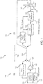
- Sensor control arrangement 100 may comprise a host controller 110, a power/data bus 120, and a remote sensor interface 130.
- Host controller 110 may comprise a data communication interface (also referred to herein as a first data communication interface) 122, an excitation signal synthesizer 124, and an amplifier 126.
- Remote sensor interface 130 may comprise an AC/DC power conditioner 132, a signal processor 134, and a data communication interface (also referred to herein as a second data communication interface) 136.
- Sensor control arrangement 100 may further comprise an electromagnetic sensor 140.
- remote sensor interface 130 may be located remotely from host controller 110.
- power/data bus 120 may comprise a length 102.
- length 102 may be at least two feet (.6096 m), and in various embodiments, length 102 may be up to 328 feet (100 m) or longer, for example. In this regard, it may be desirable to reduce the number of interconnects between remote sensor interface 130 and host controller 110 to reduce the weight and/or size of sensor control arrangement 100.
- power/data bus 120 may comprise a plurality of wires. In various embodiments, power/data bus 120 may comprise less than five wires.
- host controller 110 may be located at a first location 104 and remote sensor interface 130 may be located at a second location 106.
- First location 104 and second location 106 may be separated by a distance being less than or equal to length 102.
- excitation signal synthesizer 124 may generate an alternating current (AC) signal 125 via amplifier 126.
- Host controller 110 may send AC signal 125 to remote sensor interface 130.
- AC alternating current
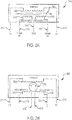
- electromagnetic sensor 140 may be similar to linear variable differential transformer (LVDT) 240 or rotary variable differential transformer (RVDT) 260.
- LVDT 240 may comprise a primary coil 242, a first secondary coil 244, a second secondary coil 246, and a ferromagnetic core 245.
- LVDT 240 may comprise two primary coil leads (i.e., first primary lead 251 and second primary lead 252).
- Primary coil 242 may be excited in response to an excitation signal (e.g., AC signal 250) received via first primary lead 251 and second primary lead 252.
- LVDT 240 may comprise three secondary coil leads (i.e., first secondary lead 253, second secondary lead 254, and third secondary lead 255).
- first primary lead 251, second primary lead 252, first secondary lead 253, second secondary lead 254, and third secondary lead 255 may comprise wires.
- RVDT 260 may comprise a primary coil 262, a first secondary coil 264, a second secondary coil 266, and a ferromagnetic core 265.
- RVDT 260 may comprise two primary coil leads (i.e., first primary lead 271 and second primary lead 272).
- Primary coil 262 may be excited in response to an excitation signal (e.g., AC signal 250) received via first primary lead 271 and second primary lead 272.
- RVDT 260 may comprise four secondary coil leads (i.e., first secondary lead 273, second secondary lead 274, third secondary lead 275, and fourth secondary lead 276).
- first primary lead 271, second primary lead 272, first secondary lead 273, second secondary lead 274, third secondary lead 275, and fourth secondary lead 276 may comprise wires.
- electromagnetic sensor 140 may comprise a plurality of secondary leads. Said secondary leads may be coupled between electromagnetic sensor 140 and signal processor 134. Signal processor 134 may be located in close proximity to electromagnetic sensor 140. For example, the distance between signal processor 134 and sensor 140 may be less than half of the length 102, and in various embodiments, less than a tenth of the length 102. In various embodiments, the distance between signal processor 134 and sensor 140 may be less than 3.28 feet (1 m). By placing signal processor 134 in close proximity to electromagnetic sensor 140, as opposed to placing signal processor 134 at location 104 for example, the weight of the plurality of leads extending between signal processor 134 and electromagnetic sensor 140 may be reduced. In this regard, electromagnetic sensor 140 may comprise at least three wires extending between electromagnetic sensor 140 and signal processor 134. In this regard, the number of wires of power/data bus 120 may be reduced.
- AC signal 125 may be received by electromagnetic sensor 140.
- Electromagnetic sensor 140 may sense the position of an adjacent component. Electromagnetic sensor 140 may output a sensor signal 142. Sensor signal 142 may comprise an analog signal. In this regard, sensor signal 142 may be referred to herein as an analog sensor signal. Sensor signal 142 may be received by signal processor 134. Signal processor 134 may process sensor signal 142 and generate a sensor signal (also referred to herein as a sensor feedback signal) 144. Sensor signal 144 may comprise a digital signal. In this regard, sensor signal 144 may be referred to herein as a digital sensor signal.
- Sensor signal 144 may comprise information regarding parameters of sensor signal 142 (e.g., magnitude, frequency, etc.) as well as position information. Sensor signal 144 may be sent to data communication interface 136 whereby it may be sent to data communication interface 122 via power/data bus 120. Excitation signal synthesizer 124 may receive sensor signal 144 via data communication interface 122 and may adjust one or more parameters (e.g., magnitude) of AC signal 125 based upon sensor signal 144. For example, excitation signal synthesizer 124 may determine that the amplitude of sensor signal 142 is below a threshold value and may increase the amplitude of AC signal 125 to increase the power received by electromagnetic sensor 140, which may in turn increase the amplitude of sensor signal 142.
- parameters of sensor signal 142 e.g., magnitude, frequency, etc.
- Excitation signal synthesizer 124 may receive sensor signal 144 via data communication interface 122 and may adjust one or more parameters (e.g., magnitude) of AC signal 125 based upon sensor signal 144. For example
- AC/DC power conditioner 132 may receive AC signal 125 via power/data bus 120.
- AC/DC power conditioner 132 may convert AC signal 125 into a DC power signal 138.
- Data communication interface 136 and/or signal processor 134 may be powered via DC power signal 138.
- DC power signal 138 may comprise, for example, between one and five volts.
- both data and power may be transmitted between host controller 110 and remote sensor interface 130.
- power/data bus 120 may direct AC signal 125 and sensor signal 144.
- the power and data signals i.e., AC signal 125 and sensor signal 144) may be transmitted through physically the same wires of power/data bus 120.
- the power bus and the data bus may be the same bus.
- Method 300 includes generating an AC signal (step 310).
- Method 300 includes sending the AC signal to a remote sensor interface (step 320).
- Method 300 includes sending the AC signal to the electromagnetic sensor (step 330).
- Method 300 includes powering the remote sensor interface via the AC signal (step 340).
- Method 300 includes powering the electromagnetic sensor via the AC signal (step 350).
- Method 300 includes receiving a sensor feedback signal from the remote sensor interface (step 360).
- Method 300 includes adjusting a parameter of the AC signal in response to the sensor feedback signal (step 370).
- step 310 may include generating, by host controller 110, AC signal 125.
- Step 320 may include sending, by host controller 110, AC signal 125 to remote sensor interface 130, via power/signal bus 120.
- Step 330 may include sending, by host controller 110, AC signal 125 to electromagnetic sensor 140, via power/signal bus 120.
- Step 340 may include powering, by host controller 110, remote sensor interface 130 via AC signal 125.
- Step 350 may include powering, by host controller 110, electromagnetic sensor 140 via AC signal 125.
- Step 360 may include receiving, by host controller 110, a sensor feedback signal (i.e., sensor signal 144) from remote sensor interface 130.
- Step 370 may include adjusting, by host controller 110, a parameter (e.g., amplitude) of AC signal 125, in response to the sensor feedback signal (i.e., sensor signal 144).
- a parameter e.g., amplitude
Landscapes
- Engineering & Computer Science (AREA)
- Physics & Mathematics (AREA)
- Power Engineering (AREA)
- Electromagnetism (AREA)
- General Physics & Mathematics (AREA)
- Fluid Mechanics (AREA)
- Computer Networks & Wireless Communication (AREA)
- Arrangements For Transmission Of Measured Signals (AREA)
Abstract
Description
- The disclosure generally relates to electrical sensing systems, and more particularly to the design of a sensor control system for remote sensors.
- Electromagnetic sensors typically use significant interconnect for sensor excitation and sensor information recovery. In some systems, to reduce the amount of interconnect from the sensor to other portions of the system, sensor excitation synthesis may be done remotely at the location of the sensor. However, the size and weight of the circuitry for exciting the sensor may be excessive, resulting in excessive circuitry at the remote location of the sensor.
- A sensor control arrangement is disclosed herein, in accordance with various embodiments. The sensor control arrangement may comprise a host controller, a remote sensor interface, a power/data bus extending between the host controller and the remote sensor interface, and an electromagnetic sensor. The electromagnetic sensor may be configured to receive an AC signal from the host controller via the power/data bus, and send a sensor signal to the remote sensor interface via the power/data bus.
- In various embodiments, the remote sensor interface may receive the AC signal. The host controller may comprise a first data communication interface, an excitation signal synthesizer in electronic communication with the first data communication interface, and an amplifier. The remote sensor interface may comprise an AC to DC power conditioner, a signal processor, and a second data communication interface. The AC to DC power conditioner may receive the AC signal and may convert the AC signal into a DC power signal. The signal processor and/or the second data communication interface may be powered by the DC power signal. At least three wires may extend between the sensor and the signal processor. The electromagnetic sensor may comprise a linear variable differential transformer. The electromagnetic sensor may comprise a rotary variable differential transformer. The power/data bus may comprise less than five wires.
- A sensor control arrangement is disclosed herein, in accordance with various embodiments. The sensor control arrangement may comprise a host controller located at a first location, a remote sensor interface located at a second location, wherein the second location is spaced apart from the first location by a distance, a power/data bus extending between the host controller and the remote sensor interface, and an electromagnetic sensor in electronic communication with the remote sensor interface, wherein the host controller is configured to send an alternating current (AC) signal to the remote sensor interface via the power/data bus, wherein the electromagnetic sensor is configured to receive the AC signal, and wherein the remote sensor interface is configured to receive an analog sensor signal from the electromagnetic sensor, convert the analog sensor signal to a digital sensor signal, and send the digital sensor signal to the host controller via the power/data bus.
- In various embodiments, the remote sensor interface may be configured to convert the AC signal to a direct current (DC) signal. The electromagnetic sensor may be in electronic communication with the remote sensor interface via at least three wires. The electromagnetic sensor may comprise a linear variable differential transformer (LVDT). The electromagnetic sensor may comprise a rotary variable differential transformer (RVDT). The distance may comprise at least two feet. The AC signal and the digital sensor signal may be sent via the same wires of the power/data bus.
- A method for exciting an electromagnetic sensor is disclosed herein, in accordance with various embodiments. The method may comprise generating, by a host controller, an alternating current (AC) signal, sending, by the host controller, the AC signal to a remote sensor interface, via a power/signal bus, sending, by the host controller, the AC signal to the electromagnetic sensor, via the power/signal bus, receiving, by the host controller, a sensor feedback signal from the remote sensor interface, and adjusting, by the host controller, a parameter of the AC signal, in response to the sensor feedback signal.
- In various embodiments, the method may further comprise powering, by the host controller, the remote sensor interface via the AC signal. The method may further comprise powering, by the host controller, the electromagnetic sensor via the AC signal.
- The foregoing features, elements, steps, or methods may be combined in various combinations without exclusivity, unless expressly indicated herein otherwise. These features, elements, steps, or methods as well as the operation of the disclosed embodiments will become more apparent in light of the following description and accompanying drawings.
- The subject matter of the present disclosure is particularly pointed out and distinctly claimed in the concluding portion of the specification. A more complete understanding of the present disclosure, however, may best be obtained by referring to the detailed description and claims when considered in connection with the drawing figures, wherein like numerals denote like elements.
-
FIG. 1 illustrates a schematic view of a sensor control arrangement, in accordance with various embodiments; -
FIG. 2A illustrates a schematic view of an electromagnetic sensor comprising a linear variable differential transformer (LVDT) having a plurality of wires extending therefrom, in accordance with various embodiments; -
FIG. 2B illustrates a schematic view of an electromagnetic sensor comprising a rotary variable differential transformer (RVDT) having a plurality of wires extending therefrom, in accordance with various embodiments; and -
FIG. 3 illustrates a method for exciting an electromagnetic sensor, in accordance with various embodiments. - The detailed description of various embodiments herein makes reference to the accompanying drawings, which show various embodiments by way of illustration. While these various embodiments are described in sufficient detail to enable those skilled in the art to practice the inventions, it should be understood that other embodiments may be realized and that logical, chemical and mechanical changes may be made without departing from the scope of the inventions. Thus, the detailed description herein is presented for purposes of illustration only and not of limitation. For example, the steps recited in any of the method or process descriptions may be executed in any order and are not necessarily limited to the order presented. Furthermore, any reference to singular includes plural embodiments, and any reference to more than one component or step may include a singular embodiment or step. Also, any reference to attached, fixed, connected or the like may include permanent, removable, temporary, partial, full and/or any other possible attachment option. Additionally, any reference to without contact (or similar phrases) may also include reduced contact or minimal contact.
- In the detailed description herein, references to "one embodiment", "an embodiment", "various embodiments", etc., indicate that the embodiment described may include a particular feature, structure, or characteristic, but every embodiment may not necessarily include the particular feature, structure, or characteristic. Moreover, such phrases are not necessarily referring to the same embodiment. Further, when a particular feature, structure, or characteristic is described in connection with an embodiment, it is submitted that it is within the knowledge of one skilled in the art to affect such feature, structure, or characteristic in connection with other embodiments whether or not explicitly described. After reading the description, it will be apparent to one skilled in the relevant art(s) how to implement the disclosure in alternative embodiments.
- As used herein, "electronic communication" means communication of electronic signals with physical coupling (e.g., "electrical communication" or "electrically coupled") or without physical coupling and via an electromagnetic field (e.g., "inductive communication" or "inductively coupled" or "inductive coupling"). In that regard, use of the term "electronic communication" includes both "electrical communication" and "inductive communication."
- With reference to
FIG. 1 , asensor control arrangement 100 is illustrated, in accordance with various embodiments.Sensor control arrangement 100 may comprise ahost controller 110, a power/data bus 120, and aremote sensor interface 130.Host controller 110 may comprise a data communication interface (also referred to herein as a first data communication interface) 122, anexcitation signal synthesizer 124, and anamplifier 126.Remote sensor interface 130 may comprise an AC/DC power conditioner 132, asignal processor 134, and a data communication interface (also referred to herein as a second data communication interface) 136.Sensor control arrangement 100 may further comprise anelectromagnetic sensor 140. - In various embodiments,
remote sensor interface 130 may be located remotely fromhost controller 110. In this regard, power/data bus 120 may comprise alength 102. In various embodiments,length 102 may be at least two feet (.6096 m), and in various embodiments,length 102 may be up to 328 feet (100 m) or longer, for example. In this regard, it may be desirable to reduce the number of interconnects betweenremote sensor interface 130 andhost controller 110 to reduce the weight and/or size ofsensor control arrangement 100. In various embodiments, power/data bus 120 may comprise a plurality of wires. In various embodiments, power/data bus 120 may comprise less than five wires. - In this regard,
host controller 110 may be located at afirst location 104 andremote sensor interface 130 may be located at asecond location 106.First location 104 andsecond location 106 may be separated by a distance being less than or equal tolength 102. - In various embodiments,
excitation signal synthesizer 124 may generate an alternating current (AC) signal 125 viaamplifier 126.Host controller 110 may send AC signal 125 toremote sensor interface 130. - With combined reference to
FIG. 1 ,FIG. 2A, and FIG. 2B ,electromagnetic sensor 140 may be similar to linear variable differential transformer (LVDT) 240 or rotary variable differential transformer (RVDT) 260.LVDT 240 may comprise aprimary coil 242, a firstsecondary coil 244, a secondsecondary coil 246, and aferromagnetic core 245.LVDT 240 may comprise two primary coil leads (i.e., firstprimary lead 251 and second primary lead 252).Primary coil 242 may be excited in response to an excitation signal (e.g., AC signal 250) received via firstprimary lead 251 and secondprimary lead 252.LVDT 240 may comprise three secondary coil leads (i.e., firstsecondary lead 253, second secondary lead 254, and third secondary lead 255). In various embodiments, firstprimary lead 251, secondprimary lead 252, firstsecondary lead 253, second secondary lead 254, and thirdsecondary lead 255 may comprise wires.RVDT 260 may comprise aprimary coil 262, a firstsecondary coil 264, a secondsecondary coil 266, and aferromagnetic core 265.RVDT 260 may comprise two primary coil leads (i.e., firstprimary lead 271 and second primary lead 272).Primary coil 262 may be excited in response to an excitation signal (e.g., AC signal 250) received via firstprimary lead 271 and secondprimary lead 272.RVDT 260 may comprise four secondary coil leads (i.e., firstsecondary lead 273, secondsecondary lead 274, thirdsecondary lead 275, and fourth secondary lead 276). In various embodiments, firstprimary lead 271, secondprimary lead 272, firstsecondary lead 273, secondsecondary lead 274, thirdsecondary lead 275, and fourthsecondary lead 276 may comprise wires. - In this regard,
electromagnetic sensor 140 may comprise a plurality of secondary leads. Said secondary leads may be coupled betweenelectromagnetic sensor 140 andsignal processor 134.Signal processor 134 may be located in close proximity toelectromagnetic sensor 140. For example, the distance betweensignal processor 134 andsensor 140 may be less than half of thelength 102, and in various embodiments, less than a tenth of thelength 102. In various embodiments, the distance betweensignal processor 134 andsensor 140 may be less than 3.28 feet (1 m). By placingsignal processor 134 in close proximity toelectromagnetic sensor 140, as opposed to placingsignal processor 134 atlocation 104 for example, the weight of the plurality of leads extending betweensignal processor 134 andelectromagnetic sensor 140 may be reduced. In this regard,electromagnetic sensor 140 may comprise at least three wires extending betweenelectromagnetic sensor 140 andsignal processor 134. In this regard, the number of wires of power/data bus 120 may be reduced. - In various embodiments, with reference to
FIG. 1 , AC signal 125 may be received byelectromagnetic sensor 140.Electromagnetic sensor 140 may sense the position of an adjacent component.Electromagnetic sensor 140 may output asensor signal 142.Sensor signal 142 may comprise an analog signal. In this regard,sensor signal 142 may be referred to herein as an analog sensor signal.Sensor signal 142 may be received bysignal processor 134.Signal processor 134 may processsensor signal 142 and generate a sensor signal (also referred to herein as a sensor feedback signal) 144.Sensor signal 144 may comprise a digital signal. In this regard,sensor signal 144 may be referred to herein as a digital sensor signal.Sensor signal 144 may comprise information regarding parameters of sensor signal 142 (e.g., magnitude, frequency, etc.) as well as position information.Sensor signal 144 may be sent todata communication interface 136 whereby it may be sent todata communication interface 122 via power/data bus 120.Excitation signal synthesizer 124 may receivesensor signal 144 viadata communication interface 122 and may adjust one or more parameters (e.g., magnitude) of AC signal 125 based uponsensor signal 144. For example,excitation signal synthesizer 124 may determine that the amplitude ofsensor signal 142 is below a threshold value and may increase the amplitude of AC signal 125 to increase the power received byelectromagnetic sensor 140, which may in turn increase the amplitude ofsensor signal 142. - In various embodiments, AC/
DC power conditioner 132 may receive AC signal 125 via power/data bus 120. AC/DC power conditioner 132 may convert AC signal 125 into aDC power signal 138.Data communication interface 136 and/orsignal processor 134 may be powered viaDC power signal 138.DC power signal 138 may comprise, for example, between one and five volts. In this regard, both data and power may be transmitted betweenhost controller 110 andremote sensor interface 130. In this regard, power/data bus 120 may directAC signal 125 andsensor signal 144. Stated differently, the power and data signals (i.e., AC signal 125 and sensor signal 144) may be transmitted through physically the same wires of power/data bus 120. In this regard, the power bus and the data bus may be the same bus. - With reference to
FIG. 3 , amethod 300 for exciting an electromagnetic sensor is provided, in accordance with various embodiments.Method 300 includes generating an AC signal (step 310).Method 300 includes sending the AC signal to a remote sensor interface (step 320).Method 300 includes sending the AC signal to the electromagnetic sensor (step 330).Method 300 includes powering the remote sensor interface via the AC signal (step 340).Method 300 includes powering the electromagnetic sensor via the AC signal (step 350).Method 300 includes receiving a sensor feedback signal from the remote sensor interface (step 360).Method 300 includes adjusting a parameter of the AC signal in response to the sensor feedback signal (step 370). - In various embodiments, with combined reference to
FIG. 1 andFIG. 3 , step 310 may include generating, byhost controller 110,AC signal 125. Step 320 may include sending, byhost controller 110, AC signal 125 toremote sensor interface 130, via power/signal bus 120. Step 330 may include sending, byhost controller 110, AC signal 125 toelectromagnetic sensor 140, via power/signal bus 120. Step 340 may include powering, byhost controller 110,remote sensor interface 130 viaAC signal 125. Step 350 may include powering, byhost controller 110,electromagnetic sensor 140 viaAC signal 125. Step 360 may include receiving, byhost controller 110, a sensor feedback signal (i.e., sensor signal 144) fromremote sensor interface 130. Step 370 may include adjusting, byhost controller 110, a parameter (e.g., amplitude) ofAC signal 125, in response to the sensor feedback signal (i.e., sensor signal 144). - Benefits, other advantages, and solutions to problems have been described herein with regard to specific embodiments. Furthermore, the connecting lines shown in the various figures contained herein are intended to represent various functional relationships and/or physical couplings between the various elements. It should be noted that many alternative or additional functional relationships or physical connections may be present in a practical system. However, the benefits, advantages, solutions to problems, and any elements that may cause any benefit, advantage, or solution to occur or become more pronounced are not to be construed as critical, required, or essential features or elements of the inventions. The scope of the inventions is accordingly to be limited by nothing other than the appended claims, in which reference to an element in the singular is not intended to mean "one and only one" unless explicitly so stated, but rather "one or more." Moreover, where a phrase similar to "at least one of A, B, or C" is used in the claims, it is intended that the phrase be interpreted to mean that A alone may be present in an embodiment, B alone may be present in an embodiment, C alone may be present in an embodiment, or that any combination of the elements A, B and C may be present in a single embodiment; for example, A and B, A and C, B and C, or A and B and C. Different cross-hatching is used throughout the figures to denote different parts but not necessarily to denote the same or different materials.
- Furthermore, no element, component, or method step in the present disclosure is intended to be dedicated to the public regardless of whether the element, component, or method step is explicitly recited in the claims. As used herein, the terms "comprises", "comprising", or any other variation thereof, are intended to cover a non-exclusive inclusion, such that a process, method, article, or apparatus that comprises a list of elements does not include only those elements but may include other elements not expressly listed or inherent to such process, method, article, or apparatus.
Claims (15)
- A sensor control arrangement (100) comprising:a host controller (110);a remote sensor interface (130);a power/data bus (120) extending between the host controller and the remote sensor interface; andan electromagnetic sensor (140) configured to:receive an AC signal from the host controller (110) via the power/data bus (120); andsend a sensor signal to the remote sensor interface (130) via the power/data bus (120).
- The sensor control arrangement of claim 1, wherein the remote sensor interface (130) receives the AC signal.
- The sensor control arrangement of claim 2, wherein the host controller (110) comprises:a first data communication interface (122);an excitation signal synthesizer (124) in electronic communication with the first data communication interface (122); andan amplifier (126).
- The sensor control arrangement of claim 3, wherein the remote sensor interface (130) comprises:an AC to DC power conditioner (132);a signal processor (134); anda second data communication interface (136).
- The sensor control arrangement of claim 4, wherein the AC to DC power conditioner (132) receives the AC signal and converts the AC signal into a DC power signal, and preferably wherein at least one of the signal processor (134) and the second data communication interface (136) is powered by the DC power signal.
- The sensor control arrangement of claim 4, wherein at least three wires extend between the sensor and the signal processor, and preferably wherein the electromagnetic sensor (140) comprises a linear variable differential transformer, and more preferably wherein the electromagnetic sensor (140) comprises a rotary variable differential transformer.
- The sensor control arrangement of any preceding claim, wherein the power/data bus (120) comprises less than five wires.
- A sensor control arrangement (100) comprising:a host controller (110) located at a first location;a remote sensor interface (130) located at a second location, wherein the second location is spaced apart from the first location by a distance;a power/data bus (120) extending between the host controller and the remote sensor interface; andan electromagnetic sensor (140) in electronic communication with the remote sensor interface;wherein the host controller (110) is configured to send an alternating current (AC) signal to the remote sensor interface (130) via the power/data bus (120),wherein the electromagnetic sensor (140) is configured to receive the AC signal; andwherein the remote sensor interface (130) is configured to:receive an analog sensor signal from the electromagnetic sensor (140);convert the analog sensor signal to a digital sensor signal; andsend the digital sensor signal to the host controller (110) via the power/data bus (120).
- The sensor control arrangement of claim 8, wherein the remote sensor interface (130) is configured to convert the AC signal to a direct current (DC) signal.
- The sensor control arrangement of claims 8 or 9, wherein the electromagnetic sensor (140) is in electronic communication with the remote sensor interface (130) via at least three wires.
- The sensor control arrangement of claim 10, wherein the electromagnetic sensor (140) comprises a linear variable differential transformer (LVDT); or
wherein the electromagnetic sensor (140) comprises a rotary variable differential transformer (RVDT). - The sensor control arrangement of any of claims 8-11, wherein the distance comprises at least two feet.
- The sensor control arrangement of any of claims 8-12, wherein the AC signal and the digital sensor signal are sent via the same wires of the power/data bus.
- A method for exciting an electromagnetic sensor, comprising:generating, by a host controller (110), an alternating current (AC) signal;sending, by the host controller (110), the AC signal to a remote sensor interface, via a power/signal bus;sending, by the host controller (110), the AC signal to the electromagnetic sensor, via the power/signal bus;receiving, by the host controller (110), a sensor feedback signal from the remote sensor interface; andadjusting, by the host controller (110), a parameter of the AC signal, in response to the sensor feedback signal.
- The method of claim 14, further comprising:powering, by the host controller (110), the remote sensor interface via the AC signal; orpowering, by the host controller (110), the electromagnetic sensor via the AC signal.
Applications Claiming Priority (1)
| Application Number | Priority Date | Filing Date | Title |
|---|---|---|---|
| US15/614,293 US10557879B2 (en) | 2017-06-05 | 2017-06-05 | Sensor excitation in systems where remote sensor signal processing is performed |
Publications (2)
| Publication Number | Publication Date |
|---|---|
| EP3413579A1 true EP3413579A1 (en) | 2018-12-12 |
| EP3413579B1 EP3413579B1 (en) | 2021-09-15 |
Family
ID=62684577
Family Applications (1)
| Application Number | Title | Priority Date | Filing Date |
|---|---|---|---|
| EP18175506.7A Active EP3413579B1 (en) | 2017-06-05 | 2018-06-01 | Sensor excitation in systems where remote sensor signal processing is performed |
Country Status (2)
| Country | Link |
|---|---|
| US (1) | US10557879B2 (en) |
| EP (1) | EP3413579B1 (en) |
Citations (3)
| Publication number | Priority date | Publication date | Assignee | Title |
|---|---|---|---|---|
| US20050021712A1 (en) * | 2003-01-24 | 2005-01-27 | Constantin Chassapis | Multi-user, multi-device remote access system |
| CN202372137U (en) * | 2011-12-12 | 2012-08-08 | 西安瑞日电子发展有限公司 | Angle sensor demodulation structure on basis of coherent demodulation technology |
| CN205508098U (en) * | 2015-12-04 | 2016-08-24 | 中国航空工业第六一八研究所 | Low -power consumption wireless sensing demodulator for linear displacement sensor |
Family Cites Families (5)
| Publication number | Priority date | Publication date | Assignee | Title |
|---|---|---|---|---|
| US5515041A (en) | 1993-06-14 | 1996-05-07 | Simmonds Precision Products Inc. | Composite shaft monitoring system |
| US5764927A (en) * | 1995-09-29 | 1998-06-09 | Allen Bradley Company, Inc. | Backplane data transfer technique for industrial automation controllers |
| US9389260B2 (en) | 2012-09-28 | 2016-07-12 | General Electric Company | Systems and methods for monitoring sensors |
| CA2834350C (en) | 2011-04-25 | 2019-06-25 | Endotronix, Inc. | Wireless sensor reader |
| US10067170B2 (en) * | 2011-12-28 | 2018-09-04 | United Safety, Inc. | Power line proximity sensing and warning system |
-
2017
- 2017-06-05 US US15/614,293 patent/US10557879B2/en active Active
-
2018
- 2018-06-01 EP EP18175506.7A patent/EP3413579B1/en active Active
Patent Citations (3)
| Publication number | Priority date | Publication date | Assignee | Title |
|---|---|---|---|---|
| US20050021712A1 (en) * | 2003-01-24 | 2005-01-27 | Constantin Chassapis | Multi-user, multi-device remote access system |
| CN202372137U (en) * | 2011-12-12 | 2012-08-08 | 西安瑞日电子发展有限公司 | Angle sensor demodulation structure on basis of coherent demodulation technology |
| CN205508098U (en) * | 2015-12-04 | 2016-08-24 | 中国航空工业第六一八研究所 | Low -power consumption wireless sensing demodulator for linear displacement sensor |
Also Published As
| Publication number | Publication date |
|---|---|
| US10557879B2 (en) | 2020-02-11 |
| EP3413579B1 (en) | 2021-09-15 |
| US20180348275A1 (en) | 2018-12-06 |
Similar Documents
| Publication | Publication Date | Title |
|---|---|---|
| US8575944B2 (en) | Foreign object detection in inductive coupled devices | |
| US7705741B2 (en) | Detection of a broken wire between power sourcing equipment and a powered device | |
| CN108462260B (en) | Detector, power transmitter and receiver, and power supply system | |
| CN107408833B (en) | Inductive power transmitter | |
| WO2021141925A1 (en) | Systems and methods for wireless power transfer including pulse width encoded data communications | |
| KR102088073B1 (en) | Transmission of signals through a non-contact interface | |
| JP6977654B2 (en) | Wireless power receiving device and wireless power transmission system | |
| CN110495072B (en) | Wireless charging device and method for detecting receiver device | |
| US20210215845A1 (en) | Foreign Object Detector, Wireless Power Transmission System Comprising a Foreign Object Detector and Method of Detecting a Foreign Object | |
| WO2013016382A2 (en) | System for measuring current and method of making same | |
| CN103575957A (en) | High efficiency energy harvester and methods thereof | |
| JP2019162023A (en) | Wireless power transmission device and power receiving side current detection circuit thereof | |
| US10466314B2 (en) | Integrated current sensor | |
| US20230087951A1 (en) | Automatic Gain Control For Communications Demodulation In Wireless Power Transfer Systems | |
| WO2016134950A1 (en) | Monitoring multiple subsea electric motors | |
| CN111505527A (en) | System and Method for Ground Fault Detection Using Hall Effect Sensors | |
| EP3413579B1 (en) | Sensor excitation in systems where remote sensor signal processing is performed | |
| TW201044424A (en) | Electromagnetic apparatus using shared flux in a multi-load parallel magnetic circuit and method of operation | |
| CN109541702B (en) | A large depth MRS transmitting and receiving system and detection method | |
| CN104412485B (en) | Object recognition for energy transfer systems | |
| JP6842885B2 (en) | Wireless power supply device and wireless power supply method | |
| CN104471413B (en) | Method and device for locating a current sensor | |
| JP6394123B2 (en) | Coil unit | |
| US20230134561A1 (en) | Multi-Coil Polygonal Wireless Power Receiver Antenna | |
| CN110277836B (en) | Wireless power transmitter and wireless power transfer system |
Legal Events
| Date | Code | Title | Description |
|---|---|---|---|
| PUAI | Public reference made under article 153(3) epc to a published international application that has entered the european phase |
Free format text: ORIGINAL CODE: 0009012 |
|
| STAA | Information on the status of an ep patent application or granted ep patent |
Free format text: STATUS: THE APPLICATION HAS BEEN PUBLISHED |
|
| AK | Designated contracting states |
Kind code of ref document: A1 Designated state(s): AL AT BE BG CH CY CZ DE DK EE ES FI FR GB GR HR HU IE IS IT LI LT LU LV MC MK MT NL NO PL PT RO RS SE SI SK SM TR |
|
| AX | Request for extension of the european patent |
Extension state: BA ME |
|
| STAA | Information on the status of an ep patent application or granted ep patent |
Free format text: STATUS: REQUEST FOR EXAMINATION WAS MADE |
|
| 17P | Request for examination filed |
Effective date: 20190610 |
|
| RBV | Designated contracting states (corrected) |
Designated state(s): AL AT BE BG CH CY CZ DE DK EE ES FI FR GB GR HR HU IE IS IT LI LT LU LV MC MK MT NL NO PL PT RO RS SE SI SK SM TR |
|
| STAA | Information on the status of an ep patent application or granted ep patent |
Free format text: STATUS: EXAMINATION IS IN PROGRESS |
|
| 17Q | First examination report despatched |
Effective date: 20200526 |
|
| GRAP | Despatch of communication of intention to grant a patent |
Free format text: ORIGINAL CODE: EPIDOSNIGR1 |
|
| STAA | Information on the status of an ep patent application or granted ep patent |
Free format text: STATUS: GRANT OF PATENT IS INTENDED |
|
| INTG | Intention to grant announced |
Effective date: 20210416 |
|
| GRAS | Grant fee paid |
Free format text: ORIGINAL CODE: EPIDOSNIGR3 |
|
| GRAA | (expected) grant |
Free format text: ORIGINAL CODE: 0009210 |
|
| STAA | Information on the status of an ep patent application or granted ep patent |
Free format text: STATUS: THE PATENT HAS BEEN GRANTED |
|
| AK | Designated contracting states |
Kind code of ref document: B1 Designated state(s): AL AT BE BG CH CY CZ DE DK EE ES FI FR GB GR HR HU IE IS IT LI LT LU LV MC MK MT NL NO PL PT RO RS SE SI SK SM TR |
|
| REG | Reference to a national code |
Ref country code: CH Ref legal event code: EP |
|
| REG | Reference to a national code |
Ref country code: DE Ref legal event code: R096 Ref document number: 602018023491 Country of ref document: DE |
|
| REG | Reference to a national code |
Ref country code: IE Ref legal event code: FG4D |
|
| REG | Reference to a national code |
Ref country code: AT Ref legal event code: REF Ref document number: 1431467 Country of ref document: AT Kind code of ref document: T Effective date: 20211015 |
|
| REG | Reference to a national code |
Ref country code: LT Ref legal event code: MG9D |
|
| REG | Reference to a national code |
Ref country code: NL Ref legal event code: MP Effective date: 20210915 |
|
| PG25 | Lapsed in a contracting state [announced via postgrant information from national office to epo] |
Ref country code: NO Free format text: LAPSE BECAUSE OF FAILURE TO SUBMIT A TRANSLATION OF THE DESCRIPTION OR TO PAY THE FEE WITHIN THE PRESCRIBED TIME-LIMIT Effective date: 20211215 Ref country code: LT Free format text: LAPSE BECAUSE OF FAILURE TO SUBMIT A TRANSLATION OF THE DESCRIPTION OR TO PAY THE FEE WITHIN THE PRESCRIBED TIME-LIMIT Effective date: 20210915 Ref country code: BG Free format text: LAPSE BECAUSE OF FAILURE TO SUBMIT A TRANSLATION OF THE DESCRIPTION OR TO PAY THE FEE WITHIN THE PRESCRIBED TIME-LIMIT Effective date: 20211215 Ref country code: HR Free format text: LAPSE BECAUSE OF FAILURE TO SUBMIT A TRANSLATION OF THE DESCRIPTION OR TO PAY THE FEE WITHIN THE PRESCRIBED TIME-LIMIT Effective date: 20210915 Ref country code: FI Free format text: LAPSE BECAUSE OF FAILURE TO SUBMIT A TRANSLATION OF THE DESCRIPTION OR TO PAY THE FEE WITHIN THE PRESCRIBED TIME-LIMIT Effective date: 20210915 Ref country code: RS Free format text: LAPSE BECAUSE OF FAILURE TO SUBMIT A TRANSLATION OF THE DESCRIPTION OR TO PAY THE FEE WITHIN THE PRESCRIBED TIME-LIMIT Effective date: 20210915 Ref country code: SE Free format text: LAPSE BECAUSE OF FAILURE TO SUBMIT A TRANSLATION OF THE DESCRIPTION OR TO PAY THE FEE WITHIN THE PRESCRIBED TIME-LIMIT Effective date: 20210915 |
|
| REG | Reference to a national code |
Ref country code: AT Ref legal event code: MK05 Ref document number: 1431467 Country of ref document: AT Kind code of ref document: T Effective date: 20210915 |
|
| PG25 | Lapsed in a contracting state [announced via postgrant information from national office to epo] |
Ref country code: LV Free format text: LAPSE BECAUSE OF FAILURE TO SUBMIT A TRANSLATION OF THE DESCRIPTION OR TO PAY THE FEE WITHIN THE PRESCRIBED TIME-LIMIT Effective date: 20210915 Ref country code: GR Free format text: LAPSE BECAUSE OF FAILURE TO SUBMIT A TRANSLATION OF THE DESCRIPTION OR TO PAY THE FEE WITHIN THE PRESCRIBED TIME-LIMIT Effective date: 20211216 |
|
| PG25 | Lapsed in a contracting state [announced via postgrant information from national office to epo] |
Ref country code: AT Free format text: LAPSE BECAUSE OF FAILURE TO SUBMIT A TRANSLATION OF THE DESCRIPTION OR TO PAY THE FEE WITHIN THE PRESCRIBED TIME-LIMIT Effective date: 20210915 |
|
| PG25 | Lapsed in a contracting state [announced via postgrant information from national office to epo] |
Ref country code: IS Free format text: LAPSE BECAUSE OF FAILURE TO SUBMIT A TRANSLATION OF THE DESCRIPTION OR TO PAY THE FEE WITHIN THE PRESCRIBED TIME-LIMIT Effective date: 20220115 Ref country code: SM Free format text: LAPSE BECAUSE OF FAILURE TO SUBMIT A TRANSLATION OF THE DESCRIPTION OR TO PAY THE FEE WITHIN THE PRESCRIBED TIME-LIMIT Effective date: 20210915 Ref country code: SK Free format text: LAPSE BECAUSE OF FAILURE TO SUBMIT A TRANSLATION OF THE DESCRIPTION OR TO PAY THE FEE WITHIN THE PRESCRIBED TIME-LIMIT Effective date: 20210915 Ref country code: RO Free format text: LAPSE BECAUSE OF FAILURE TO SUBMIT A TRANSLATION OF THE DESCRIPTION OR TO PAY THE FEE WITHIN THE PRESCRIBED TIME-LIMIT Effective date: 20210915 Ref country code: PT Free format text: LAPSE BECAUSE OF FAILURE TO SUBMIT A TRANSLATION OF THE DESCRIPTION OR TO PAY THE FEE WITHIN THE PRESCRIBED TIME-LIMIT Effective date: 20220117 Ref country code: PL Free format text: LAPSE BECAUSE OF FAILURE TO SUBMIT A TRANSLATION OF THE DESCRIPTION OR TO PAY THE FEE WITHIN THE PRESCRIBED TIME-LIMIT Effective date: 20210915 Ref country code: NL Free format text: LAPSE BECAUSE OF FAILURE TO SUBMIT A TRANSLATION OF THE DESCRIPTION OR TO PAY THE FEE WITHIN THE PRESCRIBED TIME-LIMIT Effective date: 20210915 Ref country code: ES Free format text: LAPSE BECAUSE OF FAILURE TO SUBMIT A TRANSLATION OF THE DESCRIPTION OR TO PAY THE FEE WITHIN THE PRESCRIBED TIME-LIMIT Effective date: 20210915 Ref country code: EE Free format text: LAPSE BECAUSE OF FAILURE TO SUBMIT A TRANSLATION OF THE DESCRIPTION OR TO PAY THE FEE WITHIN THE PRESCRIBED TIME-LIMIT Effective date: 20210915 Ref country code: CZ Free format text: LAPSE BECAUSE OF FAILURE TO SUBMIT A TRANSLATION OF THE DESCRIPTION OR TO PAY THE FEE WITHIN THE PRESCRIBED TIME-LIMIT Effective date: 20210915 Ref country code: AL Free format text: LAPSE BECAUSE OF FAILURE TO SUBMIT A TRANSLATION OF THE DESCRIPTION OR TO PAY THE FEE WITHIN THE PRESCRIBED TIME-LIMIT Effective date: 20210915 |
|
| REG | Reference to a national code |
Ref country code: DE Ref legal event code: R097 Ref document number: 602018023491 Country of ref document: DE |
|
| PLBE | No opposition filed within time limit |
Free format text: ORIGINAL CODE: 0009261 |
|
| STAA | Information on the status of an ep patent application or granted ep patent |
Free format text: STATUS: NO OPPOSITION FILED WITHIN TIME LIMIT |
|
| PG25 | Lapsed in a contracting state [announced via postgrant information from national office to epo] |
Ref country code: DK Free format text: LAPSE BECAUSE OF FAILURE TO SUBMIT A TRANSLATION OF THE DESCRIPTION OR TO PAY THE FEE WITHIN THE PRESCRIBED TIME-LIMIT Effective date: 20210915 |
|
| 26N | No opposition filed |
Effective date: 20220616 |
|
| PG25 | Lapsed in a contracting state [announced via postgrant information from national office to epo] |
Ref country code: SI Free format text: LAPSE BECAUSE OF FAILURE TO SUBMIT A TRANSLATION OF THE DESCRIPTION OR TO PAY THE FEE WITHIN THE PRESCRIBED TIME-LIMIT Effective date: 20210915 |
|
| PG25 | Lapsed in a contracting state [announced via postgrant information from national office to epo] |
Ref country code: MC Free format text: LAPSE BECAUSE OF FAILURE TO SUBMIT A TRANSLATION OF THE DESCRIPTION OR TO PAY THE FEE WITHIN THE PRESCRIBED TIME-LIMIT Effective date: 20210915 Ref country code: IT Free format text: LAPSE BECAUSE OF FAILURE TO SUBMIT A TRANSLATION OF THE DESCRIPTION OR TO PAY THE FEE WITHIN THE PRESCRIBED TIME-LIMIT Effective date: 20210915 |
|
| REG | Reference to a national code |
Ref country code: CH Ref legal event code: PL |
|
| REG | Reference to a national code |
Ref country code: BE Ref legal event code: MM Effective date: 20220630 |
|
| PG25 | Lapsed in a contracting state [announced via postgrant information from national office to epo] |
Ref country code: LU Free format text: LAPSE BECAUSE OF NON-PAYMENT OF DUE FEES Effective date: 20220601 Ref country code: LI Free format text: LAPSE BECAUSE OF NON-PAYMENT OF DUE FEES Effective date: 20220630 Ref country code: IE Free format text: LAPSE BECAUSE OF NON-PAYMENT OF DUE FEES Effective date: 20220601 Ref country code: CH Free format text: LAPSE BECAUSE OF NON-PAYMENT OF DUE FEES Effective date: 20220630 |
|
| PG25 | Lapsed in a contracting state [announced via postgrant information from national office to epo] |
Ref country code: BE Free format text: LAPSE BECAUSE OF NON-PAYMENT OF DUE FEES Effective date: 20220630 |
|
| P01 | Opt-out of the competence of the unified patent court (upc) registered |
Effective date: 20230522 |
|
| PG25 | Lapsed in a contracting state [announced via postgrant information from national office to epo] |
Ref country code: HU Free format text: LAPSE BECAUSE OF FAILURE TO SUBMIT A TRANSLATION OF THE DESCRIPTION OR TO PAY THE FEE WITHIN THE PRESCRIBED TIME-LIMIT; INVALID AB INITIO Effective date: 20180601 |
|
| PG25 | Lapsed in a contracting state [announced via postgrant information from national office to epo] |
Ref country code: MK Free format text: LAPSE BECAUSE OF FAILURE TO SUBMIT A TRANSLATION OF THE DESCRIPTION OR TO PAY THE FEE WITHIN THE PRESCRIBED TIME-LIMIT Effective date: 20210915 Ref country code: CY Free format text: LAPSE BECAUSE OF FAILURE TO SUBMIT A TRANSLATION OF THE DESCRIPTION OR TO PAY THE FEE WITHIN THE PRESCRIBED TIME-LIMIT Effective date: 20210915 |
|
| PG25 | Lapsed in a contracting state [announced via postgrant information from national office to epo] |
Ref country code: MT Free format text: LAPSE BECAUSE OF FAILURE TO SUBMIT A TRANSLATION OF THE DESCRIPTION OR TO PAY THE FEE WITHIN THE PRESCRIBED TIME-LIMIT Effective date: 20210915 |
|
| PGFP | Annual fee paid to national office [announced via postgrant information from national office to epo] |
Ref country code: DE Payment date: 20250520 Year of fee payment: 8 |
|
| PGFP | Annual fee paid to national office [announced via postgrant information from national office to epo] |
Ref country code: GB Payment date: 20250520 Year of fee payment: 8 |
|
| PGFP | Annual fee paid to national office [announced via postgrant information from national office to epo] |
Ref country code: FR Payment date: 20250521 Year of fee payment: 8 |
|
| PG25 | Lapsed in a contracting state [announced via postgrant information from national office to epo] |
Ref country code: TR Free format text: LAPSE BECAUSE OF FAILURE TO SUBMIT A TRANSLATION OF THE DESCRIPTION OR TO PAY THE FEE WITHIN THE PRESCRIBED TIME-LIMIT Effective date: 20210915 |