JP6842885B2 - Wireless power supply device and wireless power supply method - Google Patents
Wireless power supply device and wireless power supply method Download PDFInfo
- Publication number
- JP6842885B2 JP6842885B2 JP2016220775A JP2016220775A JP6842885B2 JP 6842885 B2 JP6842885 B2 JP 6842885B2 JP 2016220775 A JP2016220775 A JP 2016220775A JP 2016220775 A JP2016220775 A JP 2016220775A JP 6842885 B2 JP6842885 B2 JP 6842885B2
- Authority
- JP
- Japan
- Prior art keywords
- power
- transmission side
- coil
- power transmission
- power receiving
- Prior art date
- Legal status (The legal status is an assumption and is not a legal conclusion. Google has not performed a legal analysis and makes no representation as to the accuracy of the status listed.)
- Active
Links
Images


Landscapes
- Charge And Discharge Circuits For Batteries Or The Like (AREA)
Description
本発明は、無線給電装置、及び無線給電方法に関する。 The present invention relates to a wireless power feeding device and a wireless power feeding method.
送電装置から受電装置へと、電磁誘導や磁界共鳴等を利用して、電力を伝送する無線給電装置が知られている。 A wireless power feeding device that transmits electric power from a power transmitting device to a power receiving device by using electromagnetic induction, magnetic field resonance, or the like is known.
例えば、非特許文献1には、送電側コイルと受電側コイルとを共振させて、電力を伝送することで、電送効率と電送距離を向上させた非接触給電方法が開示されている。 For example, Non-Patent Document 1 discloses a non-contact power feeding method in which a power transmitting side coil and a power receiving side coil are resonated to transmit electric power to improve transmission efficiency and transmission distance.
また、例えば、特許文献1には、電力伝送用コイルを包含部で覆い、該コイルを、送電部インピーダンスと、受電部インピーダンスと、良導体媒質のインピーダンスとで定まる周波数で共振させた電力伝送装置が開示されている。 Further, for example, Patent Document 1 describes a power transmission device in which a power transmission coil is covered with an inclusion portion, and the coil is resonated at a frequency determined by the impedance of the power transmission unit, the impedance of the power reception unit, and the impedance of a good conductor medium. It is disclosed.
また、例えば、特許文献2には、制御部が、送電部から受電部への送電状況に基づいて、送電部に対する受電部の位置ずれを検出する前に、送電部が、通信部を介して、受電部から受信した負荷情報に基づいて、インピーダンスを調整する電力伝送システムが開示されている。
Further, for example, in
無線給電装置が、例えば、空気中から水中へと移動すると、送電装置又は受電装置における共振周波数やインピーダンスが変化するため、伝送効率が低下するという問題がある。 When the wireless power feeding device moves from the air to the water, for example, the resonance frequency and impedance of the power transmitting device or the power receiving device change, so that there is a problem that the transmission efficiency is lowered.
非特許文献1及び特許文献1に記載の電力伝送装置には、装置周辺の媒質変化に伴って、インピーダンスを調整する機構が備わっていないため、装置周辺の媒質が変化すると伝送効率が低下してしまう。また、特許文献2に記載の電力伝送システムは、送電部と受電部との間での通信を利用して、インピーダンスを調整するため、媒質の種類によっては、通信が途絶し、伝送効率が低下してしまう。
Since the power transmission devices described in Non-Patent Document 1 and Patent Document 1 do not have a mechanism for adjusting impedance according to changes in the medium around the device, transmission efficiency decreases when the medium around the device changes. It ends up. Further, since the power transmission system described in
本発明は、上記した課題を解決するためになされたものであり、周辺の媒質が変化しても、高効率な給電が可能な無線給電装置を提供することを課題とする。 The present invention has been made to solve the above-mentioned problems, and an object of the present invention is to provide a wireless power feeding device capable of highly efficient power feeding even if the surrounding medium changes.
前記課題を解決するために、本発明は、送電装置から受電装置へと非接触で電力を伝送する無線給電装置であって、前記送電装置は、電源部から交流電流を供給されて、磁束を発生する送電側コイルと、前記電源部から出力される交流電流の周波数と、前記送電側コイルの共振周波数とを整合する送電側整合回路と、前記送電側コイルの周辺の媒質を判定する送電側媒質判定部と、該送電側媒質判定部の判定に基づいて、複数の前記送電側整合回路の中から、前記電源部と接続する所定の送電側整合回路へと切り替える送電側切替部と、を備え、前記受電装置は、前記磁束と鎖交して、負荷へと誘導電流を供給する受電側コイルと、前記電源部から出力される交流電流の周波数と、前記受電側コイルの共振周波数とを整合する受電側整合回路と、前記受電側コイルの周辺の媒質を判定する受電側媒質判定部と、該受電側媒質判定部の判定に基づいて、複数の前記受電側整合回路の中から、前記負荷と接続する所定の受電側整合回路へと切り替える受電側切替部と、を備えることを特徴とする。 In order to solve the above problems, the present invention is a wireless power feeding device that transmits electric power from a power transmitting device to a power receiving device in a non-contact manner, and the power transmitting device is supplied with an alternating current from a power supply unit to generate magnetic flux. A power transmission side matching circuit that matches the generated power transmission side coil, the frequency of the alternating current output from the power supply unit, and the resonance frequency of the power transmission side coil, and the power transmission side that determines the medium around the power transmission side coil. A medium determination unit and a transmission side switching unit that switches from a plurality of the transmission side matching circuits to a predetermined transmission side matching circuit connected to the power supply unit based on the determination of the transmission side medium determination unit. The power receiving device includes a power receiving coil that interlinks with the magnetic flux to supply an induced current to the load, an alternating current frequency output from the power supply unit, and a resonance frequency of the power receiving coil. Based on the determination of the power receiving side matching circuit that matches, the power receiving side medium determination unit that determines the medium around the power receiving side coil, and the determination of the power receiving side medium determination unit, the power receiving side matching circuit is selected from among the plurality of power receiving side matching circuits. It is characterized by including a power receiving side switching unit for switching to a predetermined power receiving side matching circuit connected to the load.
本発明によれば、周辺の媒質が変化しても、高効率な給電が可能な無線給電装置を提供することができる。 According to the present invention, it is possible to provide a wireless power feeding device capable of highly efficient power feeding even if the surrounding medium changes.
≪第1実施形態≫
〔無線給電装置の全体構成〕
まず、図1を参照して、本発明の第1実施形態に係る無線給電装置100の構成について説明する。
<< First Embodiment >>
[Overall configuration of wireless power supply device]
First, the configuration of the wireless
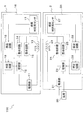
図1に示すように、無線給電装置100は、送電装置1と、受電装置2と、を備える。無線給電装置100において、送電装置1から受電装置2へと、非接触で電力が伝送され、受電装置2から負荷30(例えば、二次電池、電動駆動装置、等)へと、電力が供給される。
As shown in FIG. 1, the wireless
送電装置1に設けられる送電側コイルに、交流電流が流れると、送電側コイルに磁束が発生する。該磁束が、受電装置2に設けられる受電側コイルと鎖交することにより、受電側コイルに、誘導電流が流れる。即ち、無線給電装置100は、電磁誘導を利用して、送電装置1から受電装置2へと電力を伝送する。電力伝送に寄与する磁束が多い程(送電側コイルと受電側コイルとの結合が強い程)、伝送効率は高くなる。
When an alternating current flows through the power transmission side coil provided in the power transmission device 1, magnetic flux is generated in the power transmission side coil. When the magnetic flux interlinks with the power receiving side coil provided in the
〔送電装置の構成〕
図1に示すように、送電装置1は、電源部11、切替部(送電側切替部)12、送電側コイル13、整合回路(送電側整合回路)14、整合回路(送電側整合回路)15、媒質判定部(送電側媒質判定部)16、を備える。媒質判定部16は、媒質判定用センサ17、検出回路18、判定回路19、を備える。本実施形態では、電源部11、切替部12、送電側コイル13、整合回路14、整合回路15、媒質判定部16、検出回路18、判定回路19は、送電装置1の筐体内に設けられる。また、媒質判定用センサ17は、送電装置1の筐体外に設けられる。
[Structure of power transmission device]
As shown in FIG. 1, the power transmission device 1 includes a
電源部11は、切替部12、送電側コイル13と接続される。電源部11は、商用電源等の外部電源を、別の周波数の交流電流に変換し、送電側コイル13へと供給する。
The
送電側コイル13は、電源部11、整合回路14及び整合回路15と接続される。送電側コイル13は、周辺の媒質に依存せずに、使用できるようにするため、ハウジングや筐体に収容される。送電側コイル13は、電源部11から交流電流が供給されることで、磁束を発生する。
The power
整合回路14,15は、切替部12、送電側コイル13と接続される。送電装置1には、少なくとも2つ以上の整合回路が設けられる。整合回路14,15は、電源部11から出力される交流電流の周波数と、送電側コイル13の共振周波数とを整合する。整合回路14,15は、例えば、コンデンサ、等で構成することができる。
The
整合回路14がコンデンサで構成される場合、コンデンサの静電容量は、空気中における送電側コイル13の共振周波数が、電源部11から出力される交流電流の周波数と一致するように、設定される。また、整合回路15がコンデンサで構成される場合、コンデンサの静電容量は、水中における送電側コイル13の共振周波数が、電源部11から出力される交流電流の周波数と一致するように、設定される。電源部11から出力される交流電流の周波数と、送電側コイル13の共振周波数とを、一致させることで、高効率な送電が可能になる。
When the matching
切替部12は、電源部11、整合回路14または整合回路15と接続される。切替部12は、判定回路19から入力される判定結果に基づいて、複数の整合回路(例えば、整合回路14,15)の中から、電源部11と接続する整合回路を選択して切り替える。
The
例えば、判定回路19により、送電側コイル13の周辺の媒質が空気であると判定された場合、切替部12は、整合回路14を選択し、電源部11と整合回路14とを接続する。この場合、電源部11から出力される交流電流の周波数と、空気中における送電側コイル13の共振周波数とは、一致する。なお、既に切替部12と整合回路14とが接続されているときは、切替部12は、その接続状態を維持するものとする。
For example, when the
また、例えば、判定回路19により、送電側コイル13の周辺媒質が水であると判定された場合、切替部12は、整合回路15を選択し、電源部11と整合回路15とを接続する。この場合、電源部11から出力される交流電流の周波数と、水中における送電側コイル13の共振周波数とは、一致する。なお、既に切替部12と整合回路15とが接続されているときは、切替部12は、その接続状態を維持するものとする。この点は、以下の説明において、同様である。
Further, for example, when the
媒質判定部16は、送電側コイル13の周辺の媒質を検出し、該媒質が、水であるか空気であるかを判定する。
The
なお、本実施形態では、媒質判定部16が判定する媒質として、空気と水を一例に挙げて説明するが、媒質判定部16が判定する媒質は、これに限定されるものではない。媒質判定部16が判定する媒質は、例えば、純水、海水、オイル、アルコール、有機溶剤、等であっても良い。
In the present embodiment, air and water will be described as an example of the medium determined by the
媒質判定用センサ17は、検出回路18と接続され、送電側コイル13の周辺に設けられる。媒質判定用センサ17は、検出回路18により駆動され、送電側コイル13の周辺の媒質の特性を検出し、検出結果を検出回路18へと出力する。媒質の特性としては、例えば、導電率、音速、音響インピーダンス、密度、浮力、誘電率、粘度、屈折率、等が挙げられる。なお、媒質判定用センサ17は、媒質から離隔されて、送電側コイル13と共に、ハウジングや筐体に収容されていても良い。
The
検出回路18は、媒質判定用センサ17、判定回路19と接続される。検出回路18は、媒質判定用センサ17から入力される検出結果に基づいて、媒質の特性を測定し、測定結果を判定回路19へと出力する。
The
判定回路19は、切替部12、検出回路18と接続される。判定回路19は、検出回路18から入力される測定結果に基づいて、送電側コイル13の周辺の媒質が、水であるか空気であるかを判定し、判定結果を切替部12へと出力する。
The
なお、本実施形態では、媒質判定部16として、媒質判定用センサ17、検出回路18、判定回路19、を備えた構成を、一例に挙げて説明するが、媒質判定部16の構成は、特に、限定されるものではない。例えば、媒質判定部16の構成として、検出回路18や判定回路19を設けずに、フロートとスイッチを組み合わせた構成とすることもできる。この場合、媒質判定部16は、各媒質における浮力の違いを利用して、送電側コイル13の周辺の媒質が、水であるか空気であるかを判定する。送電側コイル13の周辺の媒質が水であれば、フロートが水の浮力によって浮上し、スイッチが作動して、検出信号を切替部12へと出力する。
In the present embodiment, a configuration including a
〔受電装置の構成〕
図1に示すように、受電装置2は、整流部21、切替部(受電側切替部)22、受電側コイル23、整合回路(受電側整合回路)24、整合回路(受電側整合回路)25、媒質判定部(受電側媒質判定部)26、を備える。媒質判定部26は、媒質判定用センサ27、検出回路28、判定回路29、を備える。本実施形態では、整流部21、切替部22、受電側コイル23、整合回路24、整合回路25、媒質判定部26、検出回路28、判定回路29は、受電装置2の筐体内に設けられる。また、媒質判定用センサ27は、受電装置2の筐体外に設けられる。なお、受電装置2に、二次電池等を搭載しても良い。
[Configuration of power receiving device]
As shown in FIG. 1, the
整流部21は、切替部22、受電側コイル23、負荷30と接続される。整流部21は、受電側コイル23から供給される誘導電流を整流し、交流電流から直流電流へと変換する。なお、負荷30の要求電圧に応じて、整流部21と負荷30との間に、電圧コンバータ等を挿入しても構わない。
The rectifying
受電側コイル23は、送電側コイル13と略同軸上に設けられ、整流部21、整合回路24及び整合回路25と接続される。受電側コイル23は、周辺の媒質に依存せずに、使用できるようにするため、ハウジングや筐体に収容される。受電側コイル23は、送電側コイル13に発生した磁束と鎖交する。これにより、受電側コイル23には、誘導電流が流れる。受電側コイル23は、該誘導電流を、負荷30へと供給する。
The power receiving
整合回路24,25は、切替部22、受電側コイル23と接続される。受電装置2には、少なくとも2つ以上の整合回路が設けられる。整合回路24,25は、電源部11から出力される交流電流の周波数と、受電側コイル23の共振周波数とを整合する。整合回路24,25は、例えば、コンデンサ、等で構成することができる。
The matching
整合回路24がコンデンサで構成される場合、コンデンサの静電容量は、空気中における受電側コイル23の共振周波数が、電源部11から出力される交流電流の周波数と一致するように、設定される。また、整合回路25がコンデンサで構成される場合、コンデンサの静電容量は、水中における受電側コイル23の共振周波数が、電源部11から出力される交流電流の周波数と一致するように、設定される。電源部11から出力される交流電流の周波数と、受電側コイル23の共振周波数とを、一致させることで、高効率な受電が可能になる。
When the matching
切替部22は、整流部21、整合回路24または整合回路25と接続される。切替部22は、判定回路29から入力される判定結果に基づいて、複数の整合回路(例えば、整合回路24,25)の中から、負荷30と接続する整合回路を選択して切り替える。
The switching
例えば、判定回路29により、受電側コイル23の周辺の媒質が空気であると判定された場合、切替部22は、整合回路24を選択し、負荷30と整合回路24とを接続する。この場合、電源部11から出力される交流電流の周波数と、空気中における受電側コイル23の共振周波数とは、一致する。
For example, when the
また、例えば、判定回路29により、受電側コイル23の周辺媒質が水であると判定された場合、切替部22は、整合回路25を選択し、負荷30と整合回路25とを接続する。この場合、電源部11から出力される交流電流の周波数と、水中における受電側コイル23の共振周波数とは、一致する。
Further, for example, when the
媒質判定部26は、受電側コイル23の周辺の媒質を検出し、該媒質が、水であるか空気であるかを判定する。
The
なお、本実施形態では、媒質判定部26が判定する媒質として、空気と水を一例に挙げて説明するが、媒質判定部26が判定する媒質は、これに限定されるものではない。媒質判定部26が判定する媒質は、例えば、純水、海水、オイル、アルコール、有機溶剤、等であっても良い。
In the present embodiment, air and water will be described as an example of the medium determined by the
媒質判定用センサ27は、検出回路28と接続され、受電側コイル23の周辺に設けられる。媒質判定用センサ27は、検出回路28により駆動され、受電側コイル23の周辺の媒質の特性を検出し、検出結果を検出回路28へと出力する。媒質の特性としては、例えば、導電率、音速、音響インピーダンス、密度、浮力、誘電率、粘度、屈折率、等が挙げられる。なお、媒質判定用センサ27は、媒質から離隔されて、受電側コイル23と共に、ハウジングや筐体に収容されていても良い。
The
検出回路28は、媒質判定用センサ27、判定回路29と接続される。検出回路28は、媒質判定用センサ27から入力される検出結果に基づいて、媒質の特性を測定し、測定結果を判定回路29へと出力する。
The
判定回路29は、切替部22、検出回路28と接続される。判定回路29は、検出回路28から入力される測定結果に基づいて、受電側コイル23の周辺の媒質が、水であるか空気であるかを判定し、判定結果を切替部22へと出力する。
The
受電装置2に設けられる検出回路28及び判定回路29は、電力を利用して動作する。従って、無線給電装置100は、送電装置1から受電装置2への電力伝送が不十分な場合には、僅かな電力を、優先的に、検出回路28及び判定回路29へと供給し、検出回路28及び判定回路29を動作させる。これにより、切替部22は、判定回路29から適切な判定結果を得て、整合回路を選択することができる。つまり、無線給電装置100は、送電装置1において整合が完全に採れていない状態であっても、受電装置2に二次電池等を設けることなく、高効率な給電を行い、受電装置2からから負荷30へと十分な電力を供給することができる。また、特に受電装置2に二次電池等を設ける場合には、二次電池から供給される電力により、検出回路28及び判定回路29を動作させても良い。
The
なお、本実施形態では、媒質判定部26として、媒質判定用センサ27、検出回路28、判定回路29、を備えた構成を、一例に挙げて説明するが、媒質判定部26の構成は、特に、限定されるものではない。
In the present embodiment, a configuration including a
〔切替部及び整合回路の構成〕
次に、図2を参照して、切替部12及び整合回路14,15の具体的な構成について説明する。なお、切替部22及び整合回路24,25についても、同様の構成とすることができるため、説明を省略する。
[Configuration of switching unit and matching circuit]
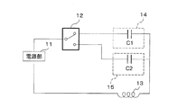
Next, with reference to FIG. 2, a specific configuration of the switching
図2に示すように、整合回路をコンデンサで構成した場合、送電側コイル13とコンデンサとが共振する周波数において、インピーダンスが最も小さくなる(直列共振回路に流れる電流が最も大きくなる)。送電側コイル13の周辺の媒質変化により、直列共振回路における共振周波数やインピーダンスが変化するため、この媒質変化に応じて、切替部12が、適宜、整合回路を切り替える。
As shown in FIG. 2, when the matching circuit is composed of a capacitor, the impedance is the smallest (the current flowing through the series resonant circuit is the largest) at the frequency at which the
例えば、整合回路14における静電容量C1は、送電側コイル13が空気中に存在する場合における共振周波数と、電源部11から出力される交流電流の周波数とが一致するように、設定される。
For example, the capacitance C1 in the
また、例えば、整合回路15における静電容量C2は、送電側コイル13が水中に存在する場合における共振周波数と、電源部11から出力される交流電流の周波数とが一致するように、設定される。
Further, for example, the capacitance C2 in the
従って、切替部12は、送電側コイル13の周辺の媒質が空気から水へと変化した場合、選択する整合回路を、静電容量C1を有するコンデンサから静電容量C2を有するコンデンサへと切り替える。あるいは、切替部12は、送電側コイル13の周辺の媒質が水から空気へと変化した場合、選択する整合回路を、静電容量C2を有するコンデンサへから静電容量C1を有するコンデンサへと切り替える。
Therefore, when the medium around the
これにより、送電側コイル13の周辺の媒質が変化しても、各々の媒質中に存在する場合における送電側コイル13の共振周波数と、電源部11から出力される交流電流の周波数とを一致させることができる。従って、前記のように、無線給電装置100において、周辺の媒質が変化しても、高効率な給電を行うことが可能になる。
As a result, even if the medium around the power
なお、本実施形態では、送電装置1又は受電装置2に、整合回路を、それぞれ2つずつ搭載する構成を一例に挙げて説明するが、整合回路の個数は、特に限定されるものではない。
In the present embodiment, a configuration in which two matching circuits are mounted on the power transmitting device 1 or the
例えば、送電装置1又は受電装置2に、異なる回路定数(静電容量C1,C2,C3)を有する3つのコンデンサを、並列に接続して搭載しても良い。この場合、各コンデンサを組み合わせることにより、静電容量C1、静電容量C2、静電容量C3、静電容量(C1+C2)、静電容量(C1+C3)、静電容量(C2+C3)、静電容量(C1+C2+C3)、という7種類の整合回路を構成することが可能である。つまり、この場合には、7種類の媒質変化に対応した無線給電装置の提供が可能である。
For example, three capacitors having different circuit constants (capacitances C1, C2, C3) may be connected and mounted in parallel on the power transmission device 1 or the
〔インピーダンス特性〕
次に、図3を参照して、水中及び空気中における送電側コイル13のインピーダンス特性について説明する。なお、水中及び空気中における受電側コイル23のインピーダンス特性についても、同様であるため、説明を省略する。
[Impedance characteristics]
Next, with reference to FIG. 3, the impedance characteristics of the power
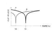
図3は、周波数とインピーダンスとの関係を示すグラフの一例である。横軸は周波数[Hz]を、縦軸はインピーダンス[Ω]を表している。 FIG. 3 is an example of a graph showing the relationship between frequency and impedance. The horizontal axis represents frequency [Hz] and the vertical axis represents impedance [Ω].
グラフAは、空気中に存在する送電側コイル13とコンデンサとを直列に接続した場合におけるインピーダンスの周波数特性の一例である。グラフBは、水中に存在する送電側コイル13とコンデンサとを直列に接続した場合におけるインピーダンスの周波数特性の一例である。
Graph A is an example of the frequency characteristics of impedance when the power
グラフAにおける周波数fr1は、送電側コイル13が空気中に存在する場合の共振周波数である。グラフBにおける周波数fr2は、送電側コイル13が水中に存在する場合の共振周波数である。
The frequency fr1 in the graph A is a resonance frequency when the power
図3から、送電側コイル13が空気中に存在する場合の共振周波数fr1は、送電側コイル13が水中に存在する場合の共振周波数fr2と比較して大きいことがわかる。つまり、送電側コイル13の周辺の媒質が変化すると、送電側コイル13の共振周波数も変化する。共振周波数がずれると、送電装置から受電装置へと、効率の良い送電を行うことができないため、媒質変化に応じて、整合回路を適宜選択することが必要になる。
From FIG. 3, it can be seen that the resonance frequency fr1 when the power
また、図3から、送電側コイル13が、空気中に存在する場合も、水中に存在する場合も、インピーダンスは、共振周波数において、最も小さいことがわかる。電源部11から出力される交流電流の周波数と、送電側コイル13の共振周波数とを、一致させることで、送電側コイル13に流れる電流を最も大きくすることができる。つまり、送電装置から受電装置へと、効率の良い送電を行うためには、電源部11から出力される交流電流の周波数と、送電側コイル13の共振周波数とを、一致させることが必要になる。
Further, from FIG. 3, it can be seen that the impedance is the smallest at the resonance frequency regardless of whether the power
ここで、送電側コイル13の周辺の媒質が変化した場合における、インピーダンスの虚部の整合と、インピーダンスの実部の整合について説明する。なお、受電側コイル23の周辺の媒質が変化した場合についても、同様に説明することができる。
Here, the matching of the imaginary part of the impedance and the matching of the real part of the impedance when the medium around the
インピーダンスの虚部については、図2に示すように、コンデンサの静電容量を調整することで、整合が可能である。送電側コイル13の周辺の媒質変化に応じて、コンデンサの静電容量を、静電容量C1から静電容量C2へと、あるいは静電容量C2から静電容量C1へと、変化させることで、直列共振回路における共振周波数を調整し、インピーダンスの虚部を整合することができる。
As shown in FIG. 2, the imaginary part of the impedance can be matched by adjusting the capacitance of the capacitor. By changing the capacitance of the capacitor from the capacitance C1 to the capacitance C2 or from the capacitance C2 to the capacitance C1 according to the change of the medium around the
インピーダンスの実部については、例えば、電源部11と送電側コイル13との間にトランス(変成器)を挿入し、コイルの巻数比を調整することで、整合が可能である。送電側コイル13の周辺の媒質変化に応じて、巻数比を、空気中で整合する巻数比から水中で整合する巻数比へと、あるいは水中で整合する巻数比から空気中で整合する巻数比へと、変化させることで、インピーダンスの実部を整合することができる。
Matching is possible by inserting a transformer (transformer) between the
インピーダンスの虚部だけでなく、インピーダンスの実部についても整合を行うことで、より高精度なインピーダンス整合が可能になる。これにより、無線給電装置100における伝送効率を更に高めることができる。
By matching not only the imaginary part of the impedance but also the real part of the impedance, more accurate impedance matching becomes possible. Thereby, the transmission efficiency in the wireless
〔コイルの線間容量〕
次に、図4を参照して、送電側コイル13に生じる線間容量について説明する。なお、受電側コイル23に生じる線間容量についても、同様に説明することができる。
[Coil line capacitance]
Next, with reference to FIG. 4, the line capacitance generated in the power
図4に示すように、送電側コイル13は、筐体130に収容される。筐体130の内部には、電界131が発生し、線間容量132が定まる。筐体130の外部には、電界133が発生し、線間容量134が定まる。線間容量132と線間容量134との和が、送電側コイル13に生じる線間容量となる。
As shown in FIG. 4, the power
線間容量134は、媒質Xの誘電率に依存する。空気の比誘電率は約1であり、水の比誘電率は約80である。従って、媒質Xが、水である場合における送電側コイル13の線間容量134は、媒質Xが、空気である場合における送電側コイル13の線間容量134と比較して大きくなる。
The
従って、媒質Xが、水である場合における送電側コイル13の線間容量(線間容量132と線間容量134との和)も、媒質Xが、空気である場合における送電側コイル13の線間容量(線間容量132と線間容量134との和)と比較して大きくなる。
Therefore, the line capacitance (sum of the
つまり、送電側コイル13の周辺の媒質Xが変化すると、送電側コイル13の線間容量が変化し、送電側コイル13の共振周波数も変化する。媒質Xが、水である場合における送電側コイル13の共振周波数は、媒質Xが、空気である場合における送電側コイル13の共振周波数と比較して小さくなる。
That is, when the medium X around the power
〔媒質判定用センサ及び検出回路の構成〕
次に、図5,図6を参照して、媒質判定用センサ17及び検出回路18の具体的な構成について説明する。なお、媒質判定用センサ27及び検出回路28についても、同様の構成とすることができるため、説明を省略する。
[Configuration of medium determination sensor and detection circuit]
Next, a specific configuration of the
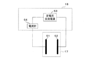
図5に示す方法は、電極間を流れる電流を測定し、送電側コイル13の周辺の媒質を特定する方法である。
The method shown in FIG. 5 is a method of measuring the current flowing between the electrodes and specifying the medium around the
媒質判定用センサ17として、電極51、電極52を使用する。電極51と電極52とは、媒質を介して、対向して設けられる。検出回路18として、定電圧交流電源53、電流計54を使用する。電極51は、電流計54と接続され、電極52は、定電圧交流電源53と接続される。
The
電極51、電極52には、定電圧交流電源53から定電圧が印加され、電流計54は、電極51と電極52との間を流れる電流を測定する。
A constant voltage is applied to the
送電側コイル13の周辺の媒質が変化すると、電極51と電極52との間を流れる電流も変化する。媒質判定用センサ17及び検出回路18は、この変化に基づいて、送電側コイル13の周辺の媒質を特定する。
When the medium around the
図6に示す方法は、超音波センサ間の受信強度を測定し、送電側コイル13の周辺の媒質を特定する方法である。
The method shown in FIG. 6 is a method of measuring the reception intensity between the ultrasonic sensors and identifying the medium around the
媒質判定用センサ17として、超音波センサ61、超音波センサ62を使用する。超音波センサ61と超音波センサ62とは、媒質を介して、対向して設けられる。検出回路18として、超音波発振器63、検波回路64、電圧計65を使用する。超音波センサ61は、超音波発振器63と接続され、超音波センサ62は、検波回路64、電圧計65と接続される。
An
超音波発振器63は、予め設定された周波数の電気信号を、超音波センサ61へと出力する。超音波センサ61は、超音波発振器63から入力される電気信号を、音響信号に変換する。超音波センサ62は、超音波センサ61から到達した音響信号を、電気信号に変換し、検波回路64へと出力する。検波回路64は、超音波センサ62から入力される電気信号を検波し、検波した電気信号を、電圧計65へと出力する。電圧計65は、検波回路64により検波された電気信号を、受信強度として測定する。
The
送電側コイル13の周辺の媒質が変化すると、超音波センサ61と超音波センサ62との間の音響インピーダンスが変化し、受信強度も変化する。媒質判定用センサ17及び検出回路18は、この変化に基づいて、送電側コイル13の周辺の媒質を特定する。
When the medium around the
なお、媒質判定用センサの構成は、上述の電極51、電極52、超音波センサ61、超音波センサ62、等に限定されるものではない。
The configuration of the medium determination sensor is not limited to the above-mentioned
例えば、媒質判定用センサとして、塩分濃度検出センサを用いても良い。この場合、送電側コイル13の周辺の媒質における塩分濃度が変化しても、無線給電装置100は、高効率な給電を行うことができる。
For example, a salt concentration detection sensor may be used as the medium determination sensor. In this case, even if the salt concentration in the medium around the
また、例えば、媒質判定用センサとして、電気抵抗検出センサを用いても良い。この場合、安価な構成で、無線給電装置100は、高効率な給電を行うことができる。
Further, for example, an electric resistance detection sensor may be used as the medium determination sensor. In this case, the wireless
上述の構成を有する無線給電装置100は、例えば、原子力プラントの水中作業用ロボット、海中探査装置、水中遠隔操縦船舶、等に適用することが可能である。
The wireless
本実施形態に係る無線給電装置100によれば、送電装置及び受電装置のそれぞれに、媒質判定部を設け、切替部が、判定結果に基づいて整合回路を切り替えることで、各装置におけるインピーダンスを調整することができる。これにより、無線給電装置100は、周辺の媒質が変化しても、高効率な給電を行うことができる。
According to the wireless
また、本実施の形態に係る無線給電装置100によれば、ロボット等を遠隔操作する操縦者が、送電コイル又は受電コイルの周辺の媒質を判断し、媒質変化に応じて、整合回路を切り替えるという操作を行う必要がない。従って、操縦者の負担を軽減しつつ、高効率な給電が可能な無線給電装置を提供することができる。
Further, according to the wireless
また、本実施の形態に係る無線給電装置100によれば、インピーダンスを調整するために、送電装置と受電装置との間で、通信を行う必要がない。従って、無線給電装置100が、例えば、空気中から水中へと移動する際に、電磁波が遮断されて通信が途絶し、伝送効率が低下するという従来の無線給電装置に発生していた問題を改善できる。
Further, according to the wireless
〔無線給電装置の動作〕
次に、図1を参照して、本発明の実施形態に係る無線給電装置100の動作について簡単に説明する。
[Operation of wireless power supply device]
Next, with reference to FIG. 1, the operation of the wireless
無線給電装置100が、空気中から水中へと移動する場合の動作を、一例に挙げて説明する。
The operation when the wireless
まず、送電側コイル13は、電源部11から交流電流を供給され、磁束を発生する。
First, the power
無線給電装置100は、空気中に存在するため、電源部11は、整合回路14と接続され、整合回路14は、電源部11から出力される交流電流の周波数と、空気中における送電側コイル13の共振周波数とを整合する。
Since the wireless
ここで、無線給電装置100が、空気中から水中へと移動すると、媒質判定部16は、送電側コイル13の周辺の媒質を検出し、該媒質が、水であると判定する。
Here, when the wireless
切替部12は、媒質判定部16による判定結果(送電側コイル13の周辺の媒質が、水であるという判定結果)に基づいて、電源部11と接続する整合回路を、整合回路14から整合回路15へと切り替える。
The switching
電源部11は、整合回路15と接続され、整合回路15は、電源部11から出力される交流電流の周波数と、水中における送電側コイル13の共振周波数とを整合する。
The
これにより、無線給電装置100が、空気中から水中へと移動しても、送電装置1において、高効率な送電が可能になる。
As a result, even if the wireless
一方、受電側コイル23は、送電側コイル13に発生する磁束と鎖交し、誘導電流を、負荷30へと供給する。
On the other hand, the power receiving
無線給電装置100は、空気中に存在するため、負荷30は、整合回路24と接続され、整合回路24は、電源部11から出力される交流電流の周波数と、空気中における受電側コイル23の共振周波数とを整合する。
Since the wireless
ここで、無線給電装置100が、空気中から水中へと移動すると、媒質判定部26は、受電側コイル23の周辺の媒質を検出し、該媒質が、水であると判定する。
Here, when the wireless
切替部22は、媒質判定部26による判定結果(受電側コイル23の周辺の媒質が、水であるという判定結果)に基づいて、負荷30と接続する整合回路を、整合回路24から整合回路25へと切り替える。
The switching
負荷30は、整合回路25と接続され、整合回路25は、電源部11から出力される交流電流の周波数と、水中における受電側コイル23の共振周波数とを整合する。
The
従って、無線給電装置100が、空気中から水中へと移動しても、受電装置2において、高効率な受電が可能になる。
Therefore, even if the wireless
以上の動作によって、無線給電装置100は、周辺の媒質が変化しても、高効率な給電を行うことができる。
By the above operation, the wireless
≪第2実施形態≫
[無線給電装置の全体構成]
次に、図7を参照して、本発明の第2実施形態に係る無線給電装置200の構成について説明する。
<< Second Embodiment >>
[Overall configuration of wireless power supply device]
Next, the configuration of the wireless
図7に示すように、無線給電装置200は、送電装置201と、受電装置202と、を備える。無線給電装置200において、送電装置201から受電装置202へと、非接触で電力が伝送され、受電装置202から負荷30(例えば、二次電池、電動駆動装置)へと、電力が供給される。
As shown in FIG. 7, the wireless
送電装置201に設けられる送電側コイルに、交流電流が流れると、送電側コイルに磁束が発生する。該磁束が、送電側共振コイル、受電側共振コイルを介して、受電装置2に設けられる受電側コイルと鎖交することにより、受電側コイルに、誘導電流が流れる。送電側共振コイルの共振周波数と受電側共振コイルの共振周波数とが近い程、伝送効率は高くなる。
When an alternating current flows through the power transmission side coil provided in the
〔送電装置の構成〕
図7に示すように、送電装置201は、電源部11、切替部(送電側切替部)12、送電側コイル113、共振コイル(送電側共振コイル)114、整合回路(送電側整合回路)14、整合回路(送電側整合回路)15、媒質判定部(送電側媒質判定部)16、を備える。媒質判定部16は、媒質判定用センサ17、検出回路18、判定回路19、を備える。本実施形態では、電源部11、切替部12、送電側コイル113、共振コイル(送電側共振コイル)114、整合回路14、整合回路15、媒質判定部16、検出回路18、判定回路19は、送電装置201の筐体内に設けられる。また、媒質判定用センサ17は、送電装置201の筐体外に設けられる。
[Structure of power transmission device]
As shown in FIG. 7, the
電源部11、切替部12、整合回路14、整合回路15、媒質判定部16の構成については、第1実施形態に係る送電装置1と同様の構成であるため、第1実施形態を参酌することができる。
Since the configurations of the
送電側コイル113は、電源部11と接続される。送電側コイル113は、電源部11から交流電流が供給されることで、磁束を発生する。
The power
共振コイル114は、送電側コイル113と所定の間隔をおいて、送電側コイル113と略同軸上に設けられ、切替部12、整合回路14及び整合回路15と接続される。共振コイル114は、周辺の媒質に依存せずに、使用できるようにするため、ハウジングや筐体に収容される。送電側コイル113と共振コイル114とは、電磁的に結合する。
The
送電装置201において、送電側コイル113と共振コイル114とを変成器として機能させることができる。送電側コイル113と共振コイル114との間隔を変更することで、送電装置201におけるインピーダンスの実部の整合が可能である。即ち、周辺の媒質変化に応じて、送電側コイル113と共振コイル114との間隔を、空気中で整合する間隔から水中で整合する間隔へと、あるいは水中で整合する間隔から空気中で整合する間隔へと、変化させることで、インピーダンスの実部を整合することができる。
In the
例えば、予め送電側コイルとの間隔が定まった水中用の送電側共振コイル及び空気中用の送電側共振コイルを、送電装置201に搭載し、媒質判定部16による判定結果に基づいて、切替部12が、どちらかの送電側共振コイルを選択し、インピーダンスの実部を整合することも可能である。
For example, an underwater power transmission side resonance coil and an air power transmission side resonance coil whose spacing from the power transmission side coil is predetermined are mounted on the
また、例えば、送電側コイル113と共振コイル114との間隔を変更できる機構を、送電装置201に搭載し、媒質判定部16による判定結果に基づいて、間隔を変更し、インピーダンスの実部を整合することも可能である。なお、インピーダンスの虚部については、第1実施形態に示した説明を参酌できる。
Further, for example, a mechanism capable of changing the distance between the power
整合回路14,15と併せて、送電側コイル113及び共振コイル114を、インピーダンスの整合に利用することで、無線給電装置200における伝送効率を更に高めることができる。
By using the
〔受電装置の構成〕
図7に示すように、受電装置202は、整流部21、切替部(受電側切替部)22、受電側コイル123、共振コイル(受電側共振コイル)124、整合回路(受電側整合回路)24、整合回路(受電側整合回路)25、媒質判定部(受電側媒質判定部)26、を備える。媒質判定部26は、媒質判定用センサ27、検出回路28、判定回路29、を備える。本実施形態では、整流部21、切替部22、受電側コイル123、共振コイル(受電側共振コイル)124、整合回路24、整合回路25、媒質判定部26、検出回路28、判定回路29は、受電装置202の筐体内に設けられる。また、媒質判定用センサ27は、受電装置202の筐体外に設けられる。
[Configuration of power receiving device]
As shown in FIG. 7, the
整流部21、切替部22、整合回路24、整合回路25、媒質判定部26の構成については、第1実施形態に係る受電装置2と同様の構成であるため、第1実施形態を参酌することができる。
Since the configurations of the rectifying
共振コイル124は、切替部22、整合回路24及び整合回路25と接続される。共振コイル124は、周辺の媒質に依存せずに、使用できるようにするため、ハウジングや筐体に収容される。共振コイル114と共振コイル124とは共振し、送電装置201から受電装置202へと、電力が伝送される。共振コイル114と共振コイル124との共振周波数が一致すると、送電装置201から受電装置202へと効率良く電力を伝送できる。
The
受電側コイル123は、共振コイル124と所定の間隔をおいて、共振コイル124と略同軸上に設けられ、整流部21、負荷30と接続される。受電側コイル123は、共振コイル114、共振コイル124を介して、送電側コイル113に発生した磁束と鎖交する。これにより、受電側コイル123には、誘導電流が流れ、受電側コイル123は、該誘導電流を、負荷30へと供給する。また、受電側コイル123と共振コイル124とは、電磁的に結合する。
The power receiving
受電装置202において、受電側コイル123と共振コイル124とを変成器として機能させることができる。受電側コイル123と共振コイル124との間隔を変更することで、受電装置202におけるインピーダンスの実部の整合が可能である。即ち、周辺の媒質変化に応じて、受電側コイル123と共振コイル124との間隔を、空気中で整合する間隔から水中で整合する間隔へと、あるいは水中で整合する間隔から空気中で整合する間隔へと、変化させることで、インピーダンスの実部を整合することができる。
In the
例えば、予め受電側コイルとの間隔が定まった水中用の受電側共振コイル及び空気中用の受電側共振コイルを、受電装置202に搭載し、媒質判定部26による判定結果に基づいて、切替部22が、どちらかの受電側共振コイルを選択し、インピーダンスの実部を整合することも可能である。
For example, a power receiving side resonance coil for underwater and a power receiving side resonance coil for air in which the distance from the power receiving side coil is determined in advance are mounted on the
また、例えば、受電側コイル123と共振コイル124との間隔を変更できる機構を、受電装置202に搭載し、媒質判定部26による判定結果に基づいて、間隔を変更し、インピーダンスの実部を整合することも可能である。なお、インピーダンスの虚部については、第1実施形態に示した説明を参酌できる。
Further, for example, a mechanism capable of changing the interval between the power receiving
整合回路24,25と併せて、受電側コイル123及び共振コイル124を、インピーダンスの整合に利用することで、無線給電装置200における伝送効率を更に高めることができる。
By using the power receiving
100,200 無線給電装置
1 送電装置
2 受電装置
11 電源部
12 切替部(送電側切替部)
13,113 送電側コイル
14,15 整合回路(送電側整合回路)
16 媒質判定部(送電側媒質判定部)
22 切替部(受電側切替部)
23,123 送電側コイル
24,25 整合回路(受電側整合回路)
26 媒質判定部(受電側媒質判定部)
30 負荷
114 共振コイル(送電側共振コイル)
124 共振コイル(受電側共振コイル)
100,200 Wireless power supply device 1
13,113
16 Medium determination unit (transmission side medium determination unit)
22 Switching unit (power receiving side switching unit)
23,123
26 Medium determination unit (power receiving side medium determination unit)
30
124 Resonant coil (Resonant coil on the power receiving side)
Claims (8)
前記送電装置は、
電源部から交流電流を供給されて、磁束を発生する送電側コイルと、
前記電源部から出力される交流電流の周波数と、前記送電側コイルの共振周波数とを整合する送電側整合回路と、
前記送電側コイルの周辺の媒質を判定する送電側媒質判定部と、
該送電側媒質判定部の判定に基づいて、複数の前記送電側整合回路の中から、前記電源部と接続する所定の送電側整合回路へと切り替える送電側切替部と、
を備え、
前記受電装置は、
前記磁束と鎖交して、負荷へと誘導電流を供給する受電側コイルと、
前記電源部から出力される交流電流の周波数と、前記受電側コイルの共振周波数とを整合する受電側整合回路と、
前記受電側コイルの周辺の媒質を判定する受電側媒質判定部と、
該受電側媒質判定部の判定に基づいて、複数の前記受電側整合回路の中から、前記負荷と接続する所定の受電側整合回路へと切り替える受電側切替部と、
を備えることを特徴とする無線給電装置。 A wireless power supply device that transmits power from a power transmission device to a power reception device in a non-contact manner.
The power transmission device
A coil on the power transmission side that generates magnetic flux by supplying alternating current from the power supply unit,
A power transmission side matching circuit that matches the frequency of the alternating current output from the power supply unit with the resonance frequency of the power transmission side coil.
A power transmission side medium determination unit that determines the medium around the power transmission side coil, and
A power transmission side switching unit that switches from a plurality of the power transmission side matching circuits to a predetermined power transmission side matching circuit connected to the power supply unit based on the determination of the power transmission side medium determination unit.
With
The power receiving device is
A power receiving coil that interlinks with the magnetic flux and supplies an induced current to the load,
A power receiving side matching circuit that matches the frequency of the alternating current output from the power supply unit with the resonance frequency of the power receiving coil.
A power receiving side medium determination unit that determines the medium around the power receiving side coil, and
A power receiving side switching unit that switches from a plurality of the power receiving side matching circuits to a predetermined power receiving side matching circuit connected to the load based on the determination of the power receiving side medium determination unit.
A wireless power supply device characterized by being provided with.
前記受電側コイルと電磁的に結合し、前記送電側共振コイルと共振する受電側共振コイルと、を更に備え、
前記送電側整合回路は、前記電源部から出力される交流電流の周波数と、前記送電側共振コイルの共振周波数とを整合し、
前記送電側媒質判定部は、前記送電側共振コイルの周辺の媒質を判定し、
前記受電側整合回路は、前記電源部から出力される交流電流の周波数と、前記受電側共振コイルの共振周波数とを整合し、
前記受電側媒質判定部は、前記受電側共振コイルの周辺の媒質を判定する、
ことを特徴とする請求項1に記載の無線給電装置。 A power transmission side resonance coil that is electromagnetically coupled to the power transmission side coil,
A power receiving side resonance coil that is electromagnetically coupled to the power receiving side coil and resonates with the power transmitting side resonance coil is further provided.
The power transmission side matching circuit matches the frequency of the alternating current output from the power supply unit with the resonance frequency of the power transmission side resonance coil.
The power transmission side medium determination unit determines the medium around the power transmission side resonance coil, and determines the medium.
The power receiving side matching circuit matches the frequency of the alternating current output from the power supply unit with the resonance frequency of the power receiving side resonance coil.
The power receiving side medium determination unit determines the medium around the power receiving side resonance coil.
The wireless power feeding device according to claim 1.
ことを特徴とする請求項1又は2に記載の無線給電装置。 The power transmission side matching circuit and the power receiving side matching circuit are capacitors.
The wireless power feeding device according to claim 1 or 2.
ことを特徴とする請求項1に記載の無線給電装置。 The power transmission side matching circuit and the power receiving side matching circuit are capacitors and transformers.
The wireless power feeding device according to claim 1.
前記受電側コイルと前記受電側共振コイルとの間隔は変更可能である、
ことを特徴とする請求項2に記載の無線給電装置。 The distance between the power transmission side coil and the power transmission side resonance coil can be changed.
The distance between the power receiving side coil and the power receiving side resonance coil can be changed.
The wireless power feeding device according to claim 2.
ことを特徴とする請求項1に記載の無線給電装置。 The transmission side medium determination unit and the power reception side medium determination unit measure any one of the conductivity, sound velocity, acoustic impedance, density, buoyancy, dielectric constant, viscosity, and refractive index of the medium.
The wireless power feeding device according to claim 1.
送電側コイルが、電源部から交流電流を供給されて、磁束を発生するステップと、
送電側整合回路が、前記電源部から出力される交流電流の周波数と、前記送電側コイルの共振周波数とを整合するステップと、
送電側媒質判定部が、前記送電側コイルの周辺の媒質を判定するステップと、
送電側切替部が、前記送電側媒質判定部の判定に基づいて、複数の前記送電側整合回路の中から、前記電源部と接続する所定の送電側整合回路へと切り替えるステップと、
受電側コイルが、前記磁束と鎖交して、負荷へと誘導電流を供給するステップと、
受電側整合回路が、前記電源部から出力される交流電流の周波数と、前記受電側コイルの共振周波数とを整合するステップと、
受電側媒質判定部が、前記受電側コイルの周辺の媒質を判定するステップと、
受電側切替部が、前記受電側媒質判定部の判定に基づいて、複数の前記受電側整合回路の中から、前記負荷と接続する所定の受電側整合回路へと切り替えるステップと、
を備えることを特徴とする無線給電方法。 It is a wireless power supply method that transmits power from a power transmission device to a power reception device in a non-contact manner.
The step that the coil on the power transmission side is supplied with alternating current from the power supply to generate magnetic flux,
A step in which the power transmission side matching circuit matches the frequency of the alternating current output from the power supply unit with the resonance frequency of the power transmission side coil.
The step in which the transmission side medium determination unit determines the medium around the transmission side coil,
A step in which the power transmission side switching unit switches from a plurality of the power transmission side matching circuits to a predetermined power transmission side matching circuit connected to the power supply unit based on the determination of the power transmission side medium determination unit.
A step in which the power receiving coil interlinks with the magnetic flux to supply an induced current to the load.
A step in which the power receiving side matching circuit matches the frequency of the alternating current output from the power supply unit with the resonance frequency of the power receiving side coil.
A step in which the power receiving side medium determination unit determines the medium around the power receiving side coil,
A step in which the power receiving side switching unit switches from a plurality of the power receiving side matching circuits to a predetermined power receiving side matching circuit connected to the load based on the determination of the power receiving side medium determination unit.
A wireless power supply method characterized by comprising.
送電側コイルが、電源部から交流電流を供給されて、磁束を発生するステップと、
送電側共振コイルが、前記送電側コイルと、電磁的に結合するステップと、
送電側整合回路が、前記電源部から出力される交流電流の周波数と、前記送電側共振コイルの共振周波数とを整合するステップと、
送電側媒質判定部が、前記送電側共振コイルの周辺の媒質を判定するステップと、
送電側切替部が、前記送電側媒質判定部の判定に基づいて、複数の前記送電側整合回路の中から、前記電源部と接続する所定の送電側整合回路へと切り替えるステップと、
受電側共振コイルが、前記送電側共振コイルと共振するステップと、
受電側コイルが、前記受電側共振コイルと電磁的に結合し、前記磁束と鎖交して、負荷へと誘導電流を供給するステップと、
受電側整合回路が、前記電源部から出力される交流電流の周波数と、前記受電側共振コイルの共振周波数とを整合するステップと、
受電側媒質判定部が、前記受電側共振コイルの周辺の媒質を判定するステップと、
受電側切替部が、前記受電側媒質判定部の判定に基づいて、複数の前記受電側整合回路の中から、前記負荷と接続する所定の受電側整合回路へと切り替えるステップと、
を備えることを特徴とする無線給電方法。 It is a wireless power supply method that transmits power from a power transmission device to a power reception device in a non-contact manner.
The step that the coil on the power transmission side is supplied with alternating current from the power supply to generate magnetic flux,
A step in which the power transmission side resonance coil is electromagnetically coupled to the power transmission side coil.
A step in which the power transmission side matching circuit matches the frequency of the alternating current output from the power supply unit with the resonance frequency of the power transmission side resonance coil.
The step in which the transmission side medium determination unit determines the medium around the transmission side resonance coil,
A step in which the power transmission side switching unit switches from a plurality of the power transmission side matching circuits to a predetermined power transmission side matching circuit connected to the power supply unit based on the determination of the power transmission side medium determination unit.
The step in which the power receiving side resonance coil resonates with the power transmission side resonance coil,
A step in which the power receiving side coil electromagnetically couples with the power receiving side resonance coil, interlinks with the magnetic flux, and supplies an induced current to the load.
A step in which the power receiving side matching circuit matches the frequency of the alternating current output from the power supply unit with the resonance frequency of the power receiving side resonance coil.
A step in which the power receiving side medium determination unit determines the medium around the power receiving side resonance coil,
A step in which the power receiving side switching unit switches from a plurality of the power receiving side matching circuits to a predetermined power receiving side matching circuit connected to the load based on the determination of the power receiving side medium determination unit.
A wireless power supply method characterized by comprising.
Priority Applications (1)
| Application Number | Priority Date | Filing Date | Title |
|---|---|---|---|
| JP2016220775A JP6842885B2 (en) | 2016-11-11 | 2016-11-11 | Wireless power supply device and wireless power supply method |
Applications Claiming Priority (1)
| Application Number | Priority Date | Filing Date | Title |
|---|---|---|---|
| JP2016220775A JP6842885B2 (en) | 2016-11-11 | 2016-11-11 | Wireless power supply device and wireless power supply method |
Publications (3)
| Publication Number | Publication Date |
|---|---|
| JP2018078773A JP2018078773A (en) | 2018-05-17 |
| JP2018078773A5 JP2018078773A5 (en) | 2019-10-10 |
| JP6842885B2 true JP6842885B2 (en) | 2021-03-17 |
Family
ID=62149322
Family Applications (1)
| Application Number | Title | Priority Date | Filing Date |
|---|---|---|---|
| JP2016220775A Active JP6842885B2 (en) | 2016-11-11 | 2016-11-11 | Wireless power supply device and wireless power supply method |
Country Status (1)
| Country | Link |
|---|---|
| JP (1) | JP6842885B2 (en) |
Families Citing this family (2)
| Publication number | Priority date | Publication date | Assignee | Title |
|---|---|---|---|---|
| JP7263954B2 (en) * | 2019-07-12 | 2023-04-25 | 株式会社Ihi | power supply system |
| CN112886719A (en) * | 2021-01-29 | 2021-06-01 | 国网江西省电力有限公司电力科学研究院 | Wireless charging system of inspection robot and passive continuous impedance adjusting method thereof |
Family Cites Families (6)
| Publication number | Priority date | Publication date | Assignee | Title |
|---|---|---|---|---|
| JP2011155732A (en) * | 2010-01-26 | 2011-08-11 | Equos Research Co Ltd | Noncontact power transmission system and noncontact power transmission device |
| US9559550B2 (en) * | 2011-02-15 | 2017-01-31 | Toyota Jidosha Kabushiki Kaisha | Contactless power receiving apparatus and vehicle incorporating same, contactless power feeding facility, method of controlling contactless power receiving apparatus, and method of controlling contactless power feeding facility |
| US20140111138A1 (en) * | 2012-10-18 | 2014-04-24 | Qualcomm Incorporated | Position-based car mode activation |
| US10038342B2 (en) * | 2013-05-15 | 2018-07-31 | Nec Corporation | Power transfer system with shielding body, power transmitting device with shielding body, and power transfer method for power transmitting system |
| WO2015115041A1 (en) * | 2014-01-29 | 2015-08-06 | 日本電気株式会社 | Wireless power transmission control device, wireless power transmission system, and wireless power transmission control method |
| JP2015213428A (en) * | 2015-06-24 | 2015-11-26 | 日東電工株式会社 | Wireless power supply system |
-
2016
- 2016-11-11 JP JP2016220775A patent/JP6842885B2/en active Active
Also Published As
| Publication number | Publication date |
|---|---|
| JP2018078773A (en) | 2018-05-17 |
Similar Documents
| Publication | Publication Date | Title |
|---|---|---|
| KR101338654B1 (en) | Apparatus for transmitting wireless power, apparatus for receiving wireless power, system for transmitting wireless power and method for transmitting wireless power | |
| JP4911148B2 (en) | Contactless power supply | |
| TWI559340B (en) | Wireless power transmitter and method of transmitting power thereof | |
| CN108092416B (en) | Wireless power transmitter and method of controlling power thereof | |
| KR101543059B1 (en) | Wireless power receiving device and power control method thereof | |
| US20140203662A1 (en) | Wireless power repeater and method thereof | |
| KR20120050011A (en) | Resonance power transmission system and method to control resonance power transmitting and receiving | |
| JP2012143091A (en) | Remotely and wirelessly driven charger | |
| KR20130033867A (en) | Wireless power transmission system | |
| GB2599283A (en) | Systems and methods for wireless power transmission in a well | |
| JP2019513342A (en) | System and method for wireless power transfer | |
| JP2012023913A (en) | Non-contact power feeding device | |
| JP6842885B2 (en) | Wireless power supply device and wireless power supply method | |
| TWI417910B (en) | Electromagnetic apparatus using shared flux in a multi-load parallel magnetic circuit and method of operation | |
| JP2014124019A (en) | Wireless power transmission system | |
| US20210305846A1 (en) | Power receiving device, power transmitting device, and underwater power supply system | |
| JP6717381B2 (en) | Wireless power feeding device and wireless power feeding method | |
| KR20150123711A (en) | Wireless power trasmission method using inphase feeding with dual loops and apparatus using the method | |
| KR101822213B1 (en) | Apparatus for transmitting wireless power, apparatus for receiving wireless power, system for transmitting wireless power and method for transmitting wireless power | |
| JP6760806B2 (en) | Wireless power supply | |
| KR101305828B1 (en) | Apparatus for transmitting wireless power, apparatus for receiving wireless power, system for transmitting wireless power and method for transmitting wireless power | |
| KR101806116B1 (en) | Resonant inductive distance measuring equipment | |
| KR101360744B1 (en) | Apparatus for transmitting wireless power, apparatus for receiving wireless power, system for transmitting wireless power and method for transmitting wireless power | |
| KR101896944B1 (en) | Wireless power receiving device and power control method thereof | |
| KR102183127B1 (en) | Wireless apparatus for transmitting power |
Legal Events
| Date | Code | Title | Description |
|---|---|---|---|
| A521 | Written amendment |
Free format text: JAPANESE INTERMEDIATE CODE: A523 Effective date: 20190902 |
|
| A621 | Written request for application examination |
Free format text: JAPANESE INTERMEDIATE CODE: A621 Effective date: 20190902 |
|
| A977 | Report on retrieval |
Free format text: JAPANESE INTERMEDIATE CODE: A971007 Effective date: 20200626 |
|
| A131 | Notification of reasons for refusal |
Free format text: JAPANESE INTERMEDIATE CODE: A131 Effective date: 20200804 |
|
| A521 | Written amendment |
Free format text: JAPANESE INTERMEDIATE CODE: A523 Effective date: 20200909 |
|
| TRDD | Decision of grant or rejection written | ||
| A01 | Written decision to grant a patent or to grant a registration (utility model) |
Free format text: JAPANESE INTERMEDIATE CODE: A01 Effective date: 20210216 |
|
| A61 | First payment of annual fees (during grant procedure) |
Free format text: JAPANESE INTERMEDIATE CODE: A61 Effective date: 20210222 |
|
| R150 | Certificate of patent or registration of utility model |
Ref document number: 6842885 Country of ref document: JP Free format text: JAPANESE INTERMEDIATE CODE: R150 |