EP3413374A1 - Vehicle battery pack and automobile comprising same - Google Patents
Vehicle battery pack and automobile comprising same Download PDFInfo
- Publication number
- EP3413374A1 EP3413374A1 EP17865108.9A EP17865108A EP3413374A1 EP 3413374 A1 EP3413374 A1 EP 3413374A1 EP 17865108 A EP17865108 A EP 17865108A EP 3413374 A1 EP3413374 A1 EP 3413374A1
- Authority
- EP
- European Patent Office
- Prior art keywords
- pack
- connector
- battery pack
- circuit board
- static electricity
- Prior art date
- Legal status (The legal status is an assumption and is not a legal conclusion. Google has not performed a legal analysis and makes no representation as to the accuracy of the status listed.)
- Granted
Links
Images




Classifications
-
- H—ELECTRICITY
- H01—ELECTRIC ELEMENTS
- H01M—PROCESSES OR MEANS, e.g. BATTERIES, FOR THE DIRECT CONVERSION OF CHEMICAL ENERGY INTO ELECTRICAL ENERGY
- H01M50/00—Constructional details or processes of manufacture of the non-active parts of electrochemical cells other than fuel cells, e.g. hybrid cells
- H01M50/20—Mountings; Secondary casings or frames; Racks, modules or packs; Suspension devices; Shock absorbers; Transport or carrying devices; Holders
-
- H—ELECTRICITY
- H01—ELECTRIC ELEMENTS
- H01M—PROCESSES OR MEANS, e.g. BATTERIES, FOR THE DIRECT CONVERSION OF CHEMICAL ENERGY INTO ELECTRICAL ENERGY
- H01M10/00—Secondary cells; Manufacture thereof
- H01M10/04—Construction or manufacture in general
- H01M10/0486—Frames for plates or membranes
-
- B—PERFORMING OPERATIONS; TRANSPORTING
- B60—VEHICLES IN GENERAL
- B60L—PROPULSION OF ELECTRICALLY-PROPELLED VEHICLES; SUPPLYING ELECTRIC POWER FOR AUXILIARY EQUIPMENT OF ELECTRICALLY-PROPELLED VEHICLES; ELECTRODYNAMIC BRAKE SYSTEMS FOR VEHICLES IN GENERAL; MAGNETIC SUSPENSION OR LEVITATION FOR VEHICLES; MONITORING OPERATING VARIABLES OF ELECTRICALLY-PROPELLED VEHICLES; ELECTRIC SAFETY DEVICES FOR ELECTRICALLY-PROPELLED VEHICLES
- B60L50/00—Electric propulsion with power supplied within the vehicle
- B60L50/50—Electric propulsion with power supplied within the vehicle using propulsion power supplied by batteries or fuel cells
- B60L50/60—Electric propulsion with power supplied within the vehicle using propulsion power supplied by batteries or fuel cells using power supplied by batteries
- B60L50/64—Constructional details of batteries specially adapted for electric vehicles
-
- B—PERFORMING OPERATIONS; TRANSPORTING
- B60—VEHICLES IN GENERAL
- B60L—PROPULSION OF ELECTRICALLY-PROPELLED VEHICLES; SUPPLYING ELECTRIC POWER FOR AUXILIARY EQUIPMENT OF ELECTRICALLY-PROPELLED VEHICLES; ELECTRODYNAMIC BRAKE SYSTEMS FOR VEHICLES IN GENERAL; MAGNETIC SUSPENSION OR LEVITATION FOR VEHICLES; MONITORING OPERATING VARIABLES OF ELECTRICALLY-PROPELLED VEHICLES; ELECTRIC SAFETY DEVICES FOR ELECTRICALLY-PROPELLED VEHICLES
- B60L50/00—Electric propulsion with power supplied within the vehicle
- B60L50/50—Electric propulsion with power supplied within the vehicle using propulsion power supplied by batteries or fuel cells
- B60L50/60—Electric propulsion with power supplied within the vehicle using propulsion power supplied by batteries or fuel cells using power supplied by batteries
- B60L50/66—Arrangements of batteries
-
- B—PERFORMING OPERATIONS; TRANSPORTING
- B60—VEHICLES IN GENERAL
- B60L—PROPULSION OF ELECTRICALLY-PROPELLED VEHICLES; SUPPLYING ELECTRIC POWER FOR AUXILIARY EQUIPMENT OF ELECTRICALLY-PROPELLED VEHICLES; ELECTRODYNAMIC BRAKE SYSTEMS FOR VEHICLES IN GENERAL; MAGNETIC SUSPENSION OR LEVITATION FOR VEHICLES; MONITORING OPERATING VARIABLES OF ELECTRICALLY-PROPELLED VEHICLES; ELECTRIC SAFETY DEVICES FOR ELECTRICALLY-PROPELLED VEHICLES
- B60L58/00—Methods or circuit arrangements for monitoring or controlling batteries or fuel cells, specially adapted for electric vehicles
- B60L58/10—Methods or circuit arrangements for monitoring or controlling batteries or fuel cells, specially adapted for electric vehicles for monitoring or controlling batteries
- B60L58/18—Methods or circuit arrangements for monitoring or controlling batteries or fuel cells, specially adapted for electric vehicles for monitoring or controlling batteries of two or more battery modules
- B60L58/22—Balancing the charge of battery modules
-
- H—ELECTRICITY
- H01—ELECTRIC ELEMENTS
- H01M—PROCESSES OR MEANS, e.g. BATTERIES, FOR THE DIRECT CONVERSION OF CHEMICAL ENERGY INTO ELECTRICAL ENERGY
- H01M10/00—Secondary cells; Manufacture thereof
- H01M10/04—Construction or manufacture in general
- H01M10/0481—Compression means other than compression means for stacks of electrodes and separators
-
- H—ELECTRICITY
- H01—ELECTRIC ELEMENTS
- H01M—PROCESSES OR MEANS, e.g. BATTERIES, FOR THE DIRECT CONVERSION OF CHEMICAL ENERGY INTO ELECTRICAL ENERGY
- H01M10/00—Secondary cells; Manufacture thereof
- H01M10/42—Methods or arrangements for servicing or maintenance of secondary cells or secondary half-cells
- H01M10/425—Structural combination with electronic components, e.g. electronic circuits integrated to the outside of the casing
-
- H—ELECTRICITY
- H01—ELECTRIC ELEMENTS
- H01M—PROCESSES OR MEANS, e.g. BATTERIES, FOR THE DIRECT CONVERSION OF CHEMICAL ENERGY INTO ELECTRICAL ENERGY
- H01M50/00—Constructional details or processes of manufacture of the non-active parts of electrochemical cells other than fuel cells, e.g. hybrid cells
- H01M50/20—Mountings; Secondary casings or frames; Racks, modules or packs; Suspension devices; Shock absorbers; Transport or carrying devices; Holders
- H01M50/271—Lids or covers for the racks or secondary casings
-
- H—ELECTRICITY
- H01—ELECTRIC ELEMENTS
- H01M—PROCESSES OR MEANS, e.g. BATTERIES, FOR THE DIRECT CONVERSION OF CHEMICAL ENERGY INTO ELECTRICAL ENERGY
- H01M50/00—Constructional details or processes of manufacture of the non-active parts of electrochemical cells other than fuel cells, e.g. hybrid cells
- H01M50/20—Mountings; Secondary casings or frames; Racks, modules or packs; Suspension devices; Shock absorbers; Transport or carrying devices; Holders
- H01M50/284—Mountings; Secondary casings or frames; Racks, modules or packs; Suspension devices; Shock absorbers; Transport or carrying devices; Holders with incorporated circuit boards, e.g. printed circuit boards [PCB]
-
- H—ELECTRICITY
- H01—ELECTRIC ELEMENTS
- H01M—PROCESSES OR MEANS, e.g. BATTERIES, FOR THE DIRECT CONVERSION OF CHEMICAL ENERGY INTO ELECTRICAL ENERGY
- H01M50/00—Constructional details or processes of manufacture of the non-active parts of electrochemical cells other than fuel cells, e.g. hybrid cells
- H01M50/20—Mountings; Secondary casings or frames; Racks, modules or packs; Suspension devices; Shock absorbers; Transport or carrying devices; Holders
- H01M50/298—Mountings; Secondary casings or frames; Racks, modules or packs; Suspension devices; Shock absorbers; Transport or carrying devices; Holders characterised by the wiring of battery packs
-
- H—ELECTRICITY
- H01—ELECTRIC ELEMENTS
- H01M—PROCESSES OR MEANS, e.g. BATTERIES, FOR THE DIRECT CONVERSION OF CHEMICAL ENERGY INTO ELECTRICAL ENERGY
- H01M50/00—Constructional details or processes of manufacture of the non-active parts of electrochemical cells other than fuel cells, e.g. hybrid cells
- H01M50/50—Current conducting connections for cells or batteries
- H01M50/543—Terminals
-
- H—ELECTRICITY
- H01—ELECTRIC ELEMENTS
- H01M—PROCESSES OR MEANS, e.g. BATTERIES, FOR THE DIRECT CONVERSION OF CHEMICAL ENERGY INTO ELECTRICAL ENERGY
- H01M10/00—Secondary cells; Manufacture thereof
- H01M10/42—Methods or arrangements for servicing or maintenance of secondary cells or secondary half-cells
- H01M10/425—Structural combination with electronic components, e.g. electronic circuits integrated to the outside of the casing
- H01M2010/4271—Battery management systems including electronic circuits, e.g. control of current or voltage to keep battery in healthy state, cell balancing
-
- H—ELECTRICITY
- H01—ELECTRIC ELEMENTS
- H01M—PROCESSES OR MEANS, e.g. BATTERIES, FOR THE DIRECT CONVERSION OF CHEMICAL ENERGY INTO ELECTRICAL ENERGY
- H01M10/00—Secondary cells; Manufacture thereof
- H01M10/42—Methods or arrangements for servicing or maintenance of secondary cells or secondary half-cells
- H01M10/425—Structural combination with electronic components, e.g. electronic circuits integrated to the outside of the casing
- H01M2010/4278—Systems for data transfer from batteries, e.g. transfer of battery parameters to a controller, data transferred between battery controller and main controller
-
- H—ELECTRICITY
- H01—ELECTRIC ELEMENTS
- H01M—PROCESSES OR MEANS, e.g. BATTERIES, FOR THE DIRECT CONVERSION OF CHEMICAL ENERGY INTO ELECTRICAL ENERGY
- H01M2200/00—Safety devices for primary or secondary batteries
-
- H—ELECTRICITY
- H01—ELECTRIC ELEMENTS
- H01M—PROCESSES OR MEANS, e.g. BATTERIES, FOR THE DIRECT CONVERSION OF CHEMICAL ENERGY INTO ELECTRICAL ENERGY
- H01M2220/00—Batteries for particular applications
- H01M2220/20—Batteries in motive systems, e.g. vehicle, ship, plane
-
- H—ELECTRICITY
- H01—ELECTRIC ELEMENTS
- H01R—ELECTRICALLY-CONDUCTIVE CONNECTIONS; STRUCTURAL ASSOCIATIONS OF A PLURALITY OF MUTUALLY-INSULATED ELECTRICAL CONNECTING ELEMENTS; COUPLING DEVICES; CURRENT COLLECTORS
- H01R13/00—Details of coupling devices of the kinds covered by groups H01R12/70 or H01R24/00 - H01R33/00
- H01R13/648—Protective earth or shield arrangements on coupling devices, e.g. anti-static shielding
- H01R13/6485—Electrostatic discharge protection
-
- Y—GENERAL TAGGING OF NEW TECHNOLOGICAL DEVELOPMENTS; GENERAL TAGGING OF CROSS-SECTIONAL TECHNOLOGIES SPANNING OVER SEVERAL SECTIONS OF THE IPC; TECHNICAL SUBJECTS COVERED BY FORMER USPC CROSS-REFERENCE ART COLLECTIONS [XRACs] AND DIGESTS
- Y02—TECHNOLOGIES OR APPLICATIONS FOR MITIGATION OR ADAPTATION AGAINST CLIMATE CHANGE
- Y02E—REDUCTION OF GREENHOUSE GAS [GHG] EMISSIONS, RELATED TO ENERGY GENERATION, TRANSMISSION OR DISTRIBUTION
- Y02E60/00—Enabling technologies; Technologies with a potential or indirect contribution to GHG emissions mitigation
- Y02E60/10—Energy storage using batteries
-
- Y—GENERAL TAGGING OF NEW TECHNOLOGICAL DEVELOPMENTS; GENERAL TAGGING OF CROSS-SECTIONAL TECHNOLOGIES SPANNING OVER SEVERAL SECTIONS OF THE IPC; TECHNICAL SUBJECTS COVERED BY FORMER USPC CROSS-REFERENCE ART COLLECTIONS [XRACs] AND DIGESTS
- Y02—TECHNOLOGIES OR APPLICATIONS FOR MITIGATION OR ADAPTATION AGAINST CLIMATE CHANGE
- Y02P—CLIMATE CHANGE MITIGATION TECHNOLOGIES IN THE PRODUCTION OR PROCESSING OF GOODS
- Y02P70/00—Climate change mitigation technologies in the production process for final industrial or consumer products
- Y02P70/50—Manufacturing or production processes characterised by the final manufactured product
-
- Y—GENERAL TAGGING OF NEW TECHNOLOGICAL DEVELOPMENTS; GENERAL TAGGING OF CROSS-SECTIONAL TECHNOLOGIES SPANNING OVER SEVERAL SECTIONS OF THE IPC; TECHNICAL SUBJECTS COVERED BY FORMER USPC CROSS-REFERENCE ART COLLECTIONS [XRACs] AND DIGESTS
- Y02—TECHNOLOGIES OR APPLICATIONS FOR MITIGATION OR ADAPTATION AGAINST CLIMATE CHANGE
- Y02T—CLIMATE CHANGE MITIGATION TECHNOLOGIES RELATED TO TRANSPORTATION
- Y02T10/00—Road transport of goods or passengers
- Y02T10/60—Other road transportation technologies with climate change mitigation effect
- Y02T10/70—Energy storage systems for electromobility, e.g. batteries
-
- Y—GENERAL TAGGING OF NEW TECHNOLOGICAL DEVELOPMENTS; GENERAL TAGGING OF CROSS-SECTIONAL TECHNOLOGIES SPANNING OVER SEVERAL SECTIONS OF THE IPC; TECHNICAL SUBJECTS COVERED BY FORMER USPC CROSS-REFERENCE ART COLLECTIONS [XRACs] AND DIGESTS
- Y02—TECHNOLOGIES OR APPLICATIONS FOR MITIGATION OR ADAPTATION AGAINST CLIMATE CHANGE
- Y02T—CLIMATE CHANGE MITIGATION TECHNOLOGIES RELATED TO TRANSPORTATION
- Y02T10/00—Road transport of goods or passengers
- Y02T10/60—Other road transportation technologies with climate change mitigation effect
- Y02T10/7072—Electromobility specific charging systems or methods for batteries, ultracapacitors, supercapacitors or double-layer capacitors
-
- Y—GENERAL TAGGING OF NEW TECHNOLOGICAL DEVELOPMENTS; GENERAL TAGGING OF CROSS-SECTIONAL TECHNOLOGIES SPANNING OVER SEVERAL SECTIONS OF THE IPC; TECHNICAL SUBJECTS COVERED BY FORMER USPC CROSS-REFERENCE ART COLLECTIONS [XRACs] AND DIGESTS
- Y02—TECHNOLOGIES OR APPLICATIONS FOR MITIGATION OR ADAPTATION AGAINST CLIMATE CHANGE
- Y02T—CLIMATE CHANGE MITIGATION TECHNOLOGIES RELATED TO TRANSPORTATION
- Y02T90/00—Enabling technologies or technologies with a potential or indirect contribution to GHG emissions mitigation
- Y02T90/10—Technologies relating to charging of electric vehicles
- Y02T90/12—Electric charging stations
-
- Y—GENERAL TAGGING OF NEW TECHNOLOGICAL DEVELOPMENTS; GENERAL TAGGING OF CROSS-SECTIONAL TECHNOLOGIES SPANNING OVER SEVERAL SECTIONS OF THE IPC; TECHNICAL SUBJECTS COVERED BY FORMER USPC CROSS-REFERENCE ART COLLECTIONS [XRACs] AND DIGESTS
- Y02—TECHNOLOGIES OR APPLICATIONS FOR MITIGATION OR ADAPTATION AGAINST CLIMATE CHANGE
- Y02T—CLIMATE CHANGE MITIGATION TECHNOLOGIES RELATED TO TRANSPORTATION
- Y02T90/00—Enabling technologies or technologies with a potential or indirect contribution to GHG emissions mitigation
- Y02T90/10—Technologies relating to charging of electric vehicles
- Y02T90/14—Plug-in electric vehicles
-
- Y—GENERAL TAGGING OF NEW TECHNOLOGICAL DEVELOPMENTS; GENERAL TAGGING OF CROSS-SECTIONAL TECHNOLOGIES SPANNING OVER SEVERAL SECTIONS OF THE IPC; TECHNICAL SUBJECTS COVERED BY FORMER USPC CROSS-REFERENCE ART COLLECTIONS [XRACs] AND DIGESTS
- Y02—TECHNOLOGIES OR APPLICATIONS FOR MITIGATION OR ADAPTATION AGAINST CLIMATE CHANGE
- Y02T—CLIMATE CHANGE MITIGATION TECHNOLOGIES RELATED TO TRANSPORTATION
- Y02T90/00—Enabling technologies or technologies with a potential or indirect contribution to GHG emissions mitigation
- Y02T90/10—Technologies relating to charging of electric vehicles
- Y02T90/16—Information or communication technologies improving the operation of electric vehicles
Definitions
- static electricity may be generated internally.
- static electricity generated outside the battery pack may enter the battery pack depending on external environment factors. For example, if an electrostatic discharge (ESD) phenomenon occurs outside the battery pack due to any factor, static electricity can be introduced into the battery pack through an air venting port of a battery pack case.
- ESD electrostatic discharge
- static electricity generated at the outside may be introduced into the battery pack through positive and negative electrode terminals exposed to the outside of the pack case, or by means of a metallic fastening member such as a bolt which is frequently used for assembling the pack case.
- the pack case may further include a cell assembly having a plurality of secondary batteries and end plates located at top and bottom portions of the cell assembly to support the cell assembly; and a ground wire configured to electrically connect the BMS circuit board and the end plates.
- a wire mounting unit may be provided at the BMS circuit board so that one end of the ground wire is fixed thereto, and the wire mounting unit may be located on the static electricity inducing pattern.
- a battery pack of the present disclosure as described below may be provided to a vehicle as an energy source of the vehicle.
- the battery pack may be provided to an electric vehicle, a hybrid vehicle, a plug-in hybrid vehicle, and the like.
- the battery pack may also be provided to other devices, instruments, facilities or the like such as an energy storage system.
- the pack case 100 forms an appearance of the battery pack 10 and may be mounted to an electric vehicle 20.
- the pack case 100 may be composed of an upper case 110 and a lower case 120.
- the lower case 120 is configured to have an inner space in which the cell assembly 200, the end plates 300 and other electric components assembled into a single body may be accommodated, and the upper case 110 is configured to cover a top portion of the lower case 120.
- the end plates 300 may be provided approximately in a plate form with a large area and may cover the top and bottom portions of the cell assembly 200.
- the end plates 300 may include a lower plate 320 disposed at the bottom portion of the cell assembly 200 and an upper plate 310 disposed above the lower plate 320 with the cell assembly 200 being interposed therebetween.
- the cable connector 600 for both communicating and grounding may include a pack connector 610, a vehicle connector 620, and a harness cable 630 for connecting them.
- the pack connector 610 includes a first connection portion 611 and a second connection portion 612.
- the first connection portion 611 may be a component that is connected to the data transmission terminal P1
- the second connection portion 612 may be a component that is connected to the discharge terminal P2.
- the static electricity inducing pattern 510 includes a first inducing pattern 511 connected to the pack connector 610 and a second inducing pattern 512 connected to the static electricity discharge filter 530, based on the wire mounting unit 520.
- the current supplied to the BMS circuit board 500 from outside may flow in both directions along the first inducing pattern 511 and the second inducing pattern 512.
- the static electricity discharge filter 530 may perform electrostatic discharge and the cable connector 600 for both communicating and grounding may emit static electricity to the outside and ground the vehicle body of the vehicle, simultaneously.
Landscapes
- Engineering & Computer Science (AREA)
- Chemical & Material Sciences (AREA)
- Chemical Kinetics & Catalysis (AREA)
- Electrochemistry (AREA)
- General Chemical & Material Sciences (AREA)
- Manufacturing & Machinery (AREA)
- Sustainable Energy (AREA)
- Sustainable Development (AREA)
- Life Sciences & Earth Sciences (AREA)
- Power Engineering (AREA)
- Transportation (AREA)
- Mechanical Engineering (AREA)
- Microelectronics & Electronic Packaging (AREA)
- Battery Mounting, Suspending (AREA)
- Electric Propulsion And Braking For Vehicles (AREA)
- Charge And Discharge Circuits For Batteries Or The Like (AREA)
Abstract
Description
- The present disclosure relates to a battery pack, and more particularly, to a battery pack capable of preventing damage to electric components such as a BMS circuit built in the battery pack when an electrostatic discharge (ESD) occurs inside or outside the battery pack.
- The present application claims priority to Korean Patent Application No.
10-2016-0138552 filed on October 24, 2016 - In recent years, secondary batteries have been widely used not only for small-sized devices such as portable electronic devices but also for electric vehicles that require a driving force by using an internal combustion engine and/or an electric motor. The electric vehicle includes a hybrid vehicle, a plug-in hybrid vehicle, and a pure electric vehicle driven only by an electric motor and a battery without an internal combustion engine.
- In an electric vehicle, a large number of secondary batteries are electrically connected to increase capacity and output. Particularly, pouch-type secondary batteries are commonly used in such medium or large devices since they are easily stackable on one another.
- Secondary batteries widely used at the preset include lithium ion batteries, lithium polymer batteries, nickel cadmium batteries, nickel hydrogen batteries, nickel zinc batteries and the like. An operating voltage of the unit secondary battery cell, namely a unit battery cell, is about 2.5V to 4.2V. Therefore, if a higher output voltage is required, a plurality of battery cells may be connected in series to configure a battery pack. In addition, depending on the charge/discharge capacity required for the battery pack, a plurality of battery cells may be connected in parallel to configure a battery pack. The number of battery cells included in the battery pack may be variously set according to the required output voltage or the demanded charge/discharge capacity.
- Meanwhile, while the battery pack is outputting or recharging power required of a vehicle, static electricity may be generated internally. In addition, static electricity generated outside the battery pack may enter the battery pack depending on external environment factors. For example, if an electrostatic discharge (ESD) phenomenon occurs outside the battery pack due to any factor, static electricity can be introduced into the battery pack through an air venting port of a battery pack case. In addition, static electricity generated at the outside may be introduced into the battery pack through positive and negative electrode terminals exposed to the outside of the pack case, or by means of a metallic fastening member such as a bolt which is frequently used for assembling the pack case.
- If the static electricity generated inside the battery pack or introduced from the outside is accumulated in the battery pack, an electronic device affected by the static electricity is highly likely to malfunction without any apparent reason. In particular, if the BMS circuit responsible for charging/discharging and overall control of the battery pack is damaged or fails, the stability of the battery pack may be seriously damaged.
- The present disclosure is designed to solve the problems of the related art, and therefore the present disclosure is directed to a battery pack, which may prevent static electricity from being accumulated in the battery pack when an electrostatic discharge (ESD) occurs inside or outside the battery pack, so that electronic devices such as a BMS circuit are not damaged.
- However, the technical objects aimed by the present disclosure are not limited to the above, and other objects not mentioned herein will be apparently understood from the following description by those skilled in the art.
- In one aspect of the present disclosure, there is provided a battery pack for a vehicle, comprising: a pack case forming an appearance of the battery pack; a static electricity inducing pattern forming a conductor pattern of a predetermined form on a BMS circuit board provided in the pack case and a discharge terminal connected to the static electricity inducing pattern; and a cable connector for both communicating and grounding, which is composed of a pack connector having a first connection portion configured to be connected to a data transmission terminal on the BMS circuit board and a second connection portion configured to be connected to the discharge terminal, and a vehicle connector connected to the pack connector by a harness cable and installed to the pack case to be exposed out through a connector mounting hole formed through the pack case.
- The pack connector may include a first pack connector and a second pack connector independently provided to be separated from the first pack connector, and the first connection portion may be defined by the first pack connector, and the second connection portion may be defined by the second pack connector.
- The pack case may further include a cell assembly having a plurality of secondary batteries and end plates located at top and bottom portions of the cell assembly to support the cell assembly; and a ground wire configured to electrically connect the BMS circuit board and the end plates.
- A wire mounting unit may be provided at the BMS circuit board so that one end of the ground wire is fixed thereto, and the wire mounting unit may be located on the static electricity inducing pattern.
- The wire mounting unit may be provided to a corner region of the BMS circuit board, and the static electricity inducing pattern may be formed along an edge region of the BMS circuit board.
- A static electricity discharge filter configured as a passive element may be provided at the BMS circuit board, and the static electricity inducing pattern may include a first inducing pattern connected to the pack connector on the basis of the wire mounting unit and a second inducing pattern connected to the static electricity discharge filter.
- The end plates may include a lower plate disposed at the bottom portion of the cell assembly and an upper plate disposed above the lower plate with the cell assembly being interposed therebetween, and a long bolt member connected to the upper plate, the cell assembly and the lower plate to assemble the upper plate, the cell assembly and the lower plate into a single body may be further provided.
- The BMS circuit board may be mounted to an insulating frame and located at an upper surface of the upper plate.
- The pack case may include a lower case configured to form an inner space capable of accommodating the end plates and the cell assembly and an upper case configured to cover a top portion of the lower case, and the connector mounting hole may be provided at the upper case.
- The long bolt member may pass through a bolt-coupling hole vertically formed in the upper case and assemble the upper case, the upper plate, the cell assembly and the lower plate into a single body.
- The data transmission terminal and the discharge terminal may be selected from a plurality of pins regularly arranged on the BMS circuit board at regular intervals, and the pack connector may be provided in a single number, and the first connection portion and the second connection portion may be provided as conductors which individually come into contact with the pins.
- In another aspect of the present disclosure, there is also provided a vehicle including the battery pack described above. The vehicle may comprise a ground line configured to electrically connect the vehicle connector of the battery pack to a vehicle body.
- In an embodiment of the present disclosure, it is possible to provide a battery pack, which may prevent static electricity from being accumulated in the battery pack when an electrostatic discharge (ESD) occurs inside or outside the battery pack, so that electronic devices such as a BMS circuit are not damaged.
- Furthermore, in another embodiment of the present disclosure, it is possible to achieve efficiency and economic feasibility by using an existing communication cable connector of a vehicle, which is wired from the inside of the battery pack to the outside thereof, for both communicating and grounding.
- The accompanying drawings illustrate a preferred embodiment of the present disclosure and together with the foregoing disclosure, serve to provide further understanding of the technical features of the present disclosure, and thus, the present disclosure is not construed as being limited to the drawing.
-
FIG. 1 is a perspective view showing a battery pack according to an embodiment of the present disclosure. -
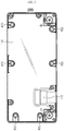
FIG. 2 is a top view ofFIG. 1 . -
FIG. 3 is a perspective view showing the battery pack ofFIG. 1 , from which an upper case and a cable connector for both communicating and grounding are separated. -
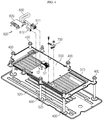
FIGS. 4 and5 are perspective views before and after main components according to an embodiment of the present disclosure are combined. -
FIG. 6 is a rear view schematically showing only a main configuration of the BMS circuit board ofFIG. 5 . -
FIG. 7 is a partially enlarged view ofFIG. 5 . -
FIG. 8 is a schematic view showing a grounding configuration of a vehicle and a battery pack according to an embodiment of the present disclosure. -
FIG. 9 is a rear view showing only a main configuration of a BMS circuit board according to another embodiment of the present disclosure. -
FIG. 10 is a perspective view showing a cable connector for both communicating and grounding according to still another embodiment of the present disclosure. -
FIG. 11 is a rear view schematically showing only a main configuration of a BMS circuit board according to still another embodiment of the present disclosure. - Hereinafter, preferred embodiments of the present disclosure will be described in detail with reference to the accompanying drawings. Prior to the description, it should be understood that the terms used in the specification and the appended claims should not be construed as limited to general and dictionary meanings, but interpreted based on the meanings and concepts corresponding to technical aspects of the present disclosure on the basis of the principle that the inventor is allowed to define terms appropriately for the best explanation.
- Therefore, the description proposed herein is just a preferable example for the purpose of illustrations only, not intended to limit the scope of the disclosure, so it should be understood that other equivalents and modifications could be made thereto without departing from the scope of the disclosure.
- Since the embodiments disclosed herein are provided for more perfect explanation of the present disclosure, the shape, size and the like of components may be exaggerated, omitted or simplified in the drawings for better understanding. Thus, the size and ratio of components in the drawings do not wholly reflect the actual size and ratio.
- A battery pack of the present disclosure as described below may be provided to a vehicle as an energy source of the vehicle. For example, the battery pack may be provided to an electric vehicle, a hybrid vehicle, a plug-in hybrid vehicle, and the like. In addition to the vehicle, the battery pack may also be provided to other devices, instruments, facilities or the like such as an energy storage system.
-
FIG. 1 is a perspective view showing a battery pack according to an embodiment of the present disclosure,FIG. 2 is a top view ofFIG. 1 ,FIG. 3 is a perspective view showing the battery pack ofFIG. 1 , from which an upper case and a cable connector for both communicating and grounding are separated, andFIGS. 4 and5 are perspective views before and after main components according to an embodiment of the present disclosure are combined. - Referring to
FIGS. 1 to 5 , abattery pack 10 according to an embodiment of the present disclosure includes apack case 100, acell assembly 200 accommodated in thepack case 100,end plates 300 located at top and bottom portions of thecell assembly 200, along bolt member 400 for assembling the above components into a single body, aBMS circuit board 500 located at a top surface of theend plate 300, acable connector 600 for both communicating and grounding connected to theBMS circuit board 500, and aground wire 700. - The
pack case 100 forms an appearance of thebattery pack 10 and may be mounted to anelectric vehicle 20. Thepack case 100 may be composed of anupper case 110 and alower case 120. Thelower case 120 is configured to have an inner space in which thecell assembly 200, theend plates 300 and other electric components assembled into a single body may be accommodated, and theupper case 110 is configured to cover a top portion of thelower case 120. - An electrode terminal coupling hole 122 and a long bolt-
coupling hole 111 may be formed in theupper case 110. Positive and negative electrode terminals of thebattery pack 10 may pass through the electrode terminal coupling hole 122 and be exposed above thepack case 100. In addition, the positive and negative electrode terminals of thebattery pack 10 may be connected to a power cable which leads to a drive motor of a vehicle. As explained later, along bolt member 400 for assembling theupper case 110, theend plates 300 and thecell assembly 200 into a single body may be inserted into the long bolt-coupling hole 111 in a downward direction. A head portion of thelong bolt member 400 may be formed to have a larger diameter than the long bolt-coupling hole 111 so as to press theupper case 110 and be exposed out of theupper case 110. - As shown in
FIGS. 1 to 5 , aconnector mounting hole 113 may be further formed in theupper case 110. One end of thecable connector 600 for both communicating and grounding is mounted in theconnector mounting hole 113, and thecable connector 600 for both communicating and grounding may be connected to acommunication line 24 and aground line 22 out of thebattery pack 10. - Battery information may be transmitted to devices in or out of the vehicle through the
communication line 24, and a driver may visually check the battery information such as temperature, state of charge or discharge through a display device. In addition, thecable connector 600 for both communicating and grounding may be used for grounding static electricity inside thebattery pack 10, which will be described in detail later. - The
cell assembly 200 may include a plurality of secondary batteries and a cartridge for stacking the plurality of secondary batteries, although not shown in detail for convenience of illustration. - Briefly describing the
cell assembly 200, thecell assembly 200 may be substantially an aggregation of a plurality of secondary batteries. The secondary batteries may be pouch-type secondary batteries which have high energy density and be easy stacked. Since the pouch-type secondary batteries lack mechanical rigidity, a cartridge may be used to hold the secondary batteries and prevent them from moving. The cartridge may include a stacking frame of a rectangular ring shape and a cooling plate mounted thereto. For example, at least one secondary battery cell is placed on an upper surface of any one cartridge, then another cartridge is placed thereon, and then the upper and lower cartridges are assembled there to in a snap-fit manner. Thecell assembly 200 may be configured by stacking secondary batteries and cartridges in a vertical direction as described above. - Referring to
FIGS. 4 and5 along withFIG. 3 , theend plates 300 may be provided approximately in a plate form with a large area and may cover the top and bottom portions of thecell assembly 200. In more detail, theend plates 300 may include alower plate 320 disposed at the bottom portion of thecell assembly 200 and anupper plate 310 disposed above thelower plate 320 with thecell assembly 200 being interposed therebetween. - The
end plate 300 may protect thecell assembly 200 from an external impact or the like. Thus, theend plate 300 may be made of a metal material such as steel to ensure rigidity. - The
upper plate 310, thecell assembly 200 and thelower plate 320 may be assembled into a single body by thelong bolt member 400. For example, theupper plate 310 has a hole through which thelong bolt member 400 may be inserted, and thelower plate 320 has a groove below the hole so that a thread of thelong bolt member 400 may be coupled thereto. For reference,FIGS. 4 and5 depict only the upper andlower end plates 300, except for thecell assembly 200. However, thecell assembly 200 may be positioned between theupper plate 310 and thelower plate 320. Thecell assembly 200 also has a hole into which thelong bolt member 400 is inserted in a vertical direction. Thus, thelong bolt member 400 may pass through the holes of theupper plate 310 and thecell assembly 200 and be coupled to the groove on theupper plate 310. By doing so, theupper plate 310, thecell assembly 200 and thelower plate 320 are integrally assembled to ensure firm coupling among them. - The components assembled into a single body by the
long bolt member 400 may be limited to theupper plate 310, thecell assembly 200 and thelower plate 320 as described above, or theupper case 110 may be added to the single body as in this embodiment. For example, theupper case 110 has the long bolt-coupling hole 111 at a location corresponding to a vertical upper portion of the hole of theupper plate 310, as described above. Thelong bolt member 400 passes through the long bolt-coupling hole 111 in a vertical direction and is connected to theupper case 110, theupper plate 310, thecell assembly 200 and thelower plate 320 to assemble them into a single body. At this time, the top surface of theupper case 110 may be pressed downward by the head portion of thelong bolt member 400. - Since the
upper case 110 is assembled with theupper plate 310, thecell assembly 200 and thelower plate 320 into a single body as described above, it is possible to enhance the coupling force and airtightness of theupper case 110 to thelower case 120. - Referring to
FIGS. 3 to 5 again, theBMS circuit board 500 of this embodiment may be located at the top of theupper plate 310. In addition to theBMS circuit board 500, other electric components such as a relay assembly and a plurality of bus bars may be located on theupper plate 310. Other electric components including the BMS circuit board 500 (seeFIG. 3 ) may be mounted on aninsulation board 800 made of an insulating material. - The
insulation board 800 serves as an insulator between the electric components including theBMS circuit board 500 and theupper plate 310 made of metal and provides a place where theBMS circuit board 500 and the electric components may be assembled. Theinsulation board 800 may also have a hole into which thelong bolt member 400 may be inserted so as to be integrally assembled with theupper case 110, theupper plate 310, thecell assembly 200 and thelower plate 320, similarly to the above. - Meanwhile, the battery management system (BMS) refers to a battery management device that controls overall charging and discharging operations of the secondary batteries and may be regarded as a component that is typically included in the
battery pack 10. The BMS may be implemented as a printed circuit board on which a control circuit is printed, and various elements such as a memory, a capacitor, a resistor and a diode may be intensively mounted on theBMS circuit board 500. - Particularly, on the
BMS circuit board 500 according to an embodiment of the present disclosure, as shown inFIG. 6 , a data transmission terminal P1 for transmitting battery information to an external device and a discharge terminal P2 connected to a staticelectricity inducing pattern 510 forming a conductor pattern of a predetermined type may be further provided. - When static electricity is generated to supply a current to the
BMS circuit board 500, the staticelectricity inducing pattern 510 induces the current to thecable connector 600 for both communicating and grounding sides. The staticelectricity inducing pattern 510 may be formed along an edge of theBMS circuit board 500 to bypass the BMS circuit and other elements in order to minimize electrical interference with the BMS circuitry and other components. The discharge terminal P2 may be located at one end of the staticelectricity inducing pattern 510. - The discharge terminal P2 may be formed at a position spaced apart from the data transmission terminal P1 by a predetermined distance, which may minimize mutual noise by giving the distance between the discharge terminal P2 and the data transmission terminal P1. The discharge terminal P2 and the data transmission terminal P1 may be electrically connected to the
cable connector 600 for both communicating and grounding. - Referring to
FIGS. 4 and5 again, thecable connector 600 for both communicating and grounding may include apack connector 610, avehicle connector 620, and aharness cable 630 for connecting them. - First, the
vehicle connector 620 may be fixedly mounted to theconnector mounting hole 113 provided in theupper case 110 in a snap-fit manner. Thevehicle connector 620 may be connected to aseparate harness cable 630 connector outside thebattery pack 10. Here, a portion of the cable may be wired along the communication line and another portion of the cable may be grounded to avehicle body 26 along theground line 22. - The
harness cable 630 electrically connects thevehicle connector 620 and thepack connector 610 by using a bundle of wires which are classified according to usages such as data transmission and grounding. The bundle of wires may be protected in a single thick sheath. Meanwhile, in this embodiment, theharness cable 630 is divided into two halves, one connected to thefirst pack connector 611 and the other connected to thesecond pack connector 612. - The
pack connector 610 includes afirst connection portion 611 and asecond connection portion 612. Here, thefirst connection portion 611 may be a component that is connected to the data transmission terminal P1, and thesecond connection portion 612 may be a component that is connected to the discharge terminal P2. - In detail, as shown in
FIGS. 4 and5 , thepack connector 610 may be implemented with two connectors, namely afirst pack connector 611 and asecond pack connector 612. Here, thefirst connection portion 611 may be defined as afirst pack connector 611, and thefirst pack connector 611 may be inserted into a data transmission socket S1 and connected to the data transmission terminal P1. Also, thesecond connection portion 612 may be defined as asecond pack connector 612, and thesecond pack connector 612 may be plugged into a discharge terminal socket S2 and connected to the discharge terminal P2. - As described above, the
pack connector 610 of this embodiment may be divided into two connectors having separate uses and may be individually connected to the data transmission terminal P1 and the discharge terminal P2. In other words, thefirst connection portion 611 and thesecond connection portion 612 of this embodiment are connected to the data transmission terminal P1 and the discharge terminal P2, respectively, in a structurally separated state, which may minimize the electrical noise or impact between them. - In addition, if the
cable connector 600 for both communicating and grounding and the discharging terminal P2 are used, when static electricity is generated in thebattery pack 10 to supply current to theBMS circuit board 500, the current may flow out of thebattery pack 10 after passing through the staticelectricity inducing pattern 510, the discharge terminal P2, thesecond pack connector 612, theharness cable 630 and thevehicle connector 620 in order. Also, the current may be grounded to thevehicle body 26 of the vehicle along theground line 22 outside thebattery pack 10. - Moreover, the
battery pack 10 according to the present disclosure may further include aground wire 700 for electrically connecting theBMS circuit board 500 and theend plate 300. - As shown in
FIGS. 5 and7 , one end of theground wire 700 may be fixed to awire mounting unit 520 of theBMS circuit board 500, and the other end thereof may be fixed to a wire-coupling protrusion of theend plate 300. In this embodiment, theground wire 700 is fixed using screws and nuts, but other similar fastening means may also be used. - In this embodiment, a
single ground wire 700 is used to connect theBMS circuit board 500 and theend plate 300, and accordingly a singlewire mounting unit 520 is provided and positioned on the staticelectricity inducing pattern 510. However, unlike this embodiment, it is possible that two ormore ground wires 700 are installed, and accordingly two or morewire mounting units 520 may also be provided. - As described above, the
end plate 300 includes upper andlower plates lower plates long bolt member 400. Theend plate 300 may serve as a ground in thebattery pack 10. In other words, since theend plate 300 forms a relatively large resistor than the BMS circuit, theend plate 300 may serve as a ground when the static electricity is generated at the inside of thebattery pack 10. - As the
end plate 300 gives a grounding function, it is possible to protect electronic devices such as theBMS circuit board 500. However, even in this case, charges may be accumulated at theend plate 300, and thus a risk caused by the electrostatic discharge (ESD) is still remaining. In addition, depending on the surrounding environment factors, charges may be introduced into thebattery pack 10 due to the electrostatic discharge phenomenon outside thebattery pack 10. - In the
battery pack 10 according to an embodiment of the present disclosure, thewire mounting unit 520 is located on the staticelectricity inducing pattern 510. Thus, even when static electricity is introduced to the outside of thebattery pack 10, it is possible to allow the static electricity to flow out of thebattery pack 10 throughcable connector 600 for both communicating and grounding. - For example, if static electricity is generated outside the
battery pack 10 due to any factor, as shown inFIG. 5 , current can flow into thebattery pack 10 through the head portion of thelong bolt member 400. In this embodiment, theupper plate 310 and thelower plate 320 made of metal are connected by thelong bolt member 400. Thus, as indicated by a flow line inFIG. 5 , the current may flow through thelong bolt member 400, the upper orlower plate wire connecting protrusion 311 of theupper plate 310, theground wire 700, the staticelectricity inducing pattern 510, the discharge terminal P2, thesecond pack connector 610, the harness wire and thevehicle connector 620 in order and emits out of thebattery pack 10. At the outside of thebattery pack 10, theground line 22 may be configured separately from thedata communication line 24 so that current may flow to thevehicle body 26 of thevehicle 20, - The
battery pack 10 of the present disclosure may have improved reliability with respect to electrostatic discharge (ESD) of the BMS circuit and other electronic devices because static electricity is not accumulated inside thebattery pack 10. -
FIG. 9 is a rear view showing only a main configuration of a BMS circuit board according to another embodiment of the present disclosure. - In
FIG. 9 , the same elements as inFIG. 6 are denoted by the same reference signs and will not be described in detail here. - Referring to
FIG. 9 , a staticelectricity discharge filter 530 is further provided on theBMS circuit board 500 according to another embodiment of the present disclosure. The staticelectricity discharge filter 530 may be configured to consume electric energy without affecting other elements on theBMS circuit board 500 in order to discharge static electricity and may be an optional combination of passive elements such as diodes, resistors, capacitors and the like. - In this embodiment, the static
electricity inducing pattern 510 includes a first inducingpattern 511 connected to thepack connector 610 and a second inducingpattern 512 connected to the staticelectricity discharge filter 530, based on thewire mounting unit 520. Thus, the current supplied to theBMS circuit board 500 from outside may flow in both directions along the first inducingpattern 511 and the second inducingpattern 512. In this case, the staticelectricity discharge filter 530 may perform electrostatic discharge and thecable connector 600 for both communicating and grounding may emit static electricity to the outside and ground the vehicle body of the vehicle, simultaneously. - In another embodiment of the present disclosure, the static
electricity discharge filter 530 is further provided as a circuit protecting means, and thus the reliability of the electrostatic discharge (ESD) of the BMS circuit may be improved further. -
FIG. 10 is a perspective view showing a cable connector for both communicating and grounding according to still another embodiment of the present disclosure, andFIG. 11 is a rear view schematically showing only a main configuration of a BMS circuit board according to still another embodiment of the present disclosure. - Referring to
FIGS. 10 and11 , according to still another embodiment of the present disclosure, the data transmission terminal P1 and the discharge terminal P2 may be selected from a plurality of pins uniformly arranged at regular intervals on theBMS circuit board 500. In addition, thepack connector 610 may be provided as a single, and in this case, thefirst connection portion 611 and thesecond connection portion 612 may be provided as conductors which are in contact with the pins individually. - In other words, the
first connection portion 611 may be conductors which are a series of pins corresponding to the data transmission terminal P1, and thesecond connection portion 612 may be conductors which are pins corresponding to the discharge terminal P2. - In this embodiment, by inserting a
single pack connector 610 into one socket provided on theBMS circuit board 500 in a plug-in manner, thefirst connection portion 611 and thesecond connection portion 612 may be connected to the data transmission terminal P1 and the discharge terminal P2, respectively. - In the present disclosure, the
first connection portion 611 and thesecond connection portion 612 are conceptually distinguishable elements and may be implemented as individual conductors in asingle pack connector 610, without being implemented as individual connectors as in the former embodiment. In this case, the data transmission terminal P1 and the discharge terminal P2 may be selected from a plurality of serial pins, respectively, corresponding to the individual conductors. - In this embodiment of the present disclosure, the
BMS circuit board 500 may have a higher degree of spatial freedom than the former embodiments, and the terminals may be connected to the connector more easily since only one connector is used to connect the data transmission terminal P1 and the discharge terminal P2. - The present disclosure has been described in detail. However, it should be understood that the detailed description and specific examples, while indicating preferred embodiments of the disclosure, are given by way of illustration only, since various changes and modifications within the scope of the disclosure will become apparent to those skilled in the art from this detailed description.
- Meanwhile, when the terms indicating up, down, left and right directions are used in the specification, it is obvious to those skilled in the art that these merely represent relative locations for convenience in explanation and may vary based on a location of an observer or a shape in which an object is placed.
Claims (12)
- A battery pack for a vehicle, comprising:a pack case forming an appearance of the battery pack;a static electricity inducing pattern forming a conductor pattern of a predetermined form on a BMS circuit board provided in the pack case and a discharge terminal connected to the static electricity inducing pattern; anda cable connector for both communicating and grounding, which is composed of a pack connector having a first connection portion configured to be connected to a data transmission terminal on the BMS circuit board and a second connection portion configured to be connected to the discharge terminal, and a vehicle connector connected to the pack connector by a harness cable and installed to the pack case to be exposed out through a connector mounting hole formed through the pack case.
- The battery pack for a vehicle according to claim 1,
wherein the pack connector includes a first pack connector and a second pack connector independently provided to be separated from the first pack connector, and
wherein the first connection portion is defined by the first pack connector, and the second connection portion is defined by the second pack connector. - The battery pack for a vehicle according to claim 1, wherein the pack case further includes therein:a cell assembly having a plurality of secondary batteries and end plates located at top and bottom portions of the cell assembly to support the cell assembly; anda ground wire configured to electrically connect the BMS circuit board and the end plates.
- The battery pack for a vehicle according to claim 3,
wherein a wire mounting unit is provided at the BMS circuit board so that one end of the ground wire is fixed thereto, and the wire mounting unit is located on the static electricity inducing pattern. - The battery pack for a vehicle according to claim 4,
wherein the wire mounting unit is provided to a corner region of the BMS circuit board, and the static electricity inducing pattern is formed along an edge region of the BMS circuit board. - The battery pack for a vehicle according to claim 4,
wherein a static electricity discharge filter configured as a passive element is provided at the BMS circuit board, and
wherein the static electricity inducing pattern includes a first inducing pattern connected to the pack connector on the basis of the wire mounting unit and a second inducing pattern connected to the static electricity discharge filter. - The battery pack for a vehicle according to claim 3,
wherein the end plates include a lower plate disposed at the bottom portion of the cell assembly and an upper plate disposed above the lower plate with the cell assembly being interposed therebetween, and
wherein a long bolt member connected to the upper plate, the cell assembly and the lower plate to assemble the upper plate, the cell assembly and the lower plate into a single body is further provided. - The battery pack for a vehicle according to claim 7,
wherein the BMS circuit board is mounted to an insulating frame and located at an upper surface of the upper plate. - The battery pack for a vehicle according to claim 7,
wherein the pack case includes a lower case configured to form an inner space capable of accommodating the end plates and the cell assembly and an upper case configured to cover a top portion of the lower case, and the connector mounting hole is provided at the upper case. - The battery pack for a vehicle according to claim 9,
wherein the long bolt member passes through a bolt-coupling hole vertically formed in the upper case and assembles the upper case, the upper plate, the cell assembly and the lower plate into a single body. - The battery pack for a vehicle according to claim 1,
wherein the data transmission terminal and the discharge terminal are selected from a plurality of pins regularly arranged on the BMS circuit board at regular intervals, and
wherein the pack connector is provided in a single number, and the first connection portion and the second connection portion are provided as conductors which individually come into contact with the pins. - A vehicle, comprising:a battery pack for a vehicle, defined in any one of claims 1 to 11; anda ground line configured to electrically connect the vehicle connector to a vehicle body.
Priority Applications (1)
| Application Number | Priority Date | Filing Date | Title |
|---|---|---|---|
| PL17865108T PL3413374T3 (en) | 2016-10-24 | 2017-09-20 | Vehicle battery pack and automobile comprising same |
Applications Claiming Priority (2)
| Application Number | Priority Date | Filing Date | Title |
|---|---|---|---|
| KR1020160138552A KR102085344B1 (en) | 2016-10-24 | 2016-10-24 | Battery pack for a vehicle and Vehicle including the same |
| PCT/KR2017/010341 WO2018080022A1 (en) | 2016-10-24 | 2017-09-20 | Vehicle battery pack and automobile comprising same |
Publications (3)
| Publication Number | Publication Date |
|---|---|
| EP3413374A1 true EP3413374A1 (en) | 2018-12-12 |
| EP3413374A4 EP3413374A4 (en) | 2019-05-29 |
| EP3413374B1 EP3413374B1 (en) | 2021-03-03 |
Family
ID=62025162
Family Applications (1)
| Application Number | Title | Priority Date | Filing Date |
|---|---|---|---|
| EP17865108.9A Active EP3413374B1 (en) | 2016-10-24 | 2017-09-20 | Vehicle battery pack and automobile comprising same |
Country Status (7)
| Country | Link |
|---|---|
| US (1) | US10910616B2 (en) |
| EP (1) | EP3413374B1 (en) |
| JP (1) | JP6720354B2 (en) |
| KR (1) | KR102085344B1 (en) |
| CN (1) | CN108780860B (en) |
| PL (1) | PL3413374T3 (en) |
| WO (1) | WO2018080022A1 (en) |
Cited By (2)
| Publication number | Priority date | Publication date | Assignee | Title |
|---|---|---|---|---|
| EP3790098A4 (en) * | 2018-11-14 | 2021-09-15 | Lg Chem, Ltd. | BATTERY PACK |
| EP4319506A4 (en) * | 2021-03-31 | 2024-09-25 | Panasonic Intellectual Property Management Co., Ltd. | PRINTED CIRCUIT BOARD |
Families Citing this family (19)
| Publication number | Priority date | Publication date | Assignee | Title |
|---|---|---|---|---|
| KR102744299B1 (en) | 2017-02-03 | 2024-12-18 | 삼성에스디아이 주식회사 | Battery Module |
| WO2020043324A1 (en) * | 2018-08-27 | 2020-03-05 | Sew-Eurodrive Gmbh & Co. Kg | Electrical device, comprising a connection part and a cover part connected to the connection part |
| CN110224091A (en) * | 2019-05-07 | 2019-09-10 | 江西安驰新能源科技有限公司 | A kind of loading cabinet of the lithium battery BMS from control |
| CN110718663B (en) * | 2019-10-12 | 2022-03-22 | 中国电子科技集团公司第十八研究所 | A kind of electrostatic protection device and method for lithium fluorocarbon battery for space vehicle |
| KR102916838B1 (en) * | 2019-12-13 | 2026-01-22 | 현대자동차주식회사 | Vehicle body member having charger and discharger function |
| CN114424395B (en) * | 2020-01-08 | 2024-06-25 | 株式会社Lg新能源 | Batteries, Electronics and Vehicles |
| KR102839256B1 (en) * | 2020-02-13 | 2025-07-25 | 주식회사 엘지에너지솔루션 | Battery pack with increased grounding area and manufacturing method thereof |
| KR102186799B1 (en) * | 2020-06-15 | 2020-12-07 | (주)에이치제이테크 | Structure of electric vehicle having battery pack as the vehicle body |
| JP7469970B2 (en) * | 2020-06-26 | 2024-04-17 | 双葉電子工業株式会社 | Electronic Components |
| CN111769225A (en) * | 2020-06-30 | 2020-10-13 | 珠海格力电器股份有限公司 | Battery installation and energy storage cabinet |
| WO2022110190A1 (en) * | 2020-11-30 | 2022-06-02 | 东莞新能安科技有限公司 | Battery module, battery pack, and powered device |
| CN115139956B (en) * | 2021-03-30 | 2026-02-27 | 本田技研工业株式会社 | Battery mounting structure |
| KR102432054B1 (en) * | 2022-04-21 | 2022-08-16 | 범한산업 주식회사 | Power conditioning system |
| US20230411764A1 (en) * | 2022-05-18 | 2023-12-21 | Caterpillar Inc. | Cable Coupling and Grounding Arrangement for a Structural Battery Module and Battery Pack |
| KR102885314B1 (en) * | 2022-10-11 | 2025-11-13 | 주식회사 엘지에너지솔루션 | Bms assembly, battery module and battery pack including the same |
| KR20240127671A (en) | 2023-02-16 | 2024-08-23 | 한국단자공업 주식회사 | Connecting device for flexible PCB and ribbon wire and wiring harness having the same |
| EP4726931A2 (en) * | 2023-10-31 | 2026-04-15 | Contemporary Amperex Technology Co., Limited | Electronic control device, battery device, related device, energy storage system and charging network |
| KR20250090816A (en) | 2023-12-13 | 2025-06-20 | 한국단자공업 주식회사 | Connecting device for flexible PCB and ribon wire and wiring harness having the same |
| KR102845255B1 (en) * | 2024-11-05 | 2025-08-11 | 이흥우 | BMS Compatible Cable Connector for Hybrid Car Battery Pack Compatibility |
Family Cites Families (32)
| Publication number | Priority date | Publication date | Assignee | Title |
|---|---|---|---|---|
| JP3832625B2 (en) * | 2001-06-26 | 2006-10-11 | Necトーキン株式会社 | Antistatic battery pack |
| KR100614388B1 (en) * | 2005-03-09 | 2006-08-21 | 삼성에스디아이 주식회사 | Protective Circuit Board of Secondary Battery, Secondary Battery Using It and Formation Method |
| JP4783137B2 (en) * | 2005-12-15 | 2011-09-28 | 日立ビークルエナジー株式会社 | Battery module |
| KR100863956B1 (en) * | 2006-09-26 | 2008-10-16 | 삼성에스디아이 주식회사 | Battery management system and driving method thereof |
| KR100870362B1 (en) * | 2007-03-15 | 2008-11-25 | 삼성에스디아이 주식회사 | Protective Circuit Board for Secondary Battery and Secondary Battery Using the Same |
| JP5469813B2 (en) * | 2008-01-29 | 2014-04-16 | 株式会社日立製作所 | Battery system for vehicles |
| JP5147501B2 (en) * | 2008-04-02 | 2013-02-20 | 三菱電機株式会社 | In-vehicle electronic device |
| JP5283476B2 (en) * | 2008-10-22 | 2013-09-04 | 三洋電機株式会社 | Pack battery |
| KR101606612B1 (en) * | 2009-02-24 | 2016-03-25 | 닛산 지도우샤 가부시키가이샤 | Battery mounting structure |
| JP2010287318A (en) * | 2009-06-09 | 2010-12-24 | Sanyo Electric Co Ltd | Pack battery |
| JP5572372B2 (en) * | 2009-12-07 | 2014-08-13 | 矢崎総業株式会社 | Wire harness wiring structure and wire harness |
| JP5853417B2 (en) * | 2011-05-17 | 2016-02-09 | 日産自動車株式会社 | Battery pack structure for electric vehicles |
| KR101287108B1 (en) * | 2011-08-25 | 2013-07-17 | 로베르트 보쉬 게엠베하 | Secondary battery module |
| JP5468594B2 (en) * | 2011-11-14 | 2014-04-09 | 本田技研工業株式会社 | Electric vehicle power supply device |
| JP2013148753A (en) * | 2012-01-20 | 2013-08-01 | Nippon Seiki Co Ltd | Circuit board of vehicle display device |
| JP5765258B2 (en) | 2012-02-01 | 2015-08-19 | トヨタ自動車株式会社 | Secondary battery control device and control method |
| JP6001360B2 (en) * | 2012-07-05 | 2016-10-05 | 株式会社デンソー | Battery unit |
| JP5776852B2 (en) * | 2012-08-27 | 2015-09-09 | 日産自動車株式会社 | High-voltage harness connection structure for electric vehicles |
| KR101971930B1 (en) * | 2012-10-05 | 2019-04-24 | 현대모비스 주식회사 | Battery case for electric vehicles |
| KR101729553B1 (en) * | 2013-08-23 | 2017-04-24 | 주식회사 엘지화학 | Battery Pack for Electric Power Storage Device |
| KR20150044800A (en) * | 2013-10-17 | 2015-04-27 | 주식회사 엘지화학 | Battery pack |
| US9647471B2 (en) * | 2014-10-17 | 2017-05-09 | Trion Energy Solutions Corp. | Battery management system and method |
| JP6361329B2 (en) * | 2014-07-04 | 2018-07-25 | 三菱自動車工業株式会社 | Battery pack cable connection structure |
| KR101770327B1 (en) * | 2014-08-18 | 2017-08-22 | 주식회사 엘지화학 | Protection Circuit Member for Electrostatic Discharge and Battery Pack Having the Same |
| KR101808311B1 (en) * | 2014-10-28 | 2017-12-12 | 주식회사 엘지화학 | Battery Pack having structure for reducing electric noise and power cable which is stably assembled |
| KR101847680B1 (en) * | 2014-12-29 | 2018-04-10 | 주식회사 엘지화학 | Battery pack |
| KR101661972B1 (en) * | 2015-02-17 | 2016-10-04 | 엘지전자 주식회사 | Battery Pack for Elecetronic Vehicles |
| KR102357833B1 (en) * | 2015-03-11 | 2022-02-04 | 삼성에스디아이 주식회사 | Battery pack |
| US10749224B2 (en) * | 2015-08-17 | 2020-08-18 | OSC Manufacturing & Equipment Services, Inc. | Rechargeable battery power system having a battery with multiple uses |
| CN108028521A (en) * | 2015-09-16 | 2018-05-11 | 株式会社自动网络技术研究所 | Terminal and interconnection module |
| JP6665551B2 (en) * | 2016-01-22 | 2020-03-13 | 株式会社Gsユアサ | Battery device and method for determining unauthorized use of secondary battery |
| US10784545B2 (en) * | 2016-03-25 | 2020-09-22 | Xing Power Inc. | Submerged cell modular battery system |
-
2016
- 2016-10-24 KR KR1020160138552A patent/KR102085344B1/en active Active
-
2017
- 2017-09-20 EP EP17865108.9A patent/EP3413374B1/en active Active
- 2017-09-20 CN CN201780015572.9A patent/CN108780860B/en active Active
- 2017-09-20 US US16/078,754 patent/US10910616B2/en active Active
- 2017-09-20 PL PL17865108T patent/PL3413374T3/en unknown
- 2017-09-20 JP JP2018566182A patent/JP6720354B2/en active Active
- 2017-09-20 WO PCT/KR2017/010341 patent/WO2018080022A1/en not_active Ceased
Cited By (3)
| Publication number | Priority date | Publication date | Assignee | Title |
|---|---|---|---|---|
| EP3790098A4 (en) * | 2018-11-14 | 2021-09-15 | Lg Chem, Ltd. | BATTERY PACK |
| US12308400B2 (en) | 2018-11-14 | 2025-05-20 | Lg Energy Solution, Ltd. | Battery pack |
| EP4319506A4 (en) * | 2021-03-31 | 2024-09-25 | Panasonic Intellectual Property Management Co., Ltd. | PRINTED CIRCUIT BOARD |
Also Published As
| Publication number | Publication date |
|---|---|
| US20190051875A1 (en) | 2019-02-14 |
| PL3413374T3 (en) | 2021-07-12 |
| WO2018080022A1 (en) | 2018-05-03 |
| CN108780860B (en) | 2021-03-30 |
| JP2019512861A (en) | 2019-05-16 |
| EP3413374B1 (en) | 2021-03-03 |
| JP6720354B2 (en) | 2020-07-08 |
| US10910616B2 (en) | 2021-02-02 |
| CN108780860A (en) | 2018-11-09 |
| EP3413374A4 (en) | 2019-05-29 |
| KR20180044714A (en) | 2018-05-03 |
| KR102085344B1 (en) | 2020-04-23 |
Similar Documents
| Publication | Publication Date | Title |
|---|---|---|
| US10910616B2 (en) | Battery pack for vehicle and vehicle comprising battery pack | |
| EP3416209B1 (en) | Integrated cartridge and battery pack comprising same | |
| CN102804447B (en) | Battery module including novel structural sensing member | |
| CN107438911B (en) | Battery module with improved fastening structure | |
| EP3671905A1 (en) | Easier to assemble battery module including bus bar frame | |
| KR100863729B1 (en) | Battery module interface | |
| CN112470335A (en) | Battery module and battery pack including the same | |
| KR20130025245A (en) | Battery module | |
| EP4095981B1 (en) | Power supply device, and electric vehicle and power storage device equipped with this power supply device | |
| US12244033B2 (en) | Battery pack, electronic device and vehicle | |
| EP4354644B1 (en) | Cell module assembly and battery pack comprising the same | |
| US10930908B2 (en) | Battery module housing, battery module, battery pack, battery and vehicle, and also method for producing a battery module, a battery pack and a battery | |
| US20250279490A1 (en) | Battery Pack | |
| EP3923403B1 (en) | Connector, battery management unit and battery pack | |
| KR20220114913A (en) | Battery module with a busbar frame for efficient lay-out of connector and battery pack including the same | |
| CN218343271U (en) | Electrically integrated modules for battery packs, battery packs and power units | |
| KR102111767B1 (en) | Battery pack and vehicle comprising the battery pack | |
| CN114846679A (en) | Battery wiring module | |
| KR20220091290A (en) | Battery pack | |
| WO2014049654A1 (en) | Connector, and battery block |
Legal Events
| Date | Code | Title | Description |
|---|---|---|---|
| STAA | Information on the status of an ep patent application or granted ep patent |
Free format text: STATUS: THE INTERNATIONAL PUBLICATION HAS BEEN MADE |
|
| PUAI | Public reference made under article 153(3) epc to a published international application that has entered the european phase |
Free format text: ORIGINAL CODE: 0009012 |
|
| STAA | Information on the status of an ep patent application or granted ep patent |
Free format text: STATUS: REQUEST FOR EXAMINATION WAS MADE |
|
| 17P | Request for examination filed |
Effective date: 20180906 |
|
| AK | Designated contracting states |
Kind code of ref document: A1 Designated state(s): AL AT BE BG CH CY CZ DE DK EE ES FI FR GB GR HR HU IE IS IT LI LT LU LV MC MK MT NL NO PL PT RO RS SE SI SK SM TR |
|
| AX | Request for extension of the european patent |
Extension state: BA ME |
|
| A4 | Supplementary search report drawn up and despatched |
Effective date: 20190502 |
|
| RIC1 | Information provided on ipc code assigned before grant |
Ipc: H01M 2/10 20060101AFI20190425BHEP Ipc: B60L 50/50 20190101ALI20190425BHEP Ipc: H01M 10/42 20060101ALI20190425BHEP Ipc: H01M 10/04 20060101ALI20190425BHEP Ipc: H01R 13/648 20060101ALI20190425BHEP |
|
| DAV | Request for validation of the european patent (deleted) | ||
| DAX | Request for extension of the european patent (deleted) | ||
| STAA | Information on the status of an ep patent application or granted ep patent |
Free format text: STATUS: EXAMINATION IS IN PROGRESS |
|
| 17Q | First examination report despatched |
Effective date: 20200925 |
|
| GRAP | Despatch of communication of intention to grant a patent |
Free format text: ORIGINAL CODE: EPIDOSNIGR1 |
|
| STAA | Information on the status of an ep patent application or granted ep patent |
Free format text: STATUS: GRANT OF PATENT IS INTENDED |
|
| RIC1 | Information provided on ipc code assigned before grant |
Ipc: H01R 13/648 20060101ALI20201110BHEP Ipc: H01M 2/10 20060101AFI20201110BHEP Ipc: H01M 10/04 20060101ALI20201110BHEP Ipc: B60L 50/64 20190101ALI20201110BHEP Ipc: B60L 50/50 20190101ALI20201110BHEP Ipc: H01M 10/42 20060101ALI20201110BHEP |
|
| INTG | Intention to grant announced |
Effective date: 20201126 |
|
| GRAS | Grant fee paid |
Free format text: ORIGINAL CODE: EPIDOSNIGR3 |
|
| GRAA | (expected) grant |
Free format text: ORIGINAL CODE: 0009210 |
|
| STAA | Information on the status of an ep patent application or granted ep patent |
Free format text: STATUS: THE PATENT HAS BEEN GRANTED |
|
| AK | Designated contracting states |
Kind code of ref document: B1 Designated state(s): AL AT BE BG CH CY CZ DE DK EE ES FI FR GB GR HR HU IE IS IT LI LT LU LV MC MK MT NL NO PL PT RO RS SE SI SK SM TR |
|
| REG | Reference to a national code |
Ref country code: GB Ref legal event code: FG4D |
|
| REG | Reference to a national code |
Ref country code: AT Ref legal event code: REF Ref document number: 1368189 Country of ref document: AT Kind code of ref document: T Effective date: 20210315 Ref country code: CH Ref legal event code: EP |
|
| REG | Reference to a national code |
Ref country code: DE Ref legal event code: R096 Ref document number: 602017034083 Country of ref document: DE |
|
| REG | Reference to a national code |
Ref country code: SE Ref legal event code: TRGR |
|
| REG | Reference to a national code |
Ref country code: IE Ref legal event code: FG4D |
|
| REG | Reference to a national code |
Ref country code: LT Ref legal event code: MG9D |
|
| PG25 | Lapsed in a contracting state [announced via postgrant information from national office to epo] |
Ref country code: BG Free format text: LAPSE BECAUSE OF FAILURE TO SUBMIT A TRANSLATION OF THE DESCRIPTION OR TO PAY THE FEE WITHIN THE PRESCRIBED TIME-LIMIT Effective date: 20210603 Ref country code: LT Free format text: LAPSE BECAUSE OF FAILURE TO SUBMIT A TRANSLATION OF THE DESCRIPTION OR TO PAY THE FEE WITHIN THE PRESCRIBED TIME-LIMIT Effective date: 20210303 Ref country code: NO Free format text: LAPSE BECAUSE OF FAILURE TO SUBMIT A TRANSLATION OF THE DESCRIPTION OR TO PAY THE FEE WITHIN THE PRESCRIBED TIME-LIMIT Effective date: 20210603 Ref country code: GR Free format text: LAPSE BECAUSE OF FAILURE TO SUBMIT A TRANSLATION OF THE DESCRIPTION OR TO PAY THE FEE WITHIN THE PRESCRIBED TIME-LIMIT Effective date: 20210604 Ref country code: FI Free format text: LAPSE BECAUSE OF FAILURE TO SUBMIT A TRANSLATION OF THE DESCRIPTION OR TO PAY THE FEE WITHIN THE PRESCRIBED TIME-LIMIT Effective date: 20210303 Ref country code: HR Free format text: LAPSE BECAUSE OF FAILURE TO SUBMIT A TRANSLATION OF THE DESCRIPTION OR TO PAY THE FEE WITHIN THE PRESCRIBED TIME-LIMIT Effective date: 20210303 |
|
| REG | Reference to a national code |
Ref country code: NL Ref legal event code: MP Effective date: 20210303 |
|
| REG | Reference to a national code |
Ref country code: AT Ref legal event code: MK05 Ref document number: 1368189 Country of ref document: AT Kind code of ref document: T Effective date: 20210303 |
|
| PG25 | Lapsed in a contracting state [announced via postgrant information from national office to epo] |
Ref country code: LV Free format text: LAPSE BECAUSE OF FAILURE TO SUBMIT A TRANSLATION OF THE DESCRIPTION OR TO PAY THE FEE WITHIN THE PRESCRIBED TIME-LIMIT Effective date: 20210303 Ref country code: RS Free format text: LAPSE BECAUSE OF FAILURE TO SUBMIT A TRANSLATION OF THE DESCRIPTION OR TO PAY THE FEE WITHIN THE PRESCRIBED TIME-LIMIT Effective date: 20210303 |
|
| PG25 | Lapsed in a contracting state [announced via postgrant information from national office to epo] |
Ref country code: NL Free format text: LAPSE BECAUSE OF FAILURE TO SUBMIT A TRANSLATION OF THE DESCRIPTION OR TO PAY THE FEE WITHIN THE PRESCRIBED TIME-LIMIT Effective date: 20210303 |
|
| PG25 | Lapsed in a contracting state [announced via postgrant information from national office to epo] |
Ref country code: EE Free format text: LAPSE BECAUSE OF FAILURE TO SUBMIT A TRANSLATION OF THE DESCRIPTION OR TO PAY THE FEE WITHIN THE PRESCRIBED TIME-LIMIT Effective date: 20210303 Ref country code: CZ Free format text: LAPSE BECAUSE OF FAILURE TO SUBMIT A TRANSLATION OF THE DESCRIPTION OR TO PAY THE FEE WITHIN THE PRESCRIBED TIME-LIMIT Effective date: 20210303 Ref country code: SM Free format text: LAPSE BECAUSE OF FAILURE TO SUBMIT A TRANSLATION OF THE DESCRIPTION OR TO PAY THE FEE WITHIN THE PRESCRIBED TIME-LIMIT Effective date: 20210303 Ref country code: AT Free format text: LAPSE BECAUSE OF FAILURE TO SUBMIT A TRANSLATION OF THE DESCRIPTION OR TO PAY THE FEE WITHIN THE PRESCRIBED TIME-LIMIT Effective date: 20210303 |
|
| PG25 | Lapsed in a contracting state [announced via postgrant information from national office to epo] |
Ref country code: IS Free format text: LAPSE BECAUSE OF FAILURE TO SUBMIT A TRANSLATION OF THE DESCRIPTION OR TO PAY THE FEE WITHIN THE PRESCRIBED TIME-LIMIT Effective date: 20210703 Ref country code: PT Free format text: LAPSE BECAUSE OF FAILURE TO SUBMIT A TRANSLATION OF THE DESCRIPTION OR TO PAY THE FEE WITHIN THE PRESCRIBED TIME-LIMIT Effective date: 20210705 Ref country code: RO Free format text: LAPSE BECAUSE OF FAILURE TO SUBMIT A TRANSLATION OF THE DESCRIPTION OR TO PAY THE FEE WITHIN THE PRESCRIBED TIME-LIMIT Effective date: 20210303 Ref country code: SK Free format text: LAPSE BECAUSE OF FAILURE TO SUBMIT A TRANSLATION OF THE DESCRIPTION OR TO PAY THE FEE WITHIN THE PRESCRIBED TIME-LIMIT Effective date: 20210303 |
|
| REG | Reference to a national code |
Ref country code: DE Ref legal event code: R097 Ref document number: 602017034083 Country of ref document: DE |
|
| PLBE | No opposition filed within time limit |
Free format text: ORIGINAL CODE: 0009261 |
|
| STAA | Information on the status of an ep patent application or granted ep patent |
Free format text: STATUS: NO OPPOSITION FILED WITHIN TIME LIMIT |
|
| PG25 | Lapsed in a contracting state [announced via postgrant information from national office to epo] |
Ref country code: ES Free format text: LAPSE BECAUSE OF FAILURE TO SUBMIT A TRANSLATION OF THE DESCRIPTION OR TO PAY THE FEE WITHIN THE PRESCRIBED TIME-LIMIT Effective date: 20210303 Ref country code: DK Free format text: LAPSE BECAUSE OF FAILURE TO SUBMIT A TRANSLATION OF THE DESCRIPTION OR TO PAY THE FEE WITHIN THE PRESCRIBED TIME-LIMIT Effective date: 20210303 Ref country code: AL Free format text: LAPSE BECAUSE OF FAILURE TO SUBMIT A TRANSLATION OF THE DESCRIPTION OR TO PAY THE FEE WITHIN THE PRESCRIBED TIME-LIMIT Effective date: 20210303 |
|
| 26N | No opposition filed |
Effective date: 20211206 |
|
| PG25 | Lapsed in a contracting state [announced via postgrant information from national office to epo] |
Ref country code: SI Free format text: LAPSE BECAUSE OF FAILURE TO SUBMIT A TRANSLATION OF THE DESCRIPTION OR TO PAY THE FEE WITHIN THE PRESCRIBED TIME-LIMIT Effective date: 20210303 |
|
| PG25 | Lapsed in a contracting state [announced via postgrant information from national office to epo] |
Ref country code: IT Free format text: LAPSE BECAUSE OF FAILURE TO SUBMIT A TRANSLATION OF THE DESCRIPTION OR TO PAY THE FEE WITHIN THE PRESCRIBED TIME-LIMIT Effective date: 20210303 |
|
| REG | Reference to a national code |
Ref country code: CH Ref legal event code: PL |
|
| REG | Reference to a national code |
Ref country code: BE Ref legal event code: MM Effective date: 20210930 |
|
| PG25 | Lapsed in a contracting state [announced via postgrant information from national office to epo] |
Ref country code: IS Free format text: LAPSE BECAUSE OF FAILURE TO SUBMIT A TRANSLATION OF THE DESCRIPTION OR TO PAY THE FEE WITHIN THE PRESCRIBED TIME-LIMIT Effective date: 20210703 Ref country code: MC Free format text: LAPSE BECAUSE OF FAILURE TO SUBMIT A TRANSLATION OF THE DESCRIPTION OR TO PAY THE FEE WITHIN THE PRESCRIBED TIME-LIMIT Effective date: 20210303 |
|
| PG25 | Lapsed in a contracting state [announced via postgrant information from national office to epo] |
Ref country code: LU Free format text: LAPSE BECAUSE OF NON-PAYMENT OF DUE FEES Effective date: 20210920 Ref country code: IE Free format text: LAPSE BECAUSE OF NON-PAYMENT OF DUE FEES Effective date: 20210920 Ref country code: BE Free format text: LAPSE BECAUSE OF NON-PAYMENT OF DUE FEES Effective date: 20210930 |
|
| PG25 | Lapsed in a contracting state [announced via postgrant information from national office to epo] |
Ref country code: LI Free format text: LAPSE BECAUSE OF NON-PAYMENT OF DUE FEES Effective date: 20210930 Ref country code: CH Free format text: LAPSE BECAUSE OF NON-PAYMENT OF DUE FEES Effective date: 20210930 |
|
| REG | Reference to a national code |
Ref country code: DE Ref legal event code: R081 Ref document number: 602017034083 Country of ref document: DE Owner name: LG ENERGY SOLUTION, LTD., KR Free format text: FORMER OWNER: LG CHEM, LTD., SEOUL, KR |
|
| P01 | Opt-out of the competence of the unified patent court (upc) registered |
Effective date: 20230512 |
|
| PG25 | Lapsed in a contracting state [announced via postgrant information from national office to epo] |
Ref country code: CY Free format text: LAPSE BECAUSE OF FAILURE TO SUBMIT A TRANSLATION OF THE DESCRIPTION OR TO PAY THE FEE WITHIN THE PRESCRIBED TIME-LIMIT Effective date: 20210303 |
|
| PG25 | Lapsed in a contracting state [announced via postgrant information from national office to epo] |
Ref country code: HU Free format text: LAPSE BECAUSE OF FAILURE TO SUBMIT A TRANSLATION OF THE DESCRIPTION OR TO PAY THE FEE WITHIN THE PRESCRIBED TIME-LIMIT; INVALID AB INITIO Effective date: 20170920 |
|
| REG | Reference to a national code |
Ref country code: GB Ref legal event code: 732E Free format text: REGISTERED BETWEEN 20230901 AND 20230906 |
|
| PG25 | Lapsed in a contracting state [announced via postgrant information from national office to epo] |
Ref country code: MK Free format text: LAPSE BECAUSE OF FAILURE TO SUBMIT A TRANSLATION OF THE DESCRIPTION OR TO PAY THE FEE WITHIN THE PRESCRIBED TIME-LIMIT Effective date: 20210303 |
|
| PG25 | Lapsed in a contracting state [announced via postgrant information from national office to epo] |
Ref country code: TR Free format text: LAPSE BECAUSE OF FAILURE TO SUBMIT A TRANSLATION OF THE DESCRIPTION OR TO PAY THE FEE WITHIN THE PRESCRIBED TIME-LIMIT Effective date: 20210303 |
|
| PG25 | Lapsed in a contracting state [announced via postgrant information from national office to epo] |
Ref country code: MT Free format text: LAPSE BECAUSE OF FAILURE TO SUBMIT A TRANSLATION OF THE DESCRIPTION OR TO PAY THE FEE WITHIN THE PRESCRIBED TIME-LIMIT Effective date: 20210303 |
|
| PGFP | Annual fee paid to national office [announced via postgrant information from national office to epo] |
Ref country code: DE Payment date: 20250820 Year of fee payment: 9 |
|
| PGFP | Annual fee paid to national office [announced via postgrant information from national office to epo] |
Ref country code: PL Payment date: 20250822 Year of fee payment: 9 |
|
| PGFP | Annual fee paid to national office [announced via postgrant information from national office to epo] |
Ref country code: GB Payment date: 20250820 Year of fee payment: 9 |
|
| PGFP | Annual fee paid to national office [announced via postgrant information from national office to epo] |
Ref country code: FR Payment date: 20250821 Year of fee payment: 9 |
|
| PGFP | Annual fee paid to national office [announced via postgrant information from national office to epo] |
Ref country code: SE Payment date: 20250821 Year of fee payment: 9 |