EP3413170A2 - Haptic enabled device with multi-image capturing abilities - Google Patents
Haptic enabled device with multi-image capturing abilities Download PDFInfo
- Publication number
- EP3413170A2 EP3413170A2 EP18176473.9A EP18176473A EP3413170A2 EP 3413170 A2 EP3413170 A2 EP 3413170A2 EP 18176473 A EP18176473 A EP 18176473A EP 3413170 A2 EP3413170 A2 EP 3413170A2
- Authority
- EP
- European Patent Office
- Prior art keywords
- image
- haptic
- haptic effect
- events
- lens
- Prior art date
- Legal status (The legal status is an assumption and is not a legal conclusion. Google has not performed a legal analysis and makes no representation as to the accuracy of the status listed.)
- Granted
Links
Images


Classifications
-
- H—ELECTRICITY
- H04—ELECTRIC COMMUNICATION TECHNIQUE
- H04N—PICTORIAL COMMUNICATION, e.g. TELEVISION
- H04N23/00—Cameras or camera modules comprising electronic image sensors; Control thereof
- H04N23/60—Control of cameras or camera modules
- H04N23/66—Remote control of cameras or camera parts, e.g. by remote control devices
-
- G—PHYSICS
- G06—COMPUTING OR CALCULATING; COUNTING
- G06F—ELECTRIC DIGITAL DATA PROCESSING
- G06F3/00—Input arrangements for transferring data to be processed into a form capable of being handled by the computer; Output arrangements for transferring data from processing unit to output unit, e.g. interface arrangements
- G06F3/01—Input arrangements or combined input and output arrangements for interaction between user and computer
- G06F3/016—Input arrangements with force or tactile feedback as computer generated output to the user
-
- H—ELECTRICITY
- H04—ELECTRIC COMMUNICATION TECHNIQUE
- H04N—PICTORIAL COMMUNICATION, e.g. TELEVISION
- H04N23/00—Cameras or camera modules comprising electronic image sensors; Control thereof
- H04N23/10—Cameras or camera modules comprising electronic image sensors; Control thereof for generating image signals from different wavelengths
- H04N23/11—Cameras or camera modules comprising electronic image sensors; Control thereof for generating image signals from different wavelengths for generating image signals from visible and infrared light wavelengths
-
- H—ELECTRICITY
- H04—ELECTRIC COMMUNICATION TECHNIQUE
- H04N—PICTORIAL COMMUNICATION, e.g. TELEVISION
- H04N23/00—Cameras or camera modules comprising electronic image sensors; Control thereof
- H04N23/45—Cameras or camera modules comprising electronic image sensors; Control thereof for generating image signals from two or more image sensors being of different type or operating in different modes, e.g. with a CMOS sensor for moving images in combination with a charge-coupled device [CCD] for still images
-
- H—ELECTRICITY
- H04—ELECTRIC COMMUNICATION TECHNIQUE
- H04N—PICTORIAL COMMUNICATION, e.g. TELEVISION
- H04N23/00—Cameras or camera modules comprising electronic image sensors; Control thereof
- H04N23/50—Constructional details
- H04N23/54—Mounting of pick-up tubes, electronic image sensors, deviation or focusing coils
-
- H—ELECTRICITY
- H04—ELECTRIC COMMUNICATION TECHNIQUE
- H04N—PICTORIAL COMMUNICATION, e.g. TELEVISION
- H04N23/00—Cameras or camera modules comprising electronic image sensors; Control thereof
- H04N23/50—Constructional details
- H04N23/55—Optical parts specially adapted for electronic image sensors; Mounting thereof
-
- H—ELECTRICITY
- H04—ELECTRIC COMMUNICATION TECHNIQUE
- H04N—PICTORIAL COMMUNICATION, e.g. TELEVISION
- H04N23/00—Cameras or camera modules comprising electronic image sensors; Control thereof
- H04N23/60—Control of cameras or camera modules
- H04N23/62—Control of parameters via user interfaces
-
- H—ELECTRICITY
- H04—ELECTRIC COMMUNICATION TECHNIQUE
- H04N—PICTORIAL COMMUNICATION, e.g. TELEVISION
- H04N23/00—Cameras or camera modules comprising electronic image sensors; Control thereof
- H04N23/60—Control of cameras or camera modules
- H04N23/67—Focus control based on electronic image sensor signals
-
- H—ELECTRICITY
- H04—ELECTRIC COMMUNICATION TECHNIQUE
- H04N—PICTORIAL COMMUNICATION, e.g. TELEVISION
- H04N23/00—Cameras or camera modules comprising electronic image sensors; Control thereof
- H04N23/70—Circuitry for compensating brightness variation in the scene
- H04N23/73—Circuitry for compensating brightness variation in the scene by influencing the exposure time
-
- H—ELECTRICITY
- H04—ELECTRIC COMMUNICATION TECHNIQUE
- H04N—PICTORIAL COMMUNICATION, e.g. TELEVISION
- H04N13/00—Stereoscopic video systems; Multi-view video systems; Details thereof
- H04N13/20—Image signal generators
- H04N13/204—Image signal generators using stereoscopic image cameras
- H04N13/239—Image signal generators using stereoscopic image cameras using two two-dimensional [2D] image sensors having a relative position equal to or related to the interocular distance
Definitions
- This patent document relates to haptic effects and, more particularly, to haptic enabled devices with multi-image capturing abilities.
- Multi-image capturing devices such as digital cameras, smart phones, smart tablets, video recorders, etc., are generally able to provide a user of the device with improved images over those that could be obtained with a single-image capturing device.
- the multi-image capturing devices include two lenses and two corresponding image sensors wherein each of the lenses has a different focal length, e.g. a wide angle lens and a zoom lens; the images captured at the image sensors are combined to generate a single image with improved sharpness of detail.
- the multi-image capturing devices include a plurality of lenses and corresponding image sensors wherein a portion of the image sensors provide color images while the other portion of the image sensors provide black and white images; the images of the various sensors can be combined to generate a single image with improved resolution.
- the presence of more than one lens and one image sensor provides a user of the device with the ability to adjust various options related to each lens and/or image sensor independently or in combination. However, determining when an adjustment is occurring or has occurred is not immediately ascertainable to the user. In some instances, visual notifications of adjustments can be provided on an LCD or other type of display however checking the display requires the user to take their eye off their photographic target and possibly move or otherwise disturb the image they are attempting to acquire.
- This patent document relates to haptic enabled devices with multi-image capturing abilities.
- the present patent document is directed to a haptic effect enabled system that includes a first image sensor, a second image sensor, a haptic output device and a processor coupled to the image sensors and haptic output device.
- the first image sensor generates a first digital image and the second image sensor generates a second digital image.
- the processor receives notification of an image event relating to the first or second digital image.
- the processor determines a haptic effect corresponding to the image event and applies the haptic effect with the haptic output device.
- the present patent document is directed to a haptic effect enabled system that includes a first image sensor, a second image sensor, a haptic output device and a processor coupled to the image sensors and the haptic output device.
- the processor receives notification of a first image event relating to the first digital image and a notification of a second image event relating to the second digital image.
- the processor determines a first haptic effect corresponding to the first image event and a second haptic effect corresponding to the second image event.
- the processor applies the first haptic effect with the haptic output device, applies a completion haptic effect with the haptic output device after application of the first haptic effect, and applies the second haptic effect with the haptic output device after application of the completion haptic effect.
- the present patent document is directed to a method for producing a haptic effect that includes: receiving a first digital image from a first image sensor; receiving a second digital image from a second image sensor; receiving a notification of an image event relating to the first digital image or the second digital image; determining a haptic effect corresponding to the image event; and applying the haptic effect with a haptic output device.
- this patent document relates to haptic enabled devices with multi-image capturing abilities.
- Haptic enabled devices with multi-image capturing abilities of the present patent document provide haptic feedback to a user of the device to indicate when an image event related to one or more of the images captured by image sensors of the haptic enabled device has started, is ongoing, or has completed.
- the image event can be initiated via input sensors activated by a user of the device or via automatic image events performed by an image processor.
- Different types of haptic feedback e.g. haptic effects, can be provided for the different types of image events enabling a user of the device to sense the image event without having to consult a visual display indicating the status of such events.
- the image events can include the starting, stopping or ongoing occurrence of a change in, for example: a white balance setting; an ISO setting; a shutter speed setting; a depth of field setting; an aperture size setting; a zooming operation; an anti-shake feature; a GPS tag feature; a flash; a photo size; a face detection feature; a filter; a metering feature; exposure compensation; a scene mode; image stitching; passive auto-focus; active auto-focus; hybrid auto-focus; switching from a first image to a second image; any other event related to the images capture or to be captured by the image sensors of the device.
- a white balance setting for example: a white balance setting; an ISO setting; a shutter speed setting; a depth of field setting; an aperture size setting; a zooming operation; an anti-shake feature; a GPS tag feature; a flash; a photo size; a face detection feature; a filter; a metering feature; exposure compensation; a scene mode; image stitching; passive auto-focus; active auto
- One or more of the image events can be applied simultaneously or discretely to one or more of the image capturing devices; different image events can be applied to different image capturing devices. In certain example embodiments, all pertinent image events are applied to one image capturing device before image events are applied to another image capturing device.
- the device 100 includes a housing 102, at least two image capturing devices 104, an actuator 112 and a controller 114.
- the device 100 can additionally include an input sensor 116.
- the controller 114 operates to receive inputs from, or data related to, the image capturing devices 104 or the input sensor 116, and operates to generate one or more outputs based on the received inputs or data. At least one of the outputs from the controller instructs the actuator 112 to deliver a haptic effect at the housing 102.
- the haptic effect can be any type of tactile sensation delivered directly or indirectly to a user.
- the haptic effect embodies a message such as a cue, notification, or more complex information.
- the haptic enabled device 100 can comprise, for example: a smart phone, tablet, laptop computer, desktop computer, gaming system, television, monitor, still picture camera, video camera, combination still and video camera, or any other device with at least two image capturing devices 104.
- each of the at least two image capturing devices 104 includes a lens 106 and an image sensor 108, and can additionally include a lens driver/actuator 110.
- Each lens 106 can comprise, for example, a lens of fixed focal length, a lens of variable focal length such as a zoom lens, a lens with a fixed aperture, a lens with an adjustable aperture, a prism, a mirror or any other type of device that is capable of focusing light onto the image sensor 108. Further, each lens 106 can comprise a single lens or a plurality of lenses, e.g. a lens assembly, to direct light to one or more image sensors 108.
- one of the at least two image capturing devices 104 uses a lens 106 of a first type while another of the at least two image capturing devices 104 uses a lens 106 of a different type while in other embodiments the at least two image capturing devices 104 use the same type of lens 106.
- Selection of the lens type can be based on the resultant image type desired, for example, a three-dimensional image, a stereoscopic image, or a two-dimensional image.
- Each image sensor 108 generally comprises a light detector, for example, a charge-coupled device (CCD), complementary metal-oxide-semiconductor (CMOS) image sensor, or any other device that is capable of capturing incoming light rays and converting them into electrical signals; the light can be visible light or non-visible light, e.g. infra-red light.
- CMOS complementary metal-oxide-semiconductor
- Each image sensor 108 can comprise a single image sensor or a plurality of image sensors that operate to detect the light from one or more lenses 106.
- Each image sensor 108 produces one or more outputs that are communicated to the controller 114; the outputs are used to generate the digital image captured by the image sensor 108.
- the outputs of the image sensors 108 are provided to an image processor 113 for generation of the image.
- the image processor 113 can be a physical processor separate from, but in communication with, the controller 114, a physical component incorporated into the controller 114, or a software module (see image processing module 330 of Figure 3 ) of the controller 114.
- the image processor 113 can be configured to combine the outputs of the image sensors 108 to generate the type of resultant image desired or can maintain the outputs of each of the image sensors 108 as a separate image.
- Each lens driver/actuator 110 can be any device or combination of devices that operate to control movement of the lens 106.
- the lens/driver actuator 110 can comprise a voice coil motor (VCM), a piezoelectric motor, a stepper motor, or micro-electro-mechanical-system (MEMS) technology.
- VCM voice coil motor
- MEMS micro-electro-mechanical-system
- Each lens driver/actuator 110 operates under direction of the controller 114.
- the actuator 112 can be any controlled mechanism or other structure that initiates movement for delivery of a haptic effect.
- the haptic effect can be any type of tactile sensation delivered from the device 100 to the user.
- Examples of actuators 112 include mechanisms such as motors, linear actuators (e.g. solenoids), magnetic or electromagnetic mechanisms. Additional examples of actuators 112 include smart materials such as shape memory alloys, piezoelectric materials, electroactive polymers, and materials containing smart fluids.
- the actuator 112 can comprise a single actuator or a plurality of actuators provided within the device 100.
- the actuators can be provided in an actuator array, or individually positioned, with the actuators 112 equidistantly spaced or non-equidistantly spaced; the plurality of actuators can operate simultaneously or individually to deliver the same or different haptic effects.
- the haptic effect can, for example, be delivered as a vibrotactile haptic effect, an electrostatic friction (ESF) haptic effect, or a deformation haptic effect.
- ESF electrostatic friction
- the actuator 112 operates under direction of the controller 114.
- the controller 114 is any type of circuit that controls operation of the actuator 111 based on inputs or data received at the controller 114 in relation to the images captured by the image-sensors 108.
- Data can be any type of parameters (e.g., conditions or events), instructions, flags, or other information that is processed by the processors, program modules and other hardware disclosed herein.
- the input sensor 116 can be any instrument or other device that outputs a signal in response to receiving a stimulus; the input sensor 116 can be used to detect or sense a variety of different conditions or events.
- the input sensor 116 can be hardwired to the controller 114 or can be connected to the controller wirelessly. Further, the input sensor 116 can comprise a single sensor or a plurality of sensors that are included within, or external to, the device 100.
- the input sensor 116 can comprise a touch sensor (e.g., capacitive sensors, force-sensitive resistors, strain gauges, piezoelectric sensors, etc.) that lies behind a surface of the device 100.
- the surfaces of the electronic device 100 can include, for example, the surfaces of a device housing, the surfaces of a device touchscreen, the surfaces of a device display screen, or the surfaces of a device button or switch.
- input sensors 116 include acoustical or sound sensors such as microphones; vibration sensors; electrical and magnetic sensors such as voltage detectors or hall-effect sensors; flow sensors; navigational sensors or instruments such as GPS receivers, altimeters, gyroscopes, or accelerometers; position, proximity, and movement-related sensors such as piezoelectric materials, rangefinders, odometers, speedometers, shock detectors; imaging and other optical sensors such as charge-coupled devices (CCD), CMOS sensors, infrared sensors, and photodetectors; pressure sensors such as barometers, piezometers, and tactile sensors; temperature and heat sensors such as thermometers, calorimeters, thermistors, thermocouples, and pyrometers; proximity and presence sensors such as motion detectors, triangulation sensors, radars, photo cells, sonars, and hall-effect sensors; biochips; biometric sensors such as blood pressure sensors, pulse/ox sensors, blood glucose sensors, and heart monitors. Additionally, the sensors can be formed
- an image event occurs, via input sensor 116 or image processor 113, relating to one or more of the images generated from the outputs of the image sensors 108 of the image capturing devices 104.
- the generated images are digital images that can exist in a visual form, e.g. presented on a display of the device 100, or in a non-visual form, e.g., represented by bits in a memory of the device 100.
- the image events that occur can be related to a single image that reflects the combining of images from each of the image sensors 108, to multiple images that reflect different combinations of the various images from the image sensors 108, or to individual images corresponding to each of the image sensors 108.
- the controller 114 responds to the image event by determining a haptic effect associated with the image event and by directing the actuator 112 to apply the associated haptic effect at the haptic enabled device 100 to notify the user of the haptic enabled device 100 that an image event is occurring or has occurred.
- Figure 3 illustrates a more detailed schematic of an example embodiment of a haptic enabled device 300 with multi-image capturing abilities. Similar to the embodiment of Figure 1 the device 300 includes a housing 102, at least two image capturing devices 104, an actuator 112, a controller 114 and an input sensor 116; one or more actuator drive circuits 318 are also included.
- the one or more actuator drive circuits 318 are circuits that receive a haptic signal from the controller 114.
- the haptic signal embodies haptic data, and the haptic data defines parameters that the actuator drive circuit 318 uses to generate a haptic drive signal.
- haptic data examples include frequency, amplitude, phase, inversion, duration, waveform, attack time, rise time, fade time, and lag or lead time relative to an event.
- the haptic drive signal is applied to the one or more actuators 112 causing motion within the actuators 112.
- the controller 114 generally includes a bus 320, a processor 322, an input/output (I/O) controller 324 and a memory 326.
- the bus 320 couples the various components of the controller 114, including the I/O controller 324 and memory 326, to the processor 322.
- the bus 320 typically comprises a control bus, address bus, and data bus. However, the bus 320 can be any bus or combination of buses suitable to transfer data between components in the controller 114.
- the processor 322 can comprise any circuit configured to process information and can include a suitable analog or digital circuit.
- the processor 322 can also include a programmable circuit that executes instructions. Examples of programmable circuits include microprocessors, microcontrollers, application specific integrated circuits (ASICs), programmable gate arrays (PGAs), field programmable gate arrays (FPGAs), or any other processor or hardware suitable for executing instructions.
- the processor 322 can comprise a single unit, or a combination of two or more units, with the units physically located in a single controller 114 or in separate devices.
- the I/O controller 324 comprises circuitry that monitors the operation of the controller 114, and peripheral or external devices such as the image capturing devices 104, the input sensor 116 and the actuator drive circuit 318.
- the I/O controller 324 further manages data flow between the controller 114 and the peripheral devices, and frees the processor 322 from details associated with monitoring and controlling the peripheral devices.
- Examples of other peripheral or external devices 328 with which the I/O controller 324 can interface include external storage devices, monitors, input devices such as keyboards, mice or pushbuttons, external computing devices, mobile devices, and transmitters/receivers.
- the memory 326 can comprise volatile memory such as random access memory (RAM), read only memory (ROM), electrically erasable programmable read only memory (EERPOM), flash memory, magnetic memory, optical memory or any other suitable memory technology.
- RAM random access memory
- ROM read only memory
- EERPOM electrically erasable programmable read only memory
- flash memory magnetic memory
- optical memory optical memory
- the memory 326 can also comprise a combination of volatile and nonvolatile memory.
- the memory 326 stores a number of program modules for execution by the processor 322, including an image processing module 330, an event detection module 332, and an effect determination module 334.
- Each program module is a collection of data, routines, objects, calls and other instructions that perform one or more particular task. Although certain program modules are disclosed herein, the various instructions and tasks described for each module can, in various embodiments, be performed by a single program module, a different combination of modules, modules other than those disclosed herein, or modules executed by remote devices that are in communication with the controller 114.
- the image processing module 330 is programmed to receive input data from the input sensor 116, image data from the image sensors 108, inputs from any other sources or sensors (located internally or externally to the device 300 ) in communication with the device 300, inputs from any of the various program modules of the device 300 or any combination thereof.
- the image processing module 330 generates images from the image data and executes image events related to the images (before or after the image is generated) based on the input data from the input sensors 116, input from the other sources or sensors, or inputs from the various program modules (e.g. programmed automatic operations).
- the image events can be executed prior to an image store-to-memory operation of the device 300 or after an image store-to-memory operation of the device 300.
- the image events can include the starting, stopping or ongoing occurrence of a change in:
- the image events can include the approaching, meeting, or receding from a threshold value or measurement by the device 100, 300.
- some type of radiation e.g. sonar, laser, structured light
- the image processing module 330 uses triangulation to determine to determine the objects' distance from the camera; the determination of the distance is used to trigger a haptic effect.
- one or more image sensors 108 detects a scene under its own ambient light illumination while phase detection or contrast detection schemes are used to determine an objects distance within the scene; the determination of the distance is used to trigger a haptic effect.
- the image processing module 330 can include processing algorithms to identify a spot on the image sensor(s) 108 corresponding to particular targets within an image to focus or blur (e.g. identifying a face and focusing the pixels corresponding to the face). When a level or threshold of focusing or blurring is achieved a haptic effect is triggered.
- Figure 4 provides an example of a user interface 400 usable with device 100 or 300 comprising a touch screen with underlying touch sensors comprising the input sensor(s) 116 (see Figures 1 and 3 ).
- a user of the device 100 or 300 can enter via the user interface 400 image events for each of the at least two image-capturing devices 104, which in this example, are identified as "Camera 1" and "Camera 2.”
- the user interface 400 provides each of "Camera 1" and "Camera 2" with a slidable scale 402 adjustment for white balance, a slidable scale 404 adjustment for ISO setting (e.g., an adjustment of the light sensitivity of the image sensor 108 ), a slidable scale 406 adjustment for shutter speed, and a slidable scale 408 adjustment for focus, or focal length.
- the user may select the "AUTO" icon 410 enabling the device 300 to automatically set each of the noted adjustments and/or other image events affecting an image.
- Figure 4 illustrates slidable scales as the interface for user input
- other user interfaces such as a keyboard for data entry, push buttons, selectors, or any other type of interface enabling user input to the device 100 or 300 can be used.
- the user interface and user inputs can be configured within the user interface 400 to additionally or alternatively include options for the various other image events noted herein.
- the inputs for the image events are received at the controller 114.
- the controller 114 responds by directing the lens drivers 110, the image sensors 108 and/or any other component/module having the ability to apply the image events, to perform their designated function.
- the start, ongoing occurrence, or completion of each image event, based on user input or automatic operation of the device 300 can be deemed a haptic event for which haptic event data can be generated by the image processing module 330.
- the event detection module 332 is programmed to receive image event data from the image processing module 330 and evaluate the received image event data to determine if the image event data is associated with a haptic effect. Upon the event detection module 332 determining that the image event data is associated with a haptic effect, the effect determination module 334 selects a haptic effect to deliver through the actuator 112.
- An example technique that the effect determination module 334 can use to select a haptic effect includes rules programmed to make decisions on the selection of a haptic effect.
- Another example technique that can be used by the effect determination module 334 to select a haptic effect includes lookup tables or databases that relate the haptic effect to the event data.
- the controller 114 Upon selection of the haptic effect, the controller 114 generates a haptic instruction signal to the actuator drive circuit 318 to direct activation of the one or more actuators 112 to deliver the haptic effect at the device 300, 100 .
- the actuator drive circuit 318 generates a corresponding actuator drive signal that is delivered to the actuator 112 causing actuator operation.
- the haptic instruction signal embodies haptic data
- the haptic data defines parameters that the actuator drive circuit 318 uses to generate a haptic drive signal.
- parameters that can be defined by the haptic data include frequency, amplitude, phase, inversion, duration, waveform, attack time, rise time, fade time, and lag or lead time relative to an event.
- the haptic drive signal is applied to the one or more actuators 112 causing motion within the actuators 112 thereby delivering to the user of the device a haptic effect.
- the delivery of the haptic effect can be configured to be delivered simultaneously to, prior to, or after the image adjustment made by the device 300 to represent, for example, an ongoing image adjustment, a start of an image adjustment or the completion of an image adjustment; different haptic effects can be used to indicate different adjustments.
- FIG. 5 provides a flowchart illustrating a simplified method 500 of operation for a haptic enabled device with multi-image capturing abilities.
- the method 500 can be utilized with any of the various embodiments or combination of embodiments described herein.
- the method 500 includes: receiving notification of an image event related to any one or more of the images captured by the at least two image capturing device, S502; determining the haptic effect stored in memory that corresponds to the image event and issuing an instruction to deliver the haptic effect, S504; optionally, issuing an instruction to deliver a haptic effect when the device transitions from applying image events related to one of the at least two image capturing devices to applying image events to another of the at least two image capturing devices, S506; and delivering the haptic effect(s) at the housing of the device, S508.
- Figure 6 provides a more detailed flowchart illustrating an example method 600 of operation for a haptic enabled device with multi-image capturing abilities.
- the method 600 can be utilized with any of the various embodiments or combination of embodiments described herein.
- the method 600 is described with reference to a haptic enabled device that includes two image capturing devices but can be expanded to include a further number of image capturing devices.
- the method 600 begins with determining whether user wishes to manually adjust the one or more images they have obtained with the multi-image capturing device; each manual adjustment is an image event. If the user does not wish to adjust the one or more images ( S602:NO ), the method 600 ends, S604.
- the user does wish to adjust the one or more images obtained with the multi-image capturing device ( S602:YES )
- the user is provided with the option to make image adjustments affecting the image captured or to be captured by the first image capturing device, S606.
- the user may then choose to adjust the white balance of the image by entering a desired adjustment through an input sensor of the device ( S608:YES ) or choose not to enter a white balance adjustment ( S608:NO ).
- the user can further choose to adjust the ISO setting of the image by entering a desired adjustment through an input sensor of the device ( S610:YES ) or choose not enter an ISO setting adjustment ( S610:NO ).
- the user can also choose to adjust the shutter speed in relation to the image by entering a shutter speed adjustment through an input sensor ( S612:YES ) or choose not to adjust the shutter speed ( S612:NO ).
- the user can choose to adjust the focus of the image by entering a focus adjustment through an input sensor ( S614:YES ) or choose not to adjust the focus ( S614:NO ).
- the user can opt to apply any other an image event that affects the image by entering a desired adjustment, parameter, setting, etc. ( S616:YES ) or choose not to apply any other image event ( S616:NO ). If any image event(s) are desired by the user, the image events are provided to the haptic effect sub-method 650, described further below. If no image events are desired, the method returns to choosing whether to manually adjust the image, S602.
- the user may choose to apply image adjustments/events to the image captured by the second image capturing device, S618. If the user chooses not to apply image adjustments/events ( S618:NO ), the method 600 ends. If the user does choose to make manual image adjustments to the image captured by the second image capturing device ( S618:YES ), the user may then choose to adjust the white balance of the image by entering a desired adjustment through an input sensor of the device ( S620:YES ) or choose not to enter a white balance adjustment ( S620:NO ).
- the user can further choose to adjust the ISO setting of the image by entering a desired adjustment through an input sensor of the device ( S622:YES ) or choose not enter an ISO setting adjustment ( S622:NO ).
- the user can also choose to adjust the shutter speed in relation to the image by entering a shutter speed adjustment through an input sensor ( S624:YES ) or choose not to adjust the shutter speed ( S624:NO ).
- the user can choose to adjust the focus of the image by entering a focus adjustment through an input sensor ( S626:YES ) or choose not to adjust the focus ( S626:NO ).
- the user can opt to apply any other image event that affects the image by entering a desired adjustment, parameter, setting, etc.
- the haptic effect sub-method 650 operates to receive, S652, each of the image events and determines whether there is a haptic effect stored in memory corresponding to the received image event, S654. If there is no corresponding haptic effect ( S654:NO ), the haptic effect sub-method ends, S656. If there is a haptic effect stored in memory that corresponds to the image event ( S654:YES ), the corresponding haptic effect is selected, S658, and a haptic instruction signal for the selected haptic effect is generated, S660. The haptic instruction signal is then provided to a drive circuit, S662, to produce a drive signal to drive operation of an actuator to deliver the selected haptic effect, S664. Operation of the haptic effect sub-method 650 ends ( S656 ) upon delivery of the haptic effect.
- the steps of the method 600 can be performed in any appropriate order to achieve the final result of the delivery of the appropriate haptic effect.
- the differing haptic effects for the various image adjustments can be delivered through the same or different actuators, and can further be delivered in a simultaneous delivery manner, an overlapping delivery manner, or a distinct (e.g. one haptic effect at a time), delivery manner.
- the above example illustrates user inputs as the impetus for the haptic effects, however, it should be noted that automatic operation of the multi-image capturing device can also result in the delivery of haptic effects based on each image adjustment that is automatically made, for example, by an image processor.
- the device comprises a mobile smart device, e.g. tablet or phone, which incorporates a two camera system (e.g., two image capturing devices 104).
- the two camera system includes a wide-angle first lens with an associated image sensor, and an optical zoom second lens with an associated image sensor.
- the software of the mobile smart device provides a user interface whereby a user can adjust the zoom of the second lens.
- the controller of the mobile smart device operates to zoom the second lens according to a user's input, the controller utilizes the image generated by one or both (e.g. combined images) of the image sensors to track the zoom while also generating an instruction to deliver a haptic corresponding to the zoom operation.
- a haptic effect pattern is played continuously.
- the haptic effect strength is correlated to the zoom position or to the quality of the image.
- the controller instructs the delivery of another haptic effect, e.g., a snap-in effect, indicating the zoom is complete.
- dynamic haptic effects e.g. haptic feedback, is provided to indicate the occurrence and/or completion of such an adjustment.
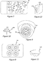
- Figures 7 - 12 illustrate additional examples of multi-image capturing devices with haptic effects in accordance with the present patent document.
- Figure 7 illustrates an example of a haptic enabled device 700 in the form of a mobile phone that incorporates seventeen image capturing devices 704; the images from the image capturing devices can be combined to form a single image from which to base image adjustments/events and corresponding haptic effects, or can be combined to produce a plurality of combined images from the various image capturing devices 704 from which to base image adjustments/events and corresponding haptic effects, or be maintained as individual images corresponding to each of the image capturing devices 704 from which to based image adjustments/events and corresponding haptic effects.
- Figure 8 illustrates an example of ceiling or wall-mounted, swiveling haptic enabled device 800 in the form of a security camera having a plurality of image capturing devices 804.
- Figure 9 illustrates an example of a haptic enabled device 900 in the form of a portable camera having four image capturing device 904.
- Figure 10 illustrates an example of a haptic enabled device 1000 with a plurality of image capturing device 1004 that can be used to generate, for example, a 360 degree image.
- Figure 11 illustrates an example of a haptic enabled device 1100 in the form of a wearable object, e.g. glasses, equipped with at least two image capturing devices 1104.
- Figure 12 illustrates an example of a haptic-enabled device 1200 in the form of a dedicated video recorder having at least two image capturing devices 1204.
Landscapes
- Engineering & Computer Science (AREA)
- Multimedia (AREA)
- Signal Processing (AREA)
- General Engineering & Computer Science (AREA)
- Human Computer Interaction (AREA)
- Theoretical Computer Science (AREA)
- Physics & Mathematics (AREA)
- General Physics & Mathematics (AREA)
- Studio Devices (AREA)
- User Interface Of Digital Computer (AREA)
- Indication In Cameras, And Counting Of Exposures (AREA)
- Cameras In General (AREA)
- Camera Bodies And Camera Details Or Accessories (AREA)
- Telephone Function (AREA)
Abstract
Description
- This patent document relates to haptic effects and, more particularly, to haptic enabled devices with multi-image capturing abilities.
- Multi-image capturing devices, such as digital cameras, smart phones, smart tablets, video recorders, etc., are generally able to provide a user of the device with improved images over those that could be obtained with a single-image capturing device. In certain configurations, the multi-image capturing devices include two lenses and two corresponding image sensors wherein each of the lenses has a different focal length, e.g. a wide angle lens and a zoom lens; the images captured at the image sensors are combined to generate a single image with improved sharpness of detail. In other configurations, the multi-image capturing devices include a plurality of lenses and corresponding image sensors wherein a portion of the image sensors provide color images while the other portion of the image sensors provide black and white images; the images of the various sensors can be combined to generate a single image with improved resolution. The presence of more than one lens and one image sensor provides a user of the device with the ability to adjust various options related to each lens and/or image sensor independently or in combination. However, determining when an adjustment is occurring or has occurred is not immediately ascertainable to the user. In some instances, visual notifications of adjustments can be provided on an LCD or other type of display however checking the display requires the user to take their eye off their photographic target and possibly move or otherwise disturb the image they are attempting to acquire.
- This patent document relates to haptic enabled devices with multi-image capturing abilities.
- In one aspect, the present patent document is directed to a haptic effect enabled system that includes a first image sensor, a second image sensor, a haptic output device and a processor coupled to the image sensors and haptic output device. The first image sensor generates a first digital image and the second image sensor generates a second digital image. The processor receives notification of an image event relating to the first or second digital image. The processor determines a haptic effect corresponding to the image event and applies the haptic effect with the haptic output device.
- In another aspect, the present patent document is directed to a haptic effect enabled system that includes a first image sensor, a second image sensor, a haptic output device and a processor coupled to the image sensors and the haptic output device. The processor receives notification of a first image event relating to the first digital image and a notification of a second image event relating to the second digital image. The processor determines a first haptic effect corresponding to the first image event and a second haptic effect corresponding to the second image event. The processor applies the first haptic effect with the haptic output device, applies a completion haptic effect with the haptic output device after application of the first haptic effect, and applies the second haptic effect with the haptic output device after application of the completion haptic effect.
- In still another aspect, the present patent document is directed to a method for producing a haptic effect that includes: receiving a first digital image from a first image sensor; receiving a second digital image from a second image sensor; receiving a notification of an image event relating to the first digital image or the second digital image; determining a haptic effect corresponding to the image event; and applying the haptic effect with a haptic output device.
-
-
Figure 1 is a schematic of a haptic enabled device with multi-image capturing abilities according to various embodiments disclosed herein. -
Figure 2 is a schematic of an example embodiment of an image capturing system having two image capturing devices that can be utilized by the haptic enabled device with multi-image capturing abilities ofFigure 1 . -
Figure 3 is a schematic of a haptic enabled device with multi-image capturing abilities according to various embodiments disclosed herein. -
Figure 4 is an example of a user interface that can be used to input image related events to the haptic enabled device with multi-image capturing abilities. -
Figure 5 is a flowchart illustrating a method for delivering haptic effects in a device with multi-image capturing abilities. -
Figure 6 is a flowchart illustrating a method for delivering haptic effects in a device with multi-image capturing abilities. -
Figures 7-12 illustrate example embodiments of haptic enabled devices with multi-image capturing abilities. - Various embodiments will be described in detail with reference to the drawings, wherein like reference numerals represent like parts and assemblies throughout the several views. Reference to various embodiments does not limit the scope of the claims attached hereto. Additionally, any examples set forth in this specification are not intended to be limiting and merely set forth some of the many possible embodiments for the appended claims.
- Whenever appropriate, terms used in the singular also will include the plural and vice versa. The use of "a" herein means "one or more" unless stated otherwise or where the use of "one or more" is clearly inappropriate. The use of "or" means "and/or" unless stated otherwise. The use of "comprise," "comprises," "comprising," "include," "includes," "including," "has," and "having" are interchangeable and not intended to be limiting. The term "such as" also is not intended to be limiting. For example, the term "including" shall mean "including, but not limited to."
- In general terms, this patent document relates to haptic enabled devices with multi-image capturing abilities.
- Haptic enabled devices with multi-image capturing abilities of the present patent document provide haptic feedback to a user of the device to indicate when an image event related to one or more of the images captured by image sensors of the haptic enabled device has started, is ongoing, or has completed. The image event can be initiated via input sensors activated by a user of the device or via automatic image events performed by an image processor. Different types of haptic feedback, e.g. haptic effects, can be provided for the different types of image events enabling a user of the device to sense the image event without having to consult a visual display indicating the status of such events.
- The image events, can include the starting, stopping or ongoing occurrence of a change in, for example: a white balance setting; an ISO setting; a shutter speed setting; a depth of field setting; an aperture size setting; a zooming operation; an anti-shake feature; a GPS tag feature; a flash; a photo size; a face detection feature; a filter; a metering feature; exposure compensation; a scene mode; image stitching; passive auto-focus; active auto-focus; hybrid auto-focus; switching from a first image to a second image; any other event related to the images capture or to be captured by the image sensors of the device. One or more of the image events can be applied simultaneously or discretely to one or more of the image capturing devices; different image events can be applied to different image capturing devices. In certain example embodiments, all pertinent image events are applied to one image capturing device before image events are applied to another image capturing device.
- Referring to
FIG. 1 , an example of a haptic enableddevice 100 with image capturing abilities is illustrated. Thedevice 100 includes ahousing 102, at least two image capturingdevices 104, anactuator 112 and acontroller 114. In various embodiments, thedevice 100 can additionally include aninput sensor 116. In general terms, thecontroller 114 operates to receive inputs from, or data related to, theimage capturing devices 104 or theinput sensor 116, and operates to generate one or more outputs based on the received inputs or data. At least one of the outputs from the controller instructs theactuator 112 to deliver a haptic effect at thehousing 102. The haptic effect can be any type of tactile sensation delivered directly or indirectly to a user. The haptic effect embodies a message such as a cue, notification, or more complex information. - The haptic enabled
device 100 can comprise, for example: a smart phone, tablet, laptop computer, desktop computer, gaming system, television, monitor, still picture camera, video camera, combination still and video camera, or any other device with at least two image capturingdevices 104. - Referring to
Figure 2 , each of the at least two image capturingdevices 104 includes alens 106 and animage sensor 108, and can additionally include a lens driver/actuator 110. - Each
lens 106 can comprise, for example, a lens of fixed focal length, a lens of variable focal length such as a zoom lens, a lens with a fixed aperture, a lens with an adjustable aperture, a prism, a mirror or any other type of device that is capable of focusing light onto theimage sensor 108. Further, eachlens 106 can comprise a single lens or a plurality of lenses, e.g. a lens assembly, to direct light to one ormore image sensors 108. In various example embodiments, one of the at least two image capturingdevices 104 uses alens 106 of a first type while another of the at least two image capturingdevices 104 uses alens 106 of a different type while in other embodiments the at least two image capturingdevices 104 use the same type oflens 106. Selection of the lens type can be based on the resultant image type desired, for example, a three-dimensional image, a stereoscopic image, or a two-dimensional image. - Each
image sensor 108 generally comprises a light detector, for example, a charge-coupled device (CCD), complementary metal-oxide-semiconductor (CMOS) image sensor, or any other device that is capable of capturing incoming light rays and converting them into electrical signals; the light can be visible light or non-visible light, e.g. infra-red light. Eachimage sensor 108 can comprise a single image sensor or a plurality of image sensors that operate to detect the light from one ormore lenses 106. Eachimage sensor 108 produces one or more outputs that are communicated to thecontroller 114; the outputs are used to generate the digital image captured by theimage sensor 108. In various example embodiments, the outputs of theimage sensors 108 are provided to animage processor 113 for generation of the image. Theimage processor 113 can be a physical processor separate from, but in communication with, thecontroller 114, a physical component incorporated into thecontroller 114, or a software module (seeimage processing module 330 ofFigure 3 ) of thecontroller 114. Theimage processor 113 can be configured to combine the outputs of theimage sensors 108 to generate the type of resultant image desired or can maintain the outputs of each of theimage sensors 108 as a separate image. - Each lens driver/
actuator 110 can be any device or combination of devices that operate to control movement of thelens 106. For example, the lens/driver actuator 110 can comprise a voice coil motor (VCM), a piezoelectric motor, a stepper motor, or micro-electro-mechanical-system (MEMS) technology. Each lens driver/actuator 110 operates under direction of thecontroller 114. - The
actuator 112 can be any controlled mechanism or other structure that initiates movement for delivery of a haptic effect. The haptic effect can be any type of tactile sensation delivered from thedevice 100 to the user. Examples ofactuators 112 include mechanisms such as motors, linear actuators (e.g. solenoids), magnetic or electromagnetic mechanisms. Additional examples ofactuators 112 include smart materials such as shape memory alloys, piezoelectric materials, electroactive polymers, and materials containing smart fluids. Theactuator 112 can comprise a single actuator or a plurality of actuators provided within thedevice 100. In the instance of a plurality ofactuators 112, the actuators can be provided in an actuator array, or individually positioned, with theactuators 112 equidistantly spaced or non-equidistantly spaced; the plurality of actuators can operate simultaneously or individually to deliver the same or different haptic effects. The haptic effect can, for example, be delivered as a vibrotactile haptic effect, an electrostatic friction (ESF) haptic effect, or a deformation haptic effect. Theactuator 112 operates under direction of thecontroller 114. - The
controller 114 is any type of circuit that controls operation of theactuator 111 based on inputs or data received at thecontroller 114 in relation to the images captured by the image-sensors 108. Data can be any type of parameters (e.g., conditions or events), instructions, flags, or other information that is processed by the processors, program modules and other hardware disclosed herein. - The
input sensor 116 can be any instrument or other device that outputs a signal in response to receiving a stimulus; theinput sensor 116 can be used to detect or sense a variety of different conditions or events. Theinput sensor 116 can be hardwired to thecontroller 114 or can be connected to the controller wirelessly. Further, theinput sensor 116 can comprise a single sensor or a plurality of sensors that are included within, or external to, thedevice 100. In various example embodiments, theinput sensor 116 can comprise a touch sensor (e.g., capacitive sensors, force-sensitive resistors, strain gauges, piezoelectric sensors, etc.) that lies behind a surface of thedevice 100. The surfaces of theelectronic device 100 can include, for example, the surfaces of a device housing, the surfaces of a device touchscreen, the surfaces of a device display screen, or the surfaces of a device button or switch. - Various other examples of
input sensors 116 include acoustical or sound sensors such as microphones; vibration sensors; electrical and magnetic sensors such as voltage detectors or hall-effect sensors; flow sensors; navigational sensors or instruments such as GPS receivers, altimeters, gyroscopes, or accelerometers; position, proximity, and movement-related sensors such as piezoelectric materials, rangefinders, odometers, speedometers, shock detectors; imaging and other optical sensors such as charge-coupled devices (CCD), CMOS sensors, infrared sensors, and photodetectors; pressure sensors such as barometers, piezometers, and tactile sensors; temperature and heat sensors such as thermometers, calorimeters, thermistors, thermocouples, and pyrometers; proximity and presence sensors such as motion detectors, triangulation sensors, radars, photo cells, sonars, and hall-effect sensors; biochips; biometric sensors such as blood pressure sensors, pulse/ox sensors, blood glucose sensors, and heart monitors. Additionally, the sensors can be formed with smart materials, such as piezo-electric polymers, which in some embodiments function as both a sensor and an actuator. - In operation of the haptic
enabled device 100 with multi-image capturing abilities, an image event occurs, viainput sensor 116 orimage processor 113, relating to one or more of the images generated from the outputs of theimage sensors 108 of theimage capturing devices 104. The generated images are digital images that can exist in a visual form, e.g. presented on a display of thedevice 100, or in a non-visual form, e.g., represented by bits in a memory of thedevice 100. The image events that occur can be related to a single image that reflects the combining of images from each of theimage sensors 108, to multiple images that reflect different combinations of the various images from theimage sensors 108, or to individual images corresponding to each of theimage sensors 108. Thecontroller 114 responds to the image event by determining a haptic effect associated with the image event and by directing theactuator 112 to apply the associated haptic effect at the hapticenabled device 100 to notify the user of the hapticenabled device 100 that an image event is occurring or has occurred. -
Figure 3 illustrates a more detailed schematic of an example embodiment of a hapticenabled device 300 with multi-image capturing abilities. Similar to the embodiment ofFigure 1 thedevice 300 includes ahousing 102, at least twoimage capturing devices 104, anactuator 112, acontroller 114 and aninput sensor 116; one or moreactuator drive circuits 318 are also included. The one or moreactuator drive circuits 318 are circuits that receive a haptic signal from thecontroller 114. The haptic signal embodies haptic data, and the haptic data defines parameters that theactuator drive circuit 318 uses to generate a haptic drive signal. Examples of parameters that can be defined by the haptic data include frequency, amplitude, phase, inversion, duration, waveform, attack time, rise time, fade time, and lag or lead time relative to an event. The haptic drive signal is applied to the one ormore actuators 112 causing motion within theactuators 112. - The
controller 114 generally includes a bus 320, aprocessor 322, an input/output (I/O)controller 324 and amemory 326. The bus 320 couples the various components of thecontroller 114, including the I/O controller 324 andmemory 326, to theprocessor 322. The bus 320 typically comprises a control bus, address bus, and data bus. However, the bus 320 can be any bus or combination of buses suitable to transfer data between components in thecontroller 114. - The
processor 322 can comprise any circuit configured to process information and can include a suitable analog or digital circuit. Theprocessor 322 can also include a programmable circuit that executes instructions. Examples of programmable circuits include microprocessors, microcontrollers, application specific integrated circuits (ASICs), programmable gate arrays (PGAs), field programmable gate arrays (FPGAs), or any other processor or hardware suitable for executing instructions. In the various embodiments theprocessor 322 can comprise a single unit, or a combination of two or more units, with the units physically located in asingle controller 114 or in separate devices. - The I/
O controller 324 comprises circuitry that monitors the operation of thecontroller 114, and peripheral or external devices such as theimage capturing devices 104, theinput sensor 116 and theactuator drive circuit 318. The I/O controller 324 further manages data flow between thecontroller 114 and the peripheral devices, and frees theprocessor 322 from details associated with monitoring and controlling the peripheral devices. Examples of other peripheral orexternal devices 328 with which the I/O controller 324 can interface include external storage devices, monitors, input devices such as keyboards, mice or pushbuttons, external computing devices, mobile devices, and transmitters/receivers. - The
memory 326 can comprise volatile memory such as random access memory (RAM), read only memory (ROM), electrically erasable programmable read only memory (EERPOM), flash memory, magnetic memory, optical memory or any other suitable memory technology. Thememory 326 can also comprise a combination of volatile and nonvolatile memory. - The
memory 326 stores a number of program modules for execution by theprocessor 322, including animage processing module 330, anevent detection module 332, and aneffect determination module 334. Each program module is a collection of data, routines, objects, calls and other instructions that perform one or more particular task. Although certain program modules are disclosed herein, the various instructions and tasks described for each module can, in various embodiments, be performed by a single program module, a different combination of modules, modules other than those disclosed herein, or modules executed by remote devices that are in communication with thecontroller 114. - The
image processing module 330 is programmed to receive input data from theinput sensor 116, image data from theimage sensors 108, inputs from any other sources or sensors (located internally or externally to the device 300) in communication with thedevice 300, inputs from any of the various program modules of thedevice 300 or any combination thereof. Theimage processing module 330 generates images from the image data and executes image events related to the images (before or after the image is generated) based on the input data from theinput sensors 116, input from the other sources or sensors, or inputs from the various program modules (e.g. programmed automatic operations). The image events can be executed prior to an image store-to-memory operation of thedevice 300 or after an image store-to-memory operation of thedevice 300. - The image events, can include the starting, stopping or ongoing occurrence of a change in:
- (a) a white balance setting (e.g. a color balance to make an image warmer or cooler) of the
device - (b) an ISO setting (e.g. sensitivity of the
sensors 108 to light) of thedevice - (c) a shutter speed setting (e.g., the time for which a shutter is open) of the
device - (d) a depth of field setting (e.g. the distance between the closest and furthest point in an image that are in acceptable focus; shorter depth of field - small amount of image in focus; larger depth of field - larger amount of image in focus) of the
device - (e) an aperture size setting (e.g. f-stop setting);
- (f) a zooming operation (e.g., zooming-in a lens reduces the quality of the image due to the reduction in the number of pixels utilized by the
image sensor 108 from which the image will be generated; zooming-out of the lens increases quality of the image due to additional pixels being used by theimage sensor 108.) of thedevice - (g) an anti-shake feature of the
device - (h) a GPS tag feature of the
device - (i) a flash of the
device - (j) a photo size generated by the
device - (k) a face detection feature of the
device - (l) a filter of the
device - (m) a metering feature (e.g. measuring the brightness of the subject of the image) of the
device - (n) exposure compensation (e.g., making the image brighter or darker) of the
device - (o) a scene or scene mode (e.g. pre-set exposure mode) of the
device - (p) applying a template to an image captured by the
device - (q) a timer of the
device - (r) image stitching/photo stitching of overlapping images to create a panoramic image with the
device - (s) performance of passive auto-focus using phase detection (PD) or performance of passive auto-focusing using contrast detection by the
device - (t) performance of active auto-focus by the
device - (u) performance of hybrid (e.g. combination of passive and active) auto-focus by the by the
device - (v) switching from performing image events related to a first image captured by one by the
image sensors 108 to performing image events related to a second image captured by another of theimage sensors 108; or - (w) any other event related to the images captured or to be captured by the
image sensors 108 of thedevice - In certain examples, the image events can include the approaching, meeting, or receding from a threshold value or measurement by the
device device image sensors 108 and analyzed by theimage processing module 330 using triangulation to determine to determine the objects' distance from the camera; the determination of the distance is used to trigger a haptic effect. In the instance of adevice more image sensors 108 detects a scene under its own ambient light illumination while phase detection or contrast detection schemes are used to determine an objects distance within the scene; the determination of the distance is used to trigger a haptic effect. Theimage processing module 330 can include processing algorithms to identify a spot on the image sensor(s) 108 corresponding to particular targets within an image to focus or blur (e.g. identifying a face and focusing the pixels corresponding to the face). When a level or threshold of focusing or blurring is achieved a haptic effect is triggered. -
Figure 4 , provides an example of auser interface 400 usable withdevice Figures 1 and3 ). A user of thedevice user interface 400 image events for each of the at least two image-capturingdevices 104, which in this example, are identified as "Camera 1" and "Camera 2." Theuser interface 400 provides each of "Camera 1" and "Camera 2" with aslidable scale 402 adjustment for white balance, aslidable scale 404 adjustment for ISO setting (e.g., an adjustment of the light sensitivity of the image sensor 108), aslidable scale 406 adjustment for shutter speed, and aslidable scale 408 adjustment for focus, or focal length. Alternatively, the user may select the "AUTO"icon 410 enabling thedevice 300 to automatically set each of the noted adjustments and/or other image events affecting an image. - While the example of
Figure 4 illustrates slidable scales as the interface for user input, other user interfaces such as a keyboard for data entry, push buttons, selectors, or any other type of interface enabling user input to thedevice user interface 400 to additionally or alternatively include options for the various other image events noted herein. - Referring once again to
Figure 3 , the inputs for the image events are received at thecontroller 114. Thecontroller 114 responds by directing thelens drivers 110, theimage sensors 108 and/or any other component/module having the ability to apply the image events, to perform their designated function. The start, ongoing occurrence, or completion of each image event, based on user input or automatic operation of thedevice 300 can be deemed a haptic event for which haptic event data can be generated by theimage processing module 330. - The
event detection module 332 is programmed to receive image event data from theimage processing module 330 and evaluate the received image event data to determine if the image event data is associated with a haptic effect. Upon theevent detection module 332 determining that the image event data is associated with a haptic effect, theeffect determination module 334 selects a haptic effect to deliver through theactuator 112. An example technique that theeffect determination module 334 can use to select a haptic effect includes rules programmed to make decisions on the selection of a haptic effect. Another example technique that can be used by theeffect determination module 334 to select a haptic effect includes lookup tables or databases that relate the haptic effect to the event data. - Upon selection of the haptic effect, the
controller 114 generates a haptic instruction signal to theactuator drive circuit 318 to direct activation of the one ormore actuators 112 to deliver the haptic effect at thedevice actuator drive circuit 318 generates a corresponding actuator drive signal that is delivered to theactuator 112 causing actuator operation. - As noted herein, the haptic instruction signal embodies haptic data, and the haptic data defines parameters that the
actuator drive circuit 318 uses to generate a haptic drive signal. Examples of parameters that can be defined by the haptic data include frequency, amplitude, phase, inversion, duration, waveform, attack time, rise time, fade time, and lag or lead time relative to an event. The haptic drive signal is applied to the one ormore actuators 112 causing motion within theactuators 112 thereby delivering to the user of the device a haptic effect. The delivery of the haptic effect can be configured to be delivered simultaneously to, prior to, or after the image adjustment made by thedevice 300 to represent, for example, an ongoing image adjustment, a start of an image adjustment or the completion of an image adjustment; different haptic effects can be used to indicate different adjustments. -
Figure 5 provides a flowchart illustrating asimplified method 500 of operation for a haptic enabled device with multi-image capturing abilities. Themethod 500 can be utilized with any of the various embodiments or combination of embodiments described herein. Themethod 500 includes: receiving notification of an image event related to any one or more of the images captured by the at least two image capturing device, S502; determining the haptic effect stored in memory that corresponds to the image event and issuing an instruction to deliver the haptic effect, S504; optionally, issuing an instruction to deliver a haptic effect when the device transitions from applying image events related to one of the at least two image capturing devices to applying image events to another of the at least two image capturing devices, S506; and delivering the haptic effect(s) at the housing of the device, S508. -
Figure 6 provides a more detailed flowchart illustrating anexample method 600 of operation for a haptic enabled device with multi-image capturing abilities. Themethod 600 can be utilized with any of the various embodiments or combination of embodiments described herein. Themethod 600 is described with reference to a haptic enabled device that includes two image capturing devices but can be expanded to include a further number of image capturing devices. Themethod 600 begins with determining whether user wishes to manually adjust the one or more images they have obtained with the multi-image capturing device; each manual adjustment is an image event. If the user does not wish to adjust the one or more images (S602:NO), themethod 600 ends, S604. However, if the user does wish to adjust the one or more images obtained with the multi-image capturing device (S602:YES), the user is provided with the option to make image adjustments affecting the image captured or to be captured by the first image capturing device, S606. - If the user chooses to make image adjustments affecting the image captured by the first image capturing device (S606:YES), the user may then choose to adjust the white balance of the image by entering a desired adjustment through an input sensor of the device (S608:YES) or choose not to enter a white balance adjustment (S608:NO). The user can further choose to adjust the ISO setting of the image by entering a desired adjustment through an input sensor of the device (S610:YES) or choose not enter an ISO setting adjustment (S610:NO). The user can also choose to adjust the shutter speed in relation to the image by entering a shutter speed adjustment through an input sensor (S612:YES) or choose not to adjust the shutter speed (S612:NO). The user can choose to adjust the focus of the image by entering a focus adjustment through an input sensor (S614:YES) or choose not to adjust the focus (S614:NO). The user can opt to apply any other an image event that affects the image by entering a desired adjustment, parameter, setting, etc. (S616:YES) or choose not to apply any other image event (S616:NO). If any image event(s) are desired by the user, the image events are provided to the
haptic effect sub-method 650, described further below. If no image events are desired, the method returns to choosing whether to manually adjust the image, S602. - If the user chooses not to apply image events to the image captured by the first image capturing device (S606:NO), the user may choose to apply image adjustments/events to the image captured by the second image capturing device, S618. If the user chooses not to apply image adjustments/events (S618:NO), the
method 600 ends. If the user does choose to make manual image adjustments to the image captured by the second image capturing device (S618:YES), the user may then choose to adjust the white balance of the image by entering a desired adjustment through an input sensor of the device (S620:YES) or choose not to enter a white balance adjustment (S620:NO). The user can further choose to adjust the ISO setting of the image by entering a desired adjustment through an input sensor of the device (S622:YES) or choose not enter an ISO setting adjustment (S622:NO). The user can also choose to adjust the shutter speed in relation to the image by entering a shutter speed adjustment through an input sensor (S624:YES) or choose not to adjust the shutter speed (S624:NO). The user can choose to adjust the focus of the image by entering a focus adjustment through an input sensor (S626:YES) or choose not to adjust the focus (S626:NO). The user can opt to apply any other image event that affects the image by entering a desired adjustment, parameter, setting, etc. through an input sensor (S628:YES) or choose not to apply an image event (S628:NO). If any image events are desired by the user, the image events are provided to thehaptic effect sub-method 650, described further below. If no image events are applied, the method returns to choosing whether to manually adjust the image, S602. - The
haptic effect sub-method 650 operates to receive, S652, each of the image events and determines whether there is a haptic effect stored in memory corresponding to the received image event, S654. If there is no corresponding haptic effect (S654:NO), the haptic effect sub-method ends, S656. If there is a haptic effect stored in memory that corresponds to the image event (S654:YES), the corresponding haptic effect is selected, S658, and a haptic instruction signal for the selected haptic effect is generated, S660. The haptic instruction signal is then provided to a drive circuit, S662, to produce a drive signal to drive operation of an actuator to deliver the selected haptic effect, S664. Operation of thehaptic effect sub-method 650 ends (S656) upon delivery of the haptic effect. - The steps of the
method 600 can be performed in any appropriate order to achieve the final result of the delivery of the appropriate haptic effect. The differing haptic effects for the various image adjustments can be delivered through the same or different actuators, and can further be delivered in a simultaneous delivery manner, an overlapping delivery manner, or a distinct (e.g. one haptic effect at a time), delivery manner. The above example illustrates user inputs as the impetus for the haptic effects, however, it should be noted that automatic operation of the multi-image capturing device can also result in the delivery of haptic effects based on each image adjustment that is automatically made, for example, by an image processor. - Consider an example of a haptic enabled device with multi-image capturing abilities, wherein the device comprises a mobile smart device, e.g. tablet or phone, which incorporates a two camera system (e.g., two image capturing devices 104). The two camera system includes a wide-angle first lens with an associated image sensor, and an optical zoom second lens with an associated image sensor. The software of the mobile smart device provides a user interface whereby a user can adjust the zoom of the second lens. As the controller of the mobile smart device operates to zoom the second lens according to a user's input, the controller utilizes the image generated by one or both (e.g. combined images) of the image sensors to track the zoom while also generating an instruction to deliver a haptic corresponding to the zoom operation. For example, while zooming, a haptic effect pattern is played continuously. The haptic effect strength is correlated to the zoom position or to the quality of the image. Once the desired zoom of the second lens is completed, the controller instructs the delivery of another haptic effect, e.g., a snap-in effect, indicating the zoom is complete. Accordingly, instead of using superimposed user interface elements on top of the camera's captured image to provide information feedback about adjustments to the cameras and/or their images, dynamic haptic effects, e.g. haptic feedback, is provided to indicate the occurrence and/or completion of such an adjustment.
-
Figures 7 - 12 illustrate additional examples of multi-image capturing devices with haptic effects in accordance with the present patent document.Figure 7 illustrates an example of a hapticenabled device 700 in the form of a mobile phone that incorporates seventeenimage capturing devices 704; the images from the image capturing devices can be combined to form a single image from which to base image adjustments/events and corresponding haptic effects, or can be combined to produce a plurality of combined images from the variousimage capturing devices 704 from which to base image adjustments/events and corresponding haptic effects, or be maintained as individual images corresponding to each of theimage capturing devices 704 from which to based image adjustments/events and corresponding haptic effects. -
Figure 8 illustrates an example of ceiling or wall-mounted, swiveling hapticenabled device 800 in the form of a security camera having a plurality ofimage capturing devices 804.Figure 9 illustrates an example of a hapticenabled device 900 in the form of a portable camera having fourimage capturing device 904.Figure 10 illustrates an example of a hapticenabled device 1000 with a plurality ofimage capturing device 1004 that can be used to generate, for example, a 360 degree image.Figure 11 illustrates an example of a hapticenabled device 1100 in the form of a wearable object, e.g. glasses, equipped with at least two image capturing devices 1104.Figure 12 illustrates an example of a haptic-enableddevice 1200 in the form of a dedicated video recorder having at least twoimage capturing devices 1204. - The various embodiments described above are provided by way of illustration only and should not be construed to limit the claims attached hereto. Those skilled in the art will readily recognize various modifications and changes that may be made without following the example embodiments and applications illustrated and described herein, and without departing from the true spirit and scope of the following claims. For example, various embodiments and their operations can be applicable to haptic enabled device having only a single image capturing device.
Claims (15)
- A haptic effect enabled system comprising:a first image sensor that generates a first digital image;a second image sensor that generates a second digital image;a haptic output device;a processor coupled to the first and second image sensors and to the haptic output device, wherein the processor:receives notification of at least one image event relating to the first digital image and/or the second digital image;determines at least one haptic effect corresponding to the at least one image event; andapplies the at least one haptic effect with the haptic output device.
- The system of claim 1, wherein the first image sensor is associated with a first image capturing device having a first lens and wherein the second image sensor is associated with a second image capturing device having a second lens.
- The system of claim 2, wherein a lens type of the first and second lens comprise a wide angle lens or a zoom lens; or
wherein the lens type of the first lens comprises a wide angle lens and wherein the lens type of the second lens comprises a zoom lens. - The system of any one of claims 1 to 3, wherein the processor receives notification of a plurality of image events relating to the first digital image and/or the second digital image, and
wherein the processor determines that the haptic effect corresponding to one of the plurality of image events is different from the haptic effect corresponding to another of the plurality of haptic events. - The system of any one of claims 1 to 4, wherein the processor receives notification of a plurality of image events, wherein at least one of the plurality of image events relates to the first digital image and wherein at least another of the plurality of image events relates to the second digital image.
- The system of claim 5, wherein the processor determines the haptic effect corresponding to the at least one of the plurality of image events and determines the haptic effect corresponding to the at least another of the plurality of image events, wherein the haptic effect corresponding to the at least one or the plurality of image events and the haptic effect corresponding to the at least another of the plurality of image events are applied at different times; or
wherein the processor determines the haptic effect corresponding to the at least one of the plurality of image events and determines the haptic effect corresponding to the at least another of the plurality of image events, wherein the haptic effect corresponding to the at least one or the plurality of image events and the haptic effect corresponding to the at least another of the plurality of image events are applied at the same time using at least two haptic output devices. - The system of any one of claims 1 to 6, wherein the image event comprises a change in white balance, a change in an ISO (International Standards Organization) setting, a change in a shutter speed setting or a change in a depth of field setting; and/or
wherein the image event comprises: an aperture size adjustment; a zooming operation; an anti-shake operation; a GPS tag operation; a flash operation; a photo size adjustment; a face detection operation; a filter operation; a metering operation; an exposure compensation operation; a scene mode operation; an image stitching operation; a passive auto-focus operation; an active auto-focus operation; a hybrid auto-focus operation. - The system of any one of claims 1 to 7, wherein the processor:receives notification of a first image event relating to the first digital image;receives notification of a second image even relating to the second digital image;determines a first haptic effect corresponding to the first image event;determines a second haptic effect corresponding to the second image event; andapplies the first haptic effect with the haptic output device;applies a completion haptic effect with the haptic output device after application of the first haptic effect;applies the second haptic effect with the haptic output device after application of the completion haptic effect.
- The system of claim 8, wherein the same haptic output device applies each of the first haptic effect, the completion haptic effect and the second haptic effect.
- The system of claim 8 or 9, wherein the haptic output device comprises at least two haptic output devices, and wherein one of the at least two haptic output devices delivers the first haptic effect and another of the at least two haptic output devices delivers the completion haptic effect.
- The system of any one of claims 8 to 10, wherein the first image event comprises a plurality of image events relating to the first digital image and wherein all haptic effects determined to correspond to the plurality of image events are applied with the haptic output device prior to applying the completion haptic effect with the haptic output device.
- A method of producing a haptic effect comprising:receiving a first digital image from a first image sensor;receiving a second digital image from a second image sensor;receiving a notification of an image event relating to the first digital image or the second digital image;determining a haptic effect corresponding to the image event; andapplying the haptic effect with a haptic output device.
- The method of claim 12, wherein the first image sensor is associated with a first image capturing device having a first lens and wherein the second image sensor is associated with a second image capturing device having a second lens,
wherein optionally the first lens comprises a wide-angle lens and the second lens comprises a zoom lens. - The method of claim 12 or 13, wherein the image event comprises: a change in white balance, a change in an ISO (International Standards Organization) setting, a change in a shutter speed setting or a change in a depth of field setting; and/or
wherein the image event comprises: an aperture size adjustment; a zooming operation; an anti-shake operation; a GPS tag operation; a flash operation; a photo size adjustment; a face detection operation; a filter operation; a metering operation; an exposure compensation operation; a scene mode operation; an image stitching operation; a passive auto-focus operation; an active auto-focus operation; a hybrid auto-focus operation. - The method of any one of claims 12 to 14, further comprising applying a completion haptic effect with the haptic output device after applying the haptic effect to the first or second digital image.
Applications Claiming Priority (1)
| Application Number | Priority Date | Filing Date | Title |
|---|---|---|---|
| US15/618,372 US10194078B2 (en) | 2017-06-09 | 2017-06-09 | Haptic enabled device with multi-image capturing abilities |
Publications (3)
| Publication Number | Publication Date |
|---|---|
| EP3413170A2 true EP3413170A2 (en) | 2018-12-12 |
| EP3413170A3 EP3413170A3 (en) | 2019-01-02 |
| EP3413170B1 EP3413170B1 (en) | 2020-12-09 |
Family
ID=62748682
Family Applications (1)
| Application Number | Title | Priority Date | Filing Date |
|---|---|---|---|
| EP18176473.9A Not-in-force EP3413170B1 (en) | 2017-06-09 | 2018-06-07 | Haptic enabled device with multi-image capturing abilities |
Country Status (5)
| Country | Link |
|---|---|
| US (2) | US10194078B2 (en) |
| EP (1) | EP3413170B1 (en) |
| JP (1) | JP7178804B2 (en) |
| KR (1) | KR102540100B1 (en) |
| CN (1) | CN109040578A (en) |
Families Citing this family (5)
| Publication number | Priority date | Publication date | Assignee | Title |
|---|---|---|---|---|
| JP6838994B2 (en) * | 2017-02-22 | 2021-03-03 | キヤノン株式会社 | Imaging device, control method and program of imaging device |
| US20190384399A1 (en) * | 2018-06-15 | 2019-12-19 | Immersion Corporation | Piezoelectric displacement amplification apparatus |
| WO2020031527A1 (en) * | 2018-08-10 | 2020-02-13 | ソニー株式会社 | Signal generation device, signal generation method, program, and playback device |
| CN119174187A (en) * | 2022-05-10 | 2024-12-20 | 高通股份有限公司 | Camera conversion for image capture devices with variable aperture capabilities |
| US12015856B2 (en) * | 2022-06-29 | 2024-06-18 | Qualcomm Incorporated | Image processing for aperture size transition in a variable aperture (VA) camera |
Family Cites Families (90)
| Publication number | Priority date | Publication date | Assignee | Title |
|---|---|---|---|---|
| JP3948387B2 (en) * | 2002-10-24 | 2007-07-25 | 松下電器産業株式会社 | Digital camera and mobile phone device with digital camera |
| US9948885B2 (en) | 2003-12-12 | 2018-04-17 | Kurzweil Technologies, Inc. | Virtual encounters |
| US20060284834A1 (en) | 2004-06-29 | 2006-12-21 | Sensable Technologies, Inc. | Apparatus and methods for haptic rendering using a haptic camera view |
| JP3968665B2 (en) * | 2005-03-22 | 2007-08-29 | ソニー株式会社 | Imaging apparatus, information processing apparatus, information processing method, program, and program recording medium |
| SE532236C2 (en) * | 2006-07-19 | 2009-11-17 | Scalado Ab | Method in connection with taking digital pictures |
| US9370704B2 (en) | 2006-08-21 | 2016-06-21 | Pillar Vision, Inc. | Trajectory detection and feedback system for tennis |
| JP5191115B2 (en) * | 2006-10-04 | 2013-04-24 | イーストマン コダック カンパニー | User interface device and digital camera |
| JP5016117B2 (en) | 2008-01-17 | 2012-09-05 | アーティキュレイト テクノロジーズ インコーポレーティッド | Method and apparatus for intraoral tactile feedback |
| US8300117B2 (en) * | 2008-03-28 | 2012-10-30 | Fuji Xerox Co., Ltd. | System and method for exposing video-taking heuristics at point of capture |
| KR101553842B1 (en) | 2009-04-21 | 2015-09-17 | 엘지전자 주식회사 | Portable terminal providing multi-haptic effect and control method thereof |
| US9370459B2 (en) | 2009-06-19 | 2016-06-21 | Andrew Mahoney | System and method for alerting visually impaired users of nearby objects |
| JP2011133684A (en) | 2009-12-24 | 2011-07-07 | Samsung Electronics Co Ltd | Imaging apparatus and method for transmitting quantity of state of the imaging apparatus |
| EP2369444B1 (en) * | 2010-03-01 | 2017-11-22 | BlackBerry Limited | Method of providing tactile feedback and apparatus |
| WO2011127379A2 (en) | 2010-04-09 | 2011-10-13 | University Of Florida Research Foundation Inc. | Interactive mixed reality system and uses thereof |
| US9204026B2 (en) * | 2010-11-01 | 2015-12-01 | Lg Electronics Inc. | Mobile terminal and method of controlling an image photographing therein |
| CN103621056A (en) * | 2011-06-23 | 2014-03-05 | 株式会社尼康 | Image capturing apparatus |
| JP5388238B2 (en) * | 2011-07-06 | 2014-01-15 | Necシステムテクノロジー株式会社 | Tactile display device, tactile display method, and program |
| US9462262B1 (en) | 2011-08-29 | 2016-10-04 | Amazon Technologies, Inc. | Augmented reality environment with environmental condition control |
| US10852093B2 (en) | 2012-05-22 | 2020-12-01 | Haptech, Inc. | Methods and apparatuses for haptic systems |
| US9325889B2 (en) * | 2012-06-08 | 2016-04-26 | Samsung Electronics Co., Ltd. | Continuous video capture during switch between video capture devices |
| KR101671137B1 (en) * | 2012-12-04 | 2016-10-31 | 엘지전자 주식회사 | Image capturing device and method thereof |
| FR2999741B1 (en) | 2012-12-17 | 2015-02-06 | Centre Nat Rech Scient | HAPTIC SYSTEM FOR NON-CONTACT INTERACTING AT LEAST ONE PART OF THE BODY OF A USER WITH A VIRTUAL ENVIRONMENT |
| KR20140090318A (en) | 2013-01-07 | 2014-07-17 | 삼성전자주식회사 | Supporting Method For Operating a Camera based on a Haptic function and Electronic Device supporting the same |
| US9367136B2 (en) | 2013-04-12 | 2016-06-14 | Microsoft Technology Licensing, Llc | Holographic object feedback |
| JP6157215B2 (en) | 2013-05-23 | 2017-07-05 | キヤノン株式会社 | Display control apparatus and control method thereof |
| US9908048B2 (en) | 2013-06-08 | 2018-03-06 | Sony Interactive Entertainment Inc. | Systems and methods for transitioning between transparent mode and non-transparent mode in a head mounted display |
| US9811854B2 (en) | 2013-07-02 | 2017-11-07 | John A. Lucido | 3-D immersion technology in a virtual store |
| WO2015002850A1 (en) | 2013-07-05 | 2015-01-08 | Rubin Jacob A | Whole-body human-computer interface |
| US9630105B2 (en) | 2013-09-30 | 2017-04-25 | Sony Interactive Entertainment Inc. | Camera based safety mechanisms for users of head mounted displays |
| KR101507242B1 (en) | 2013-10-21 | 2015-03-31 | 포항공과대학교 산학협력단 | Apparatus and method for providing motion haptic effect using video analysis |
| JP2015130006A (en) | 2014-01-06 | 2015-07-16 | キヤノン株式会社 | Touch control device, touch control method, and program |
| JP6289100B2 (en) | 2014-01-06 | 2018-03-07 | キヤノン株式会社 | Information processing apparatus, information processing method, and program |
| KR102153436B1 (en) * | 2014-01-15 | 2020-09-08 | 엘지전자 주식회사 | Mobile terminal and method for controlling the same |
| EP3095023A1 (en) | 2014-01-15 | 2016-11-23 | Sony Corporation | Haptic notification on wearables |
| JP2015138416A (en) | 2014-01-22 | 2015-07-30 | キヤノン株式会社 | Electronic device, control method thereof, and program |
| CN103795864B (en) * | 2014-01-29 | 2016-09-28 | 华为技术有限公司 | The system of selection of mobile terminal front camera and rear camera and mobile terminal |
| JP6381240B2 (en) | 2014-03-14 | 2018-08-29 | キヤノン株式会社 | Electronic device, tactile sensation control method, and program |
| JP6300604B2 (en) | 2014-04-01 | 2018-03-28 | キヤノン株式会社 | Touch control device, touch control method, and program |
| US9690370B2 (en) * | 2014-05-05 | 2017-06-27 | Immersion Corporation | Systems and methods for viewport-based augmented reality haptic effects |
| EP2942936B1 (en) | 2014-05-06 | 2017-12-20 | Nokia Technologies OY | Zoom input and camera selection |
| US9507420B2 (en) * | 2014-05-13 | 2016-11-29 | Qualcomm Incorporated | System and method for providing haptic feedback to assist in capturing images |
| US9551873B2 (en) | 2014-05-30 | 2017-01-24 | Sony Interactive Entertainment America Llc | Head mounted device (HMD) system having interface with mobile computing device for rendering virtual reality content |
| CN111998027B (en) | 2014-07-28 | 2022-05-27 | Ck高新材料有限公司 | Tactile information providing method |
| US9742977B2 (en) | 2014-09-02 | 2017-08-22 | Apple Inc. | Camera remote control |
| US9645646B2 (en) | 2014-09-04 | 2017-05-09 | Intel Corporation | Three dimensional contextual feedback wristband device |
| US9922236B2 (en) | 2014-09-17 | 2018-03-20 | Toyota Motor Engineering & Manufacturing North America, Inc. | Wearable eyeglasses for providing social and environmental awareness |
| US10024678B2 (en) | 2014-09-17 | 2018-07-17 | Toyota Motor Engineering & Manufacturing North America, Inc. | Wearable clip for providing social and environmental awareness |
| US9799177B2 (en) | 2014-09-23 | 2017-10-24 | Intel Corporation | Apparatus and methods for haptic covert communication |
| KR20160045269A (en) * | 2014-10-17 | 2016-04-27 | 엘지전자 주식회사 | Wearable device and mobile terminal for supporting communication with the device |
| US10166466B2 (en) | 2014-12-11 | 2019-01-01 | Elwha Llc | Feedback for enhanced situational awareness |
| US20160170508A1 (en) | 2014-12-11 | 2016-06-16 | Toyota Motor Engineering & Manufacturing North America, Inc. | Tactile display devices |
| US9870718B2 (en) | 2014-12-11 | 2018-01-16 | Toyota Motor Engineering & Manufacturing North America, Inc. | Imaging devices including spacing members and imaging devices including tactile feedback devices |
| KR20160072687A (en) | 2014-12-15 | 2016-06-23 | 삼성전기주식회사 | Camera Module |
| US9658693B2 (en) * | 2014-12-19 | 2017-05-23 | Immersion Corporation | Systems and methods for haptically-enabled interactions with objects |
| US10073516B2 (en) | 2014-12-29 | 2018-09-11 | Sony Interactive Entertainment Inc. | Methods and systems for user interaction within virtual reality scene using head mounted display |
| US9746921B2 (en) | 2014-12-31 | 2017-08-29 | Sony Interactive Entertainment Inc. | Signal generation and detector systems and methods for determining positions of fingers of a user |
| US9843744B2 (en) | 2015-01-13 | 2017-12-12 | Disney Enterprises, Inc. | Audience interaction projection system |
| US9742971B2 (en) * | 2015-02-23 | 2017-08-22 | Motorola Mobility Llc | Dual camera system zoom notification |
| US9625990B2 (en) | 2015-03-03 | 2017-04-18 | Toyota Motor Engineering & Manufacturing North America, Inc. | Vision-assist systems including user eye tracking cameras |
| US10322203B2 (en) | 2015-06-26 | 2019-06-18 | Intel Corporation | Air flow generation for scent output |
| JP6293706B2 (en) * | 2015-06-26 | 2018-03-14 | 京セラ株式会社 | Electronic device and method of operating electronic device |
| US9749543B2 (en) * | 2015-07-21 | 2017-08-29 | Lg Electronics Inc. | Mobile terminal having two cameras and method for storing images taken by two cameras |
| US9990040B2 (en) * | 2015-09-25 | 2018-06-05 | Immersion Corporation | Haptic CAPTCHA |
| US9778746B2 (en) | 2015-09-25 | 2017-10-03 | Oculus Vr, Llc | Transversal actuator for haptic feedback |
| US20170103574A1 (en) | 2015-10-13 | 2017-04-13 | Google Inc. | System and method for providing continuity between real world movement and movement in a virtual/augmented reality experience |
| JP6147829B2 (en) | 2015-10-28 | 2017-06-14 | 京セラ株式会社 | Electronic device and recording control method for electronic device |
| US20170131775A1 (en) | 2015-11-10 | 2017-05-11 | Castar, Inc. | System and method of haptic feedback by referral of sensation |
| US10055948B2 (en) | 2015-11-30 | 2018-08-21 | Nike, Inc. | Apparel with ultrasonic position sensing and haptic feedback for activities |
| US10310804B2 (en) | 2015-12-11 | 2019-06-04 | Facebook Technologies, Llc | Modifying haptic feedback provided to a user to account for changes in user perception of haptic feedback |
| US10324530B2 (en) | 2015-12-14 | 2019-06-18 | Facebook Technologies, Llc | Haptic devices that simulate rigidity of virtual objects |
| US10096163B2 (en) | 2015-12-22 | 2018-10-09 | Intel Corporation | Haptic augmented reality to reduce noxious stimuli |
| US10065124B2 (en) | 2016-01-15 | 2018-09-04 | Disney Enterprises, Inc. | Interacting with a remote participant through control of the voice of a toy device |
| US9846971B2 (en) | 2016-01-19 | 2017-12-19 | Disney Enterprises, Inc. | Systems and methods for augmenting an appearance of a hilt to simulate a bladed weapon |
| US11351472B2 (en) | 2016-01-19 | 2022-06-07 | Disney Enterprises, Inc. | Systems and methods for using a gyroscope to change the resistance of moving a virtual weapon |
| US10477006B2 (en) | 2016-01-22 | 2019-11-12 | Htc Corporation | Method, virtual reality system, and computer-readable recording medium for real-world interaction in virtual reality environment |
| US9933851B2 (en) | 2016-02-22 | 2018-04-03 | Disney Enterprises, Inc. | Systems and methods for interacting with virtual objects using sensory feedback |
| US10555153B2 (en) | 2016-03-01 | 2020-02-04 | Disney Enterprises, Inc. | Systems and methods for making non-smart objects smart for internet of things |
| KR20170112492A (en) * | 2016-03-31 | 2017-10-12 | 엘지전자 주식회사 | Mobile terminal and method for controlling the same |
| US20170352185A1 (en) | 2016-06-02 | 2017-12-07 | Dennis Rommel BONILLA ACEVEDO | System and method for facilitating a vehicle-related virtual reality and/or augmented reality presentation |
| US10701256B2 (en) * | 2016-06-12 | 2020-06-30 | Apple Inc. | Switchover control techniques for dual-sensor camera system |
| CN106066702A (en) * | 2016-08-03 | 2016-11-02 | 温州大学 | A kind of culture space analogy method based on Multimedia Digitalization technology |
| US10155159B2 (en) | 2016-08-18 | 2018-12-18 | Activision Publishing, Inc. | Tactile feedback systems and methods for augmented reality and virtual reality systems |
| US20180053351A1 (en) | 2016-08-19 | 2018-02-22 | Intel Corporation | Augmented reality experience enhancement method and apparatus |
| US10270958B2 (en) * | 2016-09-01 | 2019-04-23 | Duelight Llc | Systems and methods for adjusting focus based on focus target information |
| US10372213B2 (en) | 2016-09-20 | 2019-08-06 | Facebook Technologies, Llc | Composite ribbon in a virtual reality device |
| US10779583B2 (en) | 2016-09-20 | 2020-09-22 | Facebook Technologies, Llc | Actuated tendon pairs in a virtual reality device |
| US10300372B2 (en) | 2016-09-30 | 2019-05-28 | Disney Enterprises, Inc. | Virtual blaster |
| US10281982B2 (en) | 2016-10-17 | 2019-05-07 | Facebook Technologies, Llc | Inflatable actuators in virtual reality |
| US10088902B2 (en) | 2016-11-01 | 2018-10-02 | Oculus Vr, Llc | Fiducial rings in virtual reality |
| US20170102771A1 (en) | 2016-12-12 | 2017-04-13 | Leibs Technology Limited | Wearable ultrasonic haptic feedback system |
-
2017
- 2017-06-09 US US15/618,372 patent/US10194078B2/en active Active
-
2018
- 2018-06-05 KR KR1020180064645A patent/KR102540100B1/en active Active
- 2018-06-07 EP EP18176473.9A patent/EP3413170B1/en not_active Not-in-force
- 2018-06-08 JP JP2018110166A patent/JP7178804B2/en active Active
- 2018-06-08 CN CN201810585833.7A patent/CN109040578A/en active Pending
- 2018-12-12 US US16/218,185 patent/US20190387162A1/en not_active Abandoned
Non-Patent Citations (1)
| Title |
|---|
| None |
Also Published As
| Publication number | Publication date |
|---|---|
| KR20180134761A (en) | 2018-12-19 |
| US20180359412A1 (en) | 2018-12-13 |
| CN109040578A (en) | 2018-12-18 |
| US10194078B2 (en) | 2019-01-29 |
| JP2019003639A (en) | 2019-01-10 |
| JP7178804B2 (en) | 2022-11-28 |
| KR102540100B1 (en) | 2023-06-07 |
| EP3413170B1 (en) | 2020-12-09 |
| US20190387162A1 (en) | 2019-12-19 |
| EP3413170A3 (en) | 2019-01-02 |
Similar Documents
| Publication | Publication Date | Title |
|---|---|---|
| EP3413170B1 (en) | Haptic enabled device with multi-image capturing abilities | |
| US20060044399A1 (en) | Control system for an image capture device | |
| US8310652B2 (en) | Image taking system and lens apparatus | |
| US9967468B2 (en) | Photographing apparatus and photographing method | |
| CN103795917A (en) | Imaging apparatus and control method | |
| JP6335482B2 (en) | Imaging apparatus, control method therefor, and program | |
| EP3857864B1 (en) | Zoomed in region of interest | |
| JP2019129410A (en) | Monitoring camera, control method thereof, and program | |
| CN107637063B (en) | Method and camera for controlling functions based on user's gestures | |
| CN103533217A (en) | A camera shooting device and a camera shooting method | |
| US11812133B2 (en) | Image processing apparatus and method for controlling image processing apparatus | |
| US20160212328A1 (en) | Haptic interface of image photographing device and control method thereof | |
| US11095824B2 (en) | Imaging apparatus, and control method and control program therefor | |
| US7265790B2 (en) | System and method for setting an image capture device to an operational mode | |
| JP2013061584A (en) | Optical instrument | |
| JP2008236799A5 (en) | ||
| JP7592395B2 (en) | Focus adjustment device, imaging device, and focus adjustment method | |
| JP6851172B2 (en) | Imaging device and its control method | |
| JP6679430B2 (en) | IMAGING DEVICE, IMAGING DEVICE CONTROL METHOD, AND PROGRAM | |
| JP5907856B2 (en) | Imaging device | |
| JP5938268B2 (en) | Imaging apparatus and control method thereof | |
| JP7532060B2 (en) | Display device and control method for display device | |
| KR101284010B1 (en) | Camera equipped with rotatable lens | |
| JP2023062381A (en) | IMAGING DEVICE, CONTROL METHOD AND PROGRAM THEREOF | |
| JP6331469B2 (en) | Imaging device |
Legal Events
| Date | Code | Title | Description |
|---|---|---|---|
| PUAI | Public reference made under article 153(3) epc to a published international application that has entered the european phase |
Free format text: ORIGINAL CODE: 0009012 |
|
| STAA | Information on the status of an ep patent application or granted ep patent |
Free format text: STATUS: THE APPLICATION HAS BEEN PUBLISHED |
|
| PUAL | Search report despatched |
Free format text: ORIGINAL CODE: 0009013 |
|
| AK | Designated contracting states |
Kind code of ref document: A2 Designated state(s): AL AT BE BG CH CY CZ DE DK EE ES FI FR GB GR HR HU IE IS IT LI LT LU LV MC MK MT NL NO PL PT RO RS SE SI SK SM TR |
|
| AX | Request for extension of the european patent |
Extension state: BA ME |
|
| AK | Designated contracting states |
Kind code of ref document: A3 Designated state(s): AL AT BE BG CH CY CZ DE DK EE ES FI FR GB GR HR HU IE IS IT LI LT LU LV MC MK MT NL NO PL PT RO RS SE SI SK SM TR |
|
| AX | Request for extension of the european patent |
Extension state: BA ME |
|
| RIC1 | Information provided on ipc code assigned before grant |
Ipc: H04N 13/239 20180101ALI20181126BHEP Ipc: H04N 5/225 20060101ALI20181126BHEP Ipc: G06F 3/01 20060101AFI20181126BHEP |
|
| STAA | Information on the status of an ep patent application or granted ep patent |
Free format text: STATUS: REQUEST FOR EXAMINATION WAS MADE |
|
| 17P | Request for examination filed |
Effective date: 20190701 |
|
| RBV | Designated contracting states (corrected) |
Designated state(s): AL AT BE BG CH CY CZ DE DK EE ES FI FR GB GR HR HU IE IS IT LI LT LU LV MC MK MT NL NO PL PT RO RS SE SI SK SM TR |
|
| STAA | Information on the status of an ep patent application or granted ep patent |
Free format text: STATUS: EXAMINATION IS IN PROGRESS |
|
| 17Q | First examination report despatched |
Effective date: 20191008 |
|
| GRAP | Despatch of communication of intention to grant a patent |
Free format text: ORIGINAL CODE: EPIDOSNIGR1 |
|
| STAA | Information on the status of an ep patent application or granted ep patent |
Free format text: STATUS: GRANT OF PATENT IS INTENDED |
|
| RIC1 | Information provided on ipc code assigned before grant |
Ipc: H04N 5/225 20060101ALI20200528BHEP Ipc: H04N 13/239 20180101ALN20200528BHEP Ipc: G06F 3/01 20060101AFI20200528BHEP |
|
| INTG | Intention to grant announced |
Effective date: 20200624 |
|
| GRAS | Grant fee paid |
Free format text: ORIGINAL CODE: EPIDOSNIGR3 |
|
| GRAA | (expected) grant |
Free format text: ORIGINAL CODE: 0009210 |
|
| STAA | Information on the status of an ep patent application or granted ep patent |
Free format text: STATUS: THE PATENT HAS BEEN GRANTED |
|
| AK | Designated contracting states |
Kind code of ref document: B1 Designated state(s): AL AT BE BG CH CY CZ DE DK EE ES FI FR GB GR HR HU IE IS IT LI LT LU LV MC MK MT NL NO PL PT RO RS SE SI SK SM TR |
|
| REG | Reference to a national code |
Ref country code: GB Ref legal event code: FG4D |
|
| REG | Reference to a national code |
Ref country code: AT Ref legal event code: REF Ref document number: 1344085 Country of ref document: AT Kind code of ref document: T Effective date: 20201215 Ref country code: CH Ref legal event code: EP |
|
| REG | Reference to a national code |
Ref country code: DE Ref legal event code: R096 Ref document number: 602018010548 Country of ref document: DE |
|
| REG | Reference to a national code |
Ref country code: IE Ref legal event code: FG4D |
|
| PG25 | Lapsed in a contracting state [announced via postgrant information from national office to epo] |
Ref country code: RS Free format text: LAPSE BECAUSE OF FAILURE TO SUBMIT A TRANSLATION OF THE DESCRIPTION OR TO PAY THE FEE WITHIN THE PRESCRIBED TIME-LIMIT Effective date: 20201209 Ref country code: FI Free format text: LAPSE BECAUSE OF FAILURE TO SUBMIT A TRANSLATION OF THE DESCRIPTION OR TO PAY THE FEE WITHIN THE PRESCRIBED TIME-LIMIT Effective date: 20201209 Ref country code: NO Free format text: LAPSE BECAUSE OF FAILURE TO SUBMIT A TRANSLATION OF THE DESCRIPTION OR TO PAY THE FEE WITHIN THE PRESCRIBED TIME-LIMIT Effective date: 20210309 Ref country code: GR Free format text: LAPSE BECAUSE OF FAILURE TO SUBMIT A TRANSLATION OF THE DESCRIPTION OR TO PAY THE FEE WITHIN THE PRESCRIBED TIME-LIMIT Effective date: 20210310 |
|
| REG | Reference to a national code |
Ref country code: AT Ref legal event code: MK05 Ref document number: 1344085 Country of ref document: AT Kind code of ref document: T Effective date: 20201209 |
|
| PG25 | Lapsed in a contracting state [announced via postgrant information from national office to epo] |
Ref country code: BG Free format text: LAPSE BECAUSE OF FAILURE TO SUBMIT A TRANSLATION OF THE DESCRIPTION OR TO PAY THE FEE WITHIN THE PRESCRIBED TIME-LIMIT Effective date: 20210309 Ref country code: LV Free format text: LAPSE BECAUSE OF FAILURE TO SUBMIT A TRANSLATION OF THE DESCRIPTION OR TO PAY THE FEE WITHIN THE PRESCRIBED TIME-LIMIT Effective date: 20201209 Ref country code: SE Free format text: LAPSE BECAUSE OF FAILURE TO SUBMIT A TRANSLATION OF THE DESCRIPTION OR TO PAY THE FEE WITHIN THE PRESCRIBED TIME-LIMIT Effective date: 20201209 |
|
| REG | Reference to a national code |
Ref country code: NL Ref legal event code: MP Effective date: 20201209 |
|
| PG25 | Lapsed in a contracting state [announced via postgrant information from national office to epo] |
Ref country code: NL Free format text: LAPSE BECAUSE OF FAILURE TO SUBMIT A TRANSLATION OF THE DESCRIPTION OR TO PAY THE FEE WITHIN THE PRESCRIBED TIME-LIMIT Effective date: 20201209 Ref country code: HR Free format text: LAPSE BECAUSE OF FAILURE TO SUBMIT A TRANSLATION OF THE DESCRIPTION OR TO PAY THE FEE WITHIN THE PRESCRIBED TIME-LIMIT Effective date: 20201209 |
|
| REG | Reference to a national code |
Ref country code: LT Ref legal event code: MG9D |
|
| PG25 | Lapsed in a contracting state [announced via postgrant information from national office to epo] |
Ref country code: SM Free format text: LAPSE BECAUSE OF FAILURE TO SUBMIT A TRANSLATION OF THE DESCRIPTION OR TO PAY THE FEE WITHIN THE PRESCRIBED TIME-LIMIT Effective date: 20201209 Ref country code: EE Free format text: LAPSE BECAUSE OF FAILURE TO SUBMIT A TRANSLATION OF THE DESCRIPTION OR TO PAY THE FEE WITHIN THE PRESCRIBED TIME-LIMIT Effective date: 20201209 Ref country code: CZ Free format text: LAPSE BECAUSE OF FAILURE TO SUBMIT A TRANSLATION OF THE DESCRIPTION OR TO PAY THE FEE WITHIN THE PRESCRIBED TIME-LIMIT Effective date: 20201209 Ref country code: SK Free format text: LAPSE BECAUSE OF FAILURE TO SUBMIT A TRANSLATION OF THE DESCRIPTION OR TO PAY THE FEE WITHIN THE PRESCRIBED TIME-LIMIT Effective date: 20201209 Ref country code: PT Free format text: LAPSE BECAUSE OF FAILURE TO SUBMIT A TRANSLATION OF THE DESCRIPTION OR TO PAY THE FEE WITHIN THE PRESCRIBED TIME-LIMIT Effective date: 20210409 Ref country code: RO Free format text: LAPSE BECAUSE OF FAILURE TO SUBMIT A TRANSLATION OF THE DESCRIPTION OR TO PAY THE FEE WITHIN THE PRESCRIBED TIME-LIMIT Effective date: 20201209 Ref country code: LT Free format text: LAPSE BECAUSE OF FAILURE TO SUBMIT A TRANSLATION OF THE DESCRIPTION OR TO PAY THE FEE WITHIN THE PRESCRIBED TIME-LIMIT Effective date: 20201209 |
|
| PG25 | Lapsed in a contracting state [announced via postgrant information from national office to epo] |
Ref country code: AT Free format text: LAPSE BECAUSE OF FAILURE TO SUBMIT A TRANSLATION OF THE DESCRIPTION OR TO PAY THE FEE WITHIN THE PRESCRIBED TIME-LIMIT Effective date: 20201209 Ref country code: PL Free format text: LAPSE BECAUSE OF FAILURE TO SUBMIT A TRANSLATION OF THE DESCRIPTION OR TO PAY THE FEE WITHIN THE PRESCRIBED TIME-LIMIT Effective date: 20201209 |
|
| REG | Reference to a national code |
Ref country code: DE Ref legal event code: R097 Ref document number: 602018010548 Country of ref document: DE |
|
| PG25 | Lapsed in a contracting state [announced via postgrant information from national office to epo] |
Ref country code: IS Free format text: LAPSE BECAUSE OF FAILURE TO SUBMIT A TRANSLATION OF THE DESCRIPTION OR TO PAY THE FEE WITHIN THE PRESCRIBED TIME-LIMIT Effective date: 20210409 |
|
| PLBE | No opposition filed within time limit |
Free format text: ORIGINAL CODE: 0009261 |
|
| STAA | Information on the status of an ep patent application or granted ep patent |
Free format text: STATUS: NO OPPOSITION FILED WITHIN TIME LIMIT |
|
| PG25 | Lapsed in a contracting state [announced via postgrant information from national office to epo] |
Ref country code: IT Free format text: LAPSE BECAUSE OF FAILURE TO SUBMIT A TRANSLATION OF THE DESCRIPTION OR TO PAY THE FEE WITHIN THE PRESCRIBED TIME-LIMIT Effective date: 20201209 Ref country code: AL Free format text: LAPSE BECAUSE OF FAILURE TO SUBMIT A TRANSLATION OF THE DESCRIPTION OR TO PAY THE FEE WITHIN THE PRESCRIBED TIME-LIMIT Effective date: 20201209 |
|
| 26N | No opposition filed |
Effective date: 20210910 |
|
| PG25 | Lapsed in a contracting state [announced via postgrant information from national office to epo] |
Ref country code: DK Free format text: LAPSE BECAUSE OF FAILURE TO SUBMIT A TRANSLATION OF THE DESCRIPTION OR TO PAY THE FEE WITHIN THE PRESCRIBED TIME-LIMIT Effective date: 20201209 Ref country code: SI Free format text: LAPSE BECAUSE OF FAILURE TO SUBMIT A TRANSLATION OF THE DESCRIPTION OR TO PAY THE FEE WITHIN THE PRESCRIBED TIME-LIMIT Effective date: 20201209 |
|
| PG25 | Lapsed in a contracting state [announced via postgrant information from national office to epo] |
Ref country code: MC Free format text: LAPSE BECAUSE OF FAILURE TO SUBMIT A TRANSLATION OF THE DESCRIPTION OR TO PAY THE FEE WITHIN THE PRESCRIBED TIME-LIMIT Effective date: 20201209 Ref country code: ES Free format text: LAPSE BECAUSE OF FAILURE TO SUBMIT A TRANSLATION OF THE DESCRIPTION OR TO PAY THE FEE WITHIN THE PRESCRIBED TIME-LIMIT Effective date: 20201209 |
|
| REG | Reference to a national code |
Ref country code: CH Ref legal event code: PL |
|
| REG | Reference to a national code |
Ref country code: BE Ref legal event code: MM Effective date: 20210630 |
|
| PG25 | Lapsed in a contracting state [announced via postgrant information from national office to epo] |
Ref country code: LU Free format text: LAPSE BECAUSE OF NON-PAYMENT OF DUE FEES Effective date: 20210607 |
|
| PG25 | Lapsed in a contracting state [announced via postgrant information from national office to epo] |
Ref country code: LI Free format text: LAPSE BECAUSE OF NON-PAYMENT OF DUE FEES Effective date: 20210630 Ref country code: IE Free format text: LAPSE BECAUSE OF NON-PAYMENT OF DUE FEES Effective date: 20210607 Ref country code: CH Free format text: LAPSE BECAUSE OF NON-PAYMENT OF DUE FEES Effective date: 20210630 |
|
| PG25 | Lapsed in a contracting state [announced via postgrant information from national office to epo] |
Ref country code: IS Free format text: LAPSE BECAUSE OF FAILURE TO SUBMIT A TRANSLATION OF THE DESCRIPTION OR TO PAY THE FEE WITHIN THE PRESCRIBED TIME-LIMIT Effective date: 20210409 |
|
| PG25 | Lapsed in a contracting state [announced via postgrant information from national office to epo] |
Ref country code: BE Free format text: LAPSE BECAUSE OF NON-PAYMENT OF DUE FEES Effective date: 20210630 |
|
| P01 | Opt-out of the competence of the unified patent court (upc) registered |
Effective date: 20230524 |
|
| PG25 | Lapsed in a contracting state [announced via postgrant information from national office to epo] |
Ref country code: CY Free format text: LAPSE BECAUSE OF FAILURE TO SUBMIT A TRANSLATION OF THE DESCRIPTION OR TO PAY THE FEE WITHIN THE PRESCRIBED TIME-LIMIT Effective date: 20201209 |
|
| PG25 | Lapsed in a contracting state [announced via postgrant information from national office to epo] |
Ref country code: HU Free format text: LAPSE BECAUSE OF FAILURE TO SUBMIT A TRANSLATION OF THE DESCRIPTION OR TO PAY THE FEE WITHIN THE PRESCRIBED TIME-LIMIT; INVALID AB INITIO Effective date: 20180607 |
|
| PG25 | Lapsed in a contracting state [announced via postgrant information from national office to epo] |
Ref country code: MK Free format text: LAPSE BECAUSE OF FAILURE TO SUBMIT A TRANSLATION OF THE DESCRIPTION OR TO PAY THE FEE WITHIN THE PRESCRIBED TIME-LIMIT Effective date: 20201209 |
|
| PGFP | Annual fee paid to national office [announced via postgrant information from national office to epo] |
Ref country code: GB Payment date: 20240627 Year of fee payment: 7 |
|
| PGFP | Annual fee paid to national office [announced via postgrant information from national office to epo] |
Ref country code: DE Payment date: 20240627 Year of fee payment: 7 |
|
| PGFP | Annual fee paid to national office [announced via postgrant information from national office to epo] |
Ref country code: FR Payment date: 20240625 Year of fee payment: 7 |
|
| PG25 | Lapsed in a contracting state [announced via postgrant information from national office to epo] |
Ref country code: MT Free format text: LAPSE BECAUSE OF FAILURE TO SUBMIT A TRANSLATION OF THE DESCRIPTION OR TO PAY THE FEE WITHIN THE PRESCRIBED TIME-LIMIT Effective date: 20201209 |
|
| PG25 | Lapsed in a contracting state [announced via postgrant information from national office to epo] |
Ref country code: TR Free format text: LAPSE BECAUSE OF FAILURE TO SUBMIT A TRANSLATION OF THE DESCRIPTION OR TO PAY THE FEE WITHIN THE PRESCRIBED TIME-LIMIT Effective date: 20201209 |
|
| REG | Reference to a national code |
Ref country code: DE Ref legal event code: R119 Ref document number: 602018010548 Country of ref document: DE |
|
| GBPC | Gb: european patent ceased through non-payment of renewal fee |
Effective date: 20250607 |
|
| PG25 | Lapsed in a contracting state [announced via postgrant information from national office to epo] |
Ref country code: GB Free format text: LAPSE BECAUSE OF NON-PAYMENT OF DUE FEES Effective date: 20250607 |
|
| PG25 | Lapsed in a contracting state [announced via postgrant information from national office to epo] |
Ref country code: DE Free format text: LAPSE BECAUSE OF NON-PAYMENT OF DUE FEES Effective date: 20260101 |
|
| PG25 | Lapsed in a contracting state [announced via postgrant information from national office to epo] |
Ref country code: FR Free format text: LAPSE BECAUSE OF NON-PAYMENT OF DUE FEES Effective date: 20250630 |