EP3413151A1 - Systèmes de gestion de qualité, procédés et produits-programmes de chaînes d'approvisionnement de fabrication additive - Google Patents
Systèmes de gestion de qualité, procédés et produits-programmes de chaînes d'approvisionnement de fabrication additive Download PDFInfo
- Publication number
- EP3413151A1 EP3413151A1 EP18175276.7A EP18175276A EP3413151A1 EP 3413151 A1 EP3413151 A1 EP 3413151A1 EP 18175276 A EP18175276 A EP 18175276A EP 3413151 A1 EP3413151 A1 EP 3413151A1
- Authority
- EP
- European Patent Office
- Prior art keywords
- sensor
- components
- quality management
- management system
- profiles
- Prior art date
- Legal status (The legal status is an assumption and is not a legal conclusion. Google has not performed a legal analysis and makes no representation as to the accuracy of the status listed.)
- Pending
Links
- 238000000034 method Methods 0.000 title claims abstract description 71
- 238000004519 manufacturing process Methods 0.000 title claims abstract description 63
- 239000000654 additive Substances 0.000 title claims abstract description 14
- 230000000996 additive effect Effects 0.000 title claims abstract description 12
- 238000003326 Quality management system Methods 0.000 title claims 19
- 238000013461 design Methods 0.000 claims abstract description 33
- 230000000246 remedial effect Effects 0.000 claims abstract description 27
- 230000004927 fusion Effects 0.000 claims description 22
- 230000006854 communication Effects 0.000 claims description 15
- 238000004891 communication Methods 0.000 claims description 15
- 238000003860 storage Methods 0.000 claims description 12
- 230000005540 biological transmission Effects 0.000 claims description 5
- 230000002730 additional effect Effects 0.000 claims description 3
- 230000004044 response Effects 0.000 claims description 3
- 230000008569 process Effects 0.000 abstract description 32
- 238000003908 quality control method Methods 0.000 abstract description 25
- 238000004458 analytical method Methods 0.000 description 19
- 238000012360 testing method Methods 0.000 description 18
- 230000006870 function Effects 0.000 description 14
- 239000000843 powder Substances 0.000 description 14
- 238000009529 body temperature measurement Methods 0.000 description 8
- 238000007726 management method Methods 0.000 description 7
- 239000000463 material Substances 0.000 description 7
- 239000002184 metal Substances 0.000 description 6
- 229910052751 metal Inorganic materials 0.000 description 6
- 238000010200 validation analysis Methods 0.000 description 6
- 238000005259 measurement Methods 0.000 description 5
- 238000010586 diagram Methods 0.000 description 4
- 238000000149 argon plasma sintering Methods 0.000 description 3
- 230000002708 enhancing effect Effects 0.000 description 3
- PXHVJJICTQNCMI-UHFFFAOYSA-N Nickel Chemical compound [Ni] PXHVJJICTQNCMI-UHFFFAOYSA-N 0.000 description 2
- 230000007175 bidirectional communication Effects 0.000 description 2
- 230000008021 deposition Effects 0.000 description 2
- 238000009826 distribution Methods 0.000 description 2
- 238000010894 electron beam technology Methods 0.000 description 2
- 238000010438 heat treatment Methods 0.000 description 2
- 230000015654 memory Effects 0.000 description 2
- 229910000601 superalloy Inorganic materials 0.000 description 2
- 238000010146 3D printing Methods 0.000 description 1
- 238000013459 approach Methods 0.000 description 1
- 230000002146 bilateral effect Effects 0.000 description 1
- 230000001413 cellular effect Effects 0.000 description 1
- 229910017052 cobalt Inorganic materials 0.000 description 1
- 239000010941 cobalt Substances 0.000 description 1
- GUTLYIVDDKVIGB-UHFFFAOYSA-N cobalt atom Chemical compound [Co] GUTLYIVDDKVIGB-UHFFFAOYSA-N 0.000 description 1
- 238000010835 comparative analysis Methods 0.000 description 1
- 230000000295 complement effect Effects 0.000 description 1
- 238000011960 computer-aided design Methods 0.000 description 1
- 238000007405 data analysis Methods 0.000 description 1
- 238000007689 inspection Methods 0.000 description 1
- 238000009434 installation Methods 0.000 description 1
- 239000007769 metal material Substances 0.000 description 1
- 238000012986 modification Methods 0.000 description 1
- 230000004048 modification Effects 0.000 description 1
- 238000012544 monitoring process Methods 0.000 description 1
- 229910052759 nickel Inorganic materials 0.000 description 1
- 238000007639 printing Methods 0.000 description 1
- 238000012545 processing Methods 0.000 description 1
- 230000000135 prohibitive effect Effects 0.000 description 1
- 230000001105 regulatory effect Effects 0.000 description 1
- 238000001228 spectrum Methods 0.000 description 1
- 239000007858 starting material Substances 0.000 description 1
- 230000000007 visual effect Effects 0.000 description 1
- 238000011179 visual inspection Methods 0.000 description 1
Images

Classifications
-
- G—PHYSICS
- G05—CONTROLLING; REGULATING
- G05B—CONTROL OR REGULATING SYSTEMS IN GENERAL; FUNCTIONAL ELEMENTS OF SUCH SYSTEMS; MONITORING OR TESTING ARRANGEMENTS FOR SUCH SYSTEMS OR ELEMENTS
- G05B19/00—Programme-control systems
- G05B19/02—Programme-control systems electric
- G05B19/18—Numerical control [NC], i.e. automatically operating machines, in particular machine tools, e.g. in a manufacturing environment, so as to execute positioning, movement or co-ordinated operations by means of programme data in numerical form
- G05B19/4097—Numerical control [NC], i.e. automatically operating machines, in particular machine tools, e.g. in a manufacturing environment, so as to execute positioning, movement or co-ordinated operations by means of programme data in numerical form characterised by using design data to control NC machines, e.g. CAD/CAM
- G05B19/4099—Surface or curve machining, making 3D objects, e.g. desktop manufacturing
-
- B—PERFORMING OPERATIONS; TRANSPORTING
- B29—WORKING OF PLASTICS; WORKING OF SUBSTANCES IN A PLASTIC STATE IN GENERAL
- B29C—SHAPING OR JOINING OF PLASTICS; SHAPING OF MATERIAL IN A PLASTIC STATE, NOT OTHERWISE PROVIDED FOR; AFTER-TREATMENT OF THE SHAPED PRODUCTS, e.g. REPAIRING
- B29C64/00—Additive manufacturing, i.e. manufacturing of three-dimensional [3D] objects by additive deposition, additive agglomeration or additive layering, e.g. by 3D printing, stereolithography or selective laser sintering
- B29C64/30—Auxiliary operations or equipment
- B29C64/386—Data acquisition or data processing for additive manufacturing
- B29C64/393—Data acquisition or data processing for additive manufacturing for controlling or regulating additive manufacturing processes
-
- B—PERFORMING OPERATIONS; TRANSPORTING
- B33—ADDITIVE MANUFACTURING TECHNOLOGY
- B33Y—ADDITIVE MANUFACTURING, i.e. MANUFACTURING OF THREE-DIMENSIONAL [3-D] OBJECTS BY ADDITIVE DEPOSITION, ADDITIVE AGGLOMERATION OR ADDITIVE LAYERING, e.g. BY 3-D PRINTING, STEREOLITHOGRAPHY OR SELECTIVE LASER SINTERING
- B33Y50/00—Data acquisition or data processing for additive manufacturing
- B33Y50/02—Data acquisition or data processing for additive manufacturing for controlling or regulating additive manufacturing processes
-
- G—PHYSICS
- G05—CONTROLLING; REGULATING
- G05B—CONTROL OR REGULATING SYSTEMS IN GENERAL; FUNCTIONAL ELEMENTS OF SUCH SYSTEMS; MONITORING OR TESTING ARRANGEMENTS FOR SUCH SYSTEMS OR ELEMENTS
- G05B2219/00—Program-control systems
- G05B2219/30—Nc systems
- G05B2219/32—Operator till task planning
- G05B2219/32368—Quality control
-
- Y—GENERAL TAGGING OF NEW TECHNOLOGICAL DEVELOPMENTS; GENERAL TAGGING OF CROSS-SECTIONAL TECHNOLOGIES SPANNING OVER SEVERAL SECTIONS OF THE IPC; TECHNICAL SUBJECTS COVERED BY FORMER USPC CROSS-REFERENCE ART COLLECTIONS [XRACs] AND DIGESTS
- Y02—TECHNOLOGIES OR APPLICATIONS FOR MITIGATION OR ADAPTATION AGAINST CLIMATE CHANGE
- Y02P—CLIMATE CHANGE MITIGATION TECHNOLOGIES IN THE PRODUCTION OR PROCESSING OF GOODS
- Y02P90/00—Enabling technologies with a potential contribution to greenhouse gas [GHG] emissions mitigation
- Y02P90/02—Total factory control, e.g. smart factories, flexible manufacturing systems [FMS] or integrated manufacturing systems [IMS]
Definitions
- the following disclosure relates generally to additive manufacturing and, more particularly, to systems, methods, and program products enhancing quality assuredness across additive manufacturing supply chains.
- additive manufacturing and the corresponding abbreviation "AM” refer to computer-controlled manufacturing processes during which articles of manufacture are gradually built-up or compiled on a layer-by-layer basis in accordance with computer-readable AM design data.
- AM processes encompasses 3D printing processes including, but not limited to, SLA, FFF, and laser sintering (e.g., DMLS) processes.
- additive manufacturing components articles of manufacture fabricated utilizing such AM processes are referred herein to as “additively manufactured components” or “AM components”
- the computer-controlled systems utilized to fabricate AM components are referred to as “additively manufacturing machines” or “AM machines”
- additive manufacturing supply chains additive manufacturing supply chains
- AM components are gaining widespread acceptance in many industries. Certain industries, however, have proven resistant to adoption of AM components due, at least in part, to challenges related to quality control when such components are acquired through supply chains.
- the aerospace industry Regulatory bodies governing the aerospace industry, such as the FAA in the United States, are understandably circumspect regarding the usage of AM components in flight applications unless such components are thoroughly tested.
- the supply chains from which AM aerospace components may be obtained remain in relative infancy. To the extent such supply chains exist, they often contain part suppliers (herein, "vendors") lacking the capital resources and expertise to adequately validate AM aerospace components. Similar challenges likewise hamper widespread adoption of supply chain-provided AM components in other industries, as well. This may be particularly true for industries subject to stringent regulations or that otherwise require AM components to satisfy relatively demanding design constraints including, for example, the medical, automotive, and military industries.
- the AMQM system includes an AM machine, such as a three dimensional (3D) printer, utilized to produce AM components in accordance with AM design data, such as one or more CAD files.
- a first sensor is coupled to the AM machine and, during fabrication of AM components by the AM machine, captures sensor readings pertaining to the AM fabrication process.
- the sensor readings may include or consist of layer-specific parameters captured during the AM production process; e.g., by way of non-limiting example, time-phased fusion temperatures may be recorded for each layer or for a subset of layers contained in a given AM component.
- a processor is coupled to the first sensor and is configured to access a computer-readable storage medium, which stores a computer-executable code.
- the computer-executable code causes the AMQM system to: (i) compile part-specific sensor profiles from sensor readings captured by the first sensor during fabrication of the AM components, and (ii) generate user notifications indicating whether remedial action should be performed for any of the AM components based, at least in part, on conformance of the part-specific sensor profiles with a baseline sensor profile corresponding to (previously generated for) the AM design data.
- Embodiments of the method may be performed by an AMQM system, which includes an AM machine configured to fabricate AM components in accordance with AM design data, a first sensor configured to capture sensor readings during fabrication of the AM components, and a processor coupled to the sensor.
- the method may include the step or process of compiling, utilizing the processor, part-specific sensor profiles from the sensor readings captured by the first sensor during fabrication of the AM components by the AM machine. Notifications are then generated, at the AMQM system, to identify any AM components fabricated utilizing the AM machine and desirably subject to remedial action, as determined based, at least in part, on conformance between the part-specific sensor profiles and a baseline sensor profile correspond to the AM design data.
- the AMQM method may be performed by a server or "remote quality monitor" in communication with an AMQM system, which includes an AM machine configured to fabricate AM components in accordance with AM design data, a first sensor configured to capture sensor readings during fabrication of the AM components, and a processor coupled to the sensor.
- the method may include the step or process of receiving part-specific sensor profiles, which are compiled from the sensor readings captured by a first sensor during fabrication of AM components by the AM machine.
- the remote quality monitor may then determine whether any of the AM components are desirably subject to remedial action based, at least in part, on conformance of the part-specific sensor profiles to a baseline sensor profile corresponding to the AM design data.
- the remote quality monitor may transmit data to the AMQM system identifying which, if any, of the AM components are desirably subject to remedial action.
- the AMQM system may utilize such data in generating corresponding quality control notifications on a display device coupled to the processor.
- the quality control modifications may identify those AM components desirably subject to remedial actions and, in certain cases, may further indicate recommended remedial actions for any such non-conforming components.
- AMQM Additive Manufacturing Quality Management
- Embodiments of the below-described AMQM systems may be operated by vendors (the supplier of AM parts) to fulfill purchase orders placed by part designers.
- a given supply chain may include only a part designer and any number of vendor.
- the supply chain or AMQM architectures may also include a third party entity or, which provides independent, offsite quality analysis of AM components produced by the vendor(s).
- a third party entity is referred to as a "remote quality monitor" and can be implemented as a cloud-based service, as described more fully below.
- AM machines or apparatuses are equipped with sensors capable of recording readings or measurements gathered during the fabrication of AM components.
- the below-described AMQM systems leverage such sensor readings to compile part-specific sensor profiles, as may be gathered by the AMQM system during production of AM components by vendors in an AM supply chain.
- a given vendor may produce the AM components at the request of a part designer, which supplies computer-readable AM design data, such as one or more CAD files containing a virtual model of the desired part type.
- component quality that is, the degree to which the AM components conform to design intent
- the AM component corresponding to the part-specific sensor profile may be flagged for remedial action, such as further testing or rejection.
- Corresponding quality control notifications such as displayed text annunciations, may be generated at the AM machine to convey which, if any, of the recently-produced AM components are desirably subject to remedial action.
- the notifications may include instructions indicating specific remedial actions to be performed by the vendor for any non-conforming AM components.
- the baseline sensor profile may be established by the part designer or another entity by validating a number of initially produced AM prototypes or "AM proofing parts," which are subjected to and pass testing requirements.
- the part designer or another entity possessing sufficient knowledge and capital to adequately validate AM components at the direction of the part designer
- Senor profiles gathered for subsequently-fabricated production-run AM components, as manufactured by a vendor-operated AMQM system, can then be compared and contrasted against the baseline sensor profile utilizing specialized analysis software or algorithms.
- the part-specific sensor profile for a given production-run AM component is sufficiently conformal with the baseline sensor profile, it can be determined with a relatively high degree of confidence that the given production-run AM component will likewise satisfy the design criteria tests applied to the validated AM proofing parts. Quality assuredness is thus greatly enhanced in the context of AM supply chains without requiring vendors, which often lack the financial resources and/or know-how to adequately validate AM components, to perform such tests. Furthermore, the cost of performing validation tests may be borne by the part designer rather than the vendor. In certain instances, such a process may minimize the number of the vendor-supplied AM components for which validations tests are required to reduce the overall cost of validating production-run AM components.
- Comparisons between the part-specific sensor profiles and the baseline sensor profile can be conducted onsite (that is, by the AMQM system) or offsite by a remotely-located entity (again, referred to herein as a "remote quality monitor").
- the remote quality monitor can be the part designer itself or, instead, a third party entity authorized by the part designer to perform such offsite validations. In either case, the validations may be availed to the vendor as part of a cloud-based AMQM service.
- the remote quality monitor may transmit a report to the part designer at a juncture following quality analysis of the part-specific sensor profiles gathered by the vendor-operated AMQM system.
- an independent quality check is provided, which indicates when and if the vendor successfully fabricates a desired number of AM components with conforming sensor profiles.
- the AMQM system may be configured to automatically transmit such quality analysis reports to the part designer and/or to the remote quality monitor for further quality assuredness.
- local user access to such quality analysis reports and the baseline sensor profile, if locally stored by the AMQM system, may be restricted utilizing a unique passkey or may be entirely prevented to ensure data integrity.
- the below-described AMQM systems and methods may be particularly useful for the production of AM components required to satisfy relatively stringent design parameters.
- One primary usage envisioned for the AMQM systems and methods described herein is connected to the production of aerospace components for flight applications.
- aerospace component may include, but are not limited to, GTE, ECS, and ATS components, to list but a few examples.
- GTE Globalstar
- ECS Evolved Component
- ATS ATS components
- embodiments of the AMQM systems, methods, and program products may be beneficially employed across a wide range of industries including the automotive, medical, and military industries. Additional description of an exemplary, non-limiting AMQM architecture containing an AMQM system will now be described in conjunction with FIG. 1 .
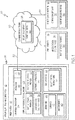
- FIG. 1 is schematic diagram illustrating an overarching AMQM supply chain or architecture 10, as illustrated in accordance with an exemplary embodiment of the present disclosure.
- AMQM architecture 10 is generically depicted as including a part supplier or vendor 12, which operates an AMQM system 18.
- AMQM system 18 may be utilized to carry-out certain embodiments of the methods described herein, as described more fully below. While only a single vendor 12 is shown in detail in the schematic of FIG. 1 , AMQM architecture 10 can contain (and embodiments of below-described AMQM method may be performed by) any practical number of vendors possessing suitably-equipped AMQM systems similar or identical to AMQM system 18. This is emphasized in FIG. 1 by symbol 26 ("x n ”) appearing adjacent the upper right corner of the box representing vendor 12.
- AMQM architecture 10 further contains a part designer 14 and a remote quality monitor 16.
- part designer 14 and remote quality monitor 16 may be the same entity in embodiments wherein part designer 14 performs the below-described quality control analysis processes.
- remote quality monitor 16 may be realized as a separate, third party entity, which has been authorized by designer 14 to conduct the below-described quality control analyses. This includes instances in which remote quality monitor 16 is implemented as a software application or algorithm, which executes as a cloud-based service 28 as further indicated in FIG. 1 and discussed more fully below.
- bidirectional communication between vendor 12, part designer 14, and quality monitor 16 occurs over a communications network 30.
- Communications network 30 can encompass any network or group of networks enabling data transmission between vendor 12, part designer 14, and quality monitor 16.
- communications network 30 can include one or more open CDNs, VPNs, the Internet, and various other communications networks implemented in accordance with TCP/IP protocol architectures or other conventional protocols.
- Network 30 may also encompass one or more wired or wireless LANs, WANs, a cellular network, and/or any other pubic or private networks.
- AM design data 34 can contain any suitable file type and will often contain or consist of one or more CAD files, which may be generated by part designer 14 utilizing various different commercially-available CAD program products.
- a non-exhaustive list of such commercially-available CAD program products includes TOPSOLID, CATIA, CREO, AUTODESK INVENTOR, SOLIDWORKS, and NX CAD software packages.
- the term "AM design data,” as appearing herein, thus broadly encompasses any computer-readable data or file types, which can be utilized by an AM machine to fabricate AM components in accordance with a predetermined design, regardless of the particular manner in which the data is stored or disseminated.
- At least one baseline sensor profile 36 is utilized to carry-out the quality comparison analysis.
- Part designer 14 may initially construct baseline sensor profile 36 by validating any desired number of AM proofing parts, which are produced by part designer 14 utilizing a non-illustrated AM machine, by vendor 12 utilizing AM machine 20, and/or by a different entity possessing a suitable-equipped AM machine.
- initial sensor profiles may be collected in the manner described below.
- Part designer 14, or another entity acting at the direction of designer 14 may then perform any number of tests on the AM proofing parts.
- the initially-gathered sensor profiles corresponding to those AM proofing parts, which pass testing or are otherwise validated, may then be utilized to construct baseline sensor profile 36.
- test or tests conducted will vary amongst embodiments in relation to design requirements and other factors.
- such tests may be designed to evaluate crack propagation and growth propensity, tensile strengths, high temperature creep propensity, life cycle fatigue properties, and similar characteristics within the high temperature GTE environment. It is not uncommon for the aggregate cost to perform such tests to approach or exceed several hundred thousand United Stated dollars. Such costs may be prohibitive to vendors, such as vendor 12 shown in FIG. 1 , and may thus impede usage of supply chains to obtained AM parts absent the AMQM system and methods described herein.
- baseline sensor profile 36 may be stored locally by AMQM system 18 in embodiments in which controller subsystem 24 conducts the below-described quality comparison analysis. In such implementations, local user access to and editing of baseline sensor profile 36 may be restricted or entirely prevented to ensure data integrity. Baseline sensor profile 36 may, however, be periodically updated by part designer 14 through secure cloud service 28. Finally, a further copy of baselines sensor profile 36 may be stored by remote quality monitor 16 in implementations wherein quality monitor 16 is utilized to perform offsite quality analysis in addition to or in lieu of onsite quality analysis. Again, although illustrated as external to secure cloud service 28 in FIG.
- remote quality monitor 16 can be implemented in software, firmware, or the like executed by one or more distributed servers in communication via network 30 (colloquially, the "cloud"), in which case baseline sensor profile 36 may be stored within cloud service 28.
- baseline sensor profile 36 may be stored within cloud service 28.
- mutual authentication and encryption techniques may be employed for data security purposes.
- Secure cloud service 28 may thus only avail AMQM system 18 of protected data (e.g., AM design data 34 ) and access to the below-described quality management services following proper authentication of vendor 12.
- secure cloud service 28 may maintain a database 38 of vendors approved by part designer 14. Vendor 12 may be required to unique, identifying information matching that stored in database 38 when establishing a data-sharing session with service 28 / quality monitor 16 over communications network 30.
- AMQM system 18 includes an AM apparatus or machine 20, a display device 22, and a controller subsystem 24, which is operatively coupled to AM machine 20 and display device 22.
- AM machine 20 can assume the form of any apparatus, system, or device suitable for fabricating AM components by successively building-up such parts, on a layer-by-layer basis, in accordance with CAD data files or other computer-readable AM design data.
- AM machine 20 can be a 3D printer capable of producing AM components utilizing an FFF AM processes.
- AM machine 20 may be an SLA or laser sintering (e.g., DMLS) apparatus.
- AM machine 20 may be capable of producing metallic AM components by, for example, heating a metallic source material (e.g., supplied as a filament (wire), powder bed, actively-flowed powder, or the like) utilizing a suitable heat input source (e.g., a laser or an electron beam), which creates weld pools to fuse together the source material in a targeted manner to gradually build-up or successively compile the desired component.
- the metallic source material may be a superalloy, such a nickel-based or cobalt-based superalloy, in implementations in which AMQM system 18 is utilized to produce GTE or aerospace parts.
- AM machine 20 may assume a different forms suitable for producing AM components or three dimensionally printed parts.
- the components fabricated utilizing AMQM system 18 are generically represented in FIG. 1 by box 40.
- AM machine 20 is equipped with one or more sensors 56.
- Sensors 56 can assume any form suitable for capturing measurements or readings pertaining to AM components 40, while such components are produced by AM machine 20.
- sensors 56 include at least one temperature sensor, such as a pyrometer, capable of measuring local fusion temperatures captured during layer-by-layer build-up of AM components 40.
- temperature measurements may be referred to as "fusion" or "weld pool” temperature measurements.
- fusion temperature measurements are captured over a time frame encompassing immediately prior to, during, and immediately after application of heat input fusing the source material.
- each AM component 40 This results in a fusion time-versus-temperature curve or characteristic, which can be gathered for each layer or for a subset of layers contained in each AM component 40.
- this data may yield a part-specific sensor profile 42, which can be compared against baseline sensor profile 36 during the quality analysis process, as discussed more fully below in conjunction with FIGs. 3-4 .
- Each part-specific sensor profile 42 can contain any number and type of data characteristics captured by sensors 56, with the discussion of time-phased temperature characteristics serving only as a useful and non-limiting example.
- sensors 56 may further include sensors capable of capturing various other parameters relating to AM components 40.
- sensors 56 may include one or more image sensors capable of capturing image data in the visible, infrared, and/or ultraviolet portions of the electromagnetic spectrums. Such image data may be utilized to calculate layer-by-layer dimensions of AM components, as captured during AM fabrication process and utilized to compile part-specific sensor profiles 42 and baseline sensor profile 36.
- sensors 56 may record or measure other parameters during the AM fabrication process, which do not directly pertain to AM components 40, but rather to the operating characteristics of AM machine 20, to the source material or materials from which AM components 40 are produced, to the internal environment within AM machine 20, and/or to the environment external to AM machine 20.
- sensors 56 includes measurements pertaining to: room temperature, pressure, and humidity levels; and temperature, pressure, humidity, and gas (e.g., O 2 ) levels within the process chamber or "print bed" of AM machine 20.
- sensors 56 may also measure parameters relating to the operation of AM machine 20, such as chiller state, collector position, filter pressure, recoater position and speed, and dispenser position.
- AMQM system 18 and, specifically, controller subsystem 24 compiles part-specific sensor profiles 42 for AM components 40 during fabrication of AM components 40.
- Controller subsystem 24 may perform quality analysis onsite by comparing and contrasting each part-specific sensor profile 42 with baseline sensor profile 36.
- controller subsystem 24 may transmit part-specific sensor profiles 42 over communications network 42 to remotely-located entity, such as remote quality monitor 16, which then conducts the quality analysis process utilizing the part-specific sensor profiles.
- both controller subsystem 24 and remote quality monitor 16 may perform independent analyses to each evaluate component quality based, at least in part, upon the degree to which sensor profiles 42 conform to baseline sensor profile 36.
- controller subsystem 24 further includes at least one processor 44, I/O features 46, and a computer-readable memory or storage medium 48.
- Processor 44 is operably coupled to I/O features 46 and to storage medium 48.
- I/O features 46 can include a network interface, an interface to storage medium 48, an interface to display device 22, and any user input interfaces enabling local users to interact with and control AMQM system 18.
- Storage medium 48 stores AM design data 34 and part-specific sensor profiles 36. Additionally, in embodiments wherein AMQM system 18 performs onsite quality analysis, storage medium 48 may further store baseline sensor profile 36 and specialized software application 50. Comparison software application 50 may contain computer-executable code that, when executed by processor 44, causes AMQM system 18 to perform the below-described AMQM process. Similarly, when utilized to perform offsite or independent quality analysis, remote quality monitor 16 may likewise contain suitable computer-executable comparison software 52.
- controller subsystem 24 can each be implemented utilizing any suitable number and combination of known devices including microprocessors, memories, power supplies, storage devices, interface cards, and other standard components. Such components may include or cooperate with any number of software programs or instructions (e.g.., software application 50 ) designed to carry-out the various methods, process tasks, encoding and decoding algorithms, and relevant display functions.
- processor 44 selectively executes computer-readable code or instructions (herein, "software application 50 "), which directs the various hardware features of AMQM system 18 to perform the functions described herein.
- Software application 50 interfaces with processor 44, storage medium 48, and I/O features 46 via any suitable operating system to provide these functionalities.
- Software application 50 can be provided to AMQM system 18 in any manner, including by download through communications network 30 from part designer 14 or secure cloud service 28.
- control logic contained in software application 50 may control sensors 56, AM machine 20, and/or display device 22. Additionally, when executed, software application 50 may selectively generate quality control notifications 54 on a display screen of display device 22.
- Quality control notifications 54 may indicate which, if any of AM components 40 are desirably subject to remedial action. Additionally, in certain instances, quality control notifications 54 may be expressed as textual annunciations or readouts, which contain additional actions to be performed for those AM components 40 subject to remedial action.
- Software application 50 may further selectively establish connections through communications network with appropriate remote entities (e.g., secure cloud service 28, part designer 14, and/or remote quality monitor 16 ), as appropriate for a given implementation of the AMQM process. Additional description of exemplary AMQM processes will now be set-forth in conjunction with FIG. 2 .
- FIG. 2 is a message timing diagram of an exemplary AMQM process 60, which may be carried-out between vendor 12, part designer 14, and remote quality monitor 16 in an exemplary embodiment of the present disclosure.
- quality control comparison are performed offsite by remote quality monitor 16.
- quality control comparison can also be performed onsite by AMQM system 18 in addition to or in lieu of offsite quality control analysis further embodiments of process 60.
- AM design data e.g., AM design data 34, FIG. 1
- a baseline sensor profile e.g., baseline sensor profile 36, FIG. 1
- AM design data can be one or more CAD files or similar computer-readable object data defining the 3D design of the components to be produced by vendor-operated AMQM system 18 ( FIG. 1 ).
- the baseline sensor profile can be generated directly by part designer 14 or by a third party at the request of designer 14.
- proofing parts may be initially produced utilizing a suitably-equipped AM machine, the proofing parts may be tested, and sensor readings captured during production of those proofing parts validated through testing may then be utilized to generate the baseline sensor profile.
- one or more of the AM proofing parts may be fabricated by vendor 12 utilizing the same AMQM system subsequently used to fabricate the production-run AM components. The AM proofing parts may then be shipped or otherwise provided to part designer 14, or another entity associated with the part designer, for validation testing.
- part designer 14 may provide the baseline sensor profile to remote quality monitor 16 (FUNCTION 64, FIG. 2 ).
- part designer 14 may place a purchase order with vendor 12 and provides the corresponding AM design data to vendor 12 (FUNCTIONS 66, 68, FIG. 2 ). Afterwards or concurrently, part designer 14 may also provide information to remote quality monitor 16 for usage in subsequently authorizing vendor 12 as a trusted entity (FUNCTIONS 70, 72, FIG. 2 ). Data utilized in public-key encryption or private-key encryption techniques (e.g., as employed utilizing Advanced Encryption Standard (AES) standards) may be provided, with the appropriate key or keys provided to both vendor 12 and remote quality monitor 16. If vendor 12 is not currently listed within database 38, part designer 14 may instruct remote quality monitor 16 to add vendor 12 to vendor database 38 stored by secure cloud service 28 ( FIG. 1 ).
- AES Advanced Encryption Standard
- Vendor 12 next utilizes AMQM system 18 ( FIG. 1 ) to fabricate AM components in accordance with the AM design data previously forwarded by part designer 14 (FUNCTION 74, FIG. 2 ).
- vendor 12 / AMQM system 18 utilizes sensors 56 to capture sensor readings and compile part-specific sensor profiles.
- AMQM system 18 may capture such sensor readings automatically or in automated manner (that is, without requiring additional manual input by vendor 12 ) by execution of software application 50 ( FIG. 1 ) by controller subsystem 24 / processor 44.
- AMQM system 18 will typically compile the part-specific senor profiles for all AM components produced by AM machine 20; however, this not necessary in all implementations. As discussed more fully below in conjunction with FIGs.
- the parameters gathered to compile each part-specific sensor profile may include sensor measurements for every additively-built layer contained within a given AM component or, perhaps, for only a subset of layers.
- vendor 12 / AMQM system 18 then forwards the part-specific senor profiles to remote quality monitor 16 (FUNCTION 80, FIG. 2 ). Again, this may occur as an encrypted transmission occurring over communications network 30 ( FIG. 1 ). Vendor 12 / AMQM system 18 may also append any such transmission to include unique information confirming the identity of vendor 12 for authentication purposes.
- One or more the part-specific senor profiles may be transmitted to remote quality monitor 16 after the production of each AM component, after a predetermined number of AM components has been produced, or after the entire production run of the AM components has been fabricated.
- remote quality monitor 16 After receiving sensor profiles 42 from vendor 12 / AMQM system 18, remote quality monitor 16 utilizes the part-specific senor profiles to evaluate the quality of the corresponding the AM components (FUNCTION 78, FIG. 2 ).
- the algorithm or algorithms utilized for this purpose, as contained in comparison software 52 ( FIG. 1 ), will vary amongst embodiments, as will the degree to which the part-specific senor profiles are permitted to deviate from the baseline sensor profile before the corresponding the AM components are deemed non-compliant and, thus, desirably subject to remedial action or corrective measures.
- Various aspects of the data sets may be compared and contrasted during the analysis process, with an example provided below in conjunction with FIGs. 3 and 4 .
- the results of the quality control analysis are then returned to vendor 12 / AMQM system 18 (FUNCTION 80, FIG. 2 ).
- the quality control results are then presented at AMQM system 18 as, for example, visual quality control notifications presented on display device 22 ( FIG. 1 ). Audible alerts or advisory messages may also be provided, if desired.
- the quality control notifications generated at FUNCTION 82 usefully indicate whether any of the AM components produced by AM machine 20 are desirably subject to remedial action.
- remedial action can include rejection or further testing of any non-conforming AM components.
- part serial numbers or other such identifying information
- Recommended or required remedial actions might also be provided as part of the quality control notifications presented on the screen of display device 22 or otherwise generated at AMQM system 18. For example, in the case of an AM component for which the corresponding sensor profile is only moderately non-conformal with the baselines senor profile, the recommended or required remedial action might be further testing or simple visual inspection of the corresponding AM component.
- AMQM system 18 may temporarily halt fabrication of the AM components when determining that a currently-printed AM component is desirably subject to remedial action or when the part-specific senor profile gathered for the AM component is severely non-conformal with the baseline sensor profile. In this manner, vendor 12 may be provided with a noticeable cue to ensure that AMQM system 18 is in proper working order before further printing of the AM components continues.
- the above-process steps may be repeated until such time as vendor 12 / AMQM system 18 fabricates an adequate number of AM components having conforming sensor profiles.
- AMQM system 18 may repeat these process steps until enough AM components having conforming sensor profiles are produced to satisfy the previously-placed purchase order.
- the AMQM method carried-out by AMQM system 18 concludes (FUNCTION 88, FIG. 2 ).
- Vendor 12 may then ship the AM components to the desired destination or destinations; e.g., the newly-fabricated AM component lot may be shipped to part designer 14 and/or another entity for further assembly and processing.
- remote quality monitor 16 may then generate an independent quality report, which is forwarded directly to part designer 14 (FUNCTION 92, FIG. 2 ).
- the independent quality report may indicate that vendor 12 / AMQM system 18 has successfully produced an adequate number of AM components having conforming part-specific sensor profiles. This provides an independent check or quality assuredness measure in the AM supply chain.
- FIG. 3 is a top-down view of a metallic powder bed 102 included in an exemplary DMLS machine 100, as illustrated during production of a generic AM component 40 for which a part-specific sensor profile may be gathered.
- DMLS machine 100 may correspond to AM machine 20 shown in FIG. 1 in an exemplary and non-limiting embodiment.
- DMLS machine 100 includes various other components, which are well-known in the relevant field and not shown in FIG. 3 to avoid obscuring the drawing.
- a directed heat beam (laser or electron beam) is scanned over selected regions of metallic powder bed 102 to fuse layers of metal powder and gradually build-up or successively compile component 40 on a layer-by-layer basis.
- FIG. 3 One such fused metal layer 104 included in component 40 (shown in a partially-completed state) is depicted in FIG. 3 .
- a dummy structure e.g., a column-like coupon 106
- Coupon 106 thus represents a structure, which is printed concurrently with component 40, but which is physically separate or independent therefrom.
- AM component 40 After selected regions of a given metallic layer included within AM component 40 are fused by controlled heat input, additional powder layers may then be applied over the recently-fused layer utilizing a non-illustrated powder delivery system (e.g., a roller-based recoater system).
- a non-illustrated powder delivery system e.g., a roller-based recoater system.
- This process of dispensing a metallic powder layer, fusing selected regions of the metallic powder layer, and then apply a fresh metallic powder layer are repeated on an iterative basis. In this manner, numerous layers of fused metal are built-up or compiled in the Z-direction identified by coordinate legend 108 in FIG. 3 and complete AM component 40.
- multiple AM components may be fabricated in parallel within metallic powder bed 102.
- other types of metal AM processes can be employed to produce component 40 including DED metal AM processes in which a source metal is continually supplied to a fusion site as, for example, a flowing powder or actively-fed wire.
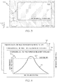
- part-specific sensor profile 110, 112, 114 contains sensor readings for all layers contained within AM component 40. This is indicated in FIG. 4 by the labeled entitled "layer 1,” layer 2," and a final “layer n ,” with the sensor readings for the intermediate layers between "layer 2" and “layer n " not shown for clarity. In further embodiments, such sensor readings may be gathered for only a subset of layers contained within AM component 40.
- sensor readings may only be gathered for every other layer, for every third layer, or for some other predetermined subset of the printed layers.
- the sensor readings are gathered as time-phased temperature measurements.
- One such time-phased temperature measurement is shown in FIG. 4 for layer n and identified by reference numeral "116."
- the time-phased temperature measurement 116 include a trace, curve, or characteristic plotting local temperature-versus-time over a timeframe encompassing a fusion event. This data is referred to below as Fusion Temperature-versus-Time (FTT) characteristic.
- FTT Fusion Temperature-versus-Time
- a FTT characteristic may be recorded for a given X-, Y-coordinate location (corresponding to coordinate legend 108, FIG. 3 ).
- the X-, Y-coordinate location may be coincident within an selected region of AM component 40 ( FIG. 3 ) or, instead, may be coincident with another site of fusion remotely located from component 40.
- the layer-specific FTT characteristics contained in part-specific senor profile 110, 112, 114 can be recorded at a fixed X-, Y-coordinate location corresponding to coupon 106 in FIG.
- AM component 40 may be flagged for remedial action during AMQM processes described above in conjunction with FIGs. 1 and 2 .
- remedial action may entail testing, which, in this case, may involve additional inspection of AM component 40 part itself, testing of coupon 106 concurrently printed with AM component 40, or a combination thereof.
- a comparative analysis is carried-out to determine whether a meaningful discrepancy exists between the baseline sensor profile (itself containing one or more FTT baseline characteristics) and the newly-collected FTT characteristics contained in part-specific senor profile 110, 112, 114.
- each FTT characteristic may be compared to the FTT baseline sensor profile. If the FTT baseline sensor profile contains only a single FTT model characteristic, each layer-specific FTT characteristic contained in part-specific senor profile 110, 112, 114 may be compared to the FTT model characteristic on an individual basis.
- the layer-specific FTT characteristics contained in part-specific senor profile 110, 112, 114 may each be compared to the corresponding FTT model characteristics; e.g., FTT model characteristic 110 gathered for layer 1 may be compared with a corresponding FTT model characteristic for layer 1 contained in the baseline sensor profile, FTT model characteristic 112 gathered during fusion of layer 2 may be compared with a corresponding FTT model characteristic for layer 2 contained in the baseline sensor profile, and so on.
- Conformance with the baseline sensor profile may be determined utilizing an algorithm (e.g., as contained in software application 50, 52 in FIG. 1 ) adapted to analytically compare one or more parameters of layer-specific FTT characteristics contained in part-specific senor profile 110, 112, 114 to the corresponding FTT characteristics in the baselines sensor profile.
- Such parameters can consider various deviations between different factors of the data sets including, for example, average slopes, bilateral symmetry (as divided at the peak recorded temperature), the magnitude of the maximum recorded temperature, and the like.
- the duration of time at which the fusion or weld pool remains above a predetermined temperature e.g., a minimum temperature or liquidation temperature at which fusion will occur, as indicated in FIG.
- processor 44 executing software 50 may compare the time period over which the recorded fusion temperatures remain above a minimum fusion temperature (horizontal line 120, FIG. 4 ) in determining whether the part-specific sensor profiles adequately conform with the baseline sensor profile.
- a minimum fusion temperature horizontal line 120, FIG. 4
- AMQM systems and methods enabling improved quality management of AM components sourced through supply chains.
- the above-described AMQM processes provides versatile and powerful quality checks in the context of AM supply chains. This quality check can be performed on AM components produced a wide range of vendors, regardless of location and whether a particular vendor lacks the financial resources and/or expertise to independently evaluate such parts.
- Embodiments of the above-described systems and methods can be implemented in a relatively seamless, cost-effective manner through the installation of software applications or program products operating on preexisting systems.
- high integrity, tamper-resistant quality control measures governing the production and distribution of AM components are provided, at least in part, through the generation of quality control reports, which are transmitted to the part designer in an automated fashion by the AMQM system and/or by a remote quality monitor in communication with the AMQM system.
- Embodiments of the above-described AMQM systems and methods may be beneficially applied to the fabrication of AM aerospace and turbomachinery component including ECS, ATS, and GTE components. More generally, embodiments of the present disclosure can be utilized in conjunction with the fabrication of any type of AM component, without limitation, obtained through a supply chain and desirably subject to enhanced quality control measures.
Landscapes
- Engineering & Computer Science (AREA)
- Manufacturing & Machinery (AREA)
- Chemical & Material Sciences (AREA)
- Materials Engineering (AREA)
- Physics & Mathematics (AREA)
- Human Computer Interaction (AREA)
- General Physics & Mathematics (AREA)
- Automation & Control Theory (AREA)
- Mechanical Engineering (AREA)
- Optics & Photonics (AREA)
Applications Claiming Priority (1)
| Application Number | Priority Date | Filing Date | Title |
|---|---|---|---|
| US15/619,172 US10386818B2 (en) | 2017-06-09 | 2017-06-09 | Quality management systems, methods, and program products for additive manufacturing supply chains |
Publications (1)
| Publication Number | Publication Date |
|---|---|
| EP3413151A1 true EP3413151A1 (fr) | 2018-12-12 |
Family
ID=62683088
Family Applications (1)
| Application Number | Title | Priority Date | Filing Date |
|---|---|---|---|
| EP18175276.7A Pending EP3413151A1 (fr) | 2017-06-09 | 2018-05-30 | Systèmes de gestion de qualité, procédés et produits-programmes de chaînes d'approvisionnement de fabrication additive |
Country Status (2)
| Country | Link |
|---|---|
| US (1) | US10386818B2 (fr) |
| EP (1) | EP3413151A1 (fr) |
Families Citing this family (4)
| Publication number | Priority date | Publication date | Assignee | Title |
|---|---|---|---|---|
| JP6351880B2 (ja) * | 2016-01-15 | 2018-07-04 | 三菱電機株式会社 | 計画生成装置、計画生成方法及び計画生成プログラム |
| US11127204B2 (en) * | 2017-08-15 | 2021-09-21 | Siemens Industry Software Inc. | Boundary characteristic-based part processing in support of additive manufacturing |
| EP3502806A1 (fr) * | 2017-12-22 | 2019-06-26 | Siemens Aktiengesellschaft | Procédé de protection des données de production pour la fabrication d'un produit |
| EP3989140A1 (fr) * | 2020-10-21 | 2022-04-27 | Honeywell International Inc. | Systèmes et procédés de gestion et de contrôle de la qualité distribués pour la fabrication décentralisée au moyen de dispositifs de capteurs connectés |
Citations (4)
| Publication number | Priority date | Publication date | Assignee | Title |
|---|---|---|---|---|
| US20160098825A1 (en) * | 2014-10-05 | 2016-04-07 | Sigma Labs, Inc. | Feature extraction method and system for additive manufacturing |
| US20160217518A1 (en) * | 2015-01-27 | 2016-07-28 | Joseph M. Shapiro | Custom Sexual Stimulation Device Production System And Method |
| US20160283833A1 (en) * | 2015-03-23 | 2016-09-29 | Intel Corporation | Printer monitoring |
| WO2017035004A1 (fr) * | 2015-08-21 | 2017-03-02 | Voxel8, Inc. | Impression 3d en boucle fermée comprenant une rétroaction de capteur |
Family Cites Families (13)
| Publication number | Priority date | Publication date | Assignee | Title |
|---|---|---|---|---|
| US8044880B2 (en) * | 2005-04-28 | 2011-10-25 | Hitachi, Ltd. | Projection type image display device |
| US9471891B2 (en) * | 2010-09-24 | 2016-10-18 | Nulogy Corporation | Method, system and apparatus for automatic quality control using a plurality of computers |
| US9604406B2 (en) * | 2011-04-27 | 2017-03-28 | Grow Software Limited | Three-dimensional design and manufacturing systems |
| PL2543277T3 (pl) * | 2011-07-06 | 2016-12-30 | Sekcja czyszcząca elektrycznego urządzenia do higieny jamy ustnej | |
| US9228859B2 (en) * | 2011-09-26 | 2016-01-05 | Northeastern University | Customizable embedded sensors |
| KR101482707B1 (ko) * | 2013-02-27 | 2015-01-14 | 한국과학기술원 | 디스플레이 기판 및 커버 윈도우용 유리섬유직물이 함침된 무색투명 폴리이미드 필름의 표면 평탄화 방법 |
| IL227598B (en) * | 2013-07-22 | 2018-05-31 | Verint Systems Ltd | Systems and methods for identifying malicious hosts |
| US10207363B2 (en) * | 2014-03-24 | 2019-02-19 | James Eldon Craig | Additive manufacturing temperature controller/sensor apparatus and method of use thereof |
| DE102014208768B4 (de) | 2014-05-09 | 2019-07-11 | MTU Aero Engines AG | Verfahren und Vorrichtung zur Qualitätssicherung |
| DE102015011013B4 (de) | 2014-08-22 | 2023-05-04 | Sigma Additive Solutions, Inc. | Verfahren zur Überwachung von generativen Fertigungsprozessen |
| WO2016115284A1 (fr) | 2015-01-13 | 2016-07-21 | Sigma Labs, Inc. | Système et méthodologie de qualification de matière |
| KR102385375B1 (ko) * | 2015-07-13 | 2022-04-11 | 에스케이이노베이션 주식회사 | 신규한 레지스트 하층막 형성용 중합체, 이를 포함하는 레지스트 하층막 형성용 조성물 및 이를 이용한 레지스트 패턴의 형성 방법 |
| US10735131B2 (en) * | 2016-08-24 | 2020-08-04 | Global Tel*Link Corporation | System and method for detecting and controlling contraband devices in a correctional facility utilizing portable electronic devices |
-
2017
- 2017-06-09 US US15/619,172 patent/US10386818B2/en active Active
-
2018
- 2018-05-30 EP EP18175276.7A patent/EP3413151A1/fr active Pending
Patent Citations (4)
| Publication number | Priority date | Publication date | Assignee | Title |
|---|---|---|---|---|
| US20160098825A1 (en) * | 2014-10-05 | 2016-04-07 | Sigma Labs, Inc. | Feature extraction method and system for additive manufacturing |
| US20160217518A1 (en) * | 2015-01-27 | 2016-07-28 | Joseph M. Shapiro | Custom Sexual Stimulation Device Production System And Method |
| US20160283833A1 (en) * | 2015-03-23 | 2016-09-29 | Intel Corporation | Printer monitoring |
| WO2017035004A1 (fr) * | 2015-08-21 | 2017-03-02 | Voxel8, Inc. | Impression 3d en boucle fermée comprenant une rétroaction de capteur |
Also Published As
| Publication number | Publication date |
|---|---|
| US10386818B2 (en) | 2019-08-20 |
| US20180356796A1 (en) | 2018-12-13 |
Similar Documents
| Publication | Publication Date | Title |
|---|---|---|
| US11809159B2 (en) | Managing blockchains in an industrial facility based on firmware change | |
| EP3413151A1 (fr) | Systèmes de gestion de qualité, procédés et produits-programmes de chaînes d'approvisionnement de fabrication additive | |
| CN110554047B (zh) | 产品缺陷检测数据处理方法、装置、系统和设备 | |
| EP3564881A1 (fr) | Dispositifs industriels activés par blockchain | |
| Chen et al. | A review on qualification and certification for metal additive manufacturing | |
| US20210382667A1 (en) | System, Method, and Program Product for Digital Production Management | |
| US10725459B2 (en) | Identifying and distributing optimal machine parameters within a fleet of additive manufacturing machines | |
| US10268182B2 (en) | Detection of the integrity of additively manufactured parts | |
| EP3766205B1 (fr) | Système et procédé de protection d'éléments associés à une fabrication additive | |
| JP2016094185A (ja) | ソフトウェア航空機部品の実装システム | |
| CN114253941A (zh) | 使用工业信息中心的数据建模和资产管理 | |
| CN114257609B (zh) | 用于提供工业信息服务的系统、方法和计算机可读介质 | |
| US20180293591A1 (en) | System and Method for Authenticating Components Using Dual Key Authentication | |
| WO2019067471A2 (fr) | Systèmes et procédés de réalisation d'une surveillance in situ en fabrication additive | |
| KR102133901B1 (ko) | 스마트팩토리의 모니터링과 관리시스템을 위한 보안 시스템 | |
| EP3934200A1 (fr) | Systèmes et procédés de gestion et de contrôle de la qualité distribués pour la fabrication décentralisée au moyen d'une chaîne de blocs | |
| KR102324747B1 (ko) | 네트워크 기반 3d 프린팅 통합시스템 | |
| US20220004164A1 (en) | Distributed quality management and control systems and methods for decentralized manufacturing using blockchain | |
| EP3989140A1 (fr) | Systèmes et procédés de gestion et de contrôle de la qualité distribués pour la fabrication décentralisée au moyen de dispositifs de capteurs connectés | |
| US20220121172A1 (en) | Distributed quality management and control systems and methods for decentralized manufacturing using connected sensor devices | |
| CN112703456A (zh) | 数据结构产品和产品套件 | |
| EP4345719A1 (fr) | Gestion de données de chaîne de blocs d'automatisation industrielle | |
| EP4345713A1 (fr) | Contrats intelligents basés sur les performances dans l'automatisation industrielle | |
| US20240106666A1 (en) | INDUSTRIAL AUTOMATION MANUFACTURING WITH NFTs AND SMART CONTRACTS | |
| US20240106667A1 (en) | Tokenized industrial automation software |
Legal Events
| Date | Code | Title | Description |
|---|---|---|---|
| PUAI | Public reference made under article 153(3) epc to a published international application that has entered the european phase |
Free format text: ORIGINAL CODE: 0009012 |
|
| STAA | Information on the status of an ep patent application or granted ep patent |
Free format text: STATUS: REQUEST FOR EXAMINATION WAS MADE |
|
| 17P | Request for examination filed |
Effective date: 20180530 |
|
| AK | Designated contracting states |
Kind code of ref document: A1 Designated state(s): AL AT BE BG CH CY CZ DE DK EE ES FI FR GB GR HR HU IE IS IT LI LT LU LV MC MK MT NL NO PL PT RO RS SE SI SK SM TR |
|
| AX | Request for extension of the european patent |
Extension state: BA ME |
|
| STAA | Information on the status of an ep patent application or granted ep patent |
Free format text: STATUS: REQUEST FOR EXAMINATION WAS MADE |
|
| STAA | Information on the status of an ep patent application or granted ep patent |
Free format text: STATUS: EXAMINATION IS IN PROGRESS |
|
| 17Q | First examination report despatched |
Effective date: 20210315 |
|
| STAA | Information on the status of an ep patent application or granted ep patent |
Free format text: STATUS: EXAMINATION IS IN PROGRESS |
|
| RAP3 | Party data changed (applicant data changed or rights of an application transferred) |
Owner name: HONEYWELL INTERNATIONAL INC. |
|
| P01 | Opt-out of the competence of the unified patent court (upc) registered |
Effective date: 20230421 |
|
| GRAP | Despatch of communication of intention to grant a patent |
Free format text: ORIGINAL CODE: EPIDOSNIGR1 |
|
| STAA | Information on the status of an ep patent application or granted ep patent |
Free format text: STATUS: GRANT OF PATENT IS INTENDED |
|
| INTG | Intention to grant announced |
Effective date: 20240322 |