EP3413147B1 - Method for controlling a plc using a pc program - Google Patents
Method for controlling a plc using a pc program Download PDFInfo
- Publication number
- EP3413147B1 EP3413147B1 EP17174804.9A EP17174804A EP3413147B1 EP 3413147 B1 EP3413147 B1 EP 3413147B1 EP 17174804 A EP17174804 A EP 17174804A EP 3413147 B1 EP3413147 B1 EP 3413147B1
- Authority
- EP
- European Patent Office
- Prior art keywords
- plc
- program
- source code
- data
- controlling
- Prior art date
- Legal status (The legal status is an assumption and is not a legal conclusion. Google has not performed a legal analysis and makes no representation as to the accuracy of the status listed.)
- Active
Links
- 238000000034 method Methods 0.000 title claims description 61
- 238000004590 computer program Methods 0.000 claims description 7
- 230000001419 dependent effect Effects 0.000 claims description 5
- 230000008569 process Effects 0.000 description 36
- 239000000969 carrier Substances 0.000 description 5
- 238000004519 manufacturing process Methods 0.000 description 5
- 238000011161 development Methods 0.000 description 4
- 230000018109 developmental process Effects 0.000 description 4
- 230000004048 modification Effects 0.000 description 3
- 238000012986 modification Methods 0.000 description 3
- 239000004065 semiconductor Substances 0.000 description 3
- 230000000007 visual effect Effects 0.000 description 3
- 239000011800 void material Substances 0.000 description 3
- 230000009471 action Effects 0.000 description 2
- 230000008901 benefit Effects 0.000 description 2
- 238000004891 communication Methods 0.000 description 2
- 238000010586 diagram Methods 0.000 description 2
- 230000006870 function Effects 0.000 description 2
- 238000009877 rendering Methods 0.000 description 2
- 101000857680 Xenopus laevis Runt-related transcription factor 1 Proteins 0.000 description 1
- 230000004888 barrier function Effects 0.000 description 1
- 238000004364 calculation method Methods 0.000 description 1
- 230000008859 change Effects 0.000 description 1
- 238000004140 cleaning Methods 0.000 description 1
- 238000011156 evaluation Methods 0.000 description 1
- 238000007689 inspection Methods 0.000 description 1
- 238000012544 monitoring process Methods 0.000 description 1
- 230000002093 peripheral effect Effects 0.000 description 1
- 239000000758 substrate Substances 0.000 description 1
- 230000009466 transformation Effects 0.000 description 1
- 238000012800 visualization Methods 0.000 description 1
Images
Classifications
-
- G—PHYSICS
- G05—CONTROLLING; REGULATING
- G05B—CONTROL OR REGULATING SYSTEMS IN GENERAL; FUNCTIONAL ELEMENTS OF SUCH SYSTEMS; MONITORING OR TESTING ARRANGEMENTS FOR SUCH SYSTEMS OR ELEMENTS
- G05B19/00—Programme-control systems
- G05B19/02—Programme-control systems electric
- G05B19/04—Programme control other than numerical control, i.e. in sequence controllers or logic controllers
- G05B19/05—Programmable logic controllers, e.g. simulating logic interconnections of signals according to ladder diagrams or function charts
- G05B19/056—Programming the PLC
-
- G—PHYSICS
- G05—CONTROLLING; REGULATING
- G05B—CONTROL OR REGULATING SYSTEMS IN GENERAL; FUNCTIONAL ELEMENTS OF SUCH SYSTEMS; MONITORING OR TESTING ARRANGEMENTS FOR SUCH SYSTEMS OR ELEMENTS
- G05B19/00—Programme-control systems
- G05B19/02—Programme-control systems electric
- G05B19/04—Programme control other than numerical control, i.e. in sequence controllers or logic controllers
- G05B19/042—Programme control other than numerical control, i.e. in sequence controllers or logic controllers using digital processors
- G05B19/0426—Programming the control sequence
-
- G—PHYSICS
- G05—CONTROLLING; REGULATING
- G05B—CONTROL OR REGULATING SYSTEMS IN GENERAL; FUNCTIONAL ELEMENTS OF SUCH SYSTEMS; MONITORING OR TESTING ARRANGEMENTS FOR SUCH SYSTEMS OR ELEMENTS
- G05B19/00—Programme-control systems
- G05B19/02—Programme-control systems electric
- G05B19/04—Programme control other than numerical control, i.e. in sequence controllers or logic controllers
- G05B19/05—Programmable logic controllers, e.g. simulating logic interconnections of signals according to ladder diagrams or function charts
- G05B19/054—Input/output
-
- G—PHYSICS
- G05—CONTROLLING; REGULATING
- G05B—CONTROL OR REGULATING SYSTEMS IN GENERAL; FUNCTIONAL ELEMENTS OF SUCH SYSTEMS; MONITORING OR TESTING ARRANGEMENTS FOR SUCH SYSTEMS OR ELEMENTS
- G05B19/00—Programme-control systems
- G05B19/02—Programme-control systems electric
- G05B19/04—Programme control other than numerical control, i.e. in sequence controllers or logic controllers
- G05B19/05—Programmable logic controllers, e.g. simulating logic interconnections of signals according to ladder diagrams or function charts
- G05B19/058—Safety, monitoring
-
- G—PHYSICS
- G06—COMPUTING; CALCULATING OR COUNTING
- G06F—ELECTRIC DIGITAL DATA PROCESSING
- G06F8/00—Arrangements for software engineering
- G06F8/30—Creation or generation of source code
- G06F8/33—Intelligent editors
-
- G—PHYSICS
- G06—COMPUTING; CALCULATING OR COUNTING
- G06F—ELECTRIC DIGITAL DATA PROCESSING
- G06F8/00—Arrangements for software engineering
- G06F8/30—Creation or generation of source code
- G06F8/34—Graphical or visual programming
-
- G—PHYSICS
- G06—COMPUTING; CALCULATING OR COUNTING
- G06F—ELECTRIC DIGITAL DATA PROCESSING
- G06F8/00—Arrangements for software engineering
- G06F8/40—Transformation of program code
- G06F8/51—Source to source
-
- G—PHYSICS
- G06—COMPUTING; CALCULATING OR COUNTING
- G06F—ELECTRIC DIGITAL DATA PROCESSING
- G06F8/00—Arrangements for software engineering
- G06F8/30—Creation or generation of source code
- G06F8/38—Creation or generation of source code for implementing user interfaces
Definitions
- US 2014/0123104 A1 discloses a method for the programming and configuration of a programmable logic controller, comprising: locating a configuration tool in a programming tool, wherein the configuration tool includes a module in an IEC61131 language; integrating at least one further module into the configuration tool; and executing the programming and configuration of the programmable logic controller in a high-level language using a C-Code editor, and wherein the at least one further module is configured to provide a definition of interfaces between an IEC61131 code and a high-level language code and a configuration of the high-level language code.
- SCADA frame of'supervisory control and data acquisition'
- SCADA is a control system architecture that uses PCs, networked data communications and graphical user interfaces for high-level process supervisory management, but uses other peripheral devices such as PLCs and discrete PID controllers to interface to the process plant or machinery.
- PLCs peripheral devices
- PID controllers discrete PID controllers
- the operator interfaces which enable monitoring and the issuing of process commands, such as controller set point changes, are handled through the SCADA supervisory computer system.
- the real-time control logic or controller calculations are performed by networked modules which connect to the field sensors and actuators.
- a computer program according to the invention comprising a program code causes a computer to perform all steps of one of the methods according to the invention, when the computer program is run on the computer.
- Suitable non-transitory machine readable media for providing the computer program are particularly floppy disks, hard disks, flash memory, EEPROMs, CD-ROMs, and DVDs etc.
- a download of a program on computer networks is advantageous.
- a heater 15 to heat the chamber up to a desired temperature and a rotatable plate being rotated by an electromotor 17 with a desired speed.
Description
- The present invention relates to a method for automatically creating a PC program for controlling a PLC according to claim 1, and a computer program for performing this method according to
claim 12. preferred embodiments of the invention are defined by the dependent claims. - A PLC (Programmable Logic Controller) is a device for controlling process plants or machineries and is digitally programmed. A PLC usually has inputs, outputs, a firmware (operating system) and an interface for downloading the application program. The application program defines how the outputs are set depending on the inputs. The firmware makes available the inputs and outputs for the application program.
- The PLC as a real time system connects with digital or analog sensors, and controls the actuators such as pneumatic or hydraulic cylinders or electrical motors of the process plant or machinery. For many machine control applications, especially semiconductor manufacturing machine applications, there is typically a personal computer (PC) application connected to the PLC and also the factory network (e.g. host system in a semiconductor fabrication plant, also known as a fab or foundry): it reads these sensor values from PLC, performs high level management on these acquired real time data (e.g. sends these data to the fab host as status variables), and sends commands to the PLC to perform respective actions.
-
US 2014/343696 A1 discloses a control environment, which can be embodied as a PLC and which controls operation of equipment like a production process. A rendering environment is provided for displaying industrial automation data. The control environment can comprise machine-executable control code that controls the operation of equipment. A terminal of the rendering environment includes processor(s) to execute computer-executable code instructions. -
US 2014/0123104 A1 discloses a method for the programming and configuration of a programmable logic controller, comprising: locating a configuration tool in a programming tool, wherein the configuration tool includes a module in an IEC61131 language; integrating at least one further module into the configuration tool; and executing the programming and configuration of the programmable logic controller in a high-level language using a C-Code editor, and wherein the at least one further module is configured to provide a definition of interfaces between an IEC61131 code and a high-level language code and a configuration of the high-level language code. - In a classical PC application, the problem is that whenever there is an evolution on the PLC application side, e.g. adding a new sensor or adding a new actuator, there is also a considerable amount of modification work on the PC application side to implement the basic functions to access these newly added elements, for example:
- Create/modify documentation of the PLC interface regarding the newly added sensors/actuators that PC can access
- Add additional communication links between the PLC and PC application for the newly added elements
- Create internal variables/procedures in the PC program which represents the newly added elements
- Create/modify graphic user interface of the PC program to display the newly added sensors, and to provide the possibility to send command to the PLC to control the newly added actuators
- One can expose internal variables of the PLC to the PC for reading and/or writing, using e.g. an OPC server. However, even then the PC program has to be adapted manually to use newly provided variables.
- It is thus desirable to reduce the necessary work involved in adapting the PC program to evolutions on the PLC application side.
- According to the invention, a method, a computer program and a computer for controlling a PLC using a PC program with the features of the independent claims are proposed. Advantageous further developments form the subject matter of the dependent claims and of the subsequent description.
- This invention introduces a method and its implementation to automatically generate a PC program, preferably having a graphical user interface (GUI), for communicating with and/or controlling the PLC based on data read out from a data section of the source code of the PLC program and a PC program template. In other words, the data section serves as a common source code portion for both the PC program and the PLC program. Thus, errors introduced by manually adapting the PC program to evolutions on the PLC application side can be prevented. Within the PLC program, the data section includes data indicating or declaring, respectively, services to be exposed by the PLC when running the PLC program, and can be used by a corresponding service exposing procedure; within the PC program, these data can be used to know which services are actually exposed and can be used by a corresponding service connecting procedure, and preferably can be used by a GUI creating procedure in order to create visual elements (input or output) for every exposed service.
- The invention intends to save development time on the PC program side when there is an evolution or change on the PLC program side that requires the PC to implement these changes too. The PLC program side, i.e. the source code of the PLC program, still has to be adapted; however, the PC program does not require any further development. If the PLC program source code is defined or changed, only the changed data section has to be combined with the PC program template to create a new PC program source code. This saves significant development time on the PC side, avoids human errors and performs automatic functionality coherence check.
- The invention can be used advantageously in the frame of'supervisory control and data acquisition' (SCADA). SCADA is a control system architecture that uses PCs, networked data communications and graphical user interfaces for high-level process supervisory management, but uses other peripheral devices such as PLCs and discrete PID controllers to interface to the process plant or machinery. The operator interfaces which enable monitoring and the issuing of process commands, such as controller set point changes, are handled through the SCADA supervisory computer system. However, the real-time control logic or controller calculations are performed by networked modules which connect to the field sensors and actuators.
- According to a preferred embodiment, the source code of the PLC program is a high-level programming language, especially C-based or languages defined in IEC 61131-3. IEC 61131-3 is the third part (of 10) of the open international standard IEC 61131 for programmable logic controllers. Part 3 of IEC 61131 deals with basic software architecture and programming languages of the control program within PLC. It defines two graphical and two textual programming language standards, namely Ladder diagram (LD), graphical; Function block diagram (FBD), graphical; Structured text (ST), textual; Instruction list (IL), textual
- It is very convenient when the creation of the PLC program is performed on a PC using a PLC programming toolkit. The PLC programming toolkit can be different from a programming toolkit for programming the PC program; however, the advantage of the invention is that it shares a common file to conquer any language barrier between PLC and PC programming. In the PLC program, this file is part of the source code; in the PC program, this file is an input for generating program automatically. The present invention improves and simplifies code generation by providing source code that is relevant to both PC and PLC programs only once. The invention proposes a modularisation of the source codes of both the PC and PLC program in such a way that at least one module, here the data section in the meaning of the present invention, is only provided once and used twice, i.e. when creating both programs.
- Advantageously, the data section can be provided in the form of a separate file. This makes the use of the data section in connection with the PLC program source code and the PC program source code very easy. Preferably, the data section is a header of the source code of the PLC program, and is more preferably provided in the form of a separate header file.
- Preferably, the PC program template is a text template. Thus, in connection with the data section from the source code, which is also textual, the source code of the PC program can be automatically generated very easily. Especially, any known code generation tool can be advantageously used, such as the so called "Text Template Transformation Toolkit" (T4) provided by Microsoft. T4 can be used by developers as part of an application or tool framework to automate the creation of text files with a variety of parameters. These text files can ultimately be provided in any text format, such as code (for example C-based like (Visual) C# or BASIC-based like Visual Basic), XML, HTML or XAML.
- In order to enable the PC program to fully communicate with the PLC, controlling the PLC using the PC program preferably comprises writing values to the PLC and/or reading values from the PLC. In a typical PLC, many different variables are stored in the memory having specific values during runtime which define eventually the operation of the PLC. Thus, reading and writing such values is a basic method for controlling a PLC. Further advantageously, controlling the PLC using the PC program comprises receiving information from the PLC and/or sending commands to the PLC.
- In order to enable the PLC to be controlled by the PC program, the services to be exposed by the PLC preferably comprise at least one service for writing data to the PLC and/or at least one service for reading data from the PLC. These services advantageously enable the PC program to write values to the PLC and/or to read values from the PLC and thus control the PLC.
- According to a preferred embodiment of the invention, the services are exposed by the PLC using a server running on the PLC, e.g. an OPC (especially according to OPC UA), PVI, ProfiNet etc. server. These are well-tried solutions for exposing different services to clients, especially for reading values (especially measured values) from the server and/or writing values (especially set values) to the server, i.e. PLC. Additionally, for connecting to the exposed services, third-party procedures and clients can be advantageously used, e.g. the so called PVI (Process Visualization Interface) from B&R. PVI is software which can be run on a PC and connects to a PLC for receiving data. The PC program can use PVI as an auxiliary tool to connect to the PLC.
- A computer program according to the invention comprising a program code causes a computer to perform all steps of one of the methods according to the invention, when the computer program is run on the computer. Suitable non-transitory machine readable media for providing the computer program are particularly floppy disks, hard disks, flash memory, EEPROMs, CD-ROMs, and DVDs etc. A download of a program on computer networks (Internet, Intranet, etc.) is advantageous.
- Further advantages and embodiments of the invention will become apparent from the description and the appended figures.
- It should be noted that the previously mentioned features and the features to be further described in the following are usable not only in the respectively indicated combination, but also in further combinations or taken alone, without departing from the scope of the present invention.
- In the drawings:
-
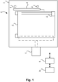
Figure 1 shows an exemplary machine comprising a process chamber and a number of sensors and actuators controlled by a PLC. -
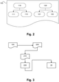
Figure 2 shows schematically a data section according to a preferred embodiment of the invention. -
Figure 3 shows schematically the process of creating a PC program using a header file and a PC program template according to a preferred embodiment of the invention. -
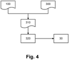
Figure 4 shows schematically the process of creating a PLC program using a header file and a PLC main program file according to a preferred embodiment of the invention. -
Figure 1 schematically shows a machine 10 which can be part of an automated cleaning and inspection system for substrate carriers (e.g., semiconductor wafer carriers, flat panel display carriers, reticle carriers, and other carriers for electronic device manufacture) used in a manufacturing process. The machine 10 comprises aprocess chamber 11 having adoor 12 and anactuator 13 configured here as a pneumatic cylinder for opening and closing the door. Twosensors 14 are provided for detecting the actuator's position to determine whether thedoor 12 is open or closed. - In the
process chamber 12, there is provided aheater 15 to heat the chamber up to a desired temperature and a rotatable plate being rotated by anelectromotor 17 with a desired speed. - The
sensors 14 andactuators PLC 30 for controlling the process. ThePLC 30 is in turn connected with aPC 20 for controlling the PLC, e.g. sending commands to and retrieving data from the PLC. -
Figure 2 schematically shows adata section 100 of a PLC program with internal blocks for indicating different services. Preferably, the data section is a header of the PLC program. Thus, the data can be read-out in a reliable and straightforward way. - As explained, the services exposed by the PLC can comprise at least one service for writing data to the PLC and/or at least one service for reading data from the PLC. Thus, practically, the data section includes one section or block 110 for the services for writing data to the PLC ("CONTROL") and one
block 120 for the services for reading data from the PLC ("INFO"). - Likewise, block 110 can be divided into two
sub-blocks sub-block 111 possible commands to the PLC, i.e. incoming data from the PC to start an action of the equipment (e.g. open/close a door, start/stop a process), can be indicated, and insub-block 112 possible writable parameters, i.e. incoming data from the PC to set the parameters related to the machine, can be indicated. - Essentially, there are two types of parameters: equipment related parameters wherein a specific equipment component is related to the command (e.g. desired speed for "Rotate Table" command), and process related parameters wherein constraints of certain process (e.g. desired temperature for "Run Process" command) are related to the command.
- Block 120 can be divided into two
sub-blocks sub-block 121 possible readable process results, i.e. outgoing data sent to the PC to report the result of the process (e.g. measured average/min/max temperature of the "Run Process" command, and the evaluation of the result according to the parameter "Desired Temperature"), can be indicated, and insub-block 122 possible readable equipment status data, i.e. outgoing data sent to the PC to report the equipment status (e.g. door open/close status) and equipment fault status (if there is any) can be indicated. - In the given example of
figure 1 : - PC can request PLC to OPEN or CLOSE the chamber (2 commands)
- PC is informed of the status of the door being either OPEN or CLOSED (2 equipment status)
- PC can request PLC to start a process (1 command) with desired temperature and electromotor speed (2 command parameters)
- PC is informed of the min/max/average temperature during the process when the process is finished (1 process result)
- A preferred header relating to this example is shown in the appendix. The header file is designed manually according to the desired equipment functionalities. It provides the interface and fully specifies all capabilities of the controlled PLC equipment to the PC program.
- On the one hand, this header file is used to create a PC program as shown in
figure 3 . On the other hand, this header file is also used to create a PLC program as shown infigure 4 . - Referring now to
figure 3 , theheader file 100 is used together with aPC program template 200 to generate a PCprogram source code 210. The PCprogram source code 210 can be compiled to create aPC program 220 which can be run on thePC 20 to control thePLC 30. Preferably, thePC program 220 is configured to show a graphical user interface when run on thePC 20. - Referring now to
figure 4 , theheader file 100 is also used together with a corresponding PLCprogram source code 300 to generate a PLCprogram source code 310. The PLCprogram source code 310 can be compiled to create aPLC program 320 which is transferred to thePLC 30 and run to control the process and simultaneously expose the services declared in theheader file 100 to be connected to by the PC program. - Using the PC program the user:
- can request PLC to OPEN or CLOSE the chamber
- is informed of the status of the door being either OPEN or CLOSED
- can request PLC to start a process with desired temperature and electromotor speed
- is informed of the min/max/average temperature during the process after the process is finished.
- It should be understood that the foregoing description is only illustrative of the aspects of the disclosed embodiment. Various alternatives and modifications can be devised by those skilled in the art without departing from the aspects of the disclosed embodiment. Accordingly, the aspects of the disclosed embodiment are intended to embrace all such alternatives, modifications and variances that fall within the scope of the appended claims. Further, the mere fact that different features are recited in mutually different dependent or independent claims does not indicate that a combination of these features cannot be advantageously used, such a combination remaining within the scope of the aspects of the invention.
-
 typedef struct
 {
       CONTROL_INTERFACE tControl; // control of slave (PLC) from master (PC)
       INFO_INTERFACE tlnfo; // info back from slave (PLC) to master (PC)
 } PLC_INTERFACE;

 typedef struct
 {
       EQUIPMENT_STATUS tStatus;
       PROCESS_RESULT tResult;
 } INFO_INTERFACE;

 typedef struct
 {
       BOOL bProcessChamberClosed; // cylinder position sensor (Digital Input)
       BOOL bProcessChamberOpen; // cylinder position sensor (Digital Input)
       INT16 iMotorPosition; // motor position (Analog Input)
 } EQUIPMENT_STATUS;

 typedef struct
 {
       REAL rMinTemperatureDuringProcess; // min temperature during process
       REAL rMaxTemperatureDuringProcess; // max temp during process
       REAL rAverageTemperatureDuringProcess; // average temp during process
 } PROCESS_RESULT;

 typedef struct
 {
       COMMAND tCommand;
       PARAMETERS tParameters;
 } CONTROL_INTERFACE;

       typedef struct
 {
       BOOL bOpenProcessChamber; // command to open the process chamber
       BOOL bCloseProcessChamber; // command to close the process chamber
       BOOL bRunProcess; // command to start a process
 } COMMAND;
 typedef struct
{
       REAL rTargetProcessTemperature; // target temperature during process
       REAL rTargetMotorSpeed; // target motor speed during process
 } PARAMETERS
 public class PLC_INTERFACE : PlcMember
 {
       public override void SetValue(string memberName, dynamic value)
       {
              switch(memberName)
              {
                      case "tControl":
                              tControl = InternaISetValue(memberName, value, tControl);
                      break;
                      case "tlnfo":
                              tlnfo = InternaISetValue(memberName, value, tlnfo);
                      break;
              }
       }
       public override dynamic GetValue(string memberName)
       {
              switch(memberName)
              {
                      case "tControl":
                              return tControl;
                      case "tlnfo":
                              return tlnfo;
              }
               return null;
       }
       public override T GetValue<T>(string memberName)
       {
              switch(memberName)
               {
                      case "tControl":
                              return (T)(object)tControl;
                      case "tlnfo":
                              return (T)(object)tlnfo;
              }
       return default(T);
       }
       public CONTROL_INTERFACE tControl = new CONTROL_INTERFACE(); // control of
 slave (PLC) from master (PC)
       public INFO_INTERFACE tlnfo = new INFO_INTERFACE(); // info back from slave
 (PLC) to master (PC)
 }
       public class INFO_INTERFACE : PlcMember
 {
       public override void SetValue(string memberName, dynamic value)
       {
              switch(memberName)
              {
                      case "tStatus":
                              tStatus = InternaISetValue(memberName, value, tStatus);
                      break;
                      case "tResult":
                              tResult = InternaISetValue(memberName, value, tResult);
                      break;
              }
       }
       public override dynamic GetValue(string memberName)
       {
              switch(memberName)
               {
                      case "tStatus":
                              return tStatus;
                      case "tResult":
                              return tResult;
              }
               return null;
       }
       public override T GetValue<T>(string memberName)
       {
              switch(memberName)
              {
                      case "tStatus":
                              return (T)(object)tStatus;
                      case "tResult":
                              return (T)(object)tResult;
              }
               return default(T);
       }
       public EQUIPMENT_STATUS tStatus = new EQUIPMENT_STATUS();
       public PROCESS_RESULT tResult = new PROCESS_RESULT();
 }
EQUIPMENT_STATUS and PROCESS_RESULT have the similar style, but are not shown here
       public class CONTROL_INTERFACE : PlcMember
 {
       public override void SetValue(string memberName, dynamic value)
       {
              switch(memberName)
              {
                      case "tCommand":
                              tCommand = InternaISetValue(memberName, value,
                      tCommand);
                      break;
                      case "tParameters":
                              tParameters = InternaISetValue(memberName, value,
                      tParameters);
                      break;
              }
       }
       public override dynamic GetValue(string memberName)
       {
              switch(memberName)
              {
                      case "tCommand":
                              return tCommand;
                      case "tParameters":
                              return tParameters;
              }
               return null;
       }
       public override T GetValue<T>(string memberName)
       {
              switch(memberName)
               {
                      case "tCommand":
                              return (T)(object)tCommand;
                      case "tParameters":
                              return (T)(object)tParameters;
              }
               return default(T);
       }
       public COMMAND tCommand = new COMMANDO;
       public PARAMETERS tParameters = new PARAMETERS();
 }
COMMAND and PARAMETERS have the similar style, but are not shown here.
Claims (13)
- A method for automatically creating a PC program (220) for controlling a PLC (30),characterized in that a source code (210) of the PC program is automatically generated using data included in a data section (100) of a source code (310) of a PLC program and a PC program template (200),the data section (100) including data indicating services to be exposed by the PLC (30) when running the PLC program,wherein the data section (100) serves as a common source code portion for both the PC program (220) and the PLC program.
- A method for controlling a PLC (30),
wherein the PLC (30) is controlled using the PC program (220) generated according to claim 1. - The method according to claim 1 or 2, wherein the PC program template (200) is a text template.
- The method according to any one of the preceding claims, wherein the data section (100) is a header of the source code (310) of the PLC program.
- The method according to any one of the preceding claims, wherein the source code (310) of the PLC program is a high-level programming language.
- The method according to any one of the preceding claims, wherein the PC program (220) is configured to show a graphical user interface when run on a PC (20).
- The method according to any one of the preceding claims, wherein the services to be exposed by the PLC (30) comprise at least one service for writing data to the PLC and/or at least one service for reading data from the PLC.
- The method according to claim 7, when dependent upon claim 2, wherein controlling the PLC (30) using the PC program (220) comprises receiving information from the PLC and/or sending commands to the PLC.
- The method according to claim 6 or 7, when dependent upon claim 2, wherein controlling the PLC (30) using the PC program (220) comprises writing values to the PLC and/or reading values from the PLC.
- The method according to any one of the preceding claims, wherein the services are exposed by the PLC (30) using a server running on the PLC (30).
- The method according to any one of the preceding claims, wherein the PLC (30) is running the PLC program.
- A computer program with a program code for causing a computer to perform a method according to any one of claims 1 to 11, when executed on the computer.
- A machine-readable storage medium having stored thereon a computer program according to claim 12.
Priority Applications (9)
| Application Number | Priority Date | Filing Date | Title |
|---|---|---|---|
| EP17174804.9A EP3413147B1 (en) | 2017-06-07 | 2017-06-07 | Method for controlling a plc using a pc program |
| JP2019568070A JP2020523689A (en) | 2017-06-07 | 2018-06-06 | Method of controlling PLC using PC program |
| PCT/EP2018/064936 WO2018224568A1 (en) | 2017-06-07 | 2018-06-06 | Method for controlling a plc using a pc program |
| CN201880037824.2A CN110914768B (en) | 2017-06-07 | 2018-06-06 | Method for controlling PLC using PC program |
| KR1020207000282A KR102560634B1 (en) | 2017-06-07 | 2018-06-06 | How to control a PLC using a PC program |
| US16/619,020 US11137735B2 (en) | 2017-06-07 | 2018-06-06 | Method for controlling a PLC using a PC program |
| TW107119731A TWI794241B (en) | 2017-06-07 | 2018-06-07 | Method for automatically creating a pc program, method for controlling a plc using the pc program, computer and computer program for performing the pc program, and machine-readable storage medium storing the pc program |
| US17/494,748 US11726445B2 (en) | 2017-06-07 | 2021-10-05 | Method for controlling a PLC using a PC program |
| US18/448,707 US20230384753A1 (en) | 2017-06-07 | 2023-08-11 | Method for controlling a plc using a pc program |
Applications Claiming Priority (1)
| Application Number | Priority Date | Filing Date | Title |
|---|---|---|---|
| EP17174804.9A EP3413147B1 (en) | 2017-06-07 | 2017-06-07 | Method for controlling a plc using a pc program |
Publications (2)
| Publication Number | Publication Date |
|---|---|
| EP3413147A1 EP3413147A1 (en) | 2018-12-12 |
| EP3413147B1 true EP3413147B1 (en) | 2022-03-23 |
Family
ID=59030826
Family Applications (1)
| Application Number | Title | Priority Date | Filing Date |
|---|---|---|---|
| EP17174804.9A Active EP3413147B1 (en) | 2017-06-07 | 2017-06-07 | Method for controlling a plc using a pc program |
Country Status (7)
| Country | Link |
|---|---|
| US (3) | US11137735B2 (en) |
| EP (1) | EP3413147B1 (en) |
| JP (1) | JP2020523689A (en) |
| KR (1) | KR102560634B1 (en) |
| CN (1) | CN110914768B (en) |
| TW (1) | TWI794241B (en) |
| WO (1) | WO2018224568A1 (en) |
Families Citing this family (3)
| Publication number | Priority date | Publication date | Assignee | Title |
|---|---|---|---|---|
| CN111475159B (en) * | 2020-03-20 | 2023-03-14 | 吉利汽车研究院(宁波)有限公司 | Method, device and storage medium for automatically generating program |
| CN111813041B (en) * | 2020-06-06 | 2021-05-07 | 杭州智尔科技有限公司 | Programmable logic controller based on computer programming language and implementation method |
| CN111857028B (en) * | 2020-06-24 | 2022-05-27 | 广州明珞汽车装备有限公司 | PLC program generation method, system, equipment and storage medium |
Family Cites Families (21)
| Publication number | Priority date | Publication date | Assignee | Title |
|---|---|---|---|---|
| JP2004164605A (en) * | 2003-09-16 | 2004-06-10 | Omron Corp | Sensor |
| JP4952401B2 (en) | 2007-06-29 | 2012-06-13 | 株式会社ジェイテクト | PLC |
| US7894460B2 (en) * | 2007-07-26 | 2011-02-22 | Air Liquide Large Industries U.S. Lp | Programmable logic controller protocol converter |
| JP4776602B2 (en) * | 2007-09-18 | 2011-09-21 | 株式会社日立製作所 | Programming device for controller, controller and controller management system |
| CN100514234C (en) * | 2007-12-28 | 2009-07-15 | 哈尔滨工业大学 | Open type numerical control system based on PC |
| CN101576820A (en) * | 2009-06-11 | 2009-11-11 | 大连理工计算机控制工程有限公司 | Method for realizing IEC61131-3 standard function block by software |
| EP2490086B1 (en) * | 2011-02-16 | 2013-10-02 | Siemens Aktiengesellschaft | Method for operating an automation system and computer program operating by the method |
| CN102681893B (en) * | 2011-03-09 | 2016-06-29 | 腾讯科技(深圳)有限公司 | The cross-platform implementation method of executable program and mobile terminal |
| US8798775B2 (en) * | 2011-06-28 | 2014-08-05 | Rockwell Automation Technologies, Inc. | Binding graphic elements to controller data |
| EP2729855A1 (en) * | 2011-07-06 | 2014-05-14 | Abb Ag | Method and device for the programming and configuration of a programmable logic controller |
| US9630228B2 (en) * | 2012-01-19 | 2017-04-25 | Primetals Technologies USA LLC | Dual cascade control system for a long rolling mill |
| US20140096860A1 (en) | 2012-10-09 | 2014-04-10 | Tai-Her Yang | Pipe Member Equipped With Heat Insulation Core Pipeline, Auxiliary Heat Conduction Structure And U-Shaped Annularly-Distributed Pipeline |
| TWI489232B (en) | 2012-11-14 | 2015-06-21 | Inst Information Industry | Remote monitoring systems and related methods and recording mediums thereof |
| JP6119452B2 (en) * | 2013-06-21 | 2017-04-26 | 富士電機株式会社 | Programmable controller system, its support device, programmable controller, program |
| US10162328B2 (en) * | 2014-03-14 | 2018-12-25 | Omron Corporation | Controller and control system |
| JP6340886B2 (en) * | 2014-04-10 | 2018-06-13 | 株式会社ジェイテクト | Program creation support apparatus for programmable logic controller and program creation support method for programmable logic controller |
| CN105740120B (en) * | 2014-12-11 | 2018-08-17 | 中国科学院软件研究所 | The monitoring in real time of software running process based on shared drive and control method and system |
| KR101886985B1 (en) * | 2014-12-15 | 2018-08-08 | 미쓰비시덴키 가부시키가이샤 | Information system construction support tool and information system construction support program |
| CN105137800A (en) * | 2015-09-11 | 2015-12-09 | 浙江中烟工业有限责任公司 | PLC cooperative control device based on SOPC technology |
| WO2017123367A1 (en) * | 2016-01-11 | 2017-07-20 | Siemens Aktiengesellschaft | Program randomization for cyber-attack resilient control in programmable logic controllers |
| CN105739481B (en) * | 2016-01-29 | 2019-03-19 | 软控股份有限公司 | The test method of industrial control software, apparatus and system |
-
2017
- 2017-06-07 EP EP17174804.9A patent/EP3413147B1/en active Active
-
2018
- 2018-06-06 KR KR1020207000282A patent/KR102560634B1/en active IP Right Grant
- 2018-06-06 CN CN201880037824.2A patent/CN110914768B/en active Active
- 2018-06-06 WO PCT/EP2018/064936 patent/WO2018224568A1/en active Application Filing
- 2018-06-06 US US16/619,020 patent/US11137735B2/en active Active
- 2018-06-06 JP JP2019568070A patent/JP2020523689A/en active Pending
- 2018-06-07 TW TW107119731A patent/TWI794241B/en active
-
2021
- 2021-10-05 US US17/494,748 patent/US11726445B2/en active Active
-
2023
- 2023-08-11 US US18/448,707 patent/US20230384753A1/en active Pending
Non-Patent Citations (1)
| Title |
|---|
| None * |
Also Published As
| Publication number | Publication date |
|---|---|
| TWI794241B (en) | 2023-03-01 |
| CN110914768A (en) | 2020-03-24 |
| US11726445B2 (en) | 2023-08-15 |
| US20220107617A1 (en) | 2022-04-07 |
| US11137735B2 (en) | 2021-10-05 |
| EP3413147A1 (en) | 2018-12-12 |
| US20200174438A1 (en) | 2020-06-04 |
| KR20200015712A (en) | 2020-02-12 |
| WO2018224568A1 (en) | 2018-12-13 |
| KR102560634B1 (en) | 2023-07-28 |
| JP2020523689A (en) | 2020-08-06 |
| TW201921199A (en) | 2019-06-01 |
| CN110914768B (en) | 2023-06-30 |
| US20230384753A1 (en) | 2023-11-30 |
Similar Documents
| Publication | Publication Date | Title |
|---|---|---|
| US11726445B2 (en) | Method for controlling a PLC using a PC program | |
| JP6548807B2 (en) | Method and system for process control of a plant in an OPC UA based machine to machine network | |
| US8060872B2 (en) | Method for transmitting a software code from a control unit to a field device of process automation technology | |
| EP2530546B1 (en) | Systems and methods for foundation fieldbus alerts | |
| US8832237B2 (en) | Method for offline servicing of a field device of automation technology | |
| US9760076B2 (en) | Method, control device and control system for the control of an automation system | |
| CN108009081B (en) | Engineering design tool cooperation device and engineering design tool cooperation method | |
| EP2357541B1 (en) | Macro function block for encapsulating device-level embedded logic | |
| EP3002649B1 (en) | Industrial simulation using redirected i/o module configurations | |
| US10805116B2 (en) | Gateway and method for connecting a data source system to an IT system | |
| CA2858054A1 (en) | Systems and methods for batch device commissioning and decommissioning | |
| JP4934041B2 (en) | Method for operating automation device and device, programming system and program for implementing method for operating automation device | |
| CN109074065B (en) | Device and method for adapting a numerical control device to a machine to be controlled, and numerical control device | |
| EP2691822A1 (en) | Method for managing process automation control and associated system | |
| CN110968051A (en) | Method and engineering system for planning an automation system | |
| JP2010519615A (en) | Method for replacement of structural components of automation systems | |
| US11651006B2 (en) | Method of visualizing screen content on a data visualization system, and data visualization system for visualizing screen content | |
| WO2018158171A1 (en) | Ensuring interface conformity in a modular process control system | |
| JP2023526182A (en) | Method for programming equipment controls | |
| US20220011735A1 (en) | Support apparatus, non-transitory computer readable medium, and control apparatus | |
| Pezzetti et al. | Real‐Time Implementation | |
| JP2009187255A (en) | Multiproduct manufacturing machine system |
Legal Events
| Date | Code | Title | Description |
|---|---|---|---|
| PUAI | Public reference made under article 153(3) epc to a published international application that has entered the european phase |
Free format text: ORIGINAL CODE: 0009012 |
|
| STAA | Information on the status of an ep patent application or granted ep patent |
Free format text: STATUS: THE APPLICATION HAS BEEN PUBLISHED |
|
| AK | Designated contracting states |
Kind code of ref document: A1 Designated state(s): AL AT BE BG CH CY CZ DE DK EE ES FI FR GB GR HR HU IE IS IT LI LT LU LV MC MK MT NL NO PL PT RO RS SE SI SK SM TR |
|
| AX | Request for extension of the european patent |
Extension state: BA ME |
|
| STAA | Information on the status of an ep patent application or granted ep patent |
Free format text: STATUS: REQUEST FOR EXAMINATION WAS MADE |
|
| 17P | Request for examination filed |
Effective date: 20190612 |
|
| RBV | Designated contracting states (corrected) |
Designated state(s): AL AT BE BG CH CY CZ DE DK EE ES FI FR GB GR HR HU IE IS IT LI LT LU LV MC MK MT NL NO PL PT RO RS SE SI SK SM TR |
|
| RAP1 | Party data changed (applicant data changed or rights of an application transferred) |
Owner name: BROOKS AUTOMATION (GERMANY) GMBH |
|
| STAA | Information on the status of an ep patent application or granted ep patent |
Free format text: STATUS: EXAMINATION IS IN PROGRESS |
|
| STAA | Information on the status of an ep patent application or granted ep patent |
Free format text: STATUS: EXAMINATION IS IN PROGRESS |
|
| 17Q | First examination report despatched |
Effective date: 20201125 |
|
| GRAP | Despatch of communication of intention to grant a patent |
Free format text: ORIGINAL CODE: EPIDOSNIGR1 |
|
| STAA | Information on the status of an ep patent application or granted ep patent |
Free format text: STATUS: GRANT OF PATENT IS INTENDED |
|
| INTG | Intention to grant announced |
Effective date: 20210716 |
|
| GRAJ | Information related to disapproval of communication of intention to grant by the applicant or resumption of examination proceedings by the epo deleted |
Free format text: ORIGINAL CODE: EPIDOSDIGR1 |
|
| STAA | Information on the status of an ep patent application or granted ep patent |
Free format text: STATUS: EXAMINATION IS IN PROGRESS |
|
| REG | Reference to a national code |
Ref country code: DE Ref legal event code: R079 Ref document number: 602017054850 Country of ref document: DE Free format text: PREVIOUS MAIN CLASS: G05B0019042000 Ipc: G06F0008330000 |
|
| GRAP | Despatch of communication of intention to grant a patent |
Free format text: ORIGINAL CODE: EPIDOSNIGR1 |
|
| STAA | Information on the status of an ep patent application or granted ep patent |
Free format text: STATUS: GRANT OF PATENT IS INTENDED |
|
| INTC | Intention to grant announced (deleted) | ||
| RAP3 | Party data changed (applicant data changed or rights of an application transferred) |
Owner name: BROOKS AUTOMATION (GERMANY) GMBH |
|
| RIC1 | Information provided on ipc code assigned before grant |
Ipc: G05B 19/05 20060101ALI20210928BHEP Ipc: G05B 19/042 20060101ALI20210928BHEP Ipc: G06F 8/38 20180101ALI20210928BHEP Ipc: G06F 8/34 20180101ALI20210928BHEP Ipc: G06F 8/33 20180101AFI20210928BHEP |
|
| INTG | Intention to grant announced |
Effective date: 20211013 |
|
| GRAS | Grant fee paid |
Free format text: ORIGINAL CODE: EPIDOSNIGR3 |
|
| GRAA | (expected) grant |
Free format text: ORIGINAL CODE: 0009210 |
|
| STAA | Information on the status of an ep patent application or granted ep patent |
Free format text: STATUS: THE PATENT HAS BEEN GRANTED |
|
| AK | Designated contracting states |
Kind code of ref document: B1 Designated state(s): AL AT BE BG CH CY CZ DE DK EE ES FI FR GB GR HR HU IE IS IT LI LT LU LV MC MK MT NL NO PL PT RO RS SE SI SK SM TR |
|
| REG | Reference to a national code |
Ref country code: GB Ref legal event code: FG4D |
|
| REG | Reference to a national code |
Ref country code: CH Ref legal event code: EP |
|
| REG | Reference to a national code |
Ref country code: IE Ref legal event code: FG4D |
|
| REG | Reference to a national code |
Ref country code: DE Ref legal event code: R096 Ref document number: 602017054850 Country of ref document: DE |
|
| REG | Reference to a national code |
Ref country code: AT Ref legal event code: REF Ref document number: 1477922 Country of ref document: AT Kind code of ref document: T Effective date: 20220415 |
|
| REG | Reference to a national code |
Ref country code: NL Ref legal event code: FP |
|
| REG | Reference to a national code |
Ref country code: LT Ref legal event code: MG9D |
|
| PG25 | Lapsed in a contracting state [announced via postgrant information from national office to epo] |
Ref country code: SE Free format text: LAPSE BECAUSE OF FAILURE TO SUBMIT A TRANSLATION OF THE DESCRIPTION OR TO PAY THE FEE WITHIN THE PRESCRIBED TIME-LIMIT Effective date: 20220323 Ref country code: RS Free format text: LAPSE BECAUSE OF FAILURE TO SUBMIT A TRANSLATION OF THE DESCRIPTION OR TO PAY THE FEE WITHIN THE PRESCRIBED TIME-LIMIT Effective date: 20220323 Ref country code: NO Free format text: LAPSE BECAUSE OF FAILURE TO SUBMIT A TRANSLATION OF THE DESCRIPTION OR TO PAY THE FEE WITHIN THE PRESCRIBED TIME-LIMIT Effective date: 20220623 Ref country code: LT Free format text: LAPSE BECAUSE OF FAILURE TO SUBMIT A TRANSLATION OF THE DESCRIPTION OR TO PAY THE FEE WITHIN THE PRESCRIBED TIME-LIMIT Effective date: 20220323 Ref country code: HR Free format text: LAPSE BECAUSE OF FAILURE TO SUBMIT A TRANSLATION OF THE DESCRIPTION OR TO PAY THE FEE WITHIN THE PRESCRIBED TIME-LIMIT Effective date: 20220323 Ref country code: BG Free format text: LAPSE BECAUSE OF FAILURE TO SUBMIT A TRANSLATION OF THE DESCRIPTION OR TO PAY THE FEE WITHIN THE PRESCRIBED TIME-LIMIT Effective date: 20220623 |
|
| REG | Reference to a national code |
Ref country code: AT Ref legal event code: MK05 Ref document number: 1477922 Country of ref document: AT Kind code of ref document: T Effective date: 20220323 |
|
| PG25 | Lapsed in a contracting state [announced via postgrant information from national office to epo] |
Ref country code: LV Free format text: LAPSE BECAUSE OF FAILURE TO SUBMIT A TRANSLATION OF THE DESCRIPTION OR TO PAY THE FEE WITHIN THE PRESCRIBED TIME-LIMIT Effective date: 20220323 Ref country code: GR Free format text: LAPSE BECAUSE OF FAILURE TO SUBMIT A TRANSLATION OF THE DESCRIPTION OR TO PAY THE FEE WITHIN THE PRESCRIBED TIME-LIMIT Effective date: 20220624 Ref country code: FI Free format text: LAPSE BECAUSE OF FAILURE TO SUBMIT A TRANSLATION OF THE DESCRIPTION OR TO PAY THE FEE WITHIN THE PRESCRIBED TIME-LIMIT Effective date: 20220323 |
|
| PG25 | Lapsed in a contracting state [announced via postgrant information from national office to epo] |
Ref country code: SM Free format text: LAPSE BECAUSE OF FAILURE TO SUBMIT A TRANSLATION OF THE DESCRIPTION OR TO PAY THE FEE WITHIN THE PRESCRIBED TIME-LIMIT Effective date: 20220323 Ref country code: SK Free format text: LAPSE BECAUSE OF FAILURE TO SUBMIT A TRANSLATION OF THE DESCRIPTION OR TO PAY THE FEE WITHIN THE PRESCRIBED TIME-LIMIT Effective date: 20220323 Ref country code: RO Free format text: LAPSE BECAUSE OF FAILURE TO SUBMIT A TRANSLATION OF THE DESCRIPTION OR TO PAY THE FEE WITHIN THE PRESCRIBED TIME-LIMIT Effective date: 20220323 Ref country code: PT Free format text: LAPSE BECAUSE OF FAILURE TO SUBMIT A TRANSLATION OF THE DESCRIPTION OR TO PAY THE FEE WITHIN THE PRESCRIBED TIME-LIMIT Effective date: 20220725 Ref country code: ES Free format text: LAPSE BECAUSE OF FAILURE TO SUBMIT A TRANSLATION OF THE DESCRIPTION OR TO PAY THE FEE WITHIN THE PRESCRIBED TIME-LIMIT Effective date: 20220323 Ref country code: EE Free format text: LAPSE BECAUSE OF FAILURE TO SUBMIT A TRANSLATION OF THE DESCRIPTION OR TO PAY THE FEE WITHIN THE PRESCRIBED TIME-LIMIT Effective date: 20220323 Ref country code: CZ Free format text: LAPSE BECAUSE OF FAILURE TO SUBMIT A TRANSLATION OF THE DESCRIPTION OR TO PAY THE FEE WITHIN THE PRESCRIBED TIME-LIMIT Effective date: 20220323 Ref country code: AT Free format text: LAPSE BECAUSE OF FAILURE TO SUBMIT A TRANSLATION OF THE DESCRIPTION OR TO PAY THE FEE WITHIN THE PRESCRIBED TIME-LIMIT Effective date: 20220323 |
|
| PG25 | Lapsed in a contracting state [announced via postgrant information from national office to epo] |
Ref country code: PL Free format text: LAPSE BECAUSE OF FAILURE TO SUBMIT A TRANSLATION OF THE DESCRIPTION OR TO PAY THE FEE WITHIN THE PRESCRIBED TIME-LIMIT Effective date: 20220323 Ref country code: IS Free format text: LAPSE BECAUSE OF FAILURE TO SUBMIT A TRANSLATION OF THE DESCRIPTION OR TO PAY THE FEE WITHIN THE PRESCRIBED TIME-LIMIT Effective date: 20220723 Ref country code: AL Free format text: LAPSE BECAUSE OF FAILURE TO SUBMIT A TRANSLATION OF THE DESCRIPTION OR TO PAY THE FEE WITHIN THE PRESCRIBED TIME-LIMIT Effective date: 20220323 |
|
| REG | Reference to a national code |
Ref country code: DE Ref legal event code: R097 Ref document number: 602017054850 Country of ref document: DE |
|
| PLBE | No opposition filed within time limit |
Free format text: ORIGINAL CODE: 0009261 |
|
| STAA | Information on the status of an ep patent application or granted ep patent |
Free format text: STATUS: NO OPPOSITION FILED WITHIN TIME LIMIT |
|
| PG25 | Lapsed in a contracting state [announced via postgrant information from national office to epo] |
Ref country code: MC Free format text: LAPSE BECAUSE OF FAILURE TO SUBMIT A TRANSLATION OF THE DESCRIPTION OR TO PAY THE FEE WITHIN THE PRESCRIBED TIME-LIMIT Effective date: 20220323 Ref country code: DK Free format text: LAPSE BECAUSE OF FAILURE TO SUBMIT A TRANSLATION OF THE DESCRIPTION OR TO PAY THE FEE WITHIN THE PRESCRIBED TIME-LIMIT Effective date: 20220323 |
|
| REG | Reference to a national code |
Ref country code: BE Ref legal event code: MM Effective date: 20220630 |
|
| 26N | No opposition filed |
Effective date: 20230102 |
|
| PG25 | Lapsed in a contracting state [announced via postgrant information from national office to epo] |
Ref country code: LU Free format text: LAPSE BECAUSE OF NON-PAYMENT OF DUE FEES Effective date: 20220607 Ref country code: IE Free format text: LAPSE BECAUSE OF NON-PAYMENT OF DUE FEES Effective date: 20220607 |
|
| PG25 | Lapsed in a contracting state [announced via postgrant information from national office to epo] |
Ref country code: SI Free format text: LAPSE BECAUSE OF FAILURE TO SUBMIT A TRANSLATION OF THE DESCRIPTION OR TO PAY THE FEE WITHIN THE PRESCRIBED TIME-LIMIT Effective date: 20220323 Ref country code: BE Free format text: LAPSE BECAUSE OF NON-PAYMENT OF DUE FEES Effective date: 20220630 |
|
| P01 | Opt-out of the competence of the unified patent court (upc) registered |
Effective date: 20230526 |
|
| PG25 | Lapsed in a contracting state [announced via postgrant information from national office to epo] |
Ref country code: IT Free format text: LAPSE BECAUSE OF FAILURE TO SUBMIT A TRANSLATION OF THE DESCRIPTION OR TO PAY THE FEE WITHIN THE PRESCRIBED TIME-LIMIT Effective date: 20220323 |
|
| PGFP | Annual fee paid to national office [announced via postgrant information from national office to epo] |
Ref country code: NL Payment date: 20230609 Year of fee payment: 7 Ref country code: FR Payment date: 20230619 Year of fee payment: 7 Ref country code: DE Payment date: 20230620 Year of fee payment: 7 |
|
| PGFP | Annual fee paid to national office [announced via postgrant information from national office to epo] |
Ref country code: GB Payment date: 20230620 Year of fee payment: 7 Ref country code: CH Payment date: 20230702 Year of fee payment: 7 |
|
| PG25 | Lapsed in a contracting state [announced via postgrant information from national office to epo] |
Ref country code: HU Free format text: LAPSE BECAUSE OF FAILURE TO SUBMIT A TRANSLATION OF THE DESCRIPTION OR TO PAY THE FEE WITHIN THE PRESCRIBED TIME-LIMIT; INVALID AB INITIO Effective date: 20170607 |