EP3413093B1 - Verfahren zur vorbereitung und / oder durchführung einer bodenbefragung in einer region von interessen und zugehöriger apparat - Google Patents
Verfahren zur vorbereitung und / oder durchführung einer bodenbefragung in einer region von interessen und zugehöriger apparat Download PDFInfo
- Publication number
- EP3413093B1 EP3413093B1 EP18176422.6A EP18176422A EP3413093B1 EP 3413093 B1 EP3413093 B1 EP 3413093B1 EP 18176422 A EP18176422 A EP 18176422A EP 3413093 B1 EP3413093 B1 EP 3413093B1
- Authority
- EP
- European Patent Office
- Prior art keywords
- flying
- ground
- probe carrier
- flying vehicle
- carrying
- Prior art date
- Legal status (The legal status is an assumption and is not a legal conclusion. Google has not performed a legal analysis and makes no representation as to the accuracy of the status listed.)
- Active
Links
Images



Classifications
-
- G—PHYSICS
- G08—SIGNALLING
- G08B—SIGNALLING SYSTEMS, e.g. PERSONAL CALLING SYSTEMS; ORDER TELEGRAPHS; ALARM SYSTEMS
- G08B21/00—Alarms responsive to a single specified undesired or abnormal condition and not otherwise provided for
- G08B21/18—Status alarms
- G08B21/22—Status alarms responsive to presence or absence of persons
-
- G—PHYSICS
- G01—MEASURING; TESTING
- G01V—GEOPHYSICS; GRAVITATIONAL MEASUREMENTS; DETECTING MASSES OR OBJECTS; TAGS
- G01V1/00—Seismology; Seismic or acoustic prospecting or detecting
- G01V1/16—Receiving elements for seismic signals; Arrangements or adaptations of receiving elements
- G01V1/168—Deployment of receiver elements
-
- G—PHYSICS
- G01—MEASURING; TESTING
- G01V—GEOPHYSICS; GRAVITATIONAL MEASUREMENTS; DETECTING MASSES OR OBJECTS; TAGS
- G01V1/00—Seismology; Seismic or acoustic prospecting or detecting
- G01V1/02—Generating seismic energy
- G01V1/104—Generating seismic energy using explosive charges
- G01V1/13—Arrangements or disposition of charges to produce a desired pattern in space or time
-
- G—PHYSICS
- G01—MEASURING; TESTING
- G01V—GEOPHYSICS; GRAVITATIONAL MEASUREMENTS; DETECTING MASSES OR OBJECTS; TAGS
- G01V1/00—Seismology; Seismic or acoustic prospecting or detecting
- G01V1/02—Generating seismic energy
- G01V1/04—Details
- G01V1/09—Transporting arrangements, e.g. on vehicles
-
- G—PHYSICS
- G08—SIGNALLING
- G08B—SIGNALLING SYSTEMS, e.g. PERSONAL CALLING SYSTEMS; ORDER TELEGRAPHS; ALARM SYSTEMS
- G08B13/00—Burglar, theft or intruder alarms
- G08B13/18—Actuation by interference with heat, light, or radiation of shorter wavelength; Actuation by intruding sources of heat, light, or radiation of shorter wavelength
- G08B13/189—Actuation by interference with heat, light, or radiation of shorter wavelength; Actuation by intruding sources of heat, light, or radiation of shorter wavelength using passive radiation detection systems
- G08B13/194—Actuation by interference with heat, light, or radiation of shorter wavelength; Actuation by intruding sources of heat, light, or radiation of shorter wavelength using passive radiation detection systems using image scanning and comparing systems
- G08B13/196—Actuation by interference with heat, light, or radiation of shorter wavelength; Actuation by intruding sources of heat, light, or radiation of shorter wavelength using passive radiation detection systems using image scanning and comparing systems using television cameras
- G08B13/19639—Details of the system layout
- G08B13/19647—Systems specially adapted for intrusion detection in or around a vehicle
- G08B13/1965—Systems specially adapted for intrusion detection in or around a vehicle the vehicle being an aircraft
-
- G—PHYSICS
- G08—SIGNALLING
- G08B—SIGNALLING SYSTEMS, e.g. PERSONAL CALLING SYSTEMS; ORDER TELEGRAPHS; ALARM SYSTEMS
- G08B21/00—Alarms responsive to a single specified undesired or abnormal condition and not otherwise provided for
-
- G—PHYSICS
- G08—SIGNALLING
- G08B—SIGNALLING SYSTEMS, e.g. PERSONAL CALLING SYSTEMS; ORDER TELEGRAPHS; ALARM SYSTEMS
- G08B23/00—Alarms responsive to unspecified undesired or abnormal conditions
Definitions
- the present invention concerns a method of preparing and/or carrying out a ground survey in a region of interest, according to the preamble of claim 1.
- the method in particular includes dropping a plurality of probes intended to partially penetrate into a ground in a predetermined dropping area, to carry out measurements in the ground and/or generating a geophysical stimulus, in particular a seismic signal in the ground with a plurality of sources, each located in a predetermined shooting area.
- Each probe is in particular intended to form a receiver including seismic sensors to conduct a geophysical survey in a region of interest.
- the region of interest is notably a region with a difficult access.
- the region in particular comprises a high density of vegetation, such as a forest, in particular a tropical forest.
- the region may comprise rugged terrain such as hills (for example foothills), cliffs and/or mountains.
- the region may comprise dangerous to access areas, such as areas with unexploded ordinances (UXO's).
- the method can also be applied to any region of interest.
- Geophysical measurements obtained during such a survey are critical in building a sub-surface earth image representative of the particular geology in the region of interest, in particular to determine the location of potential reservoirs of oil and gas.
- Such a geophysical survey is for example conducted by placing an array of seismic sources on or into the ground in the region of interest and by deploying seismic sensors able to record reflections of seismic signals produced by the successive sources on the different layers of the earth.
- the survey generally requires implanting the sources at various locations, and partially introducing receivers in the ground, for instance along several lines or random pattern, to create a dense array of receivers.
- the quality of the image obtained after the survey is generally a function of the surface density of sources and/or of receivers.
- a significant number of receivers have to be put in place in the ground to obtain an image of good quality. This is in particular the case when a three-dimensional image is required.
- the set-up of the receivers and/or the sources in the ground is an extensive process which sometimes requires drilling the ground, and in the case of the receivers, ensuring that the coupling between the receiver and the ground is adequate.
- US2015/0053480 discloses a method in which probes are carried by a flying vehicle such as an unmanned aerial vehicle. The flying vehicle is flown above the location at which the probe should be implanted in a dropping area. Then, the probe is dropped from the flying vehicle and falls to the ground.
- a flying vehicle such as an unmanned aerial vehicle.
- the acceleration reached by the probe when it impacts the ground provides sufficient energy to at least partially penetrate the ground and provide coupling with the soil for subsequent measurements.
- the sources often comprise explosives. Human and/or animal should be prevented from entering the shooting area around the sources.
- US4621347 discloses a method for attenuating sea ice flexure noise during seismic surveys.
- One aim of the invention is to obtain a method which allows preparing and/or carrying out a ground survey in a region of interest, the method being very safe for the humans and/or animals present in the region of interest.
- the subject-matter of the invention is a method according to claim 1.
- the invention further concerns an assembly for preparing and/or carrying out a ground survey in a region of interest according to claim 12.
- a first ground survey assembly 10 comprising a plurality of probes 12 put in place by a dropping assembly 11 according to the invention is disclosed schematically in figure 1 .
- the ground survey assembly 10 is for carrying out a geophysical survey of an onshore region of interest 14 schematically shown in figure 1 .
- the assembly 10 is used in particular to collect geophysical data and measurements for determining the physical properties of the subsurface 13 located in the region of interest and/or for building an image of the geology of the subsurface 13, preferably a tridimensional image of the subsurface 13.
- the region of interest 14 is for example a region having an uneven terrain 16.
- the uneven terrain 16 in particular comprises hills, mountains, cliffs or any type of rugged terrain.
- the region of interest 14 is for example located on foothills which are difficult to access.
- the region of interest 14 further comprises vegetation 18.
- the vegetation 18 is for example a forest, in particular a tropical forest. It comprises a high density of vegetation, for example trees 20 forming a canopy 22 which covers a majority of the surface of the ground in the region of interest 14.
- the subsurface 13 located below the ground comprises layers of geological formation and potentially oil and gas reservoirs.
- the vegetation 18 defines a plurality of natural and/or artificial clearings 24.
- the vegetation 18 in the region of interest 14 also defines sky holes 26 in the canopy 22.
- the clearings 24 are spread in the region of interest 14, at a distance generally comprised between 100 m and 500 m, preferentially around 300 m, taken along the line of sight between two adjacent clearings 24.
- the clearings 24 generally have a surface area greater than 25 m 2 , at the ground level and generally greater than 900m 2 at the top of the canopy 22.
- the seismic sources 30 can be put in place in the clearings 24.
- a clearing 24 is for example defined in a OGP Standard " OGP-Helicopter Guideline for Land Seismic and Helirig operations - Report 420 version 1.1 June 2013
- Sky holes 26 are generally natural. They advantageously form a vertical "light tube" between the canopy 22 and the ground.
- the sky holes 26 have a minimal surface area greater than 1 m 2 , preferentially greater than 3 m2, and comprised for example between 3 m 2 and 20 m 2 .
- the probes 12 are able to be dropped in each sky hole 26, as will be described later.
- At least a sky hole 26 has a surface area which is smaller than the surface area of the clearings 24.
- the ground survey assembly 10 comprises a plurality of sources 30, able to generate a geophysical stimulus in the ground, in particular a seismic signal.
- the ground survey assembly 10 further comprises a plurality of probes 12 spread in the region of interest 14 to collect geophysical data arising from the seismic signal generated by the sources 30.
- the ground survey assembly 10 further comprises the dropping assembly 11 for dropping the probes 12.
- the dropping assembly 11 includes a fleet of probe carrier flying vehicles 32, able to fly above the vegetation 18 to carry each probe 12 above its point of installation, and, for each probe carrier flying vehicle 32, a launching unit 34 able to separate each probe 12 carried by the flying vehicle 32 above the ground to let the probe 12 free fall to its installation point in the ground.
- the dropping assembly 11 also comprises a safety clearance managing system 35 able to check whether the area below the flying vehicle 32 is free of human and/or animal activity and/or of civil facilities.
- Civil facilities are for example camps, houses, bridges, vehicles, roads, airstrips, water reservoirs or dams.
- the ground survey assembly 10 further comprises at least a base 36 (or secondary camp), comprising at least a collection and/or analysis unit 38 and a telecommunication system 40 able to transfer data measured by the probes 12 to the collection and/or analysis unit 38, and from the collection and/or analysis unit 38 to an external station (not shown).
- a base 36 or secondary camp
- a collection and/or analysis unit 38 and a telecommunication system 40 able to transfer data measured by the probes 12 to the collection and/or analysis unit 38, and from the collection and/or analysis unit 38 to an external station (not shown).
- the base 36 advantageously comprise a helipad, night facilities for crews, and/or antenna which collect data from small antenna located in the vicinity. It is used for management of the take-off and landing. It may be used for first aid (e.g. medevac) .
- first aid e.g. medevac
- the external station may be located at a main camp (not shown).
- the main camp advantageously comprises facilities for collecting data , as well as a main computing unit, and/or a control center.
- the ground survey assembly 10 comprises at least an additional flying vehicle 42 (shown in figure 1 ) able to fly over the vegetation to carry the sources 30 in the clearings 24.
- Each seismic source 30 is able to generate a controlled seismic energy generating a geophysical stimulus, in particular a seismic signal in the ground.
- the source 30 for example comprises an explosive, in particular dynamite, able to generate the geophysical stimulus.
- the source 30 is inserted in a hole drilled into the ground, for example at a depth comprised between 0 meter and 100 meters, preferably between 5 meters and 80 meters.
- the source 30 comprises a mechanical device such as a hammer, a vibrator...
- the density of sources 30 locations laid in the region of interest 14 is generally comprised between 10 source locations per km 2 and 100 source locations per km 2 .
- Each source location can comprise one or more source 30.
- Each source 30 is preferably arranged in a clearing 24.
- the source 30 is generally brought to the clearing 24 by the additional flying vehicle 42. It can be put in place by a unmanned ground vehicle, such as a semi automatic drilling platform.
- Each probe 12 is partially introduced in the ground to sense in particular the seismic signals resulting from interactions of the seismic stimulus generated by a source 30 with the geology of the subsurface 13.
- the density of probes 12 is comprised for example between 10 probes per km 2 and 1000 probes per km 2 , in particular between 300 probes per km 2 and 500 probes per km 2 , notably 400 probes per km 2 .
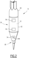
- each probe 12 has the shape of a dart.
- the probe 12 has the shape of a ball and/or a parallel pipe shape.
- the probe 12 comprises a hollow casing 50 defining a closed inner compartment 52, a sensor unit 54 comprising at least a sensor 54A received in the closed inner compartment 52 to sense at least a physical quantity, in particular a seismic signal.
- the probe 12 further comprises an emitter 56 able to collect and send data representative of the physical quantity sensed by the sensor unit 54, and at least a power source 58 able to power the sensor unit 54 and/or the emitter 56.
- the emitter 56 and the power unit 58 are also received in the closed inner compartment 52 of the hollow casing 50.
- the hollow casing 50 advantageously comprises a tapered lower end 60 to penetrate the ground, a central tubular partition 62, and a rear closing part 64 mounted at the rear of the central partition 62 opposite from the tapered lower end 60.
- the sensor 54A comprises at least one geophone, in particular three geophones and/or an accelerometer.
- the fleet of probe carrier flying vehicle 32 comprises a plurality of probe carrier flying vehicles 32, for example between 2 and 1000 probe carrier flying vehicles 32, preferably between 10 and 100 probe carrier flying vehicles 32.
- each probe carrier flying vehicle 32 comprises a platform 70 carrying the launching unit 34 and the probes 12, and at least a propeller 72, in this example a plurality of propellers 72.
- Each probe carrier flying vehicle 32 further comprises a central control unit 74 for driving the propellers 72 and directing the probe carrier flying vehicle 32 above the region of interest 14 to the dropping area in which each probe 12 has to be put in place.
- the probe carrier flying vehicle 32 further comprises a communication unit 76 for receiving guidance data from the base 36 and for sending data to the base 36 through the telecommunication system 40.
- the probe carrier flying vehicle 32 advantageously further comprises a collision detector 78, able to detect the potential occurrence of a collision with another flying unit and an autonomous redirection module 80, able to modify the trajectory of the probe carrier flying vehicle 32 when a potential collision with another flying vehicle is detected.
- the probe carrier vehicle 32 further comprises a flight insertion unit 81, able to generate an identification signal visible to other flying vehicles in the area.
- the central control unit 74 is able to receive data from the base 36 regarding the trajectory and/or the target position to be reached by the probe carrier flying vehicle 32. It is for example connected to a position detector 82 such as a ground positioning system.
- the central control unit 74 is also able to activate the propellers 72 to fly the probe carrier flying vehicle 32 to the aimed target position along the desired trajectory.
- the collision detector 78 for example comprises a radar. It is able to detect the presence of another flying vehicle in the vicinity of the probe carrier flying vehicle 32, and to detect the potential trajectory of the other flying vehicle.
- the collision detector 18 is a sound detector, an ultrasound detector, a LIDAR, or a visual system.
- the collision detector 78 is a transponder.
- the autonomous redirection module 80 is able to modify the trajectory of the probe carrier flying vehicle 32, to avoid collision with the flying vehicle detected by the collision detector 78. It is able to send a new trajectory to the central control unit 74 to implement the trajectory in case a potential collision is detected.
- the autonomous redirection module 80 is for example able to modify the altitude and/or the direction of movement of the probe carrier flying vehicle 32 to avoid collision and then to redirect the probe carrier flying vehicle 32 towards its target.
- the autonomous redirection module 80 is able to modify the trajectory according to predefined rules including priority rules for the vehicles on their way to a dropping area in comparison with vehicles being back from a dropping area.
- the launching unit 34 comprises at least a retainer 90 able to hold at least a probe 12 in the platform 70, and at least a release mechanism 92 able to release the retainer 90 to free the probe 12 from the retainer 90 and let it fall down to the dropping area.
- a volume located below the retainer 90 is advantageously open to let the probe 12 free fall from the platform 70.
- the release mechanism 92 is connected to the central control unit 74 for its actuation. It is able to release the retainer 90, without providing thrust to the probe 12.
- the probe 12 can be launched toward the ground.
- the launching impulse can be obtained by the integration of a thruster (ex: pyrotechnic, turbine, propeller%) in the probe 12, or by the use of a propulsion mechanism onboard the probe carrier flying vehicle 32 (e.g. launching actuator or the decompression of a spring).
- the impulse accelerates the fall of the probe 12 to help it penetrate further into the canopy 22 and / or the ground.
- the fall of the probe 12 can be slowed down by a braking mechanism (e.g. a parachute attached to the rear closing part 64). Slowing down the fall of the probe 12 can for instance avoid damages to the probe.
- a braking mechanism e.g. a parachute attached to the rear closing part 64. Slowing down the fall of the probe 12 can for instance avoid damages to the probe.
- the safety clearance assembly 35 comprises at least a flying presence detector 100 (here carried on each probe carrier flying vehicle 32), the flying presence detector 100 being able to detect the presence of a human and/or an animal and/or of civil facilities in the dropping area. It further comprises additional detectors such as a fixed aerial detector 101 and/or ground detectors 102 (shown in figure 1 ), to detect the presence of a human and/or an animal in the dropping area, and more generally, in the region of interest 14.
- a flying presence detector 100 here carried on each probe carrier flying vehicle 32
- the flying presence detector 100 being able to detect the presence of a human and/or an animal and/or of civil facilities in the dropping area.
- additional detectors such as a fixed aerial detector 101 and/or ground detectors 102 (shown in figure 1 ), to detect the presence of a human and/or an animal in the dropping area, and more generally, in the region of interest 14.
- the safety clearance assembly 35 further comprises a safety clearance control unit 104, here located in the base 36, to receive and analyze the data from each flying presence detector 100, from each ground detector 102, and/or from each fixed aerial detector 101.
- the safety clearance control unit 104 is able to control the activation of the launching unit 34 based on the results of the detection of a human and/or of an animal and/or of civil facilities made with each presence detector 100 and/or each ground detector 102 and/or from each fixed aerial detector 101.
- the safety clearance assembly 35 comprises a safety clearance flying vehicle 106 carrying a supplementary flying presence detector 108.
- the safety clearance assembly 35 advantageously comprises an alarm generation module 110, able to trigger an sound alarm and/or a light alarm when the flying presence detector 100 and/or the ground detector 102 and/or the fixed aerial detector 101 has detected the presence of a human and/or of an animal and/or civil facilities in the dropping area.
- the alarm generated may warn the human and/or the animal in order to make it leave the dropping area.
- the flying presence detector 100 is preferably carried by the probe carrier flying vehicle 32.
- At least a flying presence detector 100 comprises an optical detector, in particular a low light camera, an infrared camera, or a multispectral detector, in particular a high definition visual camera, or an infrared camera. Its detection span is directed downwardly, towards the ground in the dropping area.
- the flying presence detector 100 is a LIDAR.
- At least one flying presence detector 100 is able to detect an ID tag of a human and/or of an animal located in the dropping area.
- the detector 100 is for example a high definition camera or an infrared camera.
- the ground detector 102 is for example a detector able to detect a movement, heat, a particular shape (i.e. classification on image) of a human and/or of animal entering the region of interest 14, or a region close to the dropping area. It also advantageously comprises detectors able to detect ID tags of a human and/or of an animal entering a region close to the dropping area.
- the ID tag is for example a RFID tag.
- the ground detector 102 comprises a distributing acoustic sensing (DAS) sensor and/or a distributing vibrating sensing (DVS) sensor based for example on optic fibers.
- DAS distributing acoustic sensing
- DVD distributing vibrating sensing
- At least a ground detector 102 is for example located at a check point near the dropping area in the region of interest 14.
- the ground detector 102 can be set at particular point of interest to take advantage of the rough terrain like bridges, roads, mountain passes...
- At least a ground detector 102 is located along a physical border of the region of interest 14 to monitor the entrance and exit of each individual human and/or animal in the dropping area inside the region of interest 14.
- the fixed aerial detector 101 is for example a balloon equipped with a detector as defined above, in particular with at least a camera.
- the safety clearance control unit 104 is able to communicate with the control unit 74 of the probe carrier flying vehicle 32 to provide a clearance to the launching unit 34 for dropping a probe 12.
- the safety clearance control unit 104 is able to communicate with the control unit 74 of the probe carrier flying vehicle 32 to provide a prevention signal, which prevents the activation of the launching unit 34.
- the safety clearance control unit 104 is in particular able to gather all the information arising from each flying detector 100, from each ground detector 102 and from each fixed aerial detector 101. It comprises an analyzer able to generate a clearance signal in the absence of detection of presence of a human and/or of an animal and/or of civil facilities in the dropping area by all the detectors 100, 101, 102, or/and a prevention signal when any of the detectors 100, 101, 102 detects presence of a human and/or of an animal and/or of civil facilities in the dropping area.
- the safety clearance control unit 104 is able to communicate with each probe carrier flying vehicle 32 to send the clearance signal or/and the prevention signal to the central control unit 74 through the telecommunication system 40 and the communication unit 76.
- the clearance signal or/and the prevention signal is sent to each probe carrier flying vehicle 32 before the activation of a launching unit 34.
- the analyzer of the safety clearance control unit 104 is able to determine from the data received from the flying presence detector 100, from the ground detector 102 and/or from each fixed aerial detector 101 whether the detected presence is a human presence, an animal presence and/or an undefined presence, and to generate via the alarm generation module 110 a human alert signal, an animal alert signal and/or an undefined alert signal based on the detected presence.
- the safety clearance additional flying vehicle 106 is able to fly above a plurality of probe carrier flying vehicles 32 to carry out a safety clearance operation with the supplementary flying detector 108. It is also connected to the safety clearance control unit 104. It is able to scan the whole region of interest, and in particular the dropping area.
- the supplementary flying presence detector 108 is an optical detector, in particular a low light camera, an infrared camera, or a multispectral detector, in particular a high definition visual camera, an infrared camera or a LIDAR. Its detection span is directed downwardly, towards the ground in the dropping area.
- the alarm generation module 110 is able to generate an alarm, when one of the flying detectors 100 and/or of the ground detectors 102 and/or the fixed aerial detector 101 detects presence of a human and/or of an animal and/or of civil facilities in the dropping area.
- It comprises a flying alarm generator 112 carried by the probe carrier flying vehicle 32 and/or one or more ground alarm generators 114 (see figure 1 ) located in the region of interest 14.
- the flying alarm generators 112 are able to generate a directional sound and/or optical alarm, in particular a siren, and/or a light signal directed towards the ground, in particular in the dropping area.
- the ground alarm generators 114 are located at various places in and around the region of interest 14. They are able to generate a sound and/or a light alarm upon reception of the detection of a human and/or of an animal and/or of civil facilities in the region of interest 14.
- the telecommunication system 40 comprises antennas located in at least part of the clearings 24, and/or flying antennas. It is able to collect data received from the emitter 56 of each probe 12 and to convey it to the collection and analysis unit 38 at the base 34. It is also able to transfer data between the safety clearance control unit 104 at the base 36 and the communication unit 76 of each probe carrier flying vehicle 32.
- the additional flying vehicle 42 is for example an helicopter, an airship, or a balloon, which is able to carry the sources 30 towards each clearing 24.
- the airship can be an hybrid airship, etc..
- a location of a plurality of sources 30 and the location of a plurality of probes 12 in the region of interest 14 are defined respectively into artificial or natural clearings 24 of the region of interest 14 and into sky holes 26 of the region of interest 14.
- the sources 30 and the probes 12 are carried to the base 36.
- the sources 30 are then put in place in the clearings 24, advantageously by flying the additional flying vehicle 42 to each clearing 24 and by unloading each source 30 in a clearing 24.
- Each source 30 is then installed in a hole drilled in the ground.
- the installation of the probes 12 is advantageously carried out at night to facilitate the detection of human and/or animal and/or civil facilities.
- Each probe carrier flying vehicle 32 is loaded with one or more probes 12 at the base 34.
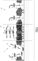
- the probe carrier flying vehicle 32 takes off and flies towards the dropping area. Upon arrival above the dropping area, just before each probe 12 is launched, the flying presence detector 100 is activated to monitor the presence of a human and/or an animal and/or of civil facilities located below the probe carrier flying vehicle 32 in the dropping area, as shown in figure 5 .
- the ground detection devices 102 and the fixed aerial detector 101 are activated to detect intrusions of human and/or animals in the region of interest 14, and more precisely in the vicinity of the dropping area and/or in the dropping area.
- the safety clearance control unit 104 gathers all the data received from the detectors 100, 101, 102 and generates a clearance signal, if no human and/or animal and/or civil facility has been detected in the dropping area by all the detectors 100, 101, 102.
- the clearance signal is then transmitted to the central control unit 74 of the probe carrier flying vehicle 32 through the telecommunication system 40 and through communication unit 76.
- the central control unit 74 then activates the release mechanism 92 to free the probe 12 from the retainer 90.
- the probe 12 falls down from the retainer 90 to the ground, and penetrates at least partially into the ground to establish coupling between the sensor unit 54 and the ground.
- the safety clearance control unit 104 generates a prevention signal if a human and/or animal and/or civil facility has been detected in the dropping area by any of the detectors 100, 101, 102.
- the prevention signal is sent to the central control unit 74 of the probe carrier flying vehicle 32 through the telecommunication system 40 and through the communication unit 76.
- the prevention signal is sent to the central control unit 74 of the probe carrier flying vehicle 32 to prevent activation of the launching unit 34.
- control unit 104 analyzes the signal produced by the presence detectors 100, 101, 102 to detect if the presence detected is a human presence, an animal presence, or an undefined presence. It triggers an alert signal, respectively a human alert signal, an animal alert signal and/or an undefined alert signal.
- the alarm generation module 110 activates.
- a visual and/or sound signal is emitted from the ground alarm generators 114, to warn the human and/or animal that a danger may occur.
- the flying alarm generator 112 is triggered to develop a directional sound and/or light alarm which is directed to the ground, to deter the human and/or animal from remaining in the dropping area.
- a safety clearance flying vehicle 106 flies, advantageously above the probe carrier flying vehicles 32, to carry out a supplementary detection with a supplementary flying human presence detector 108.
- a fleet of probe carrier flying vehicles 32 is flown simultaneously to various dropping areas in the region of interest 14, as illustrated in figure 4 .
- a first group 150 of probe carrier flying vehicles 32 simultaneously fly over the dropping area to drop a plurality of probes 12 in the dropping area. Simultaneously, a second group 152 of flying vehicles fly to and from the dropping area and a third group 154 of flying vehicles 32 land at the base 36 to let probes be loaded in the probe carrier flying vehicles 32.
- each probe carrier vehicle 32 is given a target position and a desired trajectory by a control unit at the base 36.
- the collision detector 78 and the autonomous redirection module 80 of each probe carrier flying vehicle 32 is activated to let each probe carrier flying vehicle 32 autonomously fly to the target position following the desired trajectory.
- the autonomous redirection module 80 redirects the probe carrier vehicle 32A to avoid a collision, for example by temporary changing its heading or altitude until the risk of collision is avoided.
- Each probe carrier vehicle 32 of the fleet of probe carrier vehicles 32 therefore flies in a reduced aerial space above the dropping areas and to and from the dropping areas without a risk of collision, and without the need to precisely pilot each dropping probe carrier flying vehicle 32.
- the carrying out of the ground survey then includes generating a plurality of geophysical stimuli, in particular seismic signals in the ground with at least a source 30 located in a predetermined shooting area.
- the method according to the invention advantageously comprises flying at least a presence detector 100 able to detect the presence of a human and/or of an animal and/or of civil facilities in the predetermined shooting area before activating each source 30.
- the presence detector 100 is carried on a flying vehicle 32, such as an unmanned aerial vehicle.
- the presence detector 100 Before activating the source 30, the presence detector 100, along with each ground detector 102 and/or each fixed aerial detector 101 is activated to detect presence of a human and/or of an animal and/or of civil facilities in the predetermined shooting area.
- the activation of the source 30 is controlled based on the results of the detection of a human and/or of an animal and/or of civil facilities made with the presence detector 100 and/or with the ground detector 102 and/or with the fixed aerial detector 101 as described above.
- the safety clearance control unit 104 is able to communicate with the control unit of the source 30 to provide a clearance for activating the source 30.
- the safety clearance control unit 104 is able to communicate with the control unit of the source 30 to provide a prevention signal, which prevents the activation of the source 30.
- the safety clearance control unit 104 is located at the main camp.
- the method according to the invention is extremely productive and safe. It significantly reduces the time to put in place the ground survey assembly 10 before it is ready for surveying.
- the installation of the probes 12 is easy to carry out, even for a large number of probes 12 and does not require an extensive amount of time to carry out the operation.
- a safety clearance assembly 35 comprising flying presence detectors 100 potentially in combination with ground presence detectors 102 and/or with fiwed aerial detectors is extremely efficient to detect on site the presence of human and/or animals and/or civil facilities in the region of interest 14 and more precisely, in the dropping areas or in the shooting areas. This greatly reduces and even eliminates any risk to the population and fauna located in the region of interest.
- the method does not require setting up expensive fences or safety barriers, and is much more reliable than a physical fence.
- the safety clearance control unit 104 is in addition able to gather the information arising from each the supplementary flying human presence detector 108 common to all probe carrier vehicles 32 in addition to the other collected information.
- the analyzer is hence able to generate a clearance signal for each probe carrier vehicle 32, in the absence of detection of presence of a human and/or of an animal and/or of civil facilities in the dropping area by the detector 100 of the probe carrier vehicle 32 and also by the other detector 101, 102, 108 common to at least a group or/and probe carrier vehicles 32, and a prevention signal when any of the detectors 100, 101, 102, 108 detects presence of a human and/or of an animal and/or of civil facilities in the dropping area.
Landscapes
- Physics & Mathematics (AREA)
- General Physics & Mathematics (AREA)
- Engineering & Computer Science (AREA)
- Life Sciences & Earth Sciences (AREA)
- Remote Sensing (AREA)
- Emergency Management (AREA)
- Business, Economics & Management (AREA)
- Acoustics & Sound (AREA)
- Environmental & Geological Engineering (AREA)
- Geology (AREA)
- General Life Sciences & Earth Sciences (AREA)
- Geophysics (AREA)
- Aviation & Aerospace Engineering (AREA)
- Geophysics And Detection Of Objects (AREA)
Claims (14)
- Verfahren zur Vorbereitung und/oder Durchführung einer Bodenuntersuchung in einem Gebiet von Interesse (14), umfassend:- Auslösen mindestens eines Ereignisses der Vorbereitung und/oder der Durchführung der Bodenuntersuchung in einem vorbestimmten Bereich der Region von Interesse (14);- Fliegen von mindestens einem Präsenzmelder (100), der in der Lage ist, die Anwesenheit eines Menschen und/oder eines Tieres und/oder von zivilen Einrichtungen in dem vorbestimmten Bereich des Gebiets von Interesse (14) zu erfassen;- vor dem Auslösen des Ereignisses, Erfassen der Anwesenheit eines Menschen und/oder eines Tieres und/oder von zivilen Einrichtungen in dem vorbestimmten Bereich mit dem Präsenzmelder (100);- Steuerung der Auslösung des Ereignisses auf der Grundlage der Ergebnisse der mit dem Präsenzmelder (100) durchgeführten Erfassung eines Menschen und/oder eines Tieres und/oder von zivilen Einrichtungen,dadurch gekennzeichnet, dass die Vorbereitung und/oder die Durchführung der Bodenuntersuchung das Abwerfen einer Vielzahl von Sonden (12) umfasst, die dazu bestimmt sind, teilweise in einen Boden in einem vorbestimmten Abwurfbereich einzudringen, um Messungen im Boden durchzuführen,das Verfahren umfassend die folgenden Schritte:- Fliegen von mindestens einem Sonden tragenden Flugobjekt (32) über einem Abwurfbereich am Boden, wobei das Sonden tragende Flugobjekt (32) Sonden (12) und eine Abschusseinheit (34) trägt, die in der Lage ist, jede Sonde (12) von dem Sonden tragenden Flugobjekt (32) zu trennen;Das Auslösen des Ereignisses umfasst das Aktivieren der Abschusseinheit (34), um mindestens eine der Sonden (12) von dem Sonden tragenden Flugobjekt (32) zu trennen;wobei das Verfahren ferner umfasst:- ein Fallen der Sonde (12) von dem Sonden tragenden Flugobjekt (32) auf den Boden des Abwurfbereichs;- zumindest teilweises Eindringen der Sonde (12) in den Boden des Abwurfbereichs,dass das Sonden tragende Flugobjekt (32) vorteilhafterweise den Präsenzmelder (100) trägt,das Verfahren umfasst außerdem das Fliegen eines Flugobjekts mit Sicherheitsfreigabe (106), das sich von dem oder jedem Sonden tragenden Flugobjekt (32) unterscheidet, wobei das Flugobjekt mit Sicherheitsfreigabe (106) mindestens einen zusätzlichen fliegenden Präsenzmelder (108) trägt, der in der Lage ist, die Anwesenheit eines Menschen und/oder eines Tieres und/oder von zivilen Einrichtungen in der Abwurfzone zu erfassen, wobei das Flugobjekt mit Sicherheitsfreigabe (106) vorteilhafterweise über dem oder jedem Sonden tragenden Flugobjekt (32) fliegt.
- Verfahren nach Anspruch 1, wobei der Präsenzmelder (100) einen optischen Detektor, insbesondere eine hochempfindliche Tageslichtkamera oder eine Infrarotkamera und/oder einen Multi-Spektral-Detektor umfasst.
- Verfahren nach Anspruch 1 oder 2, wobei der Präsenzdetektor (100) einen Sensor umfasst, der in der Lage ist, einen ID-Tag eines sich im Abwurfbereich befindenden Menschen und/oder Tieres zu erfassen.
- Verfahren nach einem der vorhergehenden Ansprüche, wobei das Auslösen des Ereignisses nachts erfolgt.
- Verfahren nach einem der vorhergehenden Ansprüche, umfassend das Analysieren mindestens eines von dem Präsenzmelder (100) erzeugten Signals mit einer Analyseeinheit, um mindestens ein Alarmsignal zu erzeugen, wenn die Anwesenheit eines Menschen und/oder eines Tieres und/oder von zivilen Einrichtungen erkannt wird, und/oder um mindestens ein Freigabesignal zu erzeugen, wenn kein Mensch und/oder kein Tier und/oder keine zivilen Einrichtungen erkannt werden, wobei die Analyseeinheit in der Lage ist, das Alarmsignal und/oder das Freigabesignal an eine Steuereinheit (74) zu übertragen, die das Ereignis auslöst, wobei das Alarmsignal vorteilhafterweise unter einem Alarmsignal für Menschen, einem Alarmsignal für Tiere und/oder einem undefinierten Alarmsignal ausgewählt wird.
- Verfahren nach einem der vorhergehenden Ansprüche, das die Erzeugung eines optischen oder akustischen Alarms in dem vorbestimmten Bereich umfasst, wenn die Anwesenheit eines Menschen und/oder eines Tieres durch den fliegenden Präsenzmelder (100) erfasst worden ist, wobei das Verfahren vorteilhafterweise einen fliegenden Alarmgeber (112) umfasst, der in der Lage ist, den optischen oder akustischen Alarm zu erzeugen, wenn die Anwesenheit eines Menschen und/oder eines Tieres durch den fliegenden Präsenzmelder (100) erkannt worden ist.
- Verfahren nach einem der Ansprüche 1 bis 6, umfassend das gleichzeitige Fliegen mehrerer Sonden tragender Flugobjekte (32), wobei jedes Sonden tragende Flugobjekt (32) Sonden (12) und eine Abschusseinheit (34) trägt, die in der Lage ist, jede Sonde von dem Flugobjekt über demselben Abwurfbereich am Boden zu trennen, und das Fliegen desselben Flugobjekts mit Sicherheitsfreigabe (106) für alle Sonden tragende Flugobjekte (32), die sich über demselben Abwurfbereich befinden.
- Verfahren nach einem der vorhergehenden Ansprüche, umfassend das Fliegen mindestens einer ersten Gruppe (150) von Flugobjekten der Vielzahl von Sonden tragenden Flugobjekten (32) über dem Abwurfgebiet, das gleichzeitige Fliegen mindestens eines Präsenzmelders (100) über dem Abwurfgebiet und das Abwerfen von Sonden (12) im Abwurfgebiet, gleichzeitiges Fliegen einer zweiten Gruppe (152) von Flugobjekten der Vielzahl von fliegenden Sonden tragenden Flugobjekten (32) in das und aus dem Abwurfgebiet und gleichzeitiges Landen mindestens einer dritten Gruppe (154) von Flugobjekten der Vielzahl von Sonden tragenden Flugobjekten (32) in einer Basis (36), um Sonden (12) auf die Sonden tragenden Flugobjekte (32) der dritten Gruppe (154) zu laden.
- Verfahren nach Anspruch 8, wobei jedes Sonden tragende Flugobjekt (32) einen Kollisionsdetektor (78) und ein autonomes Umlenkmodul (80) aufweist, das in der Lage ist, die Flugbahn des Sonden tragenden Flugobjekts (32) zu ändern, wenn eine mögliche Kollision mit einem anderen Sonden tragenden Flugobjekt (32) erkannt wird.
- Verfahren nach einem der Ansprüche 1 bis 9, wobei das Sonden tragende Flugobjekt (32) und/oder das Flugobjekt mit Sicherheitsfreigabe (108) unbemannte Luftfahrzeuge sind.
- Verfahren nach einem der vorhergehenden Ansprüche, wobei die Vorbereitung und/oder Durchführung der Bodenuntersuchung die Erzeugung eines geophysikalischen Stimulus, insbesondere eines seismischen Signals im Boden mit einer Quelle (30) umfasst, die sich in einem vorbestimmten Aufnahmebereich befindet, wobei das Auslösen des Ereignisses die Aktivierung der Quelle (30) zur Erzeugung des geophysikalischen Stimulus umfasst.
- Anordnung (11) zur Vorbereitung und/oder Durchführung einer Bodenvermessung in einem Gebiet von Interesse (14), umfassend:- eine Vorrichtung zum Auslösen mindestens eines Ereignisses der Vorbereitung und/oder der Durchführung der Bodenuntersuchung in einem vorbestimmten Bereich der Region von Interesse (14);- ein Flugobjekt, das mindestens einen Präsenzmelder (100) trägt, der in der Lage ist, die Anwesenheit eines Menschen und/oder eines Tieres und/oder von zivilen Einrichtungen in dem vorbestimmten Gebiet zu erkennen;- eine Steuereinheit (104), die so konfiguriert ist, dass sie das Auslösen des Ereignisses auf der Grundlage der Ergebnisse der mit dem Präsenzmelder (100) durchgeführten Erfassung eines Menschen und/oder eines Tieres und/oder von zivilen Einrichtungen steuert,die Vorbereitung und/oder die Durchführung der Bodenuntersuchung das Abwerfen einer Vielzahl von Sonden (12) umfasst, die dazu bestimmt sind, teilweise in einen Boden in einem vorbestimmten Abwurfbereich eingeführt zu werden, um Messungen im Boden vorzunehmen,die Vorrichtung zum Auslösen mindestens eines Ereignisses der Vorbereitung und/oder der Durchführung der Bodenuntersuchung mindestens ein Sonden tragendes Flugobjekt (32), das Sonden (12) trägt, und eine Abschusseinheit (34) umfasst, die in der Lage ist, jede Sonde von dem Flugobjekt über einem Abwurfbereich am Boden zu trennen, wobei das Ereignis durch Aktivierung der Abschusseinheit (34) ausgelöst wird,wobei die Baugruppe (11) außerdem ein Flugobjekt mit Sicherheitsfreigabe (106) umfasst, das sich von dem oder jedem Sonden tragenden Flugobjekt (32) unterscheidet, wobei das Flugobjekt mit Sicherheitsfreigabe (106) mindestens einen zusätzlichen fliegenden Präsenzmelder (108) trägt, der in der Lage ist, die Anwesenheit eines Menschen und/oder eines Tieres und/oder von zivilen Einrichtungen in der Abwurfzone zu erfassen.
- Anordnung (11) nach Anspruch 12, umfassend eine Vielzahl von Sonden tragenden Flugobjekten (32), von denen jedes mindestens Sonden (12) und eine Abschusseinheit (34) trägt, die in der Lage ist, jede Sonde von dem Flugobjekt über demselben Abwurfbereich am Boden zu trennen, wobei jedes Sonden tragende Flugobjekt (32) einen Präsenzmelder (100) trägt, wobei die Steuereinheit (104) die Aktivierung der Abschusseinheit (34) jedes Sonden tragenden Flugobjekts (32) der Vielzahl von Sonden tragenden Flugobjekten (32) auf der Grundlage der Ergebnisse der mit dem Präsenzmelder (100) durchgeführten Erfassung eines Menschen und/oder eines Tieres und/oder von zivilen Einrichtungen steuert,
- Anordnung (11) nach Anspruch 13, wobei die Vorbereitung und/oder Durchführung der Bodenuntersuchung die Erzeugung eines geophysikalischen Stimulus, insbesondere eines seismischen Signals im Boden, umfasst,
die Vorrichtung zum Auslösen mindestens eines Ereignisses der Vorbereitung und/oder der Durchführung der Bodenuntersuchung mindestens eine Quelle (30) umfasst, die sich in einem vorbestimmten Aufnahmebereich befindet, wobei das Auslösen des Ereignisses die Aktivierung der Quelle (30) ist, um den geophysikalischen Stimulus zu erzeugen.
Applications Claiming Priority (1)
| Application Number | Priority Date | Filing Date | Title |
|---|---|---|---|
| EP17305688 | 2017-06-08 |
Publications (2)
| Publication Number | Publication Date |
|---|---|
| EP3413093A1 EP3413093A1 (de) | 2018-12-12 |
| EP3413093B1 true EP3413093B1 (de) | 2023-08-23 |
Family
ID=59858659
Family Applications (1)
| Application Number | Title | Priority Date | Filing Date |
|---|---|---|---|
| EP18176422.6A Active EP3413093B1 (de) | 2017-06-08 | 2018-06-07 | Verfahren zur vorbereitung und / oder durchführung einer bodenbefragung in einer region von interessen und zugehöriger apparat |
Country Status (3)
| Country | Link |
|---|---|
| US (1) | US10395509B2 (de) |
| EP (1) | EP3413093B1 (de) |
| CN (1) | CN109100779B (de) |
Families Citing this family (5)
| Publication number | Priority date | Publication date | Assignee | Title |
|---|---|---|---|---|
| WO2020263194A1 (en) * | 2019-06-26 | 2020-12-30 | Orica International Pte Ltd | Deployment of quasi-planar shock wave generators in association with seismic exploration |
| CN113376621B (zh) * | 2021-05-26 | 2023-04-07 | 哈尔滨工程大学 | 一种冰基水下声源探测装置及其探测方法 |
| US20240329263A1 (en) * | 2021-07-16 | 2024-10-03 | Totalenergies Onetech | Sensor device for geophysical measurement intended to be disposed on a surface of a ground, related assembly and method for deploying and retrieving such a sensor |
| CN114162340B (zh) * | 2021-11-29 | 2024-06-04 | 浙江图盛输变电工程有限公司温州科技分公司 | 一种杆塔挂点绝对坐标采集系统 |
| SE547549C2 (en) * | 2024-04-23 | 2025-10-14 | Airforestry Ab | Method and system for harvesting a tree from air, dependent on presence of a human person at a final destination |
Family Cites Families (39)
| Publication number | Priority date | Publication date | Assignee | Title |
|---|---|---|---|---|
| US4621347A (en) | 1983-10-31 | 1986-11-04 | Chevron Research Company | Method of attenuating sea ice flexure noise during seismic surveys of permafrost regions involving a precursor aerial and/or satellite mapping step |
| US6843158B2 (en) | 2000-06-01 | 2005-01-18 | Maurice M. Garcia | Method and apparatus for detecting target objects |
| WO2004017096A2 (en) | 2002-05-02 | 2004-02-26 | Garcia Maurice M | Method and apparatus for detecting target objects |
| US7478680B2 (en) * | 2005-01-24 | 2009-01-20 | Vinayagamurthy Sridharan | Fire extinguishing by explosive pulverisation of projectile based frozen gases and compacted solid extinguishing agents |
| US20080078865A1 (en) * | 2006-09-21 | 2008-04-03 | Honeywell International Inc. | Unmanned Sensor Placement In A Cluttered Terrain |
| GB0725276D0 (en) * | 2007-12-28 | 2008-02-06 | Vibration Technology Ltd | Seismic data recording |
| EP2165603A1 (de) * | 2008-09-23 | 2010-03-24 | Koninklijke Philips Electronics N.V. | Tierangepasstes Beleuchtungsverfahren und -system |
| DE102009036809A1 (de) | 2009-08-10 | 2011-02-24 | Deutsches Zentrum für Luft- und Raumfahrt e.V. | Verfahren zur Erkennung von Tieren einschließlich Brutgelegen in landwirt-schaftlich genutzten Feldern und Wiesen sowie Vorrichtung zur Durchführung des Verfahrens |
| US8564452B2 (en) | 2010-03-19 | 2013-10-22 | Marlex Engineering Inc. | Radio-frequency identification (RFID) safety system |
| RU2615470C2 (ru) | 2012-03-26 | 2017-04-04 | Волаком Ад | Система предотвращения столкновения животных |
| CA2780249A1 (en) | 2012-06-11 | 2013-12-11 | Christina Arraya | Shofar with different noises, sounds for aircraft and aviation purposes |
| US9400338B2 (en) | 2012-09-18 | 2016-07-26 | Westerngeco L.L.C. | Seismic acquisition system-based unmanned airborne vehicle |
| US8707900B1 (en) | 2012-09-19 | 2014-04-29 | Krystalka Ronette Womble | Method and system for remote monitoring, care and maintenance of animals |
| DE102013108204A1 (de) | 2013-07-31 | 2015-02-05 | E-Volo Gmbh | Bergungsvorrichtung für die Verwendung an einem Fluggerät und Fluggerät, insbesondere Multicopter |
| US9726006B2 (en) | 2013-08-22 | 2017-08-08 | Elwha Llc | Kinetic penetrator beacons for multistatic geophysical sensing |
| US9567077B2 (en) * | 2014-02-14 | 2017-02-14 | Accenture Global Services Limited | Unmanned vehicle (UV) control system |
| CN103803091B (zh) | 2014-02-25 | 2015-10-28 | 顾天罡 | 飞机用主动式防鸟击方法及装置 |
| US9643722B1 (en) | 2014-02-28 | 2017-05-09 | Lucas J. Myslinski | Drone device security system |
| US9972055B2 (en) | 2014-02-28 | 2018-05-15 | Lucas J. Myslinski | Fact checking method and system utilizing social networking information |
| US10045523B2 (en) | 2014-04-10 | 2018-08-14 | Ninox Robotics Pty Ltd | Baiting method and apparatus for pest control |
| ES2564085B1 (es) | 2014-04-25 | 2017-10-24 | Consejo Superior De Investigaciones Científicas (Csic) | Vehículo aéreo biomimético y zoosemiótico dirigido por piloto autómático |
| WO2015188831A1 (en) | 2014-06-10 | 2015-12-17 | Aarhus Universitet | Method for removing animals from a field |
| US20160011324A1 (en) * | 2014-07-11 | 2016-01-14 | Sercel | Method For Harvesting Seismic Data And Generating Seismic Output Files |
| US20160180126A1 (en) * | 2014-10-05 | 2016-06-23 | Kashif SALEEM | Method and System for Assets Management Using Integrated Unmanned Aerial Vehicle and Radio Frequency Identification Reader |
| US9747901B1 (en) | 2015-02-27 | 2017-08-29 | Amazon Technologies, Inc. | Speech interaction for unmanned aerial vehicles |
| CN107592914B (zh) * | 2015-03-02 | 2020-03-17 | 道达尔公司 | 用于将地震波传感器耦合到地面的系统和方法 |
| JP6594640B2 (ja) | 2015-03-30 | 2019-10-23 | セコム株式会社 | 監視システム |
| KR101535401B1 (ko) | 2015-04-01 | 2015-07-08 | 오인선 | 드론방식 구명장비 투하장치 |
| JP6514973B2 (ja) | 2015-06-30 | 2019-05-15 | 株式会社トプコン | 現場管理システム、飛行検出方法およびプログラム |
| CN105015767A (zh) | 2015-07-09 | 2015-11-04 | 湖北省机电研究设计院股份公司 | 具有消防侦察功能的多旋翼无人机飞行器系统 |
| WO2017044079A1 (en) * | 2015-09-09 | 2017-03-16 | Thomson Licensing | Method and apparatus for allocation of air space for unmanned aerial vehicles |
| KR101762511B1 (ko) | 2015-11-10 | 2017-07-27 | 경희대학교 산학협력단 | 드론을 이용한 야생동물 퇴치 시스템 및 이를 이용한 퇴치 방법. |
| WO2017083282A1 (en) | 2015-11-13 | 2017-05-18 | Wal-Mart Stores, Inc. | Product delivery methods and systems utilizing portable unmanned delivery aircraft |
| KR101715209B1 (ko) | 2015-12-02 | 2017-03-22 | 한국건설기술연구원 | 드론을 이용한 매몰자의 무선신호감지를 통한 위치검출 방법 및 시스템 |
| US10040551B2 (en) | 2015-12-22 | 2018-08-07 | International Business Machines Corporation | Drone delivery of coffee based on a cognitive state of an individual |
| JP2017114270A (ja) | 2015-12-24 | 2017-06-29 | 株式会社ナカヨ | 特定ビーコン追跡機能を有する無人飛行体および追跡ビーコン発信ユニット |
| EP4095637B1 (de) * | 2016-12-12 | 2024-07-03 | Alarm.com Incorporated | Drohnenvorüberwachung |
| CN106940210A (zh) | 2017-05-08 | 2017-07-11 | 佛山市神风航空科技有限公司 | 一种环境监测无人机 |
| CN107252495A (zh) | 2017-06-28 | 2017-10-17 | 太仓迪米克斯节能服务有限公司 | 一种基于无人机的共享消毒方法及其系统 |
-
2018
- 2018-06-06 US US16/001,079 patent/US10395509B2/en active Active
- 2018-06-07 EP EP18176422.6A patent/EP3413093B1/de active Active
- 2018-06-08 CN CN201810586281.1A patent/CN109100779B/zh active Active
Also Published As
| Publication number | Publication date |
|---|---|
| US20180357885A1 (en) | 2018-12-13 |
| CN109100779A (zh) | 2018-12-28 |
| EP3413093A1 (de) | 2018-12-12 |
| US10395509B2 (en) | 2019-08-27 |
| CN109100779B (zh) | 2021-06-11 |
Similar Documents
| Publication | Publication Date | Title |
|---|---|---|
| US10395509B2 (en) | Method of preparing and/or carrying out a ground survey in a region of interest and related apparatus | |
| US11061155B2 (en) | Method of dropping a plurality of probes intended to partially penetrate into a ground using a vegetation detection, and related system | |
| US20240294254A1 (en) | Device and method for blasting avalanches | |
| US8935014B2 (en) | Method and system for deploying a surveillance network | |
| US9513371B2 (en) | Ground survey and obstacle detection system | |
| US9726006B2 (en) | Kinetic penetrator beacons for multistatic geophysical sensing | |
| US9562396B2 (en) | Kinetic penetrator with a retrieval tether | |
| US20200183029A1 (en) | A probe intended to be partially introduced into a ground from a flying vehicle, related assembly and method | |
| Kovács et al. | Landmine detection with drones | |
| EP3635441B1 (de) | Verfahren zur erfassung eines seismischen datensatzes über eine region von interesse | |
| US3474405A (en) | Method and apparatus for detecting the presence of enemy personnel in subterranean chambers | |
| US6453790B1 (en) | Munitions success information system | |
| US20240329263A1 (en) | Sensor device for geophysical measurement intended to be disposed on a surface of a ground, related assembly and method for deploying and retrieving such a sensor | |
| US20220214465A1 (en) | Tool for recovering a seismic apparatus at least partially inserted in the ground, related assembly and method | |
| WO2020115519A1 (en) | A probe intended to be partially introduced into a ground from a flying vehicle, related assembly and method | |
| UA154105U (uk) | Спосіб ведення повітряної розвідки місць розташування мін | |
| Lahti et al. | Airborne Magnetometer Survey Update at the Massachusetts Military Reservation | |
| Kholodiuk et al. | Development of a system for remote detection of explosive devices and pollution on agricultural lands |
Legal Events
| Date | Code | Title | Description |
|---|---|---|---|
| PUAI | Public reference made under article 153(3) epc to a published international application that has entered the european phase |
Free format text: ORIGINAL CODE: 0009012 |
|
| STAA | Information on the status of an ep patent application or granted ep patent |
Free format text: STATUS: REQUEST FOR EXAMINATION WAS MADE |
|
| 17P | Request for examination filed |
Effective date: 20180607 |
|
| AK | Designated contracting states |
Kind code of ref document: A1 Designated state(s): AL AT BE BG CH CY CZ DE DK EE ES FI FR GB GR HR HU IE IS IT LI LT LU LV MC MK MT NL NO PL PT RO RS SE SI SK SM TR |
|
| AX | Request for extension of the european patent |
Extension state: BA ME |
|
| RAP1 | Party data changed (applicant data changed or rights of an application transferred) |
Owner name: TOTAL SE |
|
| STAA | Information on the status of an ep patent application or granted ep patent |
Free format text: STATUS: EXAMINATION IS IN PROGRESS |
|
| 17Q | First examination report despatched |
Effective date: 20210927 |
|
| RAP1 | Party data changed (applicant data changed or rights of an application transferred) |
Owner name: TOTALENERGIES ONETECH |
|
| GRAP | Despatch of communication of intention to grant a patent |
Free format text: ORIGINAL CODE: EPIDOSNIGR1 |
|
| STAA | Information on the status of an ep patent application or granted ep patent |
Free format text: STATUS: GRANT OF PATENT IS INTENDED |
|
| RIC1 | Information provided on ipc code assigned before grant |
Ipc: G08B 13/196 20060101ALI20230227BHEP Ipc: G01V 1/16 20060101AFI20230227BHEP |
|
| INTG | Intention to grant announced |
Effective date: 20230321 |
|
| GRAS | Grant fee paid |
Free format text: ORIGINAL CODE: EPIDOSNIGR3 |
|
| GRAA | (expected) grant |
Free format text: ORIGINAL CODE: 0009210 |
|
| STAA | Information on the status of an ep patent application or granted ep patent |
Free format text: STATUS: THE PATENT HAS BEEN GRANTED |
|
| AK | Designated contracting states |
Kind code of ref document: B1 Designated state(s): AL AT BE BG CH CY CZ DE DK EE ES FI FR GB GR HR HU IE IS IT LI LT LU LV MC MK MT NL NO PL PT RO RS SE SI SK SM TR |
|
| REG | Reference to a national code |
Ref country code: GB Ref legal event code: FG4D |
|
| REG | Reference to a national code |
Ref country code: CH Ref legal event code: EP |
|
| REG | Reference to a national code |
Ref country code: IE Ref legal event code: FG4D |
|
| REG | Reference to a national code |
Ref country code: DE Ref legal event code: R096 Ref document number: 602018055809 Country of ref document: DE |
|
| REG | Reference to a national code |
Ref country code: LT Ref legal event code: MG9D |
|
| P01 | Opt-out of the competence of the unified patent court (upc) registered |
Effective date: 20231116 |
|
| REG | Reference to a national code |
Ref country code: NL Ref legal event code: MP Effective date: 20230823 |
|
| REG | Reference to a national code |
Ref country code: AT Ref legal event code: MK05 Ref document number: 1603243 Country of ref document: AT Kind code of ref document: T Effective date: 20230823 |
|
| PG25 | Lapsed in a contracting state [announced via postgrant information from national office to epo] |
Ref country code: GR Free format text: LAPSE BECAUSE OF FAILURE TO SUBMIT A TRANSLATION OF THE DESCRIPTION OR TO PAY THE FEE WITHIN THE PRESCRIBED TIME-LIMIT Effective date: 20231124 |
|
| PG25 | Lapsed in a contracting state [announced via postgrant information from national office to epo] |
Ref country code: IS Free format text: LAPSE BECAUSE OF FAILURE TO SUBMIT A TRANSLATION OF THE DESCRIPTION OR TO PAY THE FEE WITHIN THE PRESCRIBED TIME-LIMIT Effective date: 20231223 |
|
| PG25 | Lapsed in a contracting state [announced via postgrant information from national office to epo] |
Ref country code: SE Free format text: LAPSE BECAUSE OF FAILURE TO SUBMIT A TRANSLATION OF THE DESCRIPTION OR TO PAY THE FEE WITHIN THE PRESCRIBED TIME-LIMIT Effective date: 20230823 Ref country code: RS Free format text: LAPSE BECAUSE OF FAILURE TO SUBMIT A TRANSLATION OF THE DESCRIPTION OR TO PAY THE FEE WITHIN THE PRESCRIBED TIME-LIMIT Effective date: 20230823 Ref country code: PT Free format text: LAPSE BECAUSE OF FAILURE TO SUBMIT A TRANSLATION OF THE DESCRIPTION OR TO PAY THE FEE WITHIN THE PRESCRIBED TIME-LIMIT Effective date: 20231226 Ref country code: NO Free format text: LAPSE BECAUSE OF FAILURE TO SUBMIT A TRANSLATION OF THE DESCRIPTION OR TO PAY THE FEE WITHIN THE PRESCRIBED TIME-LIMIT Effective date: 20231123 Ref country code: NL Free format text: LAPSE BECAUSE OF FAILURE TO SUBMIT A TRANSLATION OF THE DESCRIPTION OR TO PAY THE FEE WITHIN THE PRESCRIBED TIME-LIMIT Effective date: 20230823 Ref country code: LV Free format text: LAPSE BECAUSE OF FAILURE TO SUBMIT A TRANSLATION OF THE DESCRIPTION OR TO PAY THE FEE WITHIN THE PRESCRIBED TIME-LIMIT Effective date: 20230823 Ref country code: LT Free format text: LAPSE BECAUSE OF FAILURE TO SUBMIT A TRANSLATION OF THE DESCRIPTION OR TO PAY THE FEE WITHIN THE PRESCRIBED TIME-LIMIT Effective date: 20230823 Ref country code: IS Free format text: LAPSE BECAUSE OF FAILURE TO SUBMIT A TRANSLATION OF THE DESCRIPTION OR TO PAY THE FEE WITHIN THE PRESCRIBED TIME-LIMIT Effective date: 20231223 Ref country code: HR Free format text: LAPSE BECAUSE OF FAILURE TO SUBMIT A TRANSLATION OF THE DESCRIPTION OR TO PAY THE FEE WITHIN THE PRESCRIBED TIME-LIMIT Effective date: 20230823 Ref country code: GR Free format text: LAPSE BECAUSE OF FAILURE TO SUBMIT A TRANSLATION OF THE DESCRIPTION OR TO PAY THE FEE WITHIN THE PRESCRIBED TIME-LIMIT Effective date: 20231124 Ref country code: FI Free format text: LAPSE BECAUSE OF FAILURE TO SUBMIT A TRANSLATION OF THE DESCRIPTION OR TO PAY THE FEE WITHIN THE PRESCRIBED TIME-LIMIT Effective date: 20230823 Ref country code: AT Free format text: LAPSE BECAUSE OF FAILURE TO SUBMIT A TRANSLATION OF THE DESCRIPTION OR TO PAY THE FEE WITHIN THE PRESCRIBED TIME-LIMIT Effective date: 20230823 |
|
| PG25 | Lapsed in a contracting state [announced via postgrant information from national office to epo] |
Ref country code: PL Free format text: LAPSE BECAUSE OF FAILURE TO SUBMIT A TRANSLATION OF THE DESCRIPTION OR TO PAY THE FEE WITHIN THE PRESCRIBED TIME-LIMIT Effective date: 20230823 |
|
| PG25 | Lapsed in a contracting state [announced via postgrant information from national office to epo] |
Ref country code: ES Free format text: LAPSE BECAUSE OF FAILURE TO SUBMIT A TRANSLATION OF THE DESCRIPTION OR TO PAY THE FEE WITHIN THE PRESCRIBED TIME-LIMIT Effective date: 20230823 |
|
| PG25 | Lapsed in a contracting state [announced via postgrant information from national office to epo] |
Ref country code: SM Free format text: LAPSE BECAUSE OF FAILURE TO SUBMIT A TRANSLATION OF THE DESCRIPTION OR TO PAY THE FEE WITHIN THE PRESCRIBED TIME-LIMIT Effective date: 20230823 Ref country code: RO Free format text: LAPSE BECAUSE OF FAILURE TO SUBMIT A TRANSLATION OF THE DESCRIPTION OR TO PAY THE FEE WITHIN THE PRESCRIBED TIME-LIMIT Effective date: 20230823 Ref country code: ES Free format text: LAPSE BECAUSE OF FAILURE TO SUBMIT A TRANSLATION OF THE DESCRIPTION OR TO PAY THE FEE WITHIN THE PRESCRIBED TIME-LIMIT Effective date: 20230823 Ref country code: EE Free format text: LAPSE BECAUSE OF FAILURE TO SUBMIT A TRANSLATION OF THE DESCRIPTION OR TO PAY THE FEE WITHIN THE PRESCRIBED TIME-LIMIT Effective date: 20230823 Ref country code: DK Free format text: LAPSE BECAUSE OF FAILURE TO SUBMIT A TRANSLATION OF THE DESCRIPTION OR TO PAY THE FEE WITHIN THE PRESCRIBED TIME-LIMIT Effective date: 20230823 Ref country code: CZ Free format text: LAPSE BECAUSE OF FAILURE TO SUBMIT A TRANSLATION OF THE DESCRIPTION OR TO PAY THE FEE WITHIN THE PRESCRIBED TIME-LIMIT Effective date: 20230823 Ref country code: SK Free format text: LAPSE BECAUSE OF FAILURE TO SUBMIT A TRANSLATION OF THE DESCRIPTION OR TO PAY THE FEE WITHIN THE PRESCRIBED TIME-LIMIT Effective date: 20230823 |
|
| REG | Reference to a national code |
Ref country code: DE Ref legal event code: R097 Ref document number: 602018055809 Country of ref document: DE |
|
| PG25 | Lapsed in a contracting state [announced via postgrant information from national office to epo] |
Ref country code: IT Free format text: LAPSE BECAUSE OF FAILURE TO SUBMIT A TRANSLATION OF THE DESCRIPTION OR TO PAY THE FEE WITHIN THE PRESCRIBED TIME-LIMIT Effective date: 20230823 |
|
| PLBE | No opposition filed within time limit |
Free format text: ORIGINAL CODE: 0009261 |
|
| STAA | Information on the status of an ep patent application or granted ep patent |
Free format text: STATUS: NO OPPOSITION FILED WITHIN TIME LIMIT |
|
| 26N | No opposition filed |
Effective date: 20240524 |
|
| PG25 | Lapsed in a contracting state [announced via postgrant information from national office to epo] |
Ref country code: SI Free format text: LAPSE BECAUSE OF FAILURE TO SUBMIT A TRANSLATION OF THE DESCRIPTION OR TO PAY THE FEE WITHIN THE PRESCRIBED TIME-LIMIT Effective date: 20230823 |
|
| PG25 | Lapsed in a contracting state [announced via postgrant information from national office to epo] |
Ref country code: BG Free format text: LAPSE BECAUSE OF FAILURE TO SUBMIT A TRANSLATION OF THE DESCRIPTION OR TO PAY THE FEE WITHIN THE PRESCRIBED TIME-LIMIT Effective date: 20230823 |
|
| PG25 | Lapsed in a contracting state [announced via postgrant information from national office to epo] |
Ref country code: BG Free format text: LAPSE BECAUSE OF FAILURE TO SUBMIT A TRANSLATION OF THE DESCRIPTION OR TO PAY THE FEE WITHIN THE PRESCRIBED TIME-LIMIT Effective date: 20230823 |
|
| REG | Reference to a national code |
Ref country code: DE Ref legal event code: R119 Ref document number: 602018055809 Country of ref document: DE |
|
| PG25 | Lapsed in a contracting state [announced via postgrant information from national office to epo] |
Ref country code: MC Free format text: LAPSE BECAUSE OF FAILURE TO SUBMIT A TRANSLATION OF THE DESCRIPTION OR TO PAY THE FEE WITHIN THE PRESCRIBED TIME-LIMIT Effective date: 20230823 |
|
| REG | Reference to a national code |
Ref country code: CH Ref legal event code: PL |
|
| PG25 | Lapsed in a contracting state [announced via postgrant information from national office to epo] |
Ref country code: LU Free format text: LAPSE BECAUSE OF NON-PAYMENT OF DUE FEES Effective date: 20240607 |
|
| PG25 | Lapsed in a contracting state [announced via postgrant information from national office to epo] |
Ref country code: DE Free format text: LAPSE BECAUSE OF NON-PAYMENT OF DUE FEES Effective date: 20250101 |
|
| PG25 | Lapsed in a contracting state [announced via postgrant information from national office to epo] |
Ref country code: IE Free format text: LAPSE BECAUSE OF NON-PAYMENT OF DUE FEES Effective date: 20240607 |
|
| PG25 | Lapsed in a contracting state [announced via postgrant information from national office to epo] |
Ref country code: BE Free format text: LAPSE BECAUSE OF NON-PAYMENT OF DUE FEES Effective date: 20240630 Ref country code: CH Free format text: LAPSE BECAUSE OF NON-PAYMENT OF DUE FEES Effective date: 20240630 |
|
| REG | Reference to a national code |
Ref country code: BE Ref legal event code: MM Effective date: 20240630 |
|
| PGFP | Annual fee paid to national office [announced via postgrant information from national office to epo] |
Ref country code: GB Payment date: 20250618 Year of fee payment: 8 |
|
| PGFP | Annual fee paid to national office [announced via postgrant information from national office to epo] |
Ref country code: FR Payment date: 20250625 Year of fee payment: 8 |
|
| PG25 | Lapsed in a contracting state [announced via postgrant information from national office to epo] |
Ref country code: CY Free format text: LAPSE BECAUSE OF FAILURE TO SUBMIT A TRANSLATION OF THE DESCRIPTION OR TO PAY THE FEE WITHIN THE PRESCRIBED TIME-LIMIT; INVALID AB INITIO Effective date: 20180607 |
|
| PG25 | Lapsed in a contracting state [announced via postgrant information from national office to epo] |
Ref country code: HU Free format text: LAPSE BECAUSE OF FAILURE TO SUBMIT A TRANSLATION OF THE DESCRIPTION OR TO PAY THE FEE WITHIN THE PRESCRIBED TIME-LIMIT; INVALID AB INITIO Effective date: 20180607 |