EP3412870A1 - Turbine blade tip comprising oblong purge holes - Google Patents
Turbine blade tip comprising oblong purge holes Download PDFInfo
- Publication number
- EP3412870A1 EP3412870A1 EP18174121.6A EP18174121A EP3412870A1 EP 3412870 A1 EP3412870 A1 EP 3412870A1 EP 18174121 A EP18174121 A EP 18174121A EP 3412870 A1 EP3412870 A1 EP 3412870A1
- Authority
- EP
- European Patent Office
- Prior art keywords
- opening
- blade
- dimension
- tip
- turbine
- Prior art date
- Legal status (The legal status is an assumption and is not a legal conclusion. Google has not performed a legal analysis and makes no representation as to the accuracy of the status listed.)
- Granted
Links
Images


Classifications
-
- F—MECHANICAL ENGINEERING; LIGHTING; HEATING; WEAPONS; BLASTING
- F01—MACHINES OR ENGINES IN GENERAL; ENGINE PLANTS IN GENERAL; STEAM ENGINES
- F01D—NON-POSITIVE DISPLACEMENT MACHINES OR ENGINES, e.g. STEAM TURBINES
- F01D5/00—Blades; Blade-carrying members; Heating, heat-insulating, cooling or antivibration means on the blades or the members
- F01D5/12—Blades
- F01D5/14—Form or construction
- F01D5/20—Specially-shaped blade tips to seal space between tips and stator
-
- F—MECHANICAL ENGINEERING; LIGHTING; HEATING; WEAPONS; BLASTING
- F01—MACHINES OR ENGINES IN GENERAL; ENGINE PLANTS IN GENERAL; STEAM ENGINES
- F01D—NON-POSITIVE DISPLACEMENT MACHINES OR ENGINES, e.g. STEAM TURBINES
- F01D5/00—Blades; Blade-carrying members; Heating, heat-insulating, cooling or antivibration means on the blades or the members
- F01D5/12—Blades
- F01D5/14—Form or construction
- F01D5/147—Construction, i.e. structural features, e.g. of weight-saving hollow blades
-
- F—MECHANICAL ENGINEERING; LIGHTING; HEATING; WEAPONS; BLASTING
- F01—MACHINES OR ENGINES IN GENERAL; ENGINE PLANTS IN GENERAL; STEAM ENGINES
- F01D—NON-POSITIVE DISPLACEMENT MACHINES OR ENGINES, e.g. STEAM TURBINES
- F01D5/00—Blades; Blade-carrying members; Heating, heat-insulating, cooling or antivibration means on the blades or the members
- F01D5/12—Blades
- F01D5/14—Form or construction
- F01D5/18—Hollow blades, i.e. blades with cooling or heating channels or cavities; Heating, heat-insulating or cooling means on blades
- F01D5/187—Convection cooling
-
- F—MECHANICAL ENGINEERING; LIGHTING; HEATING; WEAPONS; BLASTING
- F01—MACHINES OR ENGINES IN GENERAL; ENGINE PLANTS IN GENERAL; STEAM ENGINES
- F01D—NON-POSITIVE DISPLACEMENT MACHINES OR ENGINES, e.g. STEAM TURBINES
- F01D5/00—Blades; Blade-carrying members; Heating, heat-insulating, cooling or antivibration means on the blades or the members
- F01D5/12—Blades
- F01D5/14—Form or construction
- F01D5/18—Hollow blades, i.e. blades with cooling or heating channels or cavities; Heating, heat-insulating or cooling means on blades
-
- F—MECHANICAL ENGINEERING; LIGHTING; HEATING; WEAPONS; BLASTING
- F05—INDEXING SCHEMES RELATING TO ENGINES OR PUMPS IN VARIOUS SUBCLASSES OF CLASSES F01-F04
- F05D—INDEXING SCHEME FOR ASPECTS RELATING TO NON-POSITIVE-DISPLACEMENT MACHINES OR ENGINES, GAS-TURBINES OR JET-PROPULSION PLANTS
- F05D2240/00—Components
- F05D2240/20—Rotors
- F05D2240/30—Characteristics of rotor blades, i.e. of any element transforming dynamic fluid energy to or from rotational energy and being attached to a rotor
- F05D2240/307—Characteristics of rotor blades, i.e. of any element transforming dynamic fluid energy to or from rotational energy and being attached to a rotor related to the tip of a rotor blade
-
- F—MECHANICAL ENGINEERING; LIGHTING; HEATING; WEAPONS; BLASTING
- F05—INDEXING SCHEMES RELATING TO ENGINES OR PUMPS IN VARIOUS SUBCLASSES OF CLASSES F01-F04
- F05D—INDEXING SCHEME FOR ASPECTS RELATING TO NON-POSITIVE-DISPLACEMENT MACHINES OR ENGINES, GAS-TURBINES OR JET-PROPULSION PLANTS
- F05D2250/00—Geometry
- F05D2250/10—Two-dimensional
- F05D2250/12—Two-dimensional rectangular
-
- F—MECHANICAL ENGINEERING; LIGHTING; HEATING; WEAPONS; BLASTING
- F05—INDEXING SCHEMES RELATING TO ENGINES OR PUMPS IN VARIOUS SUBCLASSES OF CLASSES F01-F04
- F05D—INDEXING SCHEME FOR ASPECTS RELATING TO NON-POSITIVE-DISPLACEMENT MACHINES OR ENGINES, GAS-TURBINES OR JET-PROPULSION PLANTS
- F05D2250/00—Geometry
- F05D2250/10—Two-dimensional
- F05D2250/14—Two-dimensional elliptical
-
- Y—GENERAL TAGGING OF NEW TECHNOLOGICAL DEVELOPMENTS; GENERAL TAGGING OF CROSS-SECTIONAL TECHNOLOGIES SPANNING OVER SEVERAL SECTIONS OF THE IPC; TECHNICAL SUBJECTS COVERED BY FORMER USPC CROSS-REFERENCE ART COLLECTIONS [XRACs] AND DIGESTS
- Y02—TECHNOLOGIES OR APPLICATIONS FOR MITIGATION OR ADAPTATION AGAINST CLIMATE CHANGE
- Y02T—CLIMATE CHANGE MITIGATION TECHNOLOGIES RELATED TO TRANSPORTATION
- Y02T50/00—Aeronautics or air transport
- Y02T50/60—Efficient propulsion technologies, e.g. for aircraft
Definitions
- the present disclosure relates generally to components of gas turbine engines and, more specifically, to turbine blades including tip walls with oblong openings.
- a gas turbine engine typically includes a fan section, a compressor section, a combustor section, and a turbine section. Air entering the compressor section is compressed and delivered into the combustion section where it is mixed with fuel and ignited to generate a high-speed exhaust gas flow. The high-speed exhaust gas flow expands through the turbine section to drive the compressor and the fan section.
- the compressor section and/or the turbine section may include rotatable blades and stationary vanes.
- a blade outer air seal (BOAS) may be mounted within the engine casing, and positioned in close proximity to the outermost tips of the rotatable blades. Space between the BOAS and the blade tips may be maintained to avoid the blade tips rubbing against the BOAS due to the expansion of the blade relative to the BOAS.
- the efficiency of the gas turbine engine may be undesirably affected by having a large tip clearance between the blade tips and the BOAS, as the hot gas flow may leak through the space between the blade tip and the BOAS.
- a turbine blade may comprise a pressure side wall and a suction side wall opposite the pressure side wall.
- a tip wall may extend between the pressure side wall and the suction side wall and may comprise a first opening having an oblong shape.
- a first dimension of the first opening may be greater than a second dimension of the first opening. The first dimension may be oriented in a direction extending from a leading edge of the turbine blade toward a trailing edge of the turbine blade.
- the first opening may comprise a first semi-circular end having a first radius, a second semi-circular end opposite the first semi-circular end, a first sidewall extending from the first semi-circular end to the second semi-circular end, and a second sidewall parallel to the first sidewall and extending from the first semi-circular end to the second semi-circular end.
- a ratio of a length of the first sidewall to the first radius may be between 1:1 and 28:1.
- the tip wall may further comprise a second opening.
- a first surface area of the first opening may be equal to a second surface area of the second opening.
- a first surface area of the first opening may be greater than a second surface area of the second opening.
- the first opening may be disposed closer to the leading edge of the turbine blade than the second opening.
- the first opening may be disposed closer to the pressure side wall of the turbine blade than the second opening.
- a tip pocket may be formed in the tip wall. The first opening may be located in the tip pocket and the second opening may be located outside the tip pocket.
- a gas turbine engine may comprise a turbine including a turbine rotor assembly.
- the turbine rotor assembly may comprise a turbine disk and a blade coupled to the turbine disk.
- the blade may include a first opening formed in a tip wall of the blade.
- the first opening may comprise a first dimension and a second dimension less than the first dimension.
- the first dimension may be oriented in a direction extending from a leading edge of the blade toward a trailing edge of the blade.
- a BOAS may be disposed around the turbine rotor assembly.
- the first opening may direct an airflow from the blade toward the BOAS.
- a ratio of the first dimension to the second dimension may be between 1.5:1 and 15:1.
- a tip pocket may be formed in the tip wall of the blade.
- a second opening may be located in the tip pocket.
- a first surface area of the second opening may be greater than a second surface area of the first opening.
- a first surface area of the second opening may be less than a second surface area of the first opening.
- a first surface area of the second opening may be equal to a second surface area of the first opening.
- a method of making a turbine blade may comprise forming a tip wall extending between a pressure side of the turbine blade and a suction side of the turbine blade, and forming a first opening in the tip wall.
- the first opening may comprise an oblong shape.
- a first dimension of the first opening may be oriented in a direction extending from a leading edge of the turbine blade toward a trailing edge of the turbine blade.
- the method may further comprise forming a tip pocket in the tip wall.
- the method may further comprise forming a second opening in the tip pocket.
- any reference to singular includes plural embodiments, and any reference to more than one component or step may include a singular embodiment or step.
- any reference to attached, fixed, connected or the like may include permanent, removable, temporary, partial, full and/or any other possible attachment option.
- any reference to without contact may also include reduced contact or minimal contact.
- Surface cross hatching lines may be used throughout the figures to denote different parts but not necessarily to denote the same or different materials.
- like reference numbers denote like elements. Accordingly, elements with like element numbering may be shown in the figures, but may not be necessarily be repeated herein for the sake of clarity.
- proximal refers to a direction inward, or generally, towards the reference component.
- a first component that is "radially outward" of a second component means that the first component is positioned at a greater distance away from the engine central longitudinal axis than the second component.
- a first component that is “radially inward” of a second component means that the first component is positioned closer to the engine central longitudinal axis than the second component.
- a first component that is radially inward of a second component rotates through a circumferentially shorter path than the second component.
- the terminology “radially outward” and “radially inward” may also be used relative to references other than the engine central longitudinal axis.
- Gas turbine engine 20 may be a two-spool turbofan that generally incorporates a fan section 22, a compressor section 24, a combustor section 26, and a turbine section 28.
- Alternative engines may include, for example, an augmentor section among other systems or features.
- fan section 22 can drive coolant (e.g., air) along a path of bypass airflow B while compressor section 24 can drive coolant along a core flowpath C for compression and communication into combustor section 26 then expansion through turbine section 28.
- coolant e.g., air
- compressor section 24 can drive coolant along a core flowpath C for compression and communication into combustor section 26 then expansion through turbine section 28.
- Gas turbine engine 20 may generally comprise a low speed spool 30 and a high speed spool 32 mounted for rotation about an engine central longitudinal axis A-A' relative to an engine static structure 36 (also referred to as an engine casing structure) via several bearing systems 38, 38-1, and 38-2.
- Engine central longitudinal axis A-A' is oriented in the z direction on the provided xyz axes. It should be understood that various bearing systems 38 at various locations may alternatively or additionally be provided, including for example, bearing system 38, bearing system 38-1, and bearing system 38-2.
- Low speed spool 30 may generally comprise an inner shaft 40 that interconnects a fan 42, a low pressure compressor 44, and a low pressure turbine 46.
- Inner shaft 40 may be connected to fan 42 through a geared architecture 48 that can drive fan 42 at a lower speed than low speed spool 30.
- Geared architecture 48 may comprise a gear assembly 60 enclosed within a gear housing 62.
- Gear assembly 60 couples inner shaft 40 to a rotating fan structure.
- High speed spool 32 may comprise an outer shaft 50 that interconnects a high pressure compressor 52 and high pressure turbine 54. As used herein, a "high pressure" compressor or turbine experiences a higher pressure than a corresponding "low pressure” compressor or turbine.
- a combustor 56 may be located between high pressure compressor 52 and high pressure turbine 54.
- a mid-turbine frame 57 of engine casing structure 36 may be located generally between high pressure turbine 54 and low pressure turbine 46.
- Mid-turbine frame 57 may support one or more bearing systems 38 in turbine section 28.
- Inner shaft 40 and outer shaft 50 may be concentric and rotate via bearing systems 38 about the engine central longitudinal axis A-A', which is collinear with their longitudinal axes.
- the core airflow C may be compressed by low pressure compressor 44 then high pressure compressor 52, mixed and burned with fuel in combustor 56, then expanded over high pressure turbine 54 and low pressure turbine 46.
- Turbines 46, 54 rotationally drive the respective low speed spool 30 and high speed spool 32 in response to the expansion.
- Gas turbine engine 20 may be, for example, a high-bypass ratio geared aircraft engine. In various embodiments, the bypass ratio of gas turbine engine 20 may be greater than about six (6). In various embodiments, the bypass ratio of gas turbine engine 20 may be greater than ten (10).
- geared architecture 48 may be an epicyclic gear train, such as a star gear system (sun gear in meshing engagement with a plurality of star gears supported by a carrier and in meshing engagement with a ring gear) or other gear system. Geared architecture 48 may have a gear reduction ratio of greater than about 2.3 and low pressure turbine 46 may have a pressure ratio that is greater than about five (5). In various embodiments, the bypass ratio of gas turbine engine 20 is greater than about ten (10:1).
- the diameter of fan 42 may be significantly larger than that of the low pressure compressor 44, and the low pressure turbine 46 may have a pressure ratio that is greater than about five (5:1).
- Low pressure turbine 46 pressure ratio may be measured prior to inlet of low pressure turbine 46 as related to the pressure at the outlet of low pressure turbine 46 prior to an exhaust nozzle.
- a gas turbine engine may comprise an industrial gas turbine (IGT) or a geared aircraft engine, such as a geared turbofan, or non-geared aircraft engine, such as a turbofan, or may comprise any gas turbine engine as desired.
- IGT industrial gas turbine
- a geared aircraft engine such as a geared turbofan
- non-geared aircraft engine such as a turbofan
- Each of the compressor section 24 and the turbine section 28 may include alternating rows of rotor assemblies and vane assemblies (shown schematically) that carry airfoils that extend into the core flow path C.
- the rotor assemblies in the turbine section 28 may carry a plurality of rotating blades 100
- each vane assembly may carry a plurality of stationary vanes 27 that extend into the core flow path C.
- the blades 100 of the rotor assemblies in the turbine section create or extract energy (in the form of pressure) from the core airflow that is communicated through the gas turbine engine 20 along the core flow path C.
- the vanes 27 of the vane assemblies direct the core airflow to the blades 100 to either add or extract energy.
- Various components of a gas turbine engine 20, including but not limited to the blades 100 and the vanes 27 of the compressor section 24 and the turbine section 28, may be subjected to repetitive thermal cycling under widely ranging temperatures and pressures.
- the hardware of the turbine section 28 is particularly subjected to relatively extreme operating conditions. Therefore, some components may require internal cooling circuits for cooling the parts during engine operation.
- Turbine blades of the present disclosure may include oblong openings formed in the tip of the turbine blade.
- the oblong openings may be positioned with a longer dimension of the openings extending generally from a leading edge toward a trailing edge.
- the oblong shape of the openings may cool and protect a greater area of the blade, as compared to circular-shaped openings of the same surface area.
- the oblong shape of the openings may also decrease gas leakage over the blade tip, which may lead to increased engine efficiency.
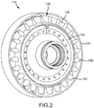
- FIG. 2 is a perspective of a turbine rotor section 110 of gas turbine engine 20 in FIG. 1 , as viewed forward to aft.
- the turbine rotor section 110 includes a blade outer air seal (BOAS) 120 surrounding a turbine rotor assembly 130.
- Turbine rotor assembly 130 may comprise a blade ring 132, a turbine disk 134, and a plurality of blades 100. Blades 100 may be coupled to turbine disk 134.
- BOAS 120 may be configured as a cylindrical shroud and may be disposed concentric to turbine rotor assembly 130.
- a radial gap (i.e., a blade running clearance) may be located between an outermost diameter of turbine rotor assembly 130 and BOAS 120 (i.e., between a tip end of blades 100 and a radially inward surface of BOAS 120).
- FIGs. 3A and 3B illustrate a perspective pressure side view and a plan view, respectively, of a turbine blade 100 having oblong openings, in accordance with various embodiments.
- Blade 100 comprises a pressure side wall 150 (also referred to as a pressure side), a suction side wall 152 (also referred to as a suction side) opposite the pressure side wall 150, and a tip wall 154 (also referred to as a blade tip) extending between the pressure side wall 150 and the suction side wall 152.
- pressure side wall 150 may be concave and suction side wall 152 may be convex.
- Blade 100 further comprises a leading edge 156 and a trailing edge 158 opposite the leading edge 156.
- Leading edge 156 may be oriented forward of trailing edge 158.
- a radially outward surface 155 of tip wall 154 may extend between leading edge 156 and trailing edge 158 and between pressure side 150 and suction side 152.
- Tip wall 154 and surface 155 may be oriented radially inward of BOAS 120, with momentary reference to FIG. 2 , and away from engine central longitudinal axis A-A', with momentary reference to FIG. 1 .
- Openings 200 may be formed in tip wall 154 using any suitable manner. Openings 200 may be formed during the manufacturing of blade 100.
- manufacturing blade 100 may comprise forming a ceramic core and then pouring a metal around the ceramic core. Rods may be placed in the mold when the ceramic core is formed, and the ceramic core may harden with the rods attached therein. The rods may hold the ceramic core in place while the metal, which will ultimately form the blade, is poured. The rods tend to prevent the ceramic core from moving during application of the metal. Preventing movement of the ceramic core tends to increase wall thickness precision and wall thickness accuracy when forming blades 100. Once the metal cools and/or hardens, the ceramic core and rods are removed by leaching, leaving the metal blade.
- a location of openings 200 corresponds to the location of the rods in the ceramic core
- a shape of openings 200 corresponds to the shape of the rods.
- FIG. 3C illustrates an opening 200.
- Opening 200 (and the rods that form openings 200) may be oblong. Stated another way, a first dimension D1 of opening 200 may be greater than a second dimension D2 of opening 200.
- a ratio of dimension D1 to dimension D2 may be between 1.5:1 and 15:1. In various embodiments, a ratio of dimension D1 to dimension D2 may be between 2:1 and 10:1.
- Opening 200 may comprise a first semi-circular end 202 and a second semi-circular end 204 opposite first semi-circular end 202.
- First semi-circular end 202 may have a radius R1.
- Second semi-circular end 204 may have a radius R2.
- radius R1 may be equal to radius R2.
- a first sidewall 206 and a second sidewall 208 may connect semi-circular ends 202 and 204.
- First sidewall 206 may be parallel to second sidewall 208.
- Sidewall 206 may include a length L1 that extends from first semi-circular end 202 to second semi-circular end 204.
- Sidewall 208 may include a length L2 that extends from first semi-circular end 202 to second semi-circular end 204.
- Length L1 of sidewall 206 may be equal to length L2 of sidewall 208.
- a ratio of length L1 to radius R1 may be between 1:1 and 28:1.
- a ratio of length L1 to radius R1 may be between 2:1 and 18:1.
- openings 200 may be positioned in tip wall 154 with the greater dimension D1 of opening 200 oriented in a direction extending from leading edge 156 toward trailing edge 158, and with the smaller dimension D2 of opening 200 oriented in a direction extending from pressure side 150 toward suction side 152.
- the oblong shape of openings 200 as compared to openings having a circular shape (i.e., openings having equal dimensions in the pressure side to suction side direction and in the leading edge to trailing edge direction), may provide increased blade cooling and increased engine efficiency.
- a cooling flow e.g., a cooling airstream
- the cooling gas may then be pushed aft due to the hot gas path flow.
- the cooling flow expelled from openings 200 may extend to the internal surface of BOAS 120, with momentary reference to FIG. 2 , and may block hot gasses flowing from pressure side 150 to suction side 152 over blade tip 154.
- the oblong shape of openings 200 tends to create a larger effective blockage, as compared to circular openings of the same surface area as measured along surface 155.
- the larger effective blockage tends to reduce an amount of hot gas flow, or leakage, over blade tip 154.
- openings 200 with a greater dimension D1 may be disposed in areas of tip wall 154 that are more susceptible to hot gas flow leakage or areas that may provide more efficient blocking of hot gas flow over blade tip 154.
- a ratio of dimension D1 to dimension D2 may be greater in openings 200 that are proximate to leading edge 156, as compared to openings 200 that are proximate to trailing edge 158.
- a ratio of dimension D1 to dimension D2 may be greater in openings 200 that are proximate to pressure side 150, as compared to openings 200 that are proximate to suction side 152.
- Hot gas flow that leaks over blade tip 154 tends to have an associated performance penalty because the leaked hot gas flow does not provide as much work to turbine blades 100 as hot gas flow that does not go over the blade tips.
- the oblong shape of openings 200 may increase an aerodynamic efficiency of gas turbine engine 20 ( FIG. 1 ) as the air flow from openings 200 decreases hot gas flow leakage over tip wall 154 and/or reduces a leakage of hot gas flow over blade tips 154.
- the cooling airflow expelled from oblong openings 200 may cover more area between the leading edge and trailing edge of blade 100, as compared to the airflow expelled from circular-shaped openings of the same surface area. The larger coverage area may block more hot gas flow and/or reduce an amount of hot gas flow leaking over blade tips 154.
- Oblong openings 200 may also provide improved cooling of blade 100.
- the cooling flow from openings 200 may create a cooling film over tip wall 154 (i.e., a cooling air flow covering portions of tip wall 154).
- the cooling film formed by oblong openings 200 tends to provide a greater coverage area and protect a greater surface area of tip wall 154 from the hot combustion gases, as compared to the cooling film formed by circular openings of the same surface area. Cooling and/or protecting a greater surface area of tip wall 154 from hot gasses may decrease thermal heat load of blades 100 and may increase a total life of blades 100.
- each opening 200 may be about an equal distance away from suction side 152. As used here "about an equal distance” means ⁇ 1.0 millimeter (mm).
- a first opening 200a may be a greater distance from suction side 152 than a second opening 200b.
- openings 200 may be formed with equal surface area.
- a cross-sectional area of first opening 200a at surface 155 of tip wall 154 i.e., the area of a cross-section of first opening 200a in the XZ plane at surface 155) may be equal to the cross-sectional area of the other openings 200 at surface 155.
- openings 200 may comprise a constant a cross-sectional area through the tip wall 154.
- Openings 200 may also vary in surface area. In various embodiments, openings 200 with greater surface area may be formed in, or proximate to, thicker portions of tip wall 154. With reference to FIGs. 5A and 5B , tip wall 154 may vary in thickness due to, for example, variance in the radial length of an internal chamber 215 within blade 100. In various embodiments, a first portion 154a of tip wall 154 may have a thickness 217 extending from internal chamber 215 to surface 155, and a second portion 154b of tip wall 154 may have a thickness 219 extending from internal chamber 215 to surface 155 that is less than thickness 217.
- First opening 200a may be formed in first portion 154a and may have a greater area than a second opening 200b formed in second portion 154b. Disposing openings with greater area in, or close to, thicker portions of tip wall 154 may increase cooling of blade 100.
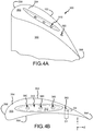
- FIGs. 4A and 4B illustrate a perspective pressure side view and a perspective radially inward view, respectively, of a blade 300 having a squealer pocket and oblong openings, in accordance with various embodiments.
- Blade 300 comprises a pressure side wall 350 (also referred to as a pressure side), a suction side wall 352 (also referred to as a suction side) opposite the pressure side wall 350, and a tip wall 354 (also referred to as a blade tip) extending between and coupling the pressure side wall 350 and the suction side wall 352.
- pressure side wall 350 may be concave and suction side wall 352 may be convex.
- Blade 300 further comprises a leading edge 356 and a trailing edge 358 opposite the leading edge 356.
- Leading edge 356 may be oriented forward trailing edge 358.
- Blade tip 354 may be oriented radially outward. Stated another way, with momentary reference to FIG. 2 , blade 300 may be included in turbine rotor assembly 130 and blade tip 354 may radially inward relative to BOAS 120. Stated yet another way, blade tip 354 may be oriented away from engine central longitudinal axis A-A', with momentary reference to FIG. 1 .
- tip wall 354 may comprise a squealer or semi-squealer tip having a tip pocket 310 (also referred to as a squealer tip pocket).
- Tip pocket 310 may comprise a recessed area formed in tip wall 354.
- a surface 312 of tip pocket 310 may be recessed with respect to a radially outward surface 355 of tip wall 354.
- a thermal barrier coating may be disposed in tip pocket 310.
- a plurality of oblong openings 360 may be formed in tip wall 354 and in tip pocket 310. Openings 360 may be formed and/or positioned in tip wall 354 and tip pocket 310 with the greater dimension D1 of openings 360 oriented in a direction extending from leading edge 356 toward trailing edge 358 and the smaller dimension D2 of opening 360 oriented in direction extending from pressure side 350 toward suction side 352.
- the position of openings 360, number of openings 360, size of openings 360, and distribution of openings 360 in tip wall 354 and in tip pocket 310 may be selected to provide predetermined amounts of cooling and/or gas flow blocking to various portions of blade 300. For example, if blade 300 may benefit from more cooling, then a greater number openings 360 and/or openings 360 with greater surface area may be located in tip pocket 310. If blade 300 and/or gas turbine engine 20 ( FIG. 1 ) may benefit from blocking a greater amount hot gas flow (i.e., reducing hot gas leakage over tip wall 354), then a great number of openings 360 and/or openings 360 with greater surface area may be located in tip wall 354 (i.e., outside tip pocket 310).
- openings 360 with a greater dimension D1 may be disposed in areas of tip wall and/or tip pocket 310 that are more susceptible to hot gas flow leakage and/or in areas that may provide more efficient blocking of hot gas flow over blade tip 354.
- a ratio of dimension D1 to dimension D2 may be greater in openings 360 that are proximate to leading edge 356, as compared to a ratio of dimension D1 to dimension D2 in openings 360 that are proximate to trailing edge 358.
- a ratio of dimension D1 to dimension D2 may be greater in openings 360 that are proximate to pressure side 350, as compared to a ratio of dimension D1 to dimension D2 in openings 360 that are proximate to suction side 352.
- Hot gas flow that leaks over blade tip 354 tends to have an associated performance penalty because the leaked hot gas flow does not provide as much work to turbine blades 300 as hot gas flow that does not go over the blade tips.
- the oblong shape of openings 360 may increase an aerodynamic efficiency of gas turbine engine 20 ( FIG. 1 ) as the air flow from openings 200 covers a greater leading edge to trailing edge distance and may block more hot gas flow and/or reduce an amount of hot gas flow leaking over blade tips 354.
- openings 360 with a greater dimension D1 may be disposed in areas of tip wall 354 and/or tip pocket 310 that would benefit from increased cooling.
- a ratio of dimension D1 to dimension D2 may be greater in openings 360 that are proximate to thicker portions of tip wall 354, as compared to openings 360 that are proximate to thinner portions of tip wall 354.
- the cooling film formed from oblong openings 360 tends to provide a greater coverage area and/or protect a greater surface area of tip wall 354 from the hot combustion gases, as compared to the cooling film formed by circular-shaped openings of the same surface area. Cooling and/or protecting a greater surface area of tip wall 354 from hot gasses tends to decrease thermal load of blades 300 and may increase a total life of blades 300.
- FIGs. 6A, 6B, 6C, 6D, and 6E illustrate oblong openings, in accordance with various embodiments.
- FIG. 6A shows an oblong opening 400 comprising an oval shape (i.e., an oval-shaped cross-section).
- a dimension D4 of openings 400 may be greater than a dimension D5 of openings 400.
- One or more openings 400 may be formed in a tip wall similar to openings 200 of FIG. 3A , and/or in a tip pocket, similar to openings 360 of FIG. 4A . Openings 400 may be positioned with the greater dimension D4 oriented from the leading edge of the blade toward the trailing edge of the blade.
- FIG. 6B shows an oblong opening 402 having a figure-eight shape (i.e., a figure-eight-shaped cross-section).
- a dimension D6 of openings 402 may be greater than a dimension D7 of openings 402.
- One or more openings 402 may be formed in a tip wall, similar to openings 200 of FIG. 3A , and/or in a tip pocket, similar to openings 360 of FIG. 4A . Openings 402 may be positioned with the greater dimension D6 oriented from the leading edge of the blade toward the trailing edge of the blade.
- FIG. 6C shows an oblong opening 404 having a hexagonal shape (i.e., a hexagon-shaped cross-section).
- a dimension D8 of openings 404 may be greater than a dimension D9 of openings 404.
- a fillet 406 may be formed in one or more of the corners of openings 404.
- One or more openings 404 may be formed in a tip wall, similar to openings 200 of FIG. 3A , and/or in a tip pocket, similar to openings 360 of FIG. 4A . Openings 404 may be positioned with the greater dimension D8 oriented from the leading edge of the blade toward the trailing edge of the blade.
- FIG. 6D shows an oblong opening 408 having an decagonal shape (i.e., an decagon-shaped cross-section).
- a dimension D10 of openings 408 may be greater than a dimension D11 of openings 408.
- a filet 410 may be formed in one or more of the corners of openings 408.
- One or more openings 408 may be formed in a tip wall, similar to openings 200 of FIG. 3A , and/or in a tip pocket, similar to openings 360 of FIG. 4A . Openings 408 may be positioned with the greater dimension D10 oriented from the leading edge of the blade toward the trailing edge of the blade.
- FIG. 6E shows an oblong opening 412 having a diamond shape (i.e., a diamond-shaped cross-section).
- a dimension D12 of openings 412 may be greater than a dimension D13 of openings 412.
- a fillet 414 may be formed in one or more of the corners of openings 412.
- One or more openings 412 may be formed in a tip wall, similar to openings 200 of FIG. 3A , and/or in a tip pocket, similar to openings 360 of FIG. 4A .
- Openings 412 may be positioned with the greater dimension D12 oriented from the leading edge of the blade toward the trailing edge of the blade.
- the openings illustrated in FIG. 3C , and FIGs. 6A-6E are provided as examples of oblong openings, it should be understood that any shape opening comprising a first dimension greater than a second dimension may be formed in a tip wall and/or tip pocket.
- FIG. 7 illustrates a method 500 of making a turbine blade, in accordance with various embodiments.
- Method 500 may comprise forming a tip wall extending from a pressure side of the turbine blade to a suction side of the turbine blade (step 502), and forming a first opening in the tip wall (step 504).
- the first opening may comprise a first dimension and a second dimension less than the first dimension. The first dimension may be oriented in a direction extending from a leading edge of the turbine blade to a trailing edge of the turbine blade.
- step 502 may include forming tip wall 154 extending from pressure side 150 to suction side 152 of blade 100.
- Step 504 may comprise forming a first opening 200a in tip wall 154.
- First opening 200a may comprise first dimension D1 and second dimension D2.
- Dimension D1 may be oriented in a direction extending from leading edge 156 to trailing edge 158.
- method 500 may further comprise forming a tip pocket in the tip wall (step 506), and forming a second opening in the tip pocket (step 508).
- step 506 may include forming tip pocket 310 in tip wall 354.
- Step 508 may including forming opening 360 in tip pocket 310.
- references to "one embodiment”, “an embodiment”, “various embodiments”, etc. indicate that the embodiment described may include a particular feature, structure, or characteristic, but every embodiment may not necessarily include the particular feature, structure, or characteristic. Moreover, such phrases are not necessarily referring to the same embodiment. Further, when a particular feature, structure, or characteristic is described in connection with an embodiment, it is submitted that it is within the knowledge of one skilled in the art to affect such feature, structure, or characteristic in connection with other embodiments whether or not explicitly described. After reading the description, it will be apparent to one skilled in the relevant art(s) how to implement the disclosure in alternative embodiments.
Abstract
Description
- The present disclosure relates generally to components of gas turbine engines and, more specifically, to turbine blades including tip walls with oblong openings.
- A gas turbine engine typically includes a fan section, a compressor section, a combustor section, and a turbine section. Air entering the compressor section is compressed and delivered into the combustion section where it is mixed with fuel and ignited to generate a high-speed exhaust gas flow. The high-speed exhaust gas flow expands through the turbine section to drive the compressor and the fan section.
- The compressor section and/or the turbine section may include rotatable blades and stationary vanes. A blade outer air seal (BOAS) may be mounted within the engine casing, and positioned in close proximity to the outermost tips of the rotatable blades. Space between the BOAS and the blade tips may be maintained to avoid the blade tips rubbing against the BOAS due to the expansion of the blade relative to the BOAS. However, the efficiency of the gas turbine engine may be undesirably affected by having a large tip clearance between the blade tips and the BOAS, as the hot gas flow may leak through the space between the blade tip and the BOAS.
- A turbine blade may comprise a pressure side wall and a suction side wall opposite the pressure side wall. A tip wall may extend between the pressure side wall and the suction side wall and may comprise a first opening having an oblong shape. A first dimension of the first opening may be greater than a second dimension of the first opening. The first dimension may be oriented in a direction extending from a leading edge of the turbine blade toward a trailing edge of the turbine blade.
- In various embodiments, the first opening may comprise a first semi-circular end having a first radius, a second semi-circular end opposite the first semi-circular end, a first sidewall extending from the first semi-circular end to the second semi-circular end, and a second sidewall parallel to the first sidewall and extending from the first semi-circular end to the second semi-circular end. A ratio of a length of the first sidewall to the first radius may be between 1:1 and 28:1.
- In various embodiments, the tip wall may further comprise a second opening. A first surface area of the first opening may be equal to a second surface area of the second opening. A first surface area of the first opening may be greater than a second surface area of the second opening. The first opening may be disposed closer to the leading edge of the turbine blade than the second opening. The first opening may be disposed closer to the pressure side wall of the turbine blade than the second opening. A tip pocket may be formed in the tip wall. The first opening may be located in the tip pocket and the second opening may be located outside the tip pocket.
- A gas turbine engine may comprise a turbine including a turbine rotor assembly. The turbine rotor assembly may comprise a turbine disk and a blade coupled to the turbine disk. The blade may include a first opening formed in a tip wall of the blade. The first opening may comprise a first dimension and a second dimension less than the first dimension. The first dimension may be oriented in a direction extending from a leading edge of the blade toward a trailing edge of the blade. A BOAS may be disposed around the turbine rotor assembly.
- In various embodiments, the first opening may direct an airflow from the blade toward the BOAS. A ratio of the first dimension to the second dimension may be between 1.5:1 and 15:1. A tip pocket may be formed in the tip wall of the blade. A second opening may be located in the tip pocket. A first surface area of the second opening may be greater than a second surface area of the first opening. A first surface area of the second opening may be less than a second surface area of the first opening. A first surface area of the second opening may be equal to a second surface area of the first opening.
- A method of making a turbine blade may comprise forming a tip wall extending between a pressure side of the turbine blade and a suction side of the turbine blade, and forming a first opening in the tip wall. The first opening may comprise an oblong shape. A first dimension of the first opening may be oriented in a direction extending from a leading edge of the turbine blade toward a trailing edge of the turbine blade.
- In various embodiments, the method may further comprise forming a tip pocket in the tip wall. The method may further comprise forming a second opening in the tip pocket.
- The foregoing features and elements may be combined in various combinations without exclusivity, unless expressly indicated otherwise. These features and elements as well as the operation thereof will become more apparent in light of the following description and the accompanying drawings. It should be understood, however, the following description and drawings are intended to be exemplary in nature and non-limiting.
- The subject matter of the present disclosure is particularly pointed out and distinctly claimed in the concluding portion of the specification. A more complete understanding of the present disclosure, however, may best be obtained by referring to the detailed description and claims when considered in connection with the figures, wherein like numerals denote like elements.
-
FIG. 1 illustrates a cross-section view of an exemplary gas turbine engine, in accordance with various embodiments; -
FIG. 2 illustrates a perspective view of an exemplary turbine rotor assembly of a gas turbine engine, in accordance with various embodiments; and -
FIGs. 3A and 3B illustrate a perspective view and a plan view, respectively, of a turbine blade with oblong openings, in accordance with various embodiments; -
FIG. 3C illustrates an oblong opening for a turbine blade tip, in accordance with various embodiments; -
FIGs. 4A and 4B illustrate perspective views of a turbine blade having a squealer pocket with oblong tip openings, in accordance with various embodiments; -
FIGs. 5A and 5B illustrate cross-sections of the turbine blade ofFIG. 3A taken alongline 5A-5A andline 5B-5B, respectively, inFIG. 3A , in accordance with various embodiments; -
FIGs. 6A, 6B, 6C, 6D, and 6E illustrate oblong openings, in accordance with various embodiments; and -
FIGs. 7 and 8 illustrate a method of making a turbine blade having oblong openings, in accordance with various embodiments. - The detailed description of exemplary embodiments herein makes reference to the accompanying drawings, which show exemplary embodiments by way of illustration. While these exemplary embodiments are described in sufficient detail to enable those skilled in the art to practice the exemplary embodiments of the disclosure, it should be understood that other embodiments may be realized and that logical changes and adaptations in design and construction may be made in accordance with this disclosure and the teachings herein. Thus, the detailed description herein is presented for purposes of illustration only and not limitation. The steps recited in any of the method or process descriptions may be executed in any order and are not necessarily limited to the order presented.
- Furthermore, any reference to singular includes plural embodiments, and any reference to more than one component or step may include a singular embodiment or step. Also, any reference to attached, fixed, connected or the like may include permanent, removable, temporary, partial, full and/or any other possible attachment option. Additionally, any reference to without contact (or similar phrases) may also include reduced contact or minimal contact. Surface cross hatching lines may be used throughout the figures to denote different parts but not necessarily to denote the same or different materials. Throughout the present disclosure, like reference numbers denote like elements. Accordingly, elements with like element numbering may be shown in the figures, but may not be necessarily be repeated herein for the sake of clarity.
- As used herein, "aft" refers to the direction associated with the tail (i.e., the back end) of an aircraft, or generally, to the direction of exhaust of the gas turbine engine. As used herein, "forward" refers to the direction associated with the nose (i.e., the front end) of an aircraft, or generally, to the direction associated with the intake of a gas turbine engine. As used herein, "distal" refers to the direction outward, or generally, away from a reference component. As used herein, "proximal" and/or "proximate" refers to a direction inward, or generally, towards the reference component.
- A first component that is "radially outward" of a second component means that the first component is positioned at a greater distance away from the engine central longitudinal axis than the second component. A first component that is "radially inward" of a second component means that the first component is positioned closer to the engine central longitudinal axis than the second component. In the case of components that rotate circumferentially about the engine central longitudinal axis, a first component that is radially inward of a second component rotates through a circumferentially shorter path than the second component. The terminology "radially outward" and "radially inward" may also be used relative to references other than the engine central longitudinal axis.
- With reference to
FIG. 1 , agas turbine engine 20 is shown according to various embodiments.Gas turbine engine 20 may be a two-spool turbofan that generally incorporates afan section 22, acompressor section 24, acombustor section 26, and aturbine section 28. Alternative engines may include, for example, an augmentor section among other systems or features. In operation,fan section 22 can drive coolant (e.g., air) along a path of bypass airflow B whilecompressor section 24 can drive coolant along a core flowpath C for compression and communication intocombustor section 26 then expansion throughturbine section 28. Although depicted as a turbofangas turbine engine 20 herein, it should be understood that the concepts described herein are not limited to use with turbofans as the teachings may be applied to other types of turbine engines including three-spool architectures. -
Gas turbine engine 20 may generally comprise alow speed spool 30 and ahigh speed spool 32 mounted for rotation about an engine central longitudinal axis A-A' relative to an engine static structure 36 (also referred to as an engine casing structure) viaseveral bearing systems 38, 38-1, and 38-2. Engine central longitudinal axis A-A' is oriented in the z direction on the provided xyz axes. It should be understood that various bearingsystems 38 at various locations may alternatively or additionally be provided, including for example, bearingsystem 38, bearing system 38-1, and bearing system 38-2. -
Low speed spool 30 may generally comprise aninner shaft 40 that interconnects afan 42, alow pressure compressor 44, and alow pressure turbine 46.Inner shaft 40 may be connected to fan 42 through a gearedarchitecture 48 that can drivefan 42 at a lower speed thanlow speed spool 30.Geared architecture 48 may comprise agear assembly 60 enclosed within agear housing 62.Gear assembly 60 couplesinner shaft 40 to a rotating fan structure.High speed spool 32 may comprise anouter shaft 50 that interconnects ahigh pressure compressor 52 andhigh pressure turbine 54. As used herein, a "high pressure" compressor or turbine experiences a higher pressure than a corresponding "low pressure" compressor or turbine. - A
combustor 56 may be located betweenhigh pressure compressor 52 andhigh pressure turbine 54. Amid-turbine frame 57 ofengine casing structure 36 may be located generally betweenhigh pressure turbine 54 andlow pressure turbine 46.Mid-turbine frame 57 may support one ormore bearing systems 38 inturbine section 28.Inner shaft 40 andouter shaft 50 may be concentric and rotate via bearingsystems 38 about the engine central longitudinal axis A-A', which is collinear with their longitudinal axes. - The core airflow C may be compressed by
low pressure compressor 44 thenhigh pressure compressor 52, mixed and burned with fuel incombustor 56, then expanded overhigh pressure turbine 54 andlow pressure turbine 46.Turbines low speed spool 30 andhigh speed spool 32 in response to the expansion. -
Gas turbine engine 20 may be, for example, a high-bypass ratio geared aircraft engine. In various embodiments, the bypass ratio ofgas turbine engine 20 may be greater than about six (6). In various embodiments, the bypass ratio ofgas turbine engine 20 may be greater than ten (10). In various embodiments, gearedarchitecture 48 may be an epicyclic gear train, such as a star gear system (sun gear in meshing engagement with a plurality of star gears supported by a carrier and in meshing engagement with a ring gear) or other gear system.Geared architecture 48 may have a gear reduction ratio of greater than about 2.3 andlow pressure turbine 46 may have a pressure ratio that is greater than about five (5). In various embodiments, the bypass ratio ofgas turbine engine 20 is greater than about ten (10:1). In various embodiments, the diameter offan 42 may be significantly larger than that of thelow pressure compressor 44, and thelow pressure turbine 46 may have a pressure ratio that is greater than about five (5:1).Low pressure turbine 46 pressure ratio may be measured prior to inlet oflow pressure turbine 46 as related to the pressure at the outlet oflow pressure turbine 46 prior to an exhaust nozzle. It should be understood, however, that the above parameters are exemplary of various embodiments of a suitable geared architecture engine and that the present disclosure contemplates other gas turbine engines including direct drive turbofans. A gas turbine engine may comprise an industrial gas turbine (IGT) or a geared aircraft engine, such as a geared turbofan, or non-geared aircraft engine, such as a turbofan, or may comprise any gas turbine engine as desired. - Each of the
compressor section 24 and theturbine section 28 may include alternating rows of rotor assemblies and vane assemblies (shown schematically) that carry airfoils that extend into the core flow path C. For example, the rotor assemblies in theturbine section 28 may carry a plurality ofrotating blades 100, and each vane assembly may carry a plurality ofstationary vanes 27 that extend into the core flow path C. Theblades 100 of the rotor assemblies in the turbine section create or extract energy (in the form of pressure) from the core airflow that is communicated through thegas turbine engine 20 along the core flow path C. Thevanes 27 of the vane assemblies direct the core airflow to theblades 100 to either add or extract energy. - Various components of a
gas turbine engine 20, including but not limited to theblades 100 and thevanes 27 of thecompressor section 24 and theturbine section 28, may be subjected to repetitive thermal cycling under widely ranging temperatures and pressures. The hardware of theturbine section 28 is particularly subjected to relatively extreme operating conditions. Therefore, some components may require internal cooling circuits for cooling the parts during engine operation. - Turbine blades of the present disclosure may include oblong openings formed in the tip of the turbine blade. The oblong openings may be positioned with a longer dimension of the openings extending generally from a leading edge toward a trailing edge. The oblong shape of the openings may cool and protect a greater area of the blade, as compared to circular-shaped openings of the same surface area. The oblong shape of the openings may also decrease gas leakage over the blade tip, which may lead to increased engine efficiency.
-
FIG. 2 is a perspective of aturbine rotor section 110 ofgas turbine engine 20 inFIG. 1 , as viewed forward to aft. Theturbine rotor section 110 includes a blade outer air seal (BOAS) 120 surrounding aturbine rotor assembly 130.Turbine rotor assembly 130 may comprise ablade ring 132, aturbine disk 134, and a plurality ofblades 100.Blades 100 may be coupled toturbine disk 134.BOAS 120 may be configured as a cylindrical shroud and may be disposed concentric toturbine rotor assembly 130. A radial gap (i.e., a blade running clearance) may be located between an outermost diameter ofturbine rotor assembly 130 and BOAS 120 (i.e., between a tip end ofblades 100 and a radially inward surface of BOAS 120). -
FIGs. 3A and 3B illustrate a perspective pressure side view and a plan view, respectively, of aturbine blade 100 having oblong openings, in accordance with various embodiments.Blade 100 comprises a pressure side wall 150 (also referred to as a pressure side), a suction side wall 152 (also referred to as a suction side) opposite thepressure side wall 150, and a tip wall 154 (also referred to as a blade tip) extending between thepressure side wall 150 and thesuction side wall 152. In various embodiments,pressure side wall 150 may be concave andsuction side wall 152 may be convex.Blade 100 further comprises aleading edge 156 and a trailingedge 158 opposite theleading edge 156. Leadingedge 156 may be oriented forward of trailingedge 158. A radiallyoutward surface 155 oftip wall 154 may extend betweenleading edge 156 and trailingedge 158 and betweenpressure side 150 andsuction side 152.Tip wall 154 andsurface 155 may be oriented radially inward ofBOAS 120, with momentary reference toFIG. 2 , and away from engine central longitudinal axis A-A', with momentary reference toFIG. 1 . - One or
more openings 200 may be formed intip wall 154 using any suitable manner.Openings 200 may be formed during the manufacturing ofblade 100. For example, in various embodiments,manufacturing blade 100 may comprise forming a ceramic core and then pouring a metal around the ceramic core. Rods may be placed in the mold when the ceramic core is formed, and the ceramic core may harden with the rods attached therein. The rods may hold the ceramic core in place while the metal, which will ultimately form the blade, is poured. The rods tend to prevent the ceramic core from moving during application of the metal. Preventing movement of the ceramic core tends to increase wall thickness precision and wall thickness accuracy when formingblades 100. Once the metal cools and/or hardens, the ceramic core and rods are removed by leaching, leaving the metal blade. In various embodiments, a location ofopenings 200 corresponds to the location of the rods in the ceramic core, and a shape ofopenings 200 corresponds to the shape of the rods. - In accordance with various embodiments,
FIG. 3C illustrates anopening 200. Opening 200 (and the rods that form openings 200) may be oblong. Stated another way, a first dimension D1 of opening 200 may be greater than a second dimension D2 ofopening 200. In various embodiments, a ratio of dimension D1 to dimension D2 may be between 1.5:1 and 15:1. In various embodiments, a ratio of dimension D1 to dimension D2 may be between 2:1 and 10:1. - Opening 200 may comprise a first
semi-circular end 202 and a secondsemi-circular end 204 opposite firstsemi-circular end 202. Firstsemi-circular end 202 may have a radius R1. Secondsemi-circular end 204 may have a radius R2. In various embodiments, radius R1 may be equal to radius R2. Afirst sidewall 206 and asecond sidewall 208 may connectsemi-circular ends First sidewall 206 may be parallel tosecond sidewall 208.Sidewall 206 may include a length L1 that extends from firstsemi-circular end 202 to secondsemi-circular end 204.Sidewall 208 may include a length L2 that extends from firstsemi-circular end 202 to secondsemi-circular end 204. Length L1 ofsidewall 206 may be equal to length L2 ofsidewall 208. In various embodiments, a ratio of length L1 to radius R1 may be between 1:1 and 28:1. In various embodiments, a ratio of length L1 to radius R1 may be between 2:1 and 18:1. - With reference to
FIG. 3B ,openings 200 may be positioned intip wall 154 with the greater dimension D1 of opening 200 oriented in a direction extending from leadingedge 156 toward trailingedge 158, and with the smaller dimension D2 of opening 200 oriented in a direction extending frompressure side 150 towardsuction side 152. The oblong shape ofopenings 200, as compared to openings having a circular shape (i.e., openings having equal dimensions in the pressure side to suction side direction and in the leading edge to trailing edge direction), may provide increased blade cooling and increased engine efficiency. For example, during operation, a cooling flow (e.g., a cooling airstream) may exit opening 200 normal to the surface oftip wall 154. The cooling gas may then be pushed aft due to the hot gas path flow. The cooling flow expelled fromopenings 200 may extend to the internal surface ofBOAS 120, with momentary reference toFIG. 2 , and may block hot gasses flowing frompressure side 150 tosuction side 152 overblade tip 154. The oblong shape ofopenings 200 tends to create a larger effective blockage, as compared to circular openings of the same surface area as measured alongsurface 155. The larger effective blockage tends to reduce an amount of hot gas flow, or leakage, overblade tip 154. - In various embodiments,
openings 200 with a greater dimension D1 may be disposed in areas oftip wall 154 that are more susceptible to hot gas flow leakage or areas that may provide more efficient blocking of hot gas flow overblade tip 154. For example, a ratio of dimension D1 to dimension D2 may be greater inopenings 200 that are proximate to leadingedge 156, as compared toopenings 200 that are proximate to trailingedge 158. In various embodiments, a ratio of dimension D1 to dimension D2 may be greater inopenings 200 that are proximate topressure side 150, as compared toopenings 200 that are proximate tosuction side 152. - Hot gas flow that leaks over
blade tip 154 tends to have an associated performance penalty because the leaked hot gas flow does not provide as much work toturbine blades 100 as hot gas flow that does not go over the blade tips. In this manner, the oblong shape ofopenings 200 may increase an aerodynamic efficiency of gas turbine engine 20 (FIG. 1 ) as the air flow fromopenings 200 decreases hot gas flow leakage overtip wall 154 and/or reduces a leakage of hot gas flow overblade tips 154. Stated another way, the cooling airflow expelled fromoblong openings 200 may cover more area between the leading edge and trailing edge ofblade 100, as compared to the airflow expelled from circular-shaped openings of the same surface area. The larger coverage area may block more hot gas flow and/or reduce an amount of hot gas flow leaking overblade tips 154. -
Oblong openings 200 may also provide improved cooling ofblade 100. The cooling flow fromopenings 200 may create a cooling film over tip wall 154 (i.e., a cooling air flow covering portions of tip wall 154). The cooling film formed byoblong openings 200 tends to provide a greater coverage area and protect a greater surface area oftip wall 154 from the hot combustion gases, as compared to the cooling film formed by circular openings of the same surface area. Cooling and/or protecting a greater surface area oftip wall 154 from hot gasses may decrease thermal heat load ofblades 100 and may increase a total life ofblades 100. - In various embodiments, each opening 200 may be about an equal distance away from
suction side 152. As used here "about an equal distance" means ± 1.0 millimeter (mm). In various embodiments, afirst opening 200a may be a greater distance fromsuction side 152 than asecond opening 200b. In various embodiments,openings 200 may be formed with equal surface area. In other words, a cross-sectional area offirst opening 200a atsurface 155 of tip wall 154 (i.e., the area of a cross-section offirst opening 200a in the XZ plane at surface 155) may be equal to the cross-sectional area of theother openings 200 atsurface 155. In various embodiments,openings 200 may comprise a constant a cross-sectional area through thetip wall 154. -
Openings 200 may also vary in surface area. In various embodiments,openings 200 with greater surface area may be formed in, or proximate to, thicker portions oftip wall 154. With reference toFIGs. 5A and 5B ,tip wall 154 may vary in thickness due to, for example, variance in the radial length of aninternal chamber 215 withinblade 100. In various embodiments, afirst portion 154a oftip wall 154 may have athickness 217 extending frominternal chamber 215 to surface 155, and asecond portion 154b oftip wall 154 may have athickness 219 extending frominternal chamber 215 to surface 155 that is less thanthickness 217.First opening 200a may be formed infirst portion 154a and may have a greater area than asecond opening 200b formed insecond portion 154b. Disposing openings with greater area in, or close to, thicker portions oftip wall 154 may increase cooling ofblade 100. -
FIGs. 4A and 4B illustrate a perspective pressure side view and a perspective radially inward view, respectively, of ablade 300 having a squealer pocket and oblong openings, in accordance with various embodiments.Blade 300 comprises a pressure side wall 350 (also referred to as a pressure side), a suction side wall 352 (also referred to as a suction side) opposite thepressure side wall 350, and a tip wall 354 (also referred to as a blade tip) extending between and coupling thepressure side wall 350 and thesuction side wall 352. In various embodiments,pressure side wall 350 may be concave andsuction side wall 352 may be convex.Blade 300 further comprises aleading edge 356 and a trailingedge 358 opposite theleading edge 356. Leadingedge 356 may be oriented forward trailingedge 358.Blade tip 354 may be oriented radially outward. Stated another way, with momentary reference toFIG. 2 ,blade 300 may be included inturbine rotor assembly 130 andblade tip 354 may radially inward relative toBOAS 120. Stated yet another way,blade tip 354 may be oriented away from engine central longitudinal axis A-A', with momentary reference toFIG. 1 . - In various embodiments,
tip wall 354 may comprise a squealer or semi-squealer tip having a tip pocket 310 (also referred to as a squealer tip pocket).Tip pocket 310 may comprise a recessed area formed intip wall 354. Asurface 312 oftip pocket 310 may be recessed with respect to a radiallyoutward surface 355 oftip wall 354. In various embodiments, a thermal barrier coating may be disposed intip pocket 310. - A plurality of
oblong openings 360, similar toopenings 200 inFIG. 3C , may be formed intip wall 354 and intip pocket 310.Openings 360 may be formed and/or positioned intip wall 354 andtip pocket 310 with the greater dimension D1 ofopenings 360 oriented in a direction extending from leadingedge 356 toward trailingedge 358 and the smaller dimension D2 of opening 360 oriented in direction extending frompressure side 350 towardsuction side 352. - In various embodiments, the position of
openings 360, number ofopenings 360, size ofopenings 360, and distribution ofopenings 360 intip wall 354 and intip pocket 310 may be selected to provide predetermined amounts of cooling and/or gas flow blocking to various portions ofblade 300. For example, ifblade 300 may benefit from more cooling, then agreater number openings 360 and/oropenings 360 with greater surface area may be located intip pocket 310. Ifblade 300 and/or gas turbine engine 20 (FIG. 1 ) may benefit from blocking a greater amount hot gas flow (i.e., reducing hot gas leakage over tip wall 354), then a great number ofopenings 360 and/oropenings 360 with greater surface area may be located in tip wall 354 (i.e., outside tip pocket 310). - In various embodiments,
openings 360 with a greater dimension D1 may be disposed in areas of tip wall and/ortip pocket 310 that are more susceptible to hot gas flow leakage and/or in areas that may provide more efficient blocking of hot gas flow overblade tip 354. For example, a ratio of dimension D1 to dimension D2 may be greater inopenings 360 that are proximate to leadingedge 356, as compared to a ratio of dimension D1 to dimension D2 inopenings 360 that are proximate to trailingedge 358. In various embodiments, a ratio of dimension D1 to dimension D2 may be greater inopenings 360 that are proximate topressure side 350, as compared to a ratio of dimension D1 to dimension D2 inopenings 360 that are proximate tosuction side 352. Hot gas flow that leaks overblade tip 354 tends to have an associated performance penalty because the leaked hot gas flow does not provide as much work toturbine blades 300 as hot gas flow that does not go over the blade tips. In this manner, the oblong shape ofopenings 360 may increase an aerodynamic efficiency of gas turbine engine 20 (FIG. 1 ) as the air flow fromopenings 200 covers a greater leading edge to trailing edge distance and may block more hot gas flow and/or reduce an amount of hot gas flow leaking overblade tips 354. - In various embodiments,
openings 360 with a greater dimension D1 may be disposed in areas oftip wall 354 and/ortip pocket 310 that would benefit from increased cooling. For example, a ratio of dimension D1 to dimension D2 may be greater inopenings 360 that are proximate to thicker portions oftip wall 354, as compared toopenings 360 that are proximate to thinner portions oftip wall 354. - The cooling film formed from
oblong openings 360 tends to provide a greater coverage area and/or protect a greater surface area oftip wall 354 from the hot combustion gases, as compared to the cooling film formed by circular-shaped openings of the same surface area. Cooling and/or protecting a greater surface area oftip wall 354 from hot gasses tends to decrease thermal load ofblades 300 and may increase a total life ofblades 300. -
FIGs. 6A, 6B, 6C, 6D, and 6E illustrate oblong openings, in accordance with various embodiments.FIG. 6A shows anoblong opening 400 comprising an oval shape (i.e., an oval-shaped cross-section). A dimension D4 ofopenings 400 may be greater than a dimension D5 ofopenings 400. One ormore openings 400 may be formed in a tip wall similar toopenings 200 ofFIG. 3A , and/or in a tip pocket, similar toopenings 360 ofFIG. 4A .Openings 400 may be positioned with the greater dimension D4 oriented from the leading edge of the blade toward the trailing edge of the blade. -
FIG. 6B shows anoblong opening 402 having a figure-eight shape (i.e., a figure-eight-shaped cross-section). A dimension D6 ofopenings 402 may be greater than a dimension D7 ofopenings 402. One ormore openings 402 may be formed in a tip wall, similar toopenings 200 ofFIG. 3A , and/or in a tip pocket, similar toopenings 360 ofFIG. 4A .Openings 402 may be positioned with the greater dimension D6 oriented from the leading edge of the blade toward the trailing edge of the blade. -
FIG. 6C shows anoblong opening 404 having a hexagonal shape (i.e., a hexagon-shaped cross-section). A dimension D8 ofopenings 404 may be greater than a dimension D9 ofopenings 404. In various embodiments, afillet 406 may be formed in one or more of the corners ofopenings 404. One ormore openings 404 may be formed in a tip wall, similar toopenings 200 ofFIG. 3A , and/or in a tip pocket, similar toopenings 360 ofFIG. 4A .Openings 404 may be positioned with the greater dimension D8 oriented from the leading edge of the blade toward the trailing edge of the blade. -
FIG. 6D shows anoblong opening 408 having an decagonal shape (i.e., an decagon-shaped cross-section). A dimension D10 ofopenings 408 may be greater than a dimension D11 ofopenings 408. In various embodiments, afilet 410 may be formed in one or more of the corners ofopenings 408. One ormore openings 408 may be formed in a tip wall, similar toopenings 200 ofFIG. 3A , and/or in a tip pocket, similar toopenings 360 ofFIG. 4A .Openings 408 may be positioned with the greater dimension D10 oriented from the leading edge of the blade toward the trailing edge of the blade. -
FIG. 6E shows anoblong opening 412 having a diamond shape (i.e., a diamond-shaped cross-section). A dimension D12 ofopenings 412 may be greater than a dimension D13 ofopenings 412. In various embodiments, afillet 414 may be formed in one or more of the corners ofopenings 412. One ormore openings 412 may be formed in a tip wall, similar toopenings 200 ofFIG. 3A , and/or in a tip pocket, similar toopenings 360 ofFIG. 4A .Openings 412 may be positioned with the greater dimension D12 oriented from the leading edge of the blade toward the trailing edge of the blade. The openings illustrated inFIG. 3C , andFIGs. 6A-6E are provided as examples of oblong openings, it should be understood that any shape opening comprising a first dimension greater than a second dimension may be formed in a tip wall and/or tip pocket. -
FIG. 7 illustrates amethod 500 of making a turbine blade, in accordance with various embodiments.Method 500 may comprise forming a tip wall extending from a pressure side of the turbine blade to a suction side of the turbine blade (step 502), and forming a first opening in the tip wall (step 504). In various embodiments, the first opening may comprise a first dimension and a second dimension less than the first dimension. The first dimension may be oriented in a direction extending from a leading edge of the turbine blade to a trailing edge of the turbine blade. - In various embodiments, with combined reference to
FIG. 7 andFIG. 3B ,step 502 may include formingtip wall 154 extending frompressure side 150 tosuction side 152 ofblade 100. Step 504 may comprise forming afirst opening 200a intip wall 154.First opening 200a may comprise first dimension D1 and second dimension D2. Dimension D1 may be oriented in a direction extending from leadingedge 156 to trailingedge 158. - With reference to
FIG. 8 , in various embodiments,method 500 may further comprise forming a tip pocket in the tip wall (step 506), and forming a second opening in the tip pocket (step 508). In various embodiments, with combined reference toFIG. 8 andFIG. 4B ,step 506 may include formingtip pocket 310 intip wall 354. Step 508 may including formingopening 360 intip pocket 310. - Benefits, other advantages, and solutions to problems have been described herein with regard to specific embodiments. Furthermore, the connecting lines shown in the various figures contained herein are intended to represent exemplary functional relationships and/or physical couplings between the various elements. It should be noted that many alternative or additional functional relationships or physical connections may be present in a practical system. However, the benefits, advantages, solutions to problems, and any elements that may cause any benefit, advantage, or solution to occur or become more pronounced are not to be construed as critical, required, or essential features or elements of the inventions. The scope of the inventions is accordingly to be limited by nothing other than the appended claims, in which reference to an element in the singular is not intended to mean "one and only one" unless explicitly so stated, but rather "one or more." Moreover, where a phrase similar to "at least one of A, B, or C" is used in the claims, it is intended that the phrase be interpreted to mean that A alone may be present in an embodiment, B alone may be present in an embodiment, C alone may be present in an embodiment, or that any combination of the elements A, B and C may be present in a single embodiment; for example, A and B, A and C, B and C, or A and B and C. Different cross-hatching is used throughout the figures to denote different parts but not necessarily to denote the same or different materials.
- Systems, methods and apparatus are provided herein. In the detailed description herein, references to "one embodiment", "an embodiment", "various embodiments", etc., indicate that the embodiment described may include a particular feature, structure, or characteristic, but every embodiment may not necessarily include the particular feature, structure, or characteristic. Moreover, such phrases are not necessarily referring to the same embodiment. Further, when a particular feature, structure, or characteristic is described in connection with an embodiment, it is submitted that it is within the knowledge of one skilled in the art to affect such feature, structure, or characteristic in connection with other embodiments whether or not explicitly described. After reading the description, it will be apparent to one skilled in the relevant art(s) how to implement the disclosure in alternative embodiments.
- Furthermore, no element, component, or method step in the present disclosure is intended to be dedicated to the public regardless of whether the element, component, or method step is explicitly recited in the claims. No claim element herein is to be construed under the provisions of 35 U.S.C. 112(f) unless the element is expressly recited using the phrase "means for." As used herein, the terms "comprises," "comprising," or any other variation thereof, are intended to cover a non-exclusive inclusion, such that a process, method, article, or apparatus that comprises a list of elements does not include only those elements but may include other elements not expressly listed or inherent to such process, method, article, or apparatus.
Claims (15)
- A turbine blade, comprising;
a pressure side wall;
a suction side wall opposite the pressure side wall; and
a tip wall extending between the pressure side wall and the suction side wall and comprising a first opening, wherein a first dimension of the first opening is greater than a second dimension of the first opening, and wherein the first dimension is oriented in a direction extending from a leading edge of the turbine blade toward a trailing edge of the turbine blade. - The turbine blade of claim 1, wherein the first opening comprises:a first semi-circular end having a first radius;a second semi-circular end opposite the first semi-circular end;a first sidewall extending from the first semi-circular end to the second semi-circular end; anda second sidewall parallel to the first sidewall and extending from the first semi-circular end to the second semi-circular end,wherein, optionally, a ratio of a length of the first sidewall to the first radius is between 1:1 and 28:1.
- The turbine blade of claim 1 or 2, wherein the tip wall further comprises a second opening.
- The turbine blade of claim 3, wherein a first surface area of the first opening is equal to a second surface area of the second opening.
- The turbine blade of claim 3 or 4, further including a tip pocket formed in the tip wall, wherein the first opening is located in the tip pocket and the second opening is located outside the tip pocket.
- The turbine blade of claim 3, wherein a first surface area of the first opening is greater than a second surface area of the second opening,
wherein, optionally, the first opening is formed in a thicker portion of the tip wall than the second opening. - The turbine blade of any preceding claim, wherein a cross-sectional area of the first opening is constant through the tip wall.
- A gas turbine engine, comprising:a turbine including a turbine rotor assembly, the turbine rotor assembly comprising:a turbine disk, anda blade coupled to the turbine disk, the blade including a first opening formed in a tip wall of the blade, the first opening comprising a first dimension and a second dimension less than the first dimension, wherein the first dimension is oriented in a direction extending from a leading edge of the blade toward a trailing edge of the blade; anda blade outer air seal (BOAS) disposed around the turbine rotor assembly.
- The gas turbine engine of claim 8, wherein the first opening directs an airflow from the blade toward the BOAS.
- The gas turbine engine of claim 8 or 9, wherein a ratio of the first dimension to the second dimension is between 1.5:1 and 15:1.
- The gas turbine engine of claim 8, 9 or 10, further comprising a tip pocket formed in the tip wall of the blade.
- The gas turbine engine of claim 11, further comprising a second opening located in the tip pocket.
- The gas turbine engine of claim 12, wherein a first surface area of the first opening is greater than a second surface area of the second opening, or
wherein a first surface area of the first opening is less than a second surface area of the second opening,
wherein, optionally, the second opening is formed in a thicker portion of the tip wall than the first opening. - A method of making a turbine blade, comprising:forming a tip wall extending between a pressure side of the turbine blade and a suction side of the turbine blade; andforming a first opening in the tip wall, the first opening comprising a first dimension and a second dimension less than the first dimension, wherein the first dimension is oriented in a direction extending from a leading edge of the turbine blade toward a trailing edge of the turbine blade.
- The method of claim 14, further comprising forming a tip pocket in the tip wall, optionally further comprising forming a second opening in the tip pocket.
Applications Claiming Priority (1)
| Application Number | Priority Date | Filing Date | Title |
|---|---|---|---|
| US15/613,923 US10533428B2 (en) | 2017-06-05 | 2017-06-05 | Oblong purge holes |
Publications (2)
| Publication Number | Publication Date |
|---|---|
| EP3412870A1 true EP3412870A1 (en) | 2018-12-12 |
| EP3412870B1 EP3412870B1 (en) | 2021-04-07 |
Family
ID=62386026
Family Applications (1)
| Application Number | Title | Priority Date | Filing Date |
|---|---|---|---|
| EP18174121.6A Active EP3412870B1 (en) | 2017-06-05 | 2018-05-24 | Turbine blade tip comprising oblong purge holes |
Country Status (2)
| Country | Link |
|---|---|
| US (1) | US10533428B2 (en) |
| EP (1) | EP3412870B1 (en) |
Cited By (2)
| Publication number | Priority date | Publication date | Assignee | Title |
|---|---|---|---|---|
| CN109356884A (en) * | 2018-12-21 | 2019-02-19 | 大连海事大学 | A kind of gas compressor moving blade with bionical top room |
| EP4215721A1 (en) * | 2019-06-26 | 2023-07-26 | Raytheon Technologies Corporation | Airfoil and core assembly for gas turbine engine |
Families Citing this family (2)
| Publication number | Priority date | Publication date | Assignee | Title |
|---|---|---|---|---|
| US11149550B2 (en) | 2019-02-07 | 2021-10-19 | Raytheon Technologies Corporation | Blade neck transition |
| US10871074B2 (en) * | 2019-02-28 | 2020-12-22 | Raytheon Technologies Corporation | Blade/vane cooling passages |
Citations (5)
| Publication number | Priority date | Publication date | Assignee | Title |
|---|---|---|---|---|
| US5864949A (en) * | 1992-10-27 | 1999-02-02 | United Technologies Corporation | Tip seal and anti-contamination for turbine blades |
| US7597539B1 (en) * | 2006-09-27 | 2009-10-06 | Florida Turbine Technologies, Inc. | Turbine blade with vortex cooled end tip rail |
| EP3009600A1 (en) * | 2014-10-14 | 2016-04-20 | United Technologies Corporation | Gas turbine engine turbine blade with cooled tip |
| US20160230564A1 (en) * | 2015-02-11 | 2016-08-11 | United Technologies Corporation | Blade tip cooling arrangement |
| EP3138997A1 (en) * | 2015-09-02 | 2017-03-08 | General Electric Company | Configurations for turbine rotor blade tips |
Family Cites Families (11)
| Publication number | Priority date | Publication date | Assignee | Title |
|---|---|---|---|---|
| GB827289A (en) | 1955-10-26 | 1960-02-03 | Wiggin & Co Ltd Henry | Improvements relating to hollow turbine or compressor blades |
| US3045328A (en) | 1956-05-08 | 1962-07-24 | Int Nickel Co | Manufacture of hollow turbine blades |
| US4606701A (en) * | 1981-09-02 | 1986-08-19 | Westinghouse Electric Corp. | Tip structure for a cooled turbine rotor blade |
| US5927946A (en) * | 1997-09-29 | 1999-07-27 | General Electric Company | Turbine blade having recuperative trailing edge tip cooling |
| US6190129B1 (en) * | 1998-12-21 | 2001-02-20 | General Electric Company | Tapered tip-rib turbine blade |
| US20030021684A1 (en) | 2001-07-24 | 2003-01-30 | Downs James P. | Turbine blade tip cooling construction |
| US6652235B1 (en) * | 2002-05-31 | 2003-11-25 | General Electric Company | Method and apparatus for reducing turbine blade tip region temperatures |
| US8469666B1 (en) * | 2008-08-21 | 2013-06-25 | Florida Turbine Technologies, Inc. | Turbine blade tip portion with trenched cooling holes |
| US8186965B2 (en) * | 2009-05-27 | 2012-05-29 | General Electric Company | Recovery tip turbine blade |
| US9085988B2 (en) | 2010-12-24 | 2015-07-21 | Rolls-Royce North American Technologies, Inc. | Gas turbine engine flow path member |
| US10107108B2 (en) * | 2015-04-29 | 2018-10-23 | General Electric Company | Rotor blade having a flared tip |
-
2017
- 2017-06-05 US US15/613,923 patent/US10533428B2/en active Active
-
2018
- 2018-05-24 EP EP18174121.6A patent/EP3412870B1/en active Active
Patent Citations (5)
| Publication number | Priority date | Publication date | Assignee | Title |
|---|---|---|---|---|
| US5864949A (en) * | 1992-10-27 | 1999-02-02 | United Technologies Corporation | Tip seal and anti-contamination for turbine blades |
| US7597539B1 (en) * | 2006-09-27 | 2009-10-06 | Florida Turbine Technologies, Inc. | Turbine blade with vortex cooled end tip rail |
| EP3009600A1 (en) * | 2014-10-14 | 2016-04-20 | United Technologies Corporation | Gas turbine engine turbine blade with cooled tip |
| US20160230564A1 (en) * | 2015-02-11 | 2016-08-11 | United Technologies Corporation | Blade tip cooling arrangement |
| EP3138997A1 (en) * | 2015-09-02 | 2017-03-08 | General Electric Company | Configurations for turbine rotor blade tips |
Cited By (2)
| Publication number | Priority date | Publication date | Assignee | Title |
|---|---|---|---|---|
| CN109356884A (en) * | 2018-12-21 | 2019-02-19 | 大连海事大学 | A kind of gas compressor moving blade with bionical top room |
| EP4215721A1 (en) * | 2019-06-26 | 2023-07-26 | Raytheon Technologies Corporation | Airfoil and core assembly for gas turbine engine |
Also Published As
| Publication number | Publication date |
|---|---|
| US20180347379A1 (en) | 2018-12-06 |
| US10533428B2 (en) | 2020-01-14 |
| EP3412870B1 (en) | 2021-04-07 |
Similar Documents
| Publication | Publication Date | Title |
|---|---|---|
| US9574455B2 (en) | Blade outer air seal with cooling features | |
| EP3412870B1 (en) | Turbine blade tip comprising oblong purge holes | |
| EP2877709B1 (en) | Blade outer air seal for a gas turbine engine | |
| EP3051066B1 (en) | Casting core with staggered extensions | |
| EP3379032B1 (en) | Cooled airfoil and corresponding gas turbine engine | |
| US20230116394A1 (en) | Tandem blade rotor disk | |
| EP3412868B1 (en) | Vane with adjustable flow split platform cooling for gas turbine engine | |
| EP3708782B1 (en) | Boas and methods of making a boas having fatigue resistant cooling inlets | |
| EP3477058B1 (en) | Airfoil cooling circuit | |
| US11111857B2 (en) | Hourglass airfoil cooling configuration | |
| EP3421723A2 (en) | Airfoils and corresponding method of manufacturing | |
| EP3181828B1 (en) | Blade outer air seal with integrated air shield | |
| EP3477053B1 (en) | Gas turbine airfoil cooling circuit and method of manufacturing | |
| US10822959B2 (en) | Blade tip cooling | |
| EP2938858A1 (en) | Gas turbine engine component having suction side cutback opening | |
| US20170022823A1 (en) | Turbine rotors including turbine blades having turbulator-cooled tip pockets |
Legal Events
| Date | Code | Title | Description |
|---|---|---|---|
| PUAI | Public reference made under article 153(3) epc to a published international application that has entered the european phase |
Free format text: ORIGINAL CODE: 0009012 |
|
| STAA | Information on the status of an ep patent application or granted ep patent |
Free format text: STATUS: THE APPLICATION HAS BEEN PUBLISHED |
|
| AK | Designated contracting states |
Kind code of ref document: A1 Designated state(s): AL AT BE BG CH CY CZ DE DK EE ES FI FR GB GR HR HU IE IS IT LI LT LU LV MC MK MT NL NO PL PT RO RS SE SI SK SM TR |
|
| AX | Request for extension of the european patent |
Extension state: BA ME |
|
| STAA | Information on the status of an ep patent application or granted ep patent |
Free format text: STATUS: REQUEST FOR EXAMINATION WAS MADE |
|
| 17P | Request for examination filed |
Effective date: 20190612 |
|
| RBV | Designated contracting states (corrected) |
Designated state(s): AL AT BE BG CH CY CZ DE DK EE ES FI FR GB GR HR HU IE IS IT LI LT LU LV MC MK MT NL NO PL PT RO RS SE SI SK SM TR |
|
| STAA | Information on the status of an ep patent application or granted ep patent |
Free format text: STATUS: EXAMINATION IS IN PROGRESS |
|
| 17Q | First examination report despatched |
Effective date: 20200131 |
|
| GRAP | Despatch of communication of intention to grant a patent |
Free format text: ORIGINAL CODE: EPIDOSNIGR1 |
|
| STAA | Information on the status of an ep patent application or granted ep patent |
Free format text: STATUS: GRANT OF PATENT IS INTENDED |
|
| INTG | Intention to grant announced |
Effective date: 20200706 |
|
| GRAJ | Information related to disapproval of communication of intention to grant by the applicant or resumption of examination proceedings by the epo deleted |
Free format text: ORIGINAL CODE: EPIDOSDIGR1 |
|
| STAA | Information on the status of an ep patent application or granted ep patent |
Free format text: STATUS: EXAMINATION IS IN PROGRESS |
|
| GRAP | Despatch of communication of intention to grant a patent |
Free format text: ORIGINAL CODE: EPIDOSNIGR1 |
|
| STAA | Information on the status of an ep patent application or granted ep patent |
Free format text: STATUS: GRANT OF PATENT IS INTENDED |
|
| INTC | Intention to grant announced (deleted) | ||
| INTG | Intention to grant announced |
Effective date: 20201209 |
|
| GRAS | Grant fee paid |
Free format text: ORIGINAL CODE: EPIDOSNIGR3 |
|
| GRAA | (expected) grant |
Free format text: ORIGINAL CODE: 0009210 |
|
| STAA | Information on the status of an ep patent application or granted ep patent |
Free format text: STATUS: THE PATENT HAS BEEN GRANTED |
|
| RAP1 | Party data changed (applicant data changed or rights of an application transferred) |
Owner name: RAYTHEON TECHNOLOGIES CORPORATION |
|
| AK | Designated contracting states |
Kind code of ref document: B1 Designated state(s): AL AT BE BG CH CY CZ DE DK EE ES FI FR GB GR HR HU IE IS IT LI LT LU LV MC MK MT NL NO PL PT RO RS SE SI SK SM TR |
|
| REG | Reference to a national code |
Ref country code: GB Ref legal event code: FG4D |
|
| REG | Reference to a national code |
Ref country code: AT Ref legal event code: REF Ref document number: 1379931 Country of ref document: AT Kind code of ref document: T Effective date: 20210415 Ref country code: CH Ref legal event code: EP |
|
| REG | Reference to a national code |
Ref country code: DE Ref legal event code: R096 Ref document number: 602018015000 Country of ref document: DE |
|
| REG | Reference to a national code |
Ref country code: IE Ref legal event code: FG4D |
|
| REG | Reference to a national code |
Ref country code: LT Ref legal event code: MG9D |
|
| REG | Reference to a national code |
Ref country code: NL Ref legal event code: MP Effective date: 20210407 Ref country code: AT Ref legal event code: MK05 Ref document number: 1379931 Country of ref document: AT Kind code of ref document: T Effective date: 20210407 |
|
| PG25 | Lapsed in a contracting state [announced via postgrant information from national office to epo] |
Ref country code: FI Free format text: LAPSE BECAUSE OF FAILURE TO SUBMIT A TRANSLATION OF THE DESCRIPTION OR TO PAY THE FEE WITHIN THE PRESCRIBED TIME-LIMIT Effective date: 20210407 Ref country code: HR Free format text: LAPSE BECAUSE OF FAILURE TO SUBMIT A TRANSLATION OF THE DESCRIPTION OR TO PAY THE FEE WITHIN THE PRESCRIBED TIME-LIMIT Effective date: 20210407 Ref country code: LT Free format text: LAPSE BECAUSE OF FAILURE TO SUBMIT A TRANSLATION OF THE DESCRIPTION OR TO PAY THE FEE WITHIN THE PRESCRIBED TIME-LIMIT Effective date: 20210407 Ref country code: NL Free format text: LAPSE BECAUSE OF FAILURE TO SUBMIT A TRANSLATION OF THE DESCRIPTION OR TO PAY THE FEE WITHIN THE PRESCRIBED TIME-LIMIT Effective date: 20210407 Ref country code: BG Free format text: LAPSE BECAUSE OF FAILURE TO SUBMIT A TRANSLATION OF THE DESCRIPTION OR TO PAY THE FEE WITHIN THE PRESCRIBED TIME-LIMIT Effective date: 20210707 Ref country code: AT Free format text: LAPSE BECAUSE OF FAILURE TO SUBMIT A TRANSLATION OF THE DESCRIPTION OR TO PAY THE FEE WITHIN THE PRESCRIBED TIME-LIMIT Effective date: 20210407 |
|
| PG25 | Lapsed in a contracting state [announced via postgrant information from national office to epo] |
Ref country code: IS Free format text: LAPSE BECAUSE OF FAILURE TO SUBMIT A TRANSLATION OF THE DESCRIPTION OR TO PAY THE FEE WITHIN THE PRESCRIBED TIME-LIMIT Effective date: 20210807 Ref country code: GR Free format text: LAPSE BECAUSE OF FAILURE TO SUBMIT A TRANSLATION OF THE DESCRIPTION OR TO PAY THE FEE WITHIN THE PRESCRIBED TIME-LIMIT Effective date: 20210708 Ref country code: PL Free format text: LAPSE BECAUSE OF FAILURE TO SUBMIT A TRANSLATION OF THE DESCRIPTION OR TO PAY THE FEE WITHIN THE PRESCRIBED TIME-LIMIT Effective date: 20210407 Ref country code: LV Free format text: LAPSE BECAUSE OF FAILURE TO SUBMIT A TRANSLATION OF THE DESCRIPTION OR TO PAY THE FEE WITHIN THE PRESCRIBED TIME-LIMIT Effective date: 20210407 Ref country code: NO Free format text: LAPSE BECAUSE OF FAILURE TO SUBMIT A TRANSLATION OF THE DESCRIPTION OR TO PAY THE FEE WITHIN THE PRESCRIBED TIME-LIMIT Effective date: 20210707 Ref country code: PT Free format text: LAPSE BECAUSE OF FAILURE TO SUBMIT A TRANSLATION OF THE DESCRIPTION OR TO PAY THE FEE WITHIN THE PRESCRIBED TIME-LIMIT Effective date: 20210809 Ref country code: SE Free format text: LAPSE BECAUSE OF FAILURE TO SUBMIT A TRANSLATION OF THE DESCRIPTION OR TO PAY THE FEE WITHIN THE PRESCRIBED TIME-LIMIT Effective date: 20210407 Ref country code: RS Free format text: LAPSE BECAUSE OF FAILURE TO SUBMIT A TRANSLATION OF THE DESCRIPTION OR TO PAY THE FEE WITHIN THE PRESCRIBED TIME-LIMIT Effective date: 20210407 |
|
| REG | Reference to a national code |
Ref country code: CH Ref legal event code: PL |
|
| REG | Reference to a national code |
Ref country code: DE Ref legal event code: R097 Ref document number: 602018015000 Country of ref document: DE |
|
| PG25 | Lapsed in a contracting state [announced via postgrant information from national office to epo] |
Ref country code: CH Free format text: LAPSE BECAUSE OF NON-PAYMENT OF DUE FEES Effective date: 20210531 Ref country code: CZ Free format text: LAPSE BECAUSE OF FAILURE TO SUBMIT A TRANSLATION OF THE DESCRIPTION OR TO PAY THE FEE WITHIN THE PRESCRIBED TIME-LIMIT Effective date: 20210407 Ref country code: DK Free format text: LAPSE BECAUSE OF FAILURE TO SUBMIT A TRANSLATION OF THE DESCRIPTION OR TO PAY THE FEE WITHIN THE PRESCRIBED TIME-LIMIT Effective date: 20210407 Ref country code: LU Free format text: LAPSE BECAUSE OF NON-PAYMENT OF DUE FEES Effective date: 20210524 Ref country code: MC Free format text: LAPSE BECAUSE OF FAILURE TO SUBMIT A TRANSLATION OF THE DESCRIPTION OR TO PAY THE FEE WITHIN THE PRESCRIBED TIME-LIMIT Effective date: 20210407 Ref country code: LI Free format text: LAPSE BECAUSE OF NON-PAYMENT OF DUE FEES Effective date: 20210531 Ref country code: RO Free format text: LAPSE BECAUSE OF FAILURE TO SUBMIT A TRANSLATION OF THE DESCRIPTION OR TO PAY THE FEE WITHIN THE PRESCRIBED TIME-LIMIT Effective date: 20210407 Ref country code: SM Free format text: LAPSE BECAUSE OF FAILURE TO SUBMIT A TRANSLATION OF THE DESCRIPTION OR TO PAY THE FEE WITHIN THE PRESCRIBED TIME-LIMIT Effective date: 20210407 Ref country code: SK Free format text: LAPSE BECAUSE OF FAILURE TO SUBMIT A TRANSLATION OF THE DESCRIPTION OR TO PAY THE FEE WITHIN THE PRESCRIBED TIME-LIMIT Effective date: 20210407 Ref country code: ES Free format text: LAPSE BECAUSE OF FAILURE TO SUBMIT A TRANSLATION OF THE DESCRIPTION OR TO PAY THE FEE WITHIN THE PRESCRIBED TIME-LIMIT Effective date: 20210407 Ref country code: EE Free format text: LAPSE BECAUSE OF FAILURE TO SUBMIT A TRANSLATION OF THE DESCRIPTION OR TO PAY THE FEE WITHIN THE PRESCRIBED TIME-LIMIT Effective date: 20210407 |
|
| REG | Reference to a national code |
Ref country code: BE Ref legal event code: MM Effective date: 20210531 |
|
| PLBE | No opposition filed within time limit |
Free format text: ORIGINAL CODE: 0009261 |
|
| STAA | Information on the status of an ep patent application or granted ep patent |
Free format text: STATUS: NO OPPOSITION FILED WITHIN TIME LIMIT |
|
| 26N | No opposition filed |
Effective date: 20220110 |
|
| PG25 | Lapsed in a contracting state [announced via postgrant information from national office to epo] |
Ref country code: IE Free format text: LAPSE BECAUSE OF NON-PAYMENT OF DUE FEES Effective date: 20210524 |
|
| PG25 | Lapsed in a contracting state [announced via postgrant information from national office to epo] |
Ref country code: IS Free format text: LAPSE BECAUSE OF FAILURE TO SUBMIT A TRANSLATION OF THE DESCRIPTION OR TO PAY THE FEE WITHIN THE PRESCRIBED TIME-LIMIT Effective date: 20210807 Ref country code: AL Free format text: LAPSE BECAUSE OF FAILURE TO SUBMIT A TRANSLATION OF THE DESCRIPTION OR TO PAY THE FEE WITHIN THE PRESCRIBED TIME-LIMIT Effective date: 20210407 |
|
| PG25 | Lapsed in a contracting state [announced via postgrant information from national office to epo] |
Ref country code: IT Free format text: LAPSE BECAUSE OF FAILURE TO SUBMIT A TRANSLATION OF THE DESCRIPTION OR TO PAY THE FEE WITHIN THE PRESCRIBED TIME-LIMIT Effective date: 20210407 Ref country code: BE Free format text: LAPSE BECAUSE OF NON-PAYMENT OF DUE FEES Effective date: 20210531 |
|
| P01 | Opt-out of the competence of the unified patent court (upc) registered |
Effective date: 20230521 |
|
| PG25 | Lapsed in a contracting state [announced via postgrant information from national office to epo] |
Ref country code: CY Free format text: LAPSE BECAUSE OF FAILURE TO SUBMIT A TRANSLATION OF THE DESCRIPTION OR TO PAY THE FEE WITHIN THE PRESCRIBED TIME-LIMIT Effective date: 20210407 |
|
| PG25 | Lapsed in a contracting state [announced via postgrant information from national office to epo] |
Ref country code: HU Free format text: LAPSE BECAUSE OF FAILURE TO SUBMIT A TRANSLATION OF THE DESCRIPTION OR TO PAY THE FEE WITHIN THE PRESCRIBED TIME-LIMIT; INVALID AB INITIO Effective date: 20180524 |
|
| PGFP | Annual fee paid to national office [announced via postgrant information from national office to epo] |
Ref country code: FR Payment date: 20230420 Year of fee payment: 6 Ref country code: DE Payment date: 20230419 Year of fee payment: 6 |
|
| PGFP | Annual fee paid to national office [announced via postgrant information from national office to epo] |
Ref country code: GB Payment date: 20230420 Year of fee payment: 6 |