EP3412608B1 - Stacking apparatus, feeding apparatus, and image forming apparatus - Google Patents
Stacking apparatus, feeding apparatus, and image forming apparatus Download PDFInfo
- Publication number
- EP3412608B1 EP3412608B1 EP18174005.1A EP18174005A EP3412608B1 EP 3412608 B1 EP3412608 B1 EP 3412608B1 EP 18174005 A EP18174005 A EP 18174005A EP 3412608 B1 EP3412608 B1 EP 3412608B1
- Authority
- EP
- European Patent Office
- Prior art keywords
- stacking unit
- unit
- stacking
- sheets
- size
- Prior art date
- Legal status (The legal status is an assumption and is not a legal conclusion. Google has not performed a legal analysis and makes no representation as to the accuracy of the status listed.)
- Active
Links
Images


Classifications
-
- B—PERFORMING OPERATIONS; TRANSPORTING
- B65—CONVEYING; PACKING; STORING; HANDLING THIN OR FILAMENTARY MATERIAL
- B65H—HANDLING THIN OR FILAMENTARY MATERIAL, e.g. SHEETS, WEBS, CABLES
- B65H1/00—Supports or magazines for piles from which articles are to be separated
- B65H1/04—Supports or magazines for piles from which articles are to be separated adapted to support articles substantially horizontally, e.g. for separation from top of pile
-
- B—PERFORMING OPERATIONS; TRANSPORTING
- B65—CONVEYING; PACKING; STORING; HANDLING THIN OR FILAMENTARY MATERIAL
- B65H—HANDLING THIN OR FILAMENTARY MATERIAL, e.g. SHEETS, WEBS, CABLES
- B65H1/00—Supports or magazines for piles from which articles are to be separated
- B65H1/28—Supports or magazines for piles from which articles are to be separated compartmented to receive piles side-by-side
-
- B—PERFORMING OPERATIONS; TRANSPORTING
- B65—CONVEYING; PACKING; STORING; HANDLING THIN OR FILAMENTARY MATERIAL
- B65H—HANDLING THIN OR FILAMENTARY MATERIAL, e.g. SHEETS, WEBS, CABLES
- B65H31/00—Pile receivers
-
- B—PERFORMING OPERATIONS; TRANSPORTING
- B65—CONVEYING; PACKING; STORING; HANDLING THIN OR FILAMENTARY MATERIAL
- B65H—HANDLING THIN OR FILAMENTARY MATERIAL, e.g. SHEETS, WEBS, CABLES
- B65H1/00—Supports or magazines for piles from which articles are to be separated
- B65H1/08—Supports or magazines for piles from which articles are to be separated with means for advancing the articles to present the articles to the separating device
- B65H1/14—Supports or magazines for piles from which articles are to be separated with means for advancing the articles to present the articles to the separating device comprising positively-acting mechanical devices
-
- B—PERFORMING OPERATIONS; TRANSPORTING
- B65—CONVEYING; PACKING; STORING; HANDLING THIN OR FILAMENTARY MATERIAL
- B65H—HANDLING THIN OR FILAMENTARY MATERIAL, e.g. SHEETS, WEBS, CABLES
- B65H2405/00—Parts for holding the handled material
- B65H2405/10—Cassettes, holders, bins, decks, trays, supports or magazines for sheets stacked substantially horizontally
- B65H2405/15—Large capacity supports arrangements
-
- B—PERFORMING OPERATIONS; TRANSPORTING
- B65—CONVEYING; PACKING; STORING; HANDLING THIN OR FILAMENTARY MATERIAL
- B65H—HANDLING THIN OR FILAMENTARY MATERIAL, e.g. SHEETS, WEBS, CABLES
- B65H2405/00—Parts for holding the handled material
- B65H2405/30—Other features of supports for sheets
- B65H2405/32—Supports for sheets partially insertable - extractable, e.g. upon sliding movement, drawer
- B65H2405/324—Supports for sheets partially insertable - extractable, e.g. upon sliding movement, drawer between operative position and non operative position
-
- B—PERFORMING OPERATIONS; TRANSPORTING
- B65—CONVEYING; PACKING; STORING; HANDLING THIN OR FILAMENTARY MATERIAL
- B65H—HANDLING THIN OR FILAMENTARY MATERIAL, e.g. SHEETS, WEBS, CABLES
- B65H2405/00—Parts for holding the handled material
- B65H2405/30—Other features of supports for sheets
- B65H2405/33—Compartmented support
- B65H2405/331—Juxtaposed compartments
- B65H2405/3311—Juxtaposed compartments for storing articles horizontally or slightly inclined
-
- B—PERFORMING OPERATIONS; TRANSPORTING
- B65—CONVEYING; PACKING; STORING; HANDLING THIN OR FILAMENTARY MATERIAL
- B65H—HANDLING THIN OR FILAMENTARY MATERIAL, e.g. SHEETS, WEBS, CABLES
- B65H2701/00—Handled material; Storage means
- B65H2701/10—Handled articles or webs
- B65H2701/11—Dimensional aspect of article or web
- B65H2701/113—Size
- B65H2701/1131—Size of sheets
- B65H2701/11312—Size of sheets large formats, i.e. above A3
-
- B—PERFORMING OPERATIONS; TRANSPORTING
- B65—CONVEYING; PACKING; STORING; HANDLING THIN OR FILAMENTARY MATERIAL
- B65H—HANDLING THIN OR FILAMENTARY MATERIAL, e.g. SHEETS, WEBS, CABLES
- B65H2801/00—Application field
- B65H2801/03—Image reproduction devices
- B65H2801/06—Office-type machines, e.g. photocopiers
Definitions
- the present invention relates to a stacking apparatus, a feeding apparatus, and an image forming apparatus.
- Japanese Patent Laid-Open No. 2003-63719 describes the structure of a sheet feeding apparatus that includes two stacking units capable of stacking sheets and a partition plate arranged between them. According to Japanese Patent Laid-Open No. 2003-63719 , sheets of the same size (8.5 ⁇ 11 size (unit: inch) in Japanese Patent Laid-Open No. 2003-63719 ) can be stacked on the two stacking units. Then, by removing the partition plate, it becomes possible to use these two stacking units integrally and to stack sheets of a large size (11 ⁇ 17 size (unit: inch) in Japanese Patent Laid-Open No. 2003-63719 ).
- driving units for example, power sources such as motors or transmission mechanisms for transmitting their driving forces
- driving units for example, power sources such as motors or transmission mechanisms for transmitting their driving forces
- a stacking plate needs to be moved up and down by synchronizing the respective motors, complicating the control.
- the present invention implements, in a stacking apparatus that stacks sheets of a plurality of sizes on a plurality of stacking units, a stacking apparatus capable of synchronizing the respective stacking units with a simple arrangement.
- the present invention in its first aspect provides a stacking apparatus as specified in claims 1 to 14.
- the present invention in its second aspect provides a feeding apparatus as specified in claim 15 or 16.
- the present invention in its third aspect provides an image forming apparatus as specified in claim 17.
- the present invention in its fourth aspect provides a stacking apparatus as specified in claim 18.
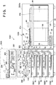
- Fig. 1 is a schematic view for explaining the system arrangement of a printer 1000 according to an embodiment.
- the printer 1000 adopts an arrangement of an electrophotographic method in this arrangement but may adopt another arrangement of an inkjet method or the like.
- the concept of a printer includes not only a printer that includes image formation or printing on a sheet as a main function but also a printer that includes this as an auxiliary function (for example, a multi-function printer or the like that further has a scanner function, a facsimile function, and the like). Therefore, the "printer" may be referred to as an image forming apparatus or an image forming system, or may be referred to as a printing apparatus or a printing system.
- the printer 1000 includes an apparatus main body 900, a scanner (reading apparatus) 2000, and a paper deck (feeding apparatus or sheet feeding apparatus) 3000.
- the apparatus main body 900 includes respective mechanisms for performing image formation and forms (prints) an image on each sheet S.
- the scanner 2000 reads an image on each sheet S, generates data according to the image (image data), and outputs the generated data to the apparatus main body 900.
- the paper deck 3000 is configured to be compatible with the sheets S of a plurality of sizes, can selectively store one of various kinds of sheets, and also feeds (or outputs) the sheet S of a target size to the apparatus main body 900, the details of which are to be described later.
- the apparatus main body 900 performs printing on the sheets S received from the paper deck 3000 or performs printing on the sheets S in the apparatus main body 900, and then discharges the printed sheets S.
- the apparatus main body 900 can also communicate with a general-purpose computer by wired communication (such as a LAN) or wireless communication (such as Wi-Fi) and perform printing based on resulting input image data.
- a sheet can be any printing medium capable of forming and printing an image, and paper of a predetermined size complying with a standard such as A3 or A4 is generally used. However, paper of a non-standard size may be used.
- the apparatus main body 900 includes an image forming unit 901, a sheet conveyance mechanism 902, a plurality of feeders 1001 to 1004, and a controller 120.
- the image forming unit 901 forms an image on each sheet S conveyed by the sheet conveyance mechanism 902.
- a mode in which the sheet conveyance mechanism 902 conveys the sheet S from the paper deck 3000 to the image forming unit 901 in the embodiment to be described later will be described.
- the sheet conveyance mechanism 902 can also convey the sheets S from the feeders 1001 to 1004 to the image forming unit 901.
- the controller 120 controls the operation of each element in the apparatus main body 900 so that printing in the apparatus main body 900 is implemented appropriately.
- the controller 120 may be configured to be able to implement a predetermined program by using a CPU (Central Processing Unit) and a memory, or may be implemented by a semiconductor device such as a PLD (Programmable Logic Device) or an ASIC (Application Specific Integrated Circuit). That is, control by the controller 120 can be implemented by either hardware or software.
- the image forming unit 901 includes a laser beam scanning unit 111, a photosensitive drum 112, a mirror 113, a developing unit 114, a transfer charger 115, a separation charger 116, a conveyance belt 117, a fixing unit 118, discharge rollers 119, and a discharge sensor 122.
- the laser beam scanning unit 111 outputs a laser beam based on image data from the scanner 2000. This laser beam is reflected by the mirror 113 and output from the laser beam scanning unit 111 such that reflected light from the mirror 113 scans the surface of the photosensitive drum 112. Consequently, a potential distribution is formed as a latent image on the surface of the photosensitive drum 112.
- the developing unit 114 applies toner to the surface of the photosensitive drum 112 and performs development based on the above-described potential distribution.
- the sheet conveyance mechanism 902 to be described later conveys each sheet S to a position 112a below the photosensitive drum 112.
- the transfer charger 115 transfers the toner on the surface of the photosensitive drum 112 to this sheet S in a transfer portion 112b. Consequently, an image is formed on the sheet S.
- This sheet S is separated from the photosensitive drum 112 by the separation charger 116, and then conveyed to the fixing unit 118 by the conveyance belt 117.
- the fixing unit 118 fixes the transferred toner to the sheet S.
- the discharge rollers 119 discharge this sheet S outside the apparatus main body 900.
- the discharge sensor 122 detects that the sheet S is discharged and outputs, for example, a signal indicating the completion of printing on one sheet to the controller 120.
- the sheet conveyance mechanism 902 includes pickup rollers 11, conveyance roller pairs 15, roller pairs 25 each being made up of a feed roller 22 and a retard roller 23, detection sensors 24, a sheet conveyance path 108, a preregistration roller pair 130, and a registration roller pair 110.
- a downstream side according to a conveyance direction may simply be expressed as a downstream side, and a side opposite to this may simply be expressed as an upstream side.
- Each pickup roller 11 is arranged in a corresponding one of the feeders 1001 to 1004, takes out the sheets S one by one from the corresponding feeder (1001 or the like), and conveys each sheet to the downstream side.
- Each roller pair 25 is arranged in a corresponding one of the feeders 1001 to 1004, conveys the sheets S taken out from the corresponding feeder one by one with the feed roller 22 and the retard roller 23, and if two or more sheets S are taken out, separates them from each other. More specifically, if one sheet S is taken out, the feed roller 22 and the retard roller 23 rotate in a direction of conveying the sheet S to the downstream side. If the two or more sheets S are taken out, the retard roller 23 rotates backward, and separates the two or more sheets S to convey one sheet S to the downstream side and return the sheets S other than this to the corresponding feeder.
- Each detection sensor 24 is arranged in a corresponding one of the feeders 1001 to 1004 and outputs a signal indicating passage of the sheet S to the controller 120.
- the conveyance roller pairs 15 are arranged in respective positions of the sheet conveyance path 108 and convey the sheet S from each of the feeders 1001 to 1004 to the downstream side.
- the preregistration roller pair 130 conveys each sheet S from one of the feeders 1001 to 1004 or each sheet S from the paper deck 3000 to be described later to the downstream side. Then, the registration roller pair 110 conveys this sheet S to the image forming unit 901 in synchronism with a print start timing by the image forming unit 901.
- Each paper feed cassette 10 is arranged in a corresponding one of the feeders 1001 to 1004, allowing a user to store the sheets S of a corresponding size in the paper feed cassette 10. Note that the sheets S of the same size may be stored in the feeders 1001 to 1004, or the sheets S of different sizes may be stored in some/all of them.
- the scanner 2000 includes a scanning light source 201, a platen glass 202, a pressing plate 203, a lens 204, a light-receiving element 205, a processor 206, a communication cable 207, a memory 208, and an auto document feeder 250.
- the scanning light source 201 irradiates, with light, an original (paper on which some image is formed, for example, a cutout from a magazine or the like) arranged on the platen glass 202 by the user and pressed by the pressing plate 203. Irradiation is performed such that this light scans the surface of the original.
- reflected light from the original is guided by a mirror, condensed by the lens 204, and then detected by the light-receiving element 205, as shown in Fig. 1 .
- the processor 206 Based on a detection result by the light-receiving element 205, the processor 206 generates image data based on the image on the original.
- the processor 206 can output this image data to the apparatus main body 900 via the communication cable 207 or store the data in the memory 208.
- the auto document feeder 250 is configured to capture them one by one in the scanner 2000. Consequently, the processor 206 generates image data based on the image on each original in accordance with the same procedure as described above.
- each of the apparatus main body 900 and the scanner 2000 is merely an example, and the printer 1000 is not limited to the above-described arrangement.
- the paper deck 3000 is connected to the apparatus main body 900 so as to be able to supply the sheet S and includes, in this embodiment, a paper feed mechanism 30, a controller 41, and a housing 3000a that incorporates them.
- the paper feed mechanism 30 includes a stacking mechanism 61 (stacking apparatus) configured to be able to stack the sheets S of various sizes and a storage 62 that stores the sheets S with the stacking mechanism 61.
- the stacking mechanism 61 includes a first stacking unit 61a serving as a main lifter and a second stacking unit 61b serving as an extension lifter.
- the second stacking unit 61b is arranged to be jointed to the first stacking unit 61a, the details of which are to be described later. For example, it is possible to stack the sheets S of a normal size (first size) by using the first stacking unit 61a. It is also possible to stack the sheets S of a large size (second size) by jointing the first stacking unit 61a and the second stacking unit 61b to each other to use the first and second stacking units 61a and 61b in common.
- first size first size
- second size large size
- a buffer member 81 may be arranged at a position to be the lower end of a movable region of the first stacking unit 61a on a base plate 63 of the storage 62.
- the sizes of the above-described sheets S may be expressed by the normal size/large size in order to facilitate the explanation in this specification.
- these merely indicate relative dimensions based on a use form of the stacking mechanism 61.
- the large size is an elongated size having a length (a length in the conveyance direction) of about 1.5 to 3 times larger than the normal size and can be used for, for example, an A4 two-page or four-page spread of a catalogue, pamphlet, POP (Point of Purchase) advertising, book jacket, or the like.
- the sheets S on the stacking mechanism 61 are pressed by a pressurization unit 84, making it possible to suppress floating of the stacked sheets S.
- An uppermost sheet out of the stacked sheets S is taken out by a pickup roller 51, and conveyed by a roller pair 31 made up of a feed roller 12 and a retard roller 13 to a connecting conveyance path 32.
- the connecting conveyance path 32 is connected to the sheet conveyance path 108 in the apparatus main body 900. Consequently, the sheet S conveyed to the connecting conveyance path 32 is conveyed to the sheet conveyance path 108, and then conveyed to the image forming unit 901 by the preregistration roller pair 130 and the registration roller pair 110. From this viewpoint, the connecting conveyance path 32 corresponds to an output unit that outputs the sheet S to the apparatus main body 900.
- the function of the pickup roller 51 is the same as that of each pickup roller 11. Further, the functions of the feed roller 12 and retard roller 13 are, respectively, the same as those of feed rollers 22 and retard rollers 23 of the roller pair 31.
- Fig. 2 is a block diagram for explaining the details of the system arrangement of the paper deck 3000.
- the paper deck 3000 includes a driver 45 and a storage lock solenoid 46.
- the storage 62 can be locked by a solenoid lock method.
- the controller 41 drives the storage lock solenoid 46 by the driver 45, locking the storage 62 (restricting opening of the storage 62) or releasing the lock (making it possible to open the storage 62).
- the paper deck 3000 further includes an I/O interface 42, a motor driver 43, various motors 44, a motor driver 53, and a driving mechanism 54. These are arranged in the paper feed mechanism 30.
- the controller 41 drives the various motors 44 by, for example, the motor driver 43 via the I/O interface 42, rotating the pickup roller 51.
- the controller 41 also drives, for example, the motor driver 53 via the I/O interface 42, driving the driving mechanism 54.
- the driving mechanism 54 includes an up-and-down movement motor 55 or the like serving as a power source and functions as an up-and-down movement driving unit that moves up and down the first stacking unit 61a serving as the main lifter in a vertical direction, the details of which are to be described later. With this arrangement, the controller 41 drives the up-and-down movement motor 55 by using the motor driver 53, and controls up-and-down movement of the first stacking unit 61a.
- the paper deck 3000 further includes a storage opening/closing button 306. If the user presses the storage opening/closing button 306 in an operation state in which opening of the storage 62 is permitted (for example, a state in which printing is not performed in the apparatus main body 900), a signal 75 indicating that there is an open request of the storage 62 is input to the controller 41. In response to this, the controller 41 drives the storage lock solenoid 46 by the driver 45 to release the lock of the storage 62 and open the storage 62.
- the paper deck 3000 further includes a plurality of sensors 48 to 50 and 300 to 302. Detection results of these sensors 48 to 50 and 300 to 302 are input to the controller 41 by signals 69 indicating the detection results. In response to this, the controller 41 mainly controls the operation of each element of the paper feed mechanism 30 in the paper deck 3000.
- the relay sensor 48 is one of sensors for detecting the position of the first stacking unit 61a and is a sensor for moving the first stacking unit 61a to a position where the user replenishes the sheets S easily when the storage 62 is opened.
- the storage opening/closing sensor 49 is a sensor for detecting whether the storage 62 is set in an open state or a closed state.
- the paper surface detection sensor 50 is a sensor for detecting the uppermost position of the sheets S stacked on the stacking mechanism 61.
- the paper presence/absence sensor 300 is a sensor for detecting the presence/absence of the sheets S on the stacking mechanism 61.
- the lower limit detection sensor 301 is a sensor for detecting whether the first stacking unit 61a is located at the lower end of the movable region.
- the guide unit detection sensor 302 is a sensor for detecting the size of each sheet S, the details of which are to be described later.
- controller 41 controls the operation of each element in the paper feed mechanism 30 so that paper feed by the paper feed mechanism 30 is implemented appropriately.
- control by the controller 41 can be implemented by either hardware or software.
- the paper deck 3000 can perform signal communication with the apparatus main body 900 by the controller 41 and can, for example, accept a paper feed request from the apparatus main body 900 and establish synchronization for a print start timing, a paper feed timing, or the like.
- the apparatus main body 900 accepts a print job from the user via an operation panel 40.
- the apparatus main body 900 can also notify the user of information (for example, a need to replenish the sheets S, a need to exchange toner, occurrence of paper jam, or the like) needed for printing via the operation panel 40.
- the operation panel 40 can be provided at a position easily viewable by the user, for example, in the upper portion of the apparatus main body 900.
- Fig. 3 is a perspective view showing the internal structure, or mainly the paper feed mechanism 30 of the paper deck 3000.
- the pickup roller 51 rotates in an a direction
- the uppermost sheet S stacked on the stacking mechanism 61 is taken out in a b direction, starting conveyance of the sheet S.
- the sheet S is conveyed to the connecting conveyance path 32 by rotating the feed roller 12 in a c direction and further conveyed to the downstream side by rotating the preregistration roller pair 130 in a d direction.
- the paper feed mechanism 30 further includes a leading end guide unit 86 on one-end side, that is, the downstream side in the b direction and still further includes a trailing end guide unit (first guide unit) 87 on the other-end side, that is, the upstream side.
- the leading end guide unit 86 is a plate member that forms the side surface portion of the storage 62.
- the trailing end guide unit 87 is a columnar member arranged such that its position can be adjusted in the b direction. With these guide units 86 and 87, it is possible to guide a sheet length or align a bundle of the sheets S stacked on the stacking mechanism 61.
- the paper feed mechanism 30 further includes side edge guide units (second guide units) 80 and 83 on both sides in the h direction.
- a pair of side edge guide units 80 are arranged so as to sandwich the sheets S from lateral sides on the downstream side.
- a pair of side edge guide units 83 are arranged on the upstream side.
- the side edge guide units 80 and 83 are arranged such that their positions can be adjusted in the h direction.
- the side edge guide units 80 can move a part of a stacking region of the sheets S by the first stacking unit 61a in the h direction
- the side edge guide units 83 can move a part of a stacking region of the sheets S by the second stacking unit 61b in the h direction. This makes it possible to guide a sheet width or align the bundle of the sheets S stacked on the stacking mechanism 61.
- the side edge guide units 80 and 83 may be referred to as width guide units, sheet width guide units, or the like. Movable ranges of the side edge guide units 80 and 83 in the h direction may be changed based on the position of the trailing end guide unit 87 in the b direction. For example, if the sheets S of the normal size are stacked, the trailing end guide unit 87 is located on the downstream side of the pair of side edge guide units 83, and the pair of these side edge guide units 83 can move to a position where they come close to each other.
- the respective guide units 80, 83, 86, and 87 described above may collectively be expressed as a guide mechanism, a guide member, or the like.
- Fig. 4 is a side view showing the paper feed mechanism 30. A state in which the sheets S are not stacked is shown here in order to explain the structure of the stacking mechanism 61 in detail.
- the stacking mechanism 61 includes the first stacking unit 61a serving as the main lifter and the second stacking unit 61b serving as the extension lifter.
- Fig. 4 shows a state in which the first stacking unit 61a is located at the lower end of its movable region.
- the first stacking unit 61a includes a thin portion 61a' on the upstream side.
- the second stacking unit 61b is arranged to be jointed to the first stacking unit 61a by overlapping the portion 61a' (the first and second stacking units 61a and 61b are arranged to be jointed to each other). That is, the portion 61a' functions as a joint unit that implements a joint to the second stacking unit 61b.
- the second stacking unit 61b is fixed to a position at a predetermined height from the base plate 63, or here a position (first position) P1 above the base plate 63 by a predetermined distance by being supported by a support unit 305 in a state in which it is not jointed to the first stacking unit 61a.
- the driving mechanism 54 further includes a driving pulley 90, a plurality of guide pulleys 91, and a plurality of wires 92a to 92c (lifting members), in addition to the up-and-down movement motor 55.
- the driving pulley 90 is arranged to be coaxial with the rotation shaft of the up-and-down movement motor 55.
- the plurality of guide pulleys 91 are arranged so as to guide the wires 92a to 92c to respective positions capable of fixing the first stacking unit 61a.
- the wire 92a is fixed to the downstream-side edge portion of the first stacking unit 61a.
- the wire 92b is fixed to the central portion of the first stacking unit 61a.
- the wire 92c is fixed to the upstream-side edge portion of the first stacking unit 61a (the thin portion 61a' thereof).
- the driving pulley 90 rotates when the up-and-down movement motor 55 rotates, and the rotation is transmitted to the first stacking unit 61a via the respective wires 92a to 92c.
- the driving force of the up-and-down movement motor 55 is transmitted to the first stacking unit 61a directly/indirectly and, for example, the first stacking unit 61a is raised when the up-and-down movement motor 55 rotates in one direction, and the first stacking unit 61a is lowered when the up-and-down movement motor 55 rotates in the other direction.
- the wires 92a to 92c are, respectively, fixed to the downstream-side edge portion, central portion, and upstream-side edge portion of the first stacking unit 61a, making it possible to move up and down the first stacking unit 61a while maintaining its orientation horizontal and suppressing its distortion.
- the first stacking unit 61a is configured to support the second stacking unit 61b if the second stacking unit 61b is jointed, the details of which are to be described later. Accordingly, if the first stacking unit 61a is fixed at a plurality of positions by the wire 92a and the like as in this embodiment, these fixing positions preferably include at least two points on an upstream side and a downstream side with respect to the barycenter of the second stacking unit 61b in the b direction.
- the barycenter of the second stacking unit 61b is indicated by an alternate long and short dashed line in Fig. 4 .
- the driving pulleys 90, the plurality of guide pulleys 91, and the wires 92a to 92c described above are provided on the both sides in the h direction.
- the wires 92a to 92c can be anything capable of transmitting the driving force of the up-and-down movement motor 55.
- wires other string-like, belt-like, or chain-like transmission members, for example, cables, belts, chains, or the like may be used for these.
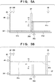
- FIG. 5A shows a structure in a state in which the first stacking unit 61a is located in a first region R1 below the position P1, and the second stacking unit 61b is fixed to the position P1.
- the trailing end guide unit 87 is located on the downstream side of the support unit 305 (or on the downstream side of the second stacking unit 61b). In this state, the sheets S of the normal size (for example, an A3 or A4 size) can be stacked on the first stacking unit 61a.
- Fig. 5B shows a structure in a state in which the first stacking unit 61a is located in a second region R2 above the position P1, and the second stacking unit 61b is jointed to the first stacking unit 61a.
- the trailing end guide unit 87 is located on the upstream side of the support unit 305 (or below the second stacking unit 61b).
- the sheets S of the large size for example, a non-standard size longer than the normal size
- the user can adjust the position of the trailing end guide unit 87 in the b direction, stack the sheets S of the normal size by moving the trailing end guide unit 87 to the downstream side, and stack the sheets S of the large size by moving the trailing end guide unit 87 to the upstream side.
- the first stacking unit 61a can move up and down using both the first and second regions R1 and R2 as movable regions.
- the second stacking unit 61b is held at the position P1 if the first stacking unit 61a is in the first region R1, and can move up and down together with the first stacking unit 61a while being jointed to the portion 61a' of the first stacking unit 61a if the first stacking unit 61a is in the second region R2.
- the second stacking unit 61b is jointed to the first stacking unit 61a in synchronism with the raising operation of the first stacking unit 61a, and released from the joint in synchronism with the lowering operation of the first stacking unit 61a.
- the position P1 is a position higher than a lower limit position at which the first stacking unit 61a can be lowered, and lower than an upper limit position at which the first and second stacking units 61a and 61b can be raised.
- the second stacking unit 61b is juxtaposed with a portion of the first stacking unit 61a capable of stacking the sheets S of the normal size in the b direction (that is, a direction parallel to the long sides of the sheets S of the large size).
- the weight of one sheet S is larger in the large size than in the normal size. Then, according to this embodiment, if the sheets S of the normal size are stacked, the lower end of the movable region of the first stacking unit 61 a is below the position P1. On the other hand, if the sheets S of the large size are stacked, the lower end of the movable region of the first stacking unit 61a (and the second stacking unit 61b) is at the position P1. Accordingly, the maximum stacking number (for example, 1,500) of sheets S of the large size becomes smaller than the maximum stacking number (for example, 3,000) of sheets S of the normal size.
- the maximum stacking number for example, 1,500
- an excessive load is not applied to the up-and-down movement motor 55 even if the sheets S of the large size are stacked.
- the stacking amount of the sheets S of the large size becomes the largest in a state in which the first and second stacking units 61a and 61b are fixed to the position P1.
- the guide unit detection sensor 302 acts as a detection unit capable of detecting whether the size of the sheets S to be stacked is one of the normal size and the large size depending on the position of the trailing end guide unit 87. Based on a detection result by the guide unit detection sensor 302, the controller 41 can measure the size of each sheet S, for example, can decide the conveyance distance of the sheet S by the pickup roller 51.
- Fig. 6A is a plan view showing the paper feed mechanism 30 corresponding to Fig. 5A .
- Fig. 6B is a plan view showing the paper feed mechanism 30 corresponding to Fig. 5B .
- the stacking mechanism 61 includes an elongated hole portion 61c extending in the b direction, and the trailing end guide unit 87 can move in the b direction in the elongated hole portion 61c.
- the first stacking unit 61a has a fence-like shape that includes, in a planar view (in a perspective in the vertical direction), a wide portion extending in the b direction and a plurality of narrow portions extending in the h direction from this wide portion. This allows the side edge guide units 80 and 83 to be arranged apart from the first stacking unit 61a in the h direction and to move in the h direction while preventing a deflection of each stacked sheet S. Note that the width of the wide portion in the h direction is wider than the width of each narrow portion in the b direction, and the above-described elongated hole portion 61c is provided in this wide portion.
- the second stacking unit 61b is provided so as to overlap a part of the first stacking unit 61a on the upstream side, here the thin portion 61a' in the planar view.
- the second stacking unit 61b is jointed to the first stacking unit 61a when the first stacking unit 61a is raised to the position P1, and then can move up and down in the second region R2 above the position P1 together with the first stacking unit 61a.
- the second stacking unit 61b has a fence-like shape similar to the first stacking unit 61a, allowing the side edge guide units 83 to be arranged apart from the first and second stacking units 61a and 61b in the h direction, and to move in the h direction.
- the above-described elongated hole portion 61c is illustrated as one rectangular hole in each of Figs. 6A and 6B , but is formed to be provided in both the first stacking unit 61a and the second stacking unit 61b. That is, in the planar view, one hole is provided over both of a portion which overlaps the second stacking unit 61b and a portion which does not overlap the second stacking unit 61b concerning the first stacking unit 61a, and a portion which overlaps the first stacking unit 61a concerning the second stacking unit 61b. This allows the trailing end guide unit 87 to move in the b direction.
- Figs. 7A and 7B are perspective views each for explaining the internal structure, or mainly the housing 3000a and storage 62 of the paper deck 3000.
- Fig. 7A is the perspective view in a state in which the storage 62 is closed.
- Fig. 7B is the perspective view in a state in which the storage 62 is opened.
- the controller 41 opens the storage 62 in response to pressing of the storage opening/closing button 306 by the user.
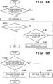
- Figs. 8A and 8B are flowcharts for explaining a method of using the paper deck 3000. Contents of respective steps in these flowcharts are mainly performed by the controller 41.
- the flowchart of Fig. 8A shows a method of setting the size of the sheet S that can be stored in the storage 62. In this flowchart, the user can set the size of the sheet S by adjusting the position of the trailing end guide unit 87 after the storage 62 is opened.
- step S100 the controller 41 determines whether the storage opening/closing button 306 (see Fig. 2 ) is pressed. If the button 306 is pressed by, for example, the user, the process advances to S110; otherwise, the process returns to S100. In S110, the controller 41 opens the storage 62 in response to pressing of the button 306.
- the controller 41 determines whether the storage 62 is closed by the user. If the storage 62 is closed by, for example, the user, this flowchart ends; otherwise, the process advances to S130. It is possible to implement S120 by a detection result of the storage opening/closing sensor 49 (see Fig. 2 ).
- the controller 41 determines whether the position of the trailing end guide unit 87 is changed. If the position of the trailing end guide unit 87 is changed, the process advances to S140; otherwise, the process returns to S120. It is possible to implement S130 based on a detection result of the guide unit detection sensor 302 (see Figs. 2 , 5A, and 5B ).
- an operation mode is set based on the change in position of the trailing end guide unit 87, that is, based on the size of the sheet S to be stored or conveyed newly. For example, adjustment of the conveyance distance of the sheet S, or adjustment of the rotation amounts of the pickup roller 51 and roller pair 31 in this embodiment is performed.
- the flowchart of Fig. 8B shows an example of a method of setting the operation mode in S140.
- the controller 41 determines whether the position of the trailing end guide unit 87 satisfies a predetermined condition.
- the process advances to S1402 if the trailing end guide unit 87 is located on the downstream side of the support unit 305; otherwise, the process advances to S1403.
- the controller 41 sets the operation mode to a normal size paper mode. If the trailing end guide unit 87 is located on the downstream of the support unit 305, the sheets S of the normal size are stacked on the first stacking unit 61a regardless of a joint to the second stacking unit 61b (regardless of whether the first stacking unit 61a is located in one of the first and second regions R1 and R2). In the normal size paper mode, the first stacking unit 61a is lowered to a predetermined position in the first region R1 so as to, for example, make it easier for the user to stack the sheets S of the normal size in the state in which the storage 62 is opened.
- the controller 41 sets the operation mode to a large size paper mode. If the trailing end guide unit 87 is located on the upstream side of the support unit 305, the movable region of the first stacking unit 61a is restricted only to the second region R2. Then, the first stacking unit 61a and the second stacking unit 61b are jointed to each other, and the sheets S of the large size are stacked on them. In the large size paper mode, the first stacking unit 61a is moved to the lower end of the second region R2, that is, the position P1 so as to, for example, make it easier for the user to stack the sheets S of the large size in the state in which the storage 62 is opened.
- the side edge guide units 83 may be configured to move to a home position (for example, a position that does not allow the sheets S of the large size to be stacked) in the normal size paper mode (if the trailing end guide unit 87 is located on the downstream side).
- a home position for example, a position that does not allow the sheets S of the large size to be stacked
- the controller 41 may notify the user that the stacking should be stopped by displaying this on the operation panel 40. Further, if the operation mode is changed, the controller 41 may notify the user that the sheets S of a size before the change should be removed from the stacking mechanism 61. These notifications may be made by another notification unit using a sound, light, or the like.
- the paper deck 3000 includes the first stacking unit 61a, the second stacking unit 61b arranged to be jointed to the first stacking unit, and the driving mechanism 54 functioning as the up-and-down movement driving unit.
- the sheets S of the normal size can be stacked on the first stacking unit 61a.
- the second stacking unit 61b joints to the first stacking unit 61a, making it possible to stack the sheets S of the large size together with the first stacking unit 61a.
- the driving mechanism 54 moves up and down the first stacking unit 61a in the vertical direction.
- the second stacking unit 61b is fixed to the position P1 if the first stacking unit 61a moves up and down in the first region R1 lower than the position P1.
- the second stacking unit 61b joints to the first stacking unit 61a, and moves up and down together with the first stacking unit 61a if the first stacking unit 61a moves up and down in the second region R2 higher than the position P1.
- the sheets S of the normal size are stored in the paper deck 3000, the sheets S of the normal size are stacked on the first stacking unit 61a.
- the sheets S of the large size are stored in the paper deck 3000, the sheets S of the large size are stacked on the first and second stacking units 61a and 61b jointed to each other. According to this arrangement, with a comparatively simple arrangement, it becomes possible to move up and down the first stacking unit 61a in addition to the second stacking unit 61b without providing, for example, the plurality of vertical movement motors 55 of the driving mechanism 54.
- the mass of one sheet S of the large size is larger than the mass of one sheet S of the normal size.
- the movable region of the second stacking unit 61b is above the position P1, that is, the second region R2. Accordingly, the maximum stacking number if the sheets S of the large size are stacked on the first and second stacking units 61a and 61b is smaller than the maximum stacking number if the sheets S of the normal size are stacked on the first stacking unit 61a. Therefore, the sheets S of the large size are not stored in the paper deck 3000 excessively, and thus the excessive load is not applied to the driving mechanism 54 (for example, the up-and-down movement motor 55).
- a behavior mode of the second stacking unit 61b if the first stacking unit 61a is in the first region R1 and a behavior mode of the second stacking unit 61b if the first stacking unit 61a is in the second region R2 may be changed to be reversed.
- the second stacking unit 61b may be held at a predetermined height (for example, the position PI) if the first stacking unit 61a is in the second region R2, and may be jointed to the first stacking unit 61a and movable up and down together with the first stacking unit 61a if the first stacking unit 61a is in the first region R1.
- the paper feed mechanism 30 is configured to, for example, supply the bundle of the stacked sheets S sequentially from the lowermost sheet to the apparatus main body 900.
- a stacking apparatus comprising a first stacking unit, for stacking sheets of a first size, configured to move vertically between an upper limit position and a lower limit position, and a second stacking unit for stacking sheets of a second size larger than the first size in cooperation with the first stacking unit, the second stacking unit being jointed to the first stacking unit at a predetermined position, moving vertically together with the first stacking unit while being jointed to the first stacking unit above the predetermined position, and being released from a joint to the first stacking unit below the predetermined position.
Landscapes
- Engineering & Computer Science (AREA)
- Mechanical Engineering (AREA)
- Sheets, Magazines, And Separation Thereof (AREA)
- Paper Feeding For Electrophotography (AREA)
- Pile Receivers (AREA)
Description
- The present invention relates to a stacking apparatus, a feeding apparatus, and an image forming apparatus.
- Japanese Patent Laid-Open No.
2003-63719 2003-63719 2003-63719 2003-63719 - According to the structure in Japanese Patent Laid-Open No.
2003-63719 - The present invention implements, in a stacking apparatus that stacks sheets of a plurality of sizes on a plurality of stacking units, a stacking apparatus capable of synchronizing the respective stacking units with a simple arrangement.
- The present invention in its first aspect provides a stacking apparatus as specified in
claims 1 to 14. - The present invention in its second aspect provides a feeding apparatus as specified in
claim 15 or 16. - The present invention in its third aspect provides an image forming apparatus as specified in claim 17.
- The present invention in its fourth aspect provides a stacking apparatus as specified in claim 18.
- Further features of the present invention will become apparent from the following description of exemplary embodiments with reference to the attached drawings.
-
-
Fig. 1 is a schematic view for explaining an example of the structure of a printer; -
Fig. 2 is a block diagram for explaining an example of a system arrangement of a paper deck; -
Fig. 3 is a perspective view for explaining an example of the internal structure of the paper deck; -
Fig. 4 is a side view for explaining an example of the internal structure of the paper deck; -
Figs. 5A and 5B are side views each for explaining the behavior of a stacking mechanism; -
Figs. 6A and 6B are plan views each for explaining an example of the internal structure of the paper deck; -
Figs. 7A and 7B are perspective views each for explaining an example of the internal structure of the paper deck; and -
Figs. 8A and 8B are flowcharts each for explaining a method of using the paper deck. - A preferred embodiment of the present invention will be described below with reference to the accompanying drawings. Note that the drawings are schematic views illustrated for the purpose of only explaining structures or arrangements, and the sizes of illustrated members do not always reflect actual sizes. In addition, the same reference numerals denote the same members or same constituent elements throughout the drawings, and a description of repetitive contents will be omitted hereinafter.
-
Fig. 1 is a schematic view for explaining the system arrangement of aprinter 1000 according to an embodiment. Theprinter 1000 adopts an arrangement of an electrophotographic method in this arrangement but may adopt another arrangement of an inkjet method or the like. - The concept of a printer includes not only a printer that includes image formation or printing on a sheet as a main function but also a printer that includes this as an auxiliary function (for example, a multi-function printer or the like that further has a scanner function, a facsimile function, and the like). Therefore, the "printer" may be referred to as an image forming apparatus or an image forming system, or may be referred to as a printing apparatus or a printing system.
- In this embodiment, the
printer 1000 includes an apparatusmain body 900, a scanner (reading apparatus) 2000, and a paper deck (feeding apparatus or sheet feeding apparatus) 3000. The apparatusmain body 900 includes respective mechanisms for performing image formation and forms (prints) an image on each sheet S. Thescanner 2000 reads an image on each sheet S, generates data according to the image (image data), and outputs the generated data to the apparatusmain body 900. Thepaper deck 3000 is configured to be compatible with the sheets S of a plurality of sizes, can selectively store one of various kinds of sheets, and also feeds (or outputs) the sheet S of a target size to the apparatusmain body 900, the details of which are to be described later. - For example, based on the image data from the
scanner 2000, the apparatusmain body 900 performs printing on the sheets S received from thepaper deck 3000 or performs printing on the sheets S in the apparatusmain body 900, and then discharges the printed sheets S. Moreover, the apparatusmain body 900 can also communicate with a general-purpose computer by wired communication (such as a LAN) or wireless communication (such as Wi-Fi) and perform printing based on resulting input image data. - In this specification, the concept of an image includes not only visually recognizable information such as a character, symbol, pattern, figure, picture, and photograph but also includes a blank (a region which is practically the same as the ground color of the paper surface). A sheet can be any printing medium capable of forming and printing an image, and paper of a predetermined size complying with a standard such as A3 or A4 is generally used. However, paper of a non-standard size may be used.
- The apparatus
main body 900 includes animage forming unit 901, asheet conveyance mechanism 902, a plurality offeeders 1001 to 1004, and acontroller 120. Theimage forming unit 901 forms an image on each sheet S conveyed by thesheet conveyance mechanism 902. A mode in which thesheet conveyance mechanism 902 conveys the sheet S from thepaper deck 3000 to theimage forming unit 901 in the embodiment to be described later will be described. However, thesheet conveyance mechanism 902 can also convey the sheets S from thefeeders 1001 to 1004 to theimage forming unit 901. - The
controller 120 controls the operation of each element in the apparatusmain body 900 so that printing in the apparatusmain body 900 is implemented appropriately. For example, thecontroller 120 may be configured to be able to implement a predetermined program by using a CPU (Central Processing Unit) and a memory, or may be implemented by a semiconductor device such as a PLD (Programmable Logic Device) or an ASIC (Application Specific Integrated Circuit). That is, control by thecontroller 120 can be implemented by either hardware or software. - The
image forming unit 901 includes a laserbeam scanning unit 111, aphotosensitive drum 112, amirror 113, a developingunit 114, atransfer charger 115, aseparation charger 116, aconveyance belt 117, afixing unit 118,discharge rollers 119, and adischarge sensor 122. The laserbeam scanning unit 111 outputs a laser beam based on image data from thescanner 2000. This laser beam is reflected by themirror 113 and output from the laserbeam scanning unit 111 such that reflected light from themirror 113 scans the surface of thephotosensitive drum 112. Consequently, a potential distribution is formed as a latent image on the surface of thephotosensitive drum 112. - The developing
unit 114 applies toner to the surface of thephotosensitive drum 112 and performs development based on the above-described potential distribution. Note that thesheet conveyance mechanism 902 to be described later conveys each sheet S to aposition 112a below thephotosensitive drum 112. Thetransfer charger 115 transfers the toner on the surface of thephotosensitive drum 112 to this sheet S in atransfer portion 112b. Consequently, an image is formed on the sheet S. This sheet S is separated from thephotosensitive drum 112 by theseparation charger 116, and then conveyed to thefixing unit 118 by theconveyance belt 117. Thefixing unit 118 fixes the transferred toner to the sheet S. Subsequently, thedischarge rollers 119 discharge this sheet S outside the apparatusmain body 900. Thedischarge sensor 122 detects that the sheet S is discharged and outputs, for example, a signal indicating the completion of printing on one sheet to thecontroller 120. - The
sheet conveyance mechanism 902 includespickup rollers 11,conveyance roller pairs 15, roller pairs 25 each being made up of a feed roller 22 and a retard roller 23,detection sensors 24, asheet conveyance path 108, apreregistration roller pair 130, and aregistration roller pair 110. Note that in a description below, a downstream side according to a conveyance direction (or a feeding direction) may simply be expressed as a downstream side, and a side opposite to this may simply be expressed as an upstream side. - Each
pickup roller 11 is arranged in a corresponding one of thefeeders 1001 to 1004, takes out the sheets S one by one from the corresponding feeder (1001 or the like), and conveys each sheet to the downstream side. Each roller pair 25 is arranged in a corresponding one of thefeeders 1001 to 1004, conveys the sheets S taken out from the corresponding feeder one by one with the feed roller 22 and the retard roller 23, and if two or more sheets S are taken out, separates them from each other. More specifically, if one sheet S is taken out, the feed roller 22 and the retard roller 23 rotate in a direction of conveying the sheet S to the downstream side. If the two or more sheets S are taken out, the retard roller 23 rotates backward, and separates the two or more sheets S to convey one sheet S to the downstream side and return the sheets S other than this to the corresponding feeder. - Each
detection sensor 24 is arranged in a corresponding one of thefeeders 1001 to 1004 and outputs a signal indicating passage of the sheet S to thecontroller 120. The conveyance roller pairs 15 are arranged in respective positions of thesheet conveyance path 108 and convey the sheet S from each of thefeeders 1001 to 1004 to the downstream side. - The
preregistration roller pair 130 conveys each sheet S from one of thefeeders 1001 to 1004 or each sheet S from thepaper deck 3000 to be described later to the downstream side. Then, theregistration roller pair 110 conveys this sheet S to theimage forming unit 901 in synchronism with a print start timing by theimage forming unit 901. - Each
paper feed cassette 10 is arranged in a corresponding one of thefeeders 1001 to 1004, allowing a user to store the sheets S of a corresponding size in thepaper feed cassette 10. Note that the sheets S of the same size may be stored in thefeeders 1001 to 1004, or the sheets S of different sizes may be stored in some/all of them. - The
scanner 2000 includes ascanning light source 201, aplaten glass 202, apressing plate 203, alens 204, a light-receivingelement 205, aprocessor 206, acommunication cable 207, amemory 208, and anauto document feeder 250. Thescanning light source 201 irradiates, with light, an original (paper on which some image is formed, for example, a cutout from a magazine or the like) arranged on theplaten glass 202 by the user and pressed by thepressing plate 203. Irradiation is performed such that this light scans the surface of the original. - In this embodiment, reflected light from the original is guided by a mirror, condensed by the
lens 204, and then detected by the light-receivingelement 205, as shown inFig. 1 . Based on a detection result by the light-receivingelement 205, theprocessor 206 generates image data based on the image on the original. Theprocessor 206 can output this image data to the apparatusmain body 900 via thecommunication cable 207 or store the data in thememory 208. - If the user places one or more originals, the
auto document feeder 250 is configured to capture them one by one in thescanner 2000. Consequently, theprocessor 206 generates image data based on the image on each original in accordance with the same procedure as described above. - Note that the arrangement of each of the apparatus
main body 900 and thescanner 2000 is merely an example, and theprinter 1000 is not limited to the above-described arrangement. - The
paper deck 3000 is connected to the apparatusmain body 900 so as to be able to supply the sheet S and includes, in this embodiment, apaper feed mechanism 30, acontroller 41, and ahousing 3000a that incorporates them. In this embodiment, thepaper feed mechanism 30 includes a stacking mechanism 61 (stacking apparatus) configured to be able to stack the sheets S of various sizes and astorage 62 that stores the sheets S with the stackingmechanism 61. - The stacking
mechanism 61 includes a first stackingunit 61a serving as a main lifter and a second stackingunit 61b serving as an extension lifter. The second stackingunit 61b is arranged to be jointed to the first stackingunit 61a, the details of which are to be described later. For example, it is possible to stack the sheets S of a normal size (first size) by using the first stackingunit 61a. It is also possible to stack the sheets S of a large size (second size) by jointing the first stackingunit 61a and the second stackingunit 61b to each other to use the first and second stackingunits Fig. 1 shows a mode in which the sheets S of the large size are stacked by using both the first and second stackingunits paper deck 3000. Abuffer member 81 may be arranged at a position to be the lower end of a movable region of the first stackingunit 61a on abase plate 63 of thestorage 62. - Note that the sizes of the above-described sheets S may be expressed by the normal size/large size in order to facilitate the explanation in this specification. However, these merely indicate relative dimensions based on a use form of the stacking
mechanism 61. For example, the large size is an elongated size having a length (a length in the conveyance direction) of about 1.5 to 3 times larger than the normal size and can be used for, for example, an A4 two-page or four-page spread of a catalogue, pamphlet, POP (Point of Purchase) advertising, book jacket, or the like. - The sheets S on the stacking
mechanism 61 are pressed by apressurization unit 84, making it possible to suppress floating of the stacked sheets S. An uppermost sheet out of the stacked sheets S is taken out by apickup roller 51, and conveyed by aroller pair 31 made up of afeed roller 12 and aretard roller 13 to a connectingconveyance path 32. The connectingconveyance path 32 is connected to thesheet conveyance path 108 in the apparatusmain body 900. Consequently, the sheet S conveyed to the connectingconveyance path 32 is conveyed to thesheet conveyance path 108, and then conveyed to theimage forming unit 901 by thepreregistration roller pair 130 and theregistration roller pair 110. From this viewpoint, the connectingconveyance path 32 corresponds to an output unit that outputs the sheet S to the apparatusmain body 900. - Note that the function of the
pickup roller 51 is the same as that of eachpickup roller 11. Further, the functions of thefeed roller 12 andretard roller 13 are, respectively, the same as those of feed rollers 22 and retard rollers 23 of theroller pair 31. -
Fig. 2 is a block diagram for explaining the details of the system arrangement of thepaper deck 3000. Thepaper deck 3000 includes adriver 45 and astorage lock solenoid 46. Thestorage 62 can be locked by a solenoid lock method. Thecontroller 41 drives thestorage lock solenoid 46 by thedriver 45, locking the storage 62 (restricting opening of the storage 62) or releasing the lock (making it possible to open the storage 62). - The
paper deck 3000 further includes an I/O interface 42, amotor driver 43,various motors 44, amotor driver 53, and adriving mechanism 54. These are arranged in thepaper feed mechanism 30. Thecontroller 41 drives thevarious motors 44 by, for example, themotor driver 43 via the I/O interface 42, rotating thepickup roller 51. - The
controller 41 also drives, for example, themotor driver 53 via the I/O interface 42, driving thedriving mechanism 54. Thedriving mechanism 54 includes an up-and-downmovement motor 55 or the like serving as a power source and functions as an up-and-down movement driving unit that moves up and down the first stackingunit 61a serving as the main lifter in a vertical direction, the details of which are to be described later. With this arrangement, thecontroller 41 drives the up-and-downmovement motor 55 by using themotor driver 53, and controls up-and-down movement of the first stackingunit 61a. - The
paper deck 3000 further includes a storage opening/closing button 306. If the user presses the storage opening/closing button 306 in an operation state in which opening of thestorage 62 is permitted (for example, a state in which printing is not performed in the apparatus main body 900), asignal 75 indicating that there is an open request of thestorage 62 is input to thecontroller 41. In response to this, thecontroller 41 drives thestorage lock solenoid 46 by thedriver 45 to release the lock of thestorage 62 and open thestorage 62. - The
paper deck 3000 further includes a plurality ofsensors 48 to 50 and 300 to 302. Detection results of thesesensors 48 to 50 and 300 to 302 are input to thecontroller 41 bysignals 69 indicating the detection results. In response to this, thecontroller 41 mainly controls the operation of each element of thepaper feed mechanism 30 in thepaper deck 3000. - The
relay sensor 48 is one of sensors for detecting the position of the first stackingunit 61a and is a sensor for moving the first stackingunit 61a to a position where the user replenishes the sheets S easily when thestorage 62 is opened. The storage opening/closing sensor 49 is a sensor for detecting whether thestorage 62 is set in an open state or a closed state. The papersurface detection sensor 50 is a sensor for detecting the uppermost position of the sheets S stacked on the stackingmechanism 61. - The paper presence/
absence sensor 300 is a sensor for detecting the presence/absence of the sheets S on the stackingmechanism 61. The lowerlimit detection sensor 301 is a sensor for detecting whether the first stackingunit 61a is located at the lower end of the movable region. The guideunit detection sensor 302 is a sensor for detecting the size of each sheet S, the details of which are to be described later. - With the above arrangement, the
controller 41 controls the operation of each element in thepaper feed mechanism 30 so that paper feed by thepaper feed mechanism 30 is implemented appropriately. Similarly to thecontroller 120, control by thecontroller 41 can be implemented by either hardware or software. - The
paper deck 3000 can perform signal communication with the apparatusmain body 900 by thecontroller 41 and can, for example, accept a paper feed request from the apparatusmain body 900 and establish synchronization for a print start timing, a paper feed timing, or the like. The apparatusmain body 900 accepts a print job from the user via anoperation panel 40. The apparatusmain body 900 can also notify the user of information (for example, a need to replenish the sheets S, a need to exchange toner, occurrence of paper jam, or the like) needed for printing via theoperation panel 40. Note that theoperation panel 40 can be provided at a position easily viewable by the user, for example, in the upper portion of the apparatusmain body 900. -
Fig. 3 is a perspective view showing the internal structure, or mainly thepaper feed mechanism 30 of thepaper deck 3000. When thepickup roller 51 rotates in an a direction, the uppermost sheet S stacked on the stackingmechanism 61 is taken out in a b direction, starting conveyance of the sheet S. The sheet S is conveyed to the connectingconveyance path 32 by rotating thefeed roller 12 in a c direction and further conveyed to the downstream side by rotating thepreregistration roller pair 130 in a d direction. - The
paper feed mechanism 30 further includes a leadingend guide unit 86 on one-end side, that is, the downstream side in the b direction and still further includes a trailing end guide unit (first guide unit) 87 on the other-end side, that is, the upstream side. The leadingend guide unit 86 is a plate member that forms the side surface portion of thestorage 62. The trailingend guide unit 87 is a columnar member arranged such that its position can be adjusted in the b direction. With theseguide units mechanism 61. - Let an h direction be a direction crossing (here, substantially perpendicular to) the b direction. The
paper feed mechanism 30 further includes side edge guide units (second guide units) 80 and 83 on both sides in the h direction. A pair of sideedge guide units 80 are arranged so as to sandwich the sheets S from lateral sides on the downstream side. Similarly, a pair of sideedge guide units 83 are arranged on the upstream side. The sideedge guide units edge guide units 80 can move a part of a stacking region of the sheets S by the first stackingunit 61a in the h direction, and the sideedge guide units 83 can move a part of a stacking region of the sheets S by the second stackingunit 61b in the h direction. This makes it possible to guide a sheet width or align the bundle of the sheets S stacked on the stackingmechanism 61. - The side
edge guide units edge guide units end guide unit 87 in the b direction. For example, if the sheets S of the normal size are stacked, the trailingend guide unit 87 is located on the downstream side of the pair of sideedge guide units 83, and the pair of these sideedge guide units 83 can move to a position where they come close to each other. - The
respective guide units -
Fig. 4 is a side view showing thepaper feed mechanism 30. A state in which the sheets S are not stacked is shown here in order to explain the structure of the stackingmechanism 61 in detail. As described above, the stackingmechanism 61 includes the first stackingunit 61a serving as the main lifter and the second stackingunit 61b serving as the extension lifter.Fig. 4 shows a state in which the first stackingunit 61a is located at the lower end of its movable region. - The first stacking
unit 61a includes athin portion 61a' on the upstream side. The second stackingunit 61b is arranged to be jointed to the first stackingunit 61a by overlapping theportion 61a' (the first and second stackingunits portion 61a' functions as a joint unit that implements a joint to the second stackingunit 61b. - Then, the second stacking
unit 61b is fixed to a position at a predetermined height from thebase plate 63, or here a position (first position) P1 above thebase plate 63 by a predetermined distance by being supported by asupport unit 305 in a state in which it is not jointed to the first stackingunit 61a. - As shown in
Fig. 4 , the driving mechanism 54 (seeFig. 2 ) further includes a drivingpulley 90, a plurality of guide pulleys 91, and a plurality ofwires 92a to 92c (lifting members), in addition to the up-and-downmovement motor 55. The drivingpulley 90 is arranged to be coaxial with the rotation shaft of the up-and-downmovement motor 55. The plurality of guide pulleys 91 are arranged so as to guide thewires 92a to 92c to respective positions capable of fixing the first stackingunit 61a. Thewire 92a is fixed to the downstream-side edge portion of the first stackingunit 61a. Thewire 92b is fixed to the central portion of the first stackingunit 61a. Thewire 92c is fixed to the upstream-side edge portion of the first stackingunit 61a (thethin portion 61a' thereof). - The driving
pulley 90 rotates when the up-and-downmovement motor 55 rotates, and the rotation is transmitted to the first stackingunit 61a via therespective wires 92a to 92c. With this arrangement, the driving force of the up-and-downmovement motor 55 is transmitted to the first stackingunit 61a directly/indirectly and, for example, the first stackingunit 61a is raised when the up-and-downmovement motor 55 rotates in one direction, and the first stackingunit 61a is lowered when the up-and-downmovement motor 55 rotates in the other direction. - The
wires 92a to 92c are, respectively, fixed to the downstream-side edge portion, central portion, and upstream-side edge portion of the first stackingunit 61a, making it possible to move up and down the first stackingunit 61a while maintaining its orientation horizontal and suppressing its distortion. The first stackingunit 61a is configured to support the second stackingunit 61b if the second stackingunit 61b is jointed, the details of which are to be described later. Accordingly, if the first stackingunit 61a is fixed at a plurality of positions by thewire 92a and the like as in this embodiment, these fixing positions preferably include at least two points on an upstream side and a downstream side with respect to the barycenter of the second stackingunit 61b in the b direction. Here, the barycenter of the second stackingunit 61b is indicated by an alternate long and short dashed line inFig. 4 . Note that as can also be seen in the perspective view ofFig. 3 , the driving pulleys 90, the plurality of guide pulleys 91, and thewires 92a to 92c described above are provided on the both sides in the h direction. - The
wires 92a to 92c can be anything capable of transmitting the driving force of the up-and-downmovement motor 55. Instead of wires, other string-like, belt-like, or chain-like transmission members, for example, cables, belts, chains, or the like may be used for these. - Each of
Figs. 5A and 5B is a side view of thepaper feed mechanism 30 for explaining the behavior of the stackingmechanism 61.Fig. 5A shows a structure in a state in which the first stackingunit 61a is located in a first region R1 below the position P1, and the second stackingunit 61b is fixed to the position P1. InFig. 5A , the trailingend guide unit 87 is located on the downstream side of the support unit 305 (or on the downstream side of the second stackingunit 61b). In this state, the sheets S of the normal size (for example, an A3 or A4 size) can be stacked on the first stackingunit 61a. -
Fig. 5B shows a structure in a state in which the first stackingunit 61a is located in a second region R2 above the position P1, and the second stackingunit 61b is jointed to the first stackingunit 61a. The trailingend guide unit 87 is located on the upstream side of the support unit 305 (or below the second stackingunit 61b). In this state, the sheets S of the large size (for example, a non-standard size longer than the normal size) can be stacked on the first and second stackingunits - From a viewpoint of the user, the user can adjust the position of the trailing
end guide unit 87 in the b direction, stack the sheets S of the normal size by moving the trailingend guide unit 87 to the downstream side, and stack the sheets S of the large size by moving the trailingend guide unit 87 to the upstream side. - Then, the first stacking
unit 61a can move up and down using both the first and second regions R1 and R2 as movable regions. On the other hand, the second stackingunit 61b is held at the position P1 if the first stackingunit 61a is in the first region R1, and can move up and down together with the first stackingunit 61a while being jointed to theportion 61a' of the first stackingunit 61a if the first stackingunit 61a is in the second region R2. That is, at the position P1, the second stackingunit 61b is jointed to the first stackingunit 61a in synchronism with the raising operation of the first stackingunit 61a, and released from the joint in synchronism with the lowering operation of the first stackingunit 61a. Hence, the position P1 is a position higher than a lower limit position at which the first stackingunit 61a can be lowered, and lower than an upper limit position at which the first and second stackingunits - In order to be able to stack the sheets S of the large size in cooperation with the first stacking
unit 61a, the second stackingunit 61b is juxtaposed with a portion of the first stackingunit 61a capable of stacking the sheets S of the normal size in the b direction (that is, a direction parallel to the long sides of the sheets S of the large size). - Note that the weight of one sheet S is larger in the large size than in the normal size. Then, according to this embodiment, if the sheets S of the normal size are stacked, the lower end of the movable region of the first stacking
unit 61 a is below the position P1. On the other hand, if the sheets S of the large size are stacked, the lower end of the movable region of the first stackingunit 61a (and the second stackingunit 61b) is at the position P1. Accordingly, the maximum stacking number (for example, 1,500) of sheets S of the large size becomes smaller than the maximum stacking number (for example, 3,000) of sheets S of the normal size. Therefore, according to this embodiment, an excessive load is not applied to the up-and-downmovement motor 55 even if the sheets S of the large size are stacked. Note that the stacking amount of the sheets S of the large size becomes the largest in a state in which the first and second stackingunits - The guide
unit detection sensor 302 acts as a detection unit capable of detecting whether the size of the sheets S to be stacked is one of the normal size and the large size depending on the position of the trailingend guide unit 87. Based on a detection result by the guideunit detection sensor 302, thecontroller 41 can measure the size of each sheet S, for example, can decide the conveyance distance of the sheet S by thepickup roller 51. -
Fig. 6A is a plan view showing thepaper feed mechanism 30 corresponding toFig. 5A .Fig. 6B is a plan view showing thepaper feed mechanism 30 corresponding toFig. 5B . As can be seen inFigs. 6A and 6B , the stackingmechanism 61 includes anelongated hole portion 61c extending in the b direction, and the trailingend guide unit 87 can move in the b direction in theelongated hole portion 61c. - Note that the first stacking
unit 61a has a fence-like shape that includes, in a planar view (in a perspective in the vertical direction), a wide portion extending in the b direction and a plurality of narrow portions extending in the h direction from this wide portion. This allows the sideedge guide units unit 61a in the h direction and to move in the h direction while preventing a deflection of each stacked sheet S. Note that the width of the wide portion in the h direction is wider than the width of each narrow portion in the b direction, and the above-describedelongated hole portion 61c is provided in this wide portion. - The second stacking
unit 61b is provided so as to overlap a part of the first stackingunit 61a on the upstream side, here thethin portion 61a' in the planar view. With this structure, the second stackingunit 61b is jointed to the first stackingunit 61a when the first stackingunit 61a is raised to the position P1, and then can move up and down in the second region R2 above the position P1 together with the first stackingunit 61a. Further, the second stackingunit 61b has a fence-like shape similar to the first stackingunit 61a, allowing the sideedge guide units 83 to be arranged apart from the first and second stackingunits - The above-described
elongated hole portion 61c is illustrated as one rectangular hole in each ofFigs. 6A and 6B , but is formed to be provided in both the first stackingunit 61a and the second stackingunit 61b. That is, in the planar view, one hole is provided over both of a portion which overlaps the second stackingunit 61b and a portion which does not overlap the second stackingunit 61b concerning the first stackingunit 61a, and a portion which overlaps the first stackingunit 61a concerning the second stackingunit 61b. This allows the trailingend guide unit 87 to move in the b direction. -
Figs. 7A and 7B are perspective views each for explaining the internal structure, or mainly thehousing 3000a andstorage 62 of thepaper deck 3000.Fig. 7A is the perspective view in a state in which thestorage 62 is closed.Fig. 7B is the perspective view in a state in which thestorage 62 is opened. As described with reference toFig. 2 , thecontroller 41 opens thestorage 62 in response to pressing of the storage opening/closing button 306 by the user. -
Figs. 8A and 8B are flowcharts for explaining a method of using thepaper deck 3000. Contents of respective steps in these flowcharts are mainly performed by thecontroller 41. The flowchart ofFig. 8A shows a method of setting the size of the sheet S that can be stored in thestorage 62. In this flowchart, the user can set the size of the sheet S by adjusting the position of the trailingend guide unit 87 after thestorage 62 is opened. - First, in step S100 (to be simply referred to as "S100" hereinafter, and ditto for other steps), the
controller 41 determines whether the storage opening/closing button 306 (seeFig. 2 ) is pressed. If thebutton 306 is pressed by, for example, the user, the process advances to S110; otherwise, the process returns to S100. In S110, thecontroller 41 opens thestorage 62 in response to pressing of thebutton 306. - In S120, the
controller 41 determines whether thestorage 62 is closed by the user. If thestorage 62 is closed by, for example, the user, this flowchart ends; otherwise, the process advances to S130. It is possible to implement S120 by a detection result of the storage opening/closing sensor 49 (seeFig. 2 ). - In S130, the
controller 41 determines whether the position of the trailingend guide unit 87 is changed. If the position of the trailingend guide unit 87 is changed, the process advances to S140; otherwise, the process returns to S120. It is possible to implement S130 based on a detection result of the guide unit detection sensor 302 (seeFigs. 2 ,5A, and 5B ). - In S140, an operation mode is set based on the change in position of the trailing
end guide unit 87, that is, based on the size of the sheet S to be stored or conveyed newly. For example, adjustment of the conveyance distance of the sheet S, or adjustment of the rotation amounts of thepickup roller 51 androller pair 31 in this embodiment is performed. - The flowchart of
Fig. 8B shows an example of a method of setting the operation mode in S140. In S1401, thecontroller 41 determines whether the position of the trailingend guide unit 87 satisfies a predetermined condition. In this embodiment, the process advances to S1402 if the trailingend guide unit 87 is located on the downstream side of thesupport unit 305; otherwise, the process advances to S1403. - In S1402, the
controller 41 sets the operation mode to a normal size paper mode. If the trailingend guide unit 87 is located on the downstream of thesupport unit 305, the sheets S of the normal size are stacked on the first stackingunit 61a regardless of a joint to the second stackingunit 61b (regardless of whether the first stackingunit 61a is located in one of the first and second regions R1 and R2). In the normal size paper mode, the first stackingunit 61a is lowered to a predetermined position in the first region R1 so as to, for example, make it easier for the user to stack the sheets S of the normal size in the state in which thestorage 62 is opened. - In S1403, the
controller 41 sets the operation mode to a large size paper mode. If the trailingend guide unit 87 is located on the upstream side of thesupport unit 305, the movable region of the first stackingunit 61a is restricted only to the second region R2. Then, the first stackingunit 61a and the second stackingunit 61b are jointed to each other, and the sheets S of the large size are stacked on them. In the large size paper mode, the first stackingunit 61a is moved to the lower end of the second region R2, that is, the position P1 so as to, for example, make it easier for the user to stack the sheets S of the large size in the state in which thestorage 62 is opened. - According to the above control, the user can use the
paper deck 3000 appropriately. Referring back toFig. 3 , the sideedge guide units 83 may be configured to move to a home position (for example, a position that does not allow the sheets S of the large size to be stacked) in the normal size paper mode (if the trailingend guide unit 87 is located on the downstream side). When the user is about to stack the sheets S of the large size erroneously in the normal size paper mode, thecontroller 41 may notify the user that the stacking should be stopped by displaying this on theoperation panel 40. Further, if the operation mode is changed, thecontroller 41 may notify the user that the sheets S of a size before the change should be removed from the stackingmechanism 61. These notifications may be made by another notification unit using a sound, light, or the like. - According to this embodiment above, the
paper deck 3000 includes the first stackingunit 61a, the second stackingunit 61b arranged to be jointed to the first stacking unit, and thedriving mechanism 54 functioning as the up-and-down movement driving unit. In this embodiment, the sheets S of the normal size can be stacked on the first stackingunit 61a. The second stackingunit 61b joints to the first stackingunit 61a, making it possible to stack the sheets S of the large size together with the first stackingunit 61a. Thedriving mechanism 54 moves up and down the first stackingunit 61a in the vertical direction. The second stackingunit 61b is fixed to the position P1 if the first stackingunit 61a moves up and down in the first region R1 lower than the position P1. On the other hand, the second stackingunit 61b joints to the first stackingunit 61a, and moves up and down together with the first stackingunit 61a if the first stackingunit 61a moves up and down in the second region R2 higher than the position P1. - If the sheets S of the normal size are stored in the
paper deck 3000, the sheets S of the normal size are stacked on the first stackingunit 61a. On the other hand, if the sheets S of the large size are stored in thepaper deck 3000, the sheets S of the large size are stacked on the first and second stackingunits unit 61a in addition to the second stackingunit 61b without providing, for example, the plurality ofvertical movement motors 55 of thedriving mechanism 54. - In general, the mass of one sheet S of the large size is larger than the mass of one sheet S of the normal size. Note that the movable region of the second stacking
unit 61b is above the position P1, that is, the second region R2. Accordingly, the maximum stacking number if the sheets S of the large size are stacked on the first and second stackingunits unit 61a. Therefore, the sheets S of the large size are not stored in thepaper deck 3000 excessively, and thus the excessive load is not applied to the driving mechanism 54 (for example, the up-and-down movement motor 55). - As another embodiment, a behavior mode of the second stacking
unit 61b if the first stackingunit 61a is in the first region R1 and a behavior mode of the second stackingunit 61b if the first stackingunit 61a is in the second region R2 may be changed to be reversed. For example, the second stackingunit 61b may be held at a predetermined height (for example, the position PI) if the first stackingunit 61a is in the second region R2, and may be jointed to the first stackingunit 61a and movable up and down together with the first stackingunit 61a if the first stackingunit 61a is in the first region R1. Such an arrangement can be adopted if thepaper feed mechanism 30 is configured to, for example, supply the bundle of the stacked sheets S sequentially from the lowermost sheet to the apparatusmain body 900. - Several preferred modes have been described above. However, the present invention is not limited to these examples and may partially be modified without departing from the scope of the invention. In addition, individual terms described in this specification are merely used for the purpose of explaining the present invention, and the present invention is not limited to the strict meanings of the terms and can also incorporate their equivalents.
- While the present invention has been described with reference to exemplary embodiments, it is to be understood that the invention is not limited to the disclosed exemplary embodiments. The scope of the following claims is to be accorded the broadest interpretation so as to encompass all such modifications and equivalent structures and functions.
- A stacking apparatus, comprising a first stacking unit, for stacking sheets of a first size, configured to move vertically between an upper limit position and a lower limit position, and a second stacking unit for stacking sheets of a second size larger than the first size in cooperation with the first stacking unit, the second stacking unit being jointed to the first stacking unit at a predetermined position, moving vertically together with the first stacking unit while being jointed to the first stacking unit above the predetermined position, and being released from a joint to the first stacking unit below the predetermined position.
Claims (18)
- A stacking apparatus (61) comprising:a first stacking unit (61a) configured to move up and down between an upper limit position capable of rising and a lower limit position capable of lowering, and configured to stack sheets (S) of a first size; anda second stacking unit (61b) configured to stack sheets (S) of a second size larger than the first size in cooperation with the first stacking unit (61a),characterized in thatthe second stacking unit (61b) is configured to be jointed to the first stacking unit (61a) at a predetermined position in an up-and-down movement direction of the first stacking unit (61a), the second stacking unit (61b) being moved up and down together with the first stacking unit (61a) while being jointed to the first stacking unit (61a) in a case where the first stacking unit (61a) is located between the predetermined position and the upper limit position, and being released from a joint to the first stacking unit (61a) in a case where the first stacking unit (61a) is located below the predetermined position,wherein the second stacking unit (61b) stacks sheets (S) of the second size in the range from the predetermined position to the upper limit position.
- The apparatus according to claim 1, wherein the second stacking unit (61b) is jointed to the first stacking unit (61a) in synchronism with a raising operation of the first stacking unit (61a) and released from the joint to the first stacking unit (61a) in synchronism with a lowering operation of the first stacking unit (61a).
- The apparatus according to claim 1, wherein the predetermined position is higher than the lower limit position and lower than the upper limit position.
- The apparatus according to claim 1, wherein the second stacking unit (61b) is configured such that its movement to a position lower than the predetermined position is restricted.
- The apparatus according to claim 1, wherein a step is formed between the first stacking unit (61a) and the second stacking unit (61b) in a case where the first stacking unit (61a) is located at a position lower than the predetermined position.
- The apparatus according to claim 1, wherein a stacking amount of the sheets (S) of the second size on the first stacking unit (61a) and the second stacking unit (61b) becomes the largest in a case where both the first stacking unit (61a) and the second stacking unit (61b) are located at the predetermined position.
- The apparatus according to claim 1, wherein the first stacking unit (61a) includes:a stacking unit configured to stack the sheets (S) of the first size; anda joint unit jointed to the second stacking unit (61b) at the predetermined position,wherein the stacking unit and the second stacking unit (61b) are juxtaposed in a first direction parallel to long sides of the sheets (S) of the second size.
- The apparatus according to claim 7, further comprising:a trailing end guide unit (87) configured to guide an end portion on an upstream side in the first direction of the sheets (S) stacked on the first stacking unit (61a) or on the first stacking unit (61a) and the second stacking unit (61b),wherein the first stacking unit (61a) and the second stacking unit (61b) include an elongated hole portion (61c) extending in the first direction, and the trailing end guide unit (87) is configured to be movable in the elongated hole portion (61c) along the first direction.
- The apparatus according to claim 8, further comprising:
a detection unit (302) configured to detect a size of the sheets (S) based on a position of the trailing end guide unit (87) in the first direction. - The apparatus according to claim 8, further comprising:a width guide unit (80, 83) configured to guide side edges in a second direction crossing the first direction of the sheets (S) stacked on the first stacking unit (61a) or on the first stacking unit (61a) and the second stacking unit (61b),wherein the width guide unit (80, 83) is configured to be movable in a partial region of a stacking region of at least one of the first stacking unit (61a) and the second stacking unit (61b) along the second direction.
- The apparatus according to claim 10, wherein a movable range of the width guide unit (80, 83) is changed based on a position of the trailing end guide unit (87) in the first direction.
- The apparatus according to claim 11, wherein the width guide unit (80, 83) is configured to move, in a case where the trailing end guide unit (87) is located in the stacking region of the first stacking unit (61a), to a position where stacking of the sheets (S) of the second size is restricted.
- The apparatus according to claim 7, further comprising:an up-and-down movement unit configured to move up and down the first stacking unit (61a),wherein the up-and-down movement unit includes:a lifting member (92a, 92b, 92c) configured to lift the first stacking unit (61a) at a plurality of positions; anda driving unit (55) configured to cause the lifting member (92a, 92b, 92c) to move up and down the first stacking unit (61a) by driving.
- The apparatus according to claim 13, wherein the driving unit (55) is a single motor (55), and moves up and down the second stacking unit (61b) by moving up and down the first stacking unit (61a) with the motor (55) in a state in which the first stacking unit (61a) and the second stacking unit (61b) are jointed to each other.
- A feeding apparatus (3000) comprising:a first stacking unit (61a) configured to move up and down in a vertical direction, and configured to stack sheets (S) of a first size;a second stacking unit (61b) configured to stack sheets (S) of a second size larger than the first size in cooperation with the first stacking unit (61a); anda feeding unit (31) configured to feed the sheets (S) stacked on the first stacking unit (61a) or on the first stacking unit (61a) and the second stacking unit (61b),characterized in thatthe second stacking unit (61b) is configured to be jointed to the first stacking unit (61a) in a state in which the first stacking unit (61a) is located at a position of a predetermined height, and to be released from a joint to the first stacking unit (61a) in a state in which the first stacking unit (61a) is located at a position lower than the predetermined height,wherein the second stacking unit (61b) stacks the sheets (S) of the second size in a state in which the first stacking unit (61a) is located at a position higher than the predetermined height.
- The apparatus according to claim 15, wherein the second stacking unit (61b) is provided on an upstream side with respect to the first stacking unit (61a) in a feeding direction of the feeding unit (31).
- An image forming apparatus (1000) comprising:a feeding apparatus (3000) according to claim 15; andan image forming unit (900) configured to form an image on the sheets (S) fed by the feeding unit (31).
- A stacking apparatus (61) comprising:a first stacking unit (61a) configured to move up and down, and configured to stack sheets (S) of a first size;a second stacking unit (61b) configured to move up and down together with the first stacking unit (61a) while being jointed to the first stacking unit (61a), and configured to stack sheets of a second size larger than the first size in cooperation with the first stacking unit (61a);an obtaining unit (302) configured to obtain a size of the stacked sheets (S);an up-and-down movement unit (55) configured to move up and down the first stacking unit (61a); anda control unit (41) configured to change a state, by the up-and-down movement unit, from a joint state in which the first stacking unit (61a) and the second stacking unit (61b) are jointed to each other to a release state in which a joint is released in a case where the size of the sheets (S) obtained by the obtaining unit (302) is the first size, and to change the state from the release state to the joint state in a case where the size of the sheets (S) obtained by the obtaining unit (302) is the second size,wherein a lower limit position at which the first stacking unit (61a) and the second stacking unit (61b) can be lowered in a case of stacking the sheets (S) of the second size is above a position of the first stacking unit (61a) in the release state.
Applications Claiming Priority (1)
| Application Number | Priority Date | Filing Date | Title |
|---|---|---|---|
| JP2017114522A JP6924076B2 (en) | 2017-06-09 | 2017-06-09 | Feeding device, image forming device and image forming system |
Publications (2)
| Publication Number | Publication Date |
|---|---|
| EP3412608A1 EP3412608A1 (en) | 2018-12-12 |
| EP3412608B1 true EP3412608B1 (en) | 2020-02-26 |
Family
ID=62245191
Family Applications (1)
| Application Number | Title | Priority Date | Filing Date |
|---|---|---|---|
| EP18174005.1A Active EP3412608B1 (en) | 2017-06-09 | 2018-05-24 | Stacking apparatus, feeding apparatus, and image forming apparatus |
Country Status (4)
| Country | Link |
|---|---|
| US (1) | US10543994B2 (en) |
| EP (1) | EP3412608B1 (en) |
| JP (1) | JP6924076B2 (en) |
| CN (2) | CN112249779A (en) |
Families Citing this family (6)
| Publication number | Priority date | Publication date | Assignee | Title |
|---|---|---|---|---|
| JP6744251B2 (en) * | 2017-04-27 | 2020-08-19 | キヤノンファインテックニスカ株式会社 | Sheet feeding apparatus and image forming apparatus |
| EP3421397A1 (en) * | 2017-06-29 | 2019-01-02 | Canon Finetech Nisca Inc. | Stacking apparatus |
| JP6800822B2 (en) * | 2017-08-31 | 2020-12-16 | キヤノンファインテックニスカ株式会社 | Loading equipment, feeding equipment, image forming equipment, and image forming system |
| US10577204B2 (en) | 2017-08-31 | 2020-03-03 | Canon Finetech Nisca Inc. | Stacking apparatus, feeding apparatus, and image forming apparatus |
| CN110252676A (en) * | 2019-05-10 | 2019-09-20 | 深圳市领创精密机械有限公司 | A kind of sheet stock sorting system |
| JP2022047242A (en) * | 2020-09-11 | 2022-03-24 | 富士フイルムビジネスイノベーション株式会社 | Supply device of sheet-like medium and use device |
Family Cites Families (22)
| Publication number | Priority date | Publication date | Assignee | Title |
|---|---|---|---|---|
| JPH0445022A (en) * | 1990-06-08 | 1992-02-14 | Hitachi Koki Co Ltd | Paper feed mechanism for printer |
| JPH06156762A (en) * | 1992-11-27 | 1994-06-03 | Xerox Corp | Feeder for large capacity, duplex tray and size valuable sheet |
| JP3314329B2 (en) * | 1996-04-25 | 2002-08-12 | ミノルタ株式会社 | Automatic paper feeder |
| JP3957885B2 (en) * | 1997-12-26 | 2007-08-15 | 東北リコー株式会社 | Paper feeder |
| JP4057168B2 (en) * | 1998-02-13 | 2008-03-05 | 東北リコー株式会社 | Paper feeder |
| JP2002037468A (en) * | 2000-07-26 | 2002-02-06 | Sharp Corp | Sheet feeder |
| JP4410434B2 (en) * | 2001-05-16 | 2010-02-03 | 東北リコー株式会社 | Paper feeder and image forming device |
| JP4026338B2 (en) * | 2001-08-28 | 2007-12-26 | コニカミノルタホールディングス株式会社 | Large capacity paper stacking device in image forming apparatus |
| US6603952B2 (en) * | 2001-12-13 | 2003-08-05 | Hewlett-Packard Development Company, L.P. | Print media input device |
| JP2006232533A (en) * | 2005-02-28 | 2006-09-07 | Sharp Corp | Paper sheet feeder, and image forming apparatus |
| KR100806864B1 (en) * | 2005-07-12 | 2008-02-22 | 삼성전자주식회사 | paper-feeding apparatus of image forming device and paper-feeding method thereof |
| JP4719611B2 (en) * | 2006-04-03 | 2011-07-06 | キヤノン株式会社 | Sheet feeding apparatus and image forming apparatus |
| JP5365295B2 (en) * | 2009-03-26 | 2013-12-11 | 富士ゼロックス株式会社 | Image forming apparatus and recording material loading apparatus |
| JP5244737B2 (en) * | 2009-08-24 | 2013-07-24 | 京セラドキュメントソリューションズ株式会社 | Image forming apparatus |
| JP5322851B2 (en) | 2009-08-26 | 2013-10-23 | 京セラドキュメントソリューションズ株式会社 | Image forming apparatus |
| JP5691525B2 (en) * | 2011-01-05 | 2015-04-01 | 株式会社リコー | Sheet separating and feeding apparatus and image forming apparatus having the same |
| JP2015093742A (en) * | 2013-11-08 | 2015-05-18 | キヤノン株式会社 | Paper feeder, image formation apparatus, and control method and program therefor |
| US9815643B2 (en) * | 2014-10-31 | 2017-11-14 | Kyocera Document Solutions Inc. | Paper feeding device, image forming apparatus, and method for controlling paper feeding device |
| JP6859142B2 (en) * | 2017-03-17 | 2021-04-14 | キヤノンファインテックニスカ株式会社 | Paper feed device and image formation system equipped with it |
| JP7071065B2 (en) * | 2017-05-19 | 2022-05-18 | キヤノン株式会社 | Paper feed device, control method of paper feed device and image formation system |
| EP3421397A1 (en) * | 2017-06-29 | 2019-01-02 | Canon Finetech Nisca Inc. | Stacking apparatus |
| US10577204B2 (en) * | 2017-08-31 | 2020-03-03 | Canon Finetech Nisca Inc. | Stacking apparatus, feeding apparatus, and image forming apparatus |
-
2017
- 2017-06-09 JP JP2017114522A patent/JP6924076B2/en active Active
-
2018
- 2018-05-17 US US15/982,283 patent/US10543994B2/en active Active
- 2018-05-24 EP EP18174005.1A patent/EP3412608B1/en active Active
- 2018-05-31 CN CN202011082138.2A patent/CN112249779A/en active Pending
- 2018-05-31 CN CN201810543210.3A patent/CN109019128B/en active Active
Non-Patent Citations (1)
| Title |
|---|
| None * |
Also Published As
| Publication number | Publication date |
|---|---|
| CN112249779A (en) | 2021-01-22 |
| CN109019128B (en) | 2020-11-03 |
| CN109019128A (en) | 2018-12-18 |
| US10543994B2 (en) | 2020-01-28 |
| US20180354738A1 (en) | 2018-12-13 |
| JP6924076B2 (en) | 2021-08-25 |
| JP2018203529A (en) | 2018-12-27 |
| EP3412608A1 (en) | 2018-12-12 |
Similar Documents
| Publication | Publication Date | Title |
|---|---|---|
| EP3412608B1 (en) | Stacking apparatus, feeding apparatus, and image forming apparatus | |
| US8390876B2 (en) | Apparatus, method, and computer program product for reading image displayed on electrical paper based on selected size of paper or image | |
| JP2016088645A (en) | Sheet carrying device | |
| US9284137B2 (en) | Recording sheet stacking tray | |
| US20150341515A1 (en) | Image scanner and image forming apparatus | |
| US20100158597A1 (en) | Sheet processing apparatus and image forming system | |
| US8672314B2 (en) | Sheet stacking apparatus | |
| US20230179729A1 (en) | Image reading apparatus | |
| US10577204B2 (en) | Stacking apparatus, feeding apparatus, and image forming apparatus | |
| CN109422126B (en) | Stacking device and feeding device | |
| JP6545127B2 (en) | Image reader | |
| JP5769657B2 (en) | Sheet processing apparatus and sheet conveying method | |
| JP2007039210A (en) | Sheet processing system and image forming device | |
| US10351369B2 (en) | Sheet stacking apparatus, sheet feeding apparatus, image forming apparatus, and image forming system | |
| JP5771654B2 (en) | Sheet processing device | |
| JP2018008766A (en) | Sheet conveying apparatus | |
| JP7446839B2 (en) | Sheet feeding device, sheet reading device equipped with a sheet feeding device, image forming device equipped with a sheet reading device | |
| JP6881903B2 (en) | Sheet transfer device and image reader | |
| JP4852489B2 (en) | Paper feeder and automatic document feeder | |
| JP2019218178A (en) | Image forming system and control method thereof | |
| JP2018008765A (en) | Sheet transportation device | |
| JP6631167B2 (en) | Image reading device | |
| JP2020117388A (en) | Paper feeder and printer | |
| JP2016088747A (en) | Sheet feeder and image formation device | |
| JP4632240B2 (en) | Sheet stacking apparatus and image forming apparatus having the same |
Legal Events
| Date | Code | Title | Description |
|---|---|---|---|
| PUAI | Public reference made under article 153(3) epc to a published international application that has entered the european phase |
Free format text: ORIGINAL CODE: 0009012 |
|
| STAA | Information on the status of an ep patent application or granted ep patent |
Free format text: STATUS: THE APPLICATION HAS BEEN PUBLISHED |
|
| AK | Designated contracting states |
Kind code of ref document: A1 Designated state(s): AL AT BE BG CH CY CZ DE DK EE ES FI FR GB GR HR HU IE IS IT LI LT LU LV MC MK MT NL NO PL PT RO RS SE SI SK SM TR |
|
| AX | Request for extension of the european patent |
Extension state: BA ME |
|
| STAA | Information on the status of an ep patent application or granted ep patent |
Free format text: STATUS: REQUEST FOR EXAMINATION WAS MADE |
|
| 17P | Request for examination filed |
Effective date: 20190612 |
|
| RIC1 | Information provided on ipc code assigned before grant |
Ipc: B65H 1/04 20060101AFI20190730BHEP Ipc: B65H 1/14 20060101ALI20190730BHEP |
|
| GRAP | Despatch of communication of intention to grant a patent |
Free format text: ORIGINAL CODE: EPIDOSNIGR1 |
|
| STAA | Information on the status of an ep patent application or granted ep patent |
Free format text: STATUS: GRANT OF PATENT IS INTENDED |
|
| INTG | Intention to grant announced |
Effective date: 20190919 |
|
| GRAS | Grant fee paid |
Free format text: ORIGINAL CODE: EPIDOSNIGR3 |
|
| GRAA | (expected) grant |
Free format text: ORIGINAL CODE: 0009210 |
|
| STAA | Information on the status of an ep patent application or granted ep patent |
Free format text: STATUS: THE PATENT HAS BEEN GRANTED |
|
| AK | Designated contracting states |
Kind code of ref document: B1 Designated state(s): AL AT BE BG CH CY CZ DE DK EE ES FI FR GB GR HR HU IE IS IT LI LT LU LV MC MK MT NL NO PL PT RO RS SE SI SK SM TR |
|
| REG | Reference to a national code |
Ref country code: GB Ref legal event code: FG4D |
|
| REG | Reference to a national code |
Ref country code: CH Ref legal event code: EP |
|
| REG | Reference to a national code |
Ref country code: AT Ref legal event code: REF Ref document number: 1237387 Country of ref document: AT Kind code of ref document: T Effective date: 20200315 |
|
| REG | Reference to a national code |
Ref country code: IE Ref legal event code: FG4D |
|
| REG | Reference to a national code |
Ref country code: DE Ref legal event code: R096 Ref document number: 602018002642 Country of ref document: DE |
|
| PG25 | Lapsed in a contracting state [announced via postgrant information from national office to epo] |
Ref country code: FI Free format text: LAPSE BECAUSE OF FAILURE TO SUBMIT A TRANSLATION OF THE DESCRIPTION OR TO PAY THE FEE WITHIN THE PRESCRIBED TIME-LIMIT Effective date: 20200226 Ref country code: NO Free format text: LAPSE BECAUSE OF FAILURE TO SUBMIT A TRANSLATION OF THE DESCRIPTION OR TO PAY THE FEE WITHIN THE PRESCRIBED TIME-LIMIT Effective date: 20200526 Ref country code: RS Free format text: LAPSE BECAUSE OF FAILURE TO SUBMIT A TRANSLATION OF THE DESCRIPTION OR TO PAY THE FEE WITHIN THE PRESCRIBED TIME-LIMIT Effective date: 20200226 |
|
| REG | Reference to a national code |
Ref country code: NL Ref legal event code: MP Effective date: 20200226 |
|
| REG | Reference to a national code |
Ref country code: LT Ref legal event code: MG4D |
|
| PG25 | Lapsed in a contracting state [announced via postgrant information from national office to epo] |
Ref country code: BG Free format text: LAPSE BECAUSE OF FAILURE TO SUBMIT A TRANSLATION OF THE DESCRIPTION OR TO PAY THE FEE WITHIN THE PRESCRIBED TIME-LIMIT Effective date: 20200526 Ref country code: GR Free format text: LAPSE BECAUSE OF FAILURE TO SUBMIT A TRANSLATION OF THE DESCRIPTION OR TO PAY THE FEE WITHIN THE PRESCRIBED TIME-LIMIT Effective date: 20200527 Ref country code: LV Free format text: LAPSE BECAUSE OF FAILURE TO SUBMIT A TRANSLATION OF THE DESCRIPTION OR TO PAY THE FEE WITHIN THE PRESCRIBED TIME-LIMIT Effective date: 20200226 Ref country code: IS Free format text: LAPSE BECAUSE OF FAILURE TO SUBMIT A TRANSLATION OF THE DESCRIPTION OR TO PAY THE FEE WITHIN THE PRESCRIBED TIME-LIMIT Effective date: 20200626 Ref country code: SE Free format text: LAPSE BECAUSE OF FAILURE TO SUBMIT A TRANSLATION OF THE DESCRIPTION OR TO PAY THE FEE WITHIN THE PRESCRIBED TIME-LIMIT Effective date: 20200226 Ref country code: HR Free format text: LAPSE BECAUSE OF FAILURE TO SUBMIT A TRANSLATION OF THE DESCRIPTION OR TO PAY THE FEE WITHIN THE PRESCRIBED TIME-LIMIT Effective date: 20200226 |
|
| PG25 | Lapsed in a contracting state [announced via postgrant information from national office to epo] |
Ref country code: NL Free format text: LAPSE BECAUSE OF FAILURE TO SUBMIT A TRANSLATION OF THE DESCRIPTION OR TO PAY THE FEE WITHIN THE PRESCRIBED TIME-LIMIT Effective date: 20200226 |
|
| PG25 | Lapsed in a contracting state [announced via postgrant information from national office to epo] |
Ref country code: PT Free format text: LAPSE BECAUSE OF FAILURE TO SUBMIT A TRANSLATION OF THE DESCRIPTION OR TO PAY THE FEE WITHIN THE PRESCRIBED TIME-LIMIT Effective date: 20200719 Ref country code: DK Free format text: LAPSE BECAUSE OF FAILURE TO SUBMIT A TRANSLATION OF THE DESCRIPTION OR TO PAY THE FEE WITHIN THE PRESCRIBED TIME-LIMIT Effective date: 20200226 Ref country code: LT Free format text: LAPSE BECAUSE OF FAILURE TO SUBMIT A TRANSLATION OF THE DESCRIPTION OR TO PAY THE FEE WITHIN THE PRESCRIBED TIME-LIMIT Effective date: 20200226 Ref country code: ES Free format text: LAPSE BECAUSE OF FAILURE TO SUBMIT A TRANSLATION OF THE DESCRIPTION OR TO PAY THE FEE WITHIN THE PRESCRIBED TIME-LIMIT Effective date: 20200226 Ref country code: SK Free format text: LAPSE BECAUSE OF FAILURE TO SUBMIT A TRANSLATION OF THE DESCRIPTION OR TO PAY THE FEE WITHIN THE PRESCRIBED TIME-LIMIT Effective date: 20200226 Ref country code: CZ Free format text: LAPSE BECAUSE OF FAILURE TO SUBMIT A TRANSLATION OF THE DESCRIPTION OR TO PAY THE FEE WITHIN THE PRESCRIBED TIME-LIMIT Effective date: 20200226 Ref country code: RO Free format text: LAPSE BECAUSE OF FAILURE TO SUBMIT A TRANSLATION OF THE DESCRIPTION OR TO PAY THE FEE WITHIN THE PRESCRIBED TIME-LIMIT Effective date: 20200226 Ref country code: SM Free format text: LAPSE BECAUSE OF FAILURE TO SUBMIT A TRANSLATION OF THE DESCRIPTION OR TO PAY THE FEE WITHIN THE PRESCRIBED TIME-LIMIT Effective date: 20200226 Ref country code: EE Free format text: LAPSE BECAUSE OF FAILURE TO SUBMIT A TRANSLATION OF THE DESCRIPTION OR TO PAY THE FEE WITHIN THE PRESCRIBED TIME-LIMIT Effective date: 20200226 |
|
| REG | Reference to a national code |
Ref country code: AT Ref legal event code: MK05 Ref document number: 1237387 Country of ref document: AT Kind code of ref document: T Effective date: 20200226 |
|
| REG | Reference to a national code |
Ref country code: DE Ref legal event code: R097 Ref document number: 602018002642 Country of ref document: DE |
|
| PLBE | No opposition filed within time limit |
Free format text: ORIGINAL CODE: 0009261 |
|
| STAA | Information on the status of an ep patent application or granted ep patent |
Free format text: STATUS: NO OPPOSITION FILED WITHIN TIME LIMIT |
|
| PG25 | Lapsed in a contracting state [announced via postgrant information from national office to epo] |
Ref country code: IT Free format text: LAPSE BECAUSE OF FAILURE TO SUBMIT A TRANSLATION OF THE DESCRIPTION OR TO PAY THE FEE WITHIN THE PRESCRIBED TIME-LIMIT Effective date: 20200226 Ref country code: MC Free format text: LAPSE BECAUSE OF FAILURE TO SUBMIT A TRANSLATION OF THE DESCRIPTION OR TO PAY THE FEE WITHIN THE PRESCRIBED TIME-LIMIT Effective date: 20200226 Ref country code: AT Free format text: LAPSE BECAUSE OF FAILURE TO SUBMIT A TRANSLATION OF THE DESCRIPTION OR TO PAY THE FEE WITHIN THE PRESCRIBED TIME-LIMIT Effective date: 20200226 |
|
| 26N | No opposition filed |
Effective date: 20201127 |
|
| PG25 | Lapsed in a contracting state [announced via postgrant information from national office to epo] |
Ref country code: SI Free format text: LAPSE BECAUSE OF FAILURE TO SUBMIT A TRANSLATION OF THE DESCRIPTION OR TO PAY THE FEE WITHIN THE PRESCRIBED TIME-LIMIT Effective date: 20200226 Ref country code: PL Free format text: LAPSE BECAUSE OF FAILURE TO SUBMIT A TRANSLATION OF THE DESCRIPTION OR TO PAY THE FEE WITHIN THE PRESCRIBED TIME-LIMIT Effective date: 20200226 |
|
| REG | Reference to a national code |
Ref country code: BE Ref legal event code: MM Effective date: 20200531 |
|
| PG25 | Lapsed in a contracting state [announced via postgrant information from national office to epo] |
Ref country code: LU Free format text: LAPSE BECAUSE OF NON-PAYMENT OF DUE FEES Effective date: 20200524 |
|
| PG25 | Lapsed in a contracting state [announced via postgrant information from national office to epo] |
Ref country code: IE Free format text: LAPSE BECAUSE OF NON-PAYMENT OF DUE FEES Effective date: 20200524 |
|
| PG25 | Lapsed in a contracting state [announced via postgrant information from national office to epo] |
Ref country code: BE Free format text: LAPSE BECAUSE OF NON-PAYMENT OF DUE FEES Effective date: 20200531 |
|
| REG | Reference to a national code |
Ref country code: CH Ref legal event code: PL |
|
| PG25 | Lapsed in a contracting state [announced via postgrant information from national office to epo] |
Ref country code: LI Free format text: LAPSE BECAUSE OF NON-PAYMENT OF DUE FEES Effective date: 20210531 Ref country code: CH Free format text: LAPSE BECAUSE OF NON-PAYMENT OF DUE FEES Effective date: 20210531 |
|
| PG25 | Lapsed in a contracting state [announced via postgrant information from national office to epo] |
Ref country code: TR Free format text: LAPSE BECAUSE OF FAILURE TO SUBMIT A TRANSLATION OF THE DESCRIPTION OR TO PAY THE FEE WITHIN THE PRESCRIBED TIME-LIMIT Effective date: 20200226 Ref country code: MT Free format text: LAPSE BECAUSE OF FAILURE TO SUBMIT A TRANSLATION OF THE DESCRIPTION OR TO PAY THE FEE WITHIN THE PRESCRIBED TIME-LIMIT Effective date: 20200226 Ref country code: CY Free format text: LAPSE BECAUSE OF FAILURE TO SUBMIT A TRANSLATION OF THE DESCRIPTION OR TO PAY THE FEE WITHIN THE PRESCRIBED TIME-LIMIT Effective date: 20200226 |
|
| PG25 | Lapsed in a contracting state [announced via postgrant information from national office to epo] |
Ref country code: MK Free format text: LAPSE BECAUSE OF FAILURE TO SUBMIT A TRANSLATION OF THE DESCRIPTION OR TO PAY THE FEE WITHIN THE PRESCRIBED TIME-LIMIT Effective date: 20200226 Ref country code: AL Free format text: LAPSE BECAUSE OF FAILURE TO SUBMIT A TRANSLATION OF THE DESCRIPTION OR TO PAY THE FEE WITHIN THE PRESCRIBED TIME-LIMIT Effective date: 20200226 |
|
| PGFP | Annual fee paid to national office [announced via postgrant information from national office to epo] |
Ref country code: GB Payment date: 20230330 Year of fee payment: 6 |
|
| PGFP | Annual fee paid to national office [announced via postgrant information from national office to epo] |
Ref country code: FR Payment date: 20230411 Year of fee payment: 6 Ref country code: DE Payment date: 20230331 Year of fee payment: 6 |