EP3412517A1 - Airbag and airbag assembly - Google Patents
Airbag and airbag assembly Download PDFInfo
- Publication number
- EP3412517A1 EP3412517A1 EP16896650.5A EP16896650A EP3412517A1 EP 3412517 A1 EP3412517 A1 EP 3412517A1 EP 16896650 A EP16896650 A EP 16896650A EP 3412517 A1 EP3412517 A1 EP 3412517A1
- Authority
- EP
- European Patent Office
- Prior art keywords
- airbag
- rolling
- folding
- folding portion
- vehicle
- Prior art date
- Legal status (The legal status is an assumption and is not a legal conclusion. Google has not performed a legal analysis and makes no representation as to the accuracy of the status listed.)
- Granted
Links
- 238000005096 rolling process Methods 0.000 claims abstract description 88
- 238000004519 manufacturing process Methods 0.000 description 2
- 238000000034 method Methods 0.000 description 2
- 230000002411 adverse Effects 0.000 description 1
- 230000006378 damage Effects 0.000 description 1
- 238000010586 diagram Methods 0.000 description 1
- 238000009958 sewing Methods 0.000 description 1
Images


Classifications
-
- B—PERFORMING OPERATIONS; TRANSPORTING
- B60—VEHICLES IN GENERAL
- B60R—VEHICLES, VEHICLE FITTINGS, OR VEHICLE PARTS, NOT OTHERWISE PROVIDED FOR
- B60R21/00—Arrangements or fittings on vehicles for protecting or preventing injuries to occupants or pedestrians in case of accidents or other traffic risks
- B60R21/02—Occupant safety arrangements or fittings, e.g. crash pads
- B60R21/16—Inflatable occupant restraints or confinements designed to inflate upon impact or impending impact, e.g. air bags
- B60R21/23—Inflatable members
- B60R21/237—Inflatable members characterised by the way they are folded
-
- B—PERFORMING OPERATIONS; TRANSPORTING
- B60—VEHICLES IN GENERAL
- B60R—VEHICLES, VEHICLE FITTINGS, OR VEHICLE PARTS, NOT OTHERWISE PROVIDED FOR
- B60R21/00—Arrangements or fittings on vehicles for protecting or preventing injuries to occupants or pedestrians in case of accidents or other traffic risks
- B60R21/02—Occupant safety arrangements or fittings, e.g. crash pads
- B60R21/16—Inflatable occupant restraints or confinements designed to inflate upon impact or impending impact, e.g. air bags
- B60R21/20—Arrangements for storing inflatable members in their non-use or deflated condition; Arrangement or mounting of air bag modules or components
- B60R21/213—Arrangements for storing inflatable members in their non-use or deflated condition; Arrangement or mounting of air bag modules or components in vehicle roof frames or pillars
-
- B—PERFORMING OPERATIONS; TRANSPORTING
- B60—VEHICLES IN GENERAL
- B60R—VEHICLES, VEHICLE FITTINGS, OR VEHICLE PARTS, NOT OTHERWISE PROVIDED FOR
- B60R21/00—Arrangements or fittings on vehicles for protecting or preventing injuries to occupants or pedestrians in case of accidents or other traffic risks
- B60R21/02—Occupant safety arrangements or fittings, e.g. crash pads
- B60R21/16—Inflatable occupant restraints or confinements designed to inflate upon impact or impending impact, e.g. air bags
- B60R21/26—Inflatable occupant restraints or confinements designed to inflate upon impact or impending impact, e.g. air bags characterised by the inflation fluid source or means to control inflation fluid flow
- B60R21/264—Inflatable occupant restraints or confinements designed to inflate upon impact or impending impact, e.g. air bags characterised by the inflation fluid source or means to control inflation fluid flow using instantaneous generation of gas, e.g. pyrotechnic
Definitions
- the present invention relates to a safety device for vehicles, and in particular, to an airbag and an airbag assembly.
- Airbags used in vehicles are important devices frequently used in emergency situations to protect occupants within vehicles from injured.
- a curtain airbag is typically mounted at an upper portion of a side door and positioned at an edge of a vehicle structure under the inner roof.
- the curtain airbag is inflated when a vehicle is impacted, so that it expands and is deployed in an inflated state against a vehicle side structure, such as a side window, inside the vehicle.
- a vehicle side structure such as a side window
- FIGs. 1 and 2 An example of such curtain airbag is shown in FIGs. 1 and 2 . Specifically, FIG.
- FIG. 1 shows a state in which a curtain airbag 1 in a collapsed state is roll-folded and stored in a space under a vehicle side structure 3 (e.g., a side door) and an inner roof 2 when viewed in the length direction of a vehicle (i.e., a left-and-right direction of FIG. 1 is a width direction of the vehicle).
- FIG. 2 shows that the curtain airbag 1 in a deployed state in which it is inflated and expanded in the length direction of the vehicle (i.e., a left-and-right direction of FIG. 2 ), and the airbag is deployed downward along the vehicle side structure 3, so as to provide protection for occupants in the occupant protection area.
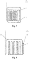
- FIGs. 3 and 4 show two common roll-folding modes for airbags in the prior art: a roll-folding manner (as shown in FIG. 3 ) and an N-fold manner (as shown in FIG. 4).
- FIG. 3 shows a schematic side view of an airbag folded in a roll-folding manner.
- An airbag assembly formed in such roll-folding mode easily maintains its external shape. Therefore, an airbag assembly can maintain its shape without additionally providing enclosures such as a seal cover when mounted to a vehicle.
- FIG. 4 shows that a cross section of an airbag folded in an N-fold manner is relatively flat; a small space is occupied in the vehicle; but a seal cover 4 is required to maintain the size.
- the seal cover 4 usually needs to enclose the airbag substantially over the entire extended length of the airbag. Because of the requirement for the seal covers, reducing cost becomes difficult.
- the airbag folded in current manners airbag folding occupies a large space in the vehicle and has a high mounting and fixation cost.
- the present invention provides an airbag, comprising a deployed state and a collapsed state, the airbag being capable of providing protection for occupants between the occupants and the inside of a vehicle when the airbag is inflated and expanded to be in the deployed state, and being capable of being accommodated in a predetermined space in the vehicle when in the collapsed state; the airbag comprising at least a first end and a second end, the first end being a free end of the airbag, and the second end being used for fixing the airbag to a mounting position; and the airbag comprising a folding portion and a rolling portion when in the collapsed state, wherein the folding portion is formed by folding one part of the airbag in an "N" shape; the rolling portion surrounds a periphery of the folding portion, so that the folding portion is completely surrounded by an inner side of the rolling portion; and the first end is also positioned at the inner side of the rolling portion.
- the rolling portion extends from the folding portion and integrally and continuously surrounds the periphery of the folding portion.
- the rolling portion is branched to comprise a first rolling sub-portion and a second rolling sub-portion; the first rolling sub-portion extends from the folding portion and surrounds at least one part of the periphery of the folding portion; and the second rolling sub-portion is branched from the first rolling sub-portion and surrounds at least one part of the periphery of the folding portion.
- an extending direction of the first rolling sub-portion surrounding around at least one part of the periphery of the folding portion is opposite to an extending direction of the second rolling sub-portion surrounding around at least one part of the folding portion.
- the rolling portion surrounds the periphery of the folding portion for only about one turn.
- the folding portion comprises the first end.
- the folding portion comprises the first end.
- the present invention further provides an airbag assembly, comprising: a gas generator; and the airbag according to the present invention.
- the airbag assembly further comprises a mounting device for fixing the airbag to a corresponding mounting position, the mounting device being fixed to the second end of the airbag.
- the mounting device is configured to surround a buckle of the airbag; and one part of the buckle is fixed to the second end of the airbag assembly.
- the airbag provided by the present invention has the advantages of needing only to take a small space of a vehicle and a low mounting and fixing cost.
- 1 curtain airbag
- 2 inner roof
- 3 vehicle side structure
- 4 seal cover
- 10, 20, 30, 40, 50, 100 airbag
- 12 second end
- 13, 23, 33, 43, 53 folding portion
- 14, 24, 34 rolling portion
- 142, 242, 442 second rolling sub-portion
- 240 branching positions
- 300 buckle.
- spatially related terms such as “upper”, “lower”, “left”, and “right” are used to describe a relative positional relationship between an element and another element shown in the drawings. Therefore, spatially related terms can be applied to directions that are different from those shown in the drawings in actual application. Obviously, although all of these spatially related terms refer to the directions shown in the drawings for ease of explanation, those skilled in the art could understand that directions different from those shown in the drawings may be used.
- the same or similar reference numerals denote the same or similar structures in the airbag.
- FIG. 5 shows a schematic side sectional view of an airbag 10 according to Embodiment 1 of the present invention.
- the airbag 10 has a first end 11 and a second end 12. Either the first end 11 or the second end 12 is used as a free end. The other one is used to fix the airbag 10 to a mounting position of a vehicle.
- the first end 11 is a free end of the airbag 10; and the second end 12 is used to fix the airbag 10 to a predetermined mounting position in the vehicle.
- the mounting position of the airbag 10 in the vehicle shown in FIG. 7 can refer to a mounting position of a curtain airbag 1 shown in FIGS. 1 and 2 . That is, the airbag 10 is positioned in a space under a vehicle side structure (e.g., a side door) and an inner roof.
- the airbag 10 shown in FIG. 5 is in a collapsed state and has a folding portion 13 and a rolling portion 14.
- the folding portion 13 is formed by folding one part of the airbag 10 in an "N" shape.
- the rolling portion 14 extends from the folding portion 13.
- the rolling portion 14 integrally and continuously surrounds a periphery of the folding portion 13.
- the rolling portion 14 surrounds the periphery of the folding portion 13 for about one turn, so that the folding portion 13 is completely surrounded by an inner side of the rolling portion 14; and the first end 11 is also positioned at the inner side of the rolling portion 14.
- the rolling portion 14 of the airbag 10 since the rolling portion 14 of the airbag 10 according to this embodiment of the present invention completely surrounds the folding portion 13, the shape of the airbag 10 can be maintained using the rolling portion 14 which serves as one part of the airbag 10. Therefore, the volume may be reduced by improving the compacting procedure of the "N" shape folding; and a seal cover is not needed for the airbag 10 to sufficiently maintain the shape thereof when the airbag is in the collapsed state. In this way, the cost for mounting and fixing the airbag 10 is greatly reduced.
- the cross section of the airbag 10 having the folding portion 13 may be configured to be flat to optimize the occupied space.
- the airbag 10 When it is desired to inflate and deploy the airbag 10, for example, in the event of a vehicle accident, the airbag 10 is inflated so as to expand and be deployed downward against a vehicle side structure 3; and the first end 11 is expanded to form a free end to provide protection for occupants in an occupant protection area.
- one part of the airbag may be folded in an "N" shape from the first end 11 to form the folding portion 13.
- the remaining part rolls around the folding portion 13 to form the rolling portion 14, so that the folding portion is completely surrounded by the inner side of the rolling portion 14. Accordingly, the first end is also positioned at the inner side of the rolling portion 14.
- FIG. 6 shows a side sectional view of an airbag 20 according to Embodiment 2 of the present invention.
- Embodiment 2 has substantially the same technical solution as Embodiment 1.
- a major difference is that a rolling portion 24 of the airbag 20 is branched into a first rolling sub-portion 241 and a second rolling sub-portion 242.
- the first rolling sub-portion 241 extends from a folding portion 23 and surrounds at least one part of a periphery of the folding portion 23.
- the second rolling sub-portion 242 is branched from the first rolling sub-portion 241 and surrounds at least one part of the periphery of the folding portion 23.
- first rolling sub-portion 241 and the second rolling sub-portion 242 are branched are taken as origins, then an extending direction of the first rolling sub-portion 241 surrounding at least one part of the periphery of the folding portion 23 is opposite to an extending direction of the second rolling sub-portion 242 surrounding at least one part of the folding portion 23. Together the first rolling sub-portion 241 and the second rolling sub-portion 242 completely surround the folding portion 23.
- the first end 21 is also positioned at the inner side of the rolling portion 24.
- the rolling portion 24 of the airbag 20 comprises the first rolling sub-portion 241 and the second rolling sub-portion 242. Since together the first rolling sub-portion 241 and the second rolling sub-portion 242 completely surround the folding portion 23, the airbag 20 no longer needs a seal cover to maintain the shape in the collapsed state. In this way, the cost for mounting and fixing the airbag is reduced. At the same time, the cross section of the airbag 20 having the folding portion 23 is flat, so the space occupied in the vehicle is small.
- the second rolling sub-portion 242 may be formed integrally with the first rolling sub-portion 241, or may also be mounted, as a separate component, to the first rolling sub-portion 241 by sewing, bonding, and other manners.
- the collapsed state of the airbag may be better maintained by mounting one end of the second rolling sub-portion 242 to a position of the first rolling sub-portion 241 proximate to the second end of the air bag and then rolling the second rolling sub-portion 242 around the folding portion.
- the expansion and deployment process of the airbag 20 according to this embodiment of the present invention is similar to that in Embodiment 1 and will not be described in detail herein.
- one part of the airbag may be folded in an "N" shape from the first end 21 to form the folding portion 23.
- the remaining part rolls around the folding portion 23 to, for example, a branching point 240, to form the first rolling sub-portion 241.
- Branched portions continue to roll from the branching point 240 to form the second rolling sub-portion 242.
- the folding portion is completely surrounded by the inner side of the rolling portion 24.
- the first end 23 is also positioned at the inner side of the rolling portion 24.
- the rolling portion 14 surrounds the periphery of the folding portion 13 for only about one turn.
- the rolling portion 14 may also surround the periphery of the folding portion 13 for more than one turn or even multiple turns.
- the rolling portion 14 surrounds the periphery of the folding portion 13 for about two turns. With a large number of turns, the shape of the airbag in the folded collapsed state can be better maintained, but the deployment speed of the airbag may be adversely affected.
- an extending direction of the first rolling sub-portion 241 surrounding at least one part of the periphery of the folding portion 23 is opposite to an extending direction of the second rolling sub-portion 242 surrounding at least one part of the periphery of the folding portion 23.
- the present invention is not limited to the implementation shown in FIG. 8 .
- the present invention may further comprise an implementation as shown in FIG. 8 . That is, the extending direction of the first rolling sub-portion 441 surrounding at least one part of the periphery of the folding portion 43 is the same as the extending direction of the second rolling sub-portion 442 surrounding at least one part of the periphery of the folding portion 43.
- the folding portion includes the first end as the free end. That is, at the time of manufacturing, the folding portion may be formed by firstly folding the free end in an "N" shape.
- the present invention may also comprise an implementation as shown in FIG. 9 . That is, the first end 51 is not comprised in the folding portion 53 and thus is not one part of the folding portion 53.
- folding may be performed from a position, which is at a certain distance from the free end 51, to form the folding portion 53.
- the free end 51 as one part of a starting point may also be formed to roll around one part or even the periphery of the folding portion. It will also be understood that in this case, if the length from the free end 51 to the folding portion 53 is sufficiently long, it is also possible to form one part thereof as another folding portion. In all of these cases, it is possible to achieve the object of the present invention by forming the outermost rolling portion to surround the periphery of the folding portion and allowing the first end to be positioned inside the rolling portion.
- the present invention further provides an airbag assembly.
- the airbag assembly comprises a gas generator and the airbag according to the foregoing embodiments.
- the gas generator is used to inflate the airbag when detonated, so as to inflate and deploy the airbag.
- the airbag assembly may further comprise a buckle 300 for fixing the airbag to a corresponding mounting position.
- a schematic diagram of the vicinity of the buckle 300 is shown.
- the airbag 100 is not fully shown, but only one section thereof near the buckle 300 is shown.
- One part of the buckle 300 is fixed to the second end of the airbag (not shown in the drawing) and surrounds the airbag 100.
- Another part of the buckle 300 protrudes through an opening of an end of the buckle to surround the outer periphery of the airbag.
- the protruded part can be used for fixing the airbag to the corresponding mounting position.
- the buckle 300 can maintain the shape of the airbag 100 and can easily mount the airbag assembly.
- the airbag according to the present invention itself can maintain a smooth integrated shape, it is possible to eliminate the need for a seal cover. Moreover, it is possible to use a simple device such as a buckle to maintain the shape and perform the mounting.
- the mounting device of the airbag assembly is not limited to the above-described buckle.
- Those skilled in the art could use any mounting device that can fix the airbag to a predetermined mounting position of the vehicle according to specific situations.
- the airbag can be fixed to the predetermined mounting position of the vehicle by means of concave and hooked members and the like and/or in a way of riveting, bonding, snapping and the like depending on specific application scenarios.
Abstract
Description
- The present invention relates to a safety device for vehicles, and in particular, to an airbag and an airbag assembly.
- Airbags used in vehicles are important devices frequently used in emergency situations to protect occupants within vehicles from injured. As one type of airbags, a curtain airbag is typically mounted at an upper portion of a side door and positioned at an edge of a vehicle structure under the inner roof. Moreover, the curtain airbag is inflated when a vehicle is impacted, so that it expands and is deployed in an inflated state against a vehicle side structure, such as a side window, inside the vehicle. In this way, the occupants can be prevented from serious injuries caused by directly hitting the inside structures of the vehicle or being thrown out of a vehicle window. An example of such curtain airbag is shown in
FIGs. 1 and 2 . Specifically,FIG. 1 shows a state in which a curtain airbag 1 in a collapsed state is roll-folded and stored in a space under a vehicle side structure 3 (e.g., a side door) and aninner roof 2 when viewed in the length direction of a vehicle (i.e., a left-and-right direction ofFIG. 1 is a width direction of the vehicle).FIG. 2 shows that the curtain airbag 1 in a deployed state in which it is inflated and expanded in the length direction of the vehicle (i.e., a left-and-right direction ofFIG. 2 ), and the airbag is deployed downward along thevehicle side structure 3, so as to provide protection for occupants in the occupant protection area. - Because a mounting space of an airbag is very limited, the airbag is typically mounted in a rolled state or a folded and collapsed state in a particular space of a vehicle.
FIGs. 3 and 4 show two common roll-folding modes for airbags in the prior art: a roll-folding manner (as shown inFIG. 3 ) and an N-fold manner (as shown inFIG. 4). FIG. 3 shows a schematic side view of an airbag folded in a roll-folding manner. An airbag assembly formed in such roll-folding mode easily maintains its external shape. Therefore, an airbag assembly can maintain its shape without additionally providing enclosures such as a seal cover when mounted to a vehicle. However, the diameter of such airbag assembly is relatively large and thus often is unable to meet the limited mounting space requirement in the vehicle.FIG. 4 shows that a cross section of an airbag folded in an N-fold manner is relatively flat; a small space is occupied in the vehicle; but aseal cover 4 is required to maintain the size. However, because the outer shape of the airbag folded in the N-fold manner is not flat, theseal cover 4 usually needs to enclose the airbag substantially over the entire extended length of the airbag. Because of the requirement for the seal covers, reducing cost becomes difficult. - Therefore, the airbag folded in current manners airbag folding occupies a large space in the vehicle and has a high mounting and fixation cost.
- In order to solve the above-mentioned problems, the present invention provides an airbag, comprising a deployed state and a collapsed state, the airbag being capable of providing protection for occupants between the occupants and the inside of a vehicle when the airbag is inflated and expanded to be in the deployed state, and being capable of being accommodated in a predetermined space in the vehicle when in the collapsed state; the airbag comprising at least a first end and a second end, the first end being a free end of the airbag, and the second end being used for fixing the airbag to a mounting position; and the airbag comprising a folding portion and a rolling portion when in the collapsed state, wherein the folding portion is formed by folding one part of the airbag in an "N" shape; the rolling portion surrounds a periphery of the folding portion, so that the folding portion is completely surrounded by an inner side of the rolling portion; and the first end is also positioned at the inner side of the rolling portion.
- According to one embodiment of the present invention, the rolling portion extends from the folding portion and integrally and continuously surrounds the periphery of the folding portion.
- According to one embodiment of the present invention, the rolling portion is branched to comprise a first rolling sub-portion and a second rolling sub-portion; the first rolling sub-portion extends from the folding portion and surrounds at least one part of the periphery of the folding portion; and the second rolling sub-portion is branched from the first rolling sub-portion and surrounds at least one part of the periphery of the folding portion.
- Herein, in a case where positions of the first rolling sub-portion and the second rolling sub-portion are branched are used as origins, an extending direction of the first rolling sub-portion surrounding around at least one part of the periphery of the folding portion is opposite to an extending direction of the second rolling sub-portion surrounding around at least one part of the folding portion.
- Preferably, the rolling portion surrounds the periphery of the folding portion for only about one turn.
- Preferably, the folding portion comprises the first end.
- Preferably, the folding portion comprises the first end.
- The present invention further provides an airbag assembly, comprising: a gas generator; and the airbag according to the present invention.
- According to one embodiment of the present invention, the airbag assembly further comprises a mounting device for fixing the airbag to a corresponding mounting position, the mounting device being fixed to the second end of the airbag.
- Preferably, the mounting device is configured to surround a buckle of the airbag; and one part of the buckle is fixed to the second end of the airbag assembly.
- The airbag provided by the present invention has the advantages of needing only to take a small space of a vehicle and a low mounting and fixing cost.
- The present invention will be described in detail below with reference to the accompanying drawings:
-
FIG. 1 shows a schematic view of a mounting position of an airbag 1 in a vehicle when viewed from a length direction of the vehicle according to the prior art, the airbag 1 being in a collapsed state; -
FIG. 2 shows a schematic view of a position of the airbag 1 in the vehicle when viewed from a width direction of the vehicle according to the prior art, the airbag being in a deployed state; -
FIG. 3 shows a schematic side sectional view of a roll-folding manner of the airbag 1 according to the prior art; -
FIG. 4 shows a schematic side sectional view of an N-fold manner of the airbag 1 according to the prior art; -
FIG. 5 shows a side sectional view of anairbag 10 according to embodiment 1 of the present invention; -
FIG. 6 shows a side sectional view of anairbag 20 according toembodiment 2 of the present invention; -
FIG. 7 shows a folding manner of the airbag 1 according to another embodiment of the present invention; -
FIG. 8 shows a folding manner of the airbag 1 according to another embodiment of the present invention; -
FIG. 9 shows a folding manner of the airbag 1 according to another embodiment of the present invention; -
FIG. 10 shows a schematic view of a buckle for fixing the airbag to a mounting position according to the present invention. - Reference numerals of the drawings, 1: curtain airbag; 2: inner roof; 3: vehicle side structure; 4: seal cover; 10, 20, 30, 40, 50, 100: airbag; 11, 21, 51: first end; 12: second end; 13, 23, 33, 43, 53: folding portion; 14, 24, 34: rolling portion; 141, 241, 441: first rolling sub-portion; 142, 242, 442: second rolling sub-portion; 240: branching positions; 300: buckle.
- Specific implementations of an airbag according to the present invention will be described below with reference to the accompanying drawings. The detailed description and drawings below are used for exemplarily illustrating the principle of the present invention. The present invention is not limited to the described preferred embodiments. The protection scope of the present invention is defined by the claims.
- In addition, spatially related terms (such as "upper", "lower", "left", and "right") are used to describe a relative positional relationship between an element and another element shown in the drawings. Therefore, spatially related terms can be applied to directions that are different from those shown in the drawings in actual application. Obviously, although all of these spatially related terms refer to the directions shown in the drawings for ease of explanation, those skilled in the art could understand that directions different from those shown in the drawings may be used. The same or similar reference numerals denote the same or similar structures in the airbag.
- The airbag according to the embodiments of the present invention will be described below with reference to the accompanying drawings.
-
FIG. 5 shows a schematic side sectional view of anairbag 10 according to Embodiment 1 of the present invention. As shown inFIG. 5 , theairbag 10 has afirst end 11 and asecond end 12. Either thefirst end 11 or thesecond end 12 is used as a free end. The other one is used to fix theairbag 10 to a mounting position of a vehicle. For example, in this embodiment, thefirst end 11 is a free end of theairbag 10; and thesecond end 12 is used to fix theairbag 10 to a predetermined mounting position in the vehicle. The mounting position of theairbag 10 in the vehicle shown inFIG. 7 can refer to a mounting position of a curtain airbag 1 shown inFIGS. 1 and 2 . That is, theairbag 10 is positioned in a space under a vehicle side structure (e.g., a side door) and an inner roof. - The
airbag 10 shown inFIG. 5 is in a collapsed state and has a foldingportion 13 and arolling portion 14. The foldingportion 13 is formed by folding one part of theairbag 10 in an "N" shape. The rollingportion 14 extends from the foldingportion 13. Moreover, the rollingportion 14 integrally and continuously surrounds a periphery of thefolding portion 13. In Embodiment 1, the rollingportion 14 surrounds the periphery of thefolding portion 13 for about one turn, so that thefolding portion 13 is completely surrounded by an inner side of the rollingportion 14; and thefirst end 11 is also positioned at the inner side of the rollingportion 14. - Since the rolling
portion 14 of theairbag 10 according to this embodiment of the present invention completely surrounds thefolding portion 13, the shape of theairbag 10 can be maintained using the rollingportion 14 which serves as one part of theairbag 10. Therefore, the volume may be reduced by improving the compacting procedure of the "N" shape folding; and a seal cover is not needed for theairbag 10 to sufficiently maintain the shape thereof when the airbag is in the collapsed state. In this way, the cost for mounting and fixing theairbag 10 is greatly reduced. At the same time, the cross section of theairbag 10 having the foldingportion 13 may be configured to be flat to optimize the occupied space. - When it is desired to inflate and deploy the
airbag 10, for example, in the event of a vehicle accident, theairbag 10 is inflated so as to expand and be deployed downward against avehicle side structure 3; and thefirst end 11 is expanded to form a free end to provide protection for occupants in an occupant protection area. - In addition, as an example, when the
airbag 10 shown in Embodiment 1 is manufactured, one part of the airbag may be folded in an "N" shape from thefirst end 11 to form thefolding portion 13. Next, the remaining part rolls around the foldingportion 13 to form the rollingportion 14, so that the folding portion is completely surrounded by the inner side of the rollingportion 14. Accordingly, the first end is also positioned at the inner side of the rollingportion 14. -
FIG. 6 shows a side sectional view of anairbag 20 according toEmbodiment 2 of the present invention.Embodiment 2 has substantially the same technical solution as Embodiment 1. A major difference is that a rollingportion 24 of theairbag 20 is branched into a first rollingsub-portion 241 and a second rollingsub-portion 242. The first rollingsub-portion 241 extends from afolding portion 23 and surrounds at least one part of a periphery of thefolding portion 23. Thesecond rolling sub-portion 242 is branched from the first rollingsub-portion 241 and surrounds at least one part of the periphery of thefolding portion 23. - In the embodiment shown in
FIG. 6 , ifpositions 240 where the first rollingsub-portion 241 and the second rollingsub-portion 242 are branched are taken as origins, then an extending direction of the first rollingsub-portion 241 surrounding at least one part of the periphery of thefolding portion 23 is opposite to an extending direction of the second rollingsub-portion 242 surrounding at least one part of thefolding portion 23. Together the first rollingsub-portion 241 and the second rollingsub-portion 242 completely surround thefolding portion 23. In addition, thefirst end 21 is also positioned at the inner side of the rollingportion 24. - The rolling
portion 24 of theairbag 20 according to this embodiment of the present invention comprises the first rollingsub-portion 241 and the second rollingsub-portion 242. Since together the first rollingsub-portion 241 and the second rollingsub-portion 242 completely surround thefolding portion 23, theairbag 20 no longer needs a seal cover to maintain the shape in the collapsed state. In this way, the cost for mounting and fixing the airbag is reduced. At the same time, the cross section of theairbag 20 having the foldingportion 23 is flat, so the space occupied in the vehicle is small. - In
Embodiment 2 of the present invention, the second rollingsub-portion 242 may be formed integrally with the first rollingsub-portion 241, or may also be mounted, as a separate component, to the first rollingsub-portion 241 by sewing, bonding, and other manners. For example, the collapsed state of the airbag may be better maintained by mounting one end of the second rollingsub-portion 242 to a position of the first rollingsub-portion 241 proximate to the second end of the air bag and then rolling the second rollingsub-portion 242 around the folding portion. - The expansion and deployment process of the
airbag 20 according to this embodiment of the present invention is similar to that in Embodiment 1 and will not be described in detail herein. - In addition, as an example, when the
airbag 20 shown inEmbodiment 2 is manufactured, one part of the airbag may be folded in an "N" shape from thefirst end 21 to form thefolding portion 23. Next, the remaining part rolls around the foldingportion 23 to, for example, a branchingpoint 240, to form the first rollingsub-portion 241. Branched portions continue to roll from the branchingpoint 240 to form the second rollingsub-portion 242. In this way, the folding portion is completely surrounded by the inner side of the rollingportion 24. Moreover, thefirst end 23 is also positioned at the inner side of the rollingportion 24. - Although some embodiments of the airbag according to the present invention are described previously, the present invention is not limited thereto. Other implementations are also possible.
- As Embodiment 1 of the present invention, as shown in
FIG. 5 , the rollingportion 14 surrounds the periphery of thefolding portion 13 for only about one turn. However, those skilled in the art could understand that the rollingportion 14 may also surround the periphery of thefolding portion 13 for more than one turn or even multiple turns. For example, as shown inFIG. 7 , the rollingportion 14 surrounds the periphery of thefolding portion 13 for about two turns. With a large number of turns, the shape of the airbag in the folded collapsed state can be better maintained, but the deployment speed of the airbag may be adversely affected. - As
Embodiment 2 of the present invention, as shown inFIG. 6 , an extending direction of the first rollingsub-portion 241 surrounding at least one part of the periphery of thefolding portion 23 is opposite to an extending direction of the second rollingsub-portion 242 surrounding at least one part of the periphery of thefolding portion 23. However, those skilled in the art could understand that the present invention is not limited to the implementation shown inFIG. 8 . For example, the present invention may further comprise an implementation as shown inFIG. 8 . That is, the extending direction of the first rollingsub-portion 441 surrounding at least one part of the periphery of thefolding portion 43 is the same as the extending direction of the second rollingsub-portion 442 surrounding at least one part of the periphery of thefolding portion 43. - In the foregoing embodiments of the present invention, the folding portion includes the first end as the free end. That is, at the time of manufacturing, the folding portion may be formed by firstly folding the free end in an "N" shape. However, those skilled in the art could understand that the present invention is not limited thereto. For example, the present invention may also comprise an implementation as shown in
FIG. 9 . That is, thefirst end 51 is not comprised in thefolding portion 53 and thus is not one part of thefolding portion 53. In this embodiment, for example, at the time of manufacturing, folding may be performed from a position, which is at a certain distance from thefree end 51, to form thefolding portion 53. In addition, thefree end 51 as one part of a starting point may also be formed to roll around one part or even the periphery of the folding portion. It will also be understood that in this case, if the length from thefree end 51 to thefolding portion 53 is sufficiently long, it is also possible to form one part thereof as another folding portion. In all of these cases, it is possible to achieve the object of the present invention by forming the outermost rolling portion to surround the periphery of the folding portion and allowing the first end to be positioned inside the rolling portion. - In addition to the airbag described above, the present invention further provides an airbag assembly. The airbag assembly comprises a gas generator and the airbag according to the foregoing embodiments. The gas generator is used to inflate the airbag when detonated, so as to inflate and deploy the airbag.
- More specifically, the airbag assembly may further comprise a
buckle 300 for fixing the airbag to a corresponding mounting position. As shown inFIG. 10 , a schematic diagram of the vicinity of thebuckle 300 is shown. InFIG. 10 , theairbag 100 is not fully shown, but only one section thereof near thebuckle 300 is shown. One part of thebuckle 300 is fixed to the second end of the airbag (not shown in the drawing) and surrounds theairbag 100. Another part of thebuckle 300 protrudes through an opening of an end of the buckle to surround the outer periphery of the airbag. The protruded part can be used for fixing the airbag to the corresponding mounting position. Thus, thebuckle 300 can maintain the shape of theairbag 100 and can easily mount the airbag assembly. - Since the airbag according to the present invention itself can maintain a smooth integrated shape, it is possible to eliminate the need for a seal cover. Moreover, it is possible to use a simple device such as a buckle to maintain the shape and perform the mounting.
- Those skilled in the art could understand that the mounting device of the airbag assembly is not limited to the above-described buckle. Those skilled in the art could use any mounting device that can fix the airbag to a predetermined mounting position of the vehicle according to specific situations. For example, the airbag can be fixed to the predetermined mounting position of the vehicle by means of concave and hooked members and the like and/or in a way of riveting, bonding, snapping and the like depending on specific application scenarios.
- As described above, although the exemplary embodiments of the present invention have been described with reference to the accompanying drawings in the description, the present invention is not limited to the above-mentioned specific implementations. The protection scope of the present invention should be defined by the claims and their equivalent meanings.
Claims (10)
- An airbag, comprising a deployed state and a collapsed state, the airbag being capable of providing protection for occupants between the occupants and the inside of a vehicle when the airbag is inflated and expanded to be in the deployed state, and being capable of being accommodated in a predetermined space in the vehicle when in the collapsed state;
the airbag comprising at least a first end and a second end, the first end being a free end of the airbag, and the second end being used for fixing the airbag to a mounting position; and
the airbag comprising a folding portion and a rolling portion when in the collapsed state, wherein
the folding portion is formed by folding one part of the airbag in an "N" shape; the rolling portion surrounds a periphery of the folding portion, so that the folding portion is completely surrounded by an inner side of the rolling portion; and the first end is also positioned at the inner side of the rolling portion. - The airbag according to claim 1, wherein the rolling portion extends from the folding portion and integrally and continuously surrounds the periphery of the folding portion.
- The airbag according to claim 1, wherein the rolling portion is branched to comprise a first rolling sub-portion and a second rolling sub-portion; the first rolling sub-portion extends from the folding portion and surrounds at least one part of the periphery of the folding portion; and the second rolling sub-portion is branched from the first rolling sub-portion and surrounds at least one part of the periphery of the folding portion.
- The airbag according to claim 3, wherein in a case where positions of the first rolling sub-portion and the second rolling sub-portion are branched are used as origins, an extending direction of the first rolling sub-portion surrounding at least one part of the periphery of the folding portion is opposite to an extending direction of the second rolling sub-portion surrounding at least one part of the folding portion.
- The airbag according to any one of claims 1 to 4, wherein the rolling portion surrounds the periphery of the folding portion for only about one turn.
- The airbag according to any one of claims 1 to 4, wherein the folding portion comprises the first end.
- The airbag according to claim 5, wherein the folding portion comprises the first end.
- An airbag assembly, comprising:a gas generator; andthe airbag according to any one of claims 1 to 7.
- The airbag assembly according to claim 8, further comprising:
a mounting device for fixing the airbag to a corresponding mounting position, the mounting device being fixed to the second end of the airbag. - The airbag assembly according to claim 9, wherein the mounting device is configured to surround a buckle of the airbag; and one part of the buckle is fixed to the second end of the airbag assembly.
Applications Claiming Priority (2)
| Application Number | Priority Date | Filing Date | Title |
|---|---|---|---|
| CN201610188115.7A CN107235028B (en) | 2016-03-29 | 2016-03-29 | Airbag and airbag module |
| PCT/CN2016/113482 WO2017166882A1 (en) | 2016-03-29 | 2016-12-30 | Airbag and airbag assembly |
Publications (3)
| Publication Number | Publication Date |
|---|---|
| EP3412517A1 true EP3412517A1 (en) | 2018-12-12 |
| EP3412517A4 EP3412517A4 (en) | 2019-07-03 |
| EP3412517B1 EP3412517B1 (en) | 2020-10-28 |
Family
ID=59962557
Family Applications (1)
| Application Number | Title | Priority Date | Filing Date |
|---|---|---|---|
| EP16896650.5A Active EP3412517B1 (en) | 2016-03-29 | 2016-12-30 | Airbag and airbag assembly |
Country Status (6)
| Country | Link |
|---|---|
| US (1) | US10994693B2 (en) |
| EP (1) | EP3412517B1 (en) |
| JP (1) | JP6816161B2 (en) |
| KR (1) | KR102125036B1 (en) |
| CN (1) | CN107235028B (en) |
| WO (1) | WO2017166882A1 (en) |
Families Citing this family (5)
| Publication number | Priority date | Publication date | Assignee | Title |
|---|---|---|---|---|
| CN110745097A (en) * | 2018-07-24 | 2020-02-04 | 奥托立夫开发公司 | Airbag, airbag module and folding method for an airbag |
| US10906497B2 (en) * | 2018-10-18 | 2021-02-02 | Trw Vehicle Safety Systems Inc. | Airbag with deployment controlling flap |
| US11433845B2 (en) * | 2019-11-08 | 2022-09-06 | Autoliv Asp, Inc. | Airbag assembly with reduced package size and related method |
| CN113386700B (en) * | 2020-03-13 | 2023-01-31 | 奥托立夫开发公司 | Method for manufacturing airbag device and airbag device |
| CN117080673B (en) * | 2023-10-17 | 2024-01-26 | 厦门海辰储能科技股份有限公司 | Battery module and power utilization device |
Family Cites Families (25)
| Publication number | Priority date | Publication date | Assignee | Title |
|---|---|---|---|---|
| JPH07149196A (en) * | 1993-11-30 | 1995-06-13 | Toyoda Gosei Co Ltd | Air bag device for front passenger seat |
| JPH11291850A (en) | 1998-04-08 | 1999-10-26 | Takata Kk | Front passenger seat air bag and method for folding the same |
| JP3887167B2 (en) * | 2000-12-13 | 2007-02-28 | 本田技研工業株式会社 | Airbag folding method in side impact airbag device |
| JP4336072B2 (en) * | 2001-11-26 | 2009-09-30 | 日本プラスト株式会社 | Airbag |
| JP2003327183A (en) * | 2002-05-15 | 2003-11-19 | Takata Corp | Air bag device for motorcycle, manufacturing method of air bag device for motorcycle and motorcycle with air bag device |
| DE10237401A1 (en) * | 2002-08-09 | 2004-03-11 | Takata-Petri (Ulm) Gmbh | Occupant protection device for a vehicle |
| GB2394921A (en) | 2002-11-07 | 2004-05-12 | Autoliv Dev | A vehicle curtain type air bag rolled up when not in use |
| US20050070414A1 (en) * | 2003-09-11 | 2005-03-31 | Schneider David W. | Cushion fold patterns for overhead airbags |
| GB2407540A (en) | 2003-10-31 | 2005-05-04 | Autotoliv Dev Ab | Rolled inflatable airbag curtain |
| US7243940B2 (en) * | 2003-11-20 | 2007-07-17 | Delphi Technologies, Inc. | Side airbag and method of folding |
| DE102005011676B4 (en) | 2005-03-11 | 2012-04-19 | Autoliv Development Ab | Curtain airbag and motor vehicle |
| JP2007091177A (en) * | 2005-09-30 | 2007-04-12 | Nippon Plast Co Ltd | Air bag for vehicle and air bag device mounted with it |
| DE102006061968A1 (en) | 2006-12-21 | 2008-07-03 | Autoliv Development Ab | Curtain airbag |
| JP5195400B2 (en) * | 2008-12-24 | 2013-05-08 | タカタ株式会社 | Air bag and air bag device |
| US8240701B2 (en) * | 2009-09-08 | 2012-08-14 | Autoliv Asp, Inc. | Mounting assemblies with wrappers for inflatable curtain airbags |
| JP5440232B2 (en) * | 2010-02-12 | 2014-03-12 | トヨタ自動車株式会社 | Curtain airbag device for vehicle |
| KR101743650B1 (en) * | 2011-09-20 | 2017-06-05 | 현대모비스 주식회사 | A side airbag cushion |
| JP5959379B2 (en) * | 2012-09-13 | 2016-08-02 | タカタ株式会社 | Air bag, air bag device, and air bag mounting structure |
| WO2014132810A1 (en) | 2013-02-28 | 2014-09-04 | オートリブ ディベロップメント エービー | Curtain airbag |
| CN105209301B (en) * | 2013-03-13 | 2017-09-01 | 天合汽车安全系统股份有限公司 | Inflatable gas curtain and the method for being arranged in inflatable gas curtain in storage state |
| CN105473387B (en) * | 2013-08-23 | 2017-08-04 | 本田技研工业株式会社 | Air bag device |
| US9975519B2 (en) * | 2014-04-30 | 2018-05-22 | Autoliv Development Ab | Side airbag apparatus for vehicle |
| KR102203274B1 (en) * | 2014-08-27 | 2021-01-18 | 현대모비스 주식회사 | Curtain Airbag Of Vehicle |
| CN108463378B (en) * | 2016-01-15 | 2020-09-04 | 奥托立夫开发公司 | Curtain airbag device and mounting structure for vehicle |
| JP2020100353A (en) * | 2018-12-25 | 2020-07-02 | Joyson Safety Systems Japan株式会社 | Airbag device |
-
2016
- 2016-03-29 CN CN201610188115.7A patent/CN107235028B/en active Active
- 2016-12-30 JP JP2018546420A patent/JP6816161B2/en active Active
- 2016-12-30 KR KR1020187022744A patent/KR102125036B1/en active IP Right Grant
- 2016-12-30 EP EP16896650.5A patent/EP3412517B1/en active Active
- 2016-12-30 US US16/089,437 patent/US10994693B2/en active Active
- 2016-12-30 WO PCT/CN2016/113482 patent/WO2017166882A1/en active Application Filing
Also Published As
| Publication number | Publication date |
|---|---|
| KR20180100649A (en) | 2018-09-11 |
| EP3412517B1 (en) | 2020-10-28 |
| EP3412517A4 (en) | 2019-07-03 |
| US20200298788A1 (en) | 2020-09-24 |
| CN107235028B (en) | 2021-10-01 |
| US10994693B2 (en) | 2021-05-04 |
| CN107235028A (en) | 2017-10-10 |
| KR102125036B1 (en) | 2020-06-19 |
| WO2017166882A1 (en) | 2017-10-05 |
| JP6816161B2 (en) | 2021-01-20 |
| JP2019507704A (en) | 2019-03-22 |
Similar Documents
| Publication | Publication Date | Title |
|---|---|---|
| EP3412517B1 (en) | Airbag and airbag assembly | |
| JP6085470B2 (en) | Airbag device | |
| US11377065B2 (en) | Safety airbag, safety airbag assembly and method for folding safety airbag | |
| EP2666677B1 (en) | Cover and air bag device | |
| US20060138750A1 (en) | Mounting structure of curtain airbag | |
| US8740247B1 (en) | Airbag assembly | |
| KR101460725B1 (en) | An airbag of vehicle | |
| US9266492B2 (en) | Curtain airbag module | |
| JP5427220B2 (en) | Curtain airbag | |
| JP2018008633A (en) | Side curtain airbag device | |
| US20220340099A1 (en) | Airbag module | |
| JP2006335173A (en) | Collided object protective device | |
| EP4067175A1 (en) | Airbag module | |
| WO2013146076A1 (en) | Head protection air bag system | |
| US8925961B2 (en) | Curtain airbag device | |
| KR101360437B1 (en) | Air bag cushion module for curtain air bag device | |
| WO2021169544A1 (en) | Airbag and folding method for airbag | |
| WO2012124548A1 (en) | Airbag device | |
| JP6768079B2 (en) | Curtain airbag device | |
| JP6017270B2 (en) | Airbag device | |
| WO2022057652A1 (en) | Airbag and arrangement for vehicle | |
| KR20050122344A (en) | A bracket structure for curtain airbag action | |
| JP2016011093A (en) | Air-bag module |
Legal Events
| Date | Code | Title | Description |
|---|---|---|---|
| STAA | Information on the status of an ep patent application or granted ep patent |
Free format text: STATUS: THE INTERNATIONAL PUBLICATION HAS BEEN MADE |
|
| PUAI | Public reference made under article 153(3) epc to a published international application that has entered the european phase |
Free format text: ORIGINAL CODE: 0009012 |
|
| STAA | Information on the status of an ep patent application or granted ep patent |
Free format text: STATUS: REQUEST FOR EXAMINATION WAS MADE |
|
| 17P | Request for examination filed |
Effective date: 20180903 |
|
| AK | Designated contracting states |
Kind code of ref document: A1 Designated state(s): AL AT BE BG CH CY CZ DE DK EE ES FI FR GB GR HR HU IE IS IT LI LT LU LV MC MK MT NL NO PL PT RO RS SE SI SK SM TR |
|
| AX | Request for extension of the european patent |
Extension state: BA ME |
|
| A4 | Supplementary search report drawn up and despatched |
Effective date: 20190603 |
|
| DAV | Request for validation of the european patent (deleted) | ||
| DAX | Request for extension of the european patent (deleted) | ||
| RIC1 | Information provided on ipc code assigned before grant |
Ipc: B60R 21/213 20110101ALI20190527BHEP Ipc: B60R 21/237 20060101AFI20190527BHEP |
|
| STAA | Information on the status of an ep patent application or granted ep patent |
Free format text: STATUS: EXAMINATION IS IN PROGRESS |
|
| 17Q | First examination report despatched |
Effective date: 20200228 |
|
| GRAP | Despatch of communication of intention to grant a patent |
Free format text: ORIGINAL CODE: EPIDOSNIGR1 |
|
| STAA | Information on the status of an ep patent application or granted ep patent |
Free format text: STATUS: GRANT OF PATENT IS INTENDED |
|
| INTG | Intention to grant announced |
Effective date: 20200619 |
|
| GRAS | Grant fee paid |
Free format text: ORIGINAL CODE: EPIDOSNIGR3 |
|
| GRAA | (expected) grant |
Free format text: ORIGINAL CODE: 0009210 |
|
| STAA | Information on the status of an ep patent application or granted ep patent |
Free format text: STATUS: THE PATENT HAS BEEN GRANTED |
|
| AK | Designated contracting states |
Kind code of ref document: B1 Designated state(s): AL AT BE BG CH CY CZ DE DK EE ES FI FR GB GR HR HU IE IS IT LI LT LU LV MC MK MT NL NO PL PT RO RS SE SI SK SM TR |
|
| REG | Reference to a national code |
Ref country code: GB Ref legal event code: FG4D |
|
| REG | Reference to a national code |
Ref country code: CH Ref legal event code: EP |
|
| REG | Reference to a national code |
Ref country code: AT Ref legal event code: REF Ref document number: 1327905 Country of ref document: AT Kind code of ref document: T Effective date: 20201115 |
|
| REG | Reference to a national code |
Ref country code: DE Ref legal event code: R096 Ref document number: 602016046930 Country of ref document: DE |
|
| REG | Reference to a national code |
Ref country code: IE Ref legal event code: FG4D |
|
| REG | Reference to a national code |
Ref country code: AT Ref legal event code: MK05 Ref document number: 1327905 Country of ref document: AT Kind code of ref document: T Effective date: 20201028 |
|
| REG | Reference to a national code |
Ref country code: NL Ref legal event code: MP Effective date: 20201028 |
|
| PG25 | Lapsed in a contracting state [announced via postgrant information from national office to epo] |
Ref country code: NO Free format text: LAPSE BECAUSE OF FAILURE TO SUBMIT A TRANSLATION OF THE DESCRIPTION OR TO PAY THE FEE WITHIN THE PRESCRIBED TIME-LIMIT Effective date: 20210128 Ref country code: PT Free format text: LAPSE BECAUSE OF FAILURE TO SUBMIT A TRANSLATION OF THE DESCRIPTION OR TO PAY THE FEE WITHIN THE PRESCRIBED TIME-LIMIT Effective date: 20210301 Ref country code: RS Free format text: LAPSE BECAUSE OF FAILURE TO SUBMIT A TRANSLATION OF THE DESCRIPTION OR TO PAY THE FEE WITHIN THE PRESCRIBED TIME-LIMIT Effective date: 20201028 Ref country code: FI Free format text: LAPSE BECAUSE OF FAILURE TO SUBMIT A TRANSLATION OF THE DESCRIPTION OR TO PAY THE FEE WITHIN THE PRESCRIBED TIME-LIMIT Effective date: 20201028 Ref country code: GR Free format text: LAPSE BECAUSE OF FAILURE TO SUBMIT A TRANSLATION OF THE DESCRIPTION OR TO PAY THE FEE WITHIN THE PRESCRIBED TIME-LIMIT Effective date: 20210129 |
|
| REG | Reference to a national code |
Ref country code: LT Ref legal event code: MG4D |
|
| PG25 | Lapsed in a contracting state [announced via postgrant information from national office to epo] |
Ref country code: AT Free format text: LAPSE BECAUSE OF FAILURE TO SUBMIT A TRANSLATION OF THE DESCRIPTION OR TO PAY THE FEE WITHIN THE PRESCRIBED TIME-LIMIT Effective date: 20201028 Ref country code: ES Free format text: LAPSE BECAUSE OF FAILURE TO SUBMIT A TRANSLATION OF THE DESCRIPTION OR TO PAY THE FEE WITHIN THE PRESCRIBED TIME-LIMIT Effective date: 20201028 Ref country code: IS Free format text: LAPSE BECAUSE OF FAILURE TO SUBMIT A TRANSLATION OF THE DESCRIPTION OR TO PAY THE FEE WITHIN THE PRESCRIBED TIME-LIMIT Effective date: 20210228 Ref country code: LV Free format text: LAPSE BECAUSE OF FAILURE TO SUBMIT A TRANSLATION OF THE DESCRIPTION OR TO PAY THE FEE WITHIN THE PRESCRIBED TIME-LIMIT Effective date: 20201028 Ref country code: PL Free format text: LAPSE BECAUSE OF FAILURE TO SUBMIT A TRANSLATION OF THE DESCRIPTION OR TO PAY THE FEE WITHIN THE PRESCRIBED TIME-LIMIT Effective date: 20201028 Ref country code: BG Free format text: LAPSE BECAUSE OF FAILURE TO SUBMIT A TRANSLATION OF THE DESCRIPTION OR TO PAY THE FEE WITHIN THE PRESCRIBED TIME-LIMIT Effective date: 20210128 Ref country code: SE Free format text: LAPSE BECAUSE OF FAILURE TO SUBMIT A TRANSLATION OF THE DESCRIPTION OR TO PAY THE FEE WITHIN THE PRESCRIBED TIME-LIMIT Effective date: 20201028 |
|
| PG25 | Lapsed in a contracting state [announced via postgrant information from national office to epo] |
Ref country code: HR Free format text: LAPSE BECAUSE OF FAILURE TO SUBMIT A TRANSLATION OF THE DESCRIPTION OR TO PAY THE FEE WITHIN THE PRESCRIBED TIME-LIMIT Effective date: 20201028 Ref country code: NL Free format text: LAPSE BECAUSE OF FAILURE TO SUBMIT A TRANSLATION OF THE DESCRIPTION OR TO PAY THE FEE WITHIN THE PRESCRIBED TIME-LIMIT Effective date: 20201028 |
|
| REG | Reference to a national code |
Ref country code: DE Ref legal event code: R097 Ref document number: 602016046930 Country of ref document: DE |
|
| PG25 | Lapsed in a contracting state [announced via postgrant information from national office to epo] |
Ref country code: RO Free format text: LAPSE BECAUSE OF FAILURE TO SUBMIT A TRANSLATION OF THE DESCRIPTION OR TO PAY THE FEE WITHIN THE PRESCRIBED TIME-LIMIT Effective date: 20201028 Ref country code: SK Free format text: LAPSE BECAUSE OF FAILURE TO SUBMIT A TRANSLATION OF THE DESCRIPTION OR TO PAY THE FEE WITHIN THE PRESCRIBED TIME-LIMIT Effective date: 20201028 Ref country code: SM Free format text: LAPSE BECAUSE OF FAILURE TO SUBMIT A TRANSLATION OF THE DESCRIPTION OR TO PAY THE FEE WITHIN THE PRESCRIBED TIME-LIMIT Effective date: 20201028 Ref country code: LT Free format text: LAPSE BECAUSE OF FAILURE TO SUBMIT A TRANSLATION OF THE DESCRIPTION OR TO PAY THE FEE WITHIN THE PRESCRIBED TIME-LIMIT Effective date: 20201028 Ref country code: CZ Free format text: LAPSE BECAUSE OF FAILURE TO SUBMIT A TRANSLATION OF THE DESCRIPTION OR TO PAY THE FEE WITHIN THE PRESCRIBED TIME-LIMIT Effective date: 20201028 Ref country code: EE Free format text: LAPSE BECAUSE OF FAILURE TO SUBMIT A TRANSLATION OF THE DESCRIPTION OR TO PAY THE FEE WITHIN THE PRESCRIBED TIME-LIMIT Effective date: 20201028 |
|
| REG | Reference to a national code |
Ref country code: CH Ref legal event code: PL |
|
| PG25 | Lapsed in a contracting state [announced via postgrant information from national office to epo] |
Ref country code: DK Free format text: LAPSE BECAUSE OF FAILURE TO SUBMIT A TRANSLATION OF THE DESCRIPTION OR TO PAY THE FEE WITHIN THE PRESCRIBED TIME-LIMIT Effective date: 20201028 Ref country code: MC Free format text: LAPSE BECAUSE OF FAILURE TO SUBMIT A TRANSLATION OF THE DESCRIPTION OR TO PAY THE FEE WITHIN THE PRESCRIBED TIME-LIMIT Effective date: 20201028 |
|
| PLBE | No opposition filed within time limit |
Free format text: ORIGINAL CODE: 0009261 |
|
| REG | Reference to a national code |
Ref country code: BE Ref legal event code: MM Effective date: 20201231 |
|
| STAA | Information on the status of an ep patent application or granted ep patent |
Free format text: STATUS: NO OPPOSITION FILED WITHIN TIME LIMIT |
|
| 26N | No opposition filed |
Effective date: 20210729 |
|
| PG25 | Lapsed in a contracting state [announced via postgrant information from national office to epo] |
Ref country code: LU Free format text: LAPSE BECAUSE OF NON-PAYMENT OF DUE FEES Effective date: 20201230 Ref country code: IT Free format text: LAPSE BECAUSE OF FAILURE TO SUBMIT A TRANSLATION OF THE DESCRIPTION OR TO PAY THE FEE WITHIN THE PRESCRIBED TIME-LIMIT Effective date: 20201028 Ref country code: IE Free format text: LAPSE BECAUSE OF NON-PAYMENT OF DUE FEES Effective date: 20201230 Ref country code: AL Free format text: LAPSE BECAUSE OF FAILURE TO SUBMIT A TRANSLATION OF THE DESCRIPTION OR TO PAY THE FEE WITHIN THE PRESCRIBED TIME-LIMIT Effective date: 20201028 |
|
| PG25 | Lapsed in a contracting state [announced via postgrant information from national office to epo] |
Ref country code: LI Free format text: LAPSE BECAUSE OF NON-PAYMENT OF DUE FEES Effective date: 20201231 Ref country code: SI Free format text: LAPSE BECAUSE OF FAILURE TO SUBMIT A TRANSLATION OF THE DESCRIPTION OR TO PAY THE FEE WITHIN THE PRESCRIBED TIME-LIMIT Effective date: 20201028 Ref country code: CH Free format text: LAPSE BECAUSE OF NON-PAYMENT OF DUE FEES Effective date: 20201231 |
|
| PG25 | Lapsed in a contracting state [announced via postgrant information from national office to epo] |
Ref country code: IS Free format text: LAPSE BECAUSE OF FAILURE TO SUBMIT A TRANSLATION OF THE DESCRIPTION OR TO PAY THE FEE WITHIN THE PRESCRIBED TIME-LIMIT Effective date: 20210228 Ref country code: TR Free format text: LAPSE BECAUSE OF FAILURE TO SUBMIT A TRANSLATION OF THE DESCRIPTION OR TO PAY THE FEE WITHIN THE PRESCRIBED TIME-LIMIT Effective date: 20201028 Ref country code: MT Free format text: LAPSE BECAUSE OF FAILURE TO SUBMIT A TRANSLATION OF THE DESCRIPTION OR TO PAY THE FEE WITHIN THE PRESCRIBED TIME-LIMIT Effective date: 20201028 Ref country code: CY Free format text: LAPSE BECAUSE OF FAILURE TO SUBMIT A TRANSLATION OF THE DESCRIPTION OR TO PAY THE FEE WITHIN THE PRESCRIBED TIME-LIMIT Effective date: 20201028 |
|
| PG25 | Lapsed in a contracting state [announced via postgrant information from national office to epo] |
Ref country code: MK Free format text: LAPSE BECAUSE OF FAILURE TO SUBMIT A TRANSLATION OF THE DESCRIPTION OR TO PAY THE FEE WITHIN THE PRESCRIBED TIME-LIMIT Effective date: 20201028 |
|
| PG25 | Lapsed in a contracting state [announced via postgrant information from national office to epo] |
Ref country code: BE Free format text: LAPSE BECAUSE OF NON-PAYMENT OF DUE FEES Effective date: 20201231 |
|
| PGFP | Annual fee paid to national office [announced via postgrant information from national office to epo] |
Ref country code: DE Payment date: 20221221 Year of fee payment: 7 |
|
| P01 | Opt-out of the competence of the unified patent court (upc) registered |
Effective date: 20230507 |
|
| PGFP | Annual fee paid to national office [announced via postgrant information from national office to epo] |
Ref country code: GB Payment date: 20231219 Year of fee payment: 8 |
|
| PGFP | Annual fee paid to national office [announced via postgrant information from national office to epo] |
Ref country code: FR Payment date: 20231226 Year of fee payment: 8 |
|
| PGFP | Annual fee paid to national office [announced via postgrant information from national office to epo] |
Ref country code: DE Payment date: 20231227 Year of fee payment: 8 |