EP3412349A1 - Method for determining a movement trace, and user equipment - Google Patents
Method for determining a movement trace, and user equipment Download PDFInfo
- Publication number
- EP3412349A1 EP3412349A1 EP17746921.0A EP17746921A EP3412349A1 EP 3412349 A1 EP3412349 A1 EP 3412349A1 EP 17746921 A EP17746921 A EP 17746921A EP 3412349 A1 EP3412349 A1 EP 3412349A1
- Authority
- EP
- European Patent Office
- Prior art keywords
- user equipment
- track
- mock object
- information
- movement
- Prior art date
- Legal status (The legal status is an assumption and is not a legal conclusion. Google has not performed a legal analysis and makes no representation as to the accuracy of the status listed.)
- Granted
Links
Images


Classifications
-
- A—HUMAN NECESSITIES
- A63—SPORTS; GAMES; AMUSEMENTS
- A63F—CARD, BOARD, OR ROULETTE GAMES; INDOOR GAMES USING SMALL MOVING PLAYING BODIES; VIDEO GAMES; GAMES NOT OTHERWISE PROVIDED FOR
- A63F13/00—Video games, i.e. games using an electronically generated display having two or more dimensions
- A63F13/55—Controlling game characters or game objects based on the game progress
- A63F13/57—Simulating properties, behaviour or motion of objects in the game world, e.g. computing tyre load in a car race game
- A63F13/573—Simulating properties, behaviour or motion of objects in the game world, e.g. computing tyre load in a car race game using trajectories of game objects, e.g. of a golf ball according to the point of impact
-
- A—HUMAN NECESSITIES
- A63—SPORTS; GAMES; AMUSEMENTS
- A63F—CARD, BOARD, OR ROULETTE GAMES; INDOOR GAMES USING SMALL MOVING PLAYING BODIES; VIDEO GAMES; GAMES NOT OTHERWISE PROVIDED FOR
- A63F13/00—Video games, i.e. games using an electronically generated display having two or more dimensions
- A63F13/20—Input arrangements for video game devices
- A63F13/21—Input arrangements for video game devices characterised by their sensors, purposes or types
-
- A—HUMAN NECESSITIES
- A63—SPORTS; GAMES; AMUSEMENTS
- A63F—CARD, BOARD, OR ROULETTE GAMES; INDOOR GAMES USING SMALL MOVING PLAYING BODIES; VIDEO GAMES; GAMES NOT OTHERWISE PROVIDED FOR
- A63F13/00—Video games, i.e. games using an electronically generated display having two or more dimensions
- A63F13/50—Controlling the output signals based on the game progress
- A63F13/54—Controlling the output signals based on the game progress involving acoustic signals, e.g. for simulating revolutions per minute [RPM] dependent engine sounds in a driving game or reverberation against a virtual wall
-
- A—HUMAN NECESSITIES
- A63—SPORTS; GAMES; AMUSEMENTS
- A63F—CARD, BOARD, OR ROULETTE GAMES; INDOOR GAMES USING SMALL MOVING PLAYING BODIES; VIDEO GAMES; GAMES NOT OTHERWISE PROVIDED FOR
- A63F13/00—Video games, i.e. games using an electronically generated display having two or more dimensions
- A63F13/55—Controlling game characters or game objects based on the game progress
-
- A—HUMAN NECESSITIES
- A63—SPORTS; GAMES; AMUSEMENTS
- A63F—CARD, BOARD, OR ROULETTE GAMES; INDOOR GAMES USING SMALL MOVING PLAYING BODIES; VIDEO GAMES; GAMES NOT OTHERWISE PROVIDED FOR
- A63F13/00—Video games, i.e. games using an electronically generated display having two or more dimensions
- A63F13/55—Controlling game characters or game objects based on the game progress
- A63F13/56—Computing the motion of game characters with respect to other game characters, game objects or elements of the game scene, e.g. for simulating the behaviour of a group of virtual soldiers or for path finding
-
- A—HUMAN NECESSITIES
- A63—SPORTS; GAMES; AMUSEMENTS
- A63F—CARD, BOARD, OR ROULETTE GAMES; INDOOR GAMES USING SMALL MOVING PLAYING BODIES; VIDEO GAMES; GAMES NOT OTHERWISE PROVIDED FOR
- A63F13/00—Video games, i.e. games using an electronically generated display having two or more dimensions
- A63F13/55—Controlling game characters or game objects based on the game progress
- A63F13/57—Simulating properties, behaviour or motion of objects in the game world, e.g. computing tyre load in a car race game
-
- G—PHYSICS
- G01—MEASURING; TESTING
- G01P—MEASURING LINEAR OR ANGULAR SPEED, ACCELERATION, DECELERATION, OR SHOCK; INDICATING PRESENCE, ABSENCE, OR DIRECTION, OF MOVEMENT
- G01P13/00—Indicating or recording presence, absence, or direction, of movement
-
- G—PHYSICS
- G06—COMPUTING OR CALCULATING; COUNTING
- G06F—ELECTRIC DIGITAL DATA PROCESSING
- G06F3/00—Input arrangements for transferring data to be processed into a form capable of being handled by the computer; Output arrangements for transferring data from processing unit to output unit, e.g. interface arrangements
-
- A—HUMAN NECESSITIES
- A63—SPORTS; GAMES; AMUSEMENTS
- A63F—CARD, BOARD, OR ROULETTE GAMES; INDOOR GAMES USING SMALL MOVING PLAYING BODIES; VIDEO GAMES; GAMES NOT OTHERWISE PROVIDED FOR
- A63F2300/00—Features of games using an electronically generated display having two or more dimensions, e.g. on a television screen, showing representations related to the game
- A63F2300/60—Methods for processing data by generating or executing the game program
- A63F2300/64—Methods for processing data by generating or executing the game program for computing dynamical parameters of game objects, e.g. motion determination or computation of frictional forces for a virtual car
- A63F2300/646—Methods for processing data by generating or executing the game program for computing dynamical parameters of game objects, e.g. motion determination or computation of frictional forces for a virtual car for calculating the trajectory of an object
Definitions
- the present disclosure relates to the field of computer technologies, and specifically, to a method for determining a movement track, and a user equipment.
- mock objects send object instructions to each other, and interact with each other.
- Two mock objects interact with each other or a plurality of mock objects interacts with each other.
- a particular mock object is usually acted on to move by a long distance or a short distance.
- a movement track of the acted-on mock object is usually implemented by means of two solutions: one solution is to prefabricate the movement track of the acted-on mock object by a developer, and the other solution is to simulate the movement track of the acted-on mock object by means of calculation by using a machine engine.
- An embodiment of the present invention provides a method for determining a movement track, so that the movement track can be determined according to an environment in which an acted-on mock object is currently located. Actual simulation of the movement track of the acted-on mock object can be implemented by using a small calculation amount.
- An embodiment of the present invention further provides a corresponding user equipment.
- a first aspect of the present disclosure provides a method for determining a movement track, including:
- a second aspect of the present disclosure provides a user equipment, including:
- a user equipment determines an action effect of an object instruction of a first mock object acting on a second mock object; obtains a track template corresponding to the action effect, and obtains information about a staging environment in which the second mock object is located; and determines a movement track of the second mock object according to the information about the staging environment and the track template, so that the movement track can be determined according to an environment in which an acted-on mock object is currently located.
- Actual simulation of the movement track of the acted-on mock object can be implemented by using a small calculation amount.
- An embodiment of the present invention provides a method for determining a movement track, so that the movement track can be determined according to an environment in which an acted-on mock object is currently located. Actual simulation of the movement track of the acted-on mock object can be implemented by using a small calculation amount.
- Embodiments of the present invention further provide a corresponding user equipment and system. Detailed descriptions are separately provided below.
- a curve of the movement track of the hit-away mock object may be divided into three parabolas: one primary curve and two segments of secondary curves.
- the primary curve may be understood as a dynamic adjustment segment, and the two segments of secondary curves are supplemented performance segments.
- the dynamic adjustment segment has different performance curves based on the topography of an environment in which a mock object is located. When running into a high obstacle, the mock object slides down along the obstacle, takes a leap over a low obstacle, and sinks down and floats up in water after falling into water. In the hitting-away process, corresponding performance items of animations, sounds, and special effects also change accordingly.
- the auxiliary performance segments are two segments of small parabolas, and can alleviate the rigid performance of landing by means of one segment of curve.
- Developers may set several sets of basic templates for the hitting-away solution. For example, five sets of basic templates of a heavy hit-away and five sets of basic templates of a light hit-away may be set, and then when intending to add a template, the developers need to select only one basic template, and configure parameters such as the hitting-away distance, height, floating time, and falling-to-the-ground time on the basic template, so as to obtain a new hitting-away template.
- configuration parameters of the new hitting-away template need to include only parameters such as an identifier (ID) of the basic template and the hitting-away distance, height, floating time, and falling-to-the-ground time, thereby greatly reducing the workload of configuring hitting-away templates by the developers.
- ID an identifier
- a user equipment may determine the movement track of the hit-away mock object according to the fighting situation of the mock objects in the game.
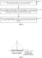
- FIG. 1 is a schematic diagram of an embodiment of a method for determining a movement track according to an embodiment of the present invention.
- an embodiment of the method for determining a movement track according to this embodiment of the present invention includes:
- a user equipment determines an action effect of an object instruction of a first mock object acting on a second mock object.
- the first mock object and the second mock object may be a character A and a character B, a character A and a monster B, or a monster A and a monster B in the game.
- the object instruction may be a fighting skill of a mock object in the game, such as a punch or a kick of the mock object.
- the punch or the kick for example, may be a heavy punch, a light punch, a heavy kick, or a light kick.
- the action effect is whether the first mock object hits the second mock object.
- the action effect may be understood as a level-1 heavy hit-away
- the action effect may be understood as a level-2 heavy hit-away
- the action effect may be understood as a level-1 light hit-away
- the action effect may be understood as a level-2 light hit-away
- the action effect may be understood as a level-2 light hit-away
- the user equipment obtains, from a preset track template set, a track template corresponding to the action effect, and obtains information about a staging environment in which the second mock object is located.
- a correspondence between various action effects and track templates may be indicated in a form of a table, or may be expressed in another form.
- the correspondence is described, for example, in a form of a table, and the correspondence between the various action effects and the track templates is shown in Table 1.
- Table 1 is merely an example for description. In fact, there may be a plurality of correspondences between the action effects and the track templates.
- an ID of a track template corresponds to the corresponding track template, and reference may be made to FIG. 2 for understanding of the track template.
- the heights and the widths of parabolas are different for different hitting-away effects.
- a movement track includes one primary curve segment and two secondary curve segments.
- the secondary curve segments are used to simulate the feeling of bouncing twice of a hit-away mock object after landing.
- the height and the width of a parabola of the level-1 heavy hit-away are greater than those of a parabola of the level-2 heavy hit-away.
- the height and the width of a parabola of the level-2 light hit-away are smallest in Table 1.
- the information about the staging environment in which the second mock object is located is about a topographical environment around the second mock object, for example, whether there is a pool, whether there is an obstacle, or whether a terrain is high or low.
- the user equipment determines a movement track of the second mock object according to the information about the staging environment and the track template.
- the second mock object After the second mock object is hit away, in the flying process, the second mock object may run into an obstacle or fall into water, or may encounter other situations, and may fail to move completely according to the curve shown in the track template. Therefore, a real template is most accurate only when the template is set according to the information about the staging environment.
- a user equipment determines an action effect of an object instruction of a first mock object acting on a second mock object; obtains a track template corresponding to the action effect, and obtains information about a staging environment in which the second mock object is located; and determines a movement track of the second mock object according to the information about the staging environment and the track template, so that the movement track can be determined according to an environment in which an acted-on mock object is currently located.
- Actual simulation of the movement track of the acted-on mock object can be implemented by using a small calculation amount.
- a server determines a landing location of the second mock object, generates landing location information of the second mock object, and sends the landing location information to the user equipment.
- the user equipment receives the landing location information of the second mock object, and determines, based on the landing location information, the movement track of the second mock object according to the information about the staging environment and the track template.
- the track template includes a predicted movement track of an object, and the predicted movement track includes a primary movement track, and the determining, by the user equipment, a movement track of the second mock object according to the information about the staging environment and the track template includes: determining, by the user equipment, the primary movement track of the predicted movement track according to the information about the staging environment.
- the predicted movement track further includes an auxiliary movement track
- the auxiliary movement track includes at least two segments of curves.
- the method before the obtaining, by the user equipment, information about a staging environment in which the second mock object is located, the method further includes:
- the actual flying is estimated as the curve shown in the track template, as shown in FIG. 2 .
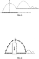
- FIG. 3 is a schematic diagram of a movement track of the hit-away mock object that is attacked by another hit-away in a hitting-way process.
- an initially calculated movement track is the track template shown in FIG. 2 .
- the hit-away mock object is attacked by another hit-away in the flying process, and then a new movement track is recalculated. That is, when the hit-away mock object is attacked by another hit-away when one segment of hit-away is not completed, a performance item of the current segment is canceled, and a new hitting-away curve is generated by using a current hit-away point as a starting point.
- FIG. 4 is a schematic diagram of a movement track of the hit-away mock object that takes a leap over a low obstacle in the hitting-away process.
- the user equipment determines the track template, if the user equipment determines that an obstacle in the flying process of the second mock object is lower than a flying point, the user equipment can determine that the second mock object will take a leap over the obstacle, and keep the original curve shown in the track template to complete the entire hitting-away process.
- FIG. 5 is a schematic diagram of a movement track of the hit-away mock object that runs into a high obstacle in the hitting-away process.
- the user equipment determines the track template, if the user equipment determines that an obstacle in the flying process of the second mock object is higher than the flying point, the user equipment can determine that the second mock object cannot take a leap over the obstacle, and will slide down along the obstacle, until a point at which the second mock object can land is calculated. In this way, the actual movement track becomes the movement track that is shown in FIG. 5 and shows that the second mock object does not complete the primary curve segment, and slides down along an obstacle when running into the obstacle until landing.
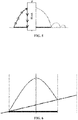
- FIG. 6 is a schematic diagram of a movement track showing that a hitting-away path is uphill.
- FIG. 7 is a schematic diagram of a movement track showing that a hitting-away path is downhill.
- a landing location calculated by the server is merely a location at which the second mock object falls into the water, and the server generates location information, and sends the location information to the user equipment.
- the user equipment determines the movement track.
- the user equipment determines, according to a buoyancy calculation formula, fluctuation of the second mock object in the water. Specifically, downward gravity, upward buoyancy, and upward viscous resistance will act on the second mock object after the second mock object falls into the water. The gravity does not change, and the buoyancy and the viscous resistance both change with the depth of the second mock object in the water. Therefore, the second mock object shows fluctuation in the water.
- the track template further includes sound information
- the determining, by the user equipment, a movement track of the second mock object according to the information about the staging environment and the track template includes: determining, by the user equipment, the sound information according to the information about the staging environment.
- an embodiment of a system for verifying a movement track includes: a first user equipment, a plurality of second user equipments (in the figure, an example in which there are two user equipments is used merely for description, and in fact, only one user equipment or many user equipments may be included), and a server.
- the first user equipment is configured to: determine an action effect of an object instruction of a first mock object acting on a second mock object; obtain, from a preset track template set, a track template corresponding to the action effect, and obtain information about a staging environment in which the second mock object is located; determine a movement track of the second mock object according to the information about the staging environment and the track template; and send the determined movement track of the second mock object to the server.
- the server is configured to: verify the movement track; send a response message to the first user equipment when the movement track is appropriate, the response message being used to instruct the first user equipment to control the second mock object to move according to the movement track; and generate a new movement track when the movement track is inappropriate, and send the new movement track to the first user equipment, so that the first user equipment controls the second mock object to move according to the new movement track.
- the server is further configured to:
- the system for verifying a movement track can ensure that configuration parameters are not maliciously modified, and ensure that movement tracks are all appropriate.
- the server can further control images on the user equipments to be all synchronous.
- FIG. 9 another embodiment of a system for verifying a movement track according to an embodiment of the present invention includes:
- the system for verifying a movement track can ensure that configuration parameters are not maliciously modified, and ensure that movement tracks are all appropriate.
- the server can further control images on the user equipments to be all synchronous.
- an embodiment of a user equipment according to an embodiment of the present invention includes:
- the user equipment can determine a movement track according to an environment in which an acted-on mock object is currently located. Actual simulation of the movement track of the acted-on mock object can be implemented by using a small calculation amount.
- the first determining unit 301 is configured to: determine a distance between the first mock object and the second mock object, and determine, according to the distance, the action effect of the object instruction acting on the second mock object.
- the action effect of the object instruction is determined by using the distance between the two mock objects, so that the efficiency of determining the action effect can be improved.
- the user equipment further includes: a receiving unit, configured to receive landing location information, sent by a server, of the second mock object.
- the landing location information is used to indicate a landing location of the second mock object.
- the second determining unit is further configured to determine, based on the received landing location information, the movement track of the second mock object according to the information about the staging environment and the track template.
- the track template includes a predicted movement track of an object, and the predicted movement track includes a primary movement track, and the second determining unit is further configured to determine the primary movement track of the predicted movement track according to the information about the staging environment.
- the track template includes sound information
- the second determining unit is further configured to determine the sound information according to the information about the staging environment.
- the predicted movement track further includes an auxiliary movement track
- the auxiliary movement track includes at least two segments of curves.
- the obtaining unit 302 is configured to determine, according to a preconfigured correspondence between various action effects and track templates, the track template corresponding to the action effect.
- the first determining unit 301 is further configured to: determine a movement direction of the second mock object according to a direction in which the action instruction acts on the second mock object, and determine a movement distance of the second mock object according to the action effect.
- the obtaining unit 302 is configured to obtain the information about the staging environment in the movement direction and within a range of the movement distance, the movement direction and the movement distance being determined by the first determining unit 301.
- the range in which the information about the staging environment is obtained is narrowed by determining the action direction and the movement distance, so that the obtaining efficiency is improved.
- the second determining unit 303 is configured to: adjust the track template according to the information about the staging environment in the movement direction and within the range of the movement distance, the information being obtained by the obtaining unit 302, and determine the movement track of the second mock object.
- the track template is adjusted according to the information about the staging environment in the movement direction and within the range of the movement distance, so that the obtained movement track can be ensured to be more accurate.
- FIG. 11 is a schematic structural diagram of a user equipment 30 according to an embodiment of the present invention.
- the user equipment 30 is applied to a system for verifying a movement track.
- the system for verifying a movement track includes a user equipment and a server.
- the user equipment 30 includes a processor 310, a memory 350, and an input/output (I/O) device 330.
- the memory 350 may include a read-only memory (ROM) and a random access memory (RAM), and provides operating instructions and data to the processor 310.
- a part of the memory 350 may further include a nonvolatile random access memory (NVRAM).
- NVRAM nonvolatile random access memory
- the memory 350 stores the following elements, executable modules, or data structures, or subsets thereof, or extended sets thereof:
- the user equipment can determine a movement track according to an environment in which an acted-on mock object is currently located. Actual simulation of the movement track of the acted-on mock object can be implemented by using a small calculation amount.
- the processor 310 controls operation of the user equipment 30.
- the processor 310 may also be referred to as a central processing unit (CPU).
- the memory 350 may include a ROM and a RAM, and provides instructions and data to the processor 310. A part of the memory 350 may further include an NVRAM.
- components in the user equipment 30 are coupled together by using a bus system 320.
- the bus system 320 may also include a power supply bus, a control bus, a status signal bus, and the like in addition to a data bus. However, to clarify the description, the buses are all marked as the bus system 320 in the figure.
- the foregoing method disclosed in the embodiments of the present invention may be applied to the processor 310, or implemented by the processor 310.
- the processor 310 may be an integrated circuit chip, and has a signal processing capability. In an implementation process, steps of the foregoing method may be completed by using an integrated logic circuit of hardware in the processor 310 or an instruction in a software form.
- the foregoing processor 310 may be a general purpose processor, a digital signal processor (DSP), an application-specific integrated circuit (ASIC), a field programmable gate array (FPGA) or another programmable logic device, a discrete gate, a transistor logic device, or a discrete hardware component.
- DSP digital signal processor
- ASIC application-specific integrated circuit
- FPGA field programmable gate array
- the processor 310 can implement or perform the methods, steps, and logic block diagrams disclosed in the embodiments of the present invention.
- the general purpose processor may be a microprocessor, any conventional processor, or the like. Steps of the method disclosed with reference to the embodiments of the present invention may be directly reflected as being performed and completed by a hardware decoding processor, or by a combination of hardware and software modules in the decoding processor.
- the software module may be located in a mature storage medium in the art such as a RAM, a flash memory, a ROM, a programmable ROM, an electrically erasable programmable memory, or a register.
- the storage medium is located in the memory 350.
- the processor 310 reads information in the memory 350. Steps of the foregoing method are completed in combination with hardware thereof.
- the processor 310 is configured to: determine a distance between the first mock object and the second mock object, and determine, according to the distance, the action effect of the object instruction acting on the second mock object.
- the processor 310 is configured to: determine, according to a preconfigured correspondence between various action effects and track templates, the track template corresponding to the action effect.
- the processor 310 is configured to: determine a movement direction of the second mock object according to a direction in which the action instruction acts on the second mock object, determine a movement distance of the second mock object according to the action effect, and obtain information about the staging environment in the movement direction and within a range of the movement distance.
- the processor 310 is configured to: adjust the track template according to the information about the staging environment in the movement direction and within the range of the movement distance, and determine the movement track of the second mock object.
- the I/O device 330 is configured to send the determined movement track of the second mock object to the server, so that the server verifies the movement track.
- the program may be stored in a computer readable storage medium.
- the storage medium may include: a ROM, a RAM, a magnetic disk, an optical disc, or the like.
Landscapes
- Engineering & Computer Science (AREA)
- Multimedia (AREA)
- Human Computer Interaction (AREA)
- Theoretical Computer Science (AREA)
- Physics & Mathematics (AREA)
- General Physics & Mathematics (AREA)
- General Engineering & Computer Science (AREA)
- Acoustics & Sound (AREA)
- Processing Or Creating Images (AREA)
- Radar, Positioning & Navigation (AREA)
- Remote Sensing (AREA)
- Automation & Control Theory (AREA)
- User Interface Of Digital Computer (AREA)
Abstract
Description
- This application claims priority to Chinese Patent Application No.
201610071125.2 - The present disclosure relates to the field of computer technologies, and specifically, to a method for determining a movement track, and a user equipment.
- In some current applications, there are usually scenarios in which mock objects send object instructions to each other, and interact with each other. Two mock objects interact with each other or a plurality of mock objects interacts with each other. In the process in which mock objects interact with each other, a particular mock object is usually acted on to move by a long distance or a short distance.
- A movement track of the acted-on mock object is usually implemented by means of two solutions: one solution is to prefabricate the movement track of the acted-on mock object by a developer, and the other solution is to simulate the movement track of the acted-on mock object by means of calculation by using a machine engine.
- However, there are many cases in which mock objects affect each other. It is impossible for a developer to prefabricate a movement track for each case in which a mock object is acted on. The machine engine calculation manner can be used merely for a case of a moment at which a mock object is acted on. In fact, a mock object may experience many changes in a movement process. Consequently, a movement track calculated by a machine engine usually fails to conform to a current scenario.
- An embodiment of the present invention provides a method for determining a movement track, so that the movement track can be determined according to an environment in which an acted-on mock object is currently located. Actual simulation of the movement track of the acted-on mock object can be implemented by using a small calculation amount. An embodiment of the present invention further provides a corresponding user equipment.
- A first aspect of the present disclosure provides a method for determining a movement track, including:
- determining, by a user equipment, an action effect of an object instruction of a first mock object acting on a second mock object;
- obtaining, by the user equipment from a preset track template set, a track template corresponding to the action effect, and obtaining information about a staging environment in which the second mock object is located; and
- determining, by the user equipment, a movement track of the second mock object according to the information about the staging environment and the track template.
- A second aspect of the present disclosure provides a user equipment, including:
- a first determining unit, configured to determine an action effect of an object instruction of a first mock object acting on a second mock object;
- an obtaining unit, configured to: obtain, from a preset track template set, a track template corresponding to the action effect determined by the first determining unit, and obtain information about a staging environment in which the second mock object is located; and
- a second determining unit, configured to determine a movement track of the second mock object according to the information about the staging environment and the track template that are obtained by the obtaining unit.
- As compared with the existing technology, in which the complexity of manually fabricating a movement track is high, and a movement track that fails to conform to a current scenario is usually obtained by means of machine calculation, according to the method for determining a movement track provided in the embodiments of the present invention, a user equipment determines an action effect of an object instruction of a first mock object acting on a second mock object; obtains a track template corresponding to the action effect, and obtains information about a staging environment in which the second mock object is located; and determines a movement track of the second mock object according to the information about the staging environment and the track template, so that the movement track can be determined according to an environment in which an acted-on mock object is currently located. Actual simulation of the movement track of the acted-on mock object can be implemented by using a small calculation amount.
- To describe the technical solutions in the embodiments of the present invention more clearly, the following briefly introduces the accompanying drawings required for describing the embodiments. Apparently, the accompanying drawings in the following description show merely some embodiments of the present invention, and a person skilled in the art may still derive other drawings from these accompanying drawings without creative efforts.
-
FIG. 1 is a schematic diagram of an embodiment of a method for determining a movement track according to an embodiment of the present invention; -
FIG. 2 is an exemplary schematic diagram of a track template according to an embodiment of the present invention; -
FIG. 3 is an exemplary schematic diagram of a determined movement track according to an embodiment of the present invention; -
FIG. 4 is another exemplary schematic diagram of a determined movement track according to an embodiment of the present invention; -
FIG. 5 is still another exemplary schematic diagram of a determined movement track according to an embodiment of the present invention; -
FIG. 6 is still yet another exemplary schematic diagram of a determined movement track according to an embodiment of the present invention; -
FIG. 7 is a still further exemplary schematic diagram of a determined movement track according to an embodiment of the present invention; -
FIG. 8 is a schematic diagram of an embodiment of a system for verifying a movement track according to an embodiment of the present invention; -
FIG. 9 is a schematic diagram of another embodiment of a system for verifying a movement track according to an embodiment of the present invention; -
FIG. 10 is a schematic diagram of an embodiment of a user equipment according to an embodiment of the present invention; and -
FIG. 11 is a schematic diagram of another embodiment of a user equipment according to an embodiment of the present invention. - An embodiment of the present invention provides a method for determining a movement track, so that the movement track can be determined according to an environment in which an acted-on mock object is currently located. Actual simulation of the movement track of the acted-on mock object can be implemented by using a small calculation amount. Embodiments of the present invention further provide a corresponding user equipment and system. Detailed descriptions are separately provided below.
- The following clearly and completely describes the technical solutions in the embodiments of the present invention with reference to the accompanying drawings in the embodiments of the present invention. Apparently, the described embodiments are merely some but not all of the embodiments of the present invention. All other embodiments obtained by a person skilled in the art based on the embodiments of the present invention without creative efforts shall fall within the protection scope of the present disclosure.
- With the popularization of the Internet, the game industry has been rapidly developed accordingly. In games, there are a relatively large number of fighting games, including fights between two players, fights between multiple players, standalone fights, or online fights. In particular, the current massively multiplayer online (MMO) game is very popular, and the MMO game is the massively multiple-player online role-playing game (MMORPG). There are a large number of fighting scenes in a game of this type. Usually, hundreds of players are involved in fights simultaneously. In the fighting process, characters are usually hit away. Certainly, the MMO game is used merely as an example for description herein, and the case in which characters or monsters are hit away usually exists in many game scenes. Characters and monsters can both be referred to as mock objects. Hitting away may include kicking away by using a foot, punching away by using a fist, knocking away by using a body, beating away by using a weapon, and the like.
- In a fight, the performance of simulation in the hit-away flying process and the falling-to-the ground process of a hit-away party plays an important role to a refreshing feeling of the fight. Therefore, a movement track of a hit-away mock object in a hitting-away scene is of great significance. Therefore, in the embodiments of the present invention, how to determine the movement track of the hit-away mock object is described next.
- In this application, a curve of the movement track of the hit-away mock object may be divided into three parabolas: one primary curve and two segments of secondary curves. The primary curve may be understood as a dynamic adjustment segment, and the two segments of secondary curves are supplemented performance segments. The dynamic adjustment segment has different performance curves based on the topography of an environment in which a mock object is located. When running into a high obstacle, the mock object slides down along the obstacle, takes a leap over a low obstacle, and sinks down and floats up in water after falling into water. In the hitting-away process, corresponding performance items of animations, sounds, and special effects also change accordingly. The auxiliary performance segments are two segments of small parabolas, and can alleviate the rigid performance of landing by means of one segment of curve.
- Developers may set several sets of basic templates for the hitting-away solution. For example, five sets of basic templates of a heavy hit-away and five sets of basic templates of a light hit-away may be set, and then when intending to add a template, the developers need to select only one basic template, and configure parameters such as the hitting-away distance, height, floating time, and falling-to-the-ground time on the basic template, so as to obtain a new hitting-away template. In this way, configuration parameters of the new hitting-away template need to include only parameters such as an identifier (ID) of the basic template and the hitting-away distance, height, floating time, and falling-to-the-ground time, thereby greatly reducing the workload of configuring hitting-away templates by the developers.
- After the basic templates are configured, in the process of playing the game by players, a user equipment may determine the movement track of the hit-away mock object according to the fighting situation of the mock objects in the game.
-
FIG. 1 is a schematic diagram of an embodiment of a method for determining a movement track according to an embodiment of the present invention. - Referring to
FIG. 1 , an embodiment of the method for determining a movement track according to this embodiment of the present invention includes: - 101. A user equipment determines an action effect of an object instruction of a first mock object acting on a second mock object.
- The first mock object and the second mock object may be a character A and a character B, a character A and a monster B, or a monster A and a monster B in the game. The object instruction may be a fighting skill of a mock object in the game, such as a punch or a kick of the mock object. The punch or the kick, for example, may be a heavy punch, a light punch, a heavy kick, or a light kick. The action effect is whether the first mock object hits the second mock object. For example, if the first mock object hits the second mock object by means of a heavy kick, the action effect may be understood as a level-1 heavy hit-away, if the first mock object hits the second mock object by means of a heavy punch, the action effect may be understood as a level-2 heavy hit-away, if the first mock object hits the second mock object by means of a light kick, the action effect may be understood as a level-1 light hit-away, and if the first mock object hits the second mock object by means of a light punch, the action effect may be understood as a level-2 light hit-away. Certainly, several examples are listed herein merely for understanding. In an actual game scene, there are many fighting skills, and action effects may also be divided into many cases.
- 102. The user equipment obtains, from a preset track template set, a track template corresponding to the action effect, and obtains information about a staging environment in which the second mock object is located.
- A correspondence between various action effects and track templates may be indicated in a form of a table, or may be expressed in another form. In this application, the correspondence is described, for example, in a form of a table, and the correspondence between the various action effects and the track templates is shown in Table 1.
Table 1 Action effect ID of a track template Level-1 heavy hit-away Template 1 Level-2 heavy hit-away Template 2 Level-1 light hit-away Template 3 Level-2 light hit-away Template 4 - Table 1 is merely an example for description. In fact, there may be a plurality of correspondences between the action effects and the track templates.
- Certainly, an ID of a track template corresponds to the corresponding track template, and reference may be made to
FIG. 2 for understanding of the track template. In different track templates, the heights and the widths of parabolas are different for different hitting-away effects. - As shown in
FIG. 2 , a movement track includes one primary curve segment and two secondary curve segments. The secondary curve segments are used to simulate the feeling of bouncing twice of a hit-away mock object after landing. - For example, the height and the width of a parabola of the level-1 heavy hit-away are greater than those of a parabola of the level-2 heavy hit-away. By such analogy, the height and the width of a parabola of the level-2 light hit-away are smallest in Table 1.
- The information about the staging environment in which the second mock object is located is about a topographical environment around the second mock object, for example, whether there is a pool, whether there is an obstacle, or whether a terrain is high or low.
- 103. The user equipment determines a movement track of the second mock object according to the information about the staging environment and the track template.
- After the second mock object is hit away, in the flying process, the second mock object may run into an obstacle or fall into water, or may encounter other situations, and may fail to move completely according to the curve shown in the track template. Therefore, a real template is most accurate only when the template is set according to the information about the staging environment.
- As compared with the existing technology, in which the complexity of manually fabricating a movement track is high, and a movement track that fails to conform to a current scenario is usually obtained by means of machine calculation, according to the method for determining a movement track provided in the embodiments of the present invention, a user equipment determines an action effect of an object instruction of a first mock object acting on a second mock object; obtains a track template corresponding to the action effect, and obtains information about a staging environment in which the second mock object is located; and determines a movement track of the second mock object according to the information about the staging environment and the track template, so that the movement track can be determined according to an environment in which an acted-on mock object is currently located. Actual simulation of the movement track of the acted-on mock object can be implemented by using a small calculation amount.
- In an embodiment of the present invention, a server determines a landing location of the second mock object, generates landing location information of the second mock object, and sends the landing location information to the user equipment. The user equipment receives the landing location information of the second mock object, and determines, based on the landing location information, the movement track of the second mock object according to the information about the staging environment and the track template.
- In an embodiment of the present invention, the track template includes a predicted movement track of an object, and the predicted movement track includes a primary movement track, and
the determining, by the user equipment, a movement track of the second mock object according to the information about the staging environment and the track template includes:
determining, by the user equipment, the primary movement track of the predicted movement track according to the information about the staging environment. - In addition, the predicted movement track further includes an auxiliary movement track, and the auxiliary movement track includes at least two segments of curves.
- In an embodiment of the present invention, before the obtaining, by the user equipment, information about a staging environment in which the second mock object is located, the method further includes:
- determining, by the user equipment, a movement direction of the second mock object according to a direction in which the action instruction acts on the second mock object; and
- determining, by the user equipment, a movement distance of the second mock object according to the action effect; and
- the obtaining, by the user equipment, information about a staging environment in which the second mock object is located includes:
obtaining, by the user equipment, the information about the staging environment in the movement direction and within a range of the movement distance. - Specifically, the determined actual track may be understood with reference to the following accompanying drawings.
- If the information about the staging environment in which the second mock object is located is about a flat ground on which there is no obstacle, the actual flying is estimated as the curve shown in the track template, as shown in
FIG. 2 . -
FIG. 3 is a schematic diagram of a movement track of the hit-away mock object that is attacked by another hit-away in a hitting-way process. - In this case, an initially calculated movement track is the track template shown in
FIG. 2 . However, the hit-away mock object is attacked by another hit-away in the flying process, and then a new movement track is recalculated. That is, when the hit-away mock object is attacked by another hit-away when one segment of hit-away is not completed, a performance item of the current segment is canceled, and a new hitting-away curve is generated by using a current hit-away point as a starting point. -
FIG. 4 is a schematic diagram of a movement track of the hit-away mock object that takes a leap over a low obstacle in the hitting-away process. - After the user equipment determines the track template, if the user equipment determines that an obstacle in the flying process of the second mock object is lower than a flying point, the user equipment can determine that the second mock object will take a leap over the obstacle, and keep the original curve shown in the track template to complete the entire hitting-away process.
-
FIG. 5 is a schematic diagram of a movement track of the hit-away mock object that runs into a high obstacle in the hitting-away process. - After the user equipment determines the track template, if the user equipment determines that an obstacle in the flying process of the second mock object is higher than the flying point, the user equipment can determine that the second mock object cannot take a leap over the obstacle, and will slide down along the obstacle, until a point at which the second mock object can land is calculated. In this way, the actual movement track becomes the movement track that is shown in
FIG. 5 and shows that the second mock object does not complete the primary curve segment, and slides down along an obstacle when running into the obstacle until landing. -
FIG. 6 is a schematic diagram of a movement track showing that a hitting-away path is uphill. - As shown in
FIG. 6 , if the hitting-away path is uphill, the landing point changes, and the actual movement track becomes the curve shown inFIG. 6 . -
FIG. 7 is a schematic diagram of a movement track showing that a hitting-away path is downhill. - As shown in
FIG. 7 , if the hitting-away path is downhill, the landing point changes, and the actual movement track becomes the curve shown inFIG. 7 . - If the second mock object falls into water after being hit away, the second mock object fluctuates in the water. In this case, a landing location calculated by the server is merely a location at which the second mock object falls into the water, and the server generates location information, and sends the location information to the user equipment. After receiving the location information, the user equipment determines the movement track. In addition, the user equipment determines, according to a buoyancy calculation formula, fluctuation of the second mock object in the water. Specifically, downward gravity, upward buoyancy, and upward viscous resistance will act on the second mock object after the second mock object falls into the water. The gravity does not change, and the buoyancy and the viscous resistance both change with the depth of the second mock object in the water. Therefore, the second mock object shows fluctuation in the water.
- In addition, in an embodiment of the present invention, the track template further includes sound information, and
the determining, by the user equipment, a movement track of the second mock object according to the information about the staging environment and the track template includes:
determining, by the user equipment, the sound information according to the information about the staging environment. - In the foregoing embodiment, description of the movement track is emphasized. In fact, animations, sound effects, special effects, and the like are further configured on track templates.
- Referring to
FIG. 8 , an embodiment of a system for verifying a movement track according to an embodiment of the present invention includes: a first user equipment, a plurality of second user equipments (in the figure, an example in which there are two user equipments is used merely for description, and in fact, only one user equipment or many user equipments may be included), and a server. - The first user equipment is configured to: determine an action effect of an object instruction of a first mock object acting on a second mock object; obtain, from a preset track template set, a track template corresponding to the action effect, and obtain information about a staging environment in which the second mock object is located; determine a movement track of the second mock object according to the information about the staging environment and the track template; and send the determined movement track of the second mock object to the server.
- The server is configured to: verify the movement track;
send a response message to the first user equipment when the movement track is appropriate, the response message being used to instruct the first user equipment to control the second mock object to move according to the movement track; and
generate a new movement track when the movement track is inappropriate, and send the new movement track to the first user equipment, so that the first user equipment controls the second mock object to move according to the new movement track. - Optionally, the server is further configured to:
- send the movement track and an identifier of the second mock object to each second user equipment when the movement track is appropriate, so that each second user equipment controls the second mock object to move according to the movement track; and
- send the new movement track and the identifier of the second mock object to each second user equipment when the movement track is inappropriate, so that each second user equipment controls the second mock object to move according to the new movement track.
- The system for verifying a movement track according to this embodiment of the present invention can ensure that configuration parameters are not maliciously modified, and ensure that movement tracks are all appropriate. In addition, the server can further control images on the user equipments to be all synchronous.
- Referring to
FIG. 9 , another embodiment of a system for verifying a movement track according to an embodiment of the present invention includes: - 201. A first user equipment determines an action effect of an object instruction of a first mock object acting on a second mock object.
- 202. The first user equipment obtains a track template corresponding to the action effect, and obtains information about a staging environment in which the second mock object is located.
- 203. The first user equipment determines a movement track of the second mock object according to the information about the staging environment and the track template.
- 204. The first user equipment sends the determined movement track of the second mock object to a server.
- 205. The server verifies the movement track of the second mock object, and performs
steps 206 to 209 when a verification result is that the movement track is appropriate, and performssteps 210 to 214 when the verification result is that the movement track is inappropriate. - 206. The server sends a response message to the first user equipment.
- 207. The server sends the movement track of the second mock object and an identifier of the second mock object to a second user equipment.
- 208. The first user equipment controls, according to the response message, the second mock object to move according to the movement track.
- 209. The second user equipment controls the second mock object to move according to the movement track.
There may be a plurality of second user equipments, and only one second user equipment is drawn inFIG. 9 for exemplary description. - 210. When the verification result is that the movement track is inappropriate, the server generates a new movement track.
- 211. The server sends the new movement track to the first user equipment.
- 212. The server sends the new movement track and an identifier of the second mock object to the first user equipment.
- 213. The first user equipment controls the second mock object to move according to the new movement track.
- 214. The second user equipment controls the second mock object to move according to the new movement track.
- The system for verifying a movement track according to this embodiment of the present invention can ensure that configuration parameters are not maliciously modified, and ensure that movement tracks are all appropriate. In addition, the server can further control images on the user equipments to be all synchronous.
- Referring to
FIG. 10 , an embodiment of a user equipment according to an embodiment of the present invention includes: - a first determining unit 301, configured to determine an action effect of an object instruction of a first mock object acting on a second mock object;
- an obtaining unit 302, configured to: obtain, from a preset track template set, a track template corresponding to the action effect determined by the first determining unit 301, and obtain information about a staging environment in which the second mock object is located; and
- a second determining unit 303, configured to determine a movement track of the second mock object according to the information about the staging environment and the track template that are obtained by the obtaining unit 302.
- The user equipment according to this embodiment of the present invention can determine a movement track according to an environment in which an acted-on mock object is currently located. Actual simulation of the movement track of the acted-on mock object can be implemented by using a small calculation amount.
- Optionally, based on the foregoing embodiment corresponding to
FIG. 10 , in an optional embodiment of the user equipment according to this embodiment of the present invention,
the first determining unit 301 is configured to: determine a distance between the first mock object and the second mock object, and determine, according to the distance, the action effect of the object instruction acting on the second mock object. - In this embodiment of the present invention, the action effect of the object instruction is determined by using the distance between the two mock objects, so that the efficiency of determining the action effect can be improved.
- Optionally, based on the foregoing embodiment corresponding to
FIG. 10 , in another embodiment of the present invention, the user equipment further includes: a receiving unit, configured to receive landing location information, sent by a server, of the second mock object. The landing location information is used to indicate a landing location of the second mock object. - In an embodiment of the present invention, the second determining unit is further configured to determine, based on the received landing location information, the movement track of the second mock object according to the information about the staging environment and the track template.
- In an embodiment of the present invention, the track template includes a predicted movement track of an object, and the predicted movement track includes a primary movement track, and
the second determining unit is further configured to determine the primary movement track of the predicted movement track according to the information about the staging environment. - In an embodiment of the present invention, the track template includes sound information, and
the second determining unit is further configured to determine the sound information according to the information about the staging environment. - In an embodiment of the present invention, the predicted movement track further includes an auxiliary movement track, and the auxiliary movement track includes at least two segments of curves.
- In an embodiment of the present invention, the obtaining unit 302 is configured to determine, according to a preconfigured correspondence between various action effects and track templates, the track template corresponding to the action effect.
- Optionally, in the user equipment according to this embodiment of the present invention, the first determining unit 301 is further configured to: determine a movement direction of the second mock object according to a direction in which the action instruction acts on the second mock object, and determine a movement distance of the second mock object according to the action effect.
- The obtaining unit 302 is configured to obtain the information about the staging environment in the movement direction and within a range of the movement distance, the movement direction and the movement distance being determined by the first determining unit 301.
- In this embodiment of the present invention, the range in which the information about the staging environment is obtained is narrowed by determining the action direction and the movement distance, so that the obtaining efficiency is improved.
- Optionally, based on the foregoing optional embodiment of the user equipment, in the user equipment according to this embodiment of the present invention, the second determining unit 303 is configured to: adjust the track template according to the information about the staging environment in the movement direction and within the range of the movement distance, the information being obtained by the obtaining unit 302, and determine the movement track of the second mock object.
- According to this embodiment of the present invention, the track template is adjusted according to the information about the staging environment in the movement direction and within the range of the movement distance, so that the obtained movement track can be ensured to be more accurate.
-
FIG. 11 is a schematic structural diagram of auser equipment 30 according to an embodiment of the present invention. Theuser equipment 30 is applied to a system for verifying a movement track. The system for verifying a movement track includes a user equipment and a server. Theuser equipment 30 includes aprocessor 310, amemory 350, and an input/output (I/O)device 330. Thememory 350 may include a read-only memory (ROM) and a random access memory (RAM), and provides operating instructions and data to theprocessor 310. A part of thememory 350 may further include a nonvolatile random access memory (NVRAM). - In some implementations, the
memory 350 stores the following elements, executable modules, or data structures, or subsets thereof, or extended sets thereof: - in an embodiment of the present invention, by calling the operating instructions stored in the memory 350 (the operating instructions may be stored in an operating system),
- an action effect of an object instruction of a first mock object acting on a second mock object is determined,
- a track template corresponding to the action effect is obtained from a preset track template set, and information about a staging environment in which the second mock object is located is obtained, and
- a movement track of the second mock object is determined according to the information about the staging environment and the track template.
- As compared with the existing technology, in which the complexity of manually fabricating a movement track is high, and a movement track that fails to conform to a current scenario is usually obtained by means of machine calculation, the user equipment according to this embodiment of the present invention can determine a movement track according to an environment in which an acted-on mock object is currently located. Actual simulation of the movement track of the acted-on mock object can be implemented by using a small calculation amount.
- The
processor 310 controls operation of theuser equipment 30. Theprocessor 310 may also be referred to as a central processing unit (CPU). Thememory 350 may include a ROM and a RAM, and provides instructions and data to theprocessor 310. A part of thememory 350 may further include an NVRAM. In specific application, components in theuser equipment 30 are coupled together by using abus system 320. Thebus system 320 may also include a power supply bus, a control bus, a status signal bus, and the like in addition to a data bus. However, to clarify the description, the buses are all marked as thebus system 320 in the figure. - The foregoing method disclosed in the embodiments of the present invention may be applied to the
processor 310, or implemented by theprocessor 310. Theprocessor 310 may be an integrated circuit chip, and has a signal processing capability. In an implementation process, steps of the foregoing method may be completed by using an integrated logic circuit of hardware in theprocessor 310 or an instruction in a software form. The foregoingprocessor 310 may be a general purpose processor, a digital signal processor (DSP), an application-specific integrated circuit (ASIC), a field programmable gate array (FPGA) or another programmable logic device, a discrete gate, a transistor logic device, or a discrete hardware component. Theprocessor 310 can implement or perform the methods, steps, and logic block diagrams disclosed in the embodiments of the present invention. The general purpose processor may be a microprocessor, any conventional processor, or the like. Steps of the method disclosed with reference to the embodiments of the present invention may be directly reflected as being performed and completed by a hardware decoding processor, or by a combination of hardware and software modules in the decoding processor. The software module may be located in a mature storage medium in the art such as a RAM, a flash memory, a ROM, a programmable ROM, an electrically erasable programmable memory, or a register. The storage medium is located in thememory 350. Theprocessor 310 reads information in thememory 350. Steps of the foregoing method are completed in combination with hardware thereof. - Optionally, the
processor 310 is configured to: determine a distance between the first mock object and the second mock object, and determine, according to the distance, the action effect of the object instruction acting on the second mock object. - Optionally, the
processor 310 is configured to: determine, according to a preconfigured correspondence between various action effects and track templates, the track template corresponding to the action effect. - Optionally, the
processor 310 is configured to: determine a movement direction of the second mock object according to a direction in which the action instruction acts on the second mock object, determine a movement distance of the second mock object according to the action effect, and obtain information about the staging environment in the movement direction and within a range of the movement distance. - Optionally, the
processor 310 is configured to: adjust the track template according to the information about the staging environment in the movement direction and within the range of the movement distance, and determine the movement track of the second mock object. - Optionally, the I/
O device 330 is configured to send the determined movement track of the second mock object to the server, so that the server verifies the movement track. - Reference may be made to some of the descriptions of
FIG. 1 to FIG. 10 for understanding of the foregoinguser equipment 30. Details are not described herein again. - A person of ordinary skill in the art may understand that all or some of the steps of the methods in the foregoing embodiments may be completed by a program instructing relevant hardware. The program may be stored in a computer readable storage medium. The storage medium may include: a ROM, a RAM, a magnetic disk, an optical disc, or the like.
- The method for determining a movement track, the user equipment, and the system according to the embodiments of the present invention are described above in detail. Although the principles and implementations of the present disclosure are described by using specific examples in this specification, the descriptions of the foregoing embodiments are merely intended to help understand the method and the core idea thereof of the present disclosure. Meanwhile, a person of ordinary skill in the art may make modifications to both the specific implementations and the application range according to the idea of the present disclosure. In conclusion, the content of this specification should not be construed as a limitation to the present disclosure.
Claims (21)
- A method for determining a movement track, comprising:determining, by a user equipment, an action effect of an object instruction of a first mock object acting on a second mock object;obtaining, by the user equipment from a preset track template set, a track template corresponding to the action effect, and obtaining information about a staging environment in which the second mock object is located; anddetermining, by the user equipment, a movement track of the second mock object according to the information about the staging environment and the track template.
- The method according to claim 1, wherein the determining, by a user equipment, an action effect of an object instruction of a first mock object acting on a second mock object comprises:determining, by the user equipment, a distance between the first mock object and the second mock object; anddetermining, by the user equipment according to the distance, the action effect of the object instruction acting on the second mock object.
- The method according to claim 1, further comprising:
receiving, by the user equipment, landing location information, sent by a server, of the second mock object, the landing location information being used to indicate a landing location of the second mock object. - The method according to claim 3, wherein the determining, by the user equipment, a movement track of the second mock object according to the information about the staging environment and the track template comprises:
determining, by the user equipment based on the received landing location information, the movement track of the second mock object according to the information about the staging environment and the track template. - The method according to claim 1, wherein the track template comprises a predicted movement track of an object, and the predicted movement track comprises a primary movement track, and
the determining, by the user equipment, a movement track of the second mock object according to the information about the staging environment and the track template comprises:determining, by the user equipment, the primary movement track of the predicted movement track according to the information about the staging environment. - The method according to claim 5, wherein the track template comprises sound information, and
the determining, by the user equipment, a movement track of the second mock object according to the information about the staging environment and the track template comprises:
determining, by the user equipment, the sound information according to the information about the staging environment. - The method according to claim 5, wherein the predicted movement track further comprises an auxiliary movement track, and the auxiliary movement track comprises at least two segments of curves.
- The method according to claim 1, wherein the obtaining, by the user equipment, a track template corresponding to the action effect comprises:
determining, by the user equipment according to a preconfigured correspondence between various action effects and track templates, the track template corresponding to the action effect. - The method according to claim 1, wherein before the obtaining, by the user equipment, information about a staging environment in which the second mock object is located, the method further comprises:determining, by the user equipment, a movement direction of the second mock object according to a direction in which the action instruction acts on the second mock object; anddetermining, by the user equipment, a movement distance of the second mock object according to the action effect; andthe obtaining, by the user equipment, information about a staging environment in which the second mock object is located comprises:
obtaining, by the user equipment, the information about the staging environment in the movement direction and within a range of the movement distance. - The method according to claim 9, wherein the determining, by the user equipment according to the distance, the action effect of the object instruction acting on the second mock object comprises:
adjusting the track template according to the obtained information about the staging environment in the movement direction and within the range of the movement distance, and determining the movement track of the second mock object. - A user equipment, comprising:a first determining unit, configured to determine an action effect of an object instruction of a first mock object acting on a second mock object;an obtaining unit, configured to: obtain, from a preset track template set, a track template corresponding to the action effect determined by the first determining unit, and obtain information about a staging environment in which the second mock object is located; anda second determining unit, configured to determine a movement track of the second mock object according to the information about the staging environment and the track template that are obtained by the obtaining unit.
- The user equipment according to claim 11, wherein
the first determining unit is further configured to: determine a distance between the first mock object and the second mock object, and determine, according to the distance, the action effect of the object instruction acting on the second mock object. - The user equipment according to claim 11, further comprising:
a receiving unit, configured to receive landing location information, sent by a server, of the second mock object, the landing location information being used to indicate a landing location of the second mock object. - The user equipment according to claim 13, wherein the second determining unit is further configured to determine, based on the received landing location information, the movement track of the second mock object according to the information about the staging environment and the track template.
- The user equipment according to claim 11, wherein the track template comprises a predicted movement track of an object, and the predicted movement track comprises a primary movement track, and
the second determining unit is further configured to determine the primary movement track of the predicted movement track according to the information about the staging environment. - The user equipment according to claim 15, wherein the track template comprises sound information, and
the second determining unit is further configured to determine the sound information according to the information about the staging environment. - The user equipment according to claim 15, wherein the predicted movement track further comprises an auxiliary movement track, and the auxiliary movement track comprises at least two segments of curves.
- The user equipment according to claim 15, wherein
the obtaining unit is configured to determine, according to a preconfigured correspondence between various action effects and track templates, the track template corresponding to the action effect. - The user equipment according to claim 11, wherein
the first determining unit is further configured to: determine a movement direction of the second mock object according to a direction in which the action instruction acts on the second mock object, and determine a movement distance of the second mock object according to the action effect; and
the obtaining unit is configured to obtain the information about the staging environment in the movement direction and within a range of the movement distance, the movement direction and the movement distance being determined by the first determining unit. - The user equipment according to claim 19, wherein
the second determining unit is configured to: adjust the track template according to the information about the staging environment in the movement direction and within the range of the movement distance, the information being obtained by the obtaining unit, and determine the movement track of the second mock object. - A nonvolatile storage medium storing operating instructions, wherein a processor performs the method for determining a movement track according to claims 1 to 10 when executing the stored operating instructions.
Applications Claiming Priority (2)
| Application Number | Priority Date | Filing Date | Title |
|---|---|---|---|
| CN201610071125.2A CN107019915B (en) | 2016-02-01 | 2016-02-01 | A kind of method, user equipment and the system of determining motion track |
| PCT/CN2017/072541 WO2017133601A1 (en) | 2016-02-01 | 2017-01-25 | Method for determining a movement trace, and user equipment |
Publications (3)
| Publication Number | Publication Date |
|---|---|
| EP3412349A1 true EP3412349A1 (en) | 2018-12-12 |
| EP3412349A4 EP3412349A4 (en) | 2019-08-21 |
| EP3412349B1 EP3412349B1 (en) | 2023-01-11 |
Family
ID=59499425
Family Applications (1)
| Application Number | Title | Priority Date | Filing Date |
|---|---|---|---|
| EP17746921.0A Active EP3412349B1 (en) | 2016-02-01 | 2017-01-25 | Method for determining a movement trace, and user equipment |
Country Status (6)
| Country | Link |
|---|---|
| US (1) | US10549196B2 (en) |
| EP (1) | EP3412349B1 (en) |
| JP (1) | JP6904952B2 (en) |
| KR (1) | KR102111870B1 (en) |
| CN (1) | CN107019915B (en) |
| WO (1) | WO2017133601A1 (en) |
Families Citing this family (16)
| Publication number | Priority date | Publication date | Assignee | Title |
|---|---|---|---|---|
| US11003183B2 (en) * | 2017-09-13 | 2021-05-11 | Baidu Usa Llc | Driving scene based path planning for autonomous driving vehicles |
| CN107837530B (en) * | 2017-11-06 | 2021-11-16 | 网易(杭州)网络有限公司 | Game synchronization method, device and equipment |
| CN108305330A (en) * | 2018-01-15 | 2018-07-20 | 石化盈科信息技术有限责任公司 | A kind of methods of exhibiting of 3D scenes and the electronic equipment for 3D scene displays |
| CN108429793B (en) * | 2018-02-11 | 2021-10-08 | 鲸彩在线科技(大连)有限公司 | Vehicle physics simulation method, system, client, electronic device and server |
| CN110170169B (en) * | 2019-06-05 | 2021-03-26 | 腾讯科技(深圳)有限公司 | Information display method and device, storage medium and electronic device |
| CN111054074B (en) * | 2019-12-27 | 2023-04-07 | 网易(杭州)网络有限公司 | Method and device for moving virtual object in game and electronic equipment |
| CN111068322B (en) * | 2019-12-28 | 2023-07-04 | 上海米哈游天命科技有限公司 | Object moving method, device, terminal and storage medium |
| CN110935172B (en) * | 2019-12-30 | 2021-03-16 | 腾讯科技(深圳)有限公司 | Virtual object processing method, device, system and storage medium thereof |
| JP7233399B2 (en) * | 2020-06-23 | 2023-03-06 | 任天堂株式会社 | GAME PROGRAM, GAME DEVICE, GAME SYSTEM, AND GAME PROCESSING METHOD |
| CN111784728B (en) * | 2020-06-29 | 2023-08-22 | 杭州海康威视数字技术股份有限公司 | Track processing method, device, equipment and storage medium |
| CN112426717B (en) * | 2020-09-21 | 2024-10-11 | 成都完美天智游科技有限公司 | Method and device for generating frame data, storage medium and computer equipment |
| CN112619164B (en) * | 2020-12-22 | 2023-05-02 | 上海米哈游天命科技有限公司 | Method, device, equipment and storage medium for determining flying height of transmission target |
| CN113509729B (en) * | 2021-05-20 | 2023-10-03 | 腾讯科技(深圳)有限公司 | Virtual prop control method and device, computer equipment and storage medium |
| CN114138141B (en) * | 2021-10-29 | 2025-01-07 | 维沃移动通信有限公司 | Display method, device and electronic device |
| CN114140561B (en) * | 2021-12-01 | 2025-06-17 | 上海米哈游海渊城科技有限公司 | A method and system for processing virtual character information |
| CN120150951B (en) * | 2025-05-14 | 2025-08-08 | 粤港澳大湾区数字经济研究院(国际先进技术应用推进中心(深圳)) | Space mobile equipment identity verification method and device, electronic equipment and storage medium |
Family Cites Families (18)
| Publication number | Priority date | Publication date | Assignee | Title |
|---|---|---|---|---|
| JPH08289979A (en) * | 1995-04-21 | 1996-11-05 | Taito Corp | Golf game machine added with effect of wind |
| JP3433380B2 (en) * | 2000-06-07 | 2003-08-04 | 株式会社スクウェア・エニックス | Computer-readable recording medium recording a ball game program, ball game processing apparatus and method |
| JP2002045569A (en) * | 2000-07-31 | 2002-02-12 | Konami Computer Entertainment Osaka:Kk | Computer readable recording medium on which game prigress control program is recorded, server and game progress control method |
| JP3457305B1 (en) * | 2002-09-19 | 2003-10-14 | 株式会社コナミコンピュータエンタテインメント東京 | GAME DEVICE, GAME CONTROL METHOD, AND PROGRAM |
| JP4330412B2 (en) * | 2003-09-25 | 2009-09-16 | 株式会社ディンプス | Game device and program for causing computer to function |
| JP4343000B2 (en) * | 2004-03-30 | 2009-10-14 | 株式会社バンダイナムコゲームス | PROGRAM, INFORMATION STORAGE MEDIUM, AND GAME DEVICE |
| JP4125758B2 (en) * | 2006-02-27 | 2008-07-30 | 株式会社スクウェア・エニックス | Video game processing apparatus, video game processing method, and video game processing program |
| JP4377415B2 (en) * | 2007-01-29 | 2009-12-02 | 株式会社バンダイナムコゲームス | GAME DEVICE AND INFORMATION STORAGE MEDIUM |
| KR100970172B1 (en) * | 2009-11-30 | 2010-07-14 | (주) 골프존 | Apparatus for virtual golf simulation and method for the same |
| JP5498803B2 (en) * | 2010-01-13 | 2014-05-21 | 株式会社コナミデジタルエンタテインメント | GAME DEVICE, GAME CONTROL METHOD, AND PROGRAM |
| CN104225917A (en) * | 2013-06-06 | 2014-12-24 | 苏州蜗牛数字科技股份有限公司 | 3D swordsman fighting method based on online game |
| US11027193B2 (en) * | 2013-07-01 | 2021-06-08 | Flyingtee Tech, Llc | Two-environment game play system |
| KR102344429B1 (en) * | 2013-07-01 | 2021-12-28 | 플라잉티 테크, 엘엘씨 | Two-environment game play system |
| JP5712400B1 (en) * | 2014-08-22 | 2015-05-07 | 株式会社パオン | GAME PROGRAM AND GAME DEVICE |
| CN105046059B (en) * | 2015-06-24 | 2017-09-29 | 深圳市腾讯计算机系统有限公司 | Play sport track determines method and device |
| US20160378204A1 (en) * | 2015-06-24 | 2016-12-29 | Google Inc. | System for tracking a handheld device in an augmented and/or virtual reality environment |
| CA2999069C (en) | 2015-09-17 | 2023-10-17 | Zincnyx Energy Solutions Inc. | Fuel cell with particle collectors projecting into anode chamber |
| EP3296950A1 (en) * | 2016-09-15 | 2018-03-21 | Thomson Licensing | Method and device for blurring a virtual object in a video |
-
2016
- 2016-02-01 CN CN201610071125.2A patent/CN107019915B/en active Active
-
2017
- 2017-01-25 KR KR1020187015534A patent/KR102111870B1/en active Active
- 2017-01-25 EP EP17746921.0A patent/EP3412349B1/en active Active
- 2017-01-25 JP JP2018528595A patent/JP6904952B2/en active Active
- 2017-01-25 WO PCT/CN2017/072541 patent/WO2017133601A1/en not_active Ceased
-
2018
- 2018-05-01 US US15/968,652 patent/US10549196B2/en active Active
Also Published As
| Publication number | Publication date |
|---|---|
| KR102111870B1 (en) | 2020-05-15 |
| US10549196B2 (en) | 2020-02-04 |
| EP3412349A4 (en) | 2019-08-21 |
| KR20180078297A (en) | 2018-07-09 |
| EP3412349B1 (en) | 2023-01-11 |
| CN107019915A (en) | 2017-08-08 |
| US20180243653A1 (en) | 2018-08-30 |
| JP2019505255A (en) | 2019-02-28 |
| WO2017133601A1 (en) | 2017-08-10 |
| JP6904952B2 (en) | 2021-07-21 |
| CN107019915B (en) | 2018-09-07 |
Similar Documents
| Publication | Publication Date | Title |
|---|---|---|
| US10549196B2 (en) | Method for determining movement track, and user equipment | |
| US11110352B2 (en) | Object moving method and apparatus, storage medium, and electronic apparatus | |
| US10796668B2 (en) | Virtual object control method and related device | |
| CN112927332B (en) | Bone animation updating method, device, equipment and storage medium | |
| JP6182184B2 (en) | Simulation method and system | |
| TWI792090B (en) | Method for providing battle royale game in which game area and number of participants are determined dynamically and the server using the same | |
| CN112717404B (en) | Virtual object movement processing method and device, electronic equipment and storage medium | |
| JP2023548922A (en) | Virtual object control method, device, electronic device, and computer program | |
| CN109731337B (en) | Method and device for creating special effect of particles in Unity, electronic equipment and storage medium | |
| US20240100432A1 (en) | Simulation system, simulation method, and simulation program | |
| CN112619148B (en) | Virtual role control method and device, computing equipment and storage medium | |
| JP7740775B2 (en) | Virtual object control method, device, equipment, and computer program | |
| CN114425163B (en) | Methods, devices, terminals, storage media, and program products for controlling virtual objects | |
| US11498002B2 (en) | Method and system of generating data and training a model, server, and terminal device | |
| US12370449B2 (en) | Simulation system, simulation method, and simulation program for character operation in a virtual space | |
| CN112870700A (en) | Game control method, device, equipment and storage medium | |
| US20250360414A1 (en) | Virtual object interaction method and apparatus, device, medium, and program product | |
| CN116196634A (en) | Virtual object interaction method and device, storage medium and computer equipment | |
| KR101540461B1 (en) | Simulation method and system using senario | |
| KR101540460B1 (en) | Simulation method and system for real-time broadcasting | |
| WO2024125424A1 (en) | Character climbing method and apparatus, and computer device and computer-readable storage medium | |
| CN118543110A (en) | Virtual prop control method, device, equipment and storage medium | |
| CN119925912A (en) | Game processing method, game processing device, storage medium and electronic device | |
| CN121060079A (en) | Information processing method and device in game, electronic equipment and readable storage medium | |
| HK40045992B (en) | Method and apparatus for updating bone animation, device, and storage medium |
Legal Events
| Date | Code | Title | Description |
|---|---|---|---|
| STAA | Information on the status of an ep patent application or granted ep patent |
Free format text: STATUS: THE INTERNATIONAL PUBLICATION HAS BEEN MADE |
|
| PUAI | Public reference made under article 153(3) epc to a published international application that has entered the european phase |
Free format text: ORIGINAL CODE: 0009012 |
|
| STAA | Information on the status of an ep patent application or granted ep patent |
Free format text: STATUS: REQUEST FOR EXAMINATION WAS MADE |
|
| 17P | Request for examination filed |
Effective date: 20180903 |
|
| AK | Designated contracting states |
Kind code of ref document: A1 Designated state(s): AL AT BE BG CH CY CZ DE DK EE ES FI FR GB GR HR HU IE IS IT LI LT LU LV MC MK MT NL NO PL PT RO RS SE SI SK SM TR |
|
| AX | Request for extension of the european patent |
Extension state: BA ME |
|
| DAV | Request for validation of the european patent (deleted) | ||
| DAX | Request for extension of the european patent (deleted) | ||
| REG | Reference to a national code |
Ref country code: DE Ref legal event code: R079 Ref document number: 602017065408 Country of ref document: DE Free format text: PREVIOUS MAIN CLASS: A63F0013550000 Ipc: A63F0013570000 |
|
| A4 | Supplementary search report drawn up and despatched |
Effective date: 20190718 |
|
| RIC1 | Information provided on ipc code assigned before grant |
Ipc: A63F 13/21 20140101ALI20190712BHEP Ipc: A63F 13/57 20140101AFI20190712BHEP |
|
| STAA | Information on the status of an ep patent application or granted ep patent |
Free format text: STATUS: EXAMINATION IS IN PROGRESS |
|
| 17Q | First examination report despatched |
Effective date: 20211015 |
|
| GRAJ | Information related to disapproval of communication of intention to grant by the applicant or resumption of examination proceedings by the epo deleted |
Free format text: ORIGINAL CODE: EPIDOSDIGR1 |
|
| GRAP | Despatch of communication of intention to grant a patent |
Free format text: ORIGINAL CODE: EPIDOSNIGR1 |
|
| RAP3 | Party data changed (applicant data changed or rights of an application transferred) |
Owner name: TENCENT TECHNOLOGY (SHENZHEN) COMPANY LIMITED |
|
| GRAP | Despatch of communication of intention to grant a patent |
Free format text: ORIGINAL CODE: EPIDOSNIGR1 |
|
| STAA | Information on the status of an ep patent application or granted ep patent |
Free format text: STATUS: GRANT OF PATENT IS INTENDED |
|
| INTG | Intention to grant announced |
Effective date: 20220928 |
|
| GRAS | Grant fee paid |
Free format text: ORIGINAL CODE: EPIDOSNIGR3 |
|
| GRAA | (expected) grant |
Free format text: ORIGINAL CODE: 0009210 |
|
| STAA | Information on the status of an ep patent application or granted ep patent |
Free format text: STATUS: THE PATENT HAS BEEN GRANTED |
|
| AK | Designated contracting states |
Kind code of ref document: B1 Designated state(s): AL AT BE BG CH CY CZ DE DK EE ES FI FR GB GR HR HU IE IS IT LI LT LU LV MC MK MT NL NO PL PT RO RS SE SI SK SM TR |
|
| REG | Reference to a national code |
Ref country code: GB Ref legal event code: FG4D |
|
| REG | Reference to a national code |
Ref country code: CH Ref legal event code: EP |
|
| REG | Reference to a national code |
Ref country code: DE Ref legal event code: R096 Ref document number: 602017065408 Country of ref document: DE |
|
| REG | Reference to a national code |
Ref country code: IE Ref legal event code: FG4D |
|
| REG | Reference to a national code |
Ref country code: AT Ref legal event code: REF Ref document number: 1543049 Country of ref document: AT Kind code of ref document: T Effective date: 20230215 |
|
| REG | Reference to a national code |
Ref country code: LT Ref legal event code: MG9D |
|
| REG | Reference to a national code |
Ref country code: NL Ref legal event code: MP Effective date: 20230111 |
|
| REG | Reference to a national code |
Ref country code: AT Ref legal event code: MK05 Ref document number: 1543049 Country of ref document: AT Kind code of ref document: T Effective date: 20230111 |
|
| PG25 | Lapsed in a contracting state [announced via postgrant information from national office to epo] |
Ref country code: NL Free format text: LAPSE BECAUSE OF FAILURE TO SUBMIT A TRANSLATION OF THE DESCRIPTION OR TO PAY THE FEE WITHIN THE PRESCRIBED TIME-LIMIT Effective date: 20230111 |
|
| PG25 | Lapsed in a contracting state [announced via postgrant information from national office to epo] |
Ref country code: RS Free format text: LAPSE BECAUSE OF FAILURE TO SUBMIT A TRANSLATION OF THE DESCRIPTION OR TO PAY THE FEE WITHIN THE PRESCRIBED TIME-LIMIT Effective date: 20230111 Ref country code: PT Free format text: LAPSE BECAUSE OF FAILURE TO SUBMIT A TRANSLATION OF THE DESCRIPTION OR TO PAY THE FEE WITHIN THE PRESCRIBED TIME-LIMIT Effective date: 20230511 Ref country code: NO Free format text: LAPSE BECAUSE OF FAILURE TO SUBMIT A TRANSLATION OF THE DESCRIPTION OR TO PAY THE FEE WITHIN THE PRESCRIBED TIME-LIMIT Effective date: 20230411 Ref country code: LV Free format text: LAPSE BECAUSE OF FAILURE TO SUBMIT A TRANSLATION OF THE DESCRIPTION OR TO PAY THE FEE WITHIN THE PRESCRIBED TIME-LIMIT Effective date: 20230111 Ref country code: LT Free format text: LAPSE BECAUSE OF FAILURE TO SUBMIT A TRANSLATION OF THE DESCRIPTION OR TO PAY THE FEE WITHIN THE PRESCRIBED TIME-LIMIT Effective date: 20230111 Ref country code: HR Free format text: LAPSE BECAUSE OF FAILURE TO SUBMIT A TRANSLATION OF THE DESCRIPTION OR TO PAY THE FEE WITHIN THE PRESCRIBED TIME-LIMIT Effective date: 20230111 Ref country code: ES Free format text: LAPSE BECAUSE OF FAILURE TO SUBMIT A TRANSLATION OF THE DESCRIPTION OR TO PAY THE FEE WITHIN THE PRESCRIBED TIME-LIMIT Effective date: 20230111 Ref country code: AT Free format text: LAPSE BECAUSE OF FAILURE TO SUBMIT A TRANSLATION OF THE DESCRIPTION OR TO PAY THE FEE WITHIN THE PRESCRIBED TIME-LIMIT Effective date: 20230111 |
|
| PG25 | Lapsed in a contracting state [announced via postgrant information from national office to epo] |
Ref country code: SE Free format text: LAPSE BECAUSE OF FAILURE TO SUBMIT A TRANSLATION OF THE DESCRIPTION OR TO PAY THE FEE WITHIN THE PRESCRIBED TIME-LIMIT Effective date: 20230111 Ref country code: PL Free format text: LAPSE BECAUSE OF FAILURE TO SUBMIT A TRANSLATION OF THE DESCRIPTION OR TO PAY THE FEE WITHIN THE PRESCRIBED TIME-LIMIT Effective date: 20230111 Ref country code: IS Free format text: LAPSE BECAUSE OF FAILURE TO SUBMIT A TRANSLATION OF THE DESCRIPTION OR TO PAY THE FEE WITHIN THE PRESCRIBED TIME-LIMIT Effective date: 20230511 Ref country code: GR Free format text: LAPSE BECAUSE OF FAILURE TO SUBMIT A TRANSLATION OF THE DESCRIPTION OR TO PAY THE FEE WITHIN THE PRESCRIBED TIME-LIMIT Effective date: 20230412 Ref country code: FI Free format text: LAPSE BECAUSE OF FAILURE TO SUBMIT A TRANSLATION OF THE DESCRIPTION OR TO PAY THE FEE WITHIN THE PRESCRIBED TIME-LIMIT Effective date: 20230111 |
|
| REG | Reference to a national code |
Ref country code: CH Ref legal event code: PL |
|
| PG25 | Lapsed in a contracting state [announced via postgrant information from national office to epo] |
Ref country code: LU Free format text: LAPSE BECAUSE OF NON-PAYMENT OF DUE FEES Effective date: 20230125 |
|
| REG | Reference to a national code |
Ref country code: BE Ref legal event code: MM Effective date: 20230131 |
|
| REG | Reference to a national code |
Ref country code: DE Ref legal event code: R097 Ref document number: 602017065408 Country of ref document: DE |
|
| PG25 | Lapsed in a contracting state [announced via postgrant information from national office to epo] |
Ref country code: SM Free format text: LAPSE BECAUSE OF FAILURE TO SUBMIT A TRANSLATION OF THE DESCRIPTION OR TO PAY THE FEE WITHIN THE PRESCRIBED TIME-LIMIT Effective date: 20230111 Ref country code: RO Free format text: LAPSE BECAUSE OF FAILURE TO SUBMIT A TRANSLATION OF THE DESCRIPTION OR TO PAY THE FEE WITHIN THE PRESCRIBED TIME-LIMIT Effective date: 20230111 Ref country code: MC Free format text: LAPSE BECAUSE OF FAILURE TO SUBMIT A TRANSLATION OF THE DESCRIPTION OR TO PAY THE FEE WITHIN THE PRESCRIBED TIME-LIMIT Effective date: 20230111 Ref country code: LI Free format text: LAPSE BECAUSE OF NON-PAYMENT OF DUE FEES Effective date: 20230131 Ref country code: EE Free format text: LAPSE BECAUSE OF FAILURE TO SUBMIT A TRANSLATION OF THE DESCRIPTION OR TO PAY THE FEE WITHIN THE PRESCRIBED TIME-LIMIT Effective date: 20230111 Ref country code: DK Free format text: LAPSE BECAUSE OF FAILURE TO SUBMIT A TRANSLATION OF THE DESCRIPTION OR TO PAY THE FEE WITHIN THE PRESCRIBED TIME-LIMIT Effective date: 20230111 Ref country code: CZ Free format text: LAPSE BECAUSE OF FAILURE TO SUBMIT A TRANSLATION OF THE DESCRIPTION OR TO PAY THE FEE WITHIN THE PRESCRIBED TIME-LIMIT Effective date: 20230111 Ref country code: CH Free format text: LAPSE BECAUSE OF NON-PAYMENT OF DUE FEES Effective date: 20230131 |
|
| PLBE | No opposition filed within time limit |
Free format text: ORIGINAL CODE: 0009261 |
|
| STAA | Information on the status of an ep patent application or granted ep patent |
Free format text: STATUS: NO OPPOSITION FILED WITHIN TIME LIMIT |
|
| PG25 | Lapsed in a contracting state [announced via postgrant information from national office to epo] |
Ref country code: SK Free format text: LAPSE BECAUSE OF FAILURE TO SUBMIT A TRANSLATION OF THE DESCRIPTION OR TO PAY THE FEE WITHIN THE PRESCRIBED TIME-LIMIT Effective date: 20230111 Ref country code: BE Free format text: LAPSE BECAUSE OF NON-PAYMENT OF DUE FEES Effective date: 20230131 |
|
| 26N | No opposition filed |
Effective date: 20231012 |
|
| PG25 | Lapsed in a contracting state [announced via postgrant information from national office to epo] |
Ref country code: SI Free format text: LAPSE BECAUSE OF FAILURE TO SUBMIT A TRANSLATION OF THE DESCRIPTION OR TO PAY THE FEE WITHIN THE PRESCRIBED TIME-LIMIT Effective date: 20230111 Ref country code: IE Free format text: LAPSE BECAUSE OF NON-PAYMENT OF DUE FEES Effective date: 20230125 |
|
| PG25 | Lapsed in a contracting state [announced via postgrant information from national office to epo] |
Ref country code: IT Free format text: LAPSE BECAUSE OF FAILURE TO SUBMIT A TRANSLATION OF THE DESCRIPTION OR TO PAY THE FEE WITHIN THE PRESCRIBED TIME-LIMIT Effective date: 20230111 |
|
| PG25 | Lapsed in a contracting state [announced via postgrant information from national office to epo] |
Ref country code: BG Free format text: LAPSE BECAUSE OF FAILURE TO SUBMIT A TRANSLATION OF THE DESCRIPTION OR TO PAY THE FEE WITHIN THE PRESCRIBED TIME-LIMIT Effective date: 20230111 |
|
| PG25 | Lapsed in a contracting state [announced via postgrant information from national office to epo] |
Ref country code: BG Free format text: LAPSE BECAUSE OF FAILURE TO SUBMIT A TRANSLATION OF THE DESCRIPTION OR TO PAY THE FEE WITHIN THE PRESCRIBED TIME-LIMIT Effective date: 20230111 |
|
| PG25 | Lapsed in a contracting state [announced via postgrant information from national office to epo] |
Ref country code: CY Free format text: LAPSE BECAUSE OF FAILURE TO SUBMIT A TRANSLATION OF THE DESCRIPTION OR TO PAY THE FEE WITHIN THE PRESCRIBED TIME-LIMIT; INVALID AB INITIO Effective date: 20170125 |
|
| PG25 | Lapsed in a contracting state [announced via postgrant information from national office to epo] |
Ref country code: HU Free format text: LAPSE BECAUSE OF FAILURE TO SUBMIT A TRANSLATION OF THE DESCRIPTION OR TO PAY THE FEE WITHIN THE PRESCRIBED TIME-LIMIT; INVALID AB INITIO Effective date: 20170125 |
|
| PG25 | Lapsed in a contracting state [announced via postgrant information from national office to epo] |
Ref country code: TR Free format text: LAPSE BECAUSE OF FAILURE TO SUBMIT A TRANSLATION OF THE DESCRIPTION OR TO PAY THE FEE WITHIN THE PRESCRIBED TIME-LIMIT Effective date: 20230111 |
|
| PGFP | Annual fee paid to national office [announced via postgrant information from national office to epo] |
Ref country code: GB Payment date: 20260122 Year of fee payment: 10 |
|
| PGFP | Annual fee paid to national office [announced via postgrant information from national office to epo] |
Ref country code: DE Payment date: 20260120 Year of fee payment: 10 |
|
| PGFP | Annual fee paid to national office [announced via postgrant information from national office to epo] |
Ref country code: FR Payment date: 20260128 Year of fee payment: 10 |