EP3412263B1 - Socke zur patientenverwendung und verfahren zur herstellung einer socke - Google Patents
Socke zur patientenverwendung und verfahren zur herstellung einer socke Download PDFInfo
- Publication number
- EP3412263B1 EP3412263B1 EP18169402.7A EP18169402A EP3412263B1 EP 3412263 B1 EP3412263 B1 EP 3412263B1 EP 18169402 A EP18169402 A EP 18169402A EP 3412263 B1 EP3412263 B1 EP 3412263B1
- Authority
- EP
- European Patent Office
- Prior art keywords
- sock
- mesh structure
- monofilament
- monofilaments
- friction coefficient
- Prior art date
- Legal status (The legal status is an assumption and is not a legal conclusion. Google has not performed a legal analysis and makes no representation as to the accuracy of the status listed.)
- Active
Links
Images

Classifications
-
- A—HUMAN NECESSITIES
- A41—WEARING APPAREL
- A41D—OUTERWEAR; PROTECTIVE GARMENTS; ACCESSORIES
- A41D13/00—Professional, industrial or sporting protective garments, e.g. surgeons' gowns or garments protecting against blows or punches
- A41D13/12—Surgeons' or patients' gowns or dresses
- A41D13/1236—Patients' garments
-
- A—HUMAN NECESSITIES
- A61—MEDICAL OR VETERINARY SCIENCE; HYGIENE
- A61F—FILTERS IMPLANTABLE INTO BLOOD VESSELS; PROSTHESES; DEVICES PROVIDING PATENCY TO, OR PREVENTING COLLAPSING OF, TUBULAR STRUCTURES OF THE BODY, e.g. STENTS; ORTHOPAEDIC, NURSING OR CONTRACEPTIVE DEVICES; FOMENTATION; TREATMENT OR PROTECTION OF EYES OR EARS; BANDAGES, DRESSINGS OR ABSORBENT PADS; FIRST-AID KITS
- A61F13/00—Bandages or dressings; Absorbent pads
- A61F13/06—Bandages or dressings; Absorbent pads specially adapted for feet or legs; Corn-pads; Corn-rings
- A61F13/08—Elastic stockings; for contracting aneurisms
-
- B—PERFORMING OPERATIONS; TRANSPORTING
- B29—WORKING OF PLASTICS; WORKING OF SUBSTANCES IN A PLASTIC STATE IN GENERAL
- B29C—SHAPING OR JOINING OF PLASTICS; SHAPING OF MATERIAL IN A PLASTIC STATE, NOT OTHERWISE PROVIDED FOR; AFTER-TREATMENT OF THE SHAPED PRODUCTS, e.g. REPAIRING
- B29C48/00—Extrusion moulding, i.e. expressing the moulding material through a die or nozzle which imparts the desired form; Apparatus therefor
- B29C48/03—Extrusion moulding, i.e. expressing the moulding material through a die or nozzle which imparts the desired form; Apparatus therefor characterised by the shape of the extruded material at extrusion
- B29C48/13—Articles with a cross-section varying in the longitudinal direction, e.g. corrugated pipes
-
- B—PERFORMING OPERATIONS; TRANSPORTING
- B29—WORKING OF PLASTICS; WORKING OF SUBSTANCES IN A PLASTIC STATE IN GENERAL
- B29D—PRODUCING PARTICULAR ARTICLES FROM PLASTICS OR FROM SUBSTANCES IN A PLASTIC STATE
- B29D28/00—Producing nets or the like, e.g. meshes, lattices
- B29D28/005—Reticulated structure comprising reinforcements of substantial or continuous length
-
- D—TEXTILES; PAPER
- D04—BRAIDING; LACE-MAKING; KNITTING; TRIMMINGS; NON-WOVEN FABRICS
- D04H—MAKING TEXTILE FABRICS, e.g. FROM FIBRES OR FILAMENTARY MATERIAL; FABRICS MADE BY SUCH PROCESSES OR APPARATUS, e.g. FELTS, NON-WOVEN FABRICS; COTTON-WOOL; WADDING ; NON-WOVEN FABRICS FROM STAPLE FIBRES, FILAMENTS OR YARNS, BONDED WITH AT LEAST ONE WEB-LIKE MATERIAL DURING THEIR CONSOLIDATION
- D04H3/00—Non-woven fabrics formed wholly or mainly of yarns or like filamentary material of substantial length
- D04H3/02—Non-woven fabrics formed wholly or mainly of yarns or like filamentary material of substantial length characterised by the method of forming fleeces or layers, e.g. reorientation of yarns or filaments
- D04H3/04—Non-woven fabrics formed wholly or mainly of yarns or like filamentary material of substantial length characterised by the method of forming fleeces or layers, e.g. reorientation of yarns or filaments in rectilinear paths, e.g. crossing at right angles
-
- D—TEXTILES; PAPER
- D04—BRAIDING; LACE-MAKING; KNITTING; TRIMMINGS; NON-WOVEN FABRICS
- D04H—MAKING TEXTILE FABRICS, e.g. FROM FIBRES OR FILAMENTARY MATERIAL; FABRICS MADE BY SUCH PROCESSES OR APPARATUS, e.g. FELTS, NON-WOVEN FABRICS; COTTON-WOOL; WADDING ; NON-WOVEN FABRICS FROM STAPLE FIBRES, FILAMENTS OR YARNS, BONDED WITH AT LEAST ONE WEB-LIKE MATERIAL DURING THEIR CONSOLIDATION
- D04H3/00—Non-woven fabrics formed wholly or mainly of yarns or like filamentary material of substantial length
- D04H3/02—Non-woven fabrics formed wholly or mainly of yarns or like filamentary material of substantial length characterised by the method of forming fleeces or layers, e.g. reorientation of yarns or filaments
- D04H3/07—Non-woven fabrics formed wholly or mainly of yarns or like filamentary material of substantial length characterised by the method of forming fleeces or layers, e.g. reorientation of yarns or filaments otherwise than in a plane, e.g. in a tubular way
- D04H3/073—Hollow cylinder shaped
-
- D—TEXTILES; PAPER
- D04—BRAIDING; LACE-MAKING; KNITTING; TRIMMINGS; NON-WOVEN FABRICS
- D04H—MAKING TEXTILE FABRICS, e.g. FROM FIBRES OR FILAMENTARY MATERIAL; FABRICS MADE BY SUCH PROCESSES OR APPARATUS, e.g. FELTS, NON-WOVEN FABRICS; COTTON-WOOL; WADDING ; NON-WOVEN FABRICS FROM STAPLE FIBRES, FILAMENTS OR YARNS, BONDED WITH AT LEAST ONE WEB-LIKE MATERIAL DURING THEIR CONSOLIDATION
- D04H3/00—Non-woven fabrics formed wholly or mainly of yarns or like filamentary material of substantial length
- D04H3/08—Non-woven fabrics formed wholly or mainly of yarns or like filamentary material of substantial length characterised by the method of strengthening or consolidating
- D04H3/16—Non-woven fabrics formed wholly or mainly of yarns or like filamentary material of substantial length characterised by the method of strengthening or consolidating with bonds between thermoplastic filaments produced in association with filament formation, e.g. immediately following extrusion
Definitions
- the invention relates to socks and in particular to friction-forming socks.
- FR 2 204 730 A1 discloses an extrusion die for making non-woven fabric which is adaptable for socks, for example.
- the object of the invention is thus to develop a new sock for patient use and a method of manufacturing such a sock.
- the object of the invention is achieved with a sock and method which are characterized by what is stated in the independent claims. Preferred embodiments of the invention are disclosed in the dependent claims.
- the invention is based on the sock having a tubular mesh structure, formed of single-element monofilaments and flexible in its transverse direction, at least.
- Benefits of the solution include the ability of the sock to breath, and a good fit to feet of different sizes, and simple manufacturability.
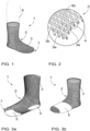
- Figure 1 is a schematic view of a sock 1 for patient use.
- Patient use may comprise the use of the sock by a patient at home care, hospital care, or care at another similar facility. Usage situations may vary, comprising bed rest, sitting, and/or moving of the patient either alone or aided. Obviously, the sock now disclosed is suitable for other purposes as well and is not restricted to the above usage situations.
- the sock 1 for patient used comprises a tubular mesh structure 2, such as a mesh structure 2 of the type shown schematically in Figure 2 .
- the mesh structure 2 is breathable due to its very structure and consequently it is not sweaty.
- the mesh structure 2 is flexible at least in its transverse direction, that is, in the direction transverse in relation to the longitudinal direction of the tube.
- the mesh structure is adaptable in a fitting way, forming to the shapes of a foot but not compressing them, for feet of different sizes and is suitable, for example, to be simultaneously used with patient clothes or means of treatment of various kinds.
- the mesh structure 2 may be formed to be flexible in its longitudinal direction, too.
- the mesh structure 2 comprises monofilaments 3.
- the mesh structure 2 is formed of single-fibre, yarn-like parts.
- the monofilaments 3 may be monolithic, that is, single-element ones.
- the monofilaments 3 in this case do not comprise a plurality of intertwined fibres of possibly different materials, or nested or adjacent layers of materials, but consists of one fibre that is of the same uniform material through the entire cross section of the monofilament.
- the monofilament 3 shown in Figure 2 has a round cross section, but in different embodiments the cross section of the monofilament 3 may also be oblong, square, polygon, or of another appropriate form.
- Figures 4a-4e show cross sections of monofilaments 3.
- Figure 4a shows a monofilament 3a of the first layer and 3b of the second layer, substantially round as to their cross section.
- Figure 4b shows a monofilament 3a of the first layer and 3b of the second layer, substantially triangular as to their cross section.
- the cross section of the monofilament 3 may be chosen such that is directs a massaging effect on a foot.
- the monofilament 3 may be adapted tubular by arranging a channel 11 inside it, as in the embodiments of Figures 4c and 4d .
- the monofilament 3 may be hollow on the inside.
- the cross section of the filament in Figure 4d is substantially round, it is obvious for a person skilled in the art that the cross section of the monofilament may also vary in embodiments in which a channel 11 is arranged within the monofilament.
- mesh structure 2 may comprise fibre mass.
- the fibre mass may comprise a material in which fibres have been mixed with or into the monolithic material.
- Fibre mass in this case does not refer to a fibre filament in which fibres have been twisted or twined to each other or, for example, adapted into substantially parallel fibre bundles, but material in which cut fibres are mixed into the rest of the material mixture.
- Embodiments comprising fibre mass are suited to usages where it is necessary to strengthen the mesh structure against, for example, incisions by the means of treatment or other external pieces, and in which the mesh structure as such allows an adequate degree of flexibility.
- other material may have been adapted than the material of the monofilament.
- fibre mass for example, may be adapted.
- the fibre mass may have been mixed into the monolithic material.
- coated fibres, or fibres adapted inside a second monolithic material may have been adapted, as in Figure 4d . Even in such a case, it is advantageous that it is specifically the monofilaments 3a of the first layer and the monofilaments 3b of the second layer of the mesh structure 2 that are welded together on the surfaces facing each other at intersecting points 4. In other words, fibres or fibre mass possibly adapted inside the monofilament 3 form a filler and do not extend to the welding.
- the monofilaments 3 are adapted in at least two layers so that the monofilaments 3 of each layer are adapted mutually substantially parallel and crosswise 3 in relation to the monofilament of the subsequent layer.
- the mesh structure 2 comprises a plurality of mutually substantially parallel first-layer monofilaments 3a adapted in the first layer, and a plurality of mutually substantially parallel second-layer monofilaments 3b adapted in the second layer.
- Each monofilament 3a of the first layer is adapted in each particular case to intersect at least one second-layer monofilament 3b.
- the intersecting points of the monofilaments 3, 3a, 3b of two different layers form intersecting points 4.
- Each monofilament 3, 3a, 3b intersects the monofilament of the subsequent layer in at least one intersecting point 4. Outside the intersecting points 4 both the monofilaments of the same layer and different layers may advantageously move in relation to each other, advantageously in a substantially free manner.
- the monofilament 3, 3a, 3b may advantageously be welded to the intersecting monofilament in the subsequent layer.
- the monofilament 3a of the first layer may, in the areas on the side of the second layer, be solidly welded together to an area of the monofilament 3b on the side of the first layer at the intersecting point 4.
- the surfaces of at least monofilaments 3a, 3b are in such a case fused together in the intersecting area of the monofilaments 3a, 3b, facing each other,
- the welding may advantageously be achieved by forming the mesh structure 2 by an extrusion method by means of two nozzles adapted one inside the other and rotating in opposite directions, whereby each nozzle forms the monofilaments of one layer in each particular case.
- the mesh structure 2 may be established at one work stage without specific moulds or similar special tools, except for the nozzles, which speeds up and simplifies the manufacturing process. At the same time, coating and other work stages related to coatings and similar manufacturing methods may be avoided.
- the sock 1 may be formed entirely as a single element one. In this case, the sock 1 does not comprise any separate material layers or material fibres connected to each other in one way or another, but is formed in its entirety out of the same material. In an embodiment, the sock 1 may be entirely formed as a mesh structure 2 formed by monofilaments. In such a case, the sock 1 does not comprise any separate parts, or parts attached to the sock, differing from the mesh structure 2 as to their structure. In an embodiment, the sock 1 may be entirely formed as a mesh structure 2 formed by single-element monofilaments.
- the monofilament 3 is formed of a material with a high friction coefficient.
- a high friction coefficient means that the monofilament 3 is formed of a material that has a higher friction coefficient in relation to the common floor surface materials, in other words, a higher static coefficient of friction and/or kinetic coefficient than the common sock materials such as cotton, wool, polyamide, acryl, or their combinations, typically formed as knitted fabrics of various kinds.
- the sock 1 may in such a case act as a so-called friction sock, which may prevent a patient from slipping when he is getting onto his feet, is walking alone or aided, or when a patient is lifted.
- the sock 1 acts as an anti-slip device without coating or other post-processing such as dip treatment.
- the socks 1 described in this description are especially usable as friction socks also when used simultaneously with patient clothes and means of treatment of various kinds, because due to their formability they are easy to fit in feet of different sizes and, for example, over conventional patient socks or even over treatment means.
- the mesh structure 2 may comprise thermoplastic elastomer, such as polypropylene-based thermoplastic elastomer.
- the mesh structure 2 may comprise synthetic rubber material such as styrene butadiene rubber (SBR).
- the mesh structure 2 may comprise monofilaments 3 comprising different two materials so that the first-layer monofilaments 3a may comprise a different material than the second-layer monofilaments 3b.
- the monofilaments 3 of the layer against the foot in the usage position such as first-layer monofilaments 3a, may comprise a material whose friction coefficient is lower than that of the material that the second-layer monofilaments 3b comprise. In this manner, it is possible to form a sock 1 that is easy to put on the foot and which at the same time creates an efficient anti-slip effect between the foot and base.
- Such as mesh structure 2 may advantageously be formed by the extrusion method by means of two nozzles adapted one inside the other and rotating in opposite directions, whereby each nozzle forms the monofilaments of one layer at any one time and whereby the material fed to the first nozzle 8a differs from the material fed to the second nozzle 8b.
- the first-layer monofilaments 3a may comprise, for example, polypropylene and the second-layer monofilaments 3b may comprise, for example, polypropylene filled with EPDM rubber (Ethylene Propylene Diene Monomer rubber).
- the inner layer may be formed of slippery and thus easy to put on and well moisture-transferring polypropylene, and the outer surface of a material that has a higher friction coefficient, and which may, however, due to the same base material may be easily adapted to weld to each other.
- structures welding to each other comprise one or more monolithic material that have the same base substance.
- the welding structures may in such a case comprise the same material or alternatively materials that differ from each other, but which, however, advantageously have the same matrix whereby they weld together but may nevertheless achieve different properties on different surfaces.
- the mesh structure 2 may comprise two monofilaments 3a, 3b having different cross sections so that the first-layer monofilaments 3a may comprise a cross section of a different shape than the second-layer monofilaments 3b.
- the monofilaments 3 of the layer against the foot in the usage position such as first-layer monofilaments 3a, may comprise a cross section whose friction coefficient is lower than the cross section that the second-layer monofilaments 3b comprise.
- Figure 4e An example of such an embodiment is shown in Figure 4e .
- the shape of the surface of the first-layer monofilaments 3a towards the foot in the usage position may be formed smooth and/or narrow, such as rounded.
- the shape of the surface of the second-layer monofilaments 3b towards the base in the usage position may be formed to add to the friction and/or friction surface, such as grooved and/or wider than the surface of the first-layer monofilaments 3a, directed towards the foot.
- Such as mesh structure 2 may advantageously be formed by the extrusion method by means of two nozzles adapted one inside the other and rotating in opposite directions, whereby each nozzle forms the monofilaments of one layer at any one time and whereby the cross section of openings 10 formed in the first nozzle 8a differs from the cross section of openings 10 formed in the second nozzle 8b.
- the sock 1 may comprise silver ions to establish an anti-bacteria effect. So, in this case the sock 1 may be formed anti-bacterial. This is beneficial in connection with wounds and ulcers of various kinds and in hospital and similar facility environments, in particular.
- the sock 1 may also be formed as one removing body odour.
- the tubular mesh structure 2 is formed to be closed at one end so that the sock forms a bag-like mesh structure.
- a sock 1 may be formed, for example, by forming a tubular mesh structure 2 by the extrusion method with two nozzles adapted one inside the other and rotating in opposite directions, and by closing one end of the tubular mesh structure 2 by melting or welding, for example.
- Figures 3a and 3b are schematic views of socks 1 for patient use.
- the sock 1 may comprise at least one slide block 5.
- the slide block 5 is formed of a material having a friction coefficient lower than the friction coefficient of the mesh structure 2.
- the sock 1 may be formed on a chosen area, that is, in the area of the slide block 5, to be better sliding than elsewhere in the area of the sock 1, such as the area of the mesh structure 2.
- the slide block 5 may comprise a film-like or mesh-like piece.
- one slide block 5 or a plurality of slides 5 may be fixedly adapted in the mesh structure 2 by welding.
- one slide block 5 or a plurality of slides 5 may be adapted in the mesh structure 2 by seaming.
- one slide block 5 or a plurality of slides 5 may be adapted in the mesh structure 2 by laminating.
- at least one slide block 5 may be adapted in the mesh structure immovably and non-detachably by, for example, welding, seaming, or laminating.
- At least one slide block 5 may be adapted in the sock 1 so that the slide block 5 places itself under the front part of the foot when the sock 1 has been put on a leg 6.
- the mesh structure 2 may be formed closed at one of its ends, and the slide block 5 in such a case may be adapted in the mesh structure 2 closer to the closed end 7 of the mesh structure 2 than its open end, whereby the slide block 5 places itself under the front part of the foot when the sock has been put on the leg 6.
- At least one slide block 5 may be adapted in the sock 1 so that it extends substantially around the sock, advantageously in the area that places itself under the front part of the foot when the sock 1 has been put on the leg 6, such as in the embodiment of Figure 3b .
- the advantage of such a sock 1 is that it does not matter which way or in which position the sock is put on the leg.
- the sock 1 comprises two slides 5.
- the sock 1 may comprise, as stated in the above, just one slide block 5, such as the slide block 5 of Figure 3a , arranged on the left, so in connection with the closed end of the sock 1, in other words under the front part of the foot.
- a second slide block 5 may be adaptable to be placed under the heel according to Figure 3a .
- the slide block arranged under the heel may, for example, in an embodiment comprise material that has a higher friction coefficient that the slide block 5 adaptable under the front part of the foot.
- the sock 1 comprises a separate flexible cuff.
- the flexible cuff may be formed of the same material as the mesh structure 2 or of a different material. Such a flexible cuff may facilitate putting on the sock 1 and helps the sock stay on the leg.
- the flexible cuff may be fixedly adapted in the open end of the mesh structure by welding, for example.
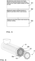
- FIG 5 is a schematic representation of a method for making a sock 1 for patient use, such as any of the socks 1 disclosed in this description.
- a sock 1 may be manufacturing 51 the mesh structure 2 out of single-element raw material granulates by the extrusion method.
- the mesh structure 2 may be made by two nozzles 8a, 8b arranged one within the other, such as by the nozzle arrangement 9 schematically shown in Figure 5a or 5b, comprising such nozzles 8a, 8b.
- the nozzles 8a, 8b may be adapted rotatable in relation to each other.
- the nozzles 8a, 8b may be adapted to rotate in opposite directions so that, for example, the inner nozzle 8a rotates clockwise and the outer nozzle 8b rotates anticlockwise, such as in Figure 6 , which is a schematic view of a nozzle arrangement, or correspondingly so that the inner nozzle 8a rotates anticlockwise and the outer nozzle 8b rotates clockwise.
- openings 10 for the extrusion material may have been formed circumferentially at a distance from each other.
- the nozzles 8a, 8b may, in other words, be rotated 52 in opposite directions in relation to each other to form the tubular mesh structure 2.
- extrusion material may be led through the openings 10 as the nozzles 8a, 8b are rotated in opposite directions in relation to each other to form the tubular mesh structure 2.
- a bag-like sock, closed at one end, is formed 53 by closing one end of the tubular mesh structure by melting or welding, for example.
- the mesh structure 2 may be formed by any of the methods disclosed in this description, whereby the mesh structure may be used for other purposes than to make a sock intended for patient use.
- the method may further comprise features and process steps described in connection with the embodiments 2 and socks 1, such as the use of different materials and openings 10, adapting at least one slide block 5 in the mesh structure 2 and/or sock 1, and so forth.
- a method of any of the described embodiments may be used.
- Ordinary patient socks are typically knit tubes, sewn closed at an end, which have the tendency to slip and stay badly in place.
- the sock according to the solution now put forth may, for example, be adapted over such a patient sock, in which case it keeps the patient sock firmly in place without compressing, and on the other hand acts as an anti-slip device as the patient is moving alone or aided. Because the sock now put forth does not compress the foot, it is suitable for use on feet that hurt and/or are swollen.
- the sock may be easily modified according to patient-specific needs by, for example, cutting the mesh structure open where needed, such as at a wound or a swelling, or to adapt means of treatment to pass through the sock.
- a sock according so some of the embodiments disclosed in this description may also be washed, allowing it to be used for a number of times, in other words it is not for a single use, only. This reduces the amount of garbage produced.
- the mesh structure 2 and sock 1 now described are particularly well suited for patient use, it is obvious for a person skilled in the art that the mesh structure 2 and sock 1 may also be used for other purposes where a tubular mesh structure flexible at least in the transverse direction and cost-effective to manufacture is needed.
- the embodiments provided with the friction characteristics may be used, in addition to patient use, by elderly people and, for example, in bathroom, swimming hall, or spa conditions to prevent slipping.
Landscapes
- Engineering & Computer Science (AREA)
- Textile Engineering (AREA)
- Health & Medical Sciences (AREA)
- Mechanical Engineering (AREA)
- General Health & Medical Sciences (AREA)
- Biomedical Technology (AREA)
- Heart & Thoracic Surgery (AREA)
- Vascular Medicine (AREA)
- Life Sciences & Earth Sciences (AREA)
- Animal Behavior & Ethology (AREA)
- Public Health (AREA)
- Veterinary Medicine (AREA)
- Physical Education & Sports Medicine (AREA)
- Socks And Pantyhose (AREA)
Claims (5)
- Socke zur Patientenverwendung, wobei die Socke Folgendes umfasst:
eine rohrförmige Maschenstruktur, die zumindest in ihrer Querrichtung derart biegsam ist, dass ein Fuß des Patienten nicht zusammengedrückt wird, wobei die rohrförmige Maschenstruktur Folgendes umfasst:Einzelelement-Monofilamente, die derart in mindestens zwei Schichten angepasst sind, dass die Monofilamente von jeder Schicht gegenseitig im Wesentlichen parallel und kreuzweise in Bezug auf das Monofilament der anschließenden Schicht angepasst sind, und jedes Monofilament sich an jedem Schnittpunkt befindet, wo das Monofilament das Monofilament der anschließenden Schicht schneidet, das an das schneidende Monofilament der anschließenden Schicht geschweißt ist,wobei das Monofilament aus einem Material mit einem hohen Reibungskoeffizienten gebildet ist, wobei der hohe Reibungskoeffizient bedeutet, dass das Monofilament aus einem Material gebildet ist, das im Verhältnis zu den üblichen Bodenoberflächenmaterialien einen höheren Reibungskoeffizienten, mit anderen Worten einen höheren statischen Reibungskoeffizienten und/oder kinetischen Koeffizienten, als die üblichen Sockenmaterialien, wie beispielsweise Baumwolle, Wolle, Polyamid, Acryl oder ihre Kombinationen, die typischerweise als gestrickte Gewebe verschiedener Arten gebildet sind, aufweist, unddie rohrförmige Maschenstruktur gebildet ist, um an einem Ende durch Schließen der rohrförmigen Maschenstruktur an einem Ende durch Schmelzen oder Schweißen geschlossen zu werden, derart dass die Socke eine taschenartige Maschenstruktur bildet,wobei das Material mit einem hohen Reibungskoeffizienten Synthesekautschukmaterial und/oder thermoplastisches Elastomer umfasst, undwobei die Socke vollständig aus einer Maschenstruktur gebildet ist, die aus den Einzelelement-Monofilamenten gebildet ist, oderdie Socke ferner einen Gleitblock umfasst, der aus einem Material gebildet ist, das einen niedrigeren Reibungskoeffizienten als der Reibungskoeffizient der Maschenstruktur besitzt und durch Schweißen fest an die Maschenstruktur angepasst ist. - Socke nach Anspruch 1, wobei das Synthesekautschukmaterial Styrol-Butadien-Kautschuk umfasst.
- Socke nach Anspruch 1 oder 2, die Silberionen umfasst, um eine antibakterielle Wirkung herzustellen.
- Socke nach einem der Ansprüche 1 bis 3, die ferner einen separaten Bund umfasst, der durch Schweißen fest an das offene Ende der Maschenstruktur angepasst ist.
- Verfahren zur Herstellung einer Socke zur Patientenverwendung, wobei in dem Verfahren eine Socke nach einem der Ansprüche 1 bis 4 durch Herstellen einer rohrförmigen Maschenstruktur aus Einzelelement-Rohmaterialgranulaten durch das Extrusionsverfahren durch zwei Düsen, die ineinander drehbar angepasst sind, wobei beide ihrer Öffnungen für das Extrusionsmaterial derart in Umfangsrichtung in einem Abstand voneinander angepasst wurden, dass die Düsen in zueinander entgegengesetzten Richtungen gedreht werden, um die rohrförmige Maschenstruktur zu bilden, und Schließen des anderen Endes der rohrförmigen Maschenstruktur durch Schmelzen oder Schweißen hergestellt wird.
Applications Claiming Priority (1)
| Application Number | Priority Date | Filing Date | Title |
|---|---|---|---|
| FI20175379A FI128191B (fi) | 2017-04-28 | 2017-04-28 | Sukka potilaskäyttöä varten ja menetelmä sukan valmistamiseksi |
Publications (3)
| Publication Number | Publication Date |
|---|---|
| EP3412263A1 EP3412263A1 (de) | 2018-12-12 |
| EP3412263C0 EP3412263C0 (de) | 2023-06-07 |
| EP3412263B1 true EP3412263B1 (de) | 2023-06-07 |
Family
ID=62630890
Family Applications (1)
| Application Number | Title | Priority Date | Filing Date |
|---|---|---|---|
| EP18169402.7A Active EP3412263B1 (de) | 2017-04-28 | 2018-04-26 | Socke zur patientenverwendung und verfahren zur herstellung einer socke |
Country Status (2)
| Country | Link |
|---|---|
| EP (1) | EP3412263B1 (de) |
| FI (1) | FI128191B (de) |
Families Citing this family (1)
| Publication number | Priority date | Publication date | Assignee | Title |
|---|---|---|---|---|
| WO2022195135A1 (es) * | 2021-03-16 | 2022-09-22 | Pastor Y Navarro, S.L. | Ropa interior para muñecas sin costuras y en pieza única y procedimiento de confección de dicha ropa |
Citations (1)
| Publication number | Priority date | Publication date | Assignee | Title |
|---|---|---|---|---|
| US3423377A (en) * | 1966-05-06 | 1969-01-21 | Gen Motors Corp | Low friction elastomers |
Family Cites Families (4)
| Publication number | Priority date | Publication date | Assignee | Title |
|---|---|---|---|---|
| US2919467A (en) * | 1955-11-09 | 1960-01-05 | Plastic Textile Access Ltd | Production of net-like structures |
| DE1215912B (de) * | 1960-11-25 | 1966-05-05 | Du Pont | Vorrichtung zum Strangpressen eines aus thermoplastischem Kunststoff bestehenden Netzgebildes |
| FR2204730A1 (en) * | 1972-10-31 | 1974-05-24 | Fontanille Fils Sa | Extrusion die for making non woven fabric - with programmable motions for generating different structures |
| FR2521065A1 (fr) * | 1982-02-10 | 1983-08-12 | Nortene Sa | Structure reticulaire en matiere plastique, utilisable notamment pour la realisation de grillages et de poches d'elevage ostreicole, son procede de fabrication et dispositif pour sa mise en oeuvre |
-
2017
- 2017-04-28 FI FI20175379A patent/FI128191B/fi active IP Right Grant
-
2018
- 2018-04-26 EP EP18169402.7A patent/EP3412263B1/de active Active
Patent Citations (1)
| Publication number | Priority date | Publication date | Assignee | Title |
|---|---|---|---|---|
| US3423377A (en) * | 1966-05-06 | 1969-01-21 | Gen Motors Corp | Low friction elastomers |
Also Published As
| Publication number | Publication date |
|---|---|
| EP3412263C0 (de) | 2023-06-07 |
| FI128191B (fi) | 2019-12-13 |
| FI20175379A1 (fi) | 2018-10-29 |
| EP3412263A1 (de) | 2018-12-12 |
Similar Documents
| Publication | Publication Date | Title |
|---|---|---|
| KR101061895B1 (ko) | 은사 메쉬 및 이를 이용한 항균마스크 | |
| US7012169B2 (en) | Disposable finger sleeve for appendages | |
| CN106604703B (zh) | 具有高效制造和在美学上令人愉悦的后腿部边缘轮廓的裤结构 | |
| DE102013207153B4 (de) | An die Fußform angepasster Schuh | |
| DE202010017758U1 (de) | Gepolsterte saugfähige Matte | |
| EP3733941B1 (de) | Kompressives gestrickteil mit haftwirkung | |
| US12202244B2 (en) | Article of apparel | |
| KR101234417B1 (ko) | 신장성 및 투과성 부직포 보호 장갑 | |
| KR100875709B1 (ko) | 열가소성 폴리우레탄 코팅 원사를 이용한 논슬립성 원단 | |
| DE102013207155A1 (de) | Schuhoberteil | |
| EP3412263B1 (de) | Socke zur patientenverwendung und verfahren zur herstellung einer socke | |
| CN103813728A (zh) | 无缝防护外衣 | |
| US10485289B2 (en) | Safety slipper | |
| EP2763561B1 (de) | Verbundstoff mit verbesserter feuchtigkeitsableitung | |
| EP2629724B1 (de) | Bandage zum anlegen an einen menschlichen oder tierischen körper | |
| EP4355279A1 (de) | Verband zum umschliessen eines bein- oder armbereiches eines lebewesens | |
| JP6302898B2 (ja) | 多種の層および帯域を備えていている伸縮性シートおよび当該製品を生産する方法 | |
| EP3295911A1 (de) | Neuartige wiederverwendbare schwimmwindel | |
| EP2202436A3 (de) | Flexibler Schlauch | |
| US20140206249A1 (en) | Elastomer-enhanced fabrics, articles of manufacture including such fabrics, and methods of making same | |
| KR100849935B1 (ko) | 천공된 폴리우레탄 코팅이 적층된 메쉬 원단을 포함하는카시트 커버 및 그 제조 방법 | |
| DE102020119662A1 (de) | Gepolsterte Matte, insbesondere Badematte | |
| JP2001164407A (ja) | 編靴下 | |
| WO2016045985A1 (de) | Textil mit haftwirkung | |
| EP2699415B1 (de) | Flächenförmiges verbundelement |
Legal Events
| Date | Code | Title | Description |
|---|---|---|---|
| PUAI | Public reference made under article 153(3) epc to a published international application that has entered the european phase |
Free format text: ORIGINAL CODE: 0009012 |
|
| STAA | Information on the status of an ep patent application or granted ep patent |
Free format text: STATUS: THE APPLICATION HAS BEEN PUBLISHED |
|
| AK | Designated contracting states |
Kind code of ref document: A1 Designated state(s): AL AT BE BG CH CY CZ DE DK EE ES FI FR GB GR HR HU IE IS IT LI LT LU LV MC MK MT NL NO PL PT RO RS SE SI SK SM TR |
|
| AX | Request for extension of the european patent |
Extension state: BA ME |
|
| STAA | Information on the status of an ep patent application or granted ep patent |
Free format text: STATUS: REQUEST FOR EXAMINATION WAS MADE |
|
| 17P | Request for examination filed |
Effective date: 20190612 |
|
| RBV | Designated contracting states (corrected) |
Designated state(s): AL AT BE BG CH CY CZ DE DK EE ES FI FR GB GR HR HU IE IS IT LI LT LU LV MC MK MT NL NO PL PT RO RS SE SI SK SM TR |
|
| STAA | Information on the status of an ep patent application or granted ep patent |
Free format text: STATUS: EXAMINATION IS IN PROGRESS |
|
| 17Q | First examination report despatched |
Effective date: 20191107 |
|
| RIC1 | Information provided on ipc code assigned before grant |
Ipc: D04H 3/16 20060101ALI20220915BHEP Ipc: D04H 3/04 20120101ALI20220915BHEP Ipc: D04H 3/073 20120101ALI20220915BHEP Ipc: B29C 48/13 20190101ALI20220915BHEP Ipc: B29D 28/00 20060101ALI20220915BHEP Ipc: A61F 13/08 20060101AFI20220915BHEP |
|
| GRAP | Despatch of communication of intention to grant a patent |
Free format text: ORIGINAL CODE: EPIDOSNIGR1 |
|
| STAA | Information on the status of an ep patent application or granted ep patent |
Free format text: STATUS: GRANT OF PATENT IS INTENDED |
|
| INTG | Intention to grant announced |
Effective date: 20221025 |
|
| GRAS | Grant fee paid |
Free format text: ORIGINAL CODE: EPIDOSNIGR3 |
|
| RAP3 | Party data changed (applicant data changed or rights of an application transferred) |
Owner name: CARECARE OY |
|
| RAP3 | Party data changed (applicant data changed or rights of an application transferred) |
Owner name: CARECARE OY |
|
| GRAA | (expected) grant |
Free format text: ORIGINAL CODE: 0009210 |
|
| STAA | Information on the status of an ep patent application or granted ep patent |
Free format text: STATUS: THE PATENT HAS BEEN GRANTED |
|
| AK | Designated contracting states |
Kind code of ref document: B1 Designated state(s): AL AT BE BG CH CY CZ DE DK EE ES FI FR GB GR HR HU IE IS IT LI LT LU LV MC MK MT NL NO PL PT RO RS SE SI SK SM TR |
|
| REG | Reference to a national code |
Ref country code: GB Ref legal event code: FG4D |
|
| REG | Reference to a national code |
Ref country code: CH Ref legal event code: EP Ref country code: AT Ref legal event code: REF Ref document number: 1572655 Country of ref document: AT Kind code of ref document: T Effective date: 20230615 |
|
| REG | Reference to a national code |
Ref country code: DE Ref legal event code: R096 Ref document number: 602018050696 Country of ref document: DE |
|
| REG | Reference to a national code |
Ref country code: NO Ref legal event code: T2 Effective date: 20230607 |
|
| U01 | Request for unitary effect filed |
Effective date: 20230620 |
|
| U07 | Unitary effect registered |
Designated state(s): AT BE BG DE DK EE FI FR IT LT LU LV MT NL PT SE SI Effective date: 20230627 |
|
| REG | Reference to a national code |
Ref country code: LT Ref legal event code: MG9D |
|
| PG25 | Lapsed in a contracting state [announced via postgrant information from national office to epo] |
Ref country code: ES Free format text: LAPSE BECAUSE OF FAILURE TO SUBMIT A TRANSLATION OF THE DESCRIPTION OR TO PAY THE FEE WITHIN THE PRESCRIBED TIME-LIMIT Effective date: 20230607 |
|
| PG25 | Lapsed in a contracting state [announced via postgrant information from national office to epo] |
Ref country code: RS Free format text: LAPSE BECAUSE OF FAILURE TO SUBMIT A TRANSLATION OF THE DESCRIPTION OR TO PAY THE FEE WITHIN THE PRESCRIBED TIME-LIMIT Effective date: 20230607 Ref country code: HR Free format text: LAPSE BECAUSE OF FAILURE TO SUBMIT A TRANSLATION OF THE DESCRIPTION OR TO PAY THE FEE WITHIN THE PRESCRIBED TIME-LIMIT Effective date: 20230607 Ref country code: GR Free format text: LAPSE BECAUSE OF FAILURE TO SUBMIT A TRANSLATION OF THE DESCRIPTION OR TO PAY THE FEE WITHIN THE PRESCRIBED TIME-LIMIT Effective date: 20230908 |
|
| PG25 | Lapsed in a contracting state [announced via postgrant information from national office to epo] |
Ref country code: SK Free format text: LAPSE BECAUSE OF FAILURE TO SUBMIT A TRANSLATION OF THE DESCRIPTION OR TO PAY THE FEE WITHIN THE PRESCRIBED TIME-LIMIT Effective date: 20230607 |
|
| PG25 | Lapsed in a contracting state [announced via postgrant information from national office to epo] |
Ref country code: IS Free format text: LAPSE BECAUSE OF FAILURE TO SUBMIT A TRANSLATION OF THE DESCRIPTION OR TO PAY THE FEE WITHIN THE PRESCRIBED TIME-LIMIT Effective date: 20231007 |
|
| PG25 | Lapsed in a contracting state [announced via postgrant information from national office to epo] |
Ref country code: SM Free format text: LAPSE BECAUSE OF FAILURE TO SUBMIT A TRANSLATION OF THE DESCRIPTION OR TO PAY THE FEE WITHIN THE PRESCRIBED TIME-LIMIT Effective date: 20230607 Ref country code: SK Free format text: LAPSE BECAUSE OF FAILURE TO SUBMIT A TRANSLATION OF THE DESCRIPTION OR TO PAY THE FEE WITHIN THE PRESCRIBED TIME-LIMIT Effective date: 20230607 Ref country code: RO Free format text: LAPSE BECAUSE OF FAILURE TO SUBMIT A TRANSLATION OF THE DESCRIPTION OR TO PAY THE FEE WITHIN THE PRESCRIBED TIME-LIMIT Effective date: 20230607 Ref country code: IS Free format text: LAPSE BECAUSE OF FAILURE TO SUBMIT A TRANSLATION OF THE DESCRIPTION OR TO PAY THE FEE WITHIN THE PRESCRIBED TIME-LIMIT Effective date: 20231007 Ref country code: CZ Free format text: LAPSE BECAUSE OF FAILURE TO SUBMIT A TRANSLATION OF THE DESCRIPTION OR TO PAY THE FEE WITHIN THE PRESCRIBED TIME-LIMIT Effective date: 20230607 |
|
| PG25 | Lapsed in a contracting state [announced via postgrant information from national office to epo] |
Ref country code: PL Free format text: LAPSE BECAUSE OF FAILURE TO SUBMIT A TRANSLATION OF THE DESCRIPTION OR TO PAY THE FEE WITHIN THE PRESCRIBED TIME-LIMIT Effective date: 20230607 |
|
| REG | Reference to a national code |
Ref country code: DE Ref legal event code: R097 Ref document number: 602018050696 Country of ref document: DE |
|
| PLBE | No opposition filed within time limit |
Free format text: ORIGINAL CODE: 0009261 |
|
| STAA | Information on the status of an ep patent application or granted ep patent |
Free format text: STATUS: NO OPPOSITION FILED WITHIN TIME LIMIT |
|
| U20 | Renewal fee for the european patent with unitary effect paid |
Year of fee payment: 7 Effective date: 20240327 |
|
| 26N | No opposition filed |
Effective date: 20240308 |
|
| U20 | Renewal fee for the european patent with unitary effect paid |
Year of fee payment: 8 Effective date: 20250325 |
|
| PGFP | Annual fee paid to national office [announced via postgrant information from national office to epo] |
Ref country code: GB Payment date: 20250417 Year of fee payment: 8 |
|
| PGFP | Annual fee paid to national office [announced via postgrant information from national office to epo] |
Ref country code: CH Payment date: 20250501 Year of fee payment: 8 |
|
| PG25 | Lapsed in a contracting state [announced via postgrant information from national office to epo] |
Ref country code: CY Free format text: LAPSE BECAUSE OF FAILURE TO SUBMIT A TRANSLATION OF THE DESCRIPTION OR TO PAY THE FEE WITHIN THE PRESCRIBED TIME-LIMIT; INVALID AB INITIO Effective date: 20180426 |
|
| PG25 | Lapsed in a contracting state [announced via postgrant information from national office to epo] |
Ref country code: HU Free format text: LAPSE BECAUSE OF FAILURE TO SUBMIT A TRANSLATION OF THE DESCRIPTION OR TO PAY THE FEE WITHIN THE PRESCRIBED TIME-LIMIT; INVALID AB INITIO Effective date: 20180426 |
|
| PGFP | Annual fee paid to national office [announced via postgrant information from national office to epo] |
Ref country code: MC Payment date: 20260326 Year of fee payment: 9 |
|
| PGFP | Annual fee paid to national office [announced via postgrant information from national office to epo] |
Ref country code: NO Payment date: 20260330 Year of fee payment: 9 Ref country code: IE Payment date: 20260323 Year of fee payment: 9 |
|
| U20 | Renewal fee for the european patent with unitary effect paid |
Year of fee payment: 9 Effective date: 20260326 |