EP3411631B2 - Cooker hood and power supply arrangement thereof - Google Patents
Cooker hood and power supply arrangement thereof Download PDFInfo
- Publication number
- EP3411631B2 EP3411631B2 EP17704319.7A EP17704319A EP3411631B2 EP 3411631 B2 EP3411631 B2 EP 3411631B2 EP 17704319 A EP17704319 A EP 17704319A EP 3411631 B2 EP3411631 B2 EP 3411631B2
- Authority
- EP
- European Patent Office
- Prior art keywords
- cooker hood
- control unit
- motor
- power supply
- element driver
- Prior art date
- Legal status (The legal status is an assumption and is not a legal conclusion. Google has not performed a legal analysis and makes no representation as to the accuracy of the status listed.)
- Active
Links
- 238000009423 ventilation Methods 0.000 description 7
- 238000000605 extraction Methods 0.000 description 4
- 238000004140 cleaning Methods 0.000 description 3
- 238000004519 manufacturing process Methods 0.000 description 3
- 238000005286 illumination Methods 0.000 description 2
- 230000001747 exhibiting effect Effects 0.000 description 1
- 239000004519 grease Substances 0.000 description 1
- 229910052736 halogen Inorganic materials 0.000 description 1
- 150000002367 halogens Chemical class 0.000 description 1
- 238000009434 installation Methods 0.000 description 1
- 230000003071 parasitic effect Effects 0.000 description 1
- XLYOFNOQVPJJNP-UHFFFAOYSA-N water Substances O XLYOFNOQVPJJNP-UHFFFAOYSA-N 0.000 description 1
Images

Classifications
-
- F—MECHANICAL ENGINEERING; LIGHTING; HEATING; WEAPONS; BLASTING
- F24—HEATING; RANGES; VENTILATING
- F24C—DOMESTIC STOVES OR RANGES ; DETAILS OF DOMESTIC STOVES OR RANGES, OF GENERAL APPLICATION
- F24C15/00—Details
- F24C15/20—Removing cooking fumes
- F24C15/2064—Removing cooking fumes illumination for cooking hood
-
- F—MECHANICAL ENGINEERING; LIGHTING; HEATING; WEAPONS; BLASTING
- F24—HEATING; RANGES; VENTILATING
- F24C—DOMESTIC STOVES OR RANGES ; DETAILS OF DOMESTIC STOVES OR RANGES, OF GENERAL APPLICATION
- F24C15/00—Details
- F24C15/20—Removing cooking fumes
- F24C15/2021—Arrangement or mounting of control or safety systems
Definitions
- the present invention relates to a cooker hood or a kitchen extraction exhaust unit and a power supply arrangement thereof.
- the ventilation unit for installation in a ventilation system.
- the ventilation unit can include a motor coupled to a fan element and a power source.
- the ventilation unit can also include a calibration module having one of a voltage and current regulator for adjusting the performance of the ventilation unit based on at least one characteristic of the ventilation system.
- An AC mains supply is converted in a DC voltage and supplied to a DC motor via a controller.
- WO2006/092219 discloses a ventilation appliance embodied as an exhauster hood.
- a drive is present for generating an air flow, as well as an illumination device.
- a control unit controls the drive and the illumination device using galvanic separated pulse width modulated signals.
- a vapor cleaning apparatus for a range hood which generates high temperature vapor to melt dirty grease on both an exhaust fan and a fan housing.
- the apparatus has a control module which is electrically connected to a vapor cleaning module, an input module and a fan driver module. Also provided is a lighting unit power supply for powering lighting elements.
- the control module executes the vapor cleaning mode, the heater heats the water into vapor and activates the fan driver module to drive a fan motor to blow the vapor to the fan housing.
- DE 10 2005 010 984 A1 discloses a cooker hood having a motor driver and light driver connected to a controller through galvanic separating elements.
- the present invention seeks to provide an improved cooker hood or kitchen extraction exhaust unit, in particular a power supply arrangement thereof, wherein the cooker hood comprises less electronic components and exhibits reduced electrical circuit complexity.
- a cooker hood according to the type defined in the preamble above is provided, wherein the cooker hood comprises a mains supply, one or more lighting elements, and a lighting element driver connected to the mains supply and the one or more lighting elements, and an electronically commuted motor driving a fan, characterized in that a power supply terminal of the EC motor is directly connected to the mains supply and a control terminal of the EC motor is connected to a control unit, wherein the control unit is connected to a power supply output of the lighting element driver.
- the cooker hood of the present invention exhibits reduced circuit complexity as the lightning element driver powers the control unit allowing the EC motor to be controlled and operated by the control unit, such as changing motor speed and hence fan speed of the cooker hood. Consequently, the cooker hood of the present invention does not require centralized power and control signal distribution in the form of a printed circuit board (PCB), sometimes referred to as a "power board". More specifically, in addition to the one or more lighting elements, the present invention allows the lighting element driver to be used for powering the control unit for controlling the EC motor, so that electrical circuit complexity of the cooker hood is significantly reduced as no separate feed is needed to power the control unit. In a practical embodiment the power supply output of the lighting element driver is an auxiliary power supply output for powering the control unit.
- PCB printed circuit board
- control unit is integrated with a user interface of the cooker hood, which further simplifies circuit complexity of the cooker hood. Electric power for the control unit and user interface need not be directly accessed from the mains supply terminal but can be extracted from the lighting element driver, where the control unit for operating the EC motor is readily operated through the user interface on the cooker hood.
- the one or more lighting elements are LED lighting elements
- the lighting element driver is a LED power supply or LED driver.
- the LED power supply may be a dimmable LED power supply.
- control unit is connected to the lighting element driver to control operating parameters of the lighting elements, so that a combined control of both the lighting and the EC motor is possible, circumventing the use of a further control unit for merely controlling the one or more lighting elements.
- Prior art cooker hoods or kitchen extraction exhaust units typically comprise an electric motor for driving a (suction) fan.
- the cooker hood may be operated by a user through e.g. a touch and/or mechanical interface on the cooker hood to operate one or more light elements and/or the fan.
- a centralized power and control signal distribution unit is provided, sometimes called a "power board” in the form of a main printed circuit board (PCB).
- FIG. 1 shows an embodiment of a prior art power supply arrangement for a cooker hood.
- a cooker hood typically comprises a power supply arrangement having an AC power supply terminal 26 connected to a power board (PWRB) 20 or main printed circuit board.
- the power board 20 is connected to a user interface (U/I) 24, a lighting element driver (LED DR) 22, and an electric motor (MTR) 21.
- the lighting element driver 22 is connected to one or more lighting elements such as one or more LED lamps 23.
- a main filter (MF) 25 is provided in the AC line from AC power supply terminal 26 to the power board 20.
- the power board 20 is a central component of the power supply arrangement for a cooker hood from which power and control signals are distributed. Apart from the electric motor 21, the power board 20 is the most complex and expensive component of a cooker hood, and the power board 20 is also a relatively vulnerable component that is relatively expensive to repair. Furthermore, because the power board 20 distributes all power and control signals of the cooker hood, in case of a significant failure the entire cooker hood may become non-functional, e.g. both lighting elements and the electric motor may cease to be operational.
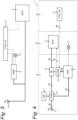
- Figure 2 shows an embodiment, which is not part of the present invention, of a power supply arrangement for a cooker hood.
- Figure 3 shows an embodiment of a power supply arrangement for a cooker hood according to the present invention.
- the cooker hood comprises a mains supply terminal 6, or mains supply 6 for short, one or more lighting elements 3, and a lighting element driver (PWR) 4 connected to the mains supply terminal 6 and the one or more lighting elements 3.
- the cooker hood further comprises an electrical motor 2, in particular a brushless DC motor (or electronically commutated (EC) motor) 2 for driving a fan or having an integrated fan (not shown).
- EC electronically commutated
- a power supply terminal of the EC motor 2 is directly connected to the mains supply terminal 6, and a control terminal of the EC motor 2 is connected to a control unit (CTRL/UI) 5, wherein the control unit 5 is connected to a power supply output of the lighting element driver 4.
- CTRL/UI control unit
- the cooker hood of the present invention efficiently and cleverly utilizes the lighting element driver 4 to power the control unit 5, which in turn is capable of supplying and/or receiving signals to/from the EC motor 2 for controlling operation thereof, e.g. changing speed.
- the use of a power board 20 as depicted in Figure 1 is circumvented as the lighting element driver 4 already provides power to the one or more lighting elements 3 and so there is no need to feed the control unit 5 separately from the mains supply terminal 6.
- the power supply output of the lighting element driver 4 is an auxiliary power supply output (e.g. 12 Volt) for powering the control unit 5.
- control unit 5 is integrated with a user interface of the cooker hood, so that the control unit 5 may be conveniently operated through the user interface, wherein the user interface presents to the user control buttons on how to operate the EC motor 2, e.g. changing speed of the fan.
- the user interface may be arranged at an accessible location at a front portion of the cooker hood, typically at a side portion or bottom portion at the front of the cooker hood.
- the one or more lighting elements 3 are LED lighting elements
- the lighting element driver 4 is a LED power supply, thereby reducing power consumption of the cooker hood.
- the control unit 5 can be connected to and cooperate with any lighting element driver 4 required for a particular application.
- control unit 5 is connected to the lighting element driver 4 to control operating parameters of the one or more lighting elements (3), as indicated by the dashed line in the Figure 2 and 3 embodiments.
- the one or more lighting elements 3 can also be operated by the control unit 5. This further reduces electrical circuit complexities and redundancies and eliminates the need for a power board 20 as outlined earlier.
- the cooker hood may further comprise a standby relay 8 connected between the supply terminal of the EC motor 2 and the mains supply terminal 6, wherein a control input of the standby relay 8 is connected to the control unit 5.
- the control unit 5 provides additional control over power delivered to the EC motor 2 and may be arranged for e.g. temporarily connecting and disconnecting the EC motor 2 from the mains supply terminal 6.
- the standby relay 8 may reduce standby and various parasitic losses within the EC motor 2 when in idle mode.
- control unit 5 may therefore be arranged (dashed line) for controlling the standby relay 8 to further reduce electrical circuit complexity of the cooker hood and circumvent the need for a power board 20.
- the cooker hood comprises a mains filter 7 connected between the mains supply terminal 6 and the EC motor 2 and/or the lighting element driver 4.
- the mains filter 7 reduces e.g. noise and various EMI disturbances coming from the power grid into the electrical circuit of the cooker hood and also reduces noise and various EMI disturbances being injected into the power grid coming from the cooker hood.
- control unit 5 allows the EC motor 2 to be controlled, e.g. allowing speed control of the fan.
- the type of control used for the EC motor 2 can be chosen to meet particular requirements and is not limited by the power delivered to the control unit 5 by the lighting element driver 4.
- the control unit 5 is arranged to control an operating speed of the EC motor 2 (dashed line) using an analogue control signal or a pulse width modulated signal, so that it is possible to manufacture cooker hoods for different applications, price and quality ranges etc.
- FIG. 4 shows a schematic embodiment, which is not part of the present invention, of a cooker hood and a power supply arrangement thereof.
- the cooker hood 1 comprises a front portion or housing area 1a that comprises the control unit 5, which may be incorporated with a user interface.
- the cooker hood 1 further comprises an internal space 1b housing the EC motor 2 for driving a fan and the one or more lighting elements 3, such as LED, halogen lamps and the like.
- a top area 1c is provided to the cooker hood which comprises the mains supply terminal 6 and the lighting element driver 4, i.e. in general the electronic circuitry of the cooker hood 1.
- the power supply terminal of the EC motor 2 is directly connected to the mains supply terminal 6.
- a first connector block 11 may be provided for connecting the EC motor 2, as wells as the lighting element driver 4, to the mains supply terminal 6.
- a second connector block 12 is provided to connect the control terminal of the EC motor 2 to the control unit 5, wherein the control unit 5 is connected to the power supply output of the lighting element driver 4 through the second connector block 12.
- the power supply output of the lighting element driver 4 may be an auxiliary power supply output (e.g. 12 Volt) connected to the second connector block 12.
- the second connector bock 12 may be connected to a standby relay 8 for control thereof and a mains filter 7 may be provided connected to the first connector block 11.
- FIG. 4 which is not part of the present invention, it is shown that various cable types may be utilized for connecting the components of the power supply arrangement for the cooker hood 1.
- a 3-wire cable type 3p is provided to connect the EC motor 2 to the mains supply terminal 6, whereas a 2-wire cable type 2p is utilized for connecting the lighting element driver 4 to the mains supply terminal 6.
- the control unit 5/user interface is connected to the lighting element driver 4 and the EC motor 2 through a 6-wire cable 6p connected to the second connector block 12, which is connected to the lighting element driver 4 with a 4-wire cable type 4p.
- the EC motor 2 is connected to the second connector block 12 with a 2-wire cable type 2p.
- FIG. 4 depicts a specific embodiment of the cooker hood 1, which is not part of the present invention, and in particular a power supply arrangement thereof, no centralized power board or PCB is used to separately feed the control unit 5 from the mains supply terminal 6. That is, the control unit 5 is powered by the lighting element driver 4 and there is no need to separately transform electrical power supplied at the mains supply terminal 6, e.g. using a separate inverter, for powering the control unit 5.
- the lighting element driver 4 already provides a suitable voltage and sufficient power for powering the control unit 5 in addition to the one or more lighting elements 3. In this way a complex, expensive and vulnerable power board can be dispensed with and as such electrical circuit complexity of the cooker hood 1 is reduced considerably, as well as manufacturing cost.
- the present invention further relates to a power supply arrangement for a cooker hood or kitchen extraction exhaust unit, wherein the power supply arrangement comprises a mains supply terminal 6, one or more lighting elements 3, a lighting element driver 4 connected to the mains supply terminal 6 and the one or more lighting elements 3.
- the power supply arrangement comprises a mains supply terminal 6, one or more lighting elements 3, a lighting element driver 4 connected to the mains supply terminal 6 and the one or more lighting elements 3.
- an electronically commuted (EC) motor 2 driving a fan wherein a power supply terminal of the EC motor 2 is directly connected to the mains supply terminal 6 and a control terminal of the EC motor 2 is connected to a control unit 5, wherein the control unit 5 is connected to a power supply output of the lighting element driver 4.
- EC electronically commuted
- the power supply arrangement circumvents the use of a power board or PCB for distributing power and/or control signals to/from a control unit 5, an EC motor 2 and a lighting element driver 4.
- the lighting element driver 4 can be utilized to provide power to the control unit 5, which is then able to communicate with the EC motor 2 and/or the one or more lighting elements 3 for control thereof. Electrical connections for power and control signal distribution is then realized with standard electrical cable types.
Description
- The present invention relates to a cooker hood or a kitchen extraction exhaust unit and a power supply arrangement thereof.
- American patent publication
US2012/0052792 discloses a ventilation unit for installation in a ventilation system. The ventilation unit can include a motor coupled to a fan element and a power source. The ventilation unit can also include a calibration module having one of a voltage and current regulator for adjusting the performance of the ventilation unit based on at least one characteristic of the ventilation system. An AC mains supply is converted in a DC voltage and supplied to a DC motor via a controller. - International patent publication
WO2006/092219 discloses a ventilation appliance embodied as an exhauster hood. A drive is present for generating an air flow, as well as an illumination device. A control unit controls the drive and the illumination device using galvanic separated pulse width modulated signals. - American patent publication
US2014/076367 discloses a vapor cleaning apparatus for a range hood which generates high temperature vapor to melt dirty grease on both an exhaust fan and a fan housing. The apparatus has a control module which is electrically connected to a vapor cleaning module, an input module and a fan driver module. Also provided is a lighting unit power supply for powering lighting elements. When the control module executes the vapor cleaning mode, the heater heats the water into vapor and activates the fan driver module to drive a fan motor to blow the vapor to the fan housing. -
DE 10 2005 010 984 A1 discloses a cooker hood having a motor driver and light driver connected to a controller through galvanic separating elements. - The present invention seeks to provide an improved cooker hood or kitchen extraction exhaust unit, in particular a power supply arrangement thereof, wherein the cooker hood comprises less electronic components and exhibits reduced electrical circuit complexity.
- According to the present invention a cooker hood according to the type defined in the preamble above is provided, wherein the cooker hood comprises a mains supply, one or more lighting elements, and a lighting element driver connected to the mains supply and the one or more lighting elements, and an electronically commuted motor driving a fan, characterized in that a power supply terminal of the EC motor is directly connected to the mains supply and a control terminal of the EC motor is connected to a control unit, wherein the control unit is connected to a power supply output of the lighting element driver.
- The cooker hood of the present invention exhibits reduced circuit complexity as the lightning element driver powers the control unit allowing the EC motor to be controlled and operated by the control unit, such as changing motor speed and hence fan speed of the cooker hood. Consequently, the cooker hood of the present invention does not require centralized power and control signal distribution in the form of a printed circuit board (PCB), sometimes referred to as a "power board". More specifically, in addition to the one or more lighting elements, the present invention allows the lighting element driver to be used for powering the control unit for controlling the EC motor, so that electrical circuit complexity of the cooker hood is significantly reduced as no separate feed is needed to power the control unit. In a practical embodiment the power supply output of the lighting element driver is an auxiliary power supply output for powering the control unit.
- In an advantageous embodiment, the control unit is integrated with a user interface of the cooker hood, which further simplifies circuit complexity of the cooker hood. Electric power for the control unit and user interface need not be directly accessed from the mains supply terminal but can be extracted from the lighting element driver, where the control unit for operating the EC motor is readily operated through the user interface on the cooker hood.
- To reduce power consumption of the cooker hood and to provide good lighting conditions under and around the cooker hood, an embodiment is provided wherein the one or more lighting elements are LED lighting elements, and the lighting element driver is a LED power supply or LED driver. In an advantageous embodiment the LED power supply may be a dimmable LED power supply.
- In a further advantageous embodiment, the control unit is connected to the lighting element driver to control operating parameters of the lighting elements, so that a combined control of both the lighting and the EC motor is possible, circumventing the use of a further control unit for merely controlling the one or more lighting elements.
- The present invention will be discussed in more detail below, using a number of exemplary embodiments, with reference to the attached drawings, in which
-
Figure 1 shows an embodiment of a prior art power supply arrangement for a cooker hood; -
Figure 2 shows an embodiment, which is not part of the present invention, of a power supply arrangement utilizing a mains filter and standby relay for a cooker hood; -
Figure 3 shows an embodiment of a power supply arrangement for a cooker hood according to the present invention; and -
Figure 4 shows a schematic embodiment, which is not part of the present invention, of a cooker hood and a power supply arrangement thereof. - Prior art cooker hoods or kitchen extraction exhaust units typically comprise an electric motor for driving a (suction) fan. The cooker hood may be operated by a user through e.g. a touch and/or mechanical interface on the cooker hood to operate one or more light elements and/or the fan. To provide power from a mains supply terminal at the cooker hood to the one or more lighting elements and/or the electric motor, and to distribute control signals for operating the cooker hood, a centralized power and control signal distribution unit is provided, sometimes called a "power board" in the form of a main printed circuit board (PCB).
-
Figure 1 shows an embodiment of a prior art power supply arrangement for a cooker hood. In the prior art embodiment depicted, a cooker hood typically comprises a power supply arrangement having an ACpower supply terminal 26 connected to a power board (PWRB) 20 or main printed circuit board. Thepower board 20 is connected to a user interface (U/I) 24, a lighting element driver (LED DR) 22, and an electric motor (MTR) 21. Thelighting element driver 22 is connected to one or more lighting elements such as one ormore LED lamps 23. Furthermore, a main filter (MF) 25 is provided in the AC line from ACpower supply terminal 26 to thepower board 20. - As can be seen from
Figure 1 , thepower board 20 is a central component of the power supply arrangement for a cooker hood from which power and control signals are distributed. Apart from theelectric motor 21, thepower board 20 is the most complex and expensive component of a cooker hood, and thepower board 20 is also a relatively vulnerable component that is relatively expensive to repair. Furthermore, because thepower board 20 distributes all power and control signals of the cooker hood, in case of a significant failure the entire cooker hood may become non-functional, e.g. both lighting elements and the electric motor may cease to be operational. - In view of the above drawbacks there is a need for a cooker hood exhibiting reduced engineering complexity and increased reliability, in particular a reduced electronic circuit complexity. Reducing electronic circuit complexity of the cooker hood not only reduces vulnerability to component failure but also reduces manufacturing costs.
-
Figure 2 shows an embodiment, which is not part of the present invention, of a power supply arrangement for a cooker hood.Figure 3 shows an embodiment of a power supply arrangement for a cooker hood according to the present invention. In the embodiments shown, the cooker hood comprises amains supply terminal 6, ormains supply 6 for short, one or more lighting elements 3, and a lighting element driver (PWR) 4 connected to themains supply terminal 6 and the one or more lighting elements 3. The cooker hood further comprises anelectrical motor 2, in particular a brushless DC motor (or electronically commutated (EC) motor) 2 for driving a fan or having an integrated fan (not shown). - According to the present invention a power supply terminal of the
EC motor 2 is directly connected to themains supply terminal 6, and a control terminal of theEC motor 2 is connected to a control unit (CTRL/UI) 5, wherein thecontrol unit 5 is connected to a power supply output of thelighting element driver 4. - As can be seen the cooker hood of the present invention efficiently and cleverly utilizes the
lighting element driver 4 to power thecontrol unit 5, which in turn is capable of supplying and/or receiving signals to/from theEC motor 2 for controlling operation thereof, e.g. changing speed. Most notably, the use of apower board 20 as depicted inFigure 1 is circumvented as thelighting element driver 4 already provides power to the one or more lighting elements 3 and so there is no need to feed thecontrol unit 5 separately from themains supply terminal 6. In a practical embodiment the power supply output of thelighting element driver 4 is an auxiliary power supply output (e.g. 12 Volt) for powering thecontrol unit 5. - In an advantageous embodiment, the
control unit 5 is integrated with a user interface of the cooker hood, so that thecontrol unit 5 may be conveniently operated through the user interface, wherein the user interface presents to the user control buttons on how to operate theEC motor 2, e.g. changing speed of the fan. The user interface may be arranged at an accessible location at a front portion of the cooker hood, typically at a side portion or bottom portion at the front of the cooker hood. In an embodiment the one or more lighting elements 3 are LED lighting elements, and thelighting element driver 4 is a LED power supply, thereby reducing power consumption of the cooker hood. Even though thelighting element driver 4 may be a LED driver, thecontrol unit 5 can be connected to and cooperate with anylighting element driver 4 required for a particular application. - In an advantageous embodiment the
control unit 5 is connected to thelighting element driver 4 to control operating parameters of the one or more lighting elements (3), as indicated by the dashed line in theFigure 2 and3 embodiments. In addition to control theEC motor 2 through thecontrol unit 5, the one or more lighting elements 3 can also be operated by thecontrol unit 5. This further reduces electrical circuit complexities and redundancies and eliminates the need for apower board 20 as outlined earlier. - In the embodiment of
Figure 2 , which is not part of the present invention, it is shown that theEC motor 2 is connected to the mains supply terminal 6 (bold lines). In an embodiment, which is not part of the present invention, the cooker hood may further comprise astandby relay 8 connected between the supply terminal of theEC motor 2 and themains supply terminal 6, wherein a control input of thestandby relay 8 is connected to thecontrol unit 5. In this embodiment thecontrol unit 5 provides additional control over power delivered to theEC motor 2 and may be arranged for e.g. temporarily connecting and disconnecting theEC motor 2 from themains supply terminal 6. For example, thestandby relay 8 may reduce standby and various parasitic losses within theEC motor 2 when in idle mode. As with control commands from thecontrol unit 5 to theEC motor 2 for e.g. changing speed, thecontrol unit 5 may therefore be arranged (dashed line) for controlling thestandby relay 8 to further reduce electrical circuit complexity of the cooker hood and circumvent the need for apower board 20. - In the embodiment shown in
Figure 2 , which is not part of the present invention, the cooker hood comprises a mains filter 7 connected between themains supply terminal 6 and theEC motor 2 and/or thelighting element driver 4. The mains filter 7 reduces e.g. noise and various EMI disturbances coming from the power grid into the electrical circuit of the cooker hood and also reduces noise and various EMI disturbances being injected into the power grid coming from the cooker hood. - As mentioned above, the
control unit 5 allows theEC motor 2 to be controlled, e.g. allowing speed control of the fan. Without loss of generality, the type of control used for theEC motor 2 can be chosen to meet particular requirements and is not limited by the power delivered to thecontrol unit 5 by thelighting element driver 4. For example, in an embodiment thecontrol unit 5 is arranged to control an operating speed of the EC motor 2 (dashed line) using an analogue control signal or a pulse width modulated signal, so that it is possible to manufacture cooker hoods for different applications, price and quality ranges etc. -
Figure 4 shows a schematic embodiment, which is not part of the present invention, of a cooker hood and a power supply arrangement thereof. In the schematic embodiment shown, the cooker hood 1 comprises a front portion orhousing area 1a that comprises thecontrol unit 5, which may be incorporated with a user interface. The cooker hood 1 further comprises aninternal space 1b housing theEC motor 2 for driving a fan and the one or more lighting elements 3, such as LED, halogen lamps and the like. Atop area 1c is provided to the cooker hood which comprises themains supply terminal 6 and thelighting element driver 4, i.e. in general the electronic circuitry of the cooker hood 1. - According to the present invention, as shown in
Figure 3 , the power supply terminal of theEC motor 2 is directly connected to themains supply terminal 6. In the specific embodiment shown inFigure 4 , which is not part of the present invention, a first connector block 11 may be provided for connecting theEC motor 2, as wells as thelighting element driver 4, to themains supply terminal 6. Asecond connector block 12 is provided to connect the control terminal of theEC motor 2 to thecontrol unit 5, wherein thecontrol unit 5 is connected to the power supply output of thelighting element driver 4 through thesecond connector block 12. In an embodiment, which is not part of the present invention, the power supply output of thelighting element driver 4 may be an auxiliary power supply output (e.g. 12 Volt) connected to thesecond connector block 12. In a further embodiment, which is not part of the present invention, thesecond connector bock 12 may be connected to astandby relay 8 for control thereof and a mains filter 7 may be provided connected to the first connector block 11. - In the embodiment of
Figure 4 , which is not part of the present invention, it is shown that various cable types may be utilized for connecting the components of the power supply arrangement for the cooker hood 1. For example, a 3-wire cable type 3p is provided to connect theEC motor 2 to themains supply terminal 6, whereas a 2-wire cable type 2p is utilized for connecting thelighting element driver 4 to themains supply terminal 6. Thecontrol unit 5/user interface is connected to thelighting element driver 4 and theEC motor 2 through a 6-wire cable 6p connected to thesecond connector block 12, which is connected to thelighting element driver 4 with a 4-wire cable type 4p. TheEC motor 2 is connected to thesecond connector block 12 with a 2-wire cable type 2p. - Even though the embodiment of
Figure 4 depicts a specific embodiment of the cooker hood 1, which is not part of the present invention, and in particular a power supply arrangement thereof, no centralized power board or PCB is used to separately feed thecontrol unit 5 from themains supply terminal 6. That is, thecontrol unit 5 is powered by thelighting element driver 4 and there is no need to separately transform electrical power supplied at themains supply terminal 6, e.g. using a separate inverter, for powering thecontrol unit 5. Thelighting element driver 4 already provides a suitable voltage and sufficient power for powering thecontrol unit 5 in addition to the one or more lighting elements 3. In this way a complex, expensive and vulnerable power board can be dispensed with and as such electrical circuit complexity of the cooker hood 1 is reduced considerably, as well as manufacturing cost. - In light of the above disclosure the present invention further relates to a power supply arrangement for a cooker hood or kitchen extraction exhaust unit, wherein the power supply arrangement comprises a
mains supply terminal 6, one or more lighting elements 3, alighting element driver 4 connected to themains supply terminal 6 and the one or more lighting elements 3. There is further provided an electronically commuted (EC)motor 2 driving a fan, wherein a power supply terminal of theEC motor 2 is directly connected to themains supply terminal 6 and a control terminal of theEC motor 2 is connected to acontrol unit 5, wherein thecontrol unit 5 is connected to a power supply output of thelighting element driver 4. - In conformity with the cooker hood 1 as disclosed above, the power supply arrangement circumvents the use of a power board or PCB for distributing power and/or control signals to/from a
control unit 5, anEC motor 2 and alighting element driver 4. Instead, thelighting element driver 4 can be utilized to provide power to thecontrol unit 5, which is then able to communicate with theEC motor 2 and/or the one or more lighting elements 3 for control thereof. Electrical connections for power and control signal distribution is then realized with standard electrical cable types. - The scope of protection is defined in the appended claims.
Claims (5)
- Cooker hood, comprising a mains supply terminal (6), one or more lighting elements (3), a lighting element driver (4) connected to the mains supply terminal (6) and the one or more lighting elements (3), and an electronically commuted (EC) motor (2) driving a fan, characterized in that a power supply terminal of the EC motor (2) is directly connected to the mains supply terminal (6) and a control terminal of the EC motor (2) is connected to a control unit (5), wherein the control unit (5) is connected to a power supply output of the lighting element driver (4)
- Cooker hood according to claim 1, wherein the control unit (5) is integrated with a user interface of the cooker hood
- Cooker hood according to claim 1 or 2 wherein the one or more lighting elements (3) are LED lighting elements, and the lighting element driver (4) is a LED power supply
- Cooker hood according to any one of claims 1 to 3, wherein the control unit (5) is connected to the lighting element driver (4) to control operating parameters of the lighting elements (3)
- Cooker hood according to any one of claims 1 to 4, wherein the control unit (5) is arranged to control an operating speed of the EC motor (2) using an analogue control signal or a pulse width modulated signal
Priority Applications (1)
| Application Number | Priority Date | Filing Date | Title |
|---|---|---|---|
| PL17704319.7T PL3411631T5 (en) | 2016-02-03 | 2017-01-26 | Cooker hood and power supply arrangement thereof |
Applications Claiming Priority (2)
| Application Number | Priority Date | Filing Date | Title |
|---|---|---|---|
| NL2016214A NL2016214B1 (en) | 2016-02-03 | 2016-02-03 | Cooker hood and power supply arrangement thereof. |
| PCT/NL2017/050052 WO2017135812A1 (en) | 2016-02-03 | 2017-01-26 | Cooker hood and power supply arrangement thereof |
Publications (3)
| Publication Number | Publication Date |
|---|---|
| EP3411631A1 EP3411631A1 (en) | 2018-12-12 |
| EP3411631B1 EP3411631B1 (en) | 2020-01-22 |
| EP3411631B2 true EP3411631B2 (en) | 2023-07-12 |
Family
ID=55754381
Family Applications (1)
| Application Number | Title | Priority Date | Filing Date |
|---|---|---|---|
| EP17704319.7A Active EP3411631B2 (en) | 2016-02-03 | 2017-01-26 | Cooker hood and power supply arrangement thereof |
Country Status (6)
| Country | Link |
|---|---|
| EP (1) | EP3411631B2 (en) |
| CN (1) | CN108700308B (en) |
| AU (1) | AU2017216120B2 (en) |
| NL (1) | NL2016214B1 (en) |
| PL (1) | PL3411631T5 (en) |
| WO (1) | WO2017135812A1 (en) |
Citations (11)
| Publication number | Priority date | Publication date | Assignee | Title |
|---|---|---|---|---|
| JPH04302933A (en) † | 1991-03-29 | 1992-10-26 | Sony Corp | Ventilator |
| DE19534142A1 (en) † | 1994-09-14 | 1996-03-28 | Zexel Corp | RC-type power supply filter arrangement |
| EP0762059A2 (en) † | 1995-06-20 | 1997-03-12 | Berufsförderungswerk Heidelberg GmbH | Electric safety device for kitchen ranges or cooking plates and a method for operating a kitchen range or a cooking plate |
| EP1070920A1 (en) † | 1999-07-20 | 2001-01-24 | L.N. 2 S.r.l. | Suction unit for a cooker hood |
| DE10102235A1 (en) † | 2001-01-19 | 2002-08-14 | Bosch Gmbh Robert | Brushless DC machine |
| US6545442B2 (en) † | 2000-08-29 | 2003-04-08 | Calsonic Kansei Corporation | Apparatus and method for controlling rotation speed of rotor of brushless motor |
| DE102005060721A1 (en) † | 2005-12-19 | 2007-06-28 | Robert Seuffer Gmbh & Co. Kg | Hood |
| US20080231468A1 (en) † | 2005-03-17 | 2008-09-25 | Matti Myllymaki | Accessory Controlling and Tracking the Operation of Household Appliances and Entertainment Equipment |
| DE102009028221A1 (en) † | 2009-08-04 | 2011-02-17 | BSH Bosch und Siemens Hausgeräte GmbH | Extractor hood with control unit |
| DE102012200320A1 (en) † | 2012-01-11 | 2013-07-11 | BSH Bosch und Siemens Hausgeräte GmbH | Circuit for a household appliance |
| WO2015168243A1 (en) † | 2014-05-01 | 2015-11-05 | Broan-Nutone Llc | Sensor-enabled range hood system and method |
Family Cites Families (10)
| Publication number | Priority date | Publication date | Assignee | Title |
|---|---|---|---|---|
| CN2703975Y (en) * | 2003-11-17 | 2005-06-08 | 缪仙荣 | Speed-regulation micro computer controller for kitchen hood |
| DE102005010984A1 (en) * | 2005-03-03 | 2006-09-07 | E.G.O. Elektro-Gerätebau GmbH | Ventilation unit |
| CN102374563B (en) * | 2010-08-17 | 2015-11-25 | 博西华电器(江苏)有限公司 | There is range hood and the control method thereof of automatic flue gas detection device |
| US9638432B2 (en) | 2010-08-31 | 2017-05-02 | Broan-Nutone Llc | Ventilation unit calibration apparatus, system and method |
| CN202734011U (en) * | 2012-08-17 | 2013-02-13 | 洪小平 | Steam cleaning control device of smoke exhaust ventilator |
| US20140076367A1 (en) * | 2012-09-14 | 2014-03-20 | Hsiao-Ping Hung | Vapor cleaning apparatus for a range hood |
| US9441810B2 (en) * | 2013-03-08 | 2016-09-13 | Kason Industries, Inc. | Cooking hood LED light |
| CN203949248U (en) * | 2014-06-13 | 2014-11-19 | 谢卓祥 | The side-suction type range hood of electronic switch and mechanical switch is housed simultaneously |
| CA2854172A1 (en) * | 2014-06-13 | 2015-12-13 | Kason Industries, Inc. | Cooking hood led light |
| CN204345758U (en) * | 2014-12-15 | 2015-05-20 | 南京鑫禾智能科技有限公司 | A kind of intelligent range hood |
-
2016
- 2016-02-03 NL NL2016214A patent/NL2016214B1/en not_active IP Right Cessation
-
2017
- 2017-01-26 PL PL17704319.7T patent/PL3411631T5/en unknown
- 2017-01-26 CN CN201780009485.2A patent/CN108700308B/en active Active
- 2017-01-26 EP EP17704319.7A patent/EP3411631B2/en active Active
- 2017-01-26 WO PCT/NL2017/050052 patent/WO2017135812A1/en active Application Filing
- 2017-01-26 AU AU2017216120A patent/AU2017216120B2/en active Active
Patent Citations (11)
| Publication number | Priority date | Publication date | Assignee | Title |
|---|---|---|---|---|
| JPH04302933A (en) † | 1991-03-29 | 1992-10-26 | Sony Corp | Ventilator |
| DE19534142A1 (en) † | 1994-09-14 | 1996-03-28 | Zexel Corp | RC-type power supply filter arrangement |
| EP0762059A2 (en) † | 1995-06-20 | 1997-03-12 | Berufsförderungswerk Heidelberg GmbH | Electric safety device for kitchen ranges or cooking plates and a method for operating a kitchen range or a cooking plate |
| EP1070920A1 (en) † | 1999-07-20 | 2001-01-24 | L.N. 2 S.r.l. | Suction unit for a cooker hood |
| US6545442B2 (en) † | 2000-08-29 | 2003-04-08 | Calsonic Kansei Corporation | Apparatus and method for controlling rotation speed of rotor of brushless motor |
| DE10102235A1 (en) † | 2001-01-19 | 2002-08-14 | Bosch Gmbh Robert | Brushless DC machine |
| US20080231468A1 (en) † | 2005-03-17 | 2008-09-25 | Matti Myllymaki | Accessory Controlling and Tracking the Operation of Household Appliances and Entertainment Equipment |
| DE102005060721A1 (en) † | 2005-12-19 | 2007-06-28 | Robert Seuffer Gmbh & Co. Kg | Hood |
| DE102009028221A1 (en) † | 2009-08-04 | 2011-02-17 | BSH Bosch und Siemens Hausgeräte GmbH | Extractor hood with control unit |
| DE102012200320A1 (en) † | 2012-01-11 | 2013-07-11 | BSH Bosch und Siemens Hausgeräte GmbH | Circuit for a household appliance |
| WO2015168243A1 (en) † | 2014-05-01 | 2015-11-05 | Broan-Nutone Llc | Sensor-enabled range hood system and method |
Non-Patent Citations (1)
| Title |
|---|
| 'Dubbel-Taschenbuch für den Maschinenbau', 21th edition (2005), page V-32 † |
Also Published As
| Publication number | Publication date |
|---|---|
| NL2016214B1 (en) | 2017-08-11 |
| EP3411631A1 (en) | 2018-12-12 |
| PL3411631T5 (en) | 2023-10-30 |
| EP3411631B1 (en) | 2020-01-22 |
| CN108700308B (en) | 2021-03-05 |
| PL3411631T3 (en) | 2020-09-07 |
| AU2017216120B2 (en) | 2021-11-04 |
| WO2017135812A1 (en) | 2017-08-10 |
| CN108700308A (en) | 2018-10-23 |
| AU2017216120A1 (en) | 2018-08-09 |
Similar Documents
| Publication | Publication Date | Title |
|---|---|---|
| EP3172942B1 (en) | Heating element control circuit | |
| EP2993421B1 (en) | Low-power consumption standby circuit device, air conditioner and control method for air conditioner | |
| CN109074976B (en) | Modified remote control device | |
| CN110809812B (en) | Control device base attached to rocker actuator of mechanical switch | |
| US9966881B2 (en) | Bluetooth motor controller, brushless direct current motor, and multi-motor system comprising the same | |
| US20120230852A1 (en) | Immersion pump assembly | |
| WO2006127267A3 (en) | Module for a coating system and associated technology | |
| US20010054395A1 (en) | Controller for pump and valve | |
| US20140009896A1 (en) | Converter Assembly, Method for Producing a Converter Assembly and Method for Operating a Converter Assembly | |
| US6456023B1 (en) | Method and apparatus to control a variable speed motor | |
| EP3411631B2 (en) | Cooker hood and power supply arrangement thereof | |
| SG163606A1 (en) | Power controller assembly and method | |
| KR101422338B1 (en) | Dimming Circuit For LED Lighting Apparatus | |
| JP5756914B2 (en) | Lighting device | |
| JP6015388B2 (en) | Load control device | |
| CN105121857B (en) | Heating cycle pump assembly | |
| CN203756574U (en) | Wired and remote control brushless motor fan | |
| JP2009216827A (en) | Image forming apparatus | |
| CN205372510U (en) | Living beings steam generator controller cable assembly | |
| CN210470144U (en) | Electric power regulator that radiating efficiency is high | |
| CN220067710U (en) | Power supply controller and heating type electric appliance | |
| CN214581788U (en) | Manual-automatic integrated control heating fan heater | |
| US20160295643A1 (en) | Replacement Modules For Cooktops | |
| CN211316584U (en) | Water heater with separated strong and weak current | |
| CN212057489U (en) | Heat pump |
Legal Events
| Date | Code | Title | Description |
|---|---|---|---|
| STAA | Information on the status of an ep patent application or granted ep patent |
Free format text: STATUS: UNKNOWN |
|
| STAA | Information on the status of an ep patent application or granted ep patent |
Free format text: STATUS: THE INTERNATIONAL PUBLICATION HAS BEEN MADE |
|
| PUAI | Public reference made under article 153(3) epc to a published international application that has entered the european phase |
Free format text: ORIGINAL CODE: 0009012 |
|
| STAA | Information on the status of an ep patent application or granted ep patent |
Free format text: STATUS: REQUEST FOR EXAMINATION WAS MADE |
|
| 17P | Request for examination filed |
Effective date: 20180726 |
|
| AK | Designated contracting states |
Kind code of ref document: A1 Designated state(s): AL AT BE BG CH CY CZ DE DK EE ES FI FR GB GR HR HU IE IS IT LI LT LU LV MC MK MT NL NO PL PT RO RS SE SI SK SM TR |
|
| AX | Request for extension of the european patent |
Extension state: BA ME |
|
| DAV | Request for validation of the european patent (deleted) | ||
| DAX | Request for extension of the european patent (deleted) | ||
| GRAP | Despatch of communication of intention to grant a patent |
Free format text: ORIGINAL CODE: EPIDOSNIGR1 |
|
| STAA | Information on the status of an ep patent application or granted ep patent |
Free format text: STATUS: GRANT OF PATENT IS INTENDED |
|
| INTG | Intention to grant announced |
Effective date: 20190917 |
|
| GRAS | Grant fee paid |
Free format text: ORIGINAL CODE: EPIDOSNIGR3 |
|
| GRAA | (expected) grant |
Free format text: ORIGINAL CODE: 0009210 |
|
| STAA | Information on the status of an ep patent application or granted ep patent |
Free format text: STATUS: THE PATENT HAS BEEN GRANTED |
|
| AK | Designated contracting states |
Kind code of ref document: B1 Designated state(s): AL AT BE BG CH CY CZ DE DK EE ES FI FR GB GR HR HU IE IS IT LI LT LU LV MC MK MT NL NO PL PT RO RS SE SI SK SM TR |
|
| REG | Reference to a national code |
Ref country code: GB Ref legal event code: FG4D |
|
| REG | Reference to a national code |
Ref country code: CH Ref legal event code: EP |
|
| REG | Reference to a national code |
Ref country code: AT Ref legal event code: REF Ref document number: 1227139 Country of ref document: AT Kind code of ref document: T Effective date: 20200215 |
|
| REG | Reference to a national code |
Ref country code: IE Ref legal event code: FG4D |
|
| REG | Reference to a national code |
Ref country code: DE Ref legal event code: R096 Ref document number: 602017010918 Country of ref document: DE |
|
| REG | Reference to a national code |
Ref country code: NL Ref legal event code: FP |
|
| REG | Reference to a national code |
Ref country code: LT Ref legal event code: MG4D |
|
| PG25 | Lapsed in a contracting state [announced via postgrant information from national office to epo] |
Ref country code: RS Free format text: LAPSE BECAUSE OF FAILURE TO SUBMIT A TRANSLATION OF THE DESCRIPTION OR TO PAY THE FEE WITHIN THE PRESCRIBED TIME-LIMIT Effective date: 20200122 Ref country code: FI Free format text: LAPSE BECAUSE OF FAILURE TO SUBMIT A TRANSLATION OF THE DESCRIPTION OR TO PAY THE FEE WITHIN THE PRESCRIBED TIME-LIMIT Effective date: 20200122 Ref country code: NO Free format text: LAPSE BECAUSE OF FAILURE TO SUBMIT A TRANSLATION OF THE DESCRIPTION OR TO PAY THE FEE WITHIN THE PRESCRIBED TIME-LIMIT Effective date: 20200422 Ref country code: PT Free format text: LAPSE BECAUSE OF FAILURE TO SUBMIT A TRANSLATION OF THE DESCRIPTION OR TO PAY THE FEE WITHIN THE PRESCRIBED TIME-LIMIT Effective date: 20200614 |
|
| PG25 | Lapsed in a contracting state [announced via postgrant information from national office to epo] |
Ref country code: HR Free format text: LAPSE BECAUSE OF FAILURE TO SUBMIT A TRANSLATION OF THE DESCRIPTION OR TO PAY THE FEE WITHIN THE PRESCRIBED TIME-LIMIT Effective date: 20200122 Ref country code: SE Free format text: LAPSE BECAUSE OF FAILURE TO SUBMIT A TRANSLATION OF THE DESCRIPTION OR TO PAY THE FEE WITHIN THE PRESCRIBED TIME-LIMIT Effective date: 20200122 Ref country code: LV Free format text: LAPSE BECAUSE OF FAILURE TO SUBMIT A TRANSLATION OF THE DESCRIPTION OR TO PAY THE FEE WITHIN THE PRESCRIBED TIME-LIMIT Effective date: 20200122 Ref country code: IS Free format text: LAPSE BECAUSE OF FAILURE TO SUBMIT A TRANSLATION OF THE DESCRIPTION OR TO PAY THE FEE WITHIN THE PRESCRIBED TIME-LIMIT Effective date: 20200522 Ref country code: GR Free format text: LAPSE BECAUSE OF FAILURE TO SUBMIT A TRANSLATION OF THE DESCRIPTION OR TO PAY THE FEE WITHIN THE PRESCRIBED TIME-LIMIT Effective date: 20200423 Ref country code: BG Free format text: LAPSE BECAUSE OF FAILURE TO SUBMIT A TRANSLATION OF THE DESCRIPTION OR TO PAY THE FEE WITHIN THE PRESCRIBED TIME-LIMIT Effective date: 20200422 |
|
| REG | Reference to a national code |
Ref country code: CH Ref legal event code: PL |
|
| REG | Reference to a national code |
Ref country code: DE Ref legal event code: R026 Ref document number: 602017010918 Country of ref document: DE |
|
| PLBI | Opposition filed |
Free format text: ORIGINAL CODE: 0009260 |
|
| PG25 | Lapsed in a contracting state [announced via postgrant information from national office to epo] |
Ref country code: RO Free format text: LAPSE BECAUSE OF FAILURE TO SUBMIT A TRANSLATION OF THE DESCRIPTION OR TO PAY THE FEE WITHIN THE PRESCRIBED TIME-LIMIT Effective date: 20200122 Ref country code: LU Free format text: LAPSE BECAUSE OF NON-PAYMENT OF DUE FEES Effective date: 20200126 Ref country code: LT Free format text: LAPSE BECAUSE OF FAILURE TO SUBMIT A TRANSLATION OF THE DESCRIPTION OR TO PAY THE FEE WITHIN THE PRESCRIBED TIME-LIMIT Effective date: 20200122 Ref country code: CZ Free format text: LAPSE BECAUSE OF FAILURE TO SUBMIT A TRANSLATION OF THE DESCRIPTION OR TO PAY THE FEE WITHIN THE PRESCRIBED TIME-LIMIT Effective date: 20200122 Ref country code: EE Free format text: LAPSE BECAUSE OF FAILURE TO SUBMIT A TRANSLATION OF THE DESCRIPTION OR TO PAY THE FEE WITHIN THE PRESCRIBED TIME-LIMIT Effective date: 20200122 Ref country code: SM Free format text: LAPSE BECAUSE OF FAILURE TO SUBMIT A TRANSLATION OF THE DESCRIPTION OR TO PAY THE FEE WITHIN THE PRESCRIBED TIME-LIMIT Effective date: 20200122 Ref country code: SK Free format text: LAPSE BECAUSE OF FAILURE TO SUBMIT A TRANSLATION OF THE DESCRIPTION OR TO PAY THE FEE WITHIN THE PRESCRIBED TIME-LIMIT Effective date: 20200122 Ref country code: DK Free format text: LAPSE BECAUSE OF FAILURE TO SUBMIT A TRANSLATION OF THE DESCRIPTION OR TO PAY THE FEE WITHIN THE PRESCRIBED TIME-LIMIT Effective date: 20200122 Ref country code: ES Free format text: LAPSE BECAUSE OF FAILURE TO SUBMIT A TRANSLATION OF THE DESCRIPTION OR TO PAY THE FEE WITHIN THE PRESCRIBED TIME-LIMIT Effective date: 20200122 Ref country code: MC Free format text: LAPSE BECAUSE OF FAILURE TO SUBMIT A TRANSLATION OF THE DESCRIPTION OR TO PAY THE FEE WITHIN THE PRESCRIBED TIME-LIMIT Effective date: 20200122 |
|
| PLAX | Notice of opposition and request to file observation + time limit sent |
Free format text: ORIGINAL CODE: EPIDOSNOBS2 |
|
| REG | Reference to a national code |
Ref country code: AT Ref legal event code: MK05 Ref document number: 1227139 Country of ref document: AT Kind code of ref document: T Effective date: 20200122 |
|
| 26 | Opposition filed |
Opponent name: ELECTROLUX ROTHENBURG GMBH FACTORY AND DEVELOPMENT Effective date: 20201021 |
|
| PG25 | Lapsed in a contracting state [announced via postgrant information from national office to epo] |
Ref country code: LI Free format text: LAPSE BECAUSE OF NON-PAYMENT OF DUE FEES Effective date: 20200131 Ref country code: CH Free format text: LAPSE BECAUSE OF NON-PAYMENT OF DUE FEES Effective date: 20200131 |
|
| PG25 | Lapsed in a contracting state [announced via postgrant information from national office to epo] |
Ref country code: AT Free format text: LAPSE BECAUSE OF FAILURE TO SUBMIT A TRANSLATION OF THE DESCRIPTION OR TO PAY THE FEE WITHIN THE PRESCRIBED TIME-LIMIT Effective date: 20200122 Ref country code: FR Free format text: LAPSE BECAUSE OF NON-PAYMENT OF DUE FEES Effective date: 20200322 Ref country code: IE Free format text: LAPSE BECAUSE OF NON-PAYMENT OF DUE FEES Effective date: 20200126 |
|
| PG25 | Lapsed in a contracting state [announced via postgrant information from national office to epo] |
Ref country code: SI Free format text: LAPSE BECAUSE OF FAILURE TO SUBMIT A TRANSLATION OF THE DESCRIPTION OR TO PAY THE FEE WITHIN THE PRESCRIBED TIME-LIMIT Effective date: 20200122 |
|
| PLBB | Reply of patent proprietor to notice(s) of opposition received |
Free format text: ORIGINAL CODE: EPIDOSNOBS3 |
|
| GBPC | Gb: european patent ceased through non-payment of renewal fee |
Effective date: 20210126 |
|
| PG25 | Lapsed in a contracting state [announced via postgrant information from national office to epo] |
Ref country code: GB Free format text: LAPSE BECAUSE OF NON-PAYMENT OF DUE FEES Effective date: 20210126 |
|
| PG25 | Lapsed in a contracting state [announced via postgrant information from national office to epo] |
Ref country code: TR Free format text: LAPSE BECAUSE OF FAILURE TO SUBMIT A TRANSLATION OF THE DESCRIPTION OR TO PAY THE FEE WITHIN THE PRESCRIBED TIME-LIMIT Effective date: 20200122 Ref country code: MT Free format text: LAPSE BECAUSE OF FAILURE TO SUBMIT A TRANSLATION OF THE DESCRIPTION OR TO PAY THE FEE WITHIN THE PRESCRIBED TIME-LIMIT Effective date: 20200122 Ref country code: CY Free format text: LAPSE BECAUSE OF FAILURE TO SUBMIT A TRANSLATION OF THE DESCRIPTION OR TO PAY THE FEE WITHIN THE PRESCRIBED TIME-LIMIT Effective date: 20200122 |
|
| PG25 | Lapsed in a contracting state [announced via postgrant information from national office to epo] |
Ref country code: MK Free format text: LAPSE BECAUSE OF FAILURE TO SUBMIT A TRANSLATION OF THE DESCRIPTION OR TO PAY THE FEE WITHIN THE PRESCRIBED TIME-LIMIT Effective date: 20200122 Ref country code: AL Free format text: LAPSE BECAUSE OF FAILURE TO SUBMIT A TRANSLATION OF THE DESCRIPTION OR TO PAY THE FEE WITHIN THE PRESCRIBED TIME-LIMIT Effective date: 20200122 |
|
| PGFP | Annual fee paid to national office [announced via postgrant information from national office to epo] |
Ref country code: BE Payment date: 20221031 Year of fee payment: 7 |
|
| PGFP | Annual fee paid to national office [announced via postgrant information from national office to epo] |
Ref country code: PL Payment date: 20230120 Year of fee payment: 7 Ref country code: IT Payment date: 20221031 Year of fee payment: 7 |
|
| PUAH | Patent maintained in amended form |
Free format text: ORIGINAL CODE: 0009272 |
|
| STAA | Information on the status of an ep patent application or granted ep patent |
Free format text: STATUS: PATENT MAINTAINED AS AMENDED |
|
| 27A | Patent maintained in amended form |
Effective date: 20230712 |
|
| AK | Designated contracting states |
Kind code of ref document: B2 Designated state(s): AL AT BE BG CH CY CZ DE DK EE ES FI FR GB GR HR HU IE IS IT LI LT LU LV MC MK MT NL NO PL PT RO RS SE SI SK SM TR |
|
| P01 | Opt-out of the competence of the unified patent court (upc) registered |
Effective date: 20230528 |
|
| REG | Reference to a national code |
Ref country code: DE Ref legal event code: R102 Ref document number: 602017010918 Country of ref document: DE |
|
| REG | Reference to a national code |
Ref country code: NL Ref legal event code: FP |
|
| PGFP | Annual fee paid to national office [announced via postgrant information from national office to epo] |
Ref country code: NL Payment date: 20240122 Year of fee payment: 8 |
|
| PGFP | Annual fee paid to national office [announced via postgrant information from national office to epo] |
Ref country code: DE Payment date: 20240129 Year of fee payment: 8 |