EP3411598B1 - Method and cavity for suppression of cavity flow oscillations and acoustic loads using curved rear face - Google Patents
Method and cavity for suppression of cavity flow oscillations and acoustic loads using curved rear face Download PDFInfo
- Publication number
- EP3411598B1 EP3411598B1 EP17714026.6A EP17714026A EP3411598B1 EP 3411598 B1 EP3411598 B1 EP 3411598B1 EP 17714026 A EP17714026 A EP 17714026A EP 3411598 B1 EP3411598 B1 EP 3411598B1
- Authority
- EP
- European Patent Office
- Prior art keywords
- cavity
- curved surface
- convex curved
- rear face
- edge
- Prior art date
- Legal status (The legal status is an assumption and is not a legal conclusion. Google has not performed a legal analysis and makes no representation as to the accuracy of the status listed.)
- Active
Links
Images


Classifications
-
- F—MECHANICAL ENGINEERING; LIGHTING; HEATING; WEAPONS; BLASTING
- F15—FLUID-PRESSURE ACTUATORS; HYDRAULICS OR PNEUMATICS IN GENERAL
- F15D—FLUID DYNAMICS, i.e. METHODS OR MEANS FOR INFLUENCING THE FLOW OF GASES OR LIQUIDS
- F15D1/00—Influencing flow of fluids
- F15D1/002—Influencing flow of fluids by influencing the boundary layer
- F15D1/0025—Influencing flow of fluids by influencing the boundary layer using passive means, i.e. without external energy supply
- F15D1/003—Influencing flow of fluids by influencing the boundary layer using passive means, i.e. without external energy supply comprising surface features, e.g. indentations or protrusions
- F15D1/005—Influencing flow of fluids by influencing the boundary layer using passive means, i.e. without external energy supply comprising surface features, e.g. indentations or protrusions in the form of dimples
-
- B—PERFORMING OPERATIONS; TRANSPORTING
- B64—AIRCRAFT; AVIATION; COSMONAUTICS
- B64C—AEROPLANES; HELICOPTERS
- B64C23/00—Influencing air flow over aircraft surfaces, not otherwise provided for
-
- F—MECHANICAL ENGINEERING; LIGHTING; HEATING; WEAPONS; BLASTING
- F15—FLUID-PRESSURE ACTUATORS; HYDRAULICS OR PNEUMATICS IN GENERAL
- F15B—SYSTEMS ACTING BY MEANS OF FLUIDS IN GENERAL; FLUID-PRESSURE ACTUATORS, e.g. SERVOMOTORS; DETAILS OF FLUID-PRESSURE SYSTEMS, NOT OTHERWISE PROVIDED FOR
- F15B21/00—Common features of fluid actuator systems; Fluid-pressure actuator systems or details thereof, not covered by any other group of this subclass
- F15B21/008—Reduction of noise or vibration
-
- G—PHYSICS
- G10—MUSICAL INSTRUMENTS; ACOUSTICS
- G10K—SOUND-PRODUCING DEVICES; METHODS OR DEVICES FOR PROTECTING AGAINST, OR FOR DAMPING, NOISE OR OTHER ACOUSTIC WAVES IN GENERAL; ACOUSTICS NOT OTHERWISE PROVIDED FOR
- G10K11/00—Methods or devices for transmitting, conducting or directing sound in general; Methods or devices for protecting against, or for damping, noise or other acoustic waves in general
- G10K11/16—Methods or devices for protecting against, or for damping, noise or other acoustic waves in general
- G10K11/161—Methods or devices for protecting against, or for damping, noise or other acoustic waves in general in systems with fluid flow
-
- G—PHYSICS
- G10—MUSICAL INSTRUMENTS; ACOUSTICS
- G10K—SOUND-PRODUCING DEVICES; METHODS OR DEVICES FOR PROTECTING AGAINST, OR FOR DAMPING, NOISE OR OTHER ACOUSTIC WAVES IN GENERAL; ACOUSTICS NOT OTHERWISE PROVIDED FOR
- G10K11/00—Methods or devices for transmitting, conducting or directing sound in general; Methods or devices for protecting against, or for damping, noise or other acoustic waves in general
- G10K11/16—Methods or devices for protecting against, or for damping, noise or other acoustic waves in general
- G10K11/172—Methods or devices for protecting against, or for damping, noise or other acoustic waves in general using resonance effects
-
- B—PERFORMING OPERATIONS; TRANSPORTING
- B64—AIRCRAFT; AVIATION; COSMONAUTICS
- B64C—AEROPLANES; HELICOPTERS
- B64C25/00—Alighting gear
- B64C25/001—Devices not provided for in the groups B64C25/02 - B64C25/68
- B64C2025/003—Means for reducing landing gear noise, or turbulent flow around it, e.g. landing gear doors used as deflectors
-
- B—PERFORMING OPERATIONS; TRANSPORTING
- B64—AIRCRAFT; AVIATION; COSMONAUTICS
- B64D—EQUIPMENT FOR FITTING IN OR TO AIRCRAFT; FLIGHT SUITS; PARACHUTES; ARRANGEMENT OR MOUNTING OF POWER PLANTS OR PROPULSION TRANSMISSIONS IN AIRCRAFT
- B64D1/00—Dropping, ejecting, releasing or receiving articles, liquids, or the like, in flight
- B64D1/02—Dropping, ejecting, or releasing articles
- B64D1/04—Dropping, ejecting, or releasing articles the articles being explosive, e.g. bombs
- B64D1/06—Bomb releasing; Bomb doors
-
- Y—GENERAL TAGGING OF NEW TECHNOLOGICAL DEVELOPMENTS; GENERAL TAGGING OF CROSS-SECTIONAL TECHNOLOGIES SPANNING OVER SEVERAL SECTIONS OF THE IPC; TECHNICAL SUBJECTS COVERED BY FORMER USPC CROSS-REFERENCE ART COLLECTIONS [XRACs] AND DIGESTS
- Y10—TECHNICAL SUBJECTS COVERED BY FORMER USPC
- Y10T—TECHNICAL SUBJECTS COVERED BY FORMER US CLASSIFICATION
- Y10T137/00—Fluid handling
- Y10T137/206—Flow affected by fluid contact, energy field or coanda effect [e.g., pure fluid device or system]
- Y10T137/2087—Means to cause rotational flow of fluid [e.g., vortex generator]
Definitions
- the invention relates to fluid flow at the rear face of a cavity.
- Cavity flows find their application spanning an entire regime of flow starting from subsonic, transonic, supersonic to hypersonic flows, with corresponding possible applications, such as car windows or roof opening and airplane landing gears (subsonic), airplane weapon bay (transonic), scramjet isolator and cavity flame holder in scramjet combustor (supersonic) and more.
- Cavity flows are categorized as open or closed based on their length to depth (L/D) ratio.
- L/D ratio A problem associated with open type cavity flows with L/D ratio less than 10, is critically the strong pressure oscillation created by the geometry. These pressure oscillations produce severe fluctuating pressure loads as well as noise levels in the vicinity of the cavity geometry which could be detrimental to the structure housing the cavity and its integrity.
- Fig. 1a is a schematic representation of an open cavity showing geometric configuration and nomenclature.
- L f represents the floor length which is equal to L for a rectangular cavity.
- Cavity geometry is a combination of a backward facing step and a forward facing step as shown in Fig. 2 .
- the tip of the backward facing step is the leading edge (LE) of the cavity and the tip of the forward facing step is the trailing edge (TE) of the cavity.
- L leading edge
- TE trailing edge
- the freestream flow separates from the cavity leading edge, and a shear layer is formed, which bridges the entire cavity length and impinges on trailing edge of the cavity. After the impact at the trailing edge, a sound pulse is generated which propagates upstream through the cavity passage between the backward and the forward facing step.
- This pulse excites the shear layer formation at the leading edge and induces a Kelvin Helmholtz type instability, which grows during convection towards the trailing edge to form an array of vortices.
- acoustic waves After impact on the rear face, acoustic waves are regenerated which closes a feedback loop and provides self-sustained pressure oscillations. These oscillations and its associated resonance frequencies can be determined by phase relation across the feedback loop that provides constructive reinforcement of the waves.
- the spectrum of the pressure fluctuations inside the cavity is composed of associated narrow-band tones and broadband noise.
- the source of broadband is due to the free-stream and the shear layer.
- Fig. 3 shows schematically a self-sustained feedback loop associated with open cavity oscillations using the following nomenclature:
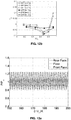
- Fig. 1b is taken from Zhang, X., Rona A. Edwards J. A. 1998 The effect of trailing edge geometry on cavity flow oscillation driven by a supersonic shear layer.
- the Aeronautical Journal Paper No. 2258, 129-136 Here a curved ramp is applied at the trailing edge of the cavity and extends from a point on the rear wall of the cavity to the upper edge. The downstream extent of the cavity is equal to the depth, D , of the cavity.
- Zhang et al. it is seen in Fig. 16 that there are significant pressure oscillations in the vicinity of the trailing edge of the cavity including a notable spike toward the start of the simulation.
- Figs. 16 there are significant pressure oscillations in the vicinity of the trailing edge of the cavity including a notable spike toward the start of the simulation.
- US Patent No. 6,446,904 discloses an aircraft weapons bay high frequency acoustic suppression apparatus that includes an extendable spoiler retractably received within an aircraft weapons bay.
- An injector unit is received within the spoiler for injecting high frequency pulses of pressurized gas into the airstream.
- the injector unit includes a resonance tube in outlet fluid communication with a nozzle.
- the pulsating output of the resonance tube perturbs the flow of pressurized gas in the nozzle, effectively breaking it up into discrete slugs or pulses which then exit the nozzle and enter the airstream.
- the high frequency perturbation of the airflow across the weapons bay, created by the aircraft weapons bay high frequency acoustic suppression apparatus effectively suppresses undesirable acoustic resonance within the open weapons bay.
- US Patent No. 5,340,054 discloses perturbation elements located at the leading edge of a cavity to eliminate oscillations found to occur in the cavities of a structural frame moving through a fluid.
- the perturbation elements reflect any remaining oscillations out of the cavity at the trailing edge and may take the form of multiple pins of various shape and geometrical arrangement which prevents the generation and growth of vortices causing acoustic oscillations.
- the reflection of remaining oscillations out of the cavity may be accomplished by ramping the trailing edge of the cavity.
- US Patent No. 5,699,981 discloses an aircraft cavity acoustic resonance suppression system comprising a small diameter, cylindrically shaped member disposed parallel to and spaced up to a distance corresponding to about three airflow boundary layer thicknesses from the surface of the aircraft near the leading edge of the cavity and transverse of airflow thereacross, and an actuator operatively connected to the member providing selective adjustment of the spacing between the member and the aircraft surface.
- US Patent No. 6,050,527 discloses a flow control device and method for eliminating flow-induced cavity resonance within a closed or nearly closed end flow passage having an inlet opening defined between an upstream inlet edge and a downstream inlet edge.
- the passage accepts exterior fluid flow therein via the opening.
- the flow control device includes a stationary inlet guide vane having a leading edge, a trailing edge, and a number of support members to connect the vane to the inlet.
- EP 1 714 871 discloses an acoustic resonator for use in an engine including a cavity having a volume, an aperture, and a passage connecting the aperture and the cavity.
- the aperture has a profiled surface at a leading edge for delaying separation of fluid entering the passage and for reducing losses caused by fluid separation.
- WO 2009/121986 discloses an aerodynamic thrust element which is positioned on a surface subject to friction with a fluid in order to reduce the friction.
- Each element includes a front convex area which has an approximately triangular profile and is connected via a depression area to a rear concave area also having an approximately triangular profile, the overall profile having an approximately rhombic shape.
- the aforementioned depression area enables a turbulence to be generated in the fluid as the element moves forward, which provides a thrust force that favours said forward movement.
- US Patent No. 3,578,264 discloses apparatus for boundary layer control for delay or prevention of flow separation and/or increase in rate of heat exchange between a surface and a fluid by an arrangement of surface elements which may take the form of concave depressions in the surface.
- US Patent No. 4,718,620 discloses a fluid flow control for reducing the drag associated with an upswept afterbody wherein a pair of ridges form symmetric flow channels arranged in an approximately helical fashion on either side of the afterbody so as to intersect at approximately the centerline of the undersurface.
- DE 10 2008 059 536 discloses a structure having shallow recesses distributed on an upper boundary surface, where edge sections of the recesses pass over a spherical convex transition area in the surface.
- the recesses include intermediate groove sections, respectively, where the groove sections are designed in a spherical cap-shaped manner.
- the rear face geometry of the cavity is modified so as to lie on a curved convex surface when viewed in cross-section along a longitudinal axis of the cavity.
- an elliptic shape has been found to cause a steady shear layer reattachment and thereby restrict the mass flowing in and out of the cavity, leading to significant reduction or complete alleviation of the oscillations.
- Such an embodiment will be referred to as Elliptic Rear Face (ERF).
- the ellipse has a semi-major axis twice the cavity depth and a semi-minor axis that exactly spans the complete depth of the cavity.
- different aspect ratios have also been found to be effective including an aspect ratio of 1:1, which defines a circular surface.
- a cross-section through a longitudinal axis of the convex curved surface may describe part of an ellipse, hyperbola, parabola, general polynomial, general trigonometric function, general hyperbolic function or any general exponential function.
- the invention differs from the above-referenced paper by Zhang et al. discussed above and shown in Fig. 1b in two respects.
- the curved surface preferably extends from or close to the floor of the cavity. More specifically, good results are expected if the curved surface intersects the rear wall of the cavity at a height no greater than 0.2 D , where D is the depth of the cavity. Even more preferably it extends from the floor of the cavity as shown in Fig. 4 .
- Zhang et al. the distance h shown in Fig.
- curved surface 1 may vary between 0.2 to 0.6 D , which means that the curved surface, which intersects the rear wall of the cavity at a height D-h, is displaced at least 0.4 D from the floor of the cavity. Furthermore, at the point where the curved surface in Zhang et al. intersects the rear wall of the cavity, there is a discontinuity in the surface gradient, which is avoided altogether in the preferred geometry of the present invention. Secondly, as noted, in the present invention particularly advantageous results have been obtained using an elliptical wall surface. As noted above, the difference is highlighted by comparing Fig. 16 of Zhang et al. with Fig. 13d of the present invention, both showing computed pressure oscillations in the vicinity of the trailing edge of the cavity.
- Fig. 4 is a schematic representation of an open cavity having modified geometry according to an embodiment of the invention.
- the solution according to the invention lies in the geometry itself and is achieved by altering the geometry at the flow impacting face and keeping the cavity size intact in terms of its length and depth.
- one of the proposed shapes is the elliptic shape of the forward facing step in the cavity to reduce the pressure oscillations and noise.
- two-dimensional CFD simulations were also made using commercially available software ANSYS-FLUENT.
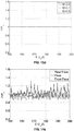
- the results shown in Figs. 5a and 5b demonstrate a complete alleviation of the oscillation.
- the pressure fluctuations (pressure normalized by the freestream pressure) with time (normalized by freestream velocity and the cavity length) are quite evident for the VRF configuration and are shown in Fig.
- the result of the present invention is to soften the impact on the forward facing edge by adopting an alteration to shape of the rear edge and the face of the cavity.
- VRF open rectangular cavity
- ERP altered elliptic edged cavity
- Cavity flow application spans the entire range of Mach numbers, starting from subsonic, transonic, supersonic to hypersonic flows. Specific examples include flows in landing gears of aircrafts, store separation from internal cavity, isolator flow control in scramjet intakes, cavity flame holder in combustion chambers, etc. Cavity flows are categorized as open or closed based on their length to depth (L/D) ratio. In open cavity flows with L/D ratio less than 10, strong pressure oscillations are created. These produce severe fluctuating pressures as well as noise levels in the vicinity of the cavity which could be detrimental to the structure housing the cavity and its integrity. Research has been carried out to understand these unsteady pressure characteristics (e.g., Alvarez et al. (2004)), and towards control of such loads by implementing various passive and active controlling techniques (e.g., Rowley & Williams (2006)).
- a shear layer is formed, which bridges the entire cavity length.
- a shear layer is formed, which bridges the entire cavity length.
- acoustic field is formed that propagates upstream and excites the shear layer formation at the LE and induces a Kelvin-Helmholtz type of instability which grows during convection towards TE to form an array of vortices.
- acoustic waves are regenerated which closes a feedback loop and provides self-sustained pressure oscillations. These oscillations and its associated resonance frequencies can be determined by phase relation across the feedback loop that provides constructive reinforcement of the waves.
- the spectrum of the pressure fluctuations inside the cavity is composed of broadband noise and narrow-band tones.
- the source of broadband is due to the free-stream and the shear layer.
- n m ⁇ ⁇ U ⁇ U c + M ⁇ 1 + 0.2 M ⁇ 2
- n the non-dimensional frequency (Strouhal number)
- U ⁇ and M ⁇ are the freestream velocity and Mach number, respectively
- m the integer mode number
- ⁇ an empirical constant associated with phase delay between vortex shedding and acoustic wave response in the cavity
- Uc the convection velocity of vortices over the cavity length.
- the cavity model used in the present study is a sting mounted type, and is designed in a modular form such as to change different parts of the cavity.
- the forebody of the cavity has 134mm length and a width of 69.4mm.
- the sidewalls of the cavity are made of fused silica windows to have an optical access inside the cavity depth for flow visualization and optical measurements.
- the regular rectangular cavity has a vertical rear face (VRF).
- VRF vertical rear face
- ERF elliptic shape
- Fig. 4 The geometric configuration followed is shown schematically in Fig. 4 .
- L the cavity length (L) is from the leading edge of cavity to the mid-plane of the elliptic wall (50% of the semi-major axis).
- Boundary layer measurements were required in order to provide accurate incoming velocity distribution to our 2D CFD simulations.
- In-house built staggered pitot boundary layer probes were used to measure the boundary layer over the model at the location of leading edge of the cavity.
- Oil flow visualization tests were carried out to obtain the surface flow field details using a proper mixture of Titanium Dioxide, Oleic acid, and lubricating oil. Mixture was sprayed evenly to all the surfaces of the cavity prior to each test run. Still images on all the surfaces were obtained after the test run and allowing the streak lines to dry. Standard Schlieren system with two 12", f/7.6 parabolic mirrors have been used to obtain shadowgraph images of the cavity overall flow field. A 50 Hz pulsed Xenon light source (3mm arc length) with energy of 1J and pulse width of 9 ⁇ s has been used to obtain the instantaneous flow images. The light source was synchronized with a 1MP CMOS Camera (Phantom V211) with a capability of 2kHz frame rate and controlled through PCC 2.4 software supplied by Vision Research.
- 1MP CMOS Camera Phantom V211
- Static and total pressures were measured using Honeywell sensors of suitable ranges. Pressure ports of 1.2mm diameter were made on the cavity floor (6 Nos.) and the cavity rear face (5 Nos.) for all the cavity configurations. The ports were connected to sensors through steel and polythene tubing in the tunnel. Sensor outputs were amplified and filtered using signal conditioner from National Instruments SCXI 1520/1125. Static pressures were sampled, averaged and recorded using a 16 bit NI PXI 6221 Data Card. Unsteady pressures were measured using Endevco 8510B-5 and 8530C-15 sensors, having natural frequency of 85kHz and 180kHz, respectively. Locations of unsteady pressure measurements on the cavity were at the mid-centerline of the front face and floor for VRF, and ERF.
- the entire computational domain was distributed with uniform quadrilateral cells having near wall cell spacing of the order of 0.09mm corresponding to y + of 13 on the cavity floor.
- a UDF Program was plugged into the inlet boundary condition to simulate turbulent boundary layer with 1/n-th power law similar to the experimental observation.
- Pressure far field boundary condition was applied to all the outer boundaries, and the no slip and no penetration wall boundary conditions were applied to cavity walls.
- Unit non-dimensional time is the time taken by the freestream flow to pass the cavity length.
- the figure shows the formation of vortices at the LE of cavity and their downstream convection towards the TE of cavity.
- Fig. 8b shows a fresh evolution of vortex near the LE and through Figs. 8c to 8i , the convecting vortex can be clearly seen.
- the complete cycle of formation of a vortex till the reformation of another vortex at the same location can be observed in Figs. 8b to 8i .
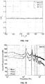
- Fig. 9 shows the results obtained through experiments and as well computations. There is a very good agreement between our 2D computations and Rossiter's empirical relation (indicated by various lines) and experiments. Our experimental results are also well predicted except for the 4th mode.
- the vorticity magnitude contour indicates an alleviation of the shedding of vortices from the cavity leading edge, leading to a smooth shear layer impact on the rear edge of the cavity.
- the streamlines (bottom row) also show a uniform circulatory flow for Elliptic Rear Face cavity (ERF) compared to a non-uniform oscillatory flow for Vertical Rear Face geometry(VRF). More importantly, the contours presented for the ERF configuration do not vary with time, indicating a 2-D steady state solution.
- the flow pattern on the front face and the cavity side face corroborate the off-centric two lobes and the flow lift-off appearing on the cavity floor, respectively.
- the oil flow pattern on the rear face of ERF ( Fig. 11b ) indicates two directions, one along the freestream and the other towards the cavity depth.
- the cavity floor surface flow indicates a difference in flow field compared to VRF.
- the flow separation has reduced along the length of the cavity floor.
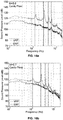
- Figs. 16a to 16c Comparison of measured sound pressure levels on the cavity floor for cavity with VRF and ERF for various Mach numbers are presented in Figs. 16a to 16c .
- M 0.9
- a clear demonstration of complete alleviation of tonal peaks dominant peak reduction of 30dB
- reduction in the average broadband spectra of around 10dB is observed ( Fig. 16a ).
- M 0.5
Landscapes
- Engineering & Computer Science (AREA)
- Physics & Mathematics (AREA)
- Fluid Mechanics (AREA)
- General Engineering & Computer Science (AREA)
- Mechanical Engineering (AREA)
- Aviation & Aerospace Engineering (AREA)
- Acoustics & Sound (AREA)
- Multimedia (AREA)
- Chemical & Material Sciences (AREA)
- Combustion & Propulsion (AREA)
- Analytical Chemistry (AREA)
- Aerodynamic Tests, Hydrodynamic Tests, Wind Tunnels, And Water Tanks (AREA)
- Soundproofing, Sound Blocking, And Sound Damping (AREA)
- Measurement Of Mechanical Vibrations Or Ultrasonic Waves (AREA)
Applications Claiming Priority (2)
| Application Number | Priority Date | Filing Date | Title |
|---|---|---|---|
| US201662289936P | 2016-02-02 | 2016-02-02 | |
| PCT/IL2017/050127 WO2017134666A1 (en) | 2016-02-02 | 2017-02-02 | Method and cavity for suppression of cavity flow oscillations and acoustic loads using curved rear face |
Publications (2)
| Publication Number | Publication Date |
|---|---|
| EP3411598A1 EP3411598A1 (en) | 2018-12-12 |
| EP3411598B1 true EP3411598B1 (en) | 2019-08-21 |
Family
ID=58428326
Family Applications (1)
| Application Number | Title | Priority Date | Filing Date |
|---|---|---|---|
| EP17714026.6A Active EP3411598B1 (en) | 2016-02-02 | 2017-02-02 | Method and cavity for suppression of cavity flow oscillations and acoustic loads using curved rear face |
Country Status (5)
| Country | Link |
|---|---|
| US (1) | US10823207B2 (https=) |
| EP (1) | EP3411598B1 (https=) |
| JP (1) | JP6917030B2 (https=) |
| KR (1) | KR20180114089A (https=) |
| WO (1) | WO2017134666A1 (https=) |
Families Citing this family (5)
| Publication number | Priority date | Publication date | Assignee | Title |
|---|---|---|---|---|
| US10876732B2 (en) * | 2016-10-19 | 2020-12-29 | Gloyer-Taylor Laboratories Llc | Scalable acoustically-stable combustion chamber and design methods |
| JP6691896B2 (ja) * | 2017-08-25 | 2020-05-13 | 三菱重工業株式会社 | 航空機 |
| CA3037923C (en) | 2018-03-29 | 2025-12-09 | Bombardier Inc. | System and method for improving the operation of an aircraft |
| TR202022407A1 (tr) * | 2020-12-30 | 2022-07-21 | Tusas Tuerk Havacilik Ve Uzay Sanayii Anonim Sirketi | Bir kavite. |
| FR3120699B1 (fr) * | 2021-03-10 | 2023-03-17 | Airbus Operations Sas | Dispositif de mesure acoustique |
Family Cites Families (14)
| Publication number | Priority date | Publication date | Assignee | Title |
|---|---|---|---|---|
| US3578264A (en) | 1968-07-09 | 1971-05-11 | Battelle Development Corp | Boundary layer control of flow separation and heat exchange |
| US4718620A (en) | 1984-10-15 | 1988-01-12 | Braden John A | Terraced channels for reducing afterbody drag |
| US5340054A (en) | 1991-02-20 | 1994-08-23 | The United States Of America As Represented By The Secretary Of The Navy | Suppressor of oscillations in airframe cavities |
| US5699981A (en) | 1996-03-18 | 1997-12-23 | The United States Of America As Represented By The Secretary Of The Air Force | Aircraft cavity acoustic resonance suppression system |
| US6050527A (en) | 1997-12-19 | 2000-04-18 | The Boeing Company | Flow control device to eliminate cavity resonance |
| US6446904B1 (en) | 2001-10-05 | 2002-09-10 | The United States Of America As Represented By The Secretary Of The Air Force | Aircraft weapons bay high frequency acoustic suppression apparatus |
| US6739554B1 (en) * | 2003-06-02 | 2004-05-25 | The United States Of America As Represented By The Secretary Of The Air Force | Aircraft weapons bay acoustic resonance suppression system |
| US7322195B2 (en) | 2005-04-19 | 2008-01-29 | United Technologies Corporation | Acoustic dampers |
| US8684040B2 (en) * | 2007-05-25 | 2014-04-01 | The Regents Of The University Of Michigan | Reduction of vortex induced forces and motion through surface roughness control |
| NL1035216C2 (nl) * | 2007-07-24 | 2009-01-27 | Kick Off Ltd | Wrijvingsweerstand reducerende laag en werkwijze voor de vervaardiging daarvan. |
| ES2326356B1 (es) * | 2008-03-31 | 2010-07-13 | Maria Desamparados Segura Mecho | Elemento impulsor aerodinamico. |
| DE102008059536A1 (de) | 2008-11-29 | 2010-06-02 | Eugen Radtke | Oberflächenstruktur |
| JP3165679U (ja) * | 2010-11-18 | 2011-01-27 | 瑞麟 林 | 流体に対する抵抗体 |
| GB201213451D0 (en) * | 2012-07-27 | 2012-09-12 | Imp Innovations Ltd | Drag reduction |
-
2017
- 2017-02-02 KR KR1020187025346A patent/KR20180114089A/ko not_active Withdrawn
- 2017-02-02 US US16/074,963 patent/US10823207B2/en active Active
- 2017-02-02 EP EP17714026.6A patent/EP3411598B1/en active Active
- 2017-02-02 JP JP2018541286A patent/JP6917030B2/ja active Active
- 2017-02-02 WO PCT/IL2017/050127 patent/WO2017134666A1/en not_active Ceased
Non-Patent Citations (1)
| Title |
|---|
| None * |
Also Published As
| Publication number | Publication date |
|---|---|
| US10823207B2 (en) | 2020-11-03 |
| EP3411598A1 (en) | 2018-12-12 |
| US20190040883A1 (en) | 2019-02-07 |
| JP2019510174A (ja) | 2019-04-11 |
| WO2017134666A1 (en) | 2017-08-10 |
| JP6917030B2 (ja) | 2021-08-11 |
| KR20180114089A (ko) | 2018-10-17 |
Similar Documents
| Publication | Publication Date | Title |
|---|---|---|
| EP3411598B1 (en) | Method and cavity for suppression of cavity flow oscillations and acoustic loads using curved rear face | |
| Verma et al. | Control of incident shock-induced separation using vane-type vortex-generating devices | |
| Srikant et al. | Unstart detection in a simplified-geometry hypersonic inlet-isolator flow | |
| Fedorov et al. | Evolution of disturbances in entropy layer on blunted plate in supersonic flow | |
| Downs III et al. | Tollmien–Schlichting wave growth over spanwise-periodic surface patterns | |
| Akansu et al. | Control of flow around a square prism by slot jet injection from the rear surface | |
| Verma et al. | Transition control of Mach to regular reflection induced interaction using an array of micro ramp vane-type vortex generators | |
| Saric et al. | Influence of high-amplitude noise on boundary-layer transition to turbulence | |
| Krishna et al. | Effect of cavity rear wall modifications on pressure fluctuations at supersonic speed | |
| Perng et al. | Suppression of pressure oscillations in high-Mach-number, turbulent, cavity flow | |
| Sinha et al. | High fidelity simulation and measurements of aircraft weapons bay dynamics | |
| Wagner et al. | Pulse-burst PIV measurements of transient phenomena in a shock tube | |
| Gefroh et al. | Aeroelastically deflecting flaps for shock/boundary-layer interaction control | |
| Das et al. | Effect of rear face geometry on the open cavity oscillatory flow at M= 0.9 | |
| Li et al. | Experimental study on aerodynamic noise characteristics and control of non-fully open low-speed cavities | |
| Naigle | Flow control of compressible dynamic stall using vortex generator jets | |
| Cura et al. | Linear modeling of a family of turbulent separation bubbles | |
| Uruba | Flow control using synthetic jet actuators | |
| El Hassan et al. | Non-oscillating/oscillating shear layer over a large deep cavity at low-subsonic speeds | |
| Wagner et al. | Time-Resolved PIV in a Shock Tube using a Pulse-Burst Laser. | |
| Casper et al. | Complex Geometry Effects on Supersonic Cavity Flows. | |
| Sivasubramanian et al. | Numerical investigation of wavepackets in a hypersonic cone boundary layer at Mach 6 | |
| Yatskikh et al. | Numerical Simulation of the Growth of Localized Disturbances in a Supersonic Boundary Layer over a Plate with Longitudinal Slots | |
| Funderburk et al. | Experimental Investigation of Corner Shock Boundary Layer Interactions | |
| Nilavarasan | Flare Induced Shock Wave–Boundary Layer Interaction and its Control using Micro Vortex Generators |
Legal Events
| Date | Code | Title | Description |
|---|---|---|---|
| STAA | Information on the status of an ep patent application or granted ep patent |
Free format text: STATUS: UNKNOWN |
|
| STAA | Information on the status of an ep patent application or granted ep patent |
Free format text: STATUS: THE INTERNATIONAL PUBLICATION HAS BEEN MADE |
|
| PUAI | Public reference made under article 153(3) epc to a published international application that has entered the european phase |
Free format text: ORIGINAL CODE: 0009012 |
|
| STAA | Information on the status of an ep patent application or granted ep patent |
Free format text: STATUS: REQUEST FOR EXAMINATION WAS MADE |
|
| 17P | Request for examination filed |
Effective date: 20180828 |
|
| AK | Designated contracting states |
Kind code of ref document: A1 Designated state(s): AL AT BE BG CH CY CZ DE DK EE ES FI FR GB GR HR HU IE IS IT LI LT LU LV MC MK MT NL NO PL PT RO RS SE SI SK SM TR |
|
| AX | Request for extension of the european patent |
Extension state: BA ME |
|
| RIN1 | Information on inventor provided before grant (corrected) |
Inventor name: COHEN, JACOB Inventor name: DAS, SUDIP |
|
| GRAP | Despatch of communication of intention to grant a patent |
Free format text: ORIGINAL CODE: EPIDOSNIGR1 |
|
| STAA | Information on the status of an ep patent application or granted ep patent |
Free format text: STATUS: GRANT OF PATENT IS INTENDED |
|
| DAX | Request for extension of the european patent (deleted) | ||
| INTG | Intention to grant announced |
Effective date: 20190404 |
|
| DAV | Request for validation of the european patent (deleted) | ||
| RIN1 | Information on inventor provided before grant (corrected) |
Inventor name: DAS, SUDIP Inventor name: COHEN, JACOB |
|
| GRAS | Grant fee paid |
Free format text: ORIGINAL CODE: EPIDOSNIGR3 |
|
| GRAA | (expected) grant |
Free format text: ORIGINAL CODE: 0009210 |
|
| STAA | Information on the status of an ep patent application or granted ep patent |
Free format text: STATUS: THE PATENT HAS BEEN GRANTED |
|
| AK | Designated contracting states |
Kind code of ref document: B1 Designated state(s): AL AT BE BG CH CY CZ DE DK EE ES FI FR GB GR HR HU IE IS IT LI LT LU LV MC MK MT NL NO PL PT RO RS SE SI SK SM TR |
|
| REG | Reference to a national code |
Ref country code: GB Ref legal event code: FG4D |
|
| REG | Reference to a national code |
Ref country code: CH Ref legal event code: EP |
|
| REG | Reference to a national code |
Ref country code: DE Ref legal event code: R096 Ref document number: 602017006384 Country of ref document: DE |
|
| REG | Reference to a national code |
Ref country code: AT Ref legal event code: REF Ref document number: 1170091 Country of ref document: AT Kind code of ref document: T Effective date: 20190915 |
|
| REG | Reference to a national code |
Ref country code: IE Ref legal event code: FG4D |
|
| REG | Reference to a national code |
Ref country code: LT Ref legal event code: MG4D |
|
| REG | Reference to a national code |
Ref country code: NL Ref legal event code: MP Effective date: 20190821 |
|
| PG25 | Lapsed in a contracting state [announced via postgrant information from national office to epo] |
Ref country code: FI Free format text: LAPSE BECAUSE OF FAILURE TO SUBMIT A TRANSLATION OF THE DESCRIPTION OR TO PAY THE FEE WITHIN THE PRESCRIBED TIME-LIMIT Effective date: 20190821 Ref country code: NO Free format text: LAPSE BECAUSE OF FAILURE TO SUBMIT A TRANSLATION OF THE DESCRIPTION OR TO PAY THE FEE WITHIN THE PRESCRIBED TIME-LIMIT Effective date: 20191121 Ref country code: BG Free format text: LAPSE BECAUSE OF FAILURE TO SUBMIT A TRANSLATION OF THE DESCRIPTION OR TO PAY THE FEE WITHIN THE PRESCRIBED TIME-LIMIT Effective date: 20191121 Ref country code: SE Free format text: LAPSE BECAUSE OF FAILURE TO SUBMIT A TRANSLATION OF THE DESCRIPTION OR TO PAY THE FEE WITHIN THE PRESCRIBED TIME-LIMIT Effective date: 20190821 Ref country code: NL Free format text: LAPSE BECAUSE OF FAILURE TO SUBMIT A TRANSLATION OF THE DESCRIPTION OR TO PAY THE FEE WITHIN THE PRESCRIBED TIME-LIMIT Effective date: 20190821 Ref country code: HR Free format text: LAPSE BECAUSE OF FAILURE TO SUBMIT A TRANSLATION OF THE DESCRIPTION OR TO PAY THE FEE WITHIN THE PRESCRIBED TIME-LIMIT Effective date: 20190821 Ref country code: LT Free format text: LAPSE BECAUSE OF FAILURE TO SUBMIT A TRANSLATION OF THE DESCRIPTION OR TO PAY THE FEE WITHIN THE PRESCRIBED TIME-LIMIT Effective date: 20190821 Ref country code: PT Free format text: LAPSE BECAUSE OF FAILURE TO SUBMIT A TRANSLATION OF THE DESCRIPTION OR TO PAY THE FEE WITHIN THE PRESCRIBED TIME-LIMIT Effective date: 20191223 |
|
| PG25 | Lapsed in a contracting state [announced via postgrant information from national office to epo] |
Ref country code: RS Free format text: LAPSE BECAUSE OF FAILURE TO SUBMIT A TRANSLATION OF THE DESCRIPTION OR TO PAY THE FEE WITHIN THE PRESCRIBED TIME-LIMIT Effective date: 20190821 Ref country code: IS Free format text: LAPSE BECAUSE OF FAILURE TO SUBMIT A TRANSLATION OF THE DESCRIPTION OR TO PAY THE FEE WITHIN THE PRESCRIBED TIME-LIMIT Effective date: 20191221 Ref country code: GR Free format text: LAPSE BECAUSE OF FAILURE TO SUBMIT A TRANSLATION OF THE DESCRIPTION OR TO PAY THE FEE WITHIN THE PRESCRIBED TIME-LIMIT Effective date: 20191122 Ref country code: AL Free format text: LAPSE BECAUSE OF FAILURE TO SUBMIT A TRANSLATION OF THE DESCRIPTION OR TO PAY THE FEE WITHIN THE PRESCRIBED TIME-LIMIT Effective date: 20190821 Ref country code: LV Free format text: LAPSE BECAUSE OF FAILURE TO SUBMIT A TRANSLATION OF THE DESCRIPTION OR TO PAY THE FEE WITHIN THE PRESCRIBED TIME-LIMIT Effective date: 20190821 Ref country code: ES Free format text: LAPSE BECAUSE OF FAILURE TO SUBMIT A TRANSLATION OF THE DESCRIPTION OR TO PAY THE FEE WITHIN THE PRESCRIBED TIME-LIMIT Effective date: 20190821 |
|
| REG | Reference to a national code |
Ref country code: AT Ref legal event code: MK05 Ref document number: 1170091 Country of ref document: AT Kind code of ref document: T Effective date: 20190821 |
|
| PG25 | Lapsed in a contracting state [announced via postgrant information from national office to epo] |
Ref country code: TR Free format text: LAPSE BECAUSE OF FAILURE TO SUBMIT A TRANSLATION OF THE DESCRIPTION OR TO PAY THE FEE WITHIN THE PRESCRIBED TIME-LIMIT Effective date: 20190821 |
|
| PG25 | Lapsed in a contracting state [announced via postgrant information from national office to epo] |
Ref country code: EE Free format text: LAPSE BECAUSE OF FAILURE TO SUBMIT A TRANSLATION OF THE DESCRIPTION OR TO PAY THE FEE WITHIN THE PRESCRIBED TIME-LIMIT Effective date: 20190821 Ref country code: DK Free format text: LAPSE BECAUSE OF FAILURE TO SUBMIT A TRANSLATION OF THE DESCRIPTION OR TO PAY THE FEE WITHIN THE PRESCRIBED TIME-LIMIT Effective date: 20190821 Ref country code: PL Free format text: LAPSE BECAUSE OF FAILURE TO SUBMIT A TRANSLATION OF THE DESCRIPTION OR TO PAY THE FEE WITHIN THE PRESCRIBED TIME-LIMIT Effective date: 20190821 Ref country code: IT Free format text: LAPSE BECAUSE OF FAILURE TO SUBMIT A TRANSLATION OF THE DESCRIPTION OR TO PAY THE FEE WITHIN THE PRESCRIBED TIME-LIMIT Effective date: 20190821 Ref country code: AT Free format text: LAPSE BECAUSE OF FAILURE TO SUBMIT A TRANSLATION OF THE DESCRIPTION OR TO PAY THE FEE WITHIN THE PRESCRIBED TIME-LIMIT Effective date: 20190821 Ref country code: RO Free format text: LAPSE BECAUSE OF FAILURE TO SUBMIT A TRANSLATION OF THE DESCRIPTION OR TO PAY THE FEE WITHIN THE PRESCRIBED TIME-LIMIT Effective date: 20190821 |
|
| PG25 | Lapsed in a contracting state [announced via postgrant information from national office to epo] |
Ref country code: SK Free format text: LAPSE BECAUSE OF FAILURE TO SUBMIT A TRANSLATION OF THE DESCRIPTION OR TO PAY THE FEE WITHIN THE PRESCRIBED TIME-LIMIT Effective date: 20190821 Ref country code: SM Free format text: LAPSE BECAUSE OF FAILURE TO SUBMIT A TRANSLATION OF THE DESCRIPTION OR TO PAY THE FEE WITHIN THE PRESCRIBED TIME-LIMIT Effective date: 20190821 Ref country code: CZ Free format text: LAPSE BECAUSE OF FAILURE TO SUBMIT A TRANSLATION OF THE DESCRIPTION OR TO PAY THE FEE WITHIN THE PRESCRIBED TIME-LIMIT Effective date: 20190821 Ref country code: IS Free format text: LAPSE BECAUSE OF FAILURE TO SUBMIT A TRANSLATION OF THE DESCRIPTION OR TO PAY THE FEE WITHIN THE PRESCRIBED TIME-LIMIT Effective date: 20200224 |
|
| REG | Reference to a national code |
Ref country code: DE Ref legal event code: R097 Ref document number: 602017006384 Country of ref document: DE |
|
| PLBE | No opposition filed within time limit |
Free format text: ORIGINAL CODE: 0009261 |
|
| STAA | Information on the status of an ep patent application or granted ep patent |
Free format text: STATUS: NO OPPOSITION FILED WITHIN TIME LIMIT |
|
| PG2D | Information on lapse in contracting state deleted |
Ref country code: IS |
|
| 26N | No opposition filed |
Effective date: 20200603 |
|
| REG | Reference to a national code |
Ref country code: CH Ref legal event code: PL |
|
| REG | Reference to a national code |
Ref country code: BE Ref legal event code: MM Effective date: 20200229 |
|
| PG25 | Lapsed in a contracting state [announced via postgrant information from national office to epo] |
Ref country code: LU Free format text: LAPSE BECAUSE OF NON-PAYMENT OF DUE FEES Effective date: 20200202 Ref country code: MC Free format text: LAPSE BECAUSE OF FAILURE TO SUBMIT A TRANSLATION OF THE DESCRIPTION OR TO PAY THE FEE WITHIN THE PRESCRIBED TIME-LIMIT Effective date: 20190821 |
|
| PG25 | Lapsed in a contracting state [announced via postgrant information from national office to epo] |
Ref country code: CH Free format text: LAPSE BECAUSE OF NON-PAYMENT OF DUE FEES Effective date: 20200229 Ref country code: LI Free format text: LAPSE BECAUSE OF NON-PAYMENT OF DUE FEES Effective date: 20200229 |
|
| PG25 | Lapsed in a contracting state [announced via postgrant information from national office to epo] |
Ref country code: IE Free format text: LAPSE BECAUSE OF NON-PAYMENT OF DUE FEES Effective date: 20200202 |
|
| PG25 | Lapsed in a contracting state [announced via postgrant information from national office to epo] |
Ref country code: BE Free format text: LAPSE BECAUSE OF NON-PAYMENT OF DUE FEES Effective date: 20200229 |
|
| PG25 | Lapsed in a contracting state [announced via postgrant information from national office to epo] |
Ref country code: MT Free format text: LAPSE BECAUSE OF FAILURE TO SUBMIT A TRANSLATION OF THE DESCRIPTION OR TO PAY THE FEE WITHIN THE PRESCRIBED TIME-LIMIT Effective date: 20190821 Ref country code: CY Free format text: LAPSE BECAUSE OF FAILURE TO SUBMIT A TRANSLATION OF THE DESCRIPTION OR TO PAY THE FEE WITHIN THE PRESCRIBED TIME-LIMIT Effective date: 20190821 |
|
| PG25 | Lapsed in a contracting state [announced via postgrant information from national office to epo] |
Ref country code: MK Free format text: LAPSE BECAUSE OF FAILURE TO SUBMIT A TRANSLATION OF THE DESCRIPTION OR TO PAY THE FEE WITHIN THE PRESCRIBED TIME-LIMIT Effective date: 20190821 |
|
| REG | Reference to a national code |
Ref country code: DE Ref legal event code: R082 Ref document number: 602017006384 Country of ref document: DE Representative=s name: PATENTANWAELTE KLUIN DEBELIUS WEBER PARTG MBB, DE |
|
| PG25 | Lapsed in a contracting state [announced via postgrant information from national office to epo] |
Ref country code: SI Free format text: LAPSE BECAUSE OF FAILURE TO SUBMIT A TRANSLATION OF THE DESCRIPTION OR TO PAY THE FEE WITHIN THE PRESCRIBED TIME-LIMIT Effective date: 20190821 |
|
| PGFP | Annual fee paid to national office [announced via postgrant information from national office to epo] |
Ref country code: GB Payment date: 20260122 Year of fee payment: 10 |
|
| PGFP | Annual fee paid to national office [announced via postgrant information from national office to epo] |
Ref country code: DE Payment date: 20260120 Year of fee payment: 10 |
|
| PGFP | Annual fee paid to national office [announced via postgrant information from national office to epo] |
Ref country code: FR Payment date: 20260123 Year of fee payment: 10 |