EP3410804B1 - Benutzerendgerät, drahtlose basisstation und drahtloskommunikationsverfahren - Google Patents
Benutzerendgerät, drahtlose basisstation und drahtloskommunikationsverfahren Download PDFInfo
- Publication number
- EP3410804B1 EP3410804B1 EP17747569.6A EP17747569A EP3410804B1 EP 3410804 B1 EP3410804 B1 EP 3410804B1 EP 17747569 A EP17747569 A EP 17747569A EP 3410804 B1 EP3410804 B1 EP 3410804B1
- Authority
- EP
- European Patent Office
- Prior art keywords
- transmission
- downlink control
- unit
- dci
- subframe
- Prior art date
- Legal status (The legal status is an assumption and is not a legal conclusion. Google has not performed a legal analysis and makes no representation as to the accuracy of the status listed.)
- Active
Links
- 238000004891 communication Methods 0.000 title claims description 61
- 238000000034 method Methods 0.000 title claims description 25
- 230000005540 biological transmission Effects 0.000 claims description 199
- 238000012545 processing Methods 0.000 description 69
- 238000010586 diagram Methods 0.000 description 42
- 238000005259 measurement Methods 0.000 description 26
- 230000007274 generation of a signal involved in cell-cell signaling Effects 0.000 description 24
- 230000003252 repetitive effect Effects 0.000 description 19
- 238000013507 mapping Methods 0.000 description 17
- 230000011664 signaling Effects 0.000 description 15
- 238000013468 resource allocation Methods 0.000 description 13
- 238000005516 engineering process Methods 0.000 description 7
- 230000004044 response Effects 0.000 description 7
- 238000010295 mobile communication Methods 0.000 description 6
- 230000001413 cellular effect Effects 0.000 description 5
- 230000006870 function Effects 0.000 description 5
- 230000009467 reduction Effects 0.000 description 5
- 239000000969 carrier Substances 0.000 description 3
- 238000013461 design Methods 0.000 description 3
- 230000006872 improvement Effects 0.000 description 3
- 238000007726 management method Methods 0.000 description 3
- 230000008569 process Effects 0.000 description 3
- 238000012937 correction Methods 0.000 description 2
- 230000000694 effects Effects 0.000 description 2
- 230000005611 electricity Effects 0.000 description 2
- 239000012634 fragment Substances 0.000 description 2
- 230000007774 longterm Effects 0.000 description 2
- 238000012544 monitoring process Methods 0.000 description 2
- 230000003287 optical effect Effects 0.000 description 2
- 239000013307 optical fiber Substances 0.000 description 2
- 239000010454 slate Substances 0.000 description 2
- 239000002699 waste material Substances 0.000 description 2
- 101000741965 Homo sapiens Inactive tyrosine-protein kinase PRAG1 Proteins 0.000 description 1
- 102100038659 Inactive tyrosine-protein kinase PRAG1 Human genes 0.000 description 1
- 101150071746 Pbsn gene Proteins 0.000 description 1
- 230000002776 aggregation Effects 0.000 description 1
- 238000004220 aggregation Methods 0.000 description 1
- 238000004458 analytical method Methods 0.000 description 1
- 238000006243 chemical reaction Methods 0.000 description 1
- 230000008878 coupling Effects 0.000 description 1
- 238000010168 coupling process Methods 0.000 description 1
- 238000005859 coupling reaction Methods 0.000 description 1
- 125000004122 cyclic group Chemical group 0.000 description 1
- 238000001514 detection method Methods 0.000 description 1
- 230000006866 deterioration Effects 0.000 description 1
- 239000006249 magnetic particle Substances 0.000 description 1
- 238000005457 optimization Methods 0.000 description 1
- 230000002093 peripheral effect Effects 0.000 description 1
Images


Classifications
-
- H—ELECTRICITY
- H04—ELECTRIC COMMUNICATION TECHNIQUE
- H04L—TRANSMISSION OF DIGITAL INFORMATION, e.g. TELEGRAPHIC COMMUNICATION
- H04L1/00—Arrangements for detecting or preventing errors in the information received
- H04L1/12—Arrangements for detecting or preventing errors in the information received by using return channel
- H04L1/16—Arrangements for detecting or preventing errors in the information received by using return channel in which the return channel carries supervisory signals, e.g. repetition request signals
- H04L1/18—Automatic repetition systems, e.g. Van Duuren systems
- H04L1/1812—Hybrid protocols; Hybrid automatic repeat request [HARQ]
- H04L1/1816—Hybrid protocols; Hybrid automatic repeat request [HARQ] with retransmission of the same, encoded, message
-
- H—ELECTRICITY
- H04—ELECTRIC COMMUNICATION TECHNIQUE
- H04L—TRANSMISSION OF DIGITAL INFORMATION, e.g. TELEGRAPHIC COMMUNICATION
- H04L5/00—Arrangements affording multiple use of the transmission path
- H04L5/003—Arrangements for allocating sub-channels of the transmission path
- H04L5/0053—Allocation of signaling, i.e. of overhead other than pilot signals
-
- H—ELECTRICITY
- H04—ELECTRIC COMMUNICATION TECHNIQUE
- H04L—TRANSMISSION OF DIGITAL INFORMATION, e.g. TELEGRAPHIC COMMUNICATION
- H04L5/00—Arrangements affording multiple use of the transmission path
- H04L5/003—Arrangements for allocating sub-channels of the transmission path
- H04L5/0058—Allocation criteria
- H04L5/0064—Rate requirement of the data, e.g. scalable bandwidth, data priority
-
- H—ELECTRICITY
- H04—ELECTRIC COMMUNICATION TECHNIQUE
- H04L—TRANSMISSION OF DIGITAL INFORMATION, e.g. TELEGRAPHIC COMMUNICATION
- H04L5/00—Arrangements affording multiple use of the transmission path
- H04L5/003—Arrangements for allocating sub-channels of the transmission path
- H04L5/0078—Timing of allocation
- H04L5/0082—Timing of allocation at predetermined intervals
-
- H—ELECTRICITY
- H04—ELECTRIC COMMUNICATION TECHNIQUE
- H04L—TRANSMISSION OF DIGITAL INFORMATION, e.g. TELEGRAPHIC COMMUNICATION
- H04L5/00—Arrangements affording multiple use of the transmission path
- H04L5/0091—Signaling for the administration of the divided path
- H04L5/0092—Indication of how the channel is divided
-
- H—ELECTRICITY
- H04—ELECTRIC COMMUNICATION TECHNIQUE
- H04W—WIRELESS COMMUNICATION NETWORKS
- H04W4/00—Services specially adapted for wireless communication networks; Facilities therefor
- H04W4/70—Services for machine-to-machine communication [M2M] or machine type communication [MTC]
-
- H—ELECTRICITY
- H04—ELECTRIC COMMUNICATION TECHNIQUE
- H04W—WIRELESS COMMUNICATION NETWORKS
- H04W72/00—Local resource management
- H04W72/04—Wireless resource allocation
- H04W72/044—Wireless resource allocation based on the type of the allocated resource
- H04W72/0446—Resources in time domain, e.g. slots or frames
-
- H—ELECTRICITY
- H04—ELECTRIC COMMUNICATION TECHNIQUE
- H04W—WIRELESS COMMUNICATION NETWORKS
- H04W72/00—Local resource management
- H04W72/20—Control channels or signalling for resource management
- H04W72/23—Control channels or signalling for resource management in the downlink direction of a wireless link, i.e. towards a terminal
-
- H—ELECTRICITY
- H04—ELECTRIC COMMUNICATION TECHNIQUE
- H04L—TRANSMISSION OF DIGITAL INFORMATION, e.g. TELEGRAPHIC COMMUNICATION
- H04L5/00—Arrangements affording multiple use of the transmission path
- H04L5/003—Arrangements for allocating sub-channels of the transmission path
- H04L5/0044—Arrangements for allocating sub-channels of the transmission path allocation of payload
-
- H—ELECTRICITY
- H04—ELECTRIC COMMUNICATION TECHNIQUE
- H04W—WIRELESS COMMUNICATION NETWORKS
- H04W72/00—Local resource management
- H04W72/12—Wireless traffic scheduling
- H04W72/1263—Mapping of traffic onto schedule, e.g. scheduled allocation or multiplexing of flows
- H04W72/1268—Mapping of traffic onto schedule, e.g. scheduled allocation or multiplexing of flows of uplink data flows
Definitions
- the present invention relates to a user terminal, a radio base station, and a radio communication method in a next generation mobile communication system.
- LTE long term evolution
- Non Patent Literature 1 LTE-Advanced (LTE-A)
- LTE-A LTE-Advanced
- FAA future radio access
- 4G 5G
- 5G LTE Rel. 13, 14, 15, etc.
- Non Patent Literature 2 MTC user equipment
- the authors analyse the timing relationships between UL/DL control and data channels for HARQ operation.
- the timing for UEs operating or not operating coverage enhancement is proposed to follow the procedure as illustrated.
- the timing relationships depend on the offsets between M-PDCCH monitoring subframes.
- the authors discuss DL and UL timing relationships for NB-IoT.
- the authors propose that the NB-PDSCH transmission can begin either in the first subframe following the last repetition of the NB-PDCCH or after a delay indicated to the UE, the timing of UL ACK/NACK transmission relative to the last repetition of NB-PDSCH follows legacy timing, and the timing of NB-PUSCH transmission relative to the last repetition of NB-PDCCH follows legacy timing.
- the timing interval of scheduling window for UL grant and scheduling window for associated NB-PUSCH is fixed as one scheduling window.
- Location of NB-PUSCH in scheduling window can be dynamic signaled by DCI.
- the authors also propose that DL scheduling is based on scheduling window, and location of NB-PDSCH in scheduling window can be dynamic signaled by DCT.
- Timing Relationships In the contribution entitled " Timing Relationships" (XP051053418 ), the authors disclose fixed timing relationships in LTE physical layer including DL grant->PDSCH transmission, UL grant->PUSCH transmission, PDSCH transmission->UL A/N, PUSCH-> DLA/N and PUSCH->PUSCH retransmission for both FDD and TDD. The authors discuss the timeline design in NB-IoT and provide their proposals.
- US 2014/0105191 A1 discloses a wireless communication system.
- a method for performing HARQ (hybrid automatic repeat request) retransmission by a communication device in a wireless communication system comprising: initially transmitting a data block to a Base Station (BS); attempting PDCCH (physical downlink control channel detection) in a predetermined time interval including a plurality of subframes after transmission of an uplink channel signal; and retransmitting the data block when a PDCCH signal indicating retransmission of the data block is detected in the predetermined time interval, wherein reception of a PHICH (physical hybrid ARQ indicator channel) corresponding to initial transmission of the data block is skipped.
- BS Base Station
- PDCCH physical downlink control channel detection
- LC-MTC low-cost (LC)-MTC equipment
- LC-MTC UE low-cost (LC)-MTC equipment
- LC-MTC UE low-cost (LC)-MTC equipment
- LC-MTC UE low-cost (LC)-MTC equipment
- LC-MTC UE low-cost (LC)-MTC equipment
- LC-MTC UE LTE communication in an extremely narrow band
- NB-IoT narrow band Internet of Things
- NB-LTE narrow band LTE
- NB cellular IoT narrow band cellular Internet of Things
- clean slate narrow band cellular Internet of Things
- NB-IoT used herein includes the NB-LTE, the NB cellular IoT, the clean slate, and the like described above.
- NB-IoT equipment a user terminal supporting the NB-IoT (hereinafter, referred to as NB-IoT equipment) is limited to a band (for example, 180 kHz or one resource block (RB); also referred to as, for example, physical resource block (PRB)) which is narrower than the minimum system band (1.4 MHz) of the existing LTE system (for example, the LTE system before Rel. 12).
- RB resource block
- PRB physical resource block
- the present invention is made in consideration of such a situation, and an object of the present invention is to provide a user terminal, a radio base station, and a radio communication method that make it possible to appropriately perform communication even when resource allocation is controlled by a frequency unit (for example, a subcarrier unit) that is smaller than the resource allocation unit in the existing LTE system.
- a frequency unit for example, a subcarrier unit
- the present invention provides a user terminal in accordance with claim 1.
- the present invention also provides a user terminal in accordance with claim 4.
- the present invention also provides a radio base station in accordance with claim 5.
- the present invention also provides a radio communication method in accordance with claim 6.
- the present invention makes it possible to appropriately perform communication even when resource allocation is controlled by a frequency unit (for example, a subcarrier unit) that is smaller than the resource allocation unit in the existing LTE system.
- a frequency unit for example, a subcarrier unit
- Simplification of a hardware configuration of NB-IoT equipment by allowing reduction of process capability has been under consideration.
- NB-IoT equipment application of reduction of a peak rate, limitation of transport block size (TBS), limitation of a resource block (RB, also referred to as, for example, physical a resource block (PRB)), limitation of reception radio frequency (RF), and the like have been under consideration, as compared with an existing user terminal (for example, LTE equipment before Rel. 12).
- TBS transport block size
- RB resource block
- PRB physical a resource block
- RF reception radio frequency
- an upper limit of the usable band of the NB-IoT equipment is limited to a predetermined narrow band (NB, for example, 180 kHz or 1.4 MHz).
- the predetermined narrow band may be the same as the minimum system band (for example, 1.4 MHz, six PRBs) of the existing LTE system (the LTE system before Rel. 12, hereinafter, also simply referred to as the LTE system), or may be a portion of the band of the existing LTE system (for example, 180 kHz, 1 PRB).
- the NB-IoT equipment also regarded as equipment that has the upper limit of the usable band lower than the usable band of the existing LTE equipment, or equipment that can perform transmission and/or reception (hereinafter, referred to as transmission/reception) in a band (for example, a band narrower than 1.4 MHz) narrower than the band of the existing LTE equipment.
- a band for example, a band narrower than 1.4 MHz
- Operation of the NB-IoT equipment in the system band of the LTE system has been under consideration in view of backward compatibility with the existing LTE system.
- frequency multiplexing may be supported between the NB-IoT equipment with a limited band and the existing LTE equipment without a limited band.
- the NB-IoT may be operated with use of a guard band between carriers adjacent to the LTE system band, or an exclusive frequency, in addition to in the LTE system band.
- FIG. 1 is a diagram illustrating an allocation example of a narrow band that serves as the usable band of the NB-IoT equipment.
- the usable band of the NB-IoT equipment is set to a portion of the system band (for example, 20 MHz) of the LTE system.
- the usable band of the NB-IoT equipment is assumed to be set to 180 kHz, without limitation.
- the usable band of the NB-ToT equipment may be, for example, equal to or lower than a usable band of LC-MTC equipment of Rel.13 (for example, 1.4 MHz) as long as being narrower than the system band of the LTE system (for example, 20 MHz).
- a frequency position of the narrow band that serves as the usable band of the NB-IoT equipment may be preferably variable in the system band.
- the NB-IoT equipment may preferably perform communication with use of a frequency resource that is different depending on a predetermined period (such as subframe). This makes it possible to realize traffic offload and a frequency diversity effect with respect to the NB-IoT equipment, and to suppress reduction of usage efficiency of the frequency. Therefore, the NB-IoT equipment may preferably have an RF rerunning function in consideration of the application of frequency hopping and frequency scheduling.
- the NB-IoT equipment may use different bands between uplink and downlink or the same band.
- the band used in downlink transmission/reception may be referred to as a downlink narrow band (DL NB).
- the band used in uplink transmission/reception may be referred to as an uplink narrow band (UL NB).
- the NB-IoT equipment receives downlink control information (DCI) with use of a downlink control channel that is allocated in the narrow band.
- DCI downlink control information
- the downlink control channel may be referred to as, for example, a physical downlink control channel (PDCCH), an enhanced physical downlink control channel (EPDCCH), an MTC PDCCH (M-PDCCH), or an NB-PDCCH.
- PDCH physical downlink control channel
- EPDCCH enhanced physical downlink control channel
- M-PDCCH MTC PDCCH
- NB-PDCCH NB-PDCCH
- the NB-IoT equipment receives downlink data with use of a downlink shared channel that is allocated in the narrow band.
- the downlink shared channel may be referred to as, for example, a physical downlink shared channel (PDSCH), an MTC PDSCH (M-PDSCH), or an NB-PDSCH.
- PDSCH physical downlink shared channel
- M-PDSCH MTC PDSCH
- NB-PDSCH NB-PDSCH
- the NB-IoT equipment transmits uplink control information (UCI) such as a hybrid automatic repeat request acknowledge (HARQ-ACK) and channel state information (CSI), with use of an uplink control channel that is allocated in the narrow band.
- UCI uplink control information
- HARQ-ACK hybrid automatic repeat request acknowledge
- CSI channel state information
- the uplink control channel may be referred to as, for example, a physical uplink control channel (PUCCH), an MTC PUCCH (M-PUCCH), or an NB-PUCCH.
- the NB-IoT equipment receives the UCI and/or uplink data with use of an uplink shared channel that is allocated in the narrow band.
- the uplink shared channel may be referred to as, for example, a physical uplink shared channel (PUSCH), an MTC PUSCH (M-PUSCH), or an NB-PUSCH.
- PUSCH physical uplink shared channel
- M-PUSCH MTC PUSCH
- NB-PUSCH NB-PUSCH
- An existing channel used for the same purpose may be represented with "M” indicating MTC, or "N” or “NB” indicating NB-IoT, without limitation to the above-described channels.
- the downlink control channel, the downlink shared channel, the uplink shared channel, and the uplink shared channel are respectively referred to as PDCCH, PDSCH, PUCCH, and PUSCH; however, the abbreviations are not limited thereto, as mentioned above.
- the NB-IoT may perform repetitive transmission/repetitive reception in which the same downlink signal (such as the PDCCH and the PDSCH) and/or the same uplink signal (such as the PUCCH and the PUSCH) is transmitted/received over a plurality of subframes.
- the number of subframes in which the same downlink signal and/or the same uplink signal is transmitted/received is also referred to as repetition number.
- the repetition number may be represented by a repetition level.
- the repetition level may be also referred to as coverage enhancement (CE) level.
- CE coverage enhancement
- the NB-IoT supports transmission using a single tone (single-tone transmission) and transmission using a plurality of tones (multiple-tone transmission) in the uplink transmission.
- the tone used herein has the same meaning as the subcarrier, and indicates each of divided usable bands (for example, 180 kHz, one resource block).
- the single-tone transmission supports the subcarrier interval same as the subcarrier interval (namely, 15 kHz) of the existing LTE system and a subcarrier interval (for example, 3.75 kHz) narrower than the subcarrier interval of the LTE system.
- the multiple-tone transmission supports the subcarrier interval same as the subcarrier interval of the LTE system (namely, 15 kHz).
- the subcarrier interval is 15 kHz
- one PRB 180 kHz
- one PRB is configured of 12 subcarriers.
- the subcarrier interval is 3.75 kHz
- one PRB is configured of 48 subcarriers.
- the subcarrier interval applicable in the present embodiment is not limited thereto as a matter of course.
- the NB-IoT equipment performs the uplink transmission (for example, transmission of the PUSCH or/and the PUCCH) with the number of tones (subcarriers) that is notified from the radio base station.
- Examples of combination of the number of tones may include a combination of 1, 3, 6, and 12.
- the number of tones selected from predetermined combinations is configured by upper layer signaling (such as radio resource control (RRC) signaling and broadcast information), which may allow the NB-IoT equipment to perform the uplink transmission with the configured number of tones.
- RRC radio resource control
- FIG. 2 is a diagram illustrating an example of a resource unit in the NB-IoT.
- a time unit of one resource unit is varied depending on the number of tones configuring one resource unit (namely, the number of subcarriers, frequency unit). More specifically, the time unit configuring one resource unit is increased with the decrease of the number of tones (subcarriers) configuring one resource unit and/or the subcarrier interval.
- the time units of one resource unit respectively become 1 ms, 2 ms, 4 ms, and 8 ms.
- the time unit of one resource unit becomes 32 ms.
- FIG. 2B is a diagram illustrating an example of transmission of the uplink data (such as the PUSCH) when the number of tones is one (single tone). As illustrated in FIG. 2B , it is possible to map the uplink data of different user terminals to different subcarriers in the same resource block to control the transmission in the NB-IoT.
- the uplink data such as the PUSCH
- the number of tones is one (single tone).
- one transport block (TB) that serves as a storage unit of data may be mapped to one resource unit or a plurality of resource units.
- the resource unit as mentioned above is applicable not only to the uplink transmission but also to the downlink transmission.
- the communication band is extremely limited (for example, one RB (180 kHz)) in the NB-IoT, a configuration in which a plurality of successive subframes are set for the downlink control channel (NB-PDCCH) transmission.
- the successive subframes set for the NB-PDCCH transmission or reception is also referred to as a subframe set, a successive subframe set, or a control region.
- Information relating to the subframe set may be notified from the radio base station to the user terminal with use of the upper layer signaling (such as RRC signaling and broadcast information) and/or the downlink control information.
- the radio base station may allocate the downlink control channel to the subframe set for the downlink control channel in the NB-IoT and control transmission of the downlink control information (UL grant and/or DL assignment).
- the user terminal receives the downlink control channel (the downlink control information) included in the subframe set and controls reception of the DL data and/or transmission of the UL data that are scheduled by the downlink control information.
- DCT downlink control information
- FIG. 3A a case in which one piece of DCI is allocated to each of a first subframe set (subframe set #1) and a second subframe set (subframe set #2) is illustrated.
- a case of allocating one piece of DCI for example, DCI corresponding to one TB
- two subframes one piece of DCI is transmitted with use of two subframes
- the case of transmitting one piece of DCI with use of two subframes is illustrated in the following description; however, a method of allocating one piece of DCI is not limited thereto.
- the single-tone UL data transmission is performed in the subframes after a predetermined period (for example, after 4 ms) from the time when the user terminal receives the downlink control channel (DCI) is assumed.
- a predetermined period for example, after 4 ms
- DCI downlink control channel
- the user terminal acquires data allocation information from the DCI that has been decoded in the subframe #n in which the downlink control channel is transmitted, and receives the downlink data from a subframe #n+k 1 after a predetermined period from the subframe #n. Moreover, the user terminal starts transmission of the uplink data at a subframe #n+k 2 after a predetermined period from the subframe #n in which the downlink control channel is received.
- k 1 is defined as 1
- k 2 is defined as 4. Note that, when the repetitive transmission is applied to the downlink control channel, the user terminal controls the UL transmission and the DL reception on the basis of the subframe in which the final downlink control channel is transmitted.
- the uplink data (for example, PUSCH#1 and PUSCH#2) scheduled by the corresponding pieces of DCI are allocated to different time regions (subframes) in the same subcarrier.
- a resource that is not used by any of the user terminals (unused subcarrier) is generated in a frequency direction, which may cause deterioration of usage efficiency of resources.
- a method of transmitting a plurality of pieces of DCI in one subframe set is considered as a second method (refer to FIG. 3B ).
- FIG. 3B a case of allocating a plurality of (two in this case) pieces of DCI to one subframe set is illustrated.
- FIG. 3B a case of allocating one piece of DCI to two subframes and allocating two pieces of DCI to successive subframes is illustrated.
- the single-tone UL data transmission is performed in a subframe after a predetermined period (for example, after 4 ms) from a time when the user terminal receives the downlink control channel is assumed.
- a predetermined period for example, after 4 ms
- the UL data PUSCH #1 and PUSCH #2
- the UL data are allocated to different subcarriers through frequency division multiplexing.
- a plurality of pieces of DCI may be included in the subframe set (the control region) in terms of usage efficiency of frequency (refer to FIG. 4A ). Further, the plurality of pieces of DCI to which the repetitive transmission (the coverage enhancement) is applied may be included in the same subframe set (refer to FIG. 4B).
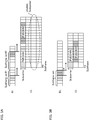
- FIG. 4A is a diagram illustrating a case in which the plurality of pieces of DCI (DCI #1 to #3) to which the repetitive transmission is not applied are included in the same subframe set
- FIG. 4B is a diagram illustrating a case in which the plurality of pieces of DCI (DCI #1 and #2) to which the repetitive transmission (in this case, the repetition number is four) is applied are included in the same subframe set.
- the UL data and/or the DL data is allocated at timing defined by the existing system.
- the existing system a case in which six pieces of DCI (in this case, UL grant) are included in one subframe set is assumed.
- the UL data PUSCHs #1 to #6 are allocated at timing after a predetermined period (for example, 4 ms) from the respective subframes to which the respective pieces of DCI (DCI #1 to #6) are allocated.
- the UL data (PUSCH #1) scheduled by the first DCI #1 that is the fastest in allocation timing and the UL data (PUSCHs #2 and #3) respectively scheduled by the second DCI #2 and the third DCI #3 are so allocated as to be partially overlapped with one another in a time region. Therefore, these UL data are so controlled as to be allocated to different subcarriers.
- the UL data (PUSCH #1) scheduled by the first DCI #1 is not overlapped with the UL data (PUSCH #4) scheduled by the fourth DCI #4 in time region. Therefore, allocation of the data is controlled with use of the same subcarrier.
- Unused resources are generated between the UL data (PUSCH #1) of the first DCI #1 and the UL data (PUSCH #4) of the fourth DCI #4.
- unused resources are generated between the UL data (PUSCH #2) of the second DCI #2 and the UL data (PUSCH #5) of the fifth DCI #5, and between the UL data (PUSCH #3) of the third DCI #3 and the UL data (PUSCH #6) of the sixth DCI #6.
- FIG. 6 is a diagram illustrating a case in which two pieces of DCI (DCI #1 and #2) to which the repetitive transmission (the repetition number is four) is applied are provided.
- the repetitive transmission it is necessary for the user terminal to control transmission of the UL data on the basis of the reception timing of the final piece of DCI (DCI transmitted in the fourth transmission) even if the user terminal can receive the DCI in the middle (in this case, the repetition number is two) of the repetitive transmission.
- the allocation positions of the uplink data (in this case, PUSCHs #1 and #2) are determined in accordance with the position of the DCI that is repeatedly transmitted in the subframe set. Therefore, it is not possible to efficiently allocate the uplink data (in this case, PUSCHs #1 and #2) depending on the position of the DCI or the repetition number, which does not result in sufficient improvement of the usage efficiency of resources.
- the usage efficiency of resources may not be sufficiently improved even when the plurality of pieces of DCI are set to one subframe set. Moreover, generation of the unused resources is increased as the number of pieces of DCI allocated to one subframe set and the frequency of repetitive transmission of the DCI are increased. This may further deteriorate the usage efficiency of resources.
- the present inventors and other persons concerned focus on the fact that using the existing transmission timing causes unused resources (resource fragment) in a time direction in allocation of the UL data when the plurality of pieces of DCI are included in the same subframe set, and have devised an idea of performing control such that transmission of the UL data scheduled by the respective pieces of DCI included in the same subframe set are started at the same timing.
- control is performed to start, at the predetermined subframe, the uplink data transmission scheduled by the respective pieces of DCI (UL grant) included in the same subframe set.
- This makes it possible to suppress generation of unused resources between different pieces of uplink data (in particular, in the time direction), thereby improving the usage efficiency of resources, even when the allocation of the uplink data is controlled while the plurality of pieces of DCI are included in the same subframe set.
- the usable band of the NB-IoT equipment is limited to 180 kHz (one PRB) which is narrower than the minimum system band (1.4 MHz) of the existing LTE system; however, the usable band of the NB-IoT equipment is not limited thereto.
- the usable band of the NB-IoT equipment may be any bandwidth, such as 1.4 MHz, that is equivalent to the minimum system band of the existing LTE system and a band narrower than 180 kHz as long as being narrower than the system band of the existing LTE system.
- a case in which the subcarrier interval is set to 15 kHz and the bandwidth of 180 kHz is configured of 12 subcarriers is exemplified below; however, the configuration is not limited thereto.
- the present embodiment is appropriately applicable to, for example, a case in which the subcarrier interval is set to 3.75 kHz and the bandwidth of 180 kHz is configured of 48 subcarriers. Note that, as described with reference to FIG. 2 , the time length of one resource unit may be varied according to the subcarrier interval.
- the resource allocation unit is regarded as "subcarrier (tone)"; however, the resource allocation unit in the present embodiment is not limited thereto, and may be any optional frequency unit as long as being smaller than the resource allocation unit (PRB) in the existing LTE system.
- PRB resource allocation unit
- a case of controlling transmission start timing of the uplink data that are scheduled by the respective pieces of downlink control information (DCI) included in the subframe set is described.
- DCI downlink control information
- a case in which the uplink data is transmitted with a single tone (a single subcarrier) is described below; however, the first aspect is applicable to a case in which the uplink data is transmitted with multiple tones (a plurality of subcarriers).
- the plurality of pieces of DCI included in one subframe set may be DCI that control scheduling of different user terminals or some or all of pieces of DCI may be DCI that controls scheduling of one user terminal.
- FIG. 7 is a diagram illustrating a case in which six pieces of DCI (DCI #1 to #6) are set in the same sub frame set and control is performed such that the transmission of the uplink data (PUSCHs #1 to #6) respectively scheduled by the six pieces of DCI are started at the same timing (allocation is started at the same position). More specifically, transmission of the UL data (PUSCHs #1 to #6) respectively scheduled by DCI #1 to #6 are started at a predetermined subframe.
- the predetermined subframe may be a subframe (for example, SF #n+k 2 ) after a predetermined period from the final subframe (for example, SF #n) of the subframe set.
- k 2 may be an integer larger than zero (for example, four).
- the radio base station includes different pieces of UL allocation information (for example, UL data resource (subcarrier)) in the respective pieces of DCI (UL grant) that are included in the same subframe, and transmits the DCI to the user terminal.
- UL allocation information for example, UL data resource (subcarrier)
- DCI UL grant
- the user terminal determines an allocation resource (subcarrier) of the UL data, on the basis of the received DCI.
- the user terminal discriminates the timing of the final subframe (SF #n) of the subframe set, on the basis of information (for example, information relating to the subframe set) that is notified through the upper layer signaling and/or the DCI.
- information relating to the timing of the final subframe of the subframe set may be the number of subframes configuring the subframe set, offset that specifies position of the subframe set, and the like.
- performing control such that the transmission of the UL data scheduled by the respective pieces of DCI included in the same subframe data are started at the same timing makes it possible to transmit the plurality of pieces of UL data with use of different subcarriers that are overlapped with one another in the time region (subframe). This makes it possible to suppress generation of unused resources between the different pieces of UL data, as compared with the case (for example, FTG. 5, FTG.6, and other drawings) in which the transmission start timing of the respective pieces of UL data are determined on the basis of the reception timing of the respective pieces of DCI (for example, the received subframe number). This allows for improvement of the usage efficiency of resources.
- FIG. 8 is a diagram illustrating a case in which two pieces of DCI (DCI #1 and #2) to which the repetitive transmission (the repetition number is four) is applied are set in the same subframe set. Furthermore, the diagram of FIG. 8 illustrates a case of performing control such that the transmission of the uplink data (for example, PUSCHs #1 and #2) respectively scheduled by the two pieces of DCI are started at the same timing.
- DCI #1 and #2 the repetitive transmission
- control is performed to start, at a predetermined subframe, transmission of the UL data (PUSCHs #1 and #2) respectively scheduled by the DCI #1 and #2.
- the predetermined subframe may be a subframe (for example, SF #n+k 2 ) after a predetermined period from the final subframe (for example, SF #n) of the subframe set.
- k 2 may be a value larger than zero (for example, four).
- the user terminal determines an allocation resource (subcarrier) of the UL data on the basis of the received DCI, and starts the UL data transmission at the predetermined subframe.
- the frequency of repetitive transmission applied to the uplink data that are respectively scheduled by different pieces of DCI in the same subframe set may be the same or may be different between the uplink data.
- the predetermined subframe that becomes the transmission start timing of the UL data is determined on the basis of the final subframe of the subframe set is illustrated in FIG. 7 and FIG. 8 ; however, the present embodiment is not limited thereto.
- the predetermined subframe may be determined on the basis of the subframe in which the final piece of DCI (downlink control channel) included in the subframe set is transmitted.
- the final piece of DCI only the DCI (UL grant) that schedules the UL transmission may be considered, or both of the DCI that schedules the UL transmission and the DCI (DL assignment) that schedules the DL transmission may be considered.
- FIG. 9 and FIG. 10 are diagrams each illustrating the case in which the start timing of the UL transmission is determined on the basis of the subframe in which the final piece of DCI (the DCI #6) out of the plurality of pieces of DCI (DCI #1 to #6) included in the subframe set is transmitted. Note that the diagram of FIG. 9 illustrates the case of not using the repetitive transmission (normal coverage case) and the diagram of FIG. 10 illustrates the case of applying the repetitive transmission (enhanced coverage case).
- the radio base station informs the user terminal of information relating to the subframe (SF #m) in which the final piece of DCI (DCI #6) included in the subframe set is transmitted, by including the information in the DCI (for example, DCI #1 to #6).
- the user terminal discriminates, on the basis of the information included in the DCI, a subframe (for example, SF #m) in which the DCI #6 is transmitted, and starts the UL transmission at a subframe (for example, SF #m+k 2 ) after a predetermined period from the subframe in which the DCI #6 is transmitted.
- k 2 may be a value larger than zero (for example, four).
- the radio base station may include, in the DCT, information relating to the predetermined subframe that becomes the start timing of the UL transmission, thereby notifying the user terminal of the information.
- the information relating to the predetermined subframe may be, for example, a predetermined subframe number itself or a subframe that is a reference to determine the predetermined subframe as long as the information helps to determine the predetermined subframe.
- the radio base station includes the information relating to the predetermined subframe in the respective pieces of DCI that are transmitted in the same subframe set, thereby transmitting the information to the user terminal.
- a case of controlling reception start timing of the downlink data that are scheduled by the respective pieces of DCI included in the subframe set is described. Note that a case in which the downlink data is transmitted with multiple tones (a plurality of subcarriers (for example, one PRB)) is described below; however, the second aspect is applicable to a case in which the downlink data is transmitted with a single tone (a single subcarrier).
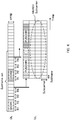
- FIG. 11A is a diagram illustrating a case of setting seven pieces of DCI (DCI #1 to #7) in one subframe set.
- DCI #1 to #6 a case in which the uplink data are scheduled by six pieces of DCI (DCI #1 to #6) and the downlink data is scheduled by one piece of DCI (DCI #7) is assumed.
- the DCI #1 to #6 correspond to UL grant
- the DCI #7 corresponds to DL assignment.
- the number of pieces of DCI for downlink scheduling and the number of pieces of DCI for uplink scheduling are not limited thereto.
- only one DL assignment may be included in one subframe set. In this case, it is possible to simplify allocation control when the DL data is transmitted with multiple carriers. Alternatively, a plurality of DL assignment may be included in one subframe set.
- the user terminal starts reception of the DL data (PDSCH) scheduled by the DCI #7, at a predetermined subframe.
- the predetermined subframe may be a subframe (for example, SF #n+k 1 ) after predetermined period from the final subframe (for example, SF #n) of the subframe set.
- k 1 may be an integer larger than zero (for example, one). Note that the above-described first aspect is applicable to the transmission of the UL data (PUSCHs #1 to #6) that are respectively scheduled by the DCI #1 to #6.
- the radio base station includes DL allocation information (for example, a resource for DL data (a subcarrier)) in the DCI (DL assignment) included in the subframe set, thereby transmitting the DL allocation information to the user terminal.
- the user terminal starts to receive the DL data at the predetermined subframe, irrespective of the subframe number in which the received DCI is included.
- the user terminal determines an allocation resource (subcarrier) of the DL data, on the basis of the received DCI.
- the user terminal discriminates the timing of the final subframe (SF #n) of the subframe set, on the basis of information (for example, information relating to the subframe set) that is notified through the upper layer signaling and/or the DCI.
- FIG. 11B is a diagram illustrating a case in which two pieces of DCI (DCI #1 and #2) to which the repetitive transmission (the repetition number is four) is applied are set in the same subframe set.
- DCI #1 and #2 the repetitive transmission
- the DCI #1 and the uplink data are scheduled by the DCI #2.
- the DCI #1 corresponds to DL assignment
- the DCI #2 corresponds to UL grant.
- the user terminal starts the reception of the DL data (PDSCH) that is scheduled by the DCI #1, at a predetermined subframe.
- the predetermined subframe may be a subframe (for example, SF #n+k 1 ) after the predetermined period from the final subframe (for example, SF #n) of the subframe set.
- the reception start timing of the DL data that is scheduled by the DCI included in the subframe set is determined based not on the reception timing of the DCI (the reception subframe) but on the final subframe configuring the subframe set.
- determining the reception timing on the basis of the final subframe of the subframe set makes it possible to suppress generation of unused resources after the subframe set, which allows for efficient use of resources.
- the predetermined subframe that becomes the reception start timing of the DL data is determined on the basis of the final subframe of the subframe set is illustrated in FIG. 11 ; however, the present embodiment is not limited thereto.
- the predetermined subframe may be determined on the basis of the subframe in which the final piece of DCI (the downlink control channel) included in the subframe set is transmitted.
- FIGs. 12A and 12B are diagrams each illustrating the case in which the reception start timing of the DL data is determined on the basis of the subframe in which the final piece (DCI #6 in FIG. 12A and DCI #2 in FIG. 12B ) of the DCI (the DCI #1 to #7 in FIG. 12A and DCI #1 and #2 in FIG. 12B ) included in the subframe set, is transmitted.
- the diagram of FIG. 12A illustrates the case of not using the repetitive transmission (the normal coverage case)
- the diagram of FIG. 12B illustrates the case of applying the repetitive transmission (the enhanced coverage case).
- the radio base station includes, in the DCI (for example, DCI #1 to #6 in FIG. 12A ), the information relating to the subframe (SF #m) in which the final piece of DCI included in the subframe set is transmitted, thereby notifying the user terminal of the information.
- the user terminal discriminates the subframe (for example, SF #m) in which the final piece of DCI is transmitted, on the basis of the information included in the DCI, and starts the UL transmission at a subframe (for example, SF #m+k 1 ) after the predetermined period from the subframe in which the final piece of DCI is transmitted.
- k 1 may be a value larger than zero (for example, one).
- controlling the reception start timing of the DL data that are scheduled by the respective pieces of DCI included in the subframe set makes it possible to suppress collision of the DCI included in the subframe set with the DL data. Moreover, it is possible to start the allocation of the DL data that are respectively scheduled by the DL assignment at the same position when the plurality of DL assignment are included in the subframe set. This makes it possible to suppress generation of unused resources and to improve the usage efficiency of resources.
- Determining the reception start timing of the DL data on the basis of the transmission timing of the final piece of DCI included in the subframe set makes it possible to advance the reception (DL assignment) start timing of the DL data, as compared with the reception start timing in FIG. 11 . As a result, it is possible to further improve the usage efficiency of resources and to reduce delay.
- the radio base station may include the information relating to the predetermined subframe that becomes the start timing of the DL transmission in the DCI and inform the user terminal of the information.
- the information relating to the predetermined subframe may be, for example, the predetermined subframe number itself or a subframe that is a reference to determine the predetermined subframe as long as the information helps to determine the predetermined subframe.
- the radio base station includes the information relating to the predetermined subframe in the respective pieces of DCI that are transmitted in the same subframe set, and transmits the DCI to the user terminal.
- the radio communication method according to any of the above-described aspects is applied. Note that the radio communication methods according to the respective aspects may be used singularly or in combination.
- the NB-IoT equipment is exemplified here as a user terminal, a usable band of which is limited to the narrow band, the user terminal is not limited thereto.
- FIG. 13 is a schematic configuration diagram of the radio communication system according to the embodiment of the present invention.
- a radio communication system 1 illustrated in FIG. 13 is an example of a radio communication system in which the LTE system is adopted as a network domain of a machine communication system.
- carrier aggregation (CA) and/or duel connectivity (DC) in which a plurality of basic frequency blocks (component carriers) are aggregated is applied.
- Each of the basic frequency blocks uses the system bandwidth of the LTE system as one unit.
- the system band of the LTE system is set to a range from 1.4 MHz at a minimum up to 20 MHz at a maximum in both downlink and uplink; however, the system is not limited thereto.
- radio communication system 1 may be also referred to as, for example, SUPER 3G, LTE-Advanced (LTE-A), IMT-Advanced, 4th generation mobile communication system (4G), 5th generation mobile communication system (5G), or future radio access (FRA).
- LTE-A LTE-Advanced
- IMT-Advanced 4th generation mobile communication system
- 4G 4th generation mobile communication system
- 5G 5th generation mobile communication system
- FAA future radio access
- the radio communication system 1 includes a radio base station 10 and a plurality of user terminals 20A, 20B, and 20C that are wirelessly connected to the radio base station 10.
- the radio base station 10 is connected to a host station device 30, and is connected to a core network 40 through the host station device 30.
- the host station device 30 may include, for example, an access gateway device, a radio network controller (RNC), and a mobility management entity (MME) without limitation.
- RNC radio network controller
- MME mobility management entity
- the plurality of user terminals 20 (20A to 20C) each communicate with the radio base station 10 in a cell 50.
- the user terminal 20A is a user terminal that supports the LTE (up to Rel.10) or the LTE-Advanced (including Rel.10 and subsequent releases) (hereinafter, referred to as LTE user equipment (LTE UE)).
- LTE UE LTE user equipment
- Each of the user terminals 20B and 20C is NB-IoT user equipment (NB-IoT UE) serving as a communication device in machine communication system.
- NB-IoT UE NB-IoT user equipment
- the user terminals 20A, 20B, and 20C are simply referred to as the user terminal 20.
- the user terminal 20 may be also referred to as, for example, user equipment (UE).
- UE user equipment
- Each of the NB-IoT UE 20B and 20C is a user terminal, the usable band of which is limited to a bandwidth narrower than the minimum system bandwidth that is supported by the existing LTE system.
- each of the NB-IoT UE 20B and 20C may be a terminal corresponding to various kinds of communication systems such as LTE and LTE-A, and may be a mobile communication terminal of a vehicle or the like without being limited to a stationary communication terminal such as an electricity meter, a gas meter, and an automatic vending machine.
- the user terminal 20 may communicate with the other user terminal 20 directly or through the radio base station 10.
- orthogonal frequency division multiple access OFDMA
- SC-FDMA single-carrier frequency division multiple access
- the OFDMA is a multicarrier transmission system in which a frequency band is divided into a plurality of narrow frequency bands (subcarriers) and data are mapped to the respective subcarriers to perform communication.
- the SC-FDMA is a single-carrier transmission system in which a system bandwidth is divided into bands each configured of one resource block or successive resource blocks, for each terminal, and a plurality of terminals use the bands different from one another to reduce interference between terminals. Note that the radio access systems in the uplink and the downlink are not limited to these combinations.
- a physical downlink shared channel that is shared between the user terminals 20, a physical broadcast channel (PBCH), and a downlink L1/L2 control channel are used as the downlink channel.
- PBCH physical broadcast channel
- SIB system information block
- MIB master information block
- the downlink L1/L2 control channel includes, for example, a physical downlink control channel (PDCCH), an enhanced physical downlink control channel (EPDCCH), a physical control format indicator channel (PCFICH), and a physical hybrid-ARQ indicator channel (PHICH).
- the downlink control information (DCI) including scheduling information of the PDSCH and the PUSCH and other information is transmitted through the PDCCH.
- the number of OFDM symbols used in the PDCCH is transmitted through the PCFICH.
- the hybrid automatic repeat request acknowledge (HARQ-ACK) of the PUSCH is transmitted through the PHICH.
- the EPDCCH is frequency-division multiplexed with the PDSCH, and is used for transmission of the DCI or other information, as with the PDCCH.
- a physical uplink shared channel that is shared between the user terminals 20, a physical uplink control channel (PUCCH), and a physical random access channel (PRACH) are used as the uplink channel.
- the PUSCH may be also referred to as an uplink data channel.
- User data and upper layer control information are transmitted through the PUSCH.
- a channel quality indicator (CQI) of the downlink and the hybrid automatic repeat request acknowledge (HARQ-ACK) are transmitted through the PUCCH.
- a random access preamble to establish connection with the cell is transmitted through the PRACH.
- the channel for the MTC UE may be represented with "M” indicating MTC
- the channel for the NB-IoT UE may be represented with "NB” indicating NB-IoT.
- PDCCH/EPDCCH, PDSCH, PUCCH, PUSCH for the MTC UE (the NB-IoT UE) may be respectively referred to as M(NB)-PDCCH, M(NB)-PDSCH, M(NB)-PUCCH, and M(NB)-PUSCH.
- PDCCH, PDSCH, PUCCH, and PUSCH are simply referred to as PDCCH, PDSCH, PUCCH, and PUSCH.
- a cell-specific reference signal CRS
- CST-RS channel state information-reference signal
- DMRS demodulation reference signal
- PRS positioning reference signal
- SRS sounding reference signal
- DMRS demodulation reference signal
- PRS positioning reference signal
- SRS sounding reference signal
- DMRS demodulation reference signal
- PRS positioning reference signal
- the DMRS may be also referred to as a UE-specific reference signal.
- the reference signal to be transmitted is not limited to these signals.
- FIG. 14 is a diagram illustrating an example of an entire configuration of the radio base station according to the embodiment of the present invention.
- the radio base station 10 at least includes: a plurality of transmission/reception antennass 101; a plurality of amplifier units 102; a plurality of transmission/reception units (transmission/reception sections) 103; a baseband signal processing unit (baseband signal processing section) 104; a call processing unit (call processing section) 105; and a transmission line interface 106.
- the user data that is transmitted from the radio base station 10 to the user terminal 20 through the downlink is provided from the host station device 30 to the baseband signal processing unit 104 through the transmission line interface 106.
- the baseband signal processing unit 104 performs, on the user data, packet data convergence protocol (PDCP) layer processing, division and coupling of the user data, radio link control (RLC) layer transmission processing such as RLC retransmission control, medium access control (MAC) retransmission control (for example, transmission processing of hybrid automatic repeat request (HARQ)), scheduling, transmission format selection, channel encoding, inverse fast Fourier transform (IFFT) processing, and precoding processing, and the processed user data is then transferred to each of the transmission/reception units 103.
- RLC radio link control
- MAC medium access control
- MAC medium access control
- IFFT inverse fast Fourier transform
- precoding processing for example, transmission processing of hybrid automatic repeat request (HARQ)
- HARQ hybrid automatic repeat request
- transmission processing such as the channel encoding and the inverse fast Fourier transform is performed on the downlink control signal, and the processed signal is then transferred to each of the transmission/reception units 103.
- Each of the transmission/reception units 103 converts the baseband signal that has been precoded for each antenna and provided from the baseband signal processing unit 104, into a signal of a radio frequency band, thereby transmitting the converted signal.
- Each of the transmission/reception unit 103 may be configured of a transmitter/receiver, a transmission/reception circuit, or a transmission/reception device that is described under common recognition in the technical field according to the present invention. Note that each of the transmission/reception units 103 may be configured as an integral transmission/reception unit or may be configured of a transmission unit and a reception unit.
- the signal in the radio frequency band that has been converted in frequency by each of the transmission/reception units 103 is amplified by the corresponding amplifier unit 102, and the amplified signal is transmitted from the corresponding transmission/reception antenna 101.
- Each of the transmission/reception units 103 transmits and receives various kinds of signals with a narrow bandwidth (for example, 180 kHz) that is limited narrower than the system bandwidth (for example, one component carrier).
- the uplink signal the signal in radio frequency band that has been received by each of the transmission/reception antennae 101 is amplified by the corresponding amplifier unit 102.
- Each of the transmission/reception units 103 receives the uplink signal that has been amplified by the corresponding amplifier unit 102.
- Each of the transmission/reception units 103 converts, in frequency, the received signal into a baseband signal, and provides the baseband signal to the baseband signal processing unit 104.
- the baseband signal processing unit 104 performs, on the user data included in the provided uplink signals, fast Fourier transform (FFT) processing, inverse discrete Fourier transform (IDFT) processing, error correction decoding, reception processing of MAC retransmission control, and reception processing of RLC layer and PDCP layer, and the processed signals are transferred to the host station device 30 through the transmission line interface 106.
- the call processing unit 105 performs call processing such as setting and releasing of the communication channel, state management of the radio base station 10, and management of radio resources.
- the transmission line interface 106 transmits and receives a signal to and from the host station device 30 through a predetermined interface. Further, the transmission line interface 106 may transmit and receive a signal (perform backhaul signaling) to and from the other radio base station 10 through an inter-eNB interface (such as an optical fiber compliant with common public radio interface (CPRI) and X2 interface).
- an inter-eNB interface such as an optical fiber compliant with common public radio interface (CPRI) and X2 interface.
- Each of the transmission/reception units (the transmission units) 103 transmits the downlink control information with use of the subframe set that is set for the downlink control channel in a predetermined bandwidth.
- Each of the transmission/reception units (the reception units) 103 receives the uplink data that is transmitted from the user terminal, on the basis of the downlink control information. Further, each of the transmission/reception units (the reception units) 103 may start to receive the uplink data that are scheduled by the respective pieces of downlink control information transmitted in the same subframe set, at a predetermined subframe.
- FIG. 15 is a diagram illustrating an example of a functional configuration of the radio base station according to the embodiment of the present invention. Note that, in FIG. 15 , distinctive functional blocks in the present embodiment are mainly illustrated, and the radio base station 10 may further include other functional blocks necessary for the radio communication. As illustrated in FIG. 15 , the baseband signal processing unit 104 at least includes: a control unit (control section) 301; a transmission signal generation unit (a generation unit) 302; a mapping unit 303; a reception signal processing unit 304; and a measurement unit 305.
- the control unit 301 controls the entire radio base station 10.
- the control unit 301 may be configured of a controller, a control circuit, or a control device that is described under common recognition in the technical field according to the present invention.
- control unit 301 controls signal generation by the transmission signal generation unit 302 and signal allocation by the mapping unit 303. Further, the control unit 301 controls reception processing of a signal by the reception signal processing unit 302 and measurement of a signal by the measurement unit 305. Furthermore, the control unit 301 controls resource allocation (scheduling) of system information, PDSCH, and PUSCH. In addition, the control unit 301 controls resource allocation of the downlink reference signal such as a synchronization signal (for example, primary synchronization signal (PSS)/secondary synchronization signal (SSS), and an NB-SS), a CRS, a CSI-RS, and a DM-RS.
- a synchronization signal for example, primary synchronization signal (PSS)/secondary synchronization signal (SSS), and an NB-SS
- CRS channel synchronization reference signal
- CSI-RS CSI-RS
- DM-RS DM-RS
- the control unit 301 controls the transmission signal generation unit 302 and the mapping unit 303 to allocate the various types of signals to the narrow band and to transmit the various types of signals to the user terminals 20.
- the control unit 301 performs control to transmit, for example, the downlink broadcast information (MIB, SIB (MTC-SIB)), PDCCH (also referred to as, for example, M-PDCCH or NB-PDCCH), and PDSCH, in the narrow band.
- the narrow band (NB) is a band (for example, 180 kHz) narrower than the system band of the existing LTE system.
- the control unit 301 receives the PUSCH with use of the determined PUSCH resource, in cooperation with the transmission/reception units 103, the reception signal processing unit 302, and the measurement unit 305. Moreover, the control unit 301 transmits the PDSCH with use of the determined PDSCH resource, in cooperation with the transmission signal generation unit 302, the mapping unit 303, and the transmission/reception units 103.
- the transmission signal generation unit (the generation unit) 302 generates the downlink signal (such as the PDCCH, the PDSCH, and the downlink reference signal), in response to instruction from the control unit 301, and provides the generated downlink signal to the mapping unit 303.
- the transmission signal generation unit 302 may be configured of a signal generator, a signal generation circuit, or a signal generation device that is described under common recognition in the technical field according to the present invention.
- the transmission signal generation unit 302 generates, for example, in response to instruction from the control unit 301, DCI (also referred to as, for example, DL assignment or UL grant) that allocates the PUSCH and/or the PDSCH to the user terminals 20.
- DCI also referred to as, for example, DL assignment or UL grant
- encoding processing and modulation processing are performed on the PDSCH, in accordance with, for example, an encoding rate and modulation method that are determined on the basis of the channel state information (CSI) or other information from the respective user terminals 20.
- CSI channel state information
- the mapping unit 303 maps the downlink signal generated in the transmission signal generation unit 302, to the radio resource (for example, one resource block at a maximum) of the predetermined narrow band, in response to instruction from the control unit 301, and provides the downlink signal to the transmission reception units 103.
- the mapping unit 303 may be configured of a mapper, a mapping circuit, or a mapping device that is described under common recognition in the technical field according to the present invention.
- the reception signal processing unit 304 performs reception processing (such as demapping, demodulation, and decoding) on the reception signal provided from each of the transmission/reception units 103.
- the reception signal may be, for example, the uplink signal (such as the PUCCH, the PUSCH, and the uplink reference signal) transmitted from the user terminals 20.
- the reception signal processing unit 304 may be configured of a signal processor, a signal processing circuit, or a signal processing device that is described under common recognition in the technical field according to the present invention.
- the reception signal processing unit 304 provides information decoded through the reception processing, to the control unit 301. In addition, the reception signal processing unit 304 provides the reception signal and the reception-processed signal to the measurement unit 305.
- the measurement unit 305 performs measurement relating to the received signal.
- the measurement unit 305 may be configured of a measurement instrument, a measurement circuit, or a measurement device that is described under common recognition in the technical field according to the present invention.
- the measurement unit 305 may measure, for example, reception power of the signal (for example, reference signal received power (RSRP)), reception quality of the signal (for example, reference signal received quality (RSRQ)), and the channel state.
- RSRP reference signal received power
- RSS reference signal received quality
- a measurement result may be provided to the control unit 301.
- FIG. 16 is a diagram illustrating an example of an entire configuration of the user terminal according to the embodiment of the present invention.
- the user terminal 20 at least includes: a transmission/reception antenna 201; an amplifier unit 202; a transmission/reception unit 203; a baseband signal processing unit 204; and an application unit 205.
- the user terminal 20 may include, for example, a plurality of transmission/reception antennas 201, a plurality of amplifier units 202, and a plurality of transmission/reception units (transmission/reception section) 203.
- the radio frequency signal received by the transmission/reception antenna 201 is amplified by the amplifier unit 202.
- the transmission/reception unit 203 receives the downlink signal amplified by the amplifier unit 202.
- the transmission reception unit 203 performs frequency conversion on the reception signal to convert the reception signal into the baseband signal, and provides the baseband signal to the baseband signal processing unit 204.
- the transmission/reception unit 203 may be configured of a transmitter/receiver, a transmission/reception circuit, or a transmission/reception device that is described under common recognition in the technical field according to the present invention. Note that the transmission/reception unit 203 may be configured as an integral transmission/reception unit or may be configured of a transmission unit and a reception unit.
- the baseband signal processing unit 204 performs FFT processing, error correction decoding, reception processing of retransmission control, and other processing on the provided baseband signal.
- the downlink user data is transferred to the application unit 205.
- the application unit 205 performs processing relating to a layer upper than the physical layer and the MAC layer.
- the broadcast information of the downlink data is also transferred to the application unit 205.
- the uplink user data is provided from the application unit 205 to the baseband signal processing unit 204.
- the baseband signal processing unit 204 performs transmission processing of the hybrid automatic repeat request acknowledge (HARQ-ACK), channel encoding, precoding, discrete Fourier transform (DFT) processing, IFFT processing, and other processing, on the uplink user data, and the processed data is transferred to the transmission/reception unit 203.
- HARQ-ACK hybrid automatic repeat request acknowledge
- DFT discrete Fourier transform
- IFFT processing IFFT processing
- the transmission/reception unit 203 converts the baseband signal provided from the baseband signal processing unit 204, into a signal of the radio frequency band, and transmits the signal of the radio frequency band.
- the radio frequency signal converted in frequency by the transmission/reception unit 203 is amplified by the amplifier unit 202, and the amplified signal is transmitted from the transmission/reception antenna 201.
- the transmission/reception unit (the reception unit) 203 receives the downlink control information included in the sub frame set that is set for the downlink control channel in a predetermined bandwidth. Moreover, the transmission/reception unit (the reception unit) 203 receives the downlink control information including information relating to the final sub frame to which the downlink control channel is allocated in the subframe set. Furthermore, the transmission/reception unit (the reception unit) 203 receives information relating to the subframe set.
- FIG. 17 is a diagram illustrating an example of a functional configuration of the user terminal according to the embodiment of the present invention. Note that, in FIG. 17 , distinctive functional blocks in the present embodiment are mainly illustrated, and the user terminal 20 may further include other functional blocks necessary for the radio communication. As illustrated in FTG. 17, the baseband signal processing unit 204 included in the user terminal 20 at least includes: a control unit (control section) 401; a transmission signal generation unit (a generation unit) 402; a mapping unit 403; a reception signal processing unit 404; and a measurement unit 405.
- the control unit 401 controls the entire user terminal 20.
- the control unit 401 may be configured of a controller, a control circuit, or a control device that is described under common recognition in the technical field according to the present invention.
- control unit 401 controls signal generation by the transmission signal generation unit 402 and signal allocation by the mapping unit 403.
- control unit 401 controls signal reception processing by the reception signal processing unit 404 and signal measurement by the measurement unit 405.
- the control unit 401 acquires, from the reception signal processing unit 404, the downlink signal (such as the PDCCH, the PDSCH, and the downlink reference signal) transmitted from the radio base station 10.
- the control unit 401 controls generation of the uplink control information (UCI) such as the hybrid automatic repeat request acknowledge (HARQ-ACK) and the channel state information (CSI) and generation of the uplink data, on the basis of the downlink signal.
- UCI uplink control information
- HARQ-ACK hybrid automatic repeat request acknowledge
- CSI channel state information
- the control unit 401 controls the uplink data transmission, on the basis of the downlink control information. For example, the control unit 401 performs control to start the uplink data transmission that are scheduled by the respective pieces of downlink control information included in the same subframe set, at a predetermined subframe. More specifically, the control unit 401 starts the uplink data transmission that is scheduled by the respective pieces of downlink control information included in the same subframe set, at a subframe after a predetermined period from the final subframe of the subframe set (refer to FIG. 7 and FIG. 8 ).
- the control unit 401 starts the uplink data transmission that is scheduled by the respective pieces of downlink control information included in the same subframe set, at a subframe after a predetermined period from the final subframe to which the downlink control channel is allocated, of the subframe set (refer to FIG. 9 and FIG. 10 ).
- the control unit 401 repeatedly performs the uplink data transmission that is scheduled by the respective pieces of downlink control information included in the same subframe set, at a predetermined subframe. Moreover, the control unit 401 performs control to perform the uplink data transmission that is scheduled by the respective pieces of downlink control information included in the same subframe set, with use of the single carrier. Note that the uplink data scheduled by the downlink control information included in the subframe set may be allocated to different subcarriers in the same PRB.
- the control unit 401 performs control to start the downlink data reception that is scheduled by the downlink control information included in the subframe set, at a predetermined subframe (refer to FIG. 11 and FIG. 12 ).
- the control unit 401 transmits the PUSCH with use of the PUSCH resource, in cooperation with the transmission signal generation unit 402, the mapping unit 403, and the transmission/reception unit 203. Furthermore, the control unit 401 receives the PDSCH with use of the PDSCH resource, in cooperation with the transmission/reception unit 203, the reception signal processing unit 404, and the measurement unit 405.
- the transmission signal generation unit 402 generates the uplink signal (such as the PUCCH, the PUSCH, and the uplink reference signal), on the basis of instruction from the control unit 401, and provides the generated uplink signal to the mapping unit 403.
- the transmission signal generation unit 402 may be configured of a signal generator, a signal generation circuit, or a signal generation device that is described under common recognition in the technical field according to the present invention.
- the transmission signal generation unit 402 generates, for example, in response to instruction from the control unit 401, the uplink control information (UCI) and/or the uplink data. In addition, the transmission signal generation unit 402 generates, in response to instruction from the control unit 401, the PUSCH through which the UCT and/or the uplink data is transmitted. For example, when the user terminal 20 receives the DCI to which the PUSCH is allocated, the transmission signal generation unit 402 receives instruction of PUSCH generation from the control unit 401. Further, the transmission signal generation unit 402 generates, in response to instruction from the control unit 401, the PUCCH through which the UCI is transmitted.
- the control unit 401 the uplink control information
- the mapping unit 403 maps the uplink signal generated in the transmission signal generation unit 402 to the resource (for example, the PUSCH resource and the PUCCH resource) in response to instruction from the control unit 401, and provides the uplink signal to the transmission/reception unit 203.
- the mapping unit 403 may be configured of a mapper, a mapping circuit, or a mapping device that is described under common recognition in the technical field according to the present invention.
- the reception signal processing unit 404 performs reception processing (such as demapping, demodulation, and decoding) on the reception signal provided from the transmission/reception unit 203.
- the reception signal may be, for example, the downlink signal (such as the downlink control signal, the downlink data signal, and the downlink reference signal) transmitted from the radio base station 10.
- the reception signal processing unit 404 may be configured of a signal processor, a signal processing circuit, or a signal processing device that is described under common recognition in the technical field according to the present invention.
- the reception signal processing unit 404 provides information decoded through the reception processing, to the control unit 401.
- the reception signal processing unit 404 provides, for example, the broadcast information, the system information, the RRC signaling, and the DCI, to the control unit 401.
- the reception signal processing unit 404 provides the reception signal and the reception-processed signal, to the measurement unit 405.
- the measurement unit 405 performs measurement relating to the received signal.
- the measurement unit 405 may be configured of a measurement instrument, a measurement circuit, or a measurement device that is described under common recognition in the technical field according to the present invention.
- the measurement unit 405 may measure, for example, reception power of the received signal (for example, RSRP), reception quality of the received signal (for example, RSRQ), and the channel state. A measurement result may be provided to the control unit 401.
- reception power of the received signal for example, RSRP
- reception quality of the received signal for example, RSRQ
- the block diagrams used in the above-described description of the embodiments each illustrate blocks of a functional unit.
- the functional blocks (components) are realized by optional combination of hardware and/or software.
- the respective functional blocks may be realized in an optional manner without particular limitation.
- the functional blocks may be realized by one device physically coupled, or may be realized by two or more devices that are physically separated from one another but are connected to one another through wired or radio connection.
- the radio base station and the user terminal according to the embodiment of the present invention may function as a computer that performs processing of the radio communication method according to the present invention.
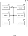
- FIG. 18 is a diagram illustrating an example of a hardware configuration of the radio base station and the user terminal according to the embodiment of the present invention.
- the radio base station 10 and the user terminal 20 mentioned above may be physically configured as a computer apparatus that includes a processor 1001, a memory 1002, a storage 1003, a communication device 1004, an input device 1005, an output device 1006, a bus 1007, and other components.
- the term “device” may be replaced with, for example, a circuit, an apparatus, or a unit.
- the hardware configuration of the radio base station 10 and the user terminal 20 may include one or a plurality of the respective illustrated devices, or may not include a portion of devices.
- the respective functions of the radio base station 10 and the user terminal 20 are realized by loading predetermined software (program) to hardware such as the processor 1001 and the memory 1002 to cause the processor 1001 to execute arithmetic, and controlling communication by the communication device 1004 and reading and/or writing of data in the memory 1002 and the storage 1003.
- predetermined software program
- the processor 1001 operates an operating system to control the entire computer.
- the processor 1001 may be configured of a central processing unit (CPU) that includes, for example, an interface with peripheral apparatuses, a control device, an arithmetic device, and a register.
- CPU central processing unit
- the baseband signal processing unit 104 (204) and the call processing unit 105 mentioned above may be realized by the processor 1001.
- the processor 1001 loads programs (program codes), software modules, and data from the storage 1003 and/or the communication device 1004 to the memory 1002, thereby executing various types of processes according thereto.
- programs program codes
- software modules software modules
- data data from the storage 1003 and/or the communication device 1004
- the program a program that causes the computer to execute at least a portion of operations described in the above-described embodiment, is used.
- the control unit 401 of the user terminal 20 may be realized by a control program that is held by the memory 1002 and operated by the processor 1001, and other functional blocks may be similarly realized.
- the memory 1002 is a computer-readable recording medium that is configured of one or more of, for example, a read-only memory (ROM), an erasable programmable ROM (EPROM), and a random access memory (RAM).
- the memory 1002 may be referred to as, for example, a register, a cache, or a main memory (a main memory device).
- the memory 1002 holds, for example, programs (program codes) and software modules that are executable to implement the radio communication method according to the embodiment of the present invention.
- the storage 1003 is a computer-readable recording medium that is configured of one or more of, for example, an optical disc such as a compact disc ROM (CD-ROM), a hard disk drive, a flexible disk, a magneto-optical disk, and a flash memory.
- the storage 1003 may be referred to as an auxiliary memory device.
- the communication device 1004 is hardware (a transmission/reception device) that performs communication between computers through a wired and/or radio network, and is also referred to as, for example, a network device, a network controller, a network card, or a communication module.
- a network device a network controller, a network card, or a communication module.
- the transmission/reception antenna 101 (201), the amplifier unit 102 (202), the transmission/reception unit 103 (203), and the transmission line interface 106 may be each realized by the communication device 1004.
- the input device 1005 is an input device (such as a keyboard and a mouse) that receives input from outside.
- the output device 1006 is an output device (such as a display and a speaker) that executes output to the outside. Note that the input device 1005 and the output device 1006 may be integrally configured (for example, a touch panel).
- the devices such as the processor 1001 and the memory 1002 are connected to one another through the bus 1007 for information communication.
- the bus 1007 may be configured of a single bus or buses different between devices.
- the radio base station 10 and the user terminal 20 may include hardware such as a microprocessor, a digital signal processor (DSP), an application specific integrated circuit (ASIC), a programmable logic device (PLD), and a field programmable gate array (FPGA), and a portion or all of the functional blocks may be realized by the hardware.
- the processor 1001 may be implemented by at least one hardware.
- the channel and/or the symbol may be a signal (signaling). Further, the signal may be a message.
- the component carrier (CC) may be referred to as, for example, a cell, a frequency carrier, or a carrier frequency.
- the radio frame may be configured of one or a plurality of periods (frames) in a time region.
- the one or the plurality of periods (frames) configuring the radio frame may be each referred to as a subframe.
- the subframe may be configured of one or a plurality of slots in the time region.
- the slot may be configured of one or a plurality of symbols (such as OFDM symbols and SC-FDMA symbols) in the time region.
- the radio frame, the subframe, the slot, and the symbol all represent a time unit in transmission of the signal.
- Other names respectively corresponding to the radio frame, the subframe, the slot, and the symbol may be used.
- one subframe may be referred to as a transmission time interval (TTI)
- TTI transmission time interval
- a plurality of successive subframes may be referred to as the TTI
- one slot may be referred to as the TTI.
- the subframe and the TTI may be a subframe (1 ms) in the existing LTE, may be a period shorter than 1 ms (for example, 1 to 13 symbols), or a period longer than 1 ms.
- the TTI indicates, for example, a minimum time unit of scheduling in the radio communication.
- the radio base station performs scheduling to allocate the radio resources (for example, a frequency bandwidth, a transmission power, and the like that are usable in each user terminal) to the user terminals by the TTI unit.
- the definition of the TTI is not limited thereto.
- the TTI having a time length of 1 ms may be referred to as, for example, a typical TTI (TTI in LTE Rel.8 to 12), a normal TTI, a long TTI, a typical subframe, a normal subframe, or a long subframe.
- the TTI shorter than the typical TTI may be referred to as, for example, a shortened TTI, a short TTI, a shortened subframe, or a short subframe.
- the resource block is a resource allocation unit in the time region and the frequency region.
- the resource block may include one or a plurality of successive subcarriers in the frequency region.
- the RB may include, in the time region, one or a plurality of symbols and may have a length of one slot, one subframe, or one TTI.
- One TTI and one subframe may be each configured of one or a plurality of resource blocks.
- the RB may be referred to as, for example, a physical RB (PRB), a PRB pair, or a RB pair.
- the resource block may be configured of one or a plurality of resource elements (REs).
- REs resource elements
- one RE may be a radio resource region of one subcarrier or one symbol.
- the configurations of the radio frame, the subframe, the slot, and the symbol described above are merely exemplified.
- the number of subframes included in the radio frame, the number of slots included in the subframe, the number of symbols and RBs included in the slot, the number of subcarriers included in the RB, the number of symbols in the TTI, the symbol length, and the cyclic prefix (CP) length may be variously varied.
- the information, the parameters, and the like described in the present specification may be represented by an absolute value, a relative value from a predetermined value, or corresponding different information.
- the radio resource may be indicated by a predetermined index.
- the data, the instruction, the command, the information, the signal, the bit, the symbol, and the chip that are mentioned over the above-described entire description may be represented by a voltage, a current, an electromagnetic wave, a magnetic field or a magnetic particle, an optical field or a photon, or any combination thereof.
- the software, the instruction, the information, and the like may be transmitted and received through a transmission medium.
- a transmission medium such as a coaxial cable, an optical fiber cable, a twist pair, or a digital subscriber line (DSL)
- a radio technology such as infrared rays or microwaves
- the wired technology and/or the radio technology are encompassed in the definition of the transmission medium.
- the radio base station in the present specification may be replaced with the user terminal.
- the respective aspects/embodiment of the present invention may be applied to a configuration in which communication between the radio base station and the user terminal is replaced with device-to-device (D2D) communication.
- the user terminal 20 may include the above-described functions of the radio base station 10.
- the terms of "uplink” and "downlink” may be replaced with "side”.
- the uplink channel may be replaced with a side channel.
- the user terminal in the present specification may be replaced with the radio base station.
- the radio base station may include the above-described functions of the user terminal 20.
- Notification of predetermined information is not limited to notification explicitly performed, and may be implicitly performed (for example, through not performing notification of the predetermined information).
- the notification of information is not limited to those in the respective aspects/embodiment described in the present specification, and may be performed in other manner.
- the notification of information may be performed by physical layer signaling (for example, downlink control information (DCI) or uplink control information (UCI)), upper layer signaling (for example, radio resource control (RRC) signaling, broadcast information (master information block (MIB) or system information block (SIB)), medium access control (MAC) signaling), other signals, or any combination thereof.
- RRC signaling may be referred to as an RRC message such as RRC connection setup message and an RRC connection reconfiguration message.
- the MAC signaling may be informed by, for example, an MAC control element (CE).
- CE MAC control element
- LTE long term evolution
- LTE-A LTE-Advanced
- LTE-B LTE-beyond
- SUPER 3G IMT-Advanced
- 4G 4th generation mobile communication system
- 5G 5th generation mobile communication system
- FAA future radio access
- RAT New-radio access technology
- CDMA2000 ultra mobile broadband
- UMB ultra mobile broadband
- IEEE 802.11 Wi-Fi (registered trademark)
- IEEE 802.16 WiMax (registered trademark)
- IEEE 802.20 ultra-wideband
- UWB ultra-wideband
- Bluetooth registered trademark
Landscapes
- Engineering & Computer Science (AREA)
- Signal Processing (AREA)
- Computer Networks & Wireless Communication (AREA)
- Mobile Radio Communication Systems (AREA)
Claims (6)
- Benutzerendgerät (20), umfassend:eine Empfangseinheit (203), die so konfiguriert ist, dass die Downlink-Steuerinformationen auf einem Downlink-Steuerkanal empfängt, der in einer gegebenen Dauer in einer gegebenen Bandbreite eingeschlossen ist; undeine Steuereinheit (401), die so konfiguriert ist, dass sie die Uplink-Datenübertragung auf der Grundlage der Downlink-Steuerinformationen steuert,wobei die Steuereinheit (401) so konfiguriert ist, dass sie den Startzeitpunkt der Uplink-Datenübertragung mit Bezug auf einen letzten Subrahmen steuert, in dem der Downlink-Steuerkanal in der gegebenen Dauer übertragen wird; undwobei die Steuereinheit (401) so konfiguriert ist, dass sie den letzten Subrahmen bestimmt, in dem der Downlink-Steuerkanal in der gegebenen Dauer übertragen wird, auf der Grundlage von Informationen, die von den Downlink-Steuerinformationen bereitgestellt werden.
- Benutzerendgerät (20) nach Anspruch 1, wobei die Steuereinheit (401) so konfiguriert ist, dass sie den Startzeitpunkt der Uplink-Datenübertragung auf der Grundlage von Informationen bestimmt, die von den in der gegebenen Dauer eingeschlossenen Downlink-Steuerinformationen bereitgestellt werden.
- Benutzerendgerät (20) nach einem der Ansprüche 1 bis 2, wobei die Downlink-Steuerinformationen wiederholt über verschiedene Subrahmen übertragen werden.
- Benutzerendgerät (20), umfassend:eine Empfangseinheit (203), die so konfiguriert ist, dass sie Downlink-Steuerinformationen auf einem Downlink-Steuerkanal empfängt, der in einer gegebenen Dauer in einer gegebenen Bandbreite eingeschlossen ist; undeine Steuereinheit (401), die so konfiguriert ist, dass sie den Downlink-Datenempfang auf der Grundlage der Downlink-Steuerinformationen steuert,wobei die Steuereinheit (401) so konfiguriert ist, dass sie den Startzeitpunkt des Downlink-Datenempfangs mit Bezug auf einen letzten Subrahmen steuert, in dem der Downlink-Steuerkanal in der gegebenen Dauer übertragen wird; undwobei die Steuereinheit (401) so konfiguriert ist, dass sie den letzten Subrahmen bestimmt, in dem der Downlink-Steuerkanal in der gegebenen Dauer übertragen wird, auf der Grundlage von Informationen, die von den Downlink-Steuerinformationen bereitgestellt werden.
- Funkbasisstation (10), umfassend:eine Übertragungseinheit (103), die so konfiguriert ist, dass sie Downlink-Steuerinformationen unter Verwendung eines Downlink-Steuerkanals überträgt, der in einer gegebenen Dauer in einer gegebenen Bandbreite eingeschlossen ist; undeine Empfangseinheit (103), die so konfiguriert ist, dass sie Uplink-Daten empfängt, die von mindestens einem Benutzerendgerät (20) auf der Grundlage der Downlink-Steuerinformationen übertragen werden,wobei die Übertragungseinheit (103) unter Verwendung der Downlink-Steuerinformationen Informationen über einen letzten Subrahmen bereitstellt, in dem der Downlink-Steuerkanal in der gegebenen Dauer übertragen wird; undwobei die Empfangseinheit (103) so konfiguriert ist, dass sie den Startzeitpunkt des Uplink-Datenempfangs mit Bezug auf einen letzten Subrahmen steuert, in dem der Downlink-Steuerkanal in der gegebenen Dauer übertragen wird.
- Funkkommunikationsverfahren für ein Benutzerendgerät (20), umfassend:Empfangen von Downlink-Steuerinformationen auf einem Downlink-Steuerkanal, der in einer gegebenen Dauer in einer gegebenen Bandbreite eingeschlossen ist; undSteuern der Uplink-Datenübertragung auf der Grundlage der Downlink-Steuerinformationen,wobei das Benutzerendgerät (20) den letzten Subrahmen bestimmt, in dem der Downlink-Steuerkanal in der gegebenen Dauer übertragen wird, auf der Grundlage von Informationen, die von den Downlink-Steuerinformationen bereitgestellt werden; undwobei das Benutzerendgerät (20) den Startzeitpunkt der Uplink-Datenübertragung mit Bezug auf einen letzten Subrahmen steuert, in dem der Downlink-Steuerkanal in der gegebenen Dauer übertragen wird.
Applications Claiming Priority (2)
| Application Number | Priority Date | Filing Date | Title |
|---|---|---|---|
| JP2016020304A JP6185096B2 (ja) | 2016-02-04 | 2016-02-04 | ユーザ端末、無線基地局及び無線通信方法 |
| PCT/JP2017/004010 WO2017135418A1 (ja) | 2016-02-04 | 2017-02-03 | ユーザ端末、無線基地局及び無線通信方法 |
Publications (3)
| Publication Number | Publication Date |
|---|---|
| EP3410804A1 EP3410804A1 (de) | 2018-12-05 |
| EP3410804A4 EP3410804A4 (de) | 2019-04-03 |
| EP3410804B1 true EP3410804B1 (de) | 2021-07-28 |
Family
ID=59500793
Family Applications (1)
| Application Number | Title | Priority Date | Filing Date |
|---|---|---|---|
| EP17747569.6A Active EP3410804B1 (de) | 2016-02-04 | 2017-02-03 | Benutzerendgerät, drahtlose basisstation und drahtloskommunikationsverfahren |
Country Status (5)
| Country | Link |
|---|---|
| US (1) | US20190044664A1 (de) |
| EP (1) | EP3410804B1 (de) |
| JP (1) | JP6185096B2 (de) |
| CN (1) | CN108605345B (de) |
| WO (1) | WO2017135418A1 (de) |
Families Citing this family (7)
| Publication number | Priority date | Publication date | Assignee | Title |
|---|---|---|---|---|
| US10541802B2 (en) | 2016-03-31 | 2020-01-21 | Telefonaktiebolaget Lm Ericsson (Publ) | Application of timing advance command in wireless communication device in enhanced coverage mode |
| US10555297B2 (en) * | 2016-03-31 | 2020-02-04 | Telefonaktiebolaget Lm Ericsson (Publ) | Uplink transmission timing control |
| US11012879B2 (en) | 2017-08-09 | 2021-05-18 | Acer Incorporated | Device and method of handling flexible duplexing |
| WO2020026354A1 (ja) * | 2018-07-31 | 2020-02-06 | 株式会社Nttドコモ | ユーザ端末 |
| WO2020026355A1 (ja) * | 2018-07-31 | 2020-02-06 | 株式会社Nttドコモ | ユーザ端末 |
| EP3860283A4 (de) * | 2018-09-27 | 2022-05-18 | Ntt Docomo, Inc. | Benutzerendgerät und drahtloskommunikationsverfahren |
| US20230309111A1 (en) * | 2020-08-28 | 2023-09-28 | Ntt Docomo, Inc. | Terminal, radio communication method, and base station |
Family Cites Families (12)
| Publication number | Priority date | Publication date | Assignee | Title |
|---|---|---|---|---|
| WO2010049754A1 (en) * | 2008-10-28 | 2010-05-06 | Nokia Corporation | Physical downlink control channel configuration for extended bandwidth systems |
| US9319203B2 (en) * | 2011-06-15 | 2016-04-19 | Lg Electronics Inc. | Method of transmitting control information and device for same |
| JP5990815B2 (ja) * | 2011-11-07 | 2016-09-14 | シャープ株式会社 | 基地局、端末、通信システムおよび通信方法 |
| US9635644B2 (en) * | 2012-08-10 | 2017-04-25 | Qualcomm Incorporated | Downlink coverage enhancements |
| CN103716841A (zh) * | 2012-09-29 | 2014-04-09 | 中兴通讯股份有限公司 | 信息传输方法及装置 |
| CN104838613B (zh) * | 2012-12-03 | 2018-11-09 | 索尼公司 | 到减小的带宽的终端的控制信息的传输 |
| JP6115840B2 (ja) * | 2013-01-29 | 2017-04-19 | サン パテント トラスト | 基地局、端末、送信方法及び受信方法 |
| US10313066B2 (en) * | 2015-04-22 | 2019-06-04 | Lg Electronics Inc. | Method for transmitting and receiving data channel and LC device |
| WO2017018762A1 (ko) * | 2015-07-24 | 2017-02-02 | 삼성전자 주식회사 | 비 면허 대역을 사용하는 이동 통신 시스템에서의 제어 신호 및 채널 전송 방법 |
| WO2017075833A1 (zh) * | 2015-11-06 | 2017-05-11 | 华为技术有限公司 | 信息传输的方法、终端和基站 |
| US20180049164A1 (en) * | 2016-01-11 | 2018-02-15 | Mediatek Singapore Pte. Ltd. | Transmission method based on physical downlink channel, user equipment, and base station |
| US10440706B2 (en) * | 2016-08-08 | 2019-10-08 | Sharp Kabushiki Kaisha | Systems and methods for PUCCH resource allocation and HARQ-ACK reporting with processing time reduction |
-
2016
- 2016-02-04 JP JP2016020304A patent/JP6185096B2/ja active Active
-
2017
- 2017-02-03 US US16/075,529 patent/US20190044664A1/en not_active Abandoned
- 2017-02-03 WO PCT/JP2017/004010 patent/WO2017135418A1/ja active Application Filing
- 2017-02-03 CN CN201780009841.0A patent/CN108605345B/zh active Active
- 2017-02-03 EP EP17747569.6A patent/EP3410804B1/de active Active
Also Published As
| Publication number | Publication date |
|---|---|
| JP6185096B2 (ja) | 2017-08-23 |
| EP3410804A1 (de) | 2018-12-05 |
| WO2017135418A1 (ja) | 2017-08-10 |
| CN108605345B (zh) | 2022-06-14 |
| CN108605345A (zh) | 2018-09-28 |
| JP2017139672A (ja) | 2017-08-10 |
| US20190044664A1 (en) | 2019-02-07 |
| EP3410804A4 (de) | 2019-04-03 |
Similar Documents
| Publication | Publication Date | Title |
|---|---|---|
| CN108476505B (zh) | 终端、无线通信方法以及系统 | |
| CN108432322B (zh) | 终端、无线基站以及无线通信方法 | |
| CN106717092B (zh) | 用户终端、无线基站以及无线通信方法 | |
| JP6093827B1 (ja) | ユーザ端末、無線基地局及び無線通信方法 | |
| EP3389325A1 (de) | Benutzerendgerät, drahtlose basisstation und drahtloskommunikationsverfahren | |
| WO2016182052A1 (ja) | ユーザ端末、無線基地局及び無線通信方法 | |
| WO2017135345A1 (ja) | ユーザ端末、無線基地局及び無線通信方法 | |
| EP3410804B1 (de) | Benutzerendgerät, drahtlose basisstation und drahtloskommunikationsverfahren | |
| JP6779212B2 (ja) | ユーザ端末、無線基地局及び無線通信方法 | |
| EP4187832A1 (de) | Benutzerendgerät, funkbasisstation und funkkommunikationsverfahren | |
| JPWO2017078128A1 (ja) | ユーザ端末、無線基地局及び無線通信方法 | |
| CN108702629B (zh) | 用户终端、无线基站以及无线通信方法 | |
| WO2017033841A1 (ja) | ユーザ端末、無線基地局及び無線通信方法 | |
| JPWO2017078023A1 (ja) | ユーザ端末及び無線基地局 | |
| EP3346754B1 (de) | Benutzerendgerät, funkbasisstation und funkkommunikationsverfahren | |
| WO2017026513A1 (ja) | ユーザ端末、無線基地局、無線通信方法及び無線通信システム | |
| WO2016117645A1 (ja) | ユーザ端末、無線基地局及び無線通信方法 | |
| JP6532932B2 (ja) | ユーザ端末、無線基地局及び無線通信方法 | |
| US20210400635A1 (en) | Feedback Signaling for Sidelink | |
| CN108886775B (zh) | 用户终端、无线基站及无线通信方法 | |
| RU2785319C2 (ru) | Пользовательский терминал и способ радиосвязи |
Legal Events
| Date | Code | Title | Description |
|---|---|---|---|
| STAA | Information on the status of an ep patent application or granted ep patent |
Free format text: STATUS: THE INTERNATIONAL PUBLICATION HAS BEEN MADE |
|
| PUAI | Public reference made under article 153(3) epc to a published international application that has entered the european phase |
Free format text: ORIGINAL CODE: 0009012 |
|
| STAA | Information on the status of an ep patent application or granted ep patent |
Free format text: STATUS: REQUEST FOR EXAMINATION WAS MADE |
|
| 17P | Request for examination filed |
Effective date: 20180830 |
|
| AK | Designated contracting states |
Kind code of ref document: A1 Designated state(s): AL AT BE BG CH CY CZ DE DK EE ES FI FR GB GR HR HU IE IS IT LI LT LU LV MC MK MT NL NO PL PT RO RS SE SI SK SM TR |
|
| AX | Request for extension of the european patent |
Extension state: BA ME |
|
| A4 | Supplementary search report drawn up and despatched |
Effective date: 20190301 |
|
| RIC1 | Information provided on ipc code assigned before grant |
Ipc: H04W 72/12 20090101AFI20190225BHEP Ipc: H04L 5/00 20060101ALI20190225BHEP Ipc: H04W 72/04 20090101ALI20190225BHEP Ipc: H04W 4/70 20180101ALI20190225BHEP |
|
| STAA | Information on the status of an ep patent application or granted ep patent |
Free format text: STATUS: REQUEST FOR EXAMINATION WAS MADE |
|
| DAV | Request for validation of the european patent (deleted) | ||
| DAX | Request for extension of the european patent (deleted) | ||
| GRAP | Despatch of communication of intention to grant a patent |
Free format text: ORIGINAL CODE: EPIDOSNIGR1 |
|
| STAA | Information on the status of an ep patent application or granted ep patent |
Free format text: STATUS: GRANT OF PATENT IS INTENDED |
|
| INTG | Intention to grant announced |
Effective date: 20210326 |
|
| GRAS | Grant fee paid |
Free format text: ORIGINAL CODE: EPIDOSNIGR3 |
|
| GRAA | (expected) grant |
Free format text: ORIGINAL CODE: 0009210 |
|
| STAA | Information on the status of an ep patent application or granted ep patent |
Free format text: STATUS: THE PATENT HAS BEEN GRANTED |
|
| AK | Designated contracting states |
Kind code of ref document: B1 Designated state(s): AL AT BE BG CH CY CZ DE DK EE ES FI FR GB GR HR HU IE IS IT LI LT LU LV MC MK MT NL NO PL PT RO RS SE SI SK SM TR |
|
| REG | Reference to a national code |
Ref country code: GB Ref legal event code: FG4D |
|
| REG | Reference to a national code |
Ref country code: CH Ref legal event code: EP |
|
| REG | Reference to a national code |
Ref country code: AT Ref legal event code: REF Ref document number: 1415936 Country of ref document: AT Kind code of ref document: T Effective date: 20210815 |
|
| REG | Reference to a national code |
Ref country code: IE Ref legal event code: FG4D |
|
| REG | Reference to a national code |
Ref country code: DE Ref legal event code: R096 Ref document number: 602017042919 Country of ref document: DE |
|
| REG | Reference to a national code |
Ref country code: NL Ref legal event code: FP |
|
| REG | Reference to a national code |
Ref country code: LT Ref legal event code: MG9D |
|
| REG | Reference to a national code |
Ref country code: AT Ref legal event code: MK05 Ref document number: 1415936 Country of ref document: AT Kind code of ref document: T Effective date: 20210728 |
|
| PG25 | Lapsed in a contracting state [announced via postgrant information from national office to epo] |
Ref country code: LT Free format text: LAPSE BECAUSE OF FAILURE TO SUBMIT A TRANSLATION OF THE DESCRIPTION OR TO PAY THE FEE WITHIN THE PRESCRIBED TIME-LIMIT Effective date: 20210728 Ref country code: BG Free format text: LAPSE BECAUSE OF FAILURE TO SUBMIT A TRANSLATION OF THE DESCRIPTION OR TO PAY THE FEE WITHIN THE PRESCRIBED TIME-LIMIT Effective date: 20211028 Ref country code: AT Free format text: LAPSE BECAUSE OF FAILURE TO SUBMIT A TRANSLATION OF THE DESCRIPTION OR TO PAY THE FEE WITHIN THE PRESCRIBED TIME-LIMIT Effective date: 20210728 Ref country code: NO Free format text: LAPSE BECAUSE OF FAILURE TO SUBMIT A TRANSLATION OF THE DESCRIPTION OR TO PAY THE FEE WITHIN THE PRESCRIBED TIME-LIMIT Effective date: 20211028 Ref country code: PT Free format text: LAPSE BECAUSE OF FAILURE TO SUBMIT A TRANSLATION OF THE DESCRIPTION OR TO PAY THE FEE WITHIN THE PRESCRIBED TIME-LIMIT Effective date: 20211129 Ref country code: FI Free format text: LAPSE BECAUSE OF FAILURE TO SUBMIT A TRANSLATION OF THE DESCRIPTION OR TO PAY THE FEE WITHIN THE PRESCRIBED TIME-LIMIT Effective date: 20210728 Ref country code: ES Free format text: LAPSE BECAUSE OF FAILURE TO SUBMIT A TRANSLATION OF THE DESCRIPTION OR TO PAY THE FEE WITHIN THE PRESCRIBED TIME-LIMIT Effective date: 20210728 Ref country code: RS Free format text: LAPSE BECAUSE OF FAILURE TO SUBMIT A TRANSLATION OF THE DESCRIPTION OR TO PAY THE FEE WITHIN THE PRESCRIBED TIME-LIMIT Effective date: 20210728 Ref country code: SE Free format text: LAPSE BECAUSE OF FAILURE TO SUBMIT A TRANSLATION OF THE DESCRIPTION OR TO PAY THE FEE WITHIN THE PRESCRIBED TIME-LIMIT Effective date: 20210728 Ref country code: HR Free format text: LAPSE BECAUSE OF FAILURE TO SUBMIT A TRANSLATION OF THE DESCRIPTION OR TO PAY THE FEE WITHIN THE PRESCRIBED TIME-LIMIT Effective date: 20210728 |
|
| PG25 | Lapsed in a contracting state [announced via postgrant information from national office to epo] |
Ref country code: PL Free format text: LAPSE BECAUSE OF FAILURE TO SUBMIT A TRANSLATION OF THE DESCRIPTION OR TO PAY THE FEE WITHIN THE PRESCRIBED TIME-LIMIT Effective date: 20210728 Ref country code: LV Free format text: LAPSE BECAUSE OF FAILURE TO SUBMIT A TRANSLATION OF THE DESCRIPTION OR TO PAY THE FEE WITHIN THE PRESCRIBED TIME-LIMIT Effective date: 20210728 Ref country code: GR Free format text: LAPSE BECAUSE OF FAILURE TO SUBMIT A TRANSLATION OF THE DESCRIPTION OR TO PAY THE FEE WITHIN THE PRESCRIBED TIME-LIMIT Effective date: 20211029 |
|
| PG25 | Lapsed in a contracting state [announced via postgrant information from national office to epo] |
Ref country code: DK Free format text: LAPSE BECAUSE OF FAILURE TO SUBMIT A TRANSLATION OF THE DESCRIPTION OR TO PAY THE FEE WITHIN THE PRESCRIBED TIME-LIMIT Effective date: 20210728 |
|
| REG | Reference to a national code |
Ref country code: DE Ref legal event code: R097 Ref document number: 602017042919 Country of ref document: DE |
|
| PG25 | Lapsed in a contracting state [announced via postgrant information from national office to epo] |
Ref country code: SM Free format text: LAPSE BECAUSE OF FAILURE TO SUBMIT A TRANSLATION OF THE DESCRIPTION OR TO PAY THE FEE WITHIN THE PRESCRIBED TIME-LIMIT Effective date: 20210728 Ref country code: SK Free format text: LAPSE BECAUSE OF FAILURE TO SUBMIT A TRANSLATION OF THE DESCRIPTION OR TO PAY THE FEE WITHIN THE PRESCRIBED TIME-LIMIT Effective date: 20210728 Ref country code: RO Free format text: LAPSE BECAUSE OF FAILURE TO SUBMIT A TRANSLATION OF THE DESCRIPTION OR TO PAY THE FEE WITHIN THE PRESCRIBED TIME-LIMIT Effective date: 20210728 Ref country code: EE Free format text: LAPSE BECAUSE OF FAILURE TO SUBMIT A TRANSLATION OF THE DESCRIPTION OR TO PAY THE FEE WITHIN THE PRESCRIBED TIME-LIMIT Effective date: 20210728 Ref country code: CZ Free format text: LAPSE BECAUSE OF FAILURE TO SUBMIT A TRANSLATION OF THE DESCRIPTION OR TO PAY THE FEE WITHIN THE PRESCRIBED TIME-LIMIT Effective date: 20210728 Ref country code: AL Free format text: LAPSE BECAUSE OF FAILURE TO SUBMIT A TRANSLATION OF THE DESCRIPTION OR TO PAY THE FEE WITHIN THE PRESCRIBED TIME-LIMIT Effective date: 20210728 |
|
| PLBE | No opposition filed within time limit |
Free format text: ORIGINAL CODE: 0009261 |
|
| STAA | Information on the status of an ep patent application or granted ep patent |
Free format text: STATUS: NO OPPOSITION FILED WITHIN TIME LIMIT |
|
| 26N | No opposition filed |
Effective date: 20220429 |
|
| PG25 | Lapsed in a contracting state [announced via postgrant information from national office to epo] |
Ref country code: MC Free format text: LAPSE BECAUSE OF FAILURE TO SUBMIT A TRANSLATION OF THE DESCRIPTION OR TO PAY THE FEE WITHIN THE PRESCRIBED TIME-LIMIT Effective date: 20210728 |
|
| REG | Reference to a national code |
Ref country code: CH Ref legal event code: PL |
|
| REG | Reference to a national code |
Ref country code: BE Ref legal event code: MM Effective date: 20220228 |
|
| PG25 | Lapsed in a contracting state [announced via postgrant information from national office to epo] |
Ref country code: LU Free format text: LAPSE BECAUSE OF NON-PAYMENT OF DUE FEES Effective date: 20220203 |
|
| PG25 | Lapsed in a contracting state [announced via postgrant information from national office to epo] |
Ref country code: FR Free format text: LAPSE BECAUSE OF NON-PAYMENT OF DUE FEES Effective date: 20220228 |
|
| PG25 | Lapsed in a contracting state [announced via postgrant information from national office to epo] |
Ref country code: LI Free format text: LAPSE BECAUSE OF NON-PAYMENT OF DUE FEES Effective date: 20220228 Ref country code: IE Free format text: LAPSE BECAUSE OF NON-PAYMENT OF DUE FEES Effective date: 20220203 Ref country code: CH Free format text: LAPSE BECAUSE OF NON-PAYMENT OF DUE FEES Effective date: 20220228 |
|
| PG25 | Lapsed in a contracting state [announced via postgrant information from national office to epo] |
Ref country code: BE Free format text: LAPSE BECAUSE OF NON-PAYMENT OF DUE FEES Effective date: 20220228 |
|
| P01 | Opt-out of the competence of the unified patent court (upc) registered |
Effective date: 20230509 |
|
| PG25 | Lapsed in a contracting state [announced via postgrant information from national office to epo] |
Ref country code: HU Free format text: LAPSE BECAUSE OF FAILURE TO SUBMIT A TRANSLATION OF THE DESCRIPTION OR TO PAY THE FEE WITHIN THE PRESCRIBED TIME-LIMIT; INVALID AB INITIO Effective date: 20170203 |
|
| PGFP | Annual fee paid to national office [announced via postgrant information from national office to epo] |
Ref country code: NL Payment date: 20240219 Year of fee payment: 8 |
|
| PG25 | Lapsed in a contracting state [announced via postgrant information from national office to epo] |
Ref country code: MK Free format text: LAPSE BECAUSE OF FAILURE TO SUBMIT A TRANSLATION OF THE DESCRIPTION OR TO PAY THE FEE WITHIN THE PRESCRIBED TIME-LIMIT Effective date: 20210728 Ref country code: CY Free format text: LAPSE BECAUSE OF FAILURE TO SUBMIT A TRANSLATION OF THE DESCRIPTION OR TO PAY THE FEE WITHIN THE PRESCRIBED TIME-LIMIT Effective date: 20210728 |
|
| PGFP | Annual fee paid to national office [announced via postgrant information from national office to epo] |
Ref country code: DE Payment date: 20240219 Year of fee payment: 8 Ref country code: GB Payment date: 20240219 Year of fee payment: 8 |
|
| PGFP | Annual fee paid to national office [announced via postgrant information from national office to epo] |
Ref country code: IT Payment date: 20240228 Year of fee payment: 8 |
|
| PG25 | Lapsed in a contracting state [announced via postgrant information from national office to epo] |
Ref country code: TR Free format text: LAPSE BECAUSE OF FAILURE TO SUBMIT A TRANSLATION OF THE DESCRIPTION OR TO PAY THE FEE WITHIN THE PRESCRIBED TIME-LIMIT Effective date: 20210728 |
|
| PG25 | Lapsed in a contracting state [announced via postgrant information from national office to epo] |
Ref country code: MT Free format text: LAPSE BECAUSE OF FAILURE TO SUBMIT A TRANSLATION OF THE DESCRIPTION OR TO PAY THE FEE WITHIN THE PRESCRIBED TIME-LIMIT Effective date: 20210728 |