EP3410626A1 - Wireless communication method and device - Google Patents
Wireless communication method and device Download PDFInfo
- Publication number
- EP3410626A1 EP3410626A1 EP18172970.8A EP18172970A EP3410626A1 EP 3410626 A1 EP3410626 A1 EP 3410626A1 EP 18172970 A EP18172970 A EP 18172970A EP 3410626 A1 EP3410626 A1 EP 3410626A1
- Authority
- EP
- European Patent Office
- Prior art keywords
- subframe
- modulated
- symbol
- ofdm symbol
- wireless communication
- Prior art date
- Legal status (The legal status is an assumption and is not a legal conclusion. Google has not performed a legal analysis and makes no representation as to the accuracy of the status listed.)
- Granted
Links
- 238000004891 communication Methods 0.000 title claims abstract description 149
- 238000000034 method Methods 0.000 title claims abstract description 61
- 238000013507 mapping Methods 0.000 claims description 41
- 125000004122 cyclic group Chemical group 0.000 abstract description 24
- 230000005540 biological transmission Effects 0.000 description 12
- 230000006870 function Effects 0.000 description 6
- 238000005516 engineering process Methods 0.000 description 5
- 238000010586 diagram Methods 0.000 description 4
- 238000012545 processing Methods 0.000 description 3
- 238000012546 transfer Methods 0.000 description 2
- 241000760358 Enodes Species 0.000 description 1
- 238000004364 calculation method Methods 0.000 description 1
- 239000000470 constituent Substances 0.000 description 1
- 230000010354 integration Effects 0.000 description 1
- 238000004519 manufacturing process Methods 0.000 description 1
- 239000004065 semiconductor Substances 0.000 description 1
Images


Classifications
-
- H—ELECTRICITY
- H04—ELECTRIC COMMUNICATION TECHNIQUE
- H04L—TRANSMISSION OF DIGITAL INFORMATION, e.g. TELEGRAPHIC COMMUNICATION
- H04L5/00—Arrangements affording multiple use of the transmission path
- H04L5/0001—Arrangements for dividing the transmission path
- H04L5/0003—Two-dimensional division
- H04L5/0005—Time-frequency
- H04L5/0007—Time-frequency the frequencies being orthogonal, e.g. OFDM(A), DMT
-
- H—ELECTRICITY
- H04—ELECTRIC COMMUNICATION TECHNIQUE
- H04L—TRANSMISSION OF DIGITAL INFORMATION, e.g. TELEGRAPHIC COMMUNICATION
- H04L27/00—Modulated-carrier systems
- H04L27/26—Systems using multi-frequency codes
- H04L27/2601—Multicarrier modulation systems
- H04L27/2602—Signal structure
- H04L27/2605—Symbol extensions, e.g. Zero Tail, Unique Word [UW]
- H04L27/2607—Cyclic extensions
-
- H—ELECTRICITY
- H04—ELECTRIC COMMUNICATION TECHNIQUE
- H04L—TRANSMISSION OF DIGITAL INFORMATION, e.g. TELEGRAPHIC COMMUNICATION
- H04L27/00—Modulated-carrier systems
- H04L27/26—Systems using multi-frequency codes
- H04L27/2601—Multicarrier modulation systems
- H04L27/2602—Signal structure
- H04L27/261—Details of reference signals
- H04L27/2613—Structure of the reference signals
-
- H—ELECTRICITY
- H04—ELECTRIC COMMUNICATION TECHNIQUE
- H04L—TRANSMISSION OF DIGITAL INFORMATION, e.g. TELEGRAPHIC COMMUNICATION
- H04L5/00—Arrangements affording multiple use of the transmission path
- H04L5/003—Arrangements for allocating sub-channels of the transmission path
- H04L5/0044—Arrangements for allocating sub-channels of the transmission path allocation of payload
-
- H—ELECTRICITY
- H04—ELECTRIC COMMUNICATION TECHNIQUE
- H04L—TRANSMISSION OF DIGITAL INFORMATION, e.g. TELEGRAPHIC COMMUNICATION
- H04L5/00—Arrangements affording multiple use of the transmission path
- H04L5/14—Two-way operation using the same type of signal, i.e. duplex
-
- H—ELECTRICITY
- H04—ELECTRIC COMMUNICATION TECHNIQUE
- H04W—WIRELESS COMMUNICATION NETWORKS
- H04W72/00—Local resource management
- H04W72/20—Control channels or signalling for resource management
- H04W72/21—Control channels or signalling for resource management in the uplink direction of a wireless link, i.e. towards the network
-
- H—ELECTRICITY
- H04—ELECTRIC COMMUNICATION TECHNIQUE
- H04W—WIRELESS COMMUNICATION NETWORKS
- H04W72/00—Local resource management
- H04W72/20—Control channels or signalling for resource management
- H04W72/23—Control channels or signalling for resource management in the downlink direction of a wireless link, i.e. towards a terminal
-
- H—ELECTRICITY
- H04—ELECTRIC COMMUNICATION TECHNIQUE
- H04L—TRANSMISSION OF DIGITAL INFORMATION, e.g. TELEGRAPHIC COMMUNICATION
- H04L27/00—Modulated-carrier systems
- H04L27/26—Systems using multi-frequency codes
- H04L27/2601—Multicarrier modulation systems
- H04L27/2602—Signal structure
- H04L27/261—Details of reference signals
- H04L27/2613—Structure of the reference signals
- H04L27/26132—Structure of the reference signals using repetition
-
- H—ELECTRICITY
- H04—ELECTRIC COMMUNICATION TECHNIQUE
- H04L—TRANSMISSION OF DIGITAL INFORMATION, e.g. TELEGRAPHIC COMMUNICATION
- H04L5/00—Arrangements affording multiple use of the transmission path
- H04L5/003—Arrangements for allocating sub-channels of the transmission path
- H04L5/0048—Allocation of pilot signals, i.e. of signals known to the receiver
-
- H—ELECTRICITY
- H04—ELECTRIC COMMUNICATION TECHNIQUE
- H04L—TRANSMISSION OF DIGITAL INFORMATION, e.g. TELEGRAPHIC COMMUNICATION
- H04L5/00—Arrangements affording multiple use of the transmission path
- H04L5/14—Two-way operation using the same type of signal, i.e. duplex
- H04L5/1469—Two-way operation using the same type of signal, i.e. duplex using time-sharing
Definitions
- the present disclosure relates to the field of wireless communication, and in particular, to wireless communication methods and wireless communication devices such as an eNode B (eNB) or a user equipment (UE),
- eNB eNode B
- UE user equipment
- Machine-Type Communication is an important revenue stream for operators and has a huge potential from the operator perspective.
- MTC Machine-Type Communication
- one of the important requirements of MTC is improving the coverage of MTC UEs.
- MTC coverage To enhance the MTC coverage, almost all of the physical channels need to be enhanced.
- Repetition in time domain is the main method to improve the coverage of the channels.
- the receiver At the receiver side, the receiver combines all the repetitions of the channel and decodes the information.
- TDD Time Division Duplexing
- DL subframes Downlink subframes
- UL subframes Uplink subframes
- special subframes in one frame.
- DwPTS Downlink Physical Transport Stream
- UpPTS Uplink Physical Transport Stream
- DwPTS and UpPTS are different. Take DwPTS for example, the lengths of DwPTS according to the special subframe configurations are listed in the table below (Table 1). Table 1 Special subframe configuration Normal cyclic prefix in downlink DwPTS (number of OFDM symbols) 0 3 1 9 2 10 3 11 4 12 5 3 6 9 7 10 6 11 9 6
- the repetitions of one channel are transmitted in multiple subframes.
- DwPTS or UpPTS to transmit downlink or uplink channel repetitions.
- the available resources in the special subframe are different from that in the normal subframe, how to map repetition in DwPTS or UpPTS in a special subframe becomes a problem.
- a wireless communication method performed by a wireless communication device, comprising a step of transmitting a data packet repeatedly in multiple subframes including at least one normal subframe and at least one special subframe to another wireless communication device, wherein the available resources in the special subframe are different from that in the normal subframe, the data packet includes multiple modulated symbols which are divided into multiple modulated-symbol sets, in each subframe, each Orthogonal Frequency Division Multiplexing (OFDM) symbol is mapped by one of the modulated-symbol sets, and in every subframe, the modulated symbols in the same modulated-symbol set are mapped onto Resource Elements (REs) in one OFDM symbol in a fixed order.
- OFDM Orthogonal Frequency Division Multiplexing
- a wireless communication method performed by a wireless communication device, comprising a step of transmitting a data packet repeatedly in multiple subframes including at least one normal subframe and at least one special subframe to another wireless communication device, wherein the available resources in the special subframe are different from that in the normal subframe, multiple repetitions of the data packet are transmitted in each subframe, and in each special subframe, different repetitions are mapped onto Resource Elements (REs) with cyclic shift.
- REs Resource Elements
- a wireless communication method performed by a wireless communication device, comprising a step of receiving a data packet which is repeatedly transmitted in multiple subframes including at least one normal subframe and at least one special subframe from another wireless communication device, wherein the available resources in the special subframe are different from that in the normal subframe, the data packet includes multiple modulated symbols which are divided into multiple modulated-symbol sets, in each subframe, each Orthogonal Frequency Division Multiplexing (OFDM) symbol is mapped by one of the modulated-symbol sets, and in every subframe, the modulated symbols in the same modulated-symbol set are mapped onto Resource Elements (REs) in one OFDM symbol in a fixed order.
- OFDM Orthogonal Frequency Division Multiplexing
- a wireless communication method performed by a wireless communication device, comprising a step of receiving a data packet which is repeatedly transmitted in multiple subframes including at least one normal subframe and at least one special subframe from another wireless communication device, wherein the available resources in the special subframe are different from that in the normal subframe, multiple repetitions of the data packet are transmitted in each subframe, and in each special subframe, different repetitions are mapped onto Resource Elements (REs) with cyclic shift.
- REs Resource Elements
- a wireless communication device comprising: a transmitting unit configured to transmit a data packet repeatedly in multiple subframes including at least one normal subframe and at least one special subframe to another wireless communication device, wherein the available resources in the special subframe are different from that in the normal subframe, the data packet includes multiple modulated symbols which are divided into multiple modulated-symbol sets, in each subframe, each Orthogonal Frequency Division Multiplexing (OFDM) symbol is mapped by one of the modulated-symbol sets, and in every subframe, the modulated symbols in the same modulated-symbol set are mapped onto Resource Elements (REs) in one OFDM symbol in a fixed order.
- OFDM Orthogonal Frequency Division Multiplexing
- a wireless communication device comprising a transmitting unit configured to transmit a data packet repeatedly in multiple subframes including at least one normal subframe and at least one special subframe to another wireless communication device, wherein the available resources in the special subframe are different from that in the normal subframe, multiple repetitions of the data packet are transmitted in each subframe, and in each special subframe, different repetitions are mapped onto Resource Elements (REs) with cyclic shift.
- a transmitting unit configured to transmit a data packet repeatedly in multiple subframes including at least one normal subframe and at least one special subframe to another wireless communication device, wherein the available resources in the special subframe are different from that in the normal subframe, multiple repetitions of the data packet are transmitted in each subframe, and in each special subframe, different repetitions are mapped onto Resource Elements (REs) with cyclic shift.
- REs Resource Elements
- a wireless communication device comprising a receiving unit configured to receive a data packet which is repeatedly transmitted in multiple subframes including at least one normal subframe and at least one special subframe from another wireless communication device, wherein the available resources in the special subframe are different from that in the normal subframe, the data packet includes multiple modulated symbols which are divided into multiple modulated-symbol sets, in each subframe, each Orthogonal Frequency Division Multiplexing (OFDM) symbol is mapped by one of the modulated-symbol sets, and in every subframe, the modulated symbols in the same modulated-symbol set are mapped onto Resource Elements (REs) in one OFDM symbol in a fixed order.
- OFDM Orthogonal Frequency Division Multiplexing
- a wireless communication device comprising a receiving unit configured to receive a data packet which is repeatedly transmitted in multiple subframes including at least one normal subframe and at least one special subframe from another wireless communication device, wherein the available resources in the special subframe are different from that in the normal subframe, multiple repetitions of the data packet are transmitted in each subframe, and in each special subframe, different repetitions are mapped onto Resource Elements (REs) with cyclic shift.
- a receiving unit configured to receive a data packet which is repeatedly transmitted in multiple subframes including at least one normal subframe and at least one special subframe from another wireless communication device, wherein the available resources in the special subframe are different from that in the normal subframe, multiple repetitions of the data packet are transmitted in each subframe, and in each special subframe, different repetitions are mapped onto Resource Elements (REs) with cyclic shift.
- REs Resource Elements
- wireless communication methods performed by wireless communication devices are provided.
- the wireless communication methods can be applied to any type of wireless communications, for example but not limited to communications conforming to LTE specifications, preferably MTC.
- the wireless communication devices can be any devices with wireless communication function such as eNBs or UEs.
- TDD and downlink transmission may be taken as examples to explain the present disclosure; however, it is noted that the present disclosure is not limited to TDD and downlink transmission but can also be applied to FDD and uplink transmission.
- a wireless communication method 200 performed by a wireless communication device (first wireless communication device), as shown in Fig. 2 which schematically illustrates the flowchart of the wireless communication method 200 according to the first embodiment.
- the wireless communication method 200 comprises a step 201 of transmitting a data packet repeatedly in multiple subframes including at least one normal subframe and at least one special subframe to another wireless communication device (second communication device).
- the data packet is transmitted repeatedly in multiple subframes in order to enhance the physical channel. This repeated transmission is in particular suitable for MTC, but not limited to MTC. It can be applied to any wireless communication requiring channel enhancement.
- the first communication device and the second communication device can be an eNB, a UE or the like depending on specific application scenarios
- the first communication device can be an eNB or the like
- the second communication device can be a UE or the like
- the first communication device can be an UE or the like
- the second communication device can be an eNB or the like.
- the repeated transmission is performed in two kinds of subframes which are the normal subframe and the specific subframe.
- the normal subframe and the specific subframe herein can be that defined according to the frame structure in LTE specifications; however, the normal subframe and the specific subframe herein can also be defined otherwise so far as the available resources in the special subframe are different from that in the normal subframe.
- the data packet includes multiple modulated symbols, and these modulated symbols are divided into multiple modulated-symbol sets.
- each Orthogonal Frequency Division Multiplexing (OFDM) symbol is mapped by one of the modulated-symbol sets, and in every subframe, the modulated symbols in the same modulated-symbol set are mapped onto Resource Elements (REs) in one OFDM symbol in a fixed order.
- OFDM Orthogonal Frequency Division Multiplexing
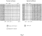
- Fig. 3 schematically illustrates an example of resource mapping according to the first embodiment.
- the left subfigure in Fig. 3 shows resource mapping of a normal subframe
- the right subfigure shows resource mapping of a special subframe.
- the data packet to be transmitted includes multiple modulated symbols which are mapped onto REs in a subframe respectively.
- there are 132 modulated symbols #0-131 in the data packet which are mapped onto 132 REs in the DL channel of the normal subframe
- the 132 modulated symbols are divided into 11 modulated-symbol sets which are sets #0-10, and each set is mapped onto one OFDM symbol in the normal subframe, i.e. one column in the left subfigure of Fig. 3 .
- set #0 including modulated symbols #0-#11 is mapped onto the first (leftmost) OFDM symbol of the repeated DL channel of the normal subframe
- set #1 including modulated symbols #12-23 is mapped onto the second OFDM symbol of the repeated DL channel of the normal subframe, and so on.
- one complete repetition of the data packet can be transmitted in one normal subframe.
- the available resources for DL transmission in DwPTS may be less than that in the normal because some resources may be used for GP and UpPTS; therefore, one special subframe may not be able to transmit one complete repetition of the data packet. In this case, only part of the modulated symbols of the data packet are transmitted in one special subframe.
- the above resource mapping rule according to the first embodiment can also be applied to the special subframe, that is, in each subframe, each OFDM symbol is mapped by one of the modulated-symbol sets. For example, as shown in the right subfigure of Fig.
- set #0 including modulated symbols #0-#11 is mapped onto the first (leftmost) OFDM symbol of the repeated DL channel of the special subframe
- set #1 including modulated symbols #12-#23 is mapped onto the second OFDM symbol of the repeated DL channel of the special subframe, and so on.
- the modulated symbols in the same modulated-symbol set are mapped onto REs in one OFDM symbol in a fixed order.
- the modulated symbols in the same set are mapped onto respective subcarriers in the same order no matter the subframe is a normal subframe or a special subframe.
- the modulated symbols #0-11 are mapped onto REs of the OFDM subframe from the top to the bottom.
- the same or fixed mapping order is used for both the normal subframe and the special subframe.
- the mapping order is the same for all the subframes for repeatedly transmitting the data packet (i.e., every subframe).
- the same modulated symbol will be mapped onto the same subcarrier in different repetitions or subframes. Therefore, the symbol level combining at the receiver side becomes possible. Using the symbol level combining, the receiver needs not to do channel estimation, channel equalization and demodulation of each repetition. This will reduce the complexity and power consumption of the UEs, in particular, MTC UEs, which is the main requirement of MTC UEs or many other UEs.
- Fig. 3 takes the downlink transmission as an example in which the data packet is transmitted in DwPTS when it is transmitted in the special subframe, but the first embodiment can also be applied to uplink transmission in which the data packet can be transmitted in UpPTS when it is transmitted in the special subframe.
- the available OFDM symbols for the transmission in a special subframe is smaller than that in a normal subframe, only part of the modulated symbols of the data packet are transmitted in one special subframe, and all the modulated symbols of the data packet can be transmitted cyclically in different special subframes.
- sets #0-4 are transmitted in the first special subframe
- sets #5-9 are transmitted in the second special subframe
- set #10 and sets #0-3 are transmitted in the third special subframe, and so on.
- all the modulated symbols can obtain balanced repetition gain.
- reference signals are to be considered in the resource mapping.
- the modulated-symbol set transmitted in an OFDM symbol with RSs in the normal subframe can be also transmitted in an OFDM symbol with the RSs in a special subframe (e.g., in DwPTS). It is noted that the RSs in the normal subframe and the RSs in the special subframe here refer to the same kind of RS.
- the modulated-symbol set transmitted in an OFDM symbol with CRS in the normal subframe is also transmitted in an OFDM symbol with CRS in DwPTS
- the modulated-symbol set transmitted in an OFDM symbol with DMRS in the normal subframe is also transmitted in an OFDM symbol with DMRS in DwPTS.
- the modulated-symbol sets transmitted in OFDM symbols with the RSs in the normal downlink subframe are transmitted cyclically in OFDM symbols with the RSs in DwPTS of multiple special subframes.
- the modulated-symbol sets transmitted in OFDM symbols without any RS in a normal downlink subframe are transmitted cyclically in OFDM symbols without any RS in DwPTS of multiple special subframes.
- Fig. 4 schematically illustrates exemplary resource mapping considering CRS according to an example of the first embodiment.
- the modulated-symbol set transmitted in an OFDM symbol with CRS in the normal subframe is transmitted in an OFDM symbol with CRS in DwPTS.
- the four subfigures of Fig. 4 are the normal DL subframe, the special subframe #1, the special subframe #2, and the special subframe #3 respectively, in which the dotted REs represent the CRS positions (REs).
- the modulated-symbol set consisting of the modulated symbols #0-7, the modulated-symbol set consisting of the modulated symbols #32-39, and the modulated-symbol set consisting of the modulated symbols #76-83 are mapped onto OFDM symbols with CRS (the OFDM symbols #4, #7 and #11) in the normal subframe respectively, and those modulated-symbol sets are also mapped onto OFDM symbols with CRS (the OFDM symbols #4 and #7) in the special subframes.
- the modulated-symbol sets transmitted in OFDM symbols with CRS in the normal downlink subframe are transmitted cyclically in OFDM symbols with CRS in DwPTS of multiple special subframes.
- the special subframe #2 transmits the set consisting of the modulated symbols #0-7 again after finishing the transmission of the set consisting of the modulated symbols #76-83.
- the modulated-symbol sets transmitted in OFDM symbols without CRS in the normal downlink subframe can be transmitted cyclically in OFDM symbols without CRS in DwPTS. According to the example shown in Fig. 4 , the performance imbalance among the modulated symbols transmitted in OFDM symbols with CRS is alleviated without changing the mapped subcarrier.
- Fig. 5 schematically illustrates exemplary resource mapping considering DMRS according to an example of the first embodiment.
- the modulated-symbol set transmitted in an OFDM symbol with DMRS in the normal subframe is transmitted in an OFDM symbol with DMRS in DwPTS.
- the five subfigures of Fig. 5 are the normal DL subframe, the special subframe with configuration 1, 2, 6 or 7 as defined in Table 1, the special subframe with configuration 3, 4 or 8, the special subframe #1 with configuration 9, and the special subframe #2 with configuration 9 respectively, in which the dotted REs represent the CRS positions and the gray REs represent the DMRS positions.
- the modulated-symbol set consisting of the modulated symbols #0-8, the modulated-symbol set consisting of the modulated symbols #9-17, the modulated-symbol set consisting of the modulated symbols #70-78, and the modulated-symbol set consisting of the modulated symbols #79-87 are mapped onto OFDM symbols with DMRS (the OFDM symbols #5, #6, #12 and #13) in the normal subframe respectively, and those modulated-symbol sets are also mapped onto OFDM symbols with DMRS in the special subframes.
- the modulated-symbol sets transmitted in OFDM symbols with DMRS in the normal downlink subframe can be transmitted cyclically in OFDM symbols with DMRS in DwPTS of multiple special subframes with configuration 9.
- the special subframes #1 and #2 with configuration 9 both transmit two different modulated-symbol sets respectively.
- the modulated-symbol sets transmitted in OFDM symbols without DMRS in the normal downlink subframe can be transmitted cyclically in OFDM symbols without DMRS in DwPTS. According to the example shown in Fig.
- the same modulated symbol is mapped onto the same subcarrier even if the DMRS positions are different in the normal DL and in the special subframe, which makes the symbol level combining possible.
- the performance imbalance among the modulated symbols transmitted in OFDM symbols with CRS is also alleviated.
- Fig. 6 schematically illustrates exemplary resource mapping considering both CRS and DMRS according to an example of the first embodiment.
- the modulated-symbol set transmitted in an OFDM symbol with CRS in the normal subframe is transmitted in an OFDM symbol with CRS in DwPTS
- the modulated-symbol set transmitted in an OFDM symbol with DMRS in the normal subframe is transmitted in an OFDM symbol with DMRS in DwPTS.
- the modulated-symbol sets transmitted in OFDM symbols without any RS in the normal subframe some of them are transmitted in OFDM symbols without any RS in DwPTS, and some of them are transmitted in OFDM symbols with RSs (e.g. DMRS) in DwPTS.
- RSs e.g. DMRS
- At least one of the modulated-symbol sets transmitted in OFDM symbols without any RS in a normal downlink subframe is transmitted in OFDM symbols with RSs in DwPTS.
- the modulated symbols supposed to be transmitted in RS positions in DwPTS are punctured in the RS positions, that is, they are not transmitted in the RS positions.
- the mapping manners for the modulated-symbol sets transmitted in OFDM symbols without any RS in the normal subframe illustrated in the examples of Fig. 4 , Fig. 5 and Fig. 6 can be exchanged with each other.
- Fig. 6 Four subfigures are shown in Fig. 6 , which are the normal DL subframe, the special subframe #1 with configuration 9, the special subframe #2 with configuration 9 and the special subframe #3 with configuration 9 respectively, in which the dotted REs represent the CRS positions and the gray REs represent the DMRS positions.
- Fig. 6 shows the normal DL subframe, the special subframe #1 with configuration 9, the special subframe #2 with configuration 9 and the special subframe #3 with configuration 9 respectively, in which the dotted REs represent the CRS positions and the gray REs represent the DMRS positions.
- the modulated-symbol set consisting of the modulated symbols #12-19, the modulated-symbol set consisting of the modulated symbols #38-45, and the modulated-symbol set consisting of the modulated symbols #82-89 are mapped onto OFDM symbols with CRS (the OFDM symbols #4, #7 and #11) in the normal subframe respectively, and those modulated-symbol sets are also mapped onto OFDM symbols with CRS in the special subframes #1, #2 and #3 respectively.
- the modulated-symbol set consisting of the modulated symbols #20-28, the modulated-symbol set consisting of the modulated symbols #29-37, the modulated-symbol set consisting of the modulated symbols #90-98, and the modulated-symbol set consisting of the modulated symbols #99-107 are mapped onto OFDM symbols with DMRS (the OFDM symbols #5, #6, #12 and #13) in the normal subframe respectively, and those modulated-symbol sets are mapped onto OFDM symbols with DMRS in the special subframes #1 and #3 respectively.
- the remaining modulated-symbol sets are mapped onto OFDM symbols without any RS in the normal subfame.
- the modulated-symbol set consisting of the modulated symbols #46-57 and the modulated-symbol set consisting of the modulated symbols #58-69 are mapped onto the OFDM symbols with DMRS in the special subframe #2. Since the DMRS positions (REs) in the special subframe #2 should be used to transmit DMRS, the modulated symbols (#46, #51, #56, #58, #63 and #68 in this example) supposed to be mapped onto these RS positions are punctured in these DMRS positions, i.e., are not transmitted in these positions, as shown by "x" in the special subframe #2 of Fig. 6 . For other modulated-symbols, they can be mapped onto OFDM symbols without any RS in the special subframes.
- the modulated symbols (#46, #51, #56, #58, #63 and #68 in this example) are punctured in these DMRS positions, i.e., are not transmitted in these positions, as shown by "x" in
- Fig. 7 schematically illustrates exemplary cyclic resource mapping according to an example of the first embodiment.
- the modulated-symbol sets transmitted in a normal DL subframe are transmitted cyclically in DwPTS of multiple special subframes.
- the granularity is OFDM symbols in time domain.
- the modulated symbol sets transmitted in OFDM symbols ⁇ #3, #4, #5, #6 ⁇ , ⁇ #7, #8, #9, #10 ⁇ , ⁇ #11, #12, #13, #0 ⁇ ,... in the normal DL subframe are transmitted in special subframes#1, #2, #3,...cyclically.
- the RS REs can be handled in such a manner that the modulated symbols supposed to be transmitted in RS positions (REs) in DwPTS are punctured in the RS positions, and the REs in DwPTS corresponding to the RS REs in the normal subframe are left blank.
- Fig. 8 schematically illustrates an example of handling RS REs according to an example of the present disclosure.
- the modulated-symbol sets mapped onto OFDM symbols ⁇ #8, #9, #10, #11 ⁇ in the normal subframe are mapped onto OFDM symbols ⁇ #2, #3, #4, #5 ⁇ in the special subframe.
- the modulated symbols #26, #29, #32 and #35 are punctured in the special subframe since the REs onto which those modulated symbols are supposed to be mapped in the special subframe are CRS REs, as shown by "x" in the special subframe.
- the REs represented by "B” in the OFDM symbol #5 of the special subframe are corresponding to the CRS REs in the OFDM symbol #11 of the normal subframe according to the above mapping manner; therefore, those REs represented by "B” in the OFDM symbol #5 of the special subframe are left blank.
- the transmitting symbols are almost with complete balanced performance.
- the manner of handling RS REs illustrated in Fig. 8 can also be applied to other examples or embodiments of the present disclosure if appropriate.
- a wireless communication device for performing the above methods.
- Fig. 9 is a block diagram illustrating a wireless communication device 900 according to the first embodiment of the present disclosure.
- the wireless communication device 900 can comprise a transmitting unit 901 which is configured to transmit a data packet repeatedly in multiple subframes including at least one normal subframe and at least one special subframe to another wireless communication device (second wireless communications device), wherein the available resources in the special subframe are different from that in the normal subframe, the data packet includes multiple modulated symbols which are divided into multiple modulated-symbol sets, in each subframe, each Orthogonal Frequency Division Multiplexing (OFDM) symbol is mapped by one of the modulated-symbol sets, and in every subframe, the modulated symbols in the same modulated-symbol set are mapped onto Resource Elements (REs) in one OFDM symbol in a fixed order.
- OFDM Orthogonal Frequency Division Multiplexing
- the wireless communication device 900 may optionally include a CPU (Central Processing Unit) 910 for executing related programs to process various data and control operations of respective units in the wireless communication device 900, a ROM (Read Only Memory) 913 for storing various programs required for performing various process and control by the CPU 910, a RAM (Random Access Memory) 915 for storing intermediate data temporarily produced in the procedure of process and control by the CPU 910, and/or a storage unit 917 for storing various programs, data and so on.
- the above transmitting unit 901, CPU 910, ROM 913, RAM 915 and/or storage unit 917 etc. may be interconnected via data and/or command bus 920 and transfer signals between one another.
- Respective units as described above do not limit the scope of the present disclosure.
- the functions of the above transmitting unit 901 may be implemented by hardware, and the above CPU 910, ROM 913, RAM 915 and/or storage unit 917 may not be necessary.
- the functions of the above transmitting unit 901 may also be implemented by functional software in combination with the above CPU 910, ROM 913, RAM 915 and/or storage unit 917 etc.
- the first embodiment provides a wireless communication method 1000 performed by a wireless communication device (second communication device) as shown in Fig. 10 .
- the wireless communication method 1000 comprising a step 1001 of receiving a data packet which is repeatedly transmitted in multiple subframes including at least one normal subframe and at least one special subframe from another wireless communication device (first communication device), wherein the available resources in the special subframe are different from that in the normal subframe, the data packet includes multiple modulated symbols which are divided into multiple modulated-symbol sets, in each subframe, each Orthogonal Frequency Division Multiplexing (OFDM) symbol is mapped by one of the modulated-symbol sets, and in every subframe, the modulated symbols in the same modulated-symbol set are mapped onto Resource Elements (REs) in one OFDM symbol in a fixed order.
- OFDM Orthogonal Frequency Division Multiplexing
- a wireless communication device for performing the above method at the receiving side.
- Fig. 11 is a block diagram illustrating a wireless communication device 1100 at the receiving side according to the first embodiment of the present disclosure.
- the wireless communication device 1100 can comprise a receiving unit 1101 configured to receive a data packet which is repeatedly transmitted in multiple subframes including at least one normal subframe and at least one special subframe from another wireless communication device (first wireless communications device), wherein the available resources in the special subframe are different from that in the normal subframe, the data packet includes multiple modulated symbols which are divided into multiple modulated-symbol sets, in each subframe, each Orthogonal Frequency Division Multiplexing (OFDM) symbol is mapped by one of the modulated-symbol sets, and in every subframe, the modulated symbols in the same modulated-symbol set are mapped onto Resource Elements (REs) in one OFDM symbol in a fixed order.
- OFDM Orthogonal Frequency Division Multiplexing
- the wireless communication device 1100 may optionally include a CPU (Central Processing Unit) 1110 for executing related programs to process various data and control operations of respective units in the wireless communication device 1100, a ROM (Read Only Memory) 1113 for storing various programs required for performing various process and control by the CPU 1110, a RAM (Random Access Memory) 1115 for storing intermediate data temporarily produced in the procedure of process and control by the CPU 1110, and/or a storage unit 1117 for storing various programs, data and so on.
- the above receiving unit 1101, CPU 1110, ROM 1113, RAM 1115 and/or storage unit 1117 etc. may be interconnected via data and/or command bus 1120 and transfer signals between one another,
- Respective units as described above do not limit the scope of the present disclosure.
- the functions of the above receiving unit 1101 may be implemented by hardware, and the above CPU 1110, ROM 1113, RAM 1115 and/or storage unit 1117 may not be necessary.
- the functions of the above receiving unit 1101 may also be implemented by functional software in combination with the above CPU 1110, ROM 1113, RAM 1115 and/or storage unit 1117 etc.
- the second embodiment of the present disclosure provides a wireless communication method performed by a wireless communication device (first communication device).
- the wireless communication method can comprises a step of transmitting a data packet repeatedly in multiple subframes including at least one normal subframe and at least one special subframe to another wireless communication device (second communication device), wherein the available resources in the special subframe are different from that in the normal subframe.
- the wireless communication method in the second embodiment can have the same flowchart as shown in Fig. 2 for the first embodiment, and the details described for the first embodiment may also be applied to the second embodiment unless the context indicates otherwise.
- Fig. 13 illustrates an example of the resource mapping with cyclic shift according to the second embodiment, in which 6 repetitions in one subframe is taken as an example.
- the left subfigure of Fig. 13 shows normal mapping without shift in a normal subframe, and the right subfigure shows modified mapping with cyclic shift in the normal subframe.
- each PRB pair comprises three subcarriers for transmitting one repetition, and in each PRB pair, modulated symbols of the data packet are mapped onto REs for example in an order of mapping first in the frequency domain and then in the time domain.
- the difference between the normal mapping and the modified mapping is as follows. In the normal mapping, each repetition is mapped onto one PRB pair in exactly the same manner; however, in the modified mapping, among the repetitions in one subframe, cyclic shift is applied to the mapping. As shown in the modified mapping of Fig. 13 , cyclic shift of 6 modulated symbols is applied between adjacent repetitions.
- the second embodiment is not limited to the specific mapping manner shown in Fig. 13 .
- the cyclic shift is not limited to 6 modulated symbols, but can be any appropriate number of modulated symbols, and the number of subcarriers in each PRB pair is not limited to 3.
- the modulated symbols of the first three OFDM symbols of the repeated DL channel of the normal symbol can always be truncated to be mapped onto DwPTS of special subframes. It can be seen that almost every modulated symbol can be included in the truncated part due to the cyclic shift; therefore balanced performance can be obtained among the modulated symbols of the data packet.
- the normal subframes can also adopt other mapping manners such as the normal mapping shown in Fig. 13 , but the special subframes employ the mapping with cyclic shift.
- some implementations of the first embodiment can be combined with the second embodiment unless the context indicates otherwise.
- a wireless communication device comprising a transmitting unit configured to transmit a data packet repeatedly in multiple subframes including at least one normal subframe and at least one special subframe to another wireless communication device, wherein the available resources in the special subframe are different from that in the normal subframe, multiple repetitions of the data packet are transmitted in each subframe, and in each special subframe, different repetitions are mapped onto Resource Elements (REs) with cyclic shift.
- the first wireless communication device in the second embodiment can have the same structure as that in the first embodiment shown in Fig. 9 .
- the second embodiment also provides a wireless communication method performed by a wireless communication device (second communication device).
- the wireless communication method here can have the same flowchart as shown in Fig. 10 and comprise a step of receiving a data packet which is repeatedly transmitted in multiple subframes including at least one normal subframe and at least one special subframe from another wireless communication device (first communication device), wherein the available resources in the special subframe are different from that in the normal subframe, multiple repetitions of the data packet are transmitted in each subframe, and in each special subframe, different repetitions are mapped onto Resource Elements (REs) with cyclic shift.
- REs Resource Elements
- a wireless communication device for the receiving side comprising a receiving unit configured to receive a data packet which is repeatedly transmitted in multiple subframes including at least one normal subframe and at least one special subframe from another wireless communication device (first wireless communication device), wherein the available resources in the special subframe are different from that in the normal subframe, multiple repetitions of the data packet are transmitted in each subframe, and in each special subframe, different repetitions are mapped onto Resource Elements (REs) with cyclic shift.
- the second wireless communication device in the second embodiment can have the same structure as that in the first embodiment shown in Fig. 11 .
- the present invention can be realized by software, hardware, or software in cooperation with hardware.
- Each functional block used in the description of each embodiment described above can be realized by an LSI as an integrated circuit. They may be individually formed as chips, or one chip may be formed so as to include a part or all of the functional blocks.
- the LSI here may be referred to as an IC, a system LSI, a super LSI, or an ultra LSI depending on a difference in the degree of integration.
- the technique of implementing an integrated circuit is not limited to the LSI and may be realized by using a dedicated circuit or a general-purpose processor.
- a FPGA Field Programmable Gate Array
- a reconfigurable processor in which the connections and the settings of circuits cells disposed inside the LSI can be reconfigured may be used.
- the calculation of each functional block can be performed by using calculating means, for example, including a DSP or a CPU, and the processing step of each function may be recorded on a recording medium as a program for execution.
- the functional block may be integrated by using such technologies.
Abstract
Description
- The present disclosure relates to the field of wireless communication, and in particular, to wireless communication methods and wireless communication devices such as an eNode B (eNB) or a user equipment (UE),
- Machine-Type Communication (MTC) is an important revenue stream for operators and has a huge potential from the operator perspective. Based on the market and operators' requirements, one of the important requirements of MTC is improving the coverage of MTC UEs. To enhance the MTC coverage, almost all of the physical channels need to be enhanced. Repetition in time domain is the main method to improve the coverage of the channels. At the receiver side, the receiver combines all the repetitions of the channel and decodes the information.
- In Time Division Duplexing (TDD), not all the subframes in one frame are used for downlink (DL) or uplink (UL) transmission. According to the frame structure in LTE specification, there are DL subframes, UL subframes and special subframes in one frame. In a special subframe, it includes DwPTS, GP and UpPTS, as shown in
Fig. 1 which schematically illustrates the structure of a special subframe in TDD. Downlink channel can be transmitted in DwPTS, and uplink channel can be transmitted in UpPTS. - For different special subframe configurations, the lengths of DwPTS and UpPTS are different. Take DwPTS for example, the lengths of DwPTS according to the special subframe configurations are listed in the table below (Table 1).
Table 1 Special subframe configuration Normal cyclic prefix in downlink DwPTS (number of OFDM symbols) 0 3 1 9 2 10 3 11 4 12 5 3 6 9 7 10 6 11 9 6 - For MTC in coverage enhancement mode, the repetitions of one channel are transmitted in multiple subframes. To fully use the downlink or uplink resource and reduce the latency, it is better to also use DwPTS or UpPTS to transmit downlink or uplink channel repetitions. As the available resources in the special subframe are different from that in the normal subframe, how to map repetition in DwPTS or UpPTS in a special subframe becomes a problem.
- In a first aspect of the present disclosure, there is provided a wireless communication method performed by a wireless communication device, comprising a step of transmitting a data packet repeatedly in multiple subframes including at least one normal subframe and at least one special subframe to another wireless communication device, wherein the available resources in the special subframe are different from that in the normal subframe, the data packet includes multiple modulated symbols which are divided into multiple modulated-symbol sets, in each subframe, each Orthogonal Frequency Division Multiplexing (OFDM) symbol is mapped by one of the modulated-symbol sets, and in every subframe, the modulated symbols in the same modulated-symbol set are mapped onto Resource Elements (REs) in one OFDM symbol in a fixed order.
- In a second aspect of the present disclosure, there is provided a wireless communication method performed by a wireless communication device, comprising a step of transmitting a data packet repeatedly in multiple subframes including at least one normal subframe and at least one special subframe to another wireless communication device, wherein the available resources in the special subframe are different from that in the normal subframe, multiple repetitions of the data packet are transmitted in each subframe, and in each special subframe, different repetitions are mapped onto Resource Elements (REs) with cyclic shift.
- In a third aspect of the present disclosure, there is provided a wireless communication method performed by a wireless communication device, comprising a step of receiving a data packet which is repeatedly transmitted in multiple subframes including at least one normal subframe and at least one special subframe from another wireless communication device, wherein the available resources in the special subframe are different from that in the normal subframe, the data packet includes multiple modulated symbols which are divided into multiple modulated-symbol sets, in each subframe, each Orthogonal Frequency Division Multiplexing (OFDM) symbol is mapped by one of the modulated-symbol sets, and in every subframe, the modulated symbols in the same modulated-symbol set are mapped onto Resource Elements (REs) in one OFDM symbol in a fixed order.
- In a fourth aspect of the present disclosure, there is provided a wireless communication method performed by a wireless communication device, comprising a step of receiving a data packet which is repeatedly transmitted in multiple subframes including at least one normal subframe and at least one special subframe from another wireless communication device, wherein the available resources in the special subframe are different from that in the normal subframe, multiple repetitions of the data packet are transmitted in each subframe, and in each special subframe, different repetitions are mapped onto Resource Elements (REs) with cyclic shift.
- In a fifth aspect of the present disclosure, there is provided a wireless communication device comprising: a transmitting unit configured to transmit a data packet repeatedly in multiple subframes including at least one normal subframe and at least one special subframe to another wireless communication device, wherein the available resources in the special subframe are different from that in the normal subframe, the data packet includes multiple modulated symbols which are divided into multiple modulated-symbol sets, in each subframe, each Orthogonal Frequency Division Multiplexing (OFDM) symbol is mapped by one of the modulated-symbol sets, and in every subframe, the modulated symbols in the same modulated-symbol set are mapped onto Resource Elements (REs) in one OFDM symbol in a fixed order.
- In a sixth aspect of the present disclosure, there is provided a wireless communication device comprising a transmitting unit configured to transmit a data packet repeatedly in multiple subframes including at least one normal subframe and at least one special subframe to another wireless communication device, wherein the available resources in the special subframe are different from that in the normal subframe, multiple repetitions of the data packet are transmitted in each subframe, and in each special subframe, different repetitions are mapped onto Resource Elements (REs) with cyclic shift.
- In a seventh aspect of the present disclosure, there is provided a wireless communication device comprising a receiving unit configured to receive a data packet which is repeatedly transmitted in multiple subframes including at least one normal subframe and at least one special subframe from another wireless communication device, wherein the available resources in the special subframe are different from that in the normal subframe, the data packet includes multiple modulated symbols which are divided into multiple modulated-symbol sets, in each subframe, each Orthogonal Frequency Division Multiplexing (OFDM) symbol is mapped by one of the modulated-symbol sets, and in every subframe, the modulated symbols in the same modulated-symbol set are mapped onto Resource Elements (REs) in one OFDM symbol in a fixed order.
- In a eighth aspect of the present disclosure, there is provided a wireless communication device comprising a receiving unit configured to receive a data packet which is repeatedly transmitted in multiple subframes including at least one normal subframe and at least one special subframe from another wireless communication device, wherein the available resources in the special subframe are different from that in the normal subframe, multiple repetitions of the data packet are transmitted in each subframe, and in each special subframe, different repetitions are mapped onto Resource Elements (REs) with cyclic shift.
- The foregoing is a summary and thus contains, by necessity, simplifications, generalization, and omissions of details. Other aspects, features, and advantages of the devices and/or processes and/or other subject matters described herein will become apparent in the teachings set forth herein. The summary is provided to introduce a selection of concepts in a simplified form that are further described below in the Detailed Description. This summary is not intended to identify key features or essential features of the claimed subject matter, nor is it intended to be used as an aid in determining the scope of the claimed subject matter.
- The foregoing and other features of the present disclosure will become more fully apparent from the following description and appended claims, taken in conjunction with the accompanying drawings. Understanding that these drawings depict only several embodiments in accordance with the disclosure and are, therefore, not to be considered limiting of its scope, the disclosure will be described with additional specificity and detail through use of the accompanying drawings, in which:
-
Fig. 1 schematically illustrates the structure of a special subframe in TDD; -
Fig. 2 schematically illustrates a flowchart of a wireless communication method at the transmitting side according to a first embodiment of the present disclosure; -
Fig. 3 schematically illustrates an example of resource mapping according to the first embodiment; -
Fig. 4 schematically illustrates exemplary resource mapping considering CRS according to an example of the first embodiment; -
Fig. 5 schematically illustrates exemplary resource mapping considering DMRS according to an example of the first embodiment; -
Fig. 6 schematically illustrates exemplary resource mapping considering both CRS and DMRS according to an example of the first embodiment; -
Fig. 7 schematically illustrates exemplary cyclic resource mapping according to an example of the first embodiment; -
Fig. 8 schematically illustrates an example of handling RS REs according to an example of the present disclosure; -
Fig. 9 schematically illustrates a block diagram of a wireless communication device at the transmitting side according to the first embodiment; -
Fig. 10 schematically illustrates a flowchart of a wireless communication method at the receiving side according to the first embodiment of the present disclosure; -
Fig. 11 schematically illustrates a block diagram of a wireless communication device at the receiving side according to the first embodiment; -
Fig. 12 schematically illustrates multiple repetitions transmitted in one subframe; and -
Fig. 13 illustrates an example of resource mapping with cyclic shift according to a second embodiment of the present disclosure. - In the following detailed description, reference is made to the accompanying drawings, which form a part thereof. In the drawings, similar symbols typically identify similar components, unless context dictates otherwise. It will be readily understood that the aspects of the present disclosure can be arranged, substituted, combined, and designed in a wide variety of different configurations, all of which are explicitly contemplated and make part of this disclosure.
- In the present disclosure, wireless communication methods performed by wireless communication devices are provided. Herein, the wireless communication methods can be applied to any type of wireless communications, for example but not limited to communications conforming to LTE specifications, preferably MTC. Similarly, the wireless communication devices can be any devices with wireless communication function such as eNBs or UEs. In addition, in the following description, TDD and downlink transmission may be taken as examples to explain the present disclosure; however, it is noted that the present disclosure is not limited to TDD and downlink transmission but can also be applied to FDD and uplink transmission.
- In the first embodiment of the present disclosure, there is provided a
wireless communication method 200 performed by a wireless communication device (first wireless communication device), as shown inFig. 2 which schematically illustrates the flowchart of thewireless communication method 200 according to the first embodiment. Thewireless communication method 200 comprises astep 201 of transmitting a data packet repeatedly in multiple subframes including at least one normal subframe and at least one special subframe to another wireless communication device (second communication device). In this communication method, the data packet is transmitted repeatedly in multiple subframes in order to enhance the physical channel. This repeated transmission is in particular suitable for MTC, but not limited to MTC. It can be applied to any wireless communication requiring channel enhancement. The first communication device and the second communication device can be an eNB, a UE or the like depending on specific application scenarios For example, if the communication method is applied to downlink communication, the first communication device can be an eNB or the like, and the second communication device can be a UE or the like. Similarly, if the communication method is applied to uplink communication, the first communication device can be an UE or the like, and the second communication device can be an eNB or the like. In the first embodiment, the repeated transmission is performed in two kinds of subframes which are the normal subframe and the specific subframe. The normal subframe and the specific subframe herein can be that defined according to the frame structure in LTE specifications; however, the normal subframe and the specific subframe herein can also be defined otherwise so far as the available resources in the special subframe are different from that in the normal subframe. - In the first embodiment, the data packet includes multiple modulated symbols, and these modulated symbols are divided into multiple modulated-symbol sets. In each subframe, each Orthogonal Frequency Division Multiplexing (OFDM) symbol is mapped by one of the modulated-symbol sets, and in every subframe, the modulated symbols in the same modulated-symbol set are mapped onto Resource Elements (REs) in one OFDM symbol in a fixed order.
-
Fig. 3 schematically illustrates an example of resource mapping according to the first embodiment. The left subfigure inFig. 3 shows resource mapping of a normal subframe, and the right subfigure shows resource mapping of a special subframe. The data packet to be transmitted includes multiple modulated symbols which are mapped onto REs in a subframe respectively. As shown in the normal subframe ofFig. 3 , there are 132 modulated symbols #0-131 in the data packet which are mapped onto 132 REs in the DL channel of the normal subframe, The 132 modulated symbols are divided into 11 modulated-symbol sets which are sets #0-10, and each set is mapped onto one OFDM symbol in the normal subframe, i.e. one column in the left subfigure ofFig. 3 . - For example, set #0 including modulated symbols #0-#11 is mapped onto the first (leftmost) OFDM symbol of the repeated DL channel of the normal subframe, set #1 including modulated symbols #12-23 is mapped onto the second OFDM symbol of the repeated DL channel of the normal subframe, and so on. In this example, one complete repetition of the data packet can be transmitted in one normal subframe.
- For a special subframe, the available resources for DL transmission in DwPTS may be less than that in the normal because some resources may be used for GP and UpPTS; therefore, one special subframe may not be able to transmit one complete repetition of the data packet. In this case, only part of the modulated symbols of the data packet are transmitted in one special subframe. However, the above resource mapping rule according to the first embodiment can also be applied to the special subframe, that is, in each subframe, each OFDM symbol is mapped by one of the modulated-symbol sets. For example, as shown in the right subfigure of
Fig. 3 , set #0 including modulated symbols #0-#11 is mapped onto the first (leftmost) OFDM symbol of the repeated DL channel of the special subframe, set #1 including modulated symbols #12-#23 is mapped onto the second OFDM symbol of the repeated DL channel of the special subframe, and so on. - In addition, according to the first embodiment, in every subframe, the modulated symbols in the same modulated-symbol set are mapped onto REs in one OFDM symbol in a fixed order. In other words, for all the subframes for repeatedly transmitting the data packet, the modulated symbols in the same set are mapped onto respective subcarriers in the same order no matter the subframe is a normal subframe or a special subframe. For example, for the
set # 0 including modulated symbols #0-11 in theFig. 3 , for both the normal subframe and the special subframe, the modulated symbols #0-11 are mapped onto REs of the OFDM subframe from the top to the bottom. In other words, the same or fixed mapping order is used for both the normal subframe and the special subframe. According to the first embodiment, the mapping order is the same for all the subframes for repeatedly transmitting the data packet (i.e., every subframe). - According to the first embodiment of the present disclosure, since one modulated symbol set is mapped onto one OFDM symbol in each subframe and the modulated symbols in the same modulated-symbol set are mapped onto REs in one OFDM symbol in a fixed order in every subframe, the same modulated symbol will be mapped onto the same subcarrier in different repetitions or subframes. Therefore, the symbol level combining at the receiver side becomes possible. Using the symbol level combining, the receiver needs not to do channel estimation, channel equalization and demodulation of each repetition. This will reduce the complexity and power consumption of the UEs, in particular, MTC UEs, which is the main requirement of MTC UEs or many other UEs.
- It is noted that,
Fig. 3 takes the downlink transmission as an example in which the data packet is transmitted in DwPTS when it is transmitted in the special subframe, but the first embodiment can also be applied to uplink transmission in which the data packet can be transmitted in UpPTS when it is transmitted in the special subframe. In addition, if the available OFDM symbols for the transmission in a special subframe is smaller than that in a normal subframe, only part of the modulated symbols of the data packet are transmitted in one special subframe, and all the modulated symbols of the data packet can be transmitted cyclically in different special subframes. For example, sets #0-4 are transmitted in the first special subframe, sets #5-9 are transmitted in the second special subframe, set #10 and sets #0-3 are transmitted in the third special subframe, and so on. In this manner, all the modulated symbols can obtain balanced repetition gain. However, alternatively, it is possible to always truncate the same part of the modulated symbols to be transmitted in different special subframes. - Further, as an improvement to the first embodiment, reference signals (RSs) are to be considered in the resource mapping. In a preferable embodiment, the modulated-symbol set transmitted in an OFDM symbol with RSs in the normal subframe can be also transmitted in an OFDM symbol with the RSs in a special subframe (e.g., in DwPTS). It is noted that the RSs in the normal subframe and the RSs in the special subframe here refer to the same kind of RS. For example, the modulated-symbol set transmitted in an OFDM symbol with CRS in the normal subframe is also transmitted in an OFDM symbol with CRS in DwPTS, and similarly the modulated-symbol set transmitted in an OFDM symbol with DMRS in the normal subframe is also transmitted in an OFDM symbol with DMRS in DwPTS. In addition, preferably, if the number of the OFDM symbols with the RSs in DwPTS is less than that in the normal downlink subframe, the modulated-symbol sets transmitted in OFDM symbols with the RSs in the normal downlink subframe are transmitted cyclically in OFDM symbols with the RSs in DwPTS of multiple special subframes. And preferably, the modulated-symbol sets transmitted in OFDM symbols without any RS in a normal downlink subframe are transmitted cyclically in OFDM symbols without any RS in DwPTS of multiple special subframes.
-
Fig. 4 schematically illustrates exemplary resource mapping considering CRS according to an example of the first embodiment. In this example, the modulated-symbol set transmitted in an OFDM symbol with CRS in the normal subframe is transmitted in an OFDM symbol with CRS in DwPTS. The four subfigures ofFig. 4 are the normal DL subframe, thespecial subframe # 1, thespecial subframe # 2, and thespecial subframe # 3 respectively, in which the dotted REs represent the CRS positions (REs). It can be seen that the modulated-symbol set consisting of the modulated symbols #0-7, the modulated-symbol set consisting of the modulated symbols #32-39, and the modulated-symbol set consisting of the modulated symbols #76-83 are mapped onto OFDM symbols with CRS (theOFDM symbols # 4, #7 and #11) in the normal subframe respectively, and those modulated-symbol sets are also mapped onto OFDM symbols with CRS (theOFDM symbols # 4 and #7) in the special subframes. In addition, in this example, since the number of the OFDM symbols with CRS in DwPTS of the special subframes is less than that in the normal DL subframe, the modulated-symbol sets transmitted in OFDM symbols with CRS in the normal downlink subframe are transmitted cyclically in OFDM symbols with CRS in DwPTS of multiple special subframes. As shown inFig. 4 , thespecial subframe # 2 transmits the set consisting of the modulated symbols #0-7 again after finishing the transmission of the set consisting of the modulated symbols #76-83. In addition, optionally, the modulated-symbol sets transmitted in OFDM symbols without CRS in the normal downlink subframe can be transmitted cyclically in OFDM symbols without CRS in DwPTS. According to the example shown inFig. 4 , the performance imbalance among the modulated symbols transmitted in OFDM symbols with CRS is alleviated without changing the mapped subcarrier. -
Fig. 5 schematically illustrates exemplary resource mapping considering DMRS according to an example of the first embodiment. In this example, the modulated-symbol set transmitted in an OFDM symbol with DMRS in the normal subframe is transmitted in an OFDM symbol with DMRS in DwPTS. The five subfigures ofFig. 5 are the normal DL subframe, the special subframe withconfiguration configuration special subframe # 1 withconfiguration 9, and thespecial subframe # 2 withconfiguration 9 respectively, in which the dotted REs represent the CRS positions and the gray REs represent the DMRS positions. It can be seen that the modulated-symbol set consisting of the modulated symbols #0-8, the modulated-symbol set consisting of the modulated symbols #9-17, the modulated-symbol set consisting of the modulated symbols #70-78, and the modulated-symbol set consisting of the modulated symbols #79-87 are mapped onto OFDM symbols with DMRS (theOFDM symbols # 5, #6, #12 and #13) in the normal subframe respectively, and those modulated-symbol sets are also mapped onto OFDM symbols with DMRS in the special subframes. In addition, in this example, since the number of the OFDM symbols with DMRS in DwPTS of the special subframes withconfiguration 9 is less than that in the normal downlink subframe, the modulated-symbol sets transmitted in OFDM symbols with DMRS in the normal downlink subframe can be transmitted cyclically in OFDM symbols with DMRS in DwPTS of multiple special subframes withconfiguration 9. As shown inFig. 5 , thespecial subframes # 1 and #2 withconfiguration 9 both transmit two different modulated-symbol sets respectively. In addition, optionally, the modulated-symbol sets transmitted in OFDM symbols without DMRS in the normal downlink subframe can be transmitted cyclically in OFDM symbols without DMRS in DwPTS. According to the example shown inFig. 5 , the same modulated symbol is mapped onto the same subcarrier even if the DMRS positions are different in the normal DL and in the special subframe, which makes the symbol level combining possible. In addition, the performance imbalance among the modulated symbols transmitted in OFDM symbols with CRS is also alleviated. -
Fig. 6 schematically illustrates exemplary resource mapping considering both CRS and DMRS according to an example of the first embodiment. In this example, the modulated-symbol set transmitted in an OFDM symbol with CRS in the normal subframe is transmitted in an OFDM symbol with CRS in DwPTS, and the modulated-symbol set transmitted in an OFDM symbol with DMRS in the normal subframe is transmitted in an OFDM symbol with DMRS in DwPTS. As for the modulated-symbol sets transmitted in OFDM symbols without any RS in the normal subframe, some of them are transmitted in OFDM symbols without any RS in DwPTS, and some of them are transmitted in OFDM symbols with RSs (e.g. DMRS) in DwPTS. In other words, at least one of the modulated-symbol sets transmitted in OFDM symbols without any RS in a normal downlink subframe is transmitted in OFDM symbols with RSs in DwPTS. The modulated symbols supposed to be transmitted in RS positions in DwPTS are punctured in the RS positions, that is, they are not transmitted in the RS positions. In this manner, it is possible to make the repeated transmission of modulated symbols mapped onto OFDM symbols with RS and without RS more balanced. It is noted that the mapping manners for the modulated-symbol sets transmitted in OFDM symbols without any RS in the normal subframe illustrated in the examples ofFig. 4 ,Fig. 5 andFig. 6 can be exchanged with each other. - Four subfigures are shown in
Fig. 6 , which are the normal DL subframe, thespecial subframe # 1 withconfiguration 9, thespecial subframe # 2 withconfiguration 9 and thespecial subframe # 3 withconfiguration 9 respectively, in which the dotted REs represent the CRS positions and the gray REs represent the DMRS positions. As can be seen inFig. 6 , the modulated-symbol set consisting of the modulated symbols #12-19, the modulated-symbol set consisting of the modulated symbols #38-45, and the modulated-symbol set consisting of the modulated symbols #82-89 are mapped onto OFDM symbols with CRS (theOFDM symbols # 4, #7 and #11) in the normal subframe respectively, and those modulated-symbol sets are also mapped onto OFDM symbols with CRS in thespecial subframes # 1, #2 and #3 respectively. The modulated-symbol set consisting of the modulated symbols #20-28, the modulated-symbol set consisting of the modulated symbols #29-37, the modulated-symbol set consisting of the modulated symbols #90-98, and the modulated-symbol set consisting of the modulated symbols #99-107 are mapped onto OFDM symbols with DMRS (theOFDM symbols # 5, #6, #12 and #13) in the normal subframe respectively, and those modulated-symbol sets are mapped onto OFDM symbols with DMRS in thespecial subframes # 1 and #3 respectively. The remaining modulated-symbol sets are mapped onto OFDM symbols without any RS in the normal subfame. Among these remaining modulated-symbol sets, the modulated-symbol set consisting of the modulated symbols #46-57 and the modulated-symbol set consisting of the modulated symbols #58-69 are mapped onto the OFDM symbols with DMRS in thespecial subframe # 2. Since the DMRS positions (REs) in thespecial subframe # 2 should be used to transmit DMRS, the modulated symbols (#46, #51, #56, #58, #63 and #68 in this example) supposed to be mapped onto these RS positions are punctured in these DMRS positions, i.e., are not transmitted in these positions, as shown by "x" in thespecial subframe # 2 ofFig. 6 . For other modulated-symbols, they can be mapped onto OFDM symbols without any RS in the special subframes. -
Fig. 7 schematically illustrates exemplary cyclic resource mapping according to an example of the first embodiment. In this example, the modulated-symbol sets transmitted in a normal DL subframe are transmitted cyclically in DwPTS of multiple special subframes. The granularity is OFDM symbols in time domain. As shown inFig. 7 , the modulated symbol sets transmitted in OFDM symbols {#3, #4, #5, #6}, {#7, #8, #9, #10}, {#11, #12, #13, #0},... in the normal DL subframe are transmitted inspecial subframes# 1, #2, #3,...cyclically. - In the above example, the RS REs can be handled in such a manner that the modulated symbols supposed to be transmitted in RS positions (REs) in DwPTS are punctured in the RS positions, and the REs in DwPTS corresponding to the RS REs in the normal subframe are left blank.
Fig. 8 schematically illustrates an example of handling RS REs according to an example of the present disclosure. InFig. 8 , the modulated-symbol sets mapped onto OFDM symbols {#8, #9, #10, #11} in the normal subframe are mapped onto OFDM symbols {#2, #3, #4, #5} in the special subframe. The modulatedsymbols # 26, #29, #32 and #35 are punctured in the special subframe since the REs onto which those modulated symbols are supposed to be mapped in the special subframe are CRS REs, as shown by "x" in the special subframe. In addition, the REs represented by "B" in theOFDM symbol # 5 of the special subframe are corresponding to the CRS REs in theOFDM symbol # 11 of the normal subframe according to the above mapping manner; therefore, those REs represented by "B" in theOFDM symbol # 5 of the special subframe are left blank. - According to the example shown in
Fig.7 andFig. 8 , the transmitting symbols are almost with complete balanced performance. In addition, there is no need to consider the RS positions, and thus it is easy to implement. It is noted that the manner of handling RS REs illustrated inFig. 8 can also be applied to other examples or embodiments of the present disclosure if appropriate. - In the first embodiment, there is also provided a wireless communication device (first wireless communication) for performing the above methods.
Fig. 9 is a block diagram illustrating awireless communication device 900 according to the first embodiment of the present disclosure. Thewireless communication device 900 can comprise a transmittingunit 901 which is configured to transmit a data packet repeatedly in multiple subframes including at least one normal subframe and at least one special subframe to another wireless communication device (second wireless communications device), wherein the available resources in the special subframe are different from that in the normal subframe, the data packet includes multiple modulated symbols which are divided into multiple modulated-symbol sets, in each subframe, each Orthogonal Frequency Division Multiplexing (OFDM) symbol is mapped by one of the modulated-symbol sets, and in every subframe, the modulated symbols in the same modulated-symbol set are mapped onto Resource Elements (REs) in one OFDM symbol in a fixed order. It is noted that the above explanations for the methods are also applied to the device here, which will not be repeated again. - The
wireless communication device 900 according to the present disclosure may optionally include a CPU (Central Processing Unit) 910 for executing related programs to process various data and control operations of respective units in thewireless communication device 900, a ROM (Read Only Memory) 913 for storing various programs required for performing various process and control by theCPU 910, a RAM (Random Access Memory) 915 for storing intermediate data temporarily produced in the procedure of process and control by theCPU 910, and/or astorage unit 917 for storing various programs, data and so on. Theabove transmitting unit 901,CPU 910,ROM 913,RAM 915 and/orstorage unit 917 etc. may be interconnected via data and/orcommand bus 920 and transfer signals between one another. - Respective units as described above do not limit the scope of the present disclosure. According to one implementation of the disclosure, the functions of the
above transmitting unit 901 may be implemented by hardware, and theabove CPU 910,ROM 913,RAM 915 and/orstorage unit 917 may not be necessary. Alternatively, the functions of theabove transmitting unit 901 may also be implemented by functional software in combination with theabove CPU 910,ROM 913,RAM 915 and/orstorage unit 917 etc. - Accordingly, at the receiving side, the first embodiment provides a
wireless communication method 1000 performed by a wireless communication device (second communication device) as shown inFig. 10 . Thewireless communication method 1000 comprising astep 1001 of receiving a data packet which is repeatedly transmitted in multiple subframes including at least one normal subframe and at least one special subframe from another wireless communication device (first communication device), wherein the available resources in the special subframe are different from that in the normal subframe, the data packet includes multiple modulated symbols which are divided into multiple modulated-symbol sets, in each subframe, each Orthogonal Frequency Division Multiplexing (OFDM) symbol is mapped by one of the modulated-symbol sets, and in every subframe, the modulated symbols in the same modulated-symbol set are mapped onto Resource Elements (REs) in one OFDM symbol in a fixed order. It is noted that the above explanations for the methods at the transmitting side are also applied to themethod 1000, which will not be repeated again. - In addition, in the first embodiment, there is also provided a wireless communication device (second wireless communication) for performing the above method at the receiving side.
Fig. 11 is a block diagram illustrating awireless communication device 1100 at the receiving side according to the first embodiment of the present disclosure. Thewireless communication device 1100 can comprise areceiving unit 1101 configured to receive a data packet which is repeatedly transmitted in multiple subframes including at least one normal subframe and at least one special subframe from another wireless communication device (first wireless communications device), wherein the available resources in the special subframe are different from that in the normal subframe, the data packet includes multiple modulated symbols which are divided into multiple modulated-symbol sets, in each subframe, each Orthogonal Frequency Division Multiplexing (OFDM) symbol is mapped by one of the modulated-symbol sets, and in every subframe, the modulated symbols in the same modulated-symbol set are mapped onto Resource Elements (REs) in one OFDM symbol in a fixed order. It is noted that the above explanations for the methods are also applied to the device here, which will not be repeated again. - The
wireless communication device 1100 according to the present disclosure may optionally include a CPU (Central Processing Unit) 1110 for executing related programs to process various data and control operations of respective units in thewireless communication device 1100, a ROM (Read Only Memory) 1113 for storing various programs required for performing various process and control by theCPU 1110, a RAM (Random Access Memory) 1115 for storing intermediate data temporarily produced in the procedure of process and control by theCPU 1110, and/or astorage unit 1117 for storing various programs, data and so on. Theabove receiving unit 1101,CPU 1110,ROM 1113,RAM 1115 and/orstorage unit 1117 etc. may be interconnected via data and/orcommand bus 1120 and transfer signals between one another, - Respective units as described above do not limit the scope of the present disclosure. According to one implementation of the disclosure, the functions of the
above receiving unit 1101 may be implemented by hardware, and theabove CPU 1110,ROM 1113,RAM 1115 and/orstorage unit 1117 may not be necessary. Alternatively, the functions of theabove receiving unit 1101 may also be implemented by functional software in combination with theabove CPU 1110,ROM 1113,RAM 1115 and/orstorage unit 1117 etc. - In some application scenarios, for example, for control channel for MTC UEs in enhanced coverage, multiple repetitions can be transmitted in one subframe as shown in
Fig. 12 which schematically illustrates multiple repetitions transmitted in one subframe.Fig. 12 exemplarily shows that 6 repetitions are transmitted in one subframe. For this case, the second embodiment of the present disclosure provides a wireless communication method performed by a wireless communication device (first communication device). The wireless communication method can comprises a step of transmitting a data packet repeatedly in multiple subframes including at least one normal subframe and at least one special subframe to another wireless communication device (second communication device), wherein the available resources in the special subframe are different from that in the normal subframe. The wireless communication method in the second embodiment can have the same flowchart as shown inFig. 2 for the first embodiment, and the details described for the first embodiment may also be applied to the second embodiment unless the context indicates otherwise. - In the second embodiment, multiple repetitions of the data packet are transmitted in each subframe, and in each subframe, different repetitions are mapped onto REs with cyclic shift. The shift granularity can be modulated symbol level.
Fig. 13 illustrates an example of the resource mapping with cyclic shift according to the second embodiment, in which 6 repetitions in one subframe is taken as an example. The left subfigure ofFig. 13 shows normal mapping without shift in a normal subframe, and the right subfigure shows modified mapping with cyclic shift in the normal subframe. In the example ofFig. 13 , each PRB pair comprises three subcarriers for transmitting one repetition, and in each PRB pair, modulated symbols of the data packet are mapped onto REs for example in an order of mapping first in the frequency domain and then in the time domain. The difference between the normal mapping and the modified mapping is as follows. In the normal mapping, each repetition is mapped onto one PRB pair in exactly the same manner; however, in the modified mapping, among the repetitions in one subframe, cyclic shift is applied to the mapping. As shown in the modified mapping ofFig. 13 , cyclic shift of 6 modulated symbols is applied between adjacent repetitions. It is noted that the second embodiment is not limited to the specific mapping manner shown inFig. 13 . For example, the cyclic shift is not limited to 6 modulated symbols, but can be any appropriate number of modulated symbols, and the number of subcarriers in each PRB pair is not limited to 3. - According to the second embodiment, it is possible to always truncate the same part of the normal subframe to be mapped onto special subframes while remaining balanced performance among the modulated symbols. As shown in the modified mapping of
Fig. 13 , the modulated symbols of the first three OFDM symbols of the repeated DL channel of the normal symbol can always be truncated to be mapped onto DwPTS of special subframes. It can be seen that almost every modulated symbol can be included in the truncated part due to the cyclic shift; therefore balanced performance can be obtained among the modulated symbols of the data packet. In contrast, if the first three OFDM symbols in the normal mapping are always truncated to be mapped onto special subframes, then only the modulated symbols #0-8 can be transmitted in the special subframes, resulting in imbalanced performance among the modulated symbols of the data packet. - It is noted that, in the second embodiment, the normal subframes can also adopt other mapping manners such as the normal mapping shown in
Fig. 13 , but the special subframes employ the mapping with cyclic shift. In addition, some implementations of the first embodiment can be combined with the second embodiment unless the context indicates otherwise. - In the second embodiment, there is also provided a wireless communication device (first wireless communications device) comprising a transmitting unit configured to transmit a data packet repeatedly in multiple subframes including at least one normal subframe and at least one special subframe to another wireless communication device, wherein the available resources in the special subframe are different from that in the normal subframe, multiple repetitions of the data packet are transmitted in each subframe, and in each special subframe, different repetitions are mapped onto Resource Elements (REs) with cyclic shift. The first wireless communication device in the second embodiment can have the same structure as that in the first embodiment shown in
Fig. 9 . - Accordingly, at the receiving side, the second embodiment also provides a wireless communication method performed by a wireless communication device (second communication device). The wireless communication method here can have the same flowchart as shown in
Fig. 10 and comprise a step of receiving a data packet which is repeatedly transmitted in multiple subframes including at least one normal subframe and at least one special subframe from another wireless communication device (first communication device), wherein the available resources in the special subframe are different from that in the normal subframe, multiple repetitions of the data packet are transmitted in each subframe, and in each special subframe, different repetitions are mapped onto Resource Elements (REs) with cyclic shift. It is noted that the above explanations for the method at the transmitting side are also applied to the method at the receiving side, which will not be repeated again. - Further, in the second embodiment, there is also provided a wireless communication device (second wireless communications device) for the receiving side comprising a receiving unit configured to receive a data packet which is repeatedly transmitted in multiple subframes including at least one normal subframe and at least one special subframe from another wireless communication device (first wireless communication device), wherein the available resources in the special subframe are different from that in the normal subframe, multiple repetitions of the data packet are transmitted in each subframe, and in each special subframe, different repetitions are mapped onto Resource Elements (REs) with cyclic shift. The second wireless communication device in the second embodiment can have the same structure as that in the first embodiment shown in
Fig. 11 . - The present invention can be realized by software, hardware, or software in cooperation with hardware. Each functional block used in the description of each embodiment described above can be realized by an LSI as an integrated circuit. They may be individually formed as chips, or one chip may be formed so as to include a part or all of the functional blocks. The LSI here may be referred to as an IC, a system LSI, a super LSI, or an ultra LSI depending on a difference in the degree of integration. However, the technique of implementing an integrated circuit is not limited to the LSI and may be realized by using a dedicated circuit or a general-purpose processor. In addition, a FPGA (Field Programmable Gate Array) that can be programmed after the manufacture of the LSI or a reconfigurable processor in which the connections and the settings of circuits cells disposed inside the LSI can be reconfigured may be used. Further, the calculation of each functional block can be performed by using calculating means, for example, including a DSP or a CPU, and the processing step of each function may be recorded on a recording medium as a program for execution. Furthermore, when a technology for implementing an integrated circuit that substitutes the LSI appears in accordance with the advancement of the semiconductor technology or other derivative technologies, it is apparent that the functional block may be integrated by using such technologies.
- It is noted that the present invention intends to be variously changed or modified by those skilled in the art based on the description presented in the specification and known technologies without departing from the content and the scope of the present invention, and such changes and applications fall within the scope that claimed to be protected. Furthermore, in a range not departing from the content of the invention, the constituent elements of the above-described embodiments may be arbitrarily combined.
- Additional embodiments are summarized in the following clauses.
- Clause 1: A wireless communication method performed by a wireless communication device, comprising a step of:
- transmitting a data packet repeatedly in multiple subframes including at least one normal subframe and at least one special subframe to another wireless communication device, wherein
- the available resources in the special subframe are different from that in the normal subframe,
- the data packet includes multiple modulated symbols which are divided into multiple modulated-symbol sets,
- in each subframe, each Orthogonal Frequency Division Multiplexing (OFDM) symbol is mapped by one of the modulated-symbol sets, and
- in every subframe, the modulated symbols in the same modulated-symbol set are mapped onto Resource Elements (REs) in one OFDM symbol in a fixed order.
- Clause 2: The wireless communication method according to
clause 1, wherein
the data packet is transmitted in DwPTS or UpPTS in the special subframe when being transmitted in the special subframe. - Clause 3: The wireless communication method according to
clause 2, wherein
the modulated-symbol set transmitted in an OFDM symbol with Reference Signals (RSs) in the normal subframe is also transmitted in an OFDM symbol with the RSs in DwPTS. - Clause 4: The wireless communication method according to
clause 2, wherein
the modulated symbols supposed to be transmitted in RS positions in DwPTS are punctured in the RS positions. - Clause 5: A wireless communication method performed by a wireless communication device, comprising a step of:
- transmitting a data packet repeatedly in multiple subframes including at least one normal subframe and at least one special subframe to another wireless communication device, wherein
- the available resources in the special subframe are different from that in the normal subframe,
- multiple repetitions of the data packet are transmitted in each subframe, and
- in each special subframe, different repetitions are mapped onto Resource Elements (REs) with cyclic shift.
- Clause 6: A wireless communication method performed by a wireless communication device, comprising a step of:
- receiving a data packet which is repeatedly transmitted in multiple subframes including at least one normal subframe and at least one special subframe from another wireless communication device, wherein
- the available resources in the special subframe are different from that in the normal subframe,
- the data packet includes multiple modulated symbols which are divided into multiple modulated-symbol sets,
- in each subframe, each Orthogonal Frequency Division Multiplexing (OFDM) symbol is mapped by one of the modulated-symbol sets, and
- in every subframe, the modulated symbols in the same modulated-symbol set are mapped onto Resource Elements (REs) in one OFDM symbol in a fixed order.
- Clause 7: The wireless communication method according to
clause 6, wherein
the data packet is transmitted in DwPTS or UpPTS in the special subframe when being transmitted in the special subframe. - Clause 8: The wireless communication method according to
clause 7, wherein
the modulated-symbol set transmitted in an OFDM symbol with Reference Signals (RSs) in the normal subframe is also transmitted in an OFDM symbol with the RSs in DwPTS. - Clause 9: The wireless communication method according to
clause 7, wherein
the modulated symbols supposed to be transmitted in RS positions in DwPTS are punctured in the RS positions. - Clause 10: A wireless communication method performed by a wireless communication device, comprising a step of:
- receiving a data packet which is repeatedly transmitted in multiple subframes including at least one normal subframe and at least one special subframe from another wireless communication device, wherein
- the available resources in the special subframe are different from that in the normal subframe,
- multiple repetitions of the data packet are transmitted in each subframe, and
- in each special subframe, different repetitions are mapped onto Resource Elements (REs) with cyclic shift.
- Clause 11: A wireless communication device comprising:
- a transmitting unit configured to transmit a data packet repeatedly in multiple subframes including at least one normal subframe and at least one special subframe to another wireless communication device, wherein
- the available resources in the special subframe are different from that in the normal subframe,
- the data packet includes multiple modulated symbols which are divided into multiple modulated-symbol sets,
- in each subframe, each Orthogonal Frequency Division Multiplexing (OFDM) symbol is mapped by one of the modulated-symbol sets, and
- in every subframe, the modulated symbols in the same modulated-symbol set are mapped onto Resource Elements (REs) in one OFDM symbol in a fixed order.
- Clause 12: The wireless communication device according to
clause 11, wherein the data packet is transmitted in DwPTS or UpPTS in the special subframe when being transmitted in the special subframe. - Clause 13: The wireless communication device according to
clause 12, wherein
the modulated-symbol set transmitted in an OFDM symbol with Reference Signals (RSs) in the normal subframe is also transmitted in an OFDM symbol with the RSs in DwPTS. - Clause 14: The wireless communication device according to
clause 12, wherein
the modulated symbols supposed to be transmitted in RS positions in DwPTS are punctured in the RS positions. - Clause 15: A wireless communication device comprising:
- a transmitting unit configured to transmit a data packet repeatedly in multiple subframes including at least one normal subframe and at least one special subframe to another wireless communication device, wherein
- the available resources in the special subframe are different from that in the normal subframe,
- multiple repetitions of the data packet are transmitted in each subframe, and
- in each special subframe, different repetitions are mapped onto Resource Elements (REs) with cyclic shift.
- Clause 16: A wireless communication device comprising:
- a receiving unit configured to receive a data packet which is repeatedly transmitted in multiple subframes including at least one normal subframe and at least one special subframe from another wireless communication device, wherein
- the available resources in the special subframe are different from that in the normal subframe,
- the data packet includes multiple modulated symbols which are divided into multiple modulated-symbol sets,
- in each subframe, each Orthogonal Frequency Division Multiplexing (OFDM) symbol is mapped by one of the modulated-symbol sets, and
- in every subframe, the modulated symbols in the same modulated-symbol set are mapped onto Resource Elements (REs) in one OFDM symbol in a fixed order.
- Clause 17: The wireless communication device according to
clause 16, wherein
the data packet is transmitted in DwPTS or UpPTS in the special subframe when being transmitted in the special subframe. - Clause 18: The wireless communication device according to
clause 17, wherein
the modulated-symbol set transmitted in an OFDM symbol with Reference Signals (RSs) in the normal subframe is also transmitted in an OFDM symbol with the RSs in DwPTS. - Clause 19: The wireless communication device according to
clause 17, wherein
the modulated symbols supposed to be transmitted in RS positions in DwPTS are punctured in the RS positions. - Clause 20: A wireless communication device comprising:
- a receiving unit configured to receive a data packet which is repeatedly transmitted in multiple subframes including at least one normal subframe and at least one special subframe from another wireless communication device, wherein
- the available resources in the special subframe are different from that in the normal subframe,
- multiple repetitions of the data packet are transmitted in each subframe, and
- in each special subframe, different repetitions are mapped onto Resource Elements (REs) with cyclic shift.
Claims (14)
- A communication device comprising:circuitry, which, in operation, maps modulation symbols to an first Orthogonal Frequency Division Multiplexing (OFDM) symbol, to which a reference signal is mapped, and maps the modulation symbols to a second OFDM symbol, to which the reference signal is mapped and which is different from the first OFDM symbol; anda transmitter, which, in operation, transmits the mapped modulation symbols with repetitions in multiple subframes.
- The communication device according to claim 1, wherein the circuity, in operation, maps another modulation symbols to a third OFDM symbol, to which a reference signal is not mapped, and maps the other modulation symbols to a fourth OFDM symbol, to which the reference signal is not mapped and which is different from the third OFDM symbol, and the transmitter, in operation, transmits the mapped other modulation symbols with repetitions in the multiple subframes.
- The communication device according to claim 1, wherein the circuity, in operation, maps another modulation symbols to a fifth OFDM symbol, maps the other modulation symbols to a sixth OFDM symbol, to which another reference signal is mapped and which is different from the fifth OFDM symbol, and punctures one or more of the other modulation symbols, which correspond to one or more resource elements of the sixth OFDM symbol, the other reference signal being mapped to the one or more resource elements, and the transmitter, in operation, transmits the mapped other modulation symbols with repetitions in the multiple subframes.
- The communication device according to claim 1, wherein the first OFDM symbol is in one of the multiple subframes, and the second OFDM symbol is in the other of the multiple subframes.
- The communication device according to claim 1, wherein the multiple subframes are configured in a Frequency Division Duplexing (FDD).
- The communication device according to claim 1, wherein the multiple subframes configured in a Time Division Duplexing (TDD), and include a normal subframe and a special subframe.
- The communication device according to claim 1, wherein the circuitry, in operation, maps the modulation symbols to the first OFDM symbol and the second OFDM symbol in a fixed order.
- A communication method, comprising:mapping modulation symbols to an first Orthogonal Frequency Division Multiplexing (OFDM) symbol, to which a reference signal is mapped;mapping the modulation symbols to a second OFDM symbol, to which the reference signal is mapped and which is different from the first OFDM symbol; andtransmitting the mapped modulation symbols with repetitions in multiple subframes.
- The communication method according to claim 8, comprising:mapping another modulation symbols to a third OFDM symbol, to which a reference signal is not mapped;mapping the other modulation symbols to a fourth OFDM symbol, to which the reference signal is not mapped and which is different from the third OFDM symbol; andtransmitting the mapped other modulation symbols with repetitions in the multiple subframes.
- The communication method according to claim 8, comprising:mapping another modulation symbols to a fifth OFDM symbol;mapping the other modulation symbols to a sixth OFDM symbol, to which another reference signal is mapped and which is different from the fifth OFDM symbol;puncturing one or more of the other modulation symbols, which correspond to one or more resource elements of the sixth OFDM symbol, the other reference signal being mapped to the one or more resource elements; andtransmitting the mapped other modulation symbols with repetitions in the multiple subframes.
- The communication method according to claim 8, wherein the first OFDM symbol is in one of the multiple subframes, and the second OFDM symbol is in the other of the multiple subframes.
- The communication method according to claim 8, wherein the multiple subframes are configured in a Frequency Division Duplexing (FDD).
- The communication method according to claim 8, wherein the multiple subframes configured in a Time Division Duplexing (TDD), and include a normal subframe and a special subframe.
- The communication method according to claim 8, wherein the modulation symbols are mapped to the first OFDM symbol and the second OFDM symbol in a fixed order.
Priority Applications (4)
| Application Number | Priority Date | Filing Date | Title |
|---|---|---|---|
| PL18172970.8T PL3410626T3 (en) | 2015-01-29 | 2015-01-29 | Wireless communication method and device |
| EP18172970.8A EP3410626B1 (en) | 2015-01-29 | 2015-01-29 | Wireless communication method and device |
| EP22200468.1A EP4142199B1 (en) | 2015-01-29 | 2015-01-29 | Wireless communication method and device |
| ES18172970T ES2935625T3 (en) | 2015-01-29 | 2015-01-29 | Wireless communication method and device |
Applications Claiming Priority (3)
| Application Number | Priority Date | Filing Date | Title |
|---|---|---|---|
| EP18172970.8A EP3410626B1 (en) | 2015-01-29 | 2015-01-29 | Wireless communication method and device |
| EP15879370.3A EP3251226B1 (en) | 2015-01-29 | 2015-01-29 | Wireless communication method and device |
| PCT/CN2015/071807 WO2016119162A1 (en) | 2015-01-29 | 2015-01-29 | Wireless communication method and device |
Related Parent Applications (2)
| Application Number | Title | Priority Date | Filing Date |
|---|---|---|---|
| EP15879370.3A Division EP3251226B1 (en) | 2015-01-29 | 2015-01-29 | Wireless communication method and device |
| EP15879370.3A Division-Into EP3251226B1 (en) | 2015-01-29 | 2015-01-29 | Wireless communication method and device |
Related Child Applications (2)
| Application Number | Title | Priority Date | Filing Date |
|---|---|---|---|
| EP22200468.1A Division-Into EP4142199B1 (en) | 2015-01-29 | 2015-01-29 | Wireless communication method and device |
| EP22200468.1A Division EP4142199B1 (en) | 2015-01-29 | 2015-01-29 | Wireless communication method and device |
Publications (2)
| Publication Number | Publication Date |
|---|---|
| EP3410626A1 true EP3410626A1 (en) | 2018-12-05 |
| EP3410626B1 EP3410626B1 (en) | 2022-12-21 |
Family
ID=56542159
Family Applications (3)
| Application Number | Title | Priority Date | Filing Date |
|---|---|---|---|
| EP18172970.8A Active EP3410626B1 (en) | 2015-01-29 | 2015-01-29 | Wireless communication method and device |
| EP15879370.3A Active EP3251226B1 (en) | 2015-01-29 | 2015-01-29 | Wireless communication method and device |
| EP22200468.1A Active EP4142199B1 (en) | 2015-01-29 | 2015-01-29 | Wireless communication method and device |
Family Applications After (2)
| Application Number | Title | Priority Date | Filing Date |
|---|---|---|---|
| EP15879370.3A Active EP3251226B1 (en) | 2015-01-29 | 2015-01-29 | Wireless communication method and device |
| EP22200468.1A Active EP4142199B1 (en) | 2015-01-29 | 2015-01-29 | Wireless communication method and device |
Country Status (14)
| Country | Link |
|---|---|
| US (3) | US10397036B2 (en) |
| EP (3) | EP3410626B1 (en) |
| JP (1) | JP6580683B2 (en) |
| KR (1) | KR102327739B1 (en) |
| CN (1) | CN107078765B (en) |
| BR (1) | BR112017003813B1 (en) |
| CA (1) | CA2956398C (en) |
| CO (1) | CO2017005562A2 (en) |
| ES (1) | ES2935625T3 (en) |
| MX (1) | MX363103B (en) |
| MY (1) | MY190489A (en) |
| PL (1) | PL3410626T3 (en) |
| RU (1) | RU2669778C1 (en) |
| WO (1) | WO2016119162A1 (en) |
Families Citing this family (9)
| Publication number | Priority date | Publication date | Assignee | Title |
|---|---|---|---|---|
| MX363103B (en) * | 2015-01-29 | 2019-03-08 | Panasonic Ip Corp America | Wireless communication method and device. |
| CN106160838B (en) * | 2015-04-16 | 2020-02-07 | 电信科学技术研究院 | Method and equipment for transmitting data |
| US10097393B1 (en) | 2015-05-27 | 2018-10-09 | Marvell International Ltd. | Systems and methods to reduce peak to average power ratio for dual sub-carrier modulated transmissions in a wireless network |
| CN107852707A (en) * | 2015-08-21 | 2018-03-27 | 富士通株式会社 | Transmission method, device and the communication system of demodulated reference signal |
| EP4287547A3 (en) * | 2016-02-05 | 2024-01-03 | Sony Group Corporation | Communications devices, infrastructure equipment and methods |
| US10367604B2 (en) | 2016-11-18 | 2019-07-30 | International Business Machines Corporation | Encoding variable length symbols to enable parallel decoding |
| US10958337B2 (en) | 2017-02-14 | 2021-03-23 | Qualcomm Incorporated | Narrowband time-division duplex frame structure for narrowband communications |
| US10524258B2 (en) | 2017-02-15 | 2019-12-31 | Qualcomm Incorporated | Narrowband time-division duplex frame structure for narrowband communications |
| WO2019095188A1 (en) | 2017-11-16 | 2019-05-23 | Qualcomm Incorporated | Techniques and apparatuses for carrier management |
Family Cites Families (56)
| Publication number | Priority date | Publication date | Assignee | Title |
|---|---|---|---|---|
| US7437164B2 (en) * | 2004-06-08 | 2008-10-14 | Qualcomm Incorporated | Soft handoff for reverse link in a wireless communication system with frequency reuse |
| US7410341B2 (en) * | 2005-06-22 | 2008-08-12 | Honeywell International, Inc. | Internally-cooled seal housing for turbine engine |
| KR20070068799A (en) * | 2005-12-27 | 2007-07-02 | 삼성전자주식회사 | Sub-carrier diversity method on multi-band orthogonal-frequency-division-multiplexing symbol |
| US8131306B2 (en) | 2006-03-20 | 2012-03-06 | Intel Corporation | Wireless access network and method for allocating data subcarriers within a downlink subframe based on grouping of user stations |
| KR20070105558A (en) * | 2006-04-26 | 2007-10-31 | 삼성전자주식회사 | Method and apparatus for enhancing the detection of common control channel in orthogonal frequency division mutiplexing access based cellular communication system |
| GB2461464B (en) * | 2007-04-27 | 2011-11-16 | Lg Electronics Inc | Transmitting a downlink control channel in a mobile communication system and mapping the control channel to a physical resource using a block interleaver |
| US7885176B2 (en) * | 2007-06-01 | 2011-02-08 | Samsung Electronics Co., Ltd. | Methods and apparatus for mapping modulation symbols to resources in OFDM systems |
| EP2015497A3 (en) * | 2007-07-13 | 2013-07-03 | Hitachi, Ltd. | Radio communication system, mobile station, and radio base station |
| US20090201794A1 (en) * | 2008-02-08 | 2009-08-13 | Qualcomm, Incorporated | Multiplexing devices over shared resources |
| CN101594175B (en) * | 2008-05-27 | 2012-12-26 | 电信科学技术研究院 | Method, system and device for beamforming transmission |
| KR101289261B1 (en) * | 2008-07-30 | 2013-07-24 | 차이나 아카데미 오브 텔레커뮤니케이션즈 테크놀로지 | Method, system and device for adaptive modulation and coding |
| US9037155B2 (en) * | 2008-10-28 | 2015-05-19 | Sven Fischer | Time of arrival (TOA) estimation for positioning in a wireless communication network |
| KR101643258B1 (en) * | 2009-05-18 | 2016-07-27 | 삼성전자 주식회사 | Method for allocating resource block in long term evolution system |
| RU2553261C2 (en) * | 2009-07-06 | 2015-06-10 | Эппл Инк | Method of resource allocation, assignment of set of users and transmitter |
| US8730850B2 (en) * | 2009-09-17 | 2014-05-20 | Lg Electronics Inc. | Method and apparatus for transmitting reference signal in time division duplex system |
| AU2010298845B8 (en) | 2009-09-27 | 2014-02-27 | Lg Electronics Inc. | Method and apparatus for transmitting reference signal in wireless communication system |
| US8730898B2 (en) * | 2009-10-08 | 2014-05-20 | Lg Electronics Inc. | Method and apparatus for transmitting an uplink control signal in a wireless communication system |
| CN102577294B (en) * | 2009-10-16 | 2014-12-10 | Lg电子株式会社 | Method and apparatus for transmitting multi-user mimo reference signal in wireless communication system for supporting relay |
| KR101757452B1 (en) * | 2010-01-08 | 2017-07-13 | 삼성전자주식회사 | A method for mapping and demapping resource in a wireless communication system and an apparatus thereof |
| NZ601291A (en) * | 2010-01-18 | 2014-10-31 | Ericsson Telefon Ab L M | Radio base station and user equipment and methods therein |
| WO2011113490A1 (en) * | 2010-03-18 | 2011-09-22 | Abb Research Ltd. | Calibration of a base coordinate system for an industrial robot |
| US8582527B2 (en) * | 2011-07-01 | 2013-11-12 | Ofinno Technologies, Llc | Hybrid automatic repeat request in multicarrier systems |
| US9344909B2 (en) * | 2011-07-25 | 2016-05-17 | Lg Electronics Inc. | Method and apparatus for monitoring a wireless link in a wireless communication system |
| US9398122B2 (en) * | 2011-07-27 | 2016-07-19 | Lg Electronics Inc. | Sequence mapping method and apparatus in wireless communication system |
| US20130201926A1 (en) * | 2011-08-11 | 2013-08-08 | Samsung Electronics Co., Ltd. | System and method for physical downlink control and hybrid-arq indicator channels in lte-a systems |
| CN103891183B (en) * | 2011-09-06 | 2017-07-28 | Lg电子株式会社 | Method and apparatus for measuring the interference in wireless communication system |
| US9084238B2 (en) * | 2011-09-12 | 2015-07-14 | Blackberry Limited | Searching space and operation for enhanced PDCCH in LTE systems |
| JP6307434B2 (en) * | 2011-11-16 | 2018-04-04 | サムスン エレクトロニクス カンパニー リミテッド | Method and apparatus for transmitting control information in a wireless communication system |
| KR20140142693A (en) * | 2012-03-28 | 2014-12-12 | 엘지전자 주식회사 | Method for allocating resources for downlink control channel in wireless communication system and device for same |
| US9167580B2 (en) * | 2012-05-16 | 2015-10-20 | Samsung Electronics Co., Ltd. | Method and apparatus for transmission of physical channel in DwPTS |
| US9474051B2 (en) * | 2012-07-19 | 2016-10-18 | Qualcomm Incorporated | Ordering and processing of interfering channels for reduced complexity implementation |
| US9609647B2 (en) * | 2012-09-25 | 2017-03-28 | Lg Electronics Inc. | Method for receiving downlink signal, and user device; and method for transmitting downlink signal, and base station |
| US9814030B2 (en) * | 2012-09-27 | 2017-11-07 | Lg Electronics Inc. | Method and apparatus for transmitting or receiving reference signal in wireless communication system |
| CN103795509A (en) | 2012-11-02 | 2014-05-14 | 北京三星通信技术研究有限公司 | Method and device for transmitting hybrid automatic repeat request (HARQ) indication information |
| US10003452B2 (en) * | 2012-11-09 | 2018-06-19 | Telefonaktiebolaget Lm Ericsson (Publ) | Method and apparatus for operation with carrier aggregation of time division duplex cells |
| US9876615B2 (en) | 2012-11-13 | 2018-01-23 | Lg Electronics Inc. | Method and apparatus for transmitting and receiving data multiple times in consecutive subframes |
| JP6114027B2 (en) * | 2012-12-27 | 2017-04-12 | パナソニック株式会社 | Frequency band switching control method and radio communication apparatus |
| EP2945447A4 (en) * | 2013-01-09 | 2016-08-03 | Sharp Kk | Terminal device and base station device |
| EP2919402B1 (en) * | 2013-01-14 | 2017-05-24 | LG Electronics Inc. | Method for receiving downlink signal and method for transmitting downlink signal |
| US9485763B2 (en) | 2013-01-14 | 2016-11-01 | Lg Electronics Inc. | Method and user equipment for receiving downlink signal and method and base station for transmitting downlink signal |
| US9455811B2 (en) * | 2013-01-17 | 2016-09-27 | Intel IP Corporation | Channel state information-reference signal patterns for time division duplex systems in long term evolution wireless networks |
| CN104079337B (en) * | 2013-03-27 | 2018-01-12 | 上海诺基亚贝尔股份有限公司 | A kind of frequency diversity transmission method of machine type communication |
| JP6177991B2 (en) | 2013-04-03 | 2017-08-09 | エルジー エレクトロニクス インコーポレイティド | Method and apparatus for assigning resources to multiple sites using the same frequency band |
| US9735942B2 (en) * | 2013-04-05 | 2017-08-15 | Qualcomm Incorporated | Physical broadcast channel (PBCH) coverage enhancements for machine type communications (MTC) |
| KR20140133367A (en) * | 2013-05-10 | 2014-11-19 | 주식회사 팬택 | Method and apparatus for transmitting reference signal in wireless communication system |
| US9467261B2 (en) * | 2013-09-25 | 2016-10-11 | Samsung Electronics Co., Ltd. | System and method for resource mapping for coverage enhancements of broadcast channels |
| EP3051869B1 (en) * | 2013-09-26 | 2019-08-21 | Sharp Kabushiki Kaisha | Terminal device, base station device, integrated circuit, and communication method for harq transmission |
| US9491712B2 (en) * | 2013-12-20 | 2016-11-08 | Qualcomm Incorporated | PUSCH and PUCCH power control under coverage enhancements in LTE |
| CN103648170B (en) * | 2013-12-30 | 2017-02-01 | 大唐移动通信设备有限公司 | Data transmission method and data transmission device applied to dual-mode system |
| WO2015119461A1 (en) * | 2014-02-06 | 2015-08-13 | 엘지전자 주식회사 | Method and device for transmitting signal in wireless communication system |
| US10313960B2 (en) * | 2014-09-18 | 2019-06-04 | Lg Electronics Inc. | Method and apparatus for using smaller bandwidth for low cost user equipment in wireless communication system |
| CN105812107B (en) * | 2014-12-31 | 2019-12-06 | 中兴通讯股份有限公司 | Data packet processing method and device in OFDMA system |
| US11006400B2 (en) * | 2015-01-16 | 2021-05-11 | Sharp Kabushiki Kaisha | User equipments, base stations and methods |
| MX363103B (en) * | 2015-01-29 | 2019-03-08 | Panasonic Ip Corp America | Wireless communication method and device. |
| EP3281437B1 (en) * | 2015-04-10 | 2020-04-01 | Panasonic Intellectual Property Corporation of America | Base station, terminal, receiving method, and transmission method |
| US20170201340A1 (en) * | 2016-01-08 | 2017-07-13 | Lg Electronics Inc. | Method for receiving broadcast channel and apparatus therefor |
-
2015
- 2015-01-29 MX MX2017005269A patent/MX363103B/en unknown
- 2015-01-29 EP EP18172970.8A patent/EP3410626B1/en active Active
- 2015-01-29 ES ES18172970T patent/ES2935625T3/en active Active
- 2015-01-29 EP EP15879370.3A patent/EP3251226B1/en active Active
- 2015-01-29 CA CA2956398A patent/CA2956398C/en active Active
- 2015-01-29 PL PL18172970.8T patent/PL3410626T3/en unknown
- 2015-01-29 BR BR112017003813-7A patent/BR112017003813B1/en active IP Right Grant
- 2015-01-29 CN CN201580053160.5A patent/CN107078765B/en active Active
- 2015-01-29 KR KR1020177008696A patent/KR102327739B1/en active IP Right Grant
- 2015-01-29 EP EP22200468.1A patent/EP4142199B1/en active Active
- 2015-01-29 WO PCT/CN2015/071807 patent/WO2016119162A1/en active Application Filing
- 2015-01-29 MY MYPI2017701753A patent/MY190489A/en unknown
- 2015-01-29 JP JP2017525823A patent/JP6580683B2/en active Active
- 2015-01-29 RU RU2017110621A patent/RU2669778C1/en active
-
2017
- 2017-05-22 US US15/601,600 patent/US10397036B2/en active Active
- 2017-06-05 CO CONC2017/0005562A patent/CO2017005562A2/en unknown
-
2019
- 2019-04-26 US US16/395,889 patent/US10659268B2/en active Active
-
2020
- 2020-04-14 US US16/848,516 patent/US11032116B2/en active Active
Non-Patent Citations (2)
| Title |
|---|
| LG ELECTRONICS: "PDSCH transmission for MTC coverage enhancement", vol. RAN WG1, no. Prague, Czech Republic; 20140210 - 20140214, 9 February 2014 (2014-02-09), XP050735859, Retrieved from the Internet <URL:http://www.3gpp.org/ftp/Meetings_3GPP_SYNC/RAN/RAN1/Docs/> [retrieved on 20140209] * |
| NSN ET AL: "Performance Evaluation of PBCH With Repetition", vol. RAN WG1, no. San Francisco, USA; 20131111 - 20131115, 13 November 2013 (2013-11-13), XP050735236, Retrieved from the Internet <URL:http://www.3gpp.org/ftp/Meetings_3GPP_SYNC/RAN/RAN1/Docs/> [retrieved on 20131113] * |
Also Published As
| Publication number | Publication date |
|---|---|
| JP2018509785A (en) | 2018-04-05 |
| JP6580683B2 (en) | 2019-09-25 |
| CA2956398C (en) | 2022-02-22 |
| BR112017003813B1 (en) | 2024-02-06 |
| MX2017005269A (en) | 2017-08-15 |
| PL3410626T3 (en) | 2023-05-02 |
| US20190253295A1 (en) | 2019-08-15 |
| ES2935625T3 (en) | 2023-03-08 |
| US10397036B2 (en) | 2019-08-27 |
| US20170257244A1 (en) | 2017-09-07 |
| KR20170109520A (en) | 2017-09-29 |
| MY190489A (en) | 2022-04-24 |
| US20200244500A1 (en) | 2020-07-30 |
| EP3251226B1 (en) | 2018-08-29 |
| EP3251226A4 (en) | 2018-01-17 |
| EP3410626B1 (en) | 2022-12-21 |
| US11032116B2 (en) | 2021-06-08 |
| EP3251226A1 (en) | 2017-12-06 |
| EP4142199A1 (en) | 2023-03-01 |
| KR102327739B1 (en) | 2021-11-17 |
| US20210258198A1 (en) | 2021-08-19 |
| EP4142199B1 (en) | 2023-11-08 |
| US10659268B2 (en) | 2020-05-19 |
| CN107078765A (en) | 2017-08-18 |
| BR112017003813A2 (en) | 2017-12-05 |
| MX363103B (en) | 2019-03-08 |
| CO2017005562A2 (en) | 2017-08-18 |
| CA2956398A1 (en) | 2016-08-04 |
| CN107078765B (en) | 2021-02-26 |
| EP4142199C0 (en) | 2023-11-08 |
| RU2669778C1 (en) | 2018-10-16 |
| WO2016119162A1 (en) | 2016-08-04 |
Similar Documents
| Publication | Publication Date | Title |
|---|---|---|
| US11032116B2 (en) | Wireless communication method and device | |
| US11765740B2 (en) | Base station, terminal, transmission method, and reception method | |
| US11646924B2 (en) | Wireless communication device and wireless communication method for mapping reference signals to shortened transmission time intervals | |
| EP3100552A1 (en) | Wireless communication method, enodeb, and user equipment | |
| US11962519B2 (en) | Wireless communication method and device | |
| JP7257291B2 (en) | Communication device and communication method |
Legal Events
| Date | Code | Title | Description |
|---|---|---|---|
| PUAI | Public reference made under article 153(3) epc to a published international application that has entered the european phase |
Free format text: ORIGINAL CODE: 0009012 |
|
| STAA | Information on the status of an ep patent application or granted ep patent |
Free format text: STATUS: REQUEST FOR EXAMINATION WAS MADE |
|
| 17P | Request for examination filed |
Effective date: 20180517 |
|
| AC | Divisional application: reference to earlier application |
Ref document number: 3251226 Country of ref document: EP Kind code of ref document: P |
|
| AK | Designated contracting states |
Kind code of ref document: A1 Designated state(s): AL AT BE BG CH CY CZ DE DK EE ES FI FR GB GR HR HU IE IS IT LI LT LU LV MC MK MT NL NO PL PT RO RS SE SI SK SM TR |
|
| STAA | Information on the status of an ep patent application or granted ep patent |
Free format text: STATUS: REQUEST FOR EXAMINATION WAS MADE |
|
| STAA | Information on the status of an ep patent application or granted ep patent |
Free format text: STATUS: EXAMINATION IS IN PROGRESS |
|
| 17Q | First examination report despatched |
Effective date: 20210430 |
|
| STAA | Information on the status of an ep patent application or granted ep patent |
Free format text: STATUS: EXAMINATION IS IN PROGRESS |
|
| GRAP | Despatch of communication of intention to grant a patent |
Free format text: ORIGINAL CODE: EPIDOSNIGR1 |
|
| STAA | Information on the status of an ep patent application or granted ep patent |
Free format text: STATUS: GRANT OF PATENT IS INTENDED |
|
| RIC1 | Information provided on ipc code assigned before grant |
Ipc: H04L 5/14 20060101ALN20220629BHEP Ipc: H04L 27/26 20060101ALI20220629BHEP Ipc: H04L 5/00 20060101AFI20220629BHEP |
|
| INTG | Intention to grant announced |
Effective date: 20220728 |
|
| GRAS | Grant fee paid |
Free format text: ORIGINAL CODE: EPIDOSNIGR3 |
|
| GRAA | (expected) grant |
Free format text: ORIGINAL CODE: 0009210 |
|
| STAA | Information on the status of an ep patent application or granted ep patent |
Free format text: STATUS: THE PATENT HAS BEEN GRANTED |
|
| AC | Divisional application: reference to earlier application |
Ref document number: 3251226 Country of ref document: EP Kind code of ref document: P |
|
| AK | Designated contracting states |
Kind code of ref document: B1 Designated state(s): AL AT BE BG CH CY CZ DE DK EE ES FI FR GB GR HR HU IE IS IT LI LT LU LV MC MK MT NL NO PL PT RO RS SE SI SK SM TR |
|
| REG | Reference to a national code |
Ref country code: GB Ref legal event code: FG4D |
|
| REG | Reference to a national code |
Ref country code: DE Ref legal event code: R096 Ref document number: 602015082051 Country of ref document: DE |
|
| REG | Reference to a national code |
Ref country code: CH Ref legal event code: EP |
|
| REG | Reference to a national code |
Ref country code: AT Ref legal event code: REF Ref document number: 1539693 Country of ref document: AT Kind code of ref document: T Effective date: 20230115 |
|
| REG | Reference to a national code |
Ref country code: IE Ref legal event code: FG4D |
|
| REG | Reference to a national code |
Ref country code: ES Ref legal event code: FG2A Ref document number: 2935625 Country of ref document: ES Kind code of ref document: T3 Effective date: 20230308 |
|
| REG | Reference to a national code |
Ref country code: LT Ref legal event code: MG9D |
|
| REG | Reference to a national code |
Ref country code: NL Ref legal event code: MP Effective date: 20221221 |
|
| PG25 | Lapsed in a contracting state [announced via postgrant information from national office to epo] |
Ref country code: SE Free format text: LAPSE BECAUSE OF FAILURE TO SUBMIT A TRANSLATION OF THE DESCRIPTION OR TO PAY THE FEE WITHIN THE PRESCRIBED TIME-LIMIT Effective date: 20221221 Ref country code: NO Free format text: LAPSE BECAUSE OF FAILURE TO SUBMIT A TRANSLATION OF THE DESCRIPTION OR TO PAY THE FEE WITHIN THE PRESCRIBED TIME-LIMIT Effective date: 20230321 Ref country code: LT Free format text: LAPSE BECAUSE OF FAILURE TO SUBMIT A TRANSLATION OF THE DESCRIPTION OR TO PAY THE FEE WITHIN THE PRESCRIBED TIME-LIMIT Effective date: 20221221 Ref country code: FI Free format text: LAPSE BECAUSE OF FAILURE TO SUBMIT A TRANSLATION OF THE DESCRIPTION OR TO PAY THE FEE WITHIN THE PRESCRIBED TIME-LIMIT Effective date: 20221221 |
|
| PGFP | Annual fee paid to national office [announced via postgrant information from national office to epo] |
Ref country code: FR Payment date: 20230221 Year of fee payment: 9 |
|
| REG | Reference to a national code |
Ref country code: AT Ref legal event code: MK05 Ref document number: 1539693 Country of ref document: AT Kind code of ref document: T Effective date: 20221221 |
|
| PG25 | Lapsed in a contracting state [announced via postgrant information from national office to epo] |
Ref country code: RS Free format text: LAPSE BECAUSE OF FAILURE TO SUBMIT A TRANSLATION OF THE DESCRIPTION OR TO PAY THE FEE WITHIN THE PRESCRIBED TIME-LIMIT Effective date: 20221221 Ref country code: LV Free format text: LAPSE BECAUSE OF FAILURE TO SUBMIT A TRANSLATION OF THE DESCRIPTION OR TO PAY THE FEE WITHIN THE PRESCRIBED TIME-LIMIT Effective date: 20221221 Ref country code: HR Free format text: LAPSE BECAUSE OF FAILURE TO SUBMIT A TRANSLATION OF THE DESCRIPTION OR TO PAY THE FEE WITHIN THE PRESCRIBED TIME-LIMIT Effective date: 20221221 Ref country code: GR Free format text: LAPSE BECAUSE OF FAILURE TO SUBMIT A TRANSLATION OF THE DESCRIPTION OR TO PAY THE FEE WITHIN THE PRESCRIBED TIME-LIMIT Effective date: 20230322 |
|
| PGFP | Annual fee paid to national office [announced via postgrant information from national office to epo] |
Ref country code: TR Payment date: 20230316 Year of fee payment: 9 Ref country code: IT Payment date: 20230330 Year of fee payment: 9 Ref country code: GB Payment date: 20230119 Year of fee payment: 9 Ref country code: DE Payment date: 20230123 Year of fee payment: 9 |
|
| P01 | Opt-out of the competence of the unified patent court (upc) registered |
Effective date: 20230517 |
|
| PG25 | Lapsed in a contracting state [announced via postgrant information from national office to epo] |
Ref country code: NL Free format text: LAPSE BECAUSE OF FAILURE TO SUBMIT A TRANSLATION OF THE DESCRIPTION OR TO PAY THE FEE WITHIN THE PRESCRIBED TIME-LIMIT Effective date: 20221221 |
|
| PG25 | Lapsed in a contracting state [announced via postgrant information from national office to epo] |
Ref country code: SM Free format text: LAPSE BECAUSE OF FAILURE TO SUBMIT A TRANSLATION OF THE DESCRIPTION OR TO PAY THE FEE WITHIN THE PRESCRIBED TIME-LIMIT Effective date: 20221221 Ref country code: RO Free format text: LAPSE BECAUSE OF FAILURE TO SUBMIT A TRANSLATION OF THE DESCRIPTION OR TO PAY THE FEE WITHIN THE PRESCRIBED TIME-LIMIT Effective date: 20221221 Ref country code: PT Free format text: LAPSE BECAUSE OF FAILURE TO SUBMIT A TRANSLATION OF THE DESCRIPTION OR TO PAY THE FEE WITHIN THE PRESCRIBED TIME-LIMIT Effective date: 20230421 Ref country code: EE Free format text: LAPSE BECAUSE OF FAILURE TO SUBMIT A TRANSLATION OF THE DESCRIPTION OR TO PAY THE FEE WITHIN THE PRESCRIBED TIME-LIMIT Effective date: 20221221 Ref country code: CZ Free format text: LAPSE BECAUSE OF FAILURE TO SUBMIT A TRANSLATION OF THE DESCRIPTION OR TO PAY THE FEE WITHIN THE PRESCRIBED TIME-LIMIT Effective date: 20221221 Ref country code: AT Free format text: LAPSE BECAUSE OF FAILURE TO SUBMIT A TRANSLATION OF THE DESCRIPTION OR TO PAY THE FEE WITHIN THE PRESCRIBED TIME-LIMIT Effective date: 20221221 |
|
| PGFP | Annual fee paid to national office [announced via postgrant information from national office to epo] |
Ref country code: ES Payment date: 20230405 Year of fee payment: 9 |
|
| PG25 | Lapsed in a contracting state [announced via postgrant information from national office to epo] |
Ref country code: SK Free format text: LAPSE BECAUSE OF FAILURE TO SUBMIT A TRANSLATION OF THE DESCRIPTION OR TO PAY THE FEE WITHIN THE PRESCRIBED TIME-LIMIT Effective date: 20221221 Ref country code: IS Free format text: LAPSE BECAUSE OF FAILURE TO SUBMIT A TRANSLATION OF THE DESCRIPTION OR TO PAY THE FEE WITHIN THE PRESCRIBED TIME-LIMIT Effective date: 20230421 Ref country code: AL Free format text: LAPSE BECAUSE OF FAILURE TO SUBMIT A TRANSLATION OF THE DESCRIPTION OR TO PAY THE FEE WITHIN THE PRESCRIBED TIME-LIMIT Effective date: 20221221 |
|
| PGFP | Annual fee paid to national office [announced via postgrant information from national office to epo] |
Ref country code: PL Payment date: 20230213 Year of fee payment: 9 |
|
| REG | Reference to a national code |
Ref country code: CH Ref legal event code: PL |
|
| REG | Reference to a national code |
Ref country code: DE Ref legal event code: R097 Ref document number: 602015082051 Country of ref document: DE |
|
| PG25 | Lapsed in a contracting state [announced via postgrant information from national office to epo] |
Ref country code: MC Free format text: LAPSE BECAUSE OF FAILURE TO SUBMIT A TRANSLATION OF THE DESCRIPTION OR TO PAY THE FEE WITHIN THE PRESCRIBED TIME-LIMIT Effective date: 20221221 Ref country code: LU Free format text: LAPSE BECAUSE OF NON-PAYMENT OF DUE FEES Effective date: 20230129 |
|
| REG | Reference to a national code |
Ref country code: BE Ref legal event code: MM Effective date: 20230131 |
|
| PLBE | No opposition filed within time limit |
Free format text: ORIGINAL CODE: 0009261 |
|
| STAA | Information on the status of an ep patent application or granted ep patent |
Free format text: STATUS: NO OPPOSITION FILED WITHIN TIME LIMIT |
|
| PG25 | Lapsed in a contracting state [announced via postgrant information from national office to epo] |
Ref country code: LI Free format text: LAPSE BECAUSE OF NON-PAYMENT OF DUE FEES Effective date: 20230131 Ref country code: DK Free format text: LAPSE BECAUSE OF FAILURE TO SUBMIT A TRANSLATION OF THE DESCRIPTION OR TO PAY THE FEE WITHIN THE PRESCRIBED TIME-LIMIT Effective date: 20221221 Ref country code: CH Free format text: LAPSE BECAUSE OF NON-PAYMENT OF DUE FEES Effective date: 20230131 |
|
| 26N | No opposition filed |
Effective date: 20230922 |
|
| PG25 | Lapsed in a contracting state [announced via postgrant information from national office to epo] |
Ref country code: BE Free format text: LAPSE BECAUSE OF NON-PAYMENT OF DUE FEES Effective date: 20230131 |
|
| PG25 | Lapsed in a contracting state [announced via postgrant information from national office to epo] |
Ref country code: SI Free format text: LAPSE BECAUSE OF FAILURE TO SUBMIT A TRANSLATION OF THE DESCRIPTION OR TO PAY THE FEE WITHIN THE PRESCRIBED TIME-LIMIT Effective date: 20221221 Ref country code: IE Free format text: LAPSE BECAUSE OF NON-PAYMENT OF DUE FEES Effective date: 20230129 |