EP3410247A1 - Master work vehicle performing work in cooperation with slave work vehicle - Google Patents
Master work vehicle performing work in cooperation with slave work vehicle Download PDFInfo
- Publication number
- EP3410247A1 EP3410247A1 EP18173563.0A EP18173563A EP3410247A1 EP 3410247 A1 EP3410247 A1 EP 3410247A1 EP 18173563 A EP18173563 A EP 18173563A EP 3410247 A1 EP3410247 A1 EP 3410247A1
- Authority
- EP
- European Patent Office
- Prior art keywords
- master
- slave
- work
- work vehicle
- state
- Prior art date
- Legal status (The legal status is an assumption and is not a legal conclusion. Google has not performed a legal analysis and makes no representation as to the accuracy of the status listed.)
- Granted
Links
Images



Classifications
-
- G—PHYSICS
- G05—CONTROLLING; REGULATING
- G05D—SYSTEMS FOR CONTROLLING OR REGULATING NON-ELECTRIC VARIABLES
- G05D1/00—Control of position, course, altitude or attitude of land, water, air or space vehicles, e.g. using automatic pilots
- G05D1/02—Control of position or course in two dimensions
- G05D1/021—Control of position or course in two dimensions specially adapted to land vehicles
- G05D1/0287—Control of position or course in two dimensions specially adapted to land vehicles involving a plurality of land vehicles, e.g. fleet or convoy travelling
- G05D1/0291—Fleet control
- G05D1/0295—Fleet control by at least one leading vehicle of the fleet
-
- A—HUMAN NECESSITIES
- A01—AGRICULTURE; FORESTRY; ANIMAL HUSBANDRY; HUNTING; TRAPPING; FISHING
- A01B—SOIL WORKING IN AGRICULTURE OR FORESTRY; PARTS, DETAILS, OR ACCESSORIES OF AGRICULTURAL MACHINES OR IMPLEMENTS, IN GENERAL
- A01B69/00—Steering of agricultural machines or implements; Guiding agricultural machines or implements on a desired track
- A01B69/007—Steering or guiding of agricultural vehicles, e.g. steering of the tractor to keep the plough in the furrow
- A01B69/008—Steering or guiding of agricultural vehicles, e.g. steering of the tractor to keep the plough in the furrow automatic
-
- H—ELECTRICITY
- H04—ELECTRIC COMMUNICATION TECHNIQUE
- H04W—WIRELESS COMMUNICATION NETWORKS
- H04W4/00—Services specially adapted for wireless communication networks; Facilities therefor
- H04W4/30—Services specially adapted for particular environments, situations or purposes
- H04W4/40—Services specially adapted for particular environments, situations or purposes for vehicles, e.g. vehicle-to-pedestrians [V2P]
- H04W4/46—Services specially adapted for particular environments, situations or purposes for vehicles, e.g. vehicle-to-pedestrians [V2P] for vehicle-to-vehicle communication [V2V]
-
- A—HUMAN NECESSITIES
- A01—AGRICULTURE; FORESTRY; ANIMAL HUSBANDRY; HUNTING; TRAPPING; FISHING
- A01B—SOIL WORKING IN AGRICULTURE OR FORESTRY; PARTS, DETAILS, OR ACCESSORIES OF AGRICULTURAL MACHINES OR IMPLEMENTS, IN GENERAL
- A01B51/00—Undercarriages specially adapted for mounting on various kinds of agricultural tools or apparatus
- A01B51/02—Undercarriages specially adapted for mounting on various kinds of agricultural tools or apparatus propelled by a motor
- A01B51/026—Undercarriages specially adapted for mounting on various kinds of agricultural tools or apparatus propelled by a motor of the automotive vehicle type, e.g. including driver accommodation
-
- G—PHYSICS
- G05—CONTROLLING; REGULATING
- G05D—SYSTEMS FOR CONTROLLING OR REGULATING NON-ELECTRIC VARIABLES
- G05D1/00—Control of position, course, altitude or attitude of land, water, air or space vehicles, e.g. using automatic pilots
- G05D1/02—Control of position or course in two dimensions
- G05D1/021—Control of position or course in two dimensions specially adapted to land vehicles
- G05D1/0212—Control of position or course in two dimensions specially adapted to land vehicles with means for defining a desired trajectory
- G05D1/0219—Control of position or course in two dimensions specially adapted to land vehicles with means for defining a desired trajectory ensuring the processing of the whole working surface
-
- G—PHYSICS
- G05—CONTROLLING; REGULATING
- G05D—SYSTEMS FOR CONTROLLING OR REGULATING NON-ELECTRIC VARIABLES
- G05D1/00—Control of position, course, altitude or attitude of land, water, air or space vehicles, e.g. using automatic pilots
- G05D1/02—Control of position or course in two dimensions
- G05D1/021—Control of position or course in two dimensions specially adapted to land vehicles
- G05D1/0287—Control of position or course in two dimensions specially adapted to land vehicles involving a plurality of land vehicles, e.g. fleet or convoy travelling
-
- G—PHYSICS
- G07—CHECKING-DEVICES
- G07C—TIME OR ATTENDANCE REGISTERS; REGISTERING OR INDICATING THE WORKING OF MACHINES; GENERATING RANDOM NUMBERS; VOTING OR LOTTERY APPARATUS; ARRANGEMENTS, SYSTEMS OR APPARATUS FOR CHECKING NOT PROVIDED FOR ELSEWHERE
- G07C5/00—Registering or indicating the working of vehicles
- G07C5/008—Registering or indicating the working of vehicles communicating information to a remotely located station
-
- G—PHYSICS
- G07—CHECKING-DEVICES
- G07C—TIME OR ATTENDANCE REGISTERS; REGISTERING OR INDICATING THE WORKING OF MACHINES; GENERATING RANDOM NUMBERS; VOTING OR LOTTERY APPARATUS; ARRANGEMENTS, SYSTEMS OR APPARATUS FOR CHECKING NOT PROVIDED FOR ELSEWHERE
- G07C5/00—Registering or indicating the working of vehicles
- G07C5/08—Registering or indicating performance data other than driving, working, idle, or waiting time, with or without registering driving, working, idle or waiting time
- G07C5/0816—Indicating performance data, e.g. occurrence of a malfunction
- G07C5/0825—Indicating performance data, e.g. occurrence of a malfunction using optical means
Definitions
- the present invention relates to a master work vehicle configured to perform work in cooperation with a slave work vehicle capable of unmanned automatic travel and to establish wireless data communications with the slave work vehicle.
- JP 2015-188351 A discloses a work vehicle cooperation system in which a master work vehicle and an unmanned-navigation type slave work vehicle that emulates the master work vehicle perform ground work.
- This system includes: a master position detection module that detects a master position, which is a position of the master work vehicle; a slave position detection module that detects a slave position, which is a position of the slave work vehicle; a slave traveling target calculation unit that calculates a target traveling position of the slave work vehicle based on a traveling track of the master work vehicle; a master parameter generation unit that generates a master work/driving parameter relating to work/driving executed by the master work vehicle, the master work/driving parameter being linked with the master position; a slave parameter generation unit that generates a slave work/driving parameter for the slave work vehicle based on the master work/driving parameter, the slave work/driving parameter being linked with the corresponding target traveling position of the slave work vehicle; and a navigation control unit that navigates the slave work vehicle
- the master parameter generation unit generates the master work/driving parameter relating to work/driving executed by the master work vehicle, the master work/driving parameter being linked with the position of the master work vehicle.
- the slave parameter generation unit based on this master work/driving parameter, the slave parameter generation unit generates the slave work/driving parameter for the slave work vehicle, the slave work/driving parameter being linked with the target traveling position of the slave work vehicle corresponding to the position of the master work vehicle.
- JP 2015-221614 A discloses a cooperative work system including: an autonomous travel work vehicle that is controlled to automatically perform work and travel along a route; and an accompanying travel work vehicle that performs work while accompanying the autonomous travel work vehicle at a position distant from the autonomous travel work vehicle by a predetermined distance.
- a monitor device of the accompanying travel work vehicle and a control device of the autonomous travel work vehicle are connected to achieve data exchange therebetween by wireless communications.
- the monitor device is configured to display a route that is set, and a state of the autonomous travel work vehicle.
- the master work/driving parameter specifying the work and travel state of the master work vehicle is generated.
- the slave work/driving parameter corresponding to the master work/driving parameter is generated and then is transmitted to the slave work vehicle by wireless communications.
- the slave work/driving parameter is thus set in the slave work vehicle.
- JP 2015-188351 A does not disclose that the details of the master work/driving parameter and slave work/driving parameter are displayed on, for example, a monitor in order that a driver or an administrator can grasp the details.
- the work vehicle cooperative system including the autonomous travel work vehicle (slave work vehicle) and the accompanying travel work vehicle (master work vehicle), the monitor device of the accompanying travel work vehicle in which the driver rides displays a traveling state, a state of an engine, and a state of a work machine, but does not display a travel and work state of the accompanying travel work vehicle. Therefore, the driver is incapable of comparing the travel and work state of the autonomous travel work vehicle with the travel and work state of the accompanying travel work vehicle through the monitor screen. As in cases of an engine in an abnormal event, the details of the abnormality are displayed using a lamp and a warning message through manipulation of a console panel in the autonomous travel work vehicle. However, the driver of the accompanying travel work vehicle may erroneously recognize the abnormal state of the accompanying travel work vehicle as the abnormal state of the autonomous travel work vehicle.
- a master work vehicle to perform work in cooperation with a slave work vehicle capable of unmanned automatic travel.
- the master work vehicle includes a wireless module, a work and travel state information generation module, a display device, a message preparation module, and a notification control module.
- the wireless module is configured to receive, from the slave work vehicle, slave work and travel state information indicative of a work and travel state of the slave work vehicle.
- the work and travel state information generation module is configured to generate master work and travel state information indicative of a work and travel state of the master work vehicle.
- the display device is configured to display various kinds of information.
- the message preparation module is configured to prepare a slave state message describing a state of the slave work vehicle, from the slave work and travel state information, and to prepare a master state message describing a state of the master work vehicle, from the master work and travel state information.
- the notification control module is configured to control the display device to display the slave state message and the master state message and to add additional information to the slave state message and the master state message, for discrimination between the slave state message and the master state message.
- the work and travel state information may include sensor data from various components of the respective work vehicle (such as engine data, brake pedal data, accelerator pedal data, vehicle inclination data, etc.), positioning and/or navigation data of the respective work vehicle (for example obtained by a real time kinematic global positioning data and/or internal navigation system), data related to the field in which the respective vehicle is currently operating (such as position, size, target routes, etc.), etc.
- the work and travel state information may include warning information to the driver or the observer. Examples of the warning information may include: inclination of the vehicle body beyond a permissive level, positional deviation of a current position from a target route beyond a permissible range, engine trouble such as overheating, fuel exhaustion, battery exhaustion, etc.
- master work vehicle and “slave work vehicle” are used for convenience of description and each mean a work vehicle.
- the present invention is not limited to a specific work vehicle, "master work vehicle”, but may be applied to a typical work vehicle.
- the display device displays a slave state message describing a state of the slave work vehicle, the slave state message being prepared from slave work and travel state information indicative of a work and travel state of the slave work vehicle, and a master state message describing a state of the master work vehicle, the master state message being prepared from master work and travel state information indicative of a work and travel state of the master work vehicle.
- additional information that clearly determines which one of a message on the master work vehicle and a message on the slave work vehicle is displayed on the display device makes an observer more accurately ascertain the message displayed on the display device.
- the observer in the master work vehicle can thus ascertain, without confusion, a work and travel state of the slave work vehicle and a work and travel state of the master work vehicle through the display device, which may contribute to enabling appropriate operation of the work vehicle for performing work in the field.
- the observer or a driver of the master work vehicle may operate the master vehicle to undertake a corrective action, for example to correct the position, route, speed of the master work vehicle, stop the engine of the master work vehicle, etc.
- an operator or a driver of the master work vehicle may switch from automatic driving to manual driving in response to the master and/or slave state message. The operator then may manually operate the master work vehicle to undertake a corrective action.
- a preferable example of the additional information for determining which one of the slave state message and the master state message is displayed on the display device is to output sound assigned to the master work vehicle or the slave work vehicle in addition to the display of the message.
- information on a work and travel state may be more accurately transmitted by a combination of a visual information transmission method with an auditory information transmission method.
- the slave state message is displayed on the display device in conjunction with sound of first timbre
- the master state message is displayed on the display device in conjunction with sound of second timbre different from the first timbre.
- a slave state message and a master state message are made different in display form from each other in order to clearly determine whether a message displayed on the display device is directed to either the master work vehicle or the slave work vehicle.
- An example of such a display form is to divide a display region of the display device into a region where the slave state message is displayed and a region where the master state message is displayed. Therefore, a slave state message box in which the slave state message is to be displayed and a master state message box in which the master state message is to be displayed may be prepared for the notification control module.
- the slave state message is displayed with one or both of a first text color and a first background color
- the master state message is displayed with one or both of a second text color and a second background color respectively different from the first text color and the first background color.
- a slave display item indicative of the slave work vehicle and a master display item indicative of the master work vehicle may be prepared for the notification control module, slave display data may be generated by a combination of the slave state message with the slave display item, and master display data may be generated by a combination of the master state message with the master display item.
- Each of the slave display item and the master display item may be, for example, an icon, an illustration, a graphical image, a symbol, or a character that facilitates discrimination between the slave work vehicle and the master work vehicle.
- Another aspect relates to a method for operating a master work vehicle and a slave work vehicle, the master work vehicle being configured to perform work in cooperation with a slave work vehicle capable of unmanned automatic travel.
- the master work vehicle may be the above described master work vehicle. The method comprises:
- a master work vehicle being configured to perform work in cooperation with a slave work vehicle capable of unmanned automatic travel.
- the slave work vehicle and the master work vehicle correspond to tractors being work vehicles that may be substantially equal in function to each other.
- Each of the slave work device and the master work device may be equipped with a work device that is mounted to the back side of a vehicle body thereof.
- Each of the slave work device and the master work device may perform work (cultivating work in this embodiment) along a route that is set for a field being work land.
- a slave tractor (hereinafter referred to as “slave work vehicle”) that is a tractor prefixed with a word “slave” precedes and a master tractor (hereinafter, referred to as “master work vehicle”) that is a tractor prefixed with a word “master” follows the slave work vehicle so as to cultivate a region slightly overlapping with a region cultivated by the preceding slave work vehicle.
- the master work vehicle may precede, and the slave work vehicle may follow the master work vehicle.
- the slave work vehicle and the master work vehicle may perform work and travel on different parcels of a field independently of each other. The field illustrated in Fig.
- each work vehicle travels straight along a target route that is set in advance on the central work land CL. After arriving at the headland HL, each work vehicle turns around and travels straight again on the central work land CL. Finally, one or both of the work vehicles travels or travel on the headland HL.
- the two work vehicles are capable of automatic travel along a set target route.
- the two work vehicles may take cooperative travel modes such as a first cooperative travel mode, a second cooperative travel mode, and a third cooperative travel mode.
- first cooperative travel mode the master work vehicle travels manually by a driver-administrator riding therein while the slave work vehicle travels automatically.
- second cooperative travel mode both the master work vehicle and the slave work vehicle travel automatically, and an observer rides in the master work vehicle.
- the third cooperative travel mode both the master work vehicle and the slave work vehicle travel automatically in an unmanned manner, and the observer observes work and travel states of the respective master work vehicle and slave work vehicle at the outside of the master work vehicle.
- the observer may issue a basic command such as an emergency stop of the master work vehicle and slave work vehicle.
- the master work vehicle and the slave work vehicle may be tractors substantially equal in configuration to each other.
- a cockpit section 20 may be disposed at a center of a vehicle body 10 supported by front wheels 11 and rear wheels 12.
- a cultivating device 30 of a rotary type being a work device may be mounted to the back side of the vehicle body 10 with a lifting mechanism 31 of a hydraulic type.
- the front wheels 11 may serve as driving wheels.
- a traveling direction of the tractor may be changed when a steering angle is changed by a steering mechanism 13.
- the steering mechanism 13 may include a steering motor 14 for automatic steering. In manual travel, the front wheels 11 may be steered using a steering wheel 22 disposed in the cockpit section 20.
- a general-purpose terminal device 6 constituted of a tablet computer may be attached to a cradle mounted on a cockpit in the cockpit section 20.
- the general-purpose terminal device 6 has a wireless data transmission function. Even when an administrator detaches the general-purpose terminal device 6 from the cradle to take the general-purpose terminal device 6 out of the work vehicle, the general-purpose terminal device 6 enables the exchange of data by communications with a control system in the tractor.
- the general-purpose terminal device 6 has a function of giving information to a driver or an administrator and a function of receiving information from the driver or the administrator.
- each of the master work vehicle and the slave work vehicle may employ a real time kinematic-global positioning system (RTK-GPS) method as a satellite positioning system.
- the satellite positioning system includes a satellite positioning base station unit 9B and an on-vehicle satellite positioning unit 9A each being a basic constituent element.
- the satellite positioning base station unit 9B may be installed near the field.
- the satellite positioning base station unit 9B may generate correction data based on position coordinates being a parameter indicative of a position of the satellite positioning base station unit 9B and radio waves from satellites AS.
- the satellite positioning base station unit 9B then transmits the correction data to the on-vehicle satellite positioning unit 9A.
- a satellite antenna may be mounted on a ceiling region of a cabin 21 of the tractor to receive a global navigation satellite system (GNSS) signal (including a global positioning system (GPS) signal).
- GNSS global navigation satellite system
- GPS global positioning system
- the on-vehicle satellite positioning unit 9A may be combined with an inertial navigation module including a gyro/acceleration sensor and a magnetic azimuth sensor.
- the inertial navigation module may be installed at a place different from a place where the on-vehicle satellite positioning unit 9A is installed.
- Fig. 3 is a functional block diagram of the control system in the work vehicle.
- a control unit 5 is a core element of the control system and may include an output processing module 7 and an input processing module 8 as an input/output interface.
- a wireless module 70 is operative by a plurality of communication methods and is connected to the control unit 5.
- the wireless module 70 may establish wireless communications with different wireless communication instruments.
- the wireless module 70 may also establish wireless communications with a wireless module 70 of another work vehicle.
- the wireless module 70 may be therefore used for data exchange between work vehicles (i.e., a master work vehicle and a slave work vehicle) and for data exchange with a general-purpose terminal device 6 removed from a work vehicle, at the outside of the work vehicle. As illustrated in Fig.
- control unit 5 may be connected to the general-purpose terminal device 6 and the on-vehicle satellite positioning unit 9A via, for example, an on-vehicle local area network (LAN).
- LAN on-vehicle local area network
- the on-vehicle satellite positioning unit 9A is a vehicle-side constituent element of the satellite positioning system.
- the output processing module 7 may be connected to vehicle travel instruments 71 and work device instruments 72.
- vehicle travel instruments 71 may include control instruments for vehicle travel, such as an engine control instrument, a transmission control instrument, a braking control instrument, and a steering control instrument.
- the work device instruments 72 may include, for example, a power control instrument such as a power take-off (PTO) clutch for control of power transmission to the cultivating device 30, and a lifting cylinder control instrument of the lifting mechanism 31 lifting up and down the cultivating device 30.
- PTO power take-off
- the input processing module 8 may be connected to, for example, travel system sensors 81, work system sensors 82, and a travel mode switching tooling tool 83.
- the travel mode switching tool 83 is a switch for selecting one of an automatic travel mode in which the work vehicle travels by automatic steering and a manual steering mode in which the work vehicle travels by manual steering. For example, when the driver actuates the travel mode switching tool 83 at the time of travel in the automatic steering mode, the work vehicle is switched to travel by manual steering. On the other hand, when the driver actuates the travel mode switching tool 83 at the time of travel in the manual steering, the work vehicle is switched to travel by automatic steering.
- the travel system sensors 81 include sensors to detect states of operating tools such as an engine speed adjuster, an accelerator pedal, a brake pedal, and the steering wheel 22.
- the work system sensors 82 include sensors to detect a driving state and an orientation of the cultivating device 30.
- the control unit 5 may include a work and travel control module 50, a position calculation module 57, and a work and travel state information generation module 58.
- the position calculation module 57 may successively receive positioning data from the on-vehicle satellite positioning unit 9A, and calculate a current position being a coordinate position (i.e., map coordinates or field coordinates) of the vehicle body 10, based on the positioning data.
- the work and travel control module 50 may include a travel control module 51, a work control module 52, an engine control module 53, an automatic work and travel command module 54, a route setting module 55, and a cooperative travel management module 56.
- the travel control module 51 may control the vehicle travel instruments 71 such as the steering motor 14.
- the work vehicle is preferably capable of both the automatic travel (automatic steering) and the manual travel (manual steering).
- the travel control module 51 therefore may have a manual travel control function and an automatic travel control function.
- the travel control module 51 performs the manual travel control function to control the vehicle travel instruments 71 based on operations by the driver.
- the travel control module 51 performs the automatic travel control function to control the vehicle travel instruments 71 based on automatic steering commands from the automatic work and travel command module 54.
- the work control module 52 may transmit work control signals to the work device instruments 72 to control the movements of the cultivating device 30.
- the engine control module 53 may transmit an engine control signal to an engine operating instrument.
- the route setting module 55 may receive field information and read contour data of the field from the field information to generate and set an appropriate route on the field.
- the route may be generated based on basic initial parameters given by the driver or the observer.
- the route setting module 55 may download a route that is generated by a different computer and set the route.
- the route generated by the route setting module 55 or the route acquired through the download may be developed onto a memory and may be set at a target route in the automatic travel. Also in the manual travel, the route may be used for guidance in order that the work vehicle travels along the route.
- the automatic work and travel command module 54 may calculate a directional deviation and a positional deviation between a route set at a target route by the route setting module 55 and a current position calculated by the position calculation module 57. The automatic work and travel command module 54 may then generate automatic steering commands for resolving the directional deviation and positional deviation, and may issue the automatic steering commands to the travel control module 51.
- the cooperative travel management module 56 may issue a request for generation and setting of a route to the route setting module 55 so that the route setting module 55 generates and sets the route, based on a cooperative travel pattern while taking a route of the other cooperating work vehicle into consideration.
- the cooperative travel management module 56 may have a function of acquiring a travel state and a work state of the other cooperating tractor to control the work and travel of the other cooperating tractor, and/or a function of undergoing control by the other cooperating work vehicle as to the work and travel.
- the work and travel state information generation module 58 may generate work and travel state information indicative of the work and travel state of the work vehicle.
- the work and travel state information is referred to as master work and travel state information when the work vehicle is a master work vehicle.
- the work and travel state information is referred to as slave work and travel state information when the work vehicle is a slave work vehicle.
- the work and travel state information generation module 58 generates the work and travel state information, based on detection data and control data, for example.
- the work and travel state information generation module 58 may receive the detection data from the travel system sensors 81 and the work system sensors 82 through the input processing module 8.
- the control data is handled by the work and travel control module 50.
- the work and travel state information may contain warning information to the driver or the observer.
- Examples of the warning information include: inclination of the vehicle body 10 beyond a permissive level; positional deviation of a current position from a target route beyond a permissible range; engine trouble such as overheating; fuel exhaustion; and battery exhaustion.
- the driver or the observer is notified of the waning information. If necessary, the driver or the observer halts the vehicle body 10, stops the engine, and ceases the automatic travel.
- the work and travel state information generated by the work and travel state information generation module 58 may be transferred to the general-purpose terminal device 6 that functions as a display device in this embodiment.
- the general-purpose terminal device 6 displays various kinds of information, for the driver and the administrator.
- the general-purpose terminal device 6 may be substantially a computer having a wireless communication function, like a tablet computer.
- the general-purpose terminal device 6 may include a touch panel 60, a loudspeaker 67, an input/output processing module 61, and the like as standard functions.
- the general-purpose terminal device 6 may have installed therein a computer program constructing a message management module 62.
- the message management module 62 may include a message preparation module 63 and a notification control module 64.
- the message preparation module 63 may receive work and travel state information generated by the work and travel state information generation module 58 of the slave work vehicle, from the slave work vehicle by wireless communications. The message preparation module 63 then prepares a slave state message describing a state of the slave work vehicle, from the work information state information. The message preparation module 63 may also receive work and travel state information generated by the work and travel state information generation module 58 of the work vehicle (i.e., the master work vehicle). The message preparation module 63 then prepares a master state message describing a state of the work vehicle (i.e., the master work vehicle), from the work information state information.
- the message preparation module 63 prepares a state message indicating "slave work vehicle (or master work vehicle) is halted because of abnormal inclination.” In response to this, the state message may be confirmed by the driver or the observer.
- the notification control module 64 may include a display data generation module 65.
- the display data generation module 65 generates display data of a state message (e.g., a master state message or a slave state message) prepared by the message preparation module 63, and then transmits the display data, for example to the touch panel 60.
- the touch panel 60 thus displays on its screen a message corresponding to the display data.
- the notification control module 64 preferably makes the slave state message to be displayed on the screen clearly indicate that the slave state message concerns the slave work vehicle.
- the notification control module 64 also preferably makes the master state message to be displayed on the screen clearly indicate that the master state message concerns the master work vehicle. To this end, additional information is added to the slave state message and the master state message, for discrimination between the slave state message and the master state message.
- examples of the additional information include, but are not limited to, visual information that stimulates vision and auditory information that stimulates audition.
- the display data generation module 65 generates various kinds of visual information as will be described later.
- the auditory information in this embodiment refers for example sound data of different timbre.
- a sound data generation module 66 may generate sound data to be assigned to the master work vehicle and sound data to be assigned to the slave work vehicle. Alternatively, the sound data generation module 66 may have these pieces of sound data that have been recorded thereon in advance.
- the sound data generation module 66 may generate sound data of a state message prepared by the message preparation module 63, in the format of voice data.
- the driver or the observer may be notified of the state message by voice through the loudspeaker 67.
- one master work vehicle and two slave work vehicles participate in cooperative work.
- work and travel information generated by the work and travel state information generation module 58 is sent to the general-purpose terminal device 6, based on, for example, a sensor signal.
- the work and travel information is preferably added with a code (e.g., "master" in Fig. 4 ) for identifying a source.
- the work and travel information may be therefore recorded in a master memory area of a work and travel information memory 620 assigned to the memory of the general-purpose terminal device 6.
- work and travel information generated by the work and travel state information generation module 58 is sent to the general-purpose terminal device 6 of the master work vehicle, via the wireless module 70.
- the work and travel information is preferably added with a code (e.g., "first-slave” or "second-slave” in Fig. 4 ) for identifying a source.
- the work and travel information may be therefore recorded in a first-slave memory area or a second-slave memory area of the work and travel information memory 620.
- the message preparation module 63 reads the work and travel information from the work and travel information memory 620. The message preparation module 63 then prepares a state message (i.e., a master state message, a first-slave state message, a second-slave state message) describing a state of the corresponding work vehicle. The message preparation module 63 gives the prepared state message to the notification control module 64.
- a state message i.e., a master state message, a first-slave state message, a second-slave state message
- the notification control module 64 generates display data of the received state message, and transmits the display data to the touch panel 60.
- the message preparation module 63 gives a source code indicative of the state message source to the sound data generation module 66.
- the sound data generation module 66 therefore transmits, to the loudspeaker 67, sound data of timbre for the source code.
- the loudspeaker 67 thus outputs sound based on the sound data.
- display data in a visually identifiable format is generated as will be described later.
- the touch panel 60 displays the generated display data.
- the touch panel 60 displays the state message while the loudspeaker 67 outputs the state message by voice.
- the state message source is identified with sound of different timbre.
- the touch panel 60 displays the slave state message while the loudspeaker 67 outputs sound of first timbre, "beep, beep, beep”.
- the touch panel 60 displays the master state message while the loudspeaker 67 outputs sound of second timbre, "ding dong”.
- a slave state message box and a master state message box are displayed on the screen in addition to the respective state messages.
- the state message source is the slave work vehicle
- the slave state message is displayed in the slave state message box.
- the master state message is displayed in the master state message box. This is effective when a display region for each state message is larger.
- the slave state message of which the source is the slave work vehicle
- the master state message of which the source is the master work vehicle
- the first text color is different from the second text color
- the first background color is different from the second background color.
- only the first and second text colors may be different from each other.
- only the first and second background colors may be different from each other.
- the slave state message of which the source is the slave work vehicle, is displayed in conjunction with a slave display item indicative of the slave work vehicle.
- an icon of a word "slave" is displayed as the slave display item in front of the slave state message.
- the master state message of which the source is the master work vehicle, is displayed in conjunction with a master display item indicative of the master work vehicle.
- an icon of a word "master” is displayed as the master display item in front of the master state message.
- the slave display item and the master display item may be graphical images of various designs.
- the display data generation module 65 combines the slave state message with the slave display item to generate slave display data.
- the display data generation module 65 combines the master state message with the master display item to generate master display data.
- Various forms for clearly identifying a state message source may be selected based on the details of the state message or may be selected in accordance with observer's preference. Alternatively, two or more forms may be combined.
- the present invention is applicable to a work vehicle configured to perform work in cooperation with a work vehicle capable of unmanned automatic travel and to establish wireless data communications with the work vehicle capable of unmanned automatic travel.
- the subject matter described in the application can be implemented as a method or as a system, possibly in the form of one or more computer program products.
- the subject matter described in the application can be implemented in a data signal or on a machine readable medium, where the medium is embodied in one or more information carriers, such as a CD-ROM, a DVD-ROM, a semiconductor memory, or a hard disk.
- Such computer program products may cause a data processing apparatus to perform one or more operations described in the application.
- subject matter described in the application can also be implemented as a system including a processor, and a memory coupled to the processor.
- the memory may encode one or more programs to cause the processor to perform one or more of the methods described in the application. Further subject matter described in the application can be implemented using various machines.
Landscapes
- Engineering & Computer Science (AREA)
- Physics & Mathematics (AREA)
- General Physics & Mathematics (AREA)
- Automation & Control Theory (AREA)
- Aviation & Aerospace Engineering (AREA)
- Remote Sensing (AREA)
- Radar, Positioning & Navigation (AREA)
- Life Sciences & Earth Sciences (AREA)
- Soil Sciences (AREA)
- Environmental Sciences (AREA)
- Mechanical Engineering (AREA)
- Signal Processing (AREA)
- Computer Networks & Wireless Communication (AREA)
- Guiding Agricultural Machines (AREA)
- Control Of Position, Course, Altitude, Or Attitude Of Moving Bodies (AREA)
- Traffic Control Systems (AREA)
- Management, Administration, Business Operations System, And Electronic Commerce (AREA)
Abstract
Description
- The present invention relates to a master work vehicle configured to perform work in cooperation with a slave work vehicle capable of unmanned automatic travel and to establish wireless data communications with the slave work vehicle.
-
JP 2015-188351 A -
JP 2015-221614 A - According to the work vehicle cooperation system disclosed in
JP 2015-188351 A JP 2015-188351 A - According to the work vehicle cooperative system disclosed in
JP 2015-221614 A - The circumstances described above demand that an observer clearly grasps a work and travel state of a slave work vehicle capable of unmanned automatic travel and a work and travel state of a master work vehicle in which the observer rides, through a display device in a situation in which the slave work vehicle and the master work vehicle perform work and travel in cooperation with each other.
- According to an aspect, a master work vehicle to perform work in cooperation with a slave work vehicle capable of unmanned automatic travel is provided. The master work vehicle includes a wireless module, a work and travel state information generation module, a display device, a message preparation module, and a notification control module. The wireless module is configured to receive, from the slave work vehicle, slave work and travel state information indicative of a work and travel state of the slave work vehicle. The work and travel state information generation module is configured to generate master work and travel state information indicative of a work and travel state of the master work vehicle. The display device is configured to display various kinds of information. The message preparation module is configured to prepare a slave state message describing a state of the slave work vehicle, from the slave work and travel state information, and to prepare a master state message describing a state of the master work vehicle, from the master work and travel state information. The notification control module is configured to control the display device to display the slave state message and the master state message and to add additional information to the slave state message and the master state message, for discrimination between the slave state message and the master state message. The work and travel state information may include sensor data from various components of the respective work vehicle (such as engine data, brake pedal data, accelerator pedal data, vehicle inclination data, etc.), positioning and/or navigation data of the respective work vehicle (for example obtained by a real time kinematic global positioning data and/or internal navigation system), data related to the field in which the respective vehicle is currently operating (such as position, size, target routes, etc.), etc. The work and travel state information may include warning information to the driver or the observer. Examples of the warning information may include: inclination of the vehicle body beyond a permissive level, positional deviation of a current position from a target route beyond a permissible range, engine trouble such as overheating, fuel exhaustion, battery exhaustion, etc.
- As used herein, the terms "master work vehicle" and "slave work vehicle" are used for convenience of description and each mean a work vehicle. The present invention is not limited to a specific work vehicle, "master work vehicle", but may be applied to a typical work vehicle.
- With this configuration, the display device displays a slave state message describing a state of the slave work vehicle, the slave state message being prepared from slave work and travel state information indicative of a work and travel state of the slave work vehicle, and a master state message describing a state of the master work vehicle, the master state message being prepared from master work and travel state information indicative of a work and travel state of the master work vehicle. At this time, additional information that clearly determines which one of a message on the master work vehicle and a message on the slave work vehicle is displayed on the display device makes an observer more accurately ascertain the message displayed on the display device. The observer in the master work vehicle can thus ascertain, without confusion, a work and travel state of the slave work vehicle and a work and travel state of the master work vehicle through the display device, which may contribute to enabling appropriate operation of the work vehicle for performing work in the field. In some circumstances, in response to the master state message and slave state message displayed, the observer or a driver of the master work vehicle may operate the master vehicle to undertake a corrective action, for example to correct the position, route, speed of the master work vehicle, stop the engine of the master work vehicle, etc. Further, for example, if the master work vehicle is driven automatically, an operator or a driver of the master work vehicle may switch from automatic driving to manual driving in response to the master and/or slave state message. The operator then may manually operate the master work vehicle to undertake a corrective action.
- A preferable example of the additional information for determining which one of the slave state message and the master state message is displayed on the display device is to output sound assigned to the master work vehicle or the slave work vehicle in addition to the display of the message. In other words, information on a work and travel state may be more accurately transmitted by a combination of a visual information transmission method with an auditory information transmission method. From this point of view, according to a preferred embodiment of the present invention, the slave state message is displayed on the display device in conjunction with sound of first timbre, and the master state message is displayed on the display device in conjunction with sound of second timbre different from the first timbre.
- Preferably, a slave state message and a master state message are made different in display form from each other in order to clearly determine whether a message displayed on the display device is directed to either the master work vehicle or the slave work vehicle. An example of such a display form is to divide a display region of the display device into a region where the slave state message is displayed and a region where the master state message is displayed. Therefore, a slave state message box in which the slave state message is to be displayed and a master state message box in which the master state message is to be displayed may be prepared for the notification control module.
- According to another example, the slave state message is displayed with one or both of a first text color and a first background color, and the master state message is displayed with one or both of a second text color and a second background color respectively different from the first text color and the first background color. Use of a display device capable of color display may make an observer easily discriminate the slave state message from the master state message in such a manner that the text and background constituting the slave state message are made different in color from the text and background constituting the master state message.
- In communication tools such as a chat, an icon or nickname of a person who has sent a message is provided in front of the message in order to ascertain who sends the message at a glance. Preferably, such a discrimination method is employed, in order to determine which state message indicative of a work and travel state is displayed. In a preferred example, therefore, a slave display item indicative of the slave work vehicle and a master display item indicative of the master work vehicle may be prepared for the notification control module, slave display data may be generated by a combination of the slave state message with the slave display item, and master display data may be generated by a combination of the master state message with the master display item. Each of the slave display item and the master display item may be, for example, an icon, an illustration, a graphical image, a symbol, or a character that facilitates discrimination between the slave work vehicle and the master work vehicle.
- Another aspect relates to a method for operating a master work vehicle and a slave work vehicle, the master work vehicle being configured to perform work in cooperation with a slave work vehicle capable of unmanned automatic travel. The master work vehicle may be the above described master work vehicle. The method comprises:
- receiving (preferably by a wireless module comprised in the master work vehicle), slave work and travel state information indicative of a work and travel state of the slave work vehicle;
- generating (preferably by a generation module comprised in the master work vehicle) master work and travel state information indicative of a work and travel state of the master work vehicle;
- preparing (preferably by a message preparation module comprised in the master work vehicle) a slave state message describing a state of the slave work vehicle, from the slave work and travel state information and a master state message describing a state of the master work vehicle, from the master work and travel state information; and
- controlling (preferably by a notification control module comprised in the master work vehicle) a display device to display the slave state message and the master state message, and to add additional information to the slave state message and the master state message, for discrimination between the slave state message and the master state message.
- Yet another aspect relates to a computer program product comprising instructions that when loaded and run on a computer, cause the computer to perform the method according to any of the above-stated aspects and examples.
- Yet another aspect relates to a system for operating a master work vehicle and a slave work vehicle, the master work vehicle being configured to perform work in cooperation with a slave work vehicle capable of unmanned automatic travel. The system comprises a display device and a control unit configured to execute the method according to any of the above-stated aspects and examples.
- Details of one or more implementations are set forth in the exemplary drawings and description below. Other features will be apparent from the description, the drawings, and from the claims. It should be understood that various modifications to the examples may be made. In particular, elements of one example may be combined and used in other examples to form new examples.
-
-
Fig. 1 is an explanatory view of an exemplary state of cooperative work performed by a master work vehicle and a slave work vehicle. -
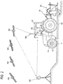
Fig. 2 is a side view of a tractor being an example of a work vehicle capable of unmanned travel. -
Fig. 3 is a functional block diagram of an exemplary control system in the master work vehicle. -
Fig. 4 is a view of an exemplary data flow in a process of displaying a message on work and travel information. -
Fig. 5 is a schematic view of an exemplary first form for discrimination between a master state message and a slave state message. -
Fig. 6 is a schematic view of an exemplary second form for discrimination between the master state message and the slave state message. -
Fig. 7 is a schematic view of an exemplary third form for discrimination between the master state message and the slave state message. -
Fig. 8 is a schematic view of an exemplary fourth form for discrimination between the master message and the slave message. - With reference to the drawings, a description will be given of a master work vehicle according to an embodiment of the present invention, the master work vehicle being configured to perform work in cooperation with a slave work vehicle capable of unmanned automatic travel. In this embodiment, the slave work vehicle and the master work vehicle correspond to tractors being work vehicles that may be substantially equal in function to each other. Each of the slave work device and the master work device may be equipped with a work device that is mounted to the back side of a vehicle body thereof. Each of the slave work device and the master work device may perform work (cultivating work in this embodiment) along a route that is set for a field being work land.
- In cooperative cultivating work illustrated in
Fig. 1 , of the two tractors, a slave tractor (hereinafter referred to as "slave work vehicle") that is a tractor prefixed with a word "slave" precedes and a master tractor (hereinafter, referred to as "master work vehicle") that is a tractor prefixed with a word "master" follows the slave work vehicle so as to cultivate a region slightly overlapping with a region cultivated by the preceding slave work vehicle. As a matter of course, the master work vehicle may precede, and the slave work vehicle may follow the master work vehicle. Alternatively, the slave work vehicle and the master work vehicle may perform work and travel on different parcels of a field independently of each other. The field illustrated inFig. 1 is divided into a central work land CL at the center of the field, and a headland HL on the periphery of the central work land CL, the headland HL being specified by ridges. Each work vehicle travels straight along a target route that is set in advance on the central work land CL. After arriving at the headland HL, each work vehicle turns around and travels straight again on the central work land CL. Finally, one or both of the work vehicles travels or travel on the headland HL. - The two work vehicles are capable of automatic travel along a set target route. The two work vehicles may take cooperative travel modes such as a first cooperative travel mode, a second cooperative travel mode, and a third cooperative travel mode. In the first cooperative travel mode, the master work vehicle travels manually by a driver-administrator riding therein while the slave work vehicle travels automatically. In the second cooperative travel mode, both the master work vehicle and the slave work vehicle travel automatically, and an observer rides in the master work vehicle. In the third cooperative travel mode, both the master work vehicle and the slave work vehicle travel automatically in an unmanned manner, and the observer observes work and travel states of the respective master work vehicle and slave work vehicle at the outside of the master work vehicle. In any case, the observer may issue a basic command such as an emergency stop of the master work vehicle and slave work vehicle.
- In this embodiment, the master work vehicle and the slave work vehicle may be tractors substantially equal in configuration to each other. As illustrated in
Fig. 2 , in the work vehicle, acockpit section 20 may be disposed at a center of avehicle body 10 supported byfront wheels 11 andrear wheels 12. A cultivatingdevice 30 of a rotary type being a work device may be mounted to the back side of thevehicle body 10 with alifting mechanism 31 of a hydraulic type. Thefront wheels 11 may serve as driving wheels. A traveling direction of the tractor may be changed when a steering angle is changed by asteering mechanism 13. Thesteering mechanism 13 may include asteering motor 14 for automatic steering. In manual travel, thefront wheels 11 may be steered using asteering wheel 22 disposed in thecockpit section 20. In this embodiment, a general-purpose terminal device 6 constituted of a tablet computer may be attached to a cradle mounted on a cockpit in thecockpit section 20. The general-purpose terminal device 6 has a wireless data transmission function. Even when an administrator detaches the general-purpose terminal device 6 from the cradle to take the general-purpose terminal device 6 out of the work vehicle, the general-purpose terminal device 6 enables the exchange of data by communications with a control system in the tractor. The general-purpose terminal device 6 has a function of giving information to a driver or an administrator and a function of receiving information from the driver or the administrator. - Also in this embodiment, as illustrated in
Fig. 2 , each of the master work vehicle and the slave work vehicle may employ a real time kinematic-global positioning system (RTK-GPS) method as a satellite positioning system. The satellite positioning system includes a satellite positioningbase station unit 9B and an on-vehiclesatellite positioning unit 9A each being a basic constituent element. The satellite positioningbase station unit 9B may be installed near the field. The satellite positioningbase station unit 9B may generate correction data based on position coordinates being a parameter indicative of a position of the satellite positioningbase station unit 9B and radio waves from satellites AS. The satellite positioningbase station unit 9B then transmits the correction data to the on-vehiclesatellite positioning unit 9A. A satellite antenna may be mounted on a ceiling region of acabin 21 of the tractor to receive a global navigation satellite system (GNSS) signal (including a global positioning system (GPS) signal). For complementation of satellite navigation using the satellite positioning system, the on-vehiclesatellite positioning unit 9A may be combined with an inertial navigation module including a gyro/acceleration sensor and a magnetic azimuth sensor. The inertial navigation module may be installed at a place different from a place where the on-vehiclesatellite positioning unit 9A is installed. -
Fig. 3 is a functional block diagram of the control system in the work vehicle. Acontrol unit 5 is a core element of the control system and may include an output processing module 7 and aninput processing module 8 as an input/output interface. Awireless module 70 is operative by a plurality of communication methods and is connected to thecontrol unit 5. Thewireless module 70 may establish wireless communications with different wireless communication instruments. Thewireless module 70 may also establish wireless communications with awireless module 70 of another work vehicle. Thewireless module 70 may be therefore used for data exchange between work vehicles (i.e., a master work vehicle and a slave work vehicle) and for data exchange with a general-purpose terminal device 6 removed from a work vehicle, at the outside of the work vehicle. As illustrated inFig. 3 , thecontrol unit 5 may be connected to the general-purpose terminal device 6 and the on-vehiclesatellite positioning unit 9A via, for example, an on-vehicle local area network (LAN). The on-vehiclesatellite positioning unit 9A is a vehicle-side constituent element of the satellite positioning system. - The output processing module 7 may be connected to
vehicle travel instruments 71 andwork device instruments 72. Thevehicle travel instruments 71 may include control instruments for vehicle travel, such as an engine control instrument, a transmission control instrument, a braking control instrument, and a steering control instrument. Thework device instruments 72 may include, for example, a power control instrument such as a power take-off (PTO) clutch for control of power transmission to the cultivatingdevice 30, and a lifting cylinder control instrument of thelifting mechanism 31 lifting up and down the cultivatingdevice 30. - The
input processing module 8 may be connected to, for example,travel system sensors 81,work system sensors 82, and a travel mode switchingtooling tool 83. The travelmode switching tool 83 is a switch for selecting one of an automatic travel mode in which the work vehicle travels by automatic steering and a manual steering mode in which the work vehicle travels by manual steering. For example, when the driver actuates the travelmode switching tool 83 at the time of travel in the automatic steering mode, the work vehicle is switched to travel by manual steering. On the other hand, when the driver actuates the travelmode switching tool 83 at the time of travel in the manual steering, the work vehicle is switched to travel by automatic steering. Thetravel system sensors 81 include sensors to detect states of operating tools such as an engine speed adjuster, an accelerator pedal, a brake pedal, and thesteering wheel 22. Thework system sensors 82 include sensors to detect a driving state and an orientation of the cultivatingdevice 30. - The
control unit 5 may include a work andtravel control module 50, aposition calculation module 57, and a work and travel stateinformation generation module 58. Theposition calculation module 57 may successively receive positioning data from the on-vehiclesatellite positioning unit 9A, and calculate a current position being a coordinate position (i.e., map coordinates or field coordinates) of thevehicle body 10, based on the positioning data. - The work and
travel control module 50 may include atravel control module 51, awork control module 52, anengine control module 53, an automatic work and travelcommand module 54, aroute setting module 55, and a cooperativetravel management module 56. Thetravel control module 51 may control thevehicle travel instruments 71 such as thesteering motor 14. The work vehicle is preferably capable of both the automatic travel (automatic steering) and the manual travel (manual steering). Thetravel control module 51 therefore may have a manual travel control function and an automatic travel control function. Thetravel control module 51 performs the manual travel control function to control thevehicle travel instruments 71 based on operations by the driver. Thetravel control module 51 performs the automatic travel control function to control thevehicle travel instruments 71 based on automatic steering commands from the automatic work and travelcommand module 54. Thework control module 52 may transmit work control signals to thework device instruments 72 to control the movements of the cultivatingdevice 30. Theengine control module 53 may transmit an engine control signal to an engine operating instrument. - The
route setting module 55 may receive field information and read contour data of the field from the field information to generate and set an appropriate route on the field. The route may be generated based on basic initial parameters given by the driver or the observer. Alternatively, theroute setting module 55 may download a route that is generated by a different computer and set the route. The route generated by theroute setting module 55 or the route acquired through the download may be developed onto a memory and may be set at a target route in the automatic travel. Also in the manual travel, the route may be used for guidance in order that the work vehicle travels along the route. - The automatic work and travel
command module 54 may calculate a directional deviation and a positional deviation between a route set at a target route by theroute setting module 55 and a current position calculated by theposition calculation module 57. The automatic work and travelcommand module 54 may then generate automatic steering commands for resolving the directional deviation and positional deviation, and may issue the automatic steering commands to thetravel control module 51. - In cooperative work with another cooperating work vehicle (i.e., a master work vehicle or a slave work vehicle), the cooperative
travel management module 56 may issue a request for generation and setting of a route to theroute setting module 55 so that theroute setting module 55 generates and sets the route, based on a cooperative travel pattern while taking a route of the other cooperating work vehicle into consideration. The cooperativetravel management module 56 may have a function of acquiring a travel state and a work state of the other cooperating tractor to control the work and travel of the other cooperating tractor, and/or a function of undergoing control by the other cooperating work vehicle as to the work and travel. - The work and travel state
information generation module 58 may generate work and travel state information indicative of the work and travel state of the work vehicle. The work and travel state information is referred to as master work and travel state information when the work vehicle is a master work vehicle. On the other hand, the work and travel state information is referred to as slave work and travel state information when the work vehicle is a slave work vehicle. The work and travel stateinformation generation module 58 generates the work and travel state information, based on detection data and control data, for example. The work and travel stateinformation generation module 58 may receive the detection data from thetravel system sensors 81 and thework system sensors 82 through theinput processing module 8. The control data is handled by the work andtravel control module 50. The work and travel state information may contain warning information to the driver or the observer. Examples of the warning information include: inclination of thevehicle body 10 beyond a permissive level; positional deviation of a current position from a target route beyond a permissible range; engine trouble such as overheating; fuel exhaustion; and battery exhaustion. When the warning information is generated, the driver or the observer is notified of the waning information. If necessary, the driver or the observer halts thevehicle body 10, stops the engine, and ceases the automatic travel. - The work and travel state information generated by the work and travel state
information generation module 58 may be transferred to the general-purpose terminal device 6 that functions as a display device in this embodiment. The general-purpose terminal device 6 displays various kinds of information, for the driver and the administrator. - The general-
purpose terminal device 6 may be substantially a computer having a wireless communication function, like a tablet computer. The general-purpose terminal device 6 may include atouch panel 60, aloudspeaker 67, an input/output processing module 61, and the like as standard functions. In addition, the general-purpose terminal device 6 may have installed therein a computer program constructing amessage management module 62. Themessage management module 62 may include amessage preparation module 63 and anotification control module 64. - The
message preparation module 63 may receive work and travel state information generated by the work and travel stateinformation generation module 58 of the slave work vehicle, from the slave work vehicle by wireless communications. Themessage preparation module 63 then prepares a slave state message describing a state of the slave work vehicle, from the work information state information. Themessage preparation module 63 may also receive work and travel state information generated by the work and travel stateinformation generation module 58 of the work vehicle (i.e., the master work vehicle). Themessage preparation module 63 then prepares a master state message describing a state of the work vehicle (i.e., the master work vehicle), from the work information state information. For example, when the warning information indicates that thevehicle body 10 is inclined beyond the permissive level, themessage preparation module 63 prepares a state message indicating "slave work vehicle (or master work vehicle) is halted because of abnormal inclination." In response to this, the state message may be confirmed by the driver or the observer. - The
notification control module 64 may include a displaydata generation module 65. The displaydata generation module 65 generates display data of a state message (e.g., a master state message or a slave state message) prepared by themessage preparation module 63, and then transmits the display data, for example to thetouch panel 60. Thetouch panel 60 thus displays on its screen a message corresponding to the display data. Thenotification control module 64 preferably makes the slave state message to be displayed on the screen clearly indicate that the slave state message concerns the slave work vehicle. Thenotification control module 64 also preferably makes the master state message to be displayed on the screen clearly indicate that the master state message concerns the master work vehicle. To this end, additional information is added to the slave state message and the master state message, for discrimination between the slave state message and the master state message. - In this embodiment, examples of the additional information include, but are not limited to, visual information that stimulates vision and auditory information that stimulates audition. The display
data generation module 65 generates various kinds of visual information as will be described later. The auditory information in this embodiment refers for example sound data of different timbre. A sounddata generation module 66 may generate sound data to be assigned to the master work vehicle and sound data to be assigned to the slave work vehicle. Alternatively, the sounddata generation module 66 may have these pieces of sound data that have been recorded thereon in advance. - The sound
data generation module 66 may generate sound data of a state message prepared by themessage preparation module 63, in the format of voice data. The driver or the observer may be notified of the state message by voice through theloudspeaker 67. - With reference to
Fig. 4 , next, a description will be given of data flow in an exemplary process of displaying a state message on a screen. In this embodiment, one master work vehicle and two slave work vehicles (i.e., a first slave work vehicle and a second slave work vehicle) participate in cooperative work. - In the master work vehicle, work and travel information generated by the work and travel state
information generation module 58 is sent to the general-purpose terminal device 6, based on, for example, a sensor signal. The work and travel information is preferably added with a code (e.g., "master" inFig. 4 ) for identifying a source. The work and travel information may be therefore recorded in a master memory area of a work and travelinformation memory 620 assigned to the memory of the general-purpose terminal device 6. - Also in the slave work vehicle, likewise, work and travel information generated by the work and travel state
information generation module 58 is sent to the general-purpose terminal device 6 of the master work vehicle, via thewireless module 70. The work and travel information is preferably added with a code (e.g., "first-slave" or "second-slave" inFig. 4 ) for identifying a source. The work and travel information may be therefore recorded in a first-slave memory area or a second-slave memory area of the work and travelinformation memory 620. - The
message preparation module 63 reads the work and travel information from the work and travelinformation memory 620. Themessage preparation module 63 then prepares a state message (i.e., a master state message, a first-slave state message, a second-slave state message) describing a state of the corresponding work vehicle. Themessage preparation module 63 gives the prepared state message to thenotification control module 64. - The
notification control module 64 generates display data of the received state message, and transmits the display data to thetouch panel 60. At this time, when for example auditory information is selected as additional information for identifying a state message source (e.g., the master work vehicle or the slave work vehicle), themessage preparation module 63 gives a source code indicative of the state message source to the sounddata generation module 66. The sounddata generation module 66 therefore transmits, to theloudspeaker 67, sound data of timbre for the source code. Theloudspeaker 67 thus outputs sound based on the sound data. When visual information is selected as additional information for identifying a state message source, display data in a visually identifiable format is generated as will be described later. Thetouch panel 60 displays the generated display data. Alternatively, thetouch panel 60 displays the state message while theloudspeaker 67 outputs the state message by voice. - With reference to
Figs. 5 to 8 , a description will be given of exemplary forms for identifying a state message source. - In the exemplary form illustrated in
Fig. 5 , the state message source is identified with sound of different timbre. When the state message source is the slave work vehicle, thetouch panel 60 displays the slave state message while theloudspeaker 67 outputs sound of first timbre, "beep, beep, beep". When the state message source is the master work vehicle, thetouch panel 60 displays the master state message while theloudspeaker 67 outputs sound of second timbre, "ding dong". - In the exemplary form illustrated in
Fig. 6 , a slave state message box and a master state message box are displayed on the screen in addition to the respective state messages. When the state message source is the slave work vehicle, the slave state message is displayed in the slave state message box. When the state message source is the master work vehicle, the master state message is displayed in the master state message box. This is effective when a display region for each state message is larger. - In the exemplary form illustrated in
Fig. 7 , the slave state message, of which the source is the slave work vehicle, is displayed with a first text color and a first background color. On the other hand, the master state message, of which the source is the master work vehicle, is displayed with a second text color and a second background color. The first text color is different from the second text color, and the first background color is different from the second background color. As a matter of course, only the first and second text colors may be different from each other. Alternatively, only the first and second background colors may be different from each other. - In the exemplary form illustrated in
Fig. 8 , the slave state message, of which the source is the slave work vehicle, is displayed in conjunction with a slave display item indicative of the slave work vehicle. In this embodiment, an icon of a word "slave" is displayed as the slave display item in front of the slave state message. On the other hand, the master state message, of which the source is the master work vehicle, is displayed in conjunction with a master display item indicative of the master work vehicle. In this embodiment, an icon of a word "master" is displayed as the master display item in front of the master state message. The slave display item and the master display item may be graphical images of various designs. The displaydata generation module 65 combines the slave state message with the slave display item to generate slave display data. In addition, the displaydata generation module 65 combines the master state message with the master display item to generate master display data. - Various forms for clearly identifying a state message source, such as those illustrated in
Figs. 7 and 8 , may be selected based on the details of the state message or may be selected in accordance with observer's preference. Alternatively, two or more forms may be combined. - It should be noted that the configuration disclosed in the foregoing embodiment (including the other embodiments; the same applies hereinafter) may be applied in conjunction with the configurations disclosed in the other embodiments as long as no contradiction arises. The embodiments disclosed herein are merely illustrative. The present invention therefore is not limited to the embodiments, and the embodiments may be appropriately modified without departing from the scope of the present invention.
-
- (1) Since the
message management module 62 is constructed in the general-purpose terminal device 6, the state message may be confirmed at the outside of the work vehicle through the general-purpose terminal device 6 removed from the work vehicle. Instead of this configuration, themessage management module 62 may be constructed in thecontrol unit 5 with the general-purpose terminal device 6 disabled to be removed from the work vehicle. In this case, a display, such as a liquid crystal display, of the work vehicle is used for displaying a state message. - (2) The function modules illustrated in
Figs. 3 and4 are mainly segmented for the sake of description. In practical use, the respective function modules may be integrated with one another or each functional module may be further divided into multiple function modules. - (3) In the foregoing embodiment, the tractor equipped with the cultivating
device 30 being a work device is described as an example of a work vehicle. The present invention is alternatively applicable to, in addition to the tractor, various work vehicles such as construction work vehicles and agricultural work vehicles including a rice-planting machine, a fertilizing machine, and a combined harvester and thresher. In addition, multiple work vehicles for cooperative work are not necessary the same in type as one another. For example, one of the work vehicles may be a combined harvester and thresher, and another one of the work vehicles may be a tractor. - (4) In the foregoing embodiment, the master work vehicle performs the cooperative work in cooperation with the slave work vehicle. It is needless to say that the master work vehicle is also used to perform work solely. In displaying a state message, it is therefore unnecessary to discriminate the master work vehicle from the slave work vehicle. A state message of which the source is the master work vehicle is always displayed. However, the state message of which the source is the master work vehicle is may be displayed in a highlighted manner as described above. In addition, the state message may be notified by voice. Alternatively, the state message may be notified by voice without being displayed. In cases where the observer uses the general-
purpose terminal device 6 at the outside of the work vehicle, the observer may listen to the state message through a canalphone or a headphone so as to shut off from surrounding noise. - The present invention is applicable to a work vehicle configured to perform work in cooperation with a work vehicle capable of unmanned automatic travel and to establish wireless data communications with the work vehicle capable of unmanned automatic travel.
- The subject matter described in the application can be implemented as a method or as a system, possibly in the form of one or more computer program products. The subject matter described in the application can be implemented in a data signal or on a machine readable medium, where the medium is embodied in one or more information carriers, such as a CD-ROM, a DVD-ROM, a semiconductor memory, or a hard disk. Such computer program products may cause a data processing apparatus to perform one or more operations described in the application.
- In addition, subject matter described in the application can also be implemented as a system including a processor, and a memory coupled to the processor. The memory may encode one or more programs to cause the processor to perform one or more of the methods described in the application. Further subject matter described in the application can be implemented using various machines.
-
- 5: control unit
- 50: work and travel control module
- 51: travel control module
- 52: work control module
- 53: engine control module
- 54: automatic work and travel command module
- 55: route setting module
- 56: cooperative travel management module
- 57: position calculation module
- 58: work and travel state information generation module
- 6: general-purpose terminal device
- 60: touch panel (an example of a display device)
- 61: input/output processing module
- 62: message management module
- 620: work and travel information memory
- 63: message preparation module
- 64: notification control module
- 65: display data generation module
- 66: sound data generation module
- 67: loudspeaker
- 70: wireless module
- 81: travel system sensors
- 82: work system sensors
Claims (8)
- A master work vehicle configured to perform work in cooperation with a slave work vehicle capable of unmanned automatic travel,
the master work vehicle comprising:a wireless module (70) configured to receive, from the slave work vehicle, slave work and travel state information indicative of a work and travel state of the slave work vehicle;a work and travel state information generation module (58) configured to generate master work and travel state information indicative of a work and travel state of the master work vehicle;a display device (60) configured to display various kinds of information;a message preparation module (63) configured to prepare a slave state message describing a state of the slave work vehicle, from the slave work and travel state information, and to prepare a master state message describing a state of the master work vehicle, from the master work and travel state information; anda notification control module (64) configured to control the display device (60) to display the slave state message and the master state message, and to add additional information to the slave state message and the master state message, for discrimination between the slave state message and the master state message. - The master work vehicle according to claim 1, wherein
the slave state message is displayed on the display device (60) in conjunction with sound of first timbre, and
the master state message is displayed on the display device (60) in conjunction with sound of second timbre different from the first timbre. - The master work vehicle according to claim 1 or 2, wherein
a slave state message box in which the slave state message is to be displayed and a master state message box in which the master state message is to be displayed are prepared for the notification control module (64). - The master work vehicle according to any one of claims 1 to 3, wherein
the slave state message is displayed with at least one of a first text color and a first background color, and
the master state message is displayed with at least one of a second text color and a second background color respectively different from the first text color and the first background color. - The master work vehicle according to any one of claims 1 to 4, wherein
a slave display item indicative of the slave work vehicle and a master display item indicative of the master work vehicle are prepared for the notification control module (64),
slave display data is generated by a combination of the slave state message with the slave display item, and
master display data is generated by a combination of the master state message with the master display item. - A method for operating a master work vehicle and a slave work vehicle, the master work vehicle being configured to perform work in cooperation with a slave work vehicle capable of unmanned automatic travel, the method comprising:receiving slave work and travel state information indicative of a work and travel state of the slave work vehicle;generating master work and travel state information indicative of a work and travel state of the master work vehicle;preparing a slave state message describing a state of the slave work vehicle, from the slave work and travel state information and a master state message describing a state of the master work vehicle, from the master work and travel state information; andcontrolling a display device (60) to display the slave state message and the master state message, and to add additional information to the slave state message and the master state message, for discrimination between the slave state message and the master state message.
- A computer program product comprising computer readable instructions that when loaded and run on a computer comprised in a work vehicle, cause the computer to perform the method of claim 6.
- A system for operating a master work vehicle and a slave work vehicle, the master work vehicle being configured to perform work in cooperation with a slave work vehicle capable of unmanned automatic travel, the system comprising:a display device (60);a control unit (5) configured to execute the method according to claim 6.
Applications Claiming Priority (1)
| Application Number | Priority Date | Filing Date | Title |
|---|---|---|---|
| JP2017105911A JP6832793B2 (en) | 2017-05-29 | 2017-05-29 | A parent work vehicle that works in cooperation with a child work vehicle |
Publications (2)
| Publication Number | Publication Date |
|---|---|
| EP3410247A1 true EP3410247A1 (en) | 2018-12-05 |
| EP3410247B1 EP3410247B1 (en) | 2020-02-19 |
Family
ID=62235820
Family Applications (1)
| Application Number | Title | Priority Date | Filing Date |
|---|---|---|---|
| EP18173563.0A Active EP3410247B1 (en) | 2017-05-29 | 2018-05-22 | Master work vehicle performing work in cooperation with slave work vehicle |
Country Status (4)
| Country | Link |
|---|---|
| US (1) | US10905042B2 (en) |
| EP (1) | EP3410247B1 (en) |
| JP (1) | JP6832793B2 (en) |
| CN (1) | CN108933999B (en) |
Families Citing this family (8)
| Publication number | Priority date | Publication date | Assignee | Title |
|---|---|---|---|---|
| US11178712B2 (en) * | 2018-10-02 | 2021-11-16 | Deere & Company | Systems and methods to establish secure vehicle networks |
| JP6897697B2 (en) * | 2019-02-25 | 2021-07-07 | 井関農機株式会社 | Parallel work system for transplant machines |
| JP7288417B2 (en) | 2020-03-31 | 2023-06-07 | 本田技研工業株式会社 | AUTONOMOUS WORK SYSTEM, AUTONOMOUS WORK SETTING METHOD AND PROGRAM |
| JP2022155101A (en) * | 2021-03-30 | 2022-10-13 | 本田技研工業株式会社 | Arithmetic unit and work machine |
| IL283080B2 (en) * | 2021-05-10 | 2024-03-01 | Plasan Sasa Ltd | A controllable electric vehicle and a control system for it |
| JP7748910B2 (en) * | 2022-04-13 | 2025-10-03 | 株式会社クボタ | Field work vehicle |
| JP7580423B2 (en) * | 2022-04-22 | 2024-11-11 | 株式会社小松製作所 | Work site management system and work site management method |
| FI4286609T3 (en) * | 2022-06-01 | 2025-04-05 | Contelec Ag | System comprising multiple inertial measurement units |
Citations (4)
| Publication number | Priority date | Publication date | Assignee | Title |
|---|---|---|---|---|
| US20020165649A1 (en) * | 2001-05-07 | 2002-11-07 | The Board Of Trustees Of The Leland Stanford Junior University | Method and apparatus for vehicle control, navigation and positioning |
| US20120215381A1 (en) * | 2011-02-18 | 2012-08-23 | Guoping Wang | System and method for synchronized control of a harvester and transport vehicle |
| JP2015188351A (en) | 2014-03-27 | 2015-11-02 | 株式会社クボタ | Work vehicle coordination system |
| JP2015221614A (en) | 2014-05-22 | 2015-12-10 | ヤンマー株式会社 | Monitoring device |
Family Cites Families (7)
| Publication number | Priority date | Publication date | Assignee | Title |
|---|---|---|---|---|
| JP4310632B2 (en) * | 2003-11-07 | 2009-08-12 | 日立建機株式会社 | Construction machine display device |
| JP2005238962A (en) * | 2004-02-26 | 2005-09-08 | Nippon Seiki Co Ltd | Vehicle information providing device |
| US9002591B2 (en) * | 2011-02-18 | 2015-04-07 | Cnh Industrial America Llc | Harvester spout control system and method |
| KR102113297B1 (en) * | 2012-09-26 | 2020-05-21 | 가부시끼 가이샤 구보다 | Ground work vehicle, ground work vehicle management system, and ground work information display method |
| JP6021717B2 (en) * | 2013-03-29 | 2016-11-09 | 株式会社クボタ | Work management support device and work management system |
| JP6219790B2 (en) * | 2014-07-29 | 2017-10-25 | 株式会社クボタ | Work vehicle coordination system |
| JP6384545B2 (en) * | 2015-02-13 | 2018-09-05 | ヤンマー株式会社 | Control system for autonomous work vehicle |
-
2017
- 2017-05-29 JP JP2017105911A patent/JP6832793B2/en active Active
-
2018
- 2018-04-26 CN CN201810383778.3A patent/CN108933999B/en active Active
- 2018-05-22 EP EP18173563.0A patent/EP3410247B1/en active Active
- 2018-05-24 US US15/987,905 patent/US10905042B2/en active Active
Patent Citations (4)
| Publication number | Priority date | Publication date | Assignee | Title |
|---|---|---|---|---|
| US20020165649A1 (en) * | 2001-05-07 | 2002-11-07 | The Board Of Trustees Of The Leland Stanford Junior University | Method and apparatus for vehicle control, navigation and positioning |
| US20120215381A1 (en) * | 2011-02-18 | 2012-08-23 | Guoping Wang | System and method for synchronized control of a harvester and transport vehicle |
| JP2015188351A (en) | 2014-03-27 | 2015-11-02 | 株式会社クボタ | Work vehicle coordination system |
| JP2015221614A (en) | 2014-05-22 | 2015-12-10 | ヤンマー株式会社 | Monitoring device |
Non-Patent Citations (1)
| Title |
|---|
| DEERE & COMPANY: "John Deere Precision Ag Technology", 31 October 2015 (2015-10-31), XP055423180, Retrieved from the Internet <URL:http://www.kibbleeq.com/webres/File/Precision Ag/JD Precision Ag Brochure.pdf> [retrieved on 20171109] * |
Also Published As
| Publication number | Publication date |
|---|---|
| JP6832793B2 (en) | 2021-02-24 |
| JP2018198583A (en) | 2018-12-20 |
| US10905042B2 (en) | 2021-02-02 |
| US20180338408A1 (en) | 2018-11-29 |
| CN108933999B (en) | 2023-05-16 |
| CN108933999A (en) | 2018-12-04 |
| EP3410247B1 (en) | 2020-02-19 |
Similar Documents
| Publication | Publication Date | Title |
|---|---|---|
| EP3410247B1 (en) | Master work vehicle performing work in cooperation with slave work vehicle | |
| JP7069364B2 (en) | Work vehicle | |
| EP3352036B1 (en) | Work vehicle wireless management system and method for controlling work traveling of a plurality of work vehicles | |
| JP7550281B2 (en) | Autonomous driving system and method | |
| US20180215393A1 (en) | Autonomously traveling work vehicle | |
| EP4218379A1 (en) | Automatic traveling system, automatic traveling method, and automatic traveling program | |
| CN108205316B (en) | Automatic driving operation vehicle | |
| WO2020129704A1 (en) | Travel working machine | |
| JP6925133B2 (en) | Satellite radio sensitivity distribution management system for work platforms | |
| JP2020099224A (en) | Traveling work machine | |
| CN108200782B (en) | Automatic driving operation vehicle | |
| JP2024177365A (en) | Autonomous Driving System | |
| JP6879896B2 (en) | Satellite positioning system for work platforms | |
| US20230280474A1 (en) | Positioning Device, Work Vehicle, Positioning Method, And Positioning Program | |
| JP2024053067A (en) | Autonomous driving system and method | |
| CN109508006A (en) | A kind of automated driving system of the autocrane based on Beidou | |
| JP6945353B2 (en) | Self-driving work vehicle | |
| JP2022096949A (en) | Remote control device for plurality of work machine | |
| JP6815279B2 (en) | Work driving function diagnostic device | |
| JP7378522B2 (en) | Work vehicle wireless management system | |
| JP2022010873A (en) | Control system for work vehicle | |
| JP7055189B2 (en) | Work driving function diagnostic device | |
| JP2021002397A (en) | Work management system | |
| JP2022010872A (en) | Control system for work vehicle | |
| US20260137019A1 (en) | Operation control method, operation control program, and operation control system |
Legal Events
| Date | Code | Title | Description |
|---|---|---|---|
| PUAI | Public reference made under article 153(3) epc to a published international application that has entered the european phase |
Free format text: ORIGINAL CODE: 0009012 |
|
| STAA | Information on the status of an ep patent application or granted ep patent |
Free format text: STATUS: THE APPLICATION HAS BEEN PUBLISHED |
|
| AK | Designated contracting states |
Kind code of ref document: A1 Designated state(s): AL AT BE BG CH CY CZ DE DK EE ES FI FR GB GR HR HU IE IS IT LI LT LU LV MC MK MT NL NO PL PT RO RS SE SI SK SM TR |
|
| AX | Request for extension of the european patent |
Extension state: BA ME |
|
| STAA | Information on the status of an ep patent application or granted ep patent |
Free format text: STATUS: REQUEST FOR EXAMINATION WAS MADE |
|
| 17P | Request for examination filed |
Effective date: 20190516 |
|
| RBV | Designated contracting states (corrected) |
Designated state(s): AL AT BE BG CH CY CZ DE DK EE ES FI FR GB GR HR HU IE IS IT LI LT LU LV MC MK MT NL NO PL PT RO RS SE SI SK SM TR |
|
| GRAP | Despatch of communication of intention to grant a patent |
Free format text: ORIGINAL CODE: EPIDOSNIGR1 |
|
| STAA | Information on the status of an ep patent application or granted ep patent |
Free format text: STATUS: GRANT OF PATENT IS INTENDED |
|
| INTG | Intention to grant announced |
Effective date: 20190920 |
|
| GRAS | Grant fee paid |
Free format text: ORIGINAL CODE: EPIDOSNIGR3 |
|
| GRAA | (expected) grant |
Free format text: ORIGINAL CODE: 0009210 |
|
| STAA | Information on the status of an ep patent application or granted ep patent |
Free format text: STATUS: THE PATENT HAS BEEN GRANTED |
|
| AK | Designated contracting states |
Kind code of ref document: B1 Designated state(s): AL AT BE BG CH CY CZ DE DK EE ES FI FR GB GR HR HU IE IS IT LI LT LU LV MC MK MT NL NO PL PT RO RS SE SI SK SM TR |
|
| REG | Reference to a national code |
Ref country code: CH Ref legal event code: EP |
|
| REG | Reference to a national code |
Ref country code: DE Ref legal event code: R096 Ref document number: 602018002488 Country of ref document: DE |
|
| REG | Reference to a national code |
Ref country code: AT Ref legal event code: REF Ref document number: 1235674 Country of ref document: AT Kind code of ref document: T Effective date: 20200315 |
|
| REG | Reference to a national code |
Ref country code: IE Ref legal event code: FG4D |
|
| REG | Reference to a national code |
Ref country code: NL Ref legal event code: MP Effective date: 20200219 |
|
| PG25 | Lapsed in a contracting state [announced via postgrant information from national office to epo] |
Ref country code: FI Free format text: LAPSE BECAUSE OF FAILURE TO SUBMIT A TRANSLATION OF THE DESCRIPTION OR TO PAY THE FEE WITHIN THE PRESCRIBED TIME-LIMIT Effective date: 20200219 Ref country code: NO Free format text: LAPSE BECAUSE OF FAILURE TO SUBMIT A TRANSLATION OF THE DESCRIPTION OR TO PAY THE FEE WITHIN THE PRESCRIBED TIME-LIMIT Effective date: 20200519 Ref country code: RS Free format text: LAPSE BECAUSE OF FAILURE TO SUBMIT A TRANSLATION OF THE DESCRIPTION OR TO PAY THE FEE WITHIN THE PRESCRIBED TIME-LIMIT Effective date: 20200219 |
|
| REG | Reference to a national code |
Ref country code: LT Ref legal event code: MG4D |
|
| PG25 | Lapsed in a contracting state [announced via postgrant information from national office to epo] |
Ref country code: BG Free format text: LAPSE BECAUSE OF FAILURE TO SUBMIT A TRANSLATION OF THE DESCRIPTION OR TO PAY THE FEE WITHIN THE PRESCRIBED TIME-LIMIT Effective date: 20200519 Ref country code: IS Free format text: LAPSE BECAUSE OF FAILURE TO SUBMIT A TRANSLATION OF THE DESCRIPTION OR TO PAY THE FEE WITHIN THE PRESCRIBED TIME-LIMIT Effective date: 20200619 Ref country code: HR Free format text: LAPSE BECAUSE OF FAILURE TO SUBMIT A TRANSLATION OF THE DESCRIPTION OR TO PAY THE FEE WITHIN THE PRESCRIBED TIME-LIMIT Effective date: 20200219 Ref country code: SE Free format text: LAPSE BECAUSE OF FAILURE TO SUBMIT A TRANSLATION OF THE DESCRIPTION OR TO PAY THE FEE WITHIN THE PRESCRIBED TIME-LIMIT Effective date: 20200219 Ref country code: LV Free format text: LAPSE BECAUSE OF FAILURE TO SUBMIT A TRANSLATION OF THE DESCRIPTION OR TO PAY THE FEE WITHIN THE PRESCRIBED TIME-LIMIT Effective date: 20200219 Ref country code: GR Free format text: LAPSE BECAUSE OF FAILURE TO SUBMIT A TRANSLATION OF THE DESCRIPTION OR TO PAY THE FEE WITHIN THE PRESCRIBED TIME-LIMIT Effective date: 20200520 |
|
| PG25 | Lapsed in a contracting state [announced via postgrant information from national office to epo] |
Ref country code: NL Free format text: LAPSE BECAUSE OF FAILURE TO SUBMIT A TRANSLATION OF THE DESCRIPTION OR TO PAY THE FEE WITHIN THE PRESCRIBED TIME-LIMIT Effective date: 20200219 |
|
| PG25 | Lapsed in a contracting state [announced via postgrant information from national office to epo] |
Ref country code: ES Free format text: LAPSE BECAUSE OF FAILURE TO SUBMIT A TRANSLATION OF THE DESCRIPTION OR TO PAY THE FEE WITHIN THE PRESCRIBED TIME-LIMIT Effective date: 20200219 Ref country code: LT Free format text: LAPSE BECAUSE OF FAILURE TO SUBMIT A TRANSLATION OF THE DESCRIPTION OR TO PAY THE FEE WITHIN THE PRESCRIBED TIME-LIMIT Effective date: 20200219 Ref country code: RO Free format text: LAPSE BECAUSE OF FAILURE TO SUBMIT A TRANSLATION OF THE DESCRIPTION OR TO PAY THE FEE WITHIN THE PRESCRIBED TIME-LIMIT Effective date: 20200219 Ref country code: CZ Free format text: LAPSE BECAUSE OF FAILURE TO SUBMIT A TRANSLATION OF THE DESCRIPTION OR TO PAY THE FEE WITHIN THE PRESCRIBED TIME-LIMIT Effective date: 20200219 Ref country code: PT Free format text: LAPSE BECAUSE OF FAILURE TO SUBMIT A TRANSLATION OF THE DESCRIPTION OR TO PAY THE FEE WITHIN THE PRESCRIBED TIME-LIMIT Effective date: 20200712 Ref country code: SK Free format text: LAPSE BECAUSE OF FAILURE TO SUBMIT A TRANSLATION OF THE DESCRIPTION OR TO PAY THE FEE WITHIN THE PRESCRIBED TIME-LIMIT Effective date: 20200219 Ref country code: SM Free format text: LAPSE BECAUSE OF FAILURE TO SUBMIT A TRANSLATION OF THE DESCRIPTION OR TO PAY THE FEE WITHIN THE PRESCRIBED TIME-LIMIT Effective date: 20200219 Ref country code: EE Free format text: LAPSE BECAUSE OF FAILURE TO SUBMIT A TRANSLATION OF THE DESCRIPTION OR TO PAY THE FEE WITHIN THE PRESCRIBED TIME-LIMIT Effective date: 20200219 Ref country code: DK Free format text: LAPSE BECAUSE OF FAILURE TO SUBMIT A TRANSLATION OF THE DESCRIPTION OR TO PAY THE FEE WITHIN THE PRESCRIBED TIME-LIMIT Effective date: 20200219 |
|
| REG | Reference to a national code |
Ref country code: AT Ref legal event code: MK05 Ref document number: 1235674 Country of ref document: AT Kind code of ref document: T Effective date: 20200219 |
|
| REG | Reference to a national code |
Ref country code: DE Ref legal event code: R097 Ref document number: 602018002488 Country of ref document: DE |
|
| PLBE | No opposition filed within time limit |
Free format text: ORIGINAL CODE: 0009261 |
|
| STAA | Information on the status of an ep patent application or granted ep patent |
Free format text: STATUS: NO OPPOSITION FILED WITHIN TIME LIMIT |
|
| 26N | No opposition filed |
Effective date: 20201120 |
|
| PG25 | Lapsed in a contracting state [announced via postgrant information from national office to epo] |
Ref country code: IT Free format text: LAPSE BECAUSE OF FAILURE TO SUBMIT A TRANSLATION OF THE DESCRIPTION OR TO PAY THE FEE WITHIN THE PRESCRIBED TIME-LIMIT Effective date: 20200219 Ref country code: AT Free format text: LAPSE BECAUSE OF FAILURE TO SUBMIT A TRANSLATION OF THE DESCRIPTION OR TO PAY THE FEE WITHIN THE PRESCRIBED TIME-LIMIT Effective date: 20200219 Ref country code: MC Free format text: LAPSE BECAUSE OF FAILURE TO SUBMIT A TRANSLATION OF THE DESCRIPTION OR TO PAY THE FEE WITHIN THE PRESCRIBED TIME-LIMIT Effective date: 20200219 |
|
| PG25 | Lapsed in a contracting state [announced via postgrant information from national office to epo] |
Ref country code: SI Free format text: LAPSE BECAUSE OF FAILURE TO SUBMIT A TRANSLATION OF THE DESCRIPTION OR TO PAY THE FEE WITHIN THE PRESCRIBED TIME-LIMIT Effective date: 20200219 Ref country code: PL Free format text: LAPSE BECAUSE OF FAILURE TO SUBMIT A TRANSLATION OF THE DESCRIPTION OR TO PAY THE FEE WITHIN THE PRESCRIBED TIME-LIMIT Effective date: 20200219 |
|
| REG | Reference to a national code |
Ref country code: BE Ref legal event code: MM Effective date: 20200531 |
|
| PG25 | Lapsed in a contracting state [announced via postgrant information from national office to epo] |
Ref country code: LU Free format text: LAPSE BECAUSE OF NON-PAYMENT OF DUE FEES Effective date: 20200522 |
|
| PG25 | Lapsed in a contracting state [announced via postgrant information from national office to epo] |
Ref country code: IE Free format text: LAPSE BECAUSE OF NON-PAYMENT OF DUE FEES Effective date: 20200522 |
|
| PG25 | Lapsed in a contracting state [announced via postgrant information from national office to epo] |
Ref country code: BE Free format text: LAPSE BECAUSE OF NON-PAYMENT OF DUE FEES Effective date: 20200531 |
|
| REG | Reference to a national code |
Ref country code: CH Ref legal event code: PL |
|
| PG25 | Lapsed in a contracting state [announced via postgrant information from national office to epo] |
Ref country code: LI Free format text: LAPSE BECAUSE OF NON-PAYMENT OF DUE FEES Effective date: 20210531 Ref country code: CH Free format text: LAPSE BECAUSE OF NON-PAYMENT OF DUE FEES Effective date: 20210531 |
|
| PG25 | Lapsed in a contracting state [announced via postgrant information from national office to epo] |
Ref country code: TR Free format text: LAPSE BECAUSE OF FAILURE TO SUBMIT A TRANSLATION OF THE DESCRIPTION OR TO PAY THE FEE WITHIN THE PRESCRIBED TIME-LIMIT Effective date: 20200219 Ref country code: MT Free format text: LAPSE BECAUSE OF FAILURE TO SUBMIT A TRANSLATION OF THE DESCRIPTION OR TO PAY THE FEE WITHIN THE PRESCRIBED TIME-LIMIT Effective date: 20200219 Ref country code: CY Free format text: LAPSE BECAUSE OF FAILURE TO SUBMIT A TRANSLATION OF THE DESCRIPTION OR TO PAY THE FEE WITHIN THE PRESCRIBED TIME-LIMIT Effective date: 20200219 |
|
| PG25 | Lapsed in a contracting state [announced via postgrant information from national office to epo] |
Ref country code: MK Free format text: LAPSE BECAUSE OF FAILURE TO SUBMIT A TRANSLATION OF THE DESCRIPTION OR TO PAY THE FEE WITHIN THE PRESCRIBED TIME-LIMIT Effective date: 20200219 Ref country code: AL Free format text: LAPSE BECAUSE OF FAILURE TO SUBMIT A TRANSLATION OF THE DESCRIPTION OR TO PAY THE FEE WITHIN THE PRESCRIBED TIME-LIMIT Effective date: 20200219 |
|
| GBPC | Gb: european patent ceased through non-payment of renewal fee |
Effective date: 20220522 |
|
| PG25 | Lapsed in a contracting state [announced via postgrant information from national office to epo] |
Ref country code: GB Free format text: LAPSE BECAUSE OF NON-PAYMENT OF DUE FEES Effective date: 20220522 |
|
| REG | Reference to a national code |
Ref country code: DE Ref legal event code: R079 Ref document number: 602018002488 Country of ref document: DE Free format text: PREVIOUS MAIN CLASS: G05D0001020000 Ipc: G05D0001430000 |
|
| PGFP | Annual fee paid to national office [announced via postgrant information from national office to epo] |
Ref country code: DE Payment date: 20250402 Year of fee payment: 8 |
|
| PGFP | Annual fee paid to national office [announced via postgrant information from national office to epo] |
Ref country code: FR Payment date: 20250401 Year of fee payment: 8 |