EP3409984B1 - Distributeur à tiroir cylindrique - Google Patents
Distributeur à tiroir cylindrique Download PDFInfo
- Publication number
- EP3409984B1 EP3409984B1 EP18174671.0A EP18174671A EP3409984B1 EP 3409984 B1 EP3409984 B1 EP 3409984B1 EP 18174671 A EP18174671 A EP 18174671A EP 3409984 B1 EP3409984 B1 EP 3409984B1
- Authority
- EP
- European Patent Office
- Prior art keywords
- magnet
- piston
- permanent magnet
- force
- magnetic armature
- Prior art date
- Legal status (The legal status is an assumption and is not a legal conclusion. Google has not performed a legal analysis and makes no representation as to the accuracy of the status listed.)
- Active
Links
- 239000012530 fluid Substances 0.000 claims description 25
- 239000006096 absorbing agent Substances 0.000 claims description 6
- 230000035939 shock Effects 0.000 claims description 6
- 238000006073 displacement reaction Methods 0.000 claims description 3
- 230000005672 electromagnetic field Effects 0.000 claims description 2
- 230000001105 regulatory effect Effects 0.000 claims description 2
- XEEYBQQBJWHFJM-UHFFFAOYSA-N Iron Chemical compound [Fe] XEEYBQQBJWHFJM-UHFFFAOYSA-N 0.000 description 6
- 230000004907 flux Effects 0.000 description 6
- 229910052742 iron Inorganic materials 0.000 description 3
- 230000008901 benefit Effects 0.000 description 2
- 239000012141 concentrate Substances 0.000 description 2
- 238000010276 construction Methods 0.000 description 2
- 238000011161 development Methods 0.000 description 2
- 230000018109 developmental process Effects 0.000 description 2
- 230000000694 effects Effects 0.000 description 2
- 230000005284 excitation Effects 0.000 description 2
- 230000008859 change Effects 0.000 description 1
- 238000013016 damping Methods 0.000 description 1
- 230000001419 dependent effect Effects 0.000 description 1
- 238000005265 energy consumption Methods 0.000 description 1
- 230000002496 gastric effect Effects 0.000 description 1
- 238000001746 injection moulding Methods 0.000 description 1
- 238000009434 installation Methods 0.000 description 1
- 230000005415 magnetization Effects 0.000 description 1
- 239000000463 material Substances 0.000 description 1
- 230000036316 preload Effects 0.000 description 1
- 230000007704 transition Effects 0.000 description 1
Images


Classifications
-
- F—MECHANICAL ENGINEERING; LIGHTING; HEATING; WEAPONS; BLASTING
- F16—ENGINEERING ELEMENTS AND UNITS; GENERAL MEASURES FOR PRODUCING AND MAINTAINING EFFECTIVE FUNCTIONING OF MACHINES OR INSTALLATIONS; THERMAL INSULATION IN GENERAL
- F16F—SPRINGS; SHOCK-ABSORBERS; MEANS FOR DAMPING VIBRATION
- F16F9/00—Springs, vibration-dampers, shock-absorbers, or similarly-constructed movement-dampers using a fluid or the equivalent as damping medium
- F16F9/32—Details
- F16F9/34—Special valve constructions; Shape or construction of throttling passages
-
- F—MECHANICAL ENGINEERING; LIGHTING; HEATING; WEAPONS; BLASTING
- F16—ENGINEERING ELEMENTS AND UNITS; GENERAL MEASURES FOR PRODUCING AND MAINTAINING EFFECTIVE FUNCTIONING OF MACHINES OR INSTALLATIONS; THERMAL INSULATION IN GENERAL
- F16K—VALVES; TAPS; COCKS; ACTUATING-FLOATS; DEVICES FOR VENTING OR AERATING
- F16K31/00—Actuating devices; Operating means; Releasing devices
- F16K31/02—Actuating devices; Operating means; Releasing devices electric; magnetic
- F16K31/06—Actuating devices; Operating means; Releasing devices electric; magnetic using a magnet, e.g. diaphragm valves, cutting off by means of a liquid
- F16K31/0644—One-way valve
- F16K31/0668—Sliding valves
-
- F—MECHANICAL ENGINEERING; LIGHTING; HEATING; WEAPONS; BLASTING
- F16—ENGINEERING ELEMENTS AND UNITS; GENERAL MEASURES FOR PRODUCING AND MAINTAINING EFFECTIVE FUNCTIONING OF MACHINES OR INSTALLATIONS; THERMAL INSULATION IN GENERAL
- F16K—VALVES; TAPS; COCKS; ACTUATING-FLOATS; DEVICES FOR VENTING OR AERATING
- F16K31/00—Actuating devices; Operating means; Releasing devices
- F16K31/02—Actuating devices; Operating means; Releasing devices electric; magnetic
- F16K31/06—Actuating devices; Operating means; Releasing devices electric; magnetic using a magnet, e.g. diaphragm valves, cutting off by means of a liquid
- F16K31/0675—Electromagnet aspects, e.g. electric supply therefor
-
- F—MECHANICAL ENGINEERING; LIGHTING; HEATING; WEAPONS; BLASTING
- F16—ENGINEERING ELEMENTS AND UNITS; GENERAL MEASURES FOR PRODUCING AND MAINTAINING EFFECTIVE FUNCTIONING OF MACHINES OR INSTALLATIONS; THERMAL INSULATION IN GENERAL
- F16K—VALVES; TAPS; COCKS; ACTUATING-FLOATS; DEVICES FOR VENTING OR AERATING
- F16K31/00—Actuating devices; Operating means; Releasing devices
- F16K31/02—Actuating devices; Operating means; Releasing devices electric; magnetic
- F16K31/06—Actuating devices; Operating means; Releasing devices electric; magnetic using a magnet, e.g. diaphragm valves, cutting off by means of a liquid
- F16K31/0686—Braking, pressure equilibration, shock absorbing
- F16K31/0693—Pressure equilibration of the armature
-
- F—MECHANICAL ENGINEERING; LIGHTING; HEATING; WEAPONS; BLASTING
- F16—ENGINEERING ELEMENTS AND UNITS; GENERAL MEASURES FOR PRODUCING AND MAINTAINING EFFECTIVE FUNCTIONING OF MACHINES OR INSTALLATIONS; THERMAL INSULATION IN GENERAL
- F16K—VALVES; TAPS; COCKS; ACTUATING-FLOATS; DEVICES FOR VENTING OR AERATING
- F16K31/00—Actuating devices; Operating means; Releasing devices
- F16K31/02—Actuating devices; Operating means; Releasing devices electric; magnetic
- F16K31/06—Actuating devices; Operating means; Releasing devices electric; magnetic using a magnet, e.g. diaphragm valves, cutting off by means of a liquid
- F16K31/08—Actuating devices; Operating means; Releasing devices electric; magnetic using a magnet, e.g. diaphragm valves, cutting off by means of a liquid using a permanent magnet
- F16K31/082—Actuating devices; Operating means; Releasing devices electric; magnetic using a magnet, e.g. diaphragm valves, cutting off by means of a liquid using a permanent magnet using a electromagnet and a permanent magnet
-
- F—MECHANICAL ENGINEERING; LIGHTING; HEATING; WEAPONS; BLASTING
- F16—ENGINEERING ELEMENTS AND UNITS; GENERAL MEASURES FOR PRODUCING AND MAINTAINING EFFECTIVE FUNCTIONING OF MACHINES OR INSTALLATIONS; THERMAL INSULATION IN GENERAL
- F16F—SPRINGS; SHOCK-ABSORBERS; MEANS FOR DAMPING VIBRATION
- F16F2230/00—Purpose; Design features
- F16F2230/24—Detecting or preventing malfunction, e.g. fail safe
Definitions
- the present invention relates to a piston valve, for example for a shock absorber of a vehicle.
- An electromagnetically operated piston slide valve can be used as a throttle valve in a hydraulic shock absorber of a vehicle in order to set a "hard” or “soft” damper characteristic.
- the adjustable throttle valve By means of the adjustable throttle valve, the flow resistance of the valve and thereby the damping effect of the overall system can be changed depending on the energization of the excitation coil of the valve.
- the valve connects two damper chambers, with pressure surges on the damper causing fluid displacement from one damper chamber into the other damper chamber.
- the valve is closed ("normally closed”, NC) or open ("normally open”, NO) when de-energized. If the valve assumes a predetermined position in the de-energized state, this is also referred to as a fail-safe state, since the valve assumes this state when the entire system is switched off or in the event of a failure, for example in the event of a power supply failure.
- This fail-safe function is used, for example, in motor vehicle shock absorbers. It can be advantageous if the fail-safe state defines a partially open state of the valve, so that in the event of a system failure the damper does not change to a very soft or hard identifier in order to ensure a moderate and safe driving state.
- valves From the DE 10 2008 035 899 A1 and the DE 10 2013 106 214 A1 electromagnetically operated NO valves are known. These valves have a fail-safe position in which the valve is partially open, ie a position in the de-energized state between the maximum open and closed positions. If the coil of the valve is energized electrically, the piston (also referred to as slide) of the valve initially moves into the maximum open position and can be held there with a basic current supply, ie a minimum current supply that is necessary to keep the valve open to the maximum , As the current increases further, the slide moves continuously towards the closed position.
- a basic current supply ie a minimum current supply that is necessary to keep the valve open to the maximum
- valves have two magnet armatures and two corresponding preload springs.
- a minimum magnetic force is required and, in the case of "basic energization", the force of the fail-safe spring, i.e. to overcome the spring that pushes the piston in the direction of the fail-safe position. If the current is lowered below the basic current, the valve switches to the fail-safe state. It is therefore not possible to lower the basic power supply. External influences, such as vibrations due to bumps in the road, can also cause the valve to switch unintentionally from the maximum open position to the fail-safe position when the vehicle is energized.
- the fail-safe spring cannot be as stiff as required, and thus the fail-safe hub cannot be designed to be of any size, since the valve would otherwise switch to the fail-safe state too easily.
- a rigid fail-safe spring requires a high base current to overcome the biasing force of the fail-safe spring and to maintain the maximum open position of the valve.
- the object of the invention is therefore to provide an electromagnetically operated piston valve which has a fail-safe function with low electrical current supply, a large fail-safe stroke of the valve and stability against external interference.
- a spool valve comprises a spool arrangement with a piston which is axially displaceable in a valve housing for regulating a free cross-sectional area of a fluid passage between a first fluid connection and a second fluid connection of the valve.
- the piston slide arrangement further comprises a first magnet armature connected to the piston and a second magnet armature that can be displaced axially with respect to the piston, as well as a first prestressing device and a second prestressing device.
- the first and second pretensioning devices can in particular act in each case a biasing spring.
- the first magnet armature is connected to the piston, ie it moves axially together with the piston.
- the connection can be referred to as “fixed” or “fixed”, the first magnet armature and the piston not necessarily having to be inseparably connected.
- the piston By generating an electromagnetic field by energizing a coil, the piston can be axially displaced against the force of the first pretensioning device.
- the second pretensioning device is supported against the first magnet armature and the second magnet armature, so that the piston, when the coil is not energized, assumes a predetermined position against the force of the first pretensioning device due to the axial displacement due to the force of the second pretensioning device.
- the predefined position defines the fail-safe position of the valve explained at the outset and is assumed, in particular, when the valve is switched from the energized state to the de-energized state, i.e. especially when switching off the valve or in the event of a system failure.
- the piston slide valve according to the invention can advantageously be used in a shock absorber for a motor vehicle.
- the piston slide valve further comprises a permanent magnet, which acts on at least one of the first magnet armature and the second magnet armature such that a magnetic force caused by the permanent magnet counteracts the force of the second pretensioning device.
- the magnetic force acts in particular when the valve is in an energized state, in which the current intensity is greater than or equal to a basic energization. If the term "magnet” is used in the following description, the permanent magnet is meant. If the solenoid of the valve, that is to say in particular the coil, is meant, this is clearly made clear.
- the basic current supply defines the minimum current that is necessary to overcome the force of the second pretensioning device and, for example, to maintain a maximum open position of the valve.
- the permanent magnet By providing a permanent magnet that counteracts the force of the second pretensioning device, the disadvantages described at the beginning can be avoided be overcome.
- the permanent magnet enables a lower electrical current supply to the valve, since it supports the position reached by the current supply to the valve, for example the maximum open position, ie it helps to hold this position without the valve being returned to the fail-safe unintentionally Position changes.
- This enables a considerably reduced energy consumption to be achieved, since several valves, for example up to eight valves, can be installed in a vehicle.
- a harder fail-safe adjustment is possible, ie a larger fail-safe stroke of the slide or piston.
- the piston slide valve according to the invention has an increased robustness in the position of the valve reached by the basic energization against interference, for example mechanical excitation of the valve from the outside or flow forces. Overall, the control range of the valve can be enlarged with better resolution.
- the permanent magnet is preferably arranged such that the magnetic force caused by the permanent magnet moves the first magnet armature and the second magnet armature towards one another.
- the permanent magnet can be arranged such that it exerts an attractive force between the first magnet armature and the second magnet armature.
- this can be the case if the second pretensioning device is arranged such that it presses the first magnet armature and the second magnet armature apart.
- the magnetic force of the permanent magnet supports the holding force between the first and second magnet armatures.
- the described effect of the magnetic force generally relates in particular to a state of the valve in which at least the basic current is applied.
- the magnetic force is described for a state of the valve in which the first magnet armature and the second magnet armature are arranged sufficiently close to one another, in particular directly adjoining one another and possibly touching.
- This position of the valve is achieved in particular by applying the basic current supply, which overcomes the force of the second pretensioning device, that is to say in particular the fail-safe spring, which is supported against the first and second magnet armatures.
- first magnet armature and the second magnet armature may be too far apart from one another when the valve is not energized, so that the permanent magnet does not have one relevant force between the first magnet armature and the second magnet armature, that is to say in particular no force or only a very small force which counteracts the force of the second prestressing device.
- the permanent magnet can in particular be arranged between the first magnet armature and the second magnet armature.
- the permanent magnet is advantageously arranged in at least one of the first magnet armature and the second magnet armature.
- the magnet can be arranged in the first magnet armature.
- the magnet can alternatively also be arranged in the second magnet armature.
- at least one permanent magnet is provided both in the first and in the second magnet armature. These can be arranged offset to one another in the radial direction, for example, or aligned axially to one another, taking into account the direction of the magnetization, so that a force is achieved by the permanent magnets which counteracts the force of the second pretensioning device.
- the permanent magnet can, for example, be inserted or embedded in the corresponding magnet armature, for example assembled as a separate component or injected in using the injection molding process. Due to the arrangement of the magnet in the magnet armature, the size of the valve remains unchanged and no additional installation space is required. Another advantage of positioning the magnet in the magnet armature is that when it is arranged in the magnet armature - and thus on a small diameter - a relatively small permanent magnet volume is already sufficient to significantly increase the holding force.
- the arrangement of the magnet in one of the magnet armatures closes an iron circle around the magnet over both armatures. This ensures that the magnet only contributes to an increase in the attractive force between the anchors. Positioning elsewhere in the iron circuit (e.g. in a transition plate) would result in a magnet-driven flow, which in addition to the gap between the two armatures also passes through the working air gap between the first magnet armature and a stationary pole part. In addition to the holding force between the magnet armatures, this would also mean the magnetic force in normal operation climb. The force of the first bias spring would have to be increased accordingly. In order not to reduce the fail-safe hub, the fail-safe spring force would have to increase at the same time. This would compensate for the increase in holding power.
- the permanent magnet is advantageously arranged in at least one of the first magnet armature and the second magnet armature near a surface which faces the corresponding other one of the first and second magnet armatures.
- the magnet can be inserted into the corresponding magnet armature, for example inserted into a recess in the surface of the magnet armature. It would be theoretically conceivable that the permanent magnet is embedded in the corresponding magnet armature near the surface, so that the magnet is completely enclosed by the material of the magnet armature. However, the complete embedding of the permanent magnet hinders the development of the magnetic flux at the contact surface of the two magnet armatures. Therefore, the permanent magnet is preferably at least partially exposed.
- the permanent magnet is advantageously magnetized essentially in the axial direction, so that it can optimally counteract an axial force of the second pretensioning device.
- the permanent magnet is preferably magnetized in a direction parallel to the force of the second biasing device.
- the magnetic force caused by the permanent magnet is preferably weaker than the force of the second pretensioning device, so that the force of the second pretensioning device outweighs the magnetic force when the valve is not energized and the piston takes up the predetermined position, that is to say the valve is in the fail-safe position can.
- the magnetic force of the permanent magnet is sufficiently large to support the position of the valve in the case of basic current, as explained.
- the permanent magnet can be designed as a ring magnet or comprise at least one ring magnet. It goes without saying that other shapes of the magnet are also conceivable, for example ring magnet segments, or other non-ring-shaped elements.
- the permanent magnet can be formed in one piece or comprise several parts. For example, several individual magnets around the longitudinal axis of the Magnet armature can be arranged around, in particular regularly arranged. The individual magnets can have any suitable shapes.
- a step or recess can be provided on one end face of the first or second magnet armature, which, when the valve is energized to a corresponding end face of the corresponding other of the first and second magnet armatures borders. This reduces the contact area between the two magnet armatures and the magnetic flux concentrates on the relatively small contact area, which results in an increased magnetic flux density and thus an increased holding force between the two magnet armatures.
- a known piston valve 1 is shown in section to briefly explain the basic operation.
- the valve 1 In the in Fig. 1 shown de-energized state, the valve 1 is open, ie it is a piston valve 1 in NO construction ("normally open").
- the valve 1 has a valve housing 2 with a first fluid connection 3, which can be a fluid inlet depending on the application, and a second fluid connection 4, which can be a fluid outlet depending on the application.
- the fluid inlet 3 is arranged axially and the fluid outlet 4 comprises a plurality of radial openings.
- a slide is for example off EP 1 538 366 A1 known. It goes without saying that the present invention is not limited to such a slide construction, but that other slide or piston designs can also be used to regulate a free cross section of a fluid passage.
- the piston 5 is connected to a magnet armature 7, so that the piston 5 and the magnet armature 7 move together.
- the magnet armature 7 - and thus the piston 5 - can be axially displaced by means of the magnetic field generated by a coil 8.
- a magnetic force acts in a closed magnetic circuit, and the piston 5 is moved against the force of a bias spring 9 in the direction of a stationary pole part 17.
- the biasing spring 9 which can also be referred to as a control spring, is supported on the valve housing 2 and the piston 5 and, in the exemplary embodiment shown here, urges the piston 5 into a position in which the fluid passage 6 is opened to the maximum.
- the fluid passage 6 is opened to the maximum, that is to say the valve 1 is normally open (NO).
- the piston 5 could also be pushed into a position by means of the biasing spring 9 in which the fluid passage 6 is closed (normally closed, NC).
- FIG. 2A and 2 B show a piston valve 1 ', which is in principle similar to that in Fig. 1 Piston slide valve 1 shown is constructed, and therefore the same reference numerals are used for corresponding parts.
- spool valve 1 ' a so-called fail-safe function.
- the valve 1 assumes a position in a non-energized state in which the fluid passage 6 is neither maximally opened nor completely closed, but is partially opened.
- this results in a damper characteristic that is neither very hard nor very soft, so that the vehicle has a moderate damper characteristic, for example, if the system fails.
- the fail-safe function is achieved by dividing the magnetic tank in two and by providing a second biasing spring next to the control spring 9.
- the second biasing spring 10 is arranged between the first magnet armature 11, which can be referred to as a control armature, and the second magnet armature 12, which can be termed a fail-safe armature, and presses the two magnet armatures 11, 12 apart.
- the first magnet armature 11 is firmly connected to a piston rod 13 of the piston 5, whereas the second magnet armature 12 is axially displaceable on the piston rod 13.
- the second biasing spring 10 presses the first and second magnet armatures 11, 12 apart again against the force of the first biasing spring 9, so that the valve moves in Figure 2A shown position, ie the fail-safe position.
- the valve 1 should not unintentionally fall into the fail-safe position, for example due to vibrations when the road is uneven.
- Sufficient basic power supply is therefore required to ensure that the Figure 2B hold position shown. This means that sufficient electromagnetic force must be generated to overcome the force of the second biasing spring 10 and to achieve sufficient excess force, ie holding force between the first and second magnet armatures 11, 12.
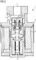
- FIG. 3 A piston slide valve 1 ′′ according to the invention is shown Fig. 3 shown position of the valve 1 "corresponds to that in Figure 2B shown position of the valve 1 '.
- the description Figure 2B referenced and the same reference numbers are used for corresponding parts.
- Piston slide valve 1 'shown has the in Fig. 3 shown inventive valve 1 "on a permanent magnet 14, which contributes to the in Fig. 3 to hold the maximum open position of the valve 1 "shown.
- the permanent magnet 14 is arranged between the first magnet armature 11 and the second magnet armature 12 in order to generate an attractive force between the first and second magnet armatures 11, 12 which corresponds to the force of the second biasing spring 10 counteracts.
- the magnetic attraction force generated by the permanent magnet 14 between the first and second magnet armatures 11, 12 is achieved energized state of the valve 1 "(compare Figure 2A ), in which the two magnet armatures 11, 12 are spaced apart and pressed apart by the second biasing spring 10, achieved no or only a very low attraction force between the first and second magnet armatures 11, 12 by the permanent magnet 14, since the attraction force increases with increasing Distance of Magnetic armature 11, 12 drops sharply.
- the characteristic curve of the second biasing spring 10 is essentially linear to the distance between the two magnet armatures 11, 12.
- the permanent magnet 14 is arranged in the first magnet armature 11.
- the permanent magnet 14 can be designed as a ring magnet which is inserted in a corresponding annular recess 15 on an end face 16 of the first magnet armature 11 (see also Fig. 4 ).
- the permanent magnet 14 can have any other shape and can be inserted or embedded in the magnet armature 11.
- the arrangement of the permanent magnet within the magnet armature 11 has several advantages. On the one hand, an iron circle closes over both magnet armatures 11, 12, so that the magnet 14 only increases the attractive force between the two magnet armatures 11, 12, but does not intervene in the electromagnetic circuit and, for example, also increases the attractive force to the pole part 17. This would disadvantageously require a stronger control spring 9 and thus a higher basic current to reach the maximum open position of the valve.
- the attraction force generated by the permanent magnet 14 between the first and second magnet armatures 11, 12 counteracts the force of the second biasing spring 10 and increases the holding force generated by the basic current supply between the first magnet armature 11 and the second magnet armature 12.
- the for holding the maximum open position of the valve 1 "necessary basic current can therefore be compared to a valve without the permanent magnet 14 (for example that in Figure 2A and 2 B shown valve 1 ') can be reduced.
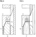
- FIG. 4 shown detail of the valve 1 " Fig. 3 A further measure can be seen which can improve the holding force between the first magnet armature 11 and the second magnet armature 12.
- the first magnet armature 11 has a flat step 18 on its end face 16, which points in the direction of the second magnet armature 12.
- the end face 16 of the first magnet armature has a slightly recessed area 19, which in particular can be a radially inner area. This means that there is only one outer edge direct contact between the first magnet armature 11 and the second magnet armature 12. In this way, the magnetic flux concentrates on a small contact area 20, so that the magnetic flux density increases there, which in turn generates an increased holding force between the two magnet armatures 11, 12.
- Fig. 5 shows approximately the course of the magnetic field lines around the permanent magnet 14 between the two magnet armatures 11, 12 when the coil is energized.
- the permanent magnet 14 is magnetized in the axial direction in order to improve the holding force between the first and second magnet armatures 11, 12 and to optimally counteract the force of the second biasing spring 10.
- the greatest magnetic flux density between the two magnet armatures is shown on the contact surface of the two magnet armatures (cf. Fig. 4 ).
Landscapes
- Engineering & Computer Science (AREA)
- General Engineering & Computer Science (AREA)
- Mechanical Engineering (AREA)
- Physics & Mathematics (AREA)
- Electromagnetism (AREA)
- Magnetically Actuated Valves (AREA)
- Power Engineering (AREA)
Claims (10)
- Vanne à tiroir-piston (1") actionnée électromagnétiquement, comprenant :- un boîtier de vanne (2) ayant un premier raccordement de fluide (3) et un deuxième raccordement de fluide (4) et au moins un passage de fluide (6) reliant les deux raccordements de fluide (3, 4), et- un agencement de tiroirs-pistons comportant un piston (5) qui, pour le réglage d'une surface libre de section transversale du passage de fluide (6), peut coulisser axialement dans le boîtier de vanne (2), une première armature d'aimant (11), reliée au piston (5), et une deuxième armature d'aimant (12), déplaçable axialement par rapport au piston (5), ainsi qu'un premier dispositif de précontrainte (9) et un deuxième dispositif de précontrainte (10),
cependant que le piston (5) est, par génération d'un champ électromagnétique par alimentation de la bobine (8) en courant, déplaçable axialement contre la force du premier dispositif de précontrainte (9), et cependant que le deuxième dispositif de précontrainte (10) s'appuie contre la première armature d'aimant (11) et la deuxième armature d'aimant (12), de telle sorte que le piston (5), à l'état de la bobine (8) non alimenté en courant, par déplacement axial en raison de la force du deuxième dispositif de précontrainte (10) contre la force du premier dispositif de précontrainte (9), adopte une position prédéterminée,
caractérisée en ce que la vanne à tiroir-piston (1") comprend en outre un aimant permanent (14) qui agit de telle façon sur au moins une de la première armature d'aimant (11) et de la deuxième armature d'aimant (12) qu'une force magnétique causée par l'aimant permanent (14) agit à l'encontre de la force du deuxième dispositif de précontrainte (10). - Vanne à tiroir-piston selon la revendication 1, cependant que l'aimant permanent (14) est agencé de telle façon que la force magnétique causée par l'aimant permanent (14) fait mouvoir l'une vers l'autre la première armature d'aimant (11) et la deuxième armature d'aimant (12).
- Vanne à tiroir-piston selon la revendication 1 ou 2, cependant que l'aimant permanent (14) est agencé de telle façon qu'il exerce une force d'attraction entre la première armature d'aimant (11) et la deuxième armature d'aimant (12).
- Vanne à tiroir-piston selon une des revendications de 1 à 3, cependant que l'aimant permanent (14) est agencé entre la première armature d'aimant (11) et la deuxième armature d'aimant (12).
- Vanne à tiroir-piston selon une des revendications de 1 à 4, cependant que l'aimant permanent (14) est agencé, en particulier encastré ou inséré, dans au moins une de la première armature d'aimant (11) et de la deuxième armature d'aimant (12), de préférence dans la première armature d'aimant (11).
- Vanne à tiroir-piston selon la revendication 5, cependant que l'aimant permanent (14) est agencé dans au moins une de la première armature d'aimant (11) et de la deuxième armature d'aimant (12) à proximité d'une surface tournée vers l'autre de la première et de la deuxième armature d'aimant (11, 12) correspondante.
- Vanne à tiroir-piston selon une des revendications de 1 à 6, cependant que l'aimant permanent (14) est aimanté dans le sens axial.
- Vanne à tiroir-piston selon une des revendications de 1 à 7, cependant que la force magnétique causée par l'aimant permanent (14) est plus faible que la force du deuxième dispositif de précontrainte (10).
- Vanne à tiroir-piston selon une des revendications de 1 à 8, cependant que l'aimant permanent (14) est un aimant annulaire.
- Amortisseur destiné à un véhicule, comprenant une vanne à tiroir-piston (1") selon une des revendications de 1 à 9.
Applications Claiming Priority (1)
| Application Number | Priority Date | Filing Date | Title |
|---|---|---|---|
| DE102017111726.1A DE102017111726A1 (de) | 2017-05-30 | 2017-05-30 | Kolbenschieberventil |
Publications (2)
| Publication Number | Publication Date |
|---|---|
| EP3409984A1 EP3409984A1 (fr) | 2018-12-05 |
| EP3409984B1 true EP3409984B1 (fr) | 2020-02-12 |
Family
ID=62455411
Family Applications (1)
| Application Number | Title | Priority Date | Filing Date |
|---|---|---|---|
| EP18174671.0A Active EP3409984B1 (fr) | 2017-05-30 | 2018-05-29 | Distributeur à tiroir cylindrique |
Country Status (3)
| Country | Link |
|---|---|
| US (1) | US10527120B2 (fr) |
| EP (1) | EP3409984B1 (fr) |
| DE (1) | DE102017111726A1 (fr) |
Families Citing this family (6)
| Publication number | Priority date | Publication date | Assignee | Title |
|---|---|---|---|---|
| DE102018107763A1 (de) * | 2018-04-03 | 2019-10-10 | Rausch & Pausch Gmbh | Magnetventil |
| KR20210009338A (ko) * | 2018-05-15 | 2021-01-26 | 백스터 인터내셔널 인코포레이티드 | 주사기 위치 안내 특징 및 폐색 검출을 갖는 주사기 펌프 |
| CN111692405A (zh) * | 2019-03-12 | 2020-09-22 | 林内株式会社 | 燃气电磁阀 |
| DE102020134522A1 (de) * | 2020-12-21 | 2022-06-23 | Kendrion (Villingen) Gmbh | Elektromagnet zur Erzeugung einer linearen Bewegung |
| DE102021134565A1 (de) | 2021-12-23 | 2023-06-29 | Eto Magnetic Gmbh | Regelventilvorrichtung zur Regelung von Dämpfungscharakteristiken und hydraulisches durchströmtes Magnetventil |
| EP4403810A1 (fr) * | 2023-01-19 | 2024-07-24 | Danfoss Scotland Limited | Ensemble soupape à commande électronique |
Citations (2)
| Publication number | Priority date | Publication date | Assignee | Title |
|---|---|---|---|---|
| US4546955A (en) * | 1982-10-14 | 1985-10-15 | Honeywell Inc. | Two-stage solenoid valve |
| EP3026310A1 (fr) * | 2014-11-28 | 2016-06-01 | Techspace Aero S.A. | Vanne électromagnétique pour gaz haute pression cryogénique |
Family Cites Families (11)
| Publication number | Priority date | Publication date | Assignee | Title |
|---|---|---|---|---|
| US4403765A (en) | 1979-11-23 | 1983-09-13 | John F. Taplin | Magnetic flux-shifting fluid valve |
| DE4033190C1 (fr) | 1990-10-19 | 1992-01-02 | Mercedes-Benz Aktiengesellschaft, 7000 Stuttgart, De | |
| DE4334350A1 (de) | 1993-10-08 | 1995-04-13 | Frank Pruefer | Elektromagnetisch betätigtes Ventil mit Permanentmagnet |
| US5996369A (en) | 1997-08-05 | 1999-12-07 | Tgk Co., Ltd. | Air conditioner with sub-condenser |
| US6609698B1 (en) * | 2000-10-25 | 2003-08-26 | Arichell Technologies, Inc. | Ferromagnetic/fluid valve actuator |
| EP1538366B1 (fr) | 2003-12-05 | 2006-02-08 | ThyssenKrupp Bilstein GmbH | Soupape de déviation pour amortisseur |
| US20070040135A1 (en) | 2005-02-09 | 2007-02-22 | Dave Dyer | Surface safety systems actuator operated by electro-magnetic device |
| DE102007057882B4 (de) | 2007-11-29 | 2014-03-06 | Hilite Germany Gmbh | Elektrohydraulisches Ventil |
| DE102008035899B4 (de) | 2008-07-31 | 2013-08-08 | Rausch & Pausch Gmbh | Kolbenschieberventil |
| DE102011078104A1 (de) | 2011-06-27 | 2012-12-27 | Rausch & Pausch Gmbh | Elektromagnetisch betätigtes Sitzventil |
| DE102013106214B4 (de) | 2013-06-14 | 2015-08-27 | Rausch & Pausch Gmbh | Kolbenschieberventil |
-
2017
- 2017-05-30 DE DE102017111726.1A patent/DE102017111726A1/de not_active Withdrawn
-
2018
- 2018-05-25 US US15/989,510 patent/US10527120B2/en active Active
- 2018-05-29 EP EP18174671.0A patent/EP3409984B1/fr active Active
Patent Citations (2)
| Publication number | Priority date | Publication date | Assignee | Title |
|---|---|---|---|---|
| US4546955A (en) * | 1982-10-14 | 1985-10-15 | Honeywell Inc. | Two-stage solenoid valve |
| EP3026310A1 (fr) * | 2014-11-28 | 2016-06-01 | Techspace Aero S.A. | Vanne électromagnétique pour gaz haute pression cryogénique |
Also Published As
| Publication number | Publication date |
|---|---|
| EP3409984A1 (fr) | 2018-12-05 |
| US10527120B2 (en) | 2020-01-07 |
| DE102017111726A1 (de) | 2018-12-06 |
| US20180347722A1 (en) | 2018-12-06 |
Similar Documents
| Publication | Publication Date | Title |
|---|---|---|
| EP3409984B1 (fr) | Distributeur à tiroir cylindrique | |
| EP2813737B1 (fr) | Soupape de robinet à piston | |
| EP2684200B1 (fr) | Actionneur électromagnétique | |
| DE102009049009B4 (de) | Aktuator für eine Verbrennungskraftmaschine | |
| EP3464968B1 (fr) | Dispositif soupape électromagnétique et système | |
| DE102007057882B4 (de) | Elektrohydraulisches Ventil | |
| DE102017214506A1 (de) | Proportionalventil zum Steuern eines gasförmigen Mediums | |
| EP1818951A1 (fr) | Electroaimant de levage | |
| EP2539614B1 (fr) | Valve hydraulique électromagnétique | |
| DE68913209T2 (de) | Elektrisch betätigbares ventil für kraftstoff-einspritzanlagen für brennkraftmaschinen. | |
| EP3364015B1 (fr) | Soupape de commutation électromagnétique et pompe haute pression à carburant | |
| EP3124840B1 (fr) | Soupape electrique | |
| EP2256333B1 (fr) | Soupape magnétique à fermeture active pour injecteurs magnétiques | |
| EP2813728B1 (fr) | Soupape de robinet à piston | |
| DE102014220877B3 (de) | Kraftstoffeinspritzventil | |
| DE602004007420T2 (de) | Elektromagnetischer Aktuator zur Betätigung eines Gaswechselventils an einer Kolbenbrennkraftmaschine und Brennkraftmaschine mit einem solchen Aktuator | |
| DE102013201756A1 (de) | Steuerventil mit zwei Magnetspulen | |
| DE102009032365A1 (de) | Elektromagnetantrieb für ein Ventil | |
| EP3364016B1 (fr) | Soupape de commutation électromagnétique et pompe haute pression à carburant | |
| DE102016203024A1 (de) | Elektromagnetisches Ventil mit Federzungen | |
| DE202016104309U1 (de) | Elektromagnetische Ventilvorrichtung und System | |
| DE102016107766A1 (de) | Elektromagnetventil sowie Betriebsverfahren | |
| DE102015226248A1 (de) | Elektromagnetisch betätigbares Einlassventil und Hochdruckpumpe mit Einlassventil | |
| WO1999039106A1 (fr) | Soupape hydraulique, notamment distributeur a siege hydraulique | |
| DE102008001823A1 (de) | Azimutal-Magnetaktor |
Legal Events
| Date | Code | Title | Description |
|---|---|---|---|
| PUAI | Public reference made under article 153(3) epc to a published international application that has entered the european phase |
Free format text: ORIGINAL CODE: 0009012 |
|
| STAA | Information on the status of an ep patent application or granted ep patent |
Free format text: STATUS: THE APPLICATION HAS BEEN PUBLISHED |
|
| AK | Designated contracting states |
Kind code of ref document: A1 Designated state(s): AL AT BE BG CH CY CZ DE DK EE ES FI FR GB GR HR HU IE IS IT LI LT LU LV MC MK MT NL NO PL PT RO RS SE SI SK SM TR |
|
| AX | Request for extension of the european patent |
Extension state: BA ME |
|
| STAA | Information on the status of an ep patent application or granted ep patent |
Free format text: STATUS: REQUEST FOR EXAMINATION WAS MADE |
|
| 17P | Request for examination filed |
Effective date: 20190508 |
|
| RBV | Designated contracting states (corrected) |
Designated state(s): AL AT BE BG CH CY CZ DE DK EE ES FI FR GB GR HR HU IE IS IT LI LT LU LV MC MK MT NL NO PL PT RO RS SE SI SK SM TR |
|
| GRAP | Despatch of communication of intention to grant a patent |
Free format text: ORIGINAL CODE: EPIDOSNIGR1 |
|
| STAA | Information on the status of an ep patent application or granted ep patent |
Free format text: STATUS: GRANT OF PATENT IS INTENDED |
|
| RAP1 | Party data changed (applicant data changed or rights of an application transferred) |
Owner name: RAUSCH & PAUSCH GMBH |
|
| INTG | Intention to grant announced |
Effective date: 20190916 |
|
| GRAS | Grant fee paid |
Free format text: ORIGINAL CODE: EPIDOSNIGR3 |
|
| GRAA | (expected) grant |
Free format text: ORIGINAL CODE: 0009210 |
|
| STAA | Information on the status of an ep patent application or granted ep patent |
Free format text: STATUS: THE PATENT HAS BEEN GRANTED |
|
| AK | Designated contracting states |
Kind code of ref document: B1 Designated state(s): AL AT BE BG CH CY CZ DE DK EE ES FI FR GB GR HR HU IE IS IT LI LT LU LV MC MK MT NL NO PL PT RO RS SE SI SK SM TR |
|
| REG | Reference to a national code |
Ref country code: GB Ref legal event code: FG4D Free format text: NOT ENGLISH |
|
| REG | Reference to a national code |
Ref country code: CH Ref legal event code: EP |
|
| REG | Reference to a national code |
Ref country code: AT Ref legal event code: REF Ref document number: 1232540 Country of ref document: AT Kind code of ref document: T Effective date: 20200215 |
|
| REG | Reference to a national code |
Ref country code: IE Ref legal event code: FG4D Free format text: LANGUAGE OF EP DOCUMENT: GERMAN |
|
| REG | Reference to a national code |
Ref country code: DE Ref legal event code: R096 Ref document number: 502018000750 Country of ref document: DE |
|
| REG | Reference to a national code |
Ref country code: DE Ref legal event code: R082 Ref document number: 502018000750 Country of ref document: DE Representative=s name: KLUNKER IP PATENTANWAELTE PARTG MBB, DE Ref country code: DE Ref legal event code: R081 Ref document number: 502018000750 Country of ref document: DE Owner name: RAPA AUTOMOTIVE GMBH & CO. KG, DE Free format text: FORMER OWNER: RAUSCH & PAUSCH GMBH, 95100 SELB, DE |
|
| RAP2 | Party data changed (patent owner data changed or rights of a patent transferred) |
Owner name: RAPA AUTOMOTIVE GMBH & CO. KG |
|
| PG25 | Lapsed in a contracting state [announced via postgrant information from national office to epo] |
Ref country code: RS Free format text: LAPSE BECAUSE OF FAILURE TO SUBMIT A TRANSLATION OF THE DESCRIPTION OR TO PAY THE FEE WITHIN THE PRESCRIBED TIME-LIMIT Effective date: 20200212 Ref country code: FI Free format text: LAPSE BECAUSE OF FAILURE TO SUBMIT A TRANSLATION OF THE DESCRIPTION OR TO PAY THE FEE WITHIN THE PRESCRIBED TIME-LIMIT Effective date: 20200212 Ref country code: NO Free format text: LAPSE BECAUSE OF FAILURE TO SUBMIT A TRANSLATION OF THE DESCRIPTION OR TO PAY THE FEE WITHIN THE PRESCRIBED TIME-LIMIT Effective date: 20200512 |
|
| REG | Reference to a national code |
Ref country code: LT Ref legal event code: MG4D |
|
| REG | Reference to a national code |
Ref country code: NL Ref legal event code: MP Effective date: 20200212 |
|
| PG25 | Lapsed in a contracting state [announced via postgrant information from national office to epo] |
Ref country code: HR Free format text: LAPSE BECAUSE OF FAILURE TO SUBMIT A TRANSLATION OF THE DESCRIPTION OR TO PAY THE FEE WITHIN THE PRESCRIBED TIME-LIMIT Effective date: 20200212 Ref country code: GR Free format text: LAPSE BECAUSE OF FAILURE TO SUBMIT A TRANSLATION OF THE DESCRIPTION OR TO PAY THE FEE WITHIN THE PRESCRIBED TIME-LIMIT Effective date: 20200513 Ref country code: SE Free format text: LAPSE BECAUSE OF FAILURE TO SUBMIT A TRANSLATION OF THE DESCRIPTION OR TO PAY THE FEE WITHIN THE PRESCRIBED TIME-LIMIT Effective date: 20200212 Ref country code: LV Free format text: LAPSE BECAUSE OF FAILURE TO SUBMIT A TRANSLATION OF THE DESCRIPTION OR TO PAY THE FEE WITHIN THE PRESCRIBED TIME-LIMIT Effective date: 20200212 Ref country code: IS Free format text: LAPSE BECAUSE OF FAILURE TO SUBMIT A TRANSLATION OF THE DESCRIPTION OR TO PAY THE FEE WITHIN THE PRESCRIBED TIME-LIMIT Effective date: 20200612 Ref country code: BG Free format text: LAPSE BECAUSE OF FAILURE TO SUBMIT A TRANSLATION OF THE DESCRIPTION OR TO PAY THE FEE WITHIN THE PRESCRIBED TIME-LIMIT Effective date: 20200512 |
|
| PG25 | Lapsed in a contracting state [announced via postgrant information from national office to epo] |
Ref country code: NL Free format text: LAPSE BECAUSE OF FAILURE TO SUBMIT A TRANSLATION OF THE DESCRIPTION OR TO PAY THE FEE WITHIN THE PRESCRIBED TIME-LIMIT Effective date: 20200212 |
|
| PG25 | Lapsed in a contracting state [announced via postgrant information from national office to epo] |
Ref country code: CZ Free format text: LAPSE BECAUSE OF FAILURE TO SUBMIT A TRANSLATION OF THE DESCRIPTION OR TO PAY THE FEE WITHIN THE PRESCRIBED TIME-LIMIT Effective date: 20200212 Ref country code: SK Free format text: LAPSE BECAUSE OF FAILURE TO SUBMIT A TRANSLATION OF THE DESCRIPTION OR TO PAY THE FEE WITHIN THE PRESCRIBED TIME-LIMIT Effective date: 20200212 Ref country code: RO Free format text: LAPSE BECAUSE OF FAILURE TO SUBMIT A TRANSLATION OF THE DESCRIPTION OR TO PAY THE FEE WITHIN THE PRESCRIBED TIME-LIMIT Effective date: 20200212 Ref country code: LT Free format text: LAPSE BECAUSE OF FAILURE TO SUBMIT A TRANSLATION OF THE DESCRIPTION OR TO PAY THE FEE WITHIN THE PRESCRIBED TIME-LIMIT Effective date: 20200212 Ref country code: PT Free format text: LAPSE BECAUSE OF FAILURE TO SUBMIT A TRANSLATION OF THE DESCRIPTION OR TO PAY THE FEE WITHIN THE PRESCRIBED TIME-LIMIT Effective date: 20200705 Ref country code: ES Free format text: LAPSE BECAUSE OF FAILURE TO SUBMIT A TRANSLATION OF THE DESCRIPTION OR TO PAY THE FEE WITHIN THE PRESCRIBED TIME-LIMIT Effective date: 20200212 Ref country code: EE Free format text: LAPSE BECAUSE OF FAILURE TO SUBMIT A TRANSLATION OF THE DESCRIPTION OR TO PAY THE FEE WITHIN THE PRESCRIBED TIME-LIMIT Effective date: 20200212 Ref country code: SM Free format text: LAPSE BECAUSE OF FAILURE TO SUBMIT A TRANSLATION OF THE DESCRIPTION OR TO PAY THE FEE WITHIN THE PRESCRIBED TIME-LIMIT Effective date: 20200212 Ref country code: DK Free format text: LAPSE BECAUSE OF FAILURE TO SUBMIT A TRANSLATION OF THE DESCRIPTION OR TO PAY THE FEE WITHIN THE PRESCRIBED TIME-LIMIT Effective date: 20200212 |
|
| REG | Reference to a national code |
Ref country code: DE Ref legal event code: R097 Ref document number: 502018000750 Country of ref document: DE |
|
| PLBE | No opposition filed within time limit |
Free format text: ORIGINAL CODE: 0009261 |
|
| STAA | Information on the status of an ep patent application or granted ep patent |
Free format text: STATUS: NO OPPOSITION FILED WITHIN TIME LIMIT |
|
| 26N | No opposition filed |
Effective date: 20201113 |
|
| PG25 | Lapsed in a contracting state [announced via postgrant information from national office to epo] |
Ref country code: MC Free format text: LAPSE BECAUSE OF FAILURE TO SUBMIT A TRANSLATION OF THE DESCRIPTION OR TO PAY THE FEE WITHIN THE PRESCRIBED TIME-LIMIT Effective date: 20200212 Ref country code: IT Free format text: LAPSE BECAUSE OF FAILURE TO SUBMIT A TRANSLATION OF THE DESCRIPTION OR TO PAY THE FEE WITHIN THE PRESCRIBED TIME-LIMIT Effective date: 20200212 |
|
| PG25 | Lapsed in a contracting state [announced via postgrant information from national office to epo] |
Ref country code: SI Free format text: LAPSE BECAUSE OF FAILURE TO SUBMIT A TRANSLATION OF THE DESCRIPTION OR TO PAY THE FEE WITHIN THE PRESCRIBED TIME-LIMIT Effective date: 20200212 Ref country code: PL Free format text: LAPSE BECAUSE OF FAILURE TO SUBMIT A TRANSLATION OF THE DESCRIPTION OR TO PAY THE FEE WITHIN THE PRESCRIBED TIME-LIMIT Effective date: 20200212 |
|
| REG | Reference to a national code |
Ref country code: BE Ref legal event code: MM Effective date: 20200531 |
|
| PG25 | Lapsed in a contracting state [announced via postgrant information from national office to epo] |
Ref country code: LU Free format text: LAPSE BECAUSE OF NON-PAYMENT OF DUE FEES Effective date: 20200529 |
|
| PG25 | Lapsed in a contracting state [announced via postgrant information from national office to epo] |
Ref country code: FR Free format text: LAPSE BECAUSE OF NON-PAYMENT OF DUE FEES Effective date: 20200531 Ref country code: IE Free format text: LAPSE BECAUSE OF NON-PAYMENT OF DUE FEES Effective date: 20200529 |
|
| PG25 | Lapsed in a contracting state [announced via postgrant information from national office to epo] |
Ref country code: BE Free format text: LAPSE BECAUSE OF NON-PAYMENT OF DUE FEES Effective date: 20200531 |
|
| REG | Reference to a national code |
Ref country code: CH Ref legal event code: PL |
|
| PG25 | Lapsed in a contracting state [announced via postgrant information from national office to epo] |
Ref country code: CH Free format text: LAPSE BECAUSE OF NON-PAYMENT OF DUE FEES Effective date: 20210531 Ref country code: LI Free format text: LAPSE BECAUSE OF NON-PAYMENT OF DUE FEES Effective date: 20210531 |
|
| PG25 | Lapsed in a contracting state [announced via postgrant information from national office to epo] |
Ref country code: TR Free format text: LAPSE BECAUSE OF FAILURE TO SUBMIT A TRANSLATION OF THE DESCRIPTION OR TO PAY THE FEE WITHIN THE PRESCRIBED TIME-LIMIT Effective date: 20200212 Ref country code: MT Free format text: LAPSE BECAUSE OF FAILURE TO SUBMIT A TRANSLATION OF THE DESCRIPTION OR TO PAY THE FEE WITHIN THE PRESCRIBED TIME-LIMIT Effective date: 20200212 Ref country code: CY Free format text: LAPSE BECAUSE OF FAILURE TO SUBMIT A TRANSLATION OF THE DESCRIPTION OR TO PAY THE FEE WITHIN THE PRESCRIBED TIME-LIMIT Effective date: 20200212 |
|
| PG25 | Lapsed in a contracting state [announced via postgrant information from national office to epo] |
Ref country code: MK Free format text: LAPSE BECAUSE OF FAILURE TO SUBMIT A TRANSLATION OF THE DESCRIPTION OR TO PAY THE FEE WITHIN THE PRESCRIBED TIME-LIMIT Effective date: 20200212 Ref country code: AL Free format text: LAPSE BECAUSE OF FAILURE TO SUBMIT A TRANSLATION OF THE DESCRIPTION OR TO PAY THE FEE WITHIN THE PRESCRIBED TIME-LIMIT Effective date: 20200212 |
|
| GBPC | Gb: european patent ceased through non-payment of renewal fee |
Effective date: 20220529 |
|
| PG25 | Lapsed in a contracting state [announced via postgrant information from national office to epo] |
Ref country code: GB Free format text: LAPSE BECAUSE OF NON-PAYMENT OF DUE FEES Effective date: 20220529 |
|
| P01 | Opt-out of the competence of the unified patent court (upc) registered |
Effective date: 20230522 |
|
| PGFP | Annual fee paid to national office [announced via postgrant information from national office to epo] |
Ref country code: DE Payment date: 20230726 Year of fee payment: 6 |
|
| REG | Reference to a national code |
Ref country code: AT Ref legal event code: MM01 Ref document number: 1232540 Country of ref document: AT Kind code of ref document: T Effective date: 20230529 |
|
| PG25 | Lapsed in a contracting state [announced via postgrant information from national office to epo] |
Ref country code: AT Free format text: LAPSE BECAUSE OF NON-PAYMENT OF DUE FEES Effective date: 20230529 |
|
| PG25 | Lapsed in a contracting state [announced via postgrant information from national office to epo] |
Ref country code: AT Free format text: LAPSE BECAUSE OF NON-PAYMENT OF DUE FEES Effective date: 20230529 |