EP3409935B1 - Section de turbine de turboréacteur à double flux à taux de dilution élevé - Google Patents
Section de turbine de turboréacteur à double flux à taux de dilution élevé Download PDFInfo
- Publication number
- EP3409935B1 EP3409935B1 EP18184558.7A EP18184558A EP3409935B1 EP 3409935 B1 EP3409935 B1 EP 3409935B1 EP 18184558 A EP18184558 A EP 18184558A EP 3409935 B1 EP3409935 B1 EP 3409935B1
- Authority
- EP
- European Patent Office
- Prior art keywords
- low pressure
- engine
- pressure turbine
- fan
- turbine section
- Prior art date
- Legal status (The legal status is an assumption and is not a legal conclusion. Google has not performed a legal analysis and makes no representation as to the accuracy of the status listed.)
- Active
Links
- 230000005540 biological transmission Effects 0.000 claims description 15
- 230000009467 reduction Effects 0.000 claims description 15
- 230000007246 mechanism Effects 0.000 claims description 9
- 230000008878 coupling Effects 0.000 claims description 2
- 238000010168 coupling process Methods 0.000 claims description 2
- 238000005859 coupling reaction Methods 0.000 claims description 2
- 239000012530 fluid Substances 0.000 claims 3
- 239000000463 material Substances 0.000 description 6
- 230000008901 benefit Effects 0.000 description 2
- 230000008859 change Effects 0.000 description 2
- 239000000446 fuel Substances 0.000 description 2
- 239000002184 metal Substances 0.000 description 2
- 238000004806 packaging method and process Methods 0.000 description 2
- 238000007789 sealing Methods 0.000 description 2
- 239000002131 composite material Substances 0.000 description 1
- 238000001816 cooling Methods 0.000 description 1
- 230000005611 electricity Effects 0.000 description 1
- 238000005516 engineering process Methods 0.000 description 1
- 238000004519 manufacturing process Methods 0.000 description 1
- 238000005259 measurement Methods 0.000 description 1
- 239000012255 powdered metal Substances 0.000 description 1
- 125000006850 spacer group Chemical group 0.000 description 1
Images


Classifications
-
- F—MECHANICAL ENGINEERING; LIGHTING; HEATING; WEAPONS; BLASTING
- F02—COMBUSTION ENGINES; HOT-GAS OR COMBUSTION-PRODUCT ENGINE PLANTS
- F02C—GAS-TURBINE PLANTS; AIR INTAKES FOR JET-PROPULSION PLANTS; CONTROLLING FUEL SUPPLY IN AIR-BREATHING JET-PROPULSION PLANTS
- F02C9/00—Controlling gas-turbine plants; Controlling fuel supply in air- breathing jet-propulsion plants
- F02C9/16—Control of working fluid flow
- F02C9/18—Control of working fluid flow by bleeding, bypassing or acting on variable working fluid interconnections between turbines or compressors or their stages
-
- F—MECHANICAL ENGINEERING; LIGHTING; HEATING; WEAPONS; BLASTING
- F01—MACHINES OR ENGINES IN GENERAL; ENGINE PLANTS IN GENERAL; STEAM ENGINES
- F01D—NON-POSITIVE DISPLACEMENT MACHINES OR ENGINES, e.g. STEAM TURBINES
- F01D1/00—Non-positive-displacement machines or engines, e.g. steam turbines
- F01D1/02—Non-positive-displacement machines or engines, e.g. steam turbines with stationary working-fluid guiding means and bladed or like rotor, e.g. multi-bladed impulse steam turbines
-
- F—MECHANICAL ENGINEERING; LIGHTING; HEATING; WEAPONS; BLASTING
- F01—MACHINES OR ENGINES IN GENERAL; ENGINE PLANTS IN GENERAL; STEAM ENGINES
- F01D—NON-POSITIVE DISPLACEMENT MACHINES OR ENGINES, e.g. STEAM TURBINES
- F01D25/00—Component parts, details, or accessories, not provided for in, or of interest apart from, other groups
- F01D25/24—Casings; Casing parts, e.g. diaphragms, casing fastenings
-
- F—MECHANICAL ENGINEERING; LIGHTING; HEATING; WEAPONS; BLASTING
- F01—MACHINES OR ENGINES IN GENERAL; ENGINE PLANTS IN GENERAL; STEAM ENGINES
- F01D—NON-POSITIVE DISPLACEMENT MACHINES OR ENGINES, e.g. STEAM TURBINES
- F01D5/00—Blades; Blade-carrying members; Heating, heat-insulating, cooling or antivibration means on the blades or the members
- F01D5/02—Blade-carrying members, e.g. rotors
-
- F—MECHANICAL ENGINEERING; LIGHTING; HEATING; WEAPONS; BLASTING
- F01—MACHINES OR ENGINES IN GENERAL; ENGINE PLANTS IN GENERAL; STEAM ENGINES
- F01D—NON-POSITIVE DISPLACEMENT MACHINES OR ENGINES, e.g. STEAM TURBINES
- F01D9/00—Stators
- F01D9/02—Nozzles; Nozzle boxes; Stator blades; Guide conduits, e.g. individual nozzles
- F01D9/04—Nozzles; Nozzle boxes; Stator blades; Guide conduits, e.g. individual nozzles forming ring or sector
- F01D9/041—Nozzles; Nozzle boxes; Stator blades; Guide conduits, e.g. individual nozzles forming ring or sector using blades
-
- F—MECHANICAL ENGINEERING; LIGHTING; HEATING; WEAPONS; BLASTING
- F02—COMBUSTION ENGINES; HOT-GAS OR COMBUSTION-PRODUCT ENGINE PLANTS
- F02C—GAS-TURBINE PLANTS; AIR INTAKES FOR JET-PROPULSION PLANTS; CONTROLLING FUEL SUPPLY IN AIR-BREATHING JET-PROPULSION PLANTS
- F02C3/00—Gas-turbine plants characterised by the use of combustion products as the working fluid
- F02C3/04—Gas-turbine plants characterised by the use of combustion products as the working fluid having a turbine driving a compressor
- F02C3/107—Gas-turbine plants characterised by the use of combustion products as the working fluid having a turbine driving a compressor with two or more rotors connected by power transmission
- F02C3/113—Gas-turbine plants characterised by the use of combustion products as the working fluid having a turbine driving a compressor with two or more rotors connected by power transmission with variable power transmission between rotors
-
- F—MECHANICAL ENGINEERING; LIGHTING; HEATING; WEAPONS; BLASTING
- F02—COMBUSTION ENGINES; HOT-GAS OR COMBUSTION-PRODUCT ENGINE PLANTS
- F02C—GAS-TURBINE PLANTS; AIR INTAKES FOR JET-PROPULSION PLANTS; CONTROLLING FUEL SUPPLY IN AIR-BREATHING JET-PROPULSION PLANTS
- F02C7/00—Features, components parts, details or accessories, not provided for in, or of interest apart form groups F02C1/00 - F02C6/00; Air intakes for jet-propulsion plants
- F02C7/20—Mounting or supporting of plant; Accommodating heat expansion or creep
-
- F—MECHANICAL ENGINEERING; LIGHTING; HEATING; WEAPONS; BLASTING
- F02—COMBUSTION ENGINES; HOT-GAS OR COMBUSTION-PRODUCT ENGINE PLANTS
- F02C—GAS-TURBINE PLANTS; AIR INTAKES FOR JET-PROPULSION PLANTS; CONTROLLING FUEL SUPPLY IN AIR-BREATHING JET-PROPULSION PLANTS
- F02C7/00—Features, components parts, details or accessories, not provided for in, or of interest apart form groups F02C1/00 - F02C6/00; Air intakes for jet-propulsion plants
- F02C7/36—Power transmission arrangements between the different shafts of the gas turbine plant, or between the gas-turbine plant and the power user
-
- F—MECHANICAL ENGINEERING; LIGHTING; HEATING; WEAPONS; BLASTING
- F02—COMBUSTION ENGINES; HOT-GAS OR COMBUSTION-PRODUCT ENGINE PLANTS
- F02K—JET-PROPULSION PLANTS
- F02K3/00—Plants including a gas turbine driving a compressor or a ducted fan
- F02K3/02—Plants including a gas turbine driving a compressor or a ducted fan in which part of the working fluid by-passes the turbine and combustion chamber
- F02K3/025—Plants including a gas turbine driving a compressor or a ducted fan in which part of the working fluid by-passes the turbine and combustion chamber the by-pass flow being at least partly used to create an independent thrust component
-
- F—MECHANICAL ENGINEERING; LIGHTING; HEATING; WEAPONS; BLASTING
- F02—COMBUSTION ENGINES; HOT-GAS OR COMBUSTION-PRODUCT ENGINE PLANTS
- F02K—JET-PROPULSION PLANTS
- F02K3/00—Plants including a gas turbine driving a compressor or a ducted fan
- F02K3/02—Plants including a gas turbine driving a compressor or a ducted fan in which part of the working fluid by-passes the turbine and combustion chamber
- F02K3/04—Plants including a gas turbine driving a compressor or a ducted fan in which part of the working fluid by-passes the turbine and combustion chamber the plant including ducted fans, i.e. fans with high volume, low pressure outputs, for augmenting the jet thrust, e.g. of double-flow type
- F02K3/06—Plants including a gas turbine driving a compressor or a ducted fan in which part of the working fluid by-passes the turbine and combustion chamber the plant including ducted fans, i.e. fans with high volume, low pressure outputs, for augmenting the jet thrust, e.g. of double-flow type with front fan
-
- F—MECHANICAL ENGINEERING; LIGHTING; HEATING; WEAPONS; BLASTING
- F02—COMBUSTION ENGINES; HOT-GAS OR COMBUSTION-PRODUCT ENGINE PLANTS
- F02K—JET-PROPULSION PLANTS
- F02K3/00—Plants including a gas turbine driving a compressor or a ducted fan
- F02K3/02—Plants including a gas turbine driving a compressor or a ducted fan in which part of the working fluid by-passes the turbine and combustion chamber
- F02K3/04—Plants including a gas turbine driving a compressor or a ducted fan in which part of the working fluid by-passes the turbine and combustion chamber the plant including ducted fans, i.e. fans with high volume, low pressure outputs, for augmenting the jet thrust, e.g. of double-flow type
- F02K3/075—Plants including a gas turbine driving a compressor or a ducted fan in which part of the working fluid by-passes the turbine and combustion chamber the plant including ducted fans, i.e. fans with high volume, low pressure outputs, for augmenting the jet thrust, e.g. of double-flow type controlling flow ratio between flows
-
- F—MECHANICAL ENGINEERING; LIGHTING; HEATING; WEAPONS; BLASTING
- F02—COMBUSTION ENGINES; HOT-GAS OR COMBUSTION-PRODUCT ENGINE PLANTS
- F02K—JET-PROPULSION PLANTS
- F02K7/00—Plants in which the working fluid is used in a jet only, i.e. the plants not having a turbine or other engine driving a compressor or a ducted fan; Control thereof
- F02K7/02—Plants in which the working fluid is used in a jet only, i.e. the plants not having a turbine or other engine driving a compressor or a ducted fan; Control thereof the jet being intermittent, i.e. pulse-jet
- F02K7/06—Plants in which the working fluid is used in a jet only, i.e. the plants not having a turbine or other engine driving a compressor or a ducted fan; Control thereof the jet being intermittent, i.e. pulse-jet with combustion chambers having valves
-
- F—MECHANICAL ENGINEERING; LIGHTING; HEATING; WEAPONS; BLASTING
- F05—INDEXING SCHEMES RELATING TO ENGINES OR PUMPS IN VARIOUS SUBCLASSES OF CLASSES F01-F04
- F05D—INDEXING SCHEME FOR ASPECTS RELATING TO NON-POSITIVE-DISPLACEMENT MACHINES OR ENGINES, GAS-TURBINES OR JET-PROPULSION PLANTS
- F05D2220/00—Application
- F05D2220/30—Application in turbines
- F05D2220/32—Application in turbines in gas turbines
-
- F—MECHANICAL ENGINEERING; LIGHTING; HEATING; WEAPONS; BLASTING
- F05—INDEXING SCHEMES RELATING TO ENGINES OR PUMPS IN VARIOUS SUBCLASSES OF CLASSES F01-F04
- F05D—INDEXING SCHEME FOR ASPECTS RELATING TO NON-POSITIVE-DISPLACEMENT MACHINES OR ENGINES, GAS-TURBINES OR JET-PROPULSION PLANTS
- F05D2260/00—Function
- F05D2260/40—Transmission of power
- F05D2260/403—Transmission of power through the shape of the drive components
- F05D2260/4031—Transmission of power through the shape of the drive components as in toothed gearing
- F05D2260/40311—Transmission of power through the shape of the drive components as in toothed gearing of the epicyclical, planetary or differential type
-
- F—MECHANICAL ENGINEERING; LIGHTING; HEATING; WEAPONS; BLASTING
- F05—INDEXING SCHEMES RELATING TO ENGINES OR PUMPS IN VARIOUS SUBCLASSES OF CLASSES F01-F04
- F05D—INDEXING SCHEME FOR ASPECTS RELATING TO NON-POSITIVE-DISPLACEMENT MACHINES OR ENGINES, GAS-TURBINES OR JET-PROPULSION PLANTS
- F05D2260/00—Function
- F05D2260/60—Fluid transfer
- F05D2260/606—Bypassing the fluid
-
- Y—GENERAL TAGGING OF NEW TECHNOLOGICAL DEVELOPMENTS; GENERAL TAGGING OF CROSS-SECTIONAL TECHNOLOGIES SPANNING OVER SEVERAL SECTIONS OF THE IPC; TECHNICAL SUBJECTS COVERED BY FORMER USPC CROSS-REFERENCE ART COLLECTIONS [XRACs] AND DIGESTS
- Y02—TECHNOLOGIES OR APPLICATIONS FOR MITIGATION OR ADAPTATION AGAINST CLIMATE CHANGE
- Y02T—CLIMATE CHANGE MITIGATION TECHNOLOGIES RELATED TO TRANSPORTATION
- Y02T50/00—Aeronautics or air transport
- Y02T50/60—Efficient propulsion technologies, e.g. for aircraft
Definitions
- the disclosure relates to turbofan engines. More particularly, the disclosure relates to low pressure turbine sections of turbofan engines which power the fans via a speed reduction mechanism.
- turbofan engine as set forth in claim 1.
- a fan case may encircle the fan blades radially outboard of the engine case.
- the compressor may comprise a low pressure compressor section and a high pressure compressor section.
- the blades of the low pressure compressor section and low pressure turbine section may share a low shaft.
- the high pressure compressor section and a high pressure turbine section of the turbine may share a high shaft.
- the speed reduction mechanism may comprise an epicyclic transmission coupling the low speed shaft to a fan shaft to drive the fan with a speed reduction.
- the low pressure turbine section may have an exemplary 2 to 6 blade stages or 2 to 3 blade stages.
- a ratio of maximum gaspath radius along the low pressure turbine section to maximum radius of the fan may be less than 0.55, or less than 0.50, or between 0.35 and 0.50.
- said ratio of low pressure turbine section airfoil count to bypass area ratio may be between is 10 and 150.
- an airfoil count of the low pressure turbine section may be below 1700, for example below 1600.
- the engine may be in combination with a mounting arrangement (e.g., of an engine pylon) wherein an aft mount reacts at least a thrust load.
- a mounting arrangement e.g., of an engine pylon
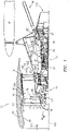
- FIG. 1 shows a turbofan engine 20 having a main housing (engine case) 22 containing a rotor shaft assembly 23.
- An exemplary engine is a high-bypass turbofan.
- the normal cruise condition bypass area ratio of air mass flowing outside the case 22 (e.g., the compressor sections and combustor) to air mass passing through the case 22 is typically in excess of about 4.0 and, more narrowly, typically between about 4.0 and about 12.0.
- a high pressure turbine section (gas generating turbine) 26 and a low pressure turbine section 27 respectively drive a high pressure compressor section 28 and a low pressure compressor section 30.
- the high pressure turbine section experiences higher pressures that the low pressure turbine section.
- a low pressure turbine section is a section that powers a fan 42.
- a two-spool (plus fan) engine is shown, one of many alternative variations involves a three-spool (plus fan) engine wherein an intermediate spool comprises an intermediate pressure compressor between the low fan and high pressure compressor section and an intermediate pressure turbine between the high pressure turbine section and low pressure turbine section.
- the engine extends along a longitudinal axis 500 from a fore end to an aft end. Adjacent the fore end, a shroud (fan case) 40 encircles the fan 42 and is supported by vanes 44. An aerodynamic nacelle around the fan case is shown and an aerodynamic nacelle 45 around the engine case is shown.
- a shroud (fan case) 40 Adjacent the fore end, a shroud (fan case) 40 encircles the fan 42 and is supported by vanes 44.
- An aerodynamic nacelle around the fan case is shown and an aerodynamic nacelle 45 around the engine case is shown.
- the low shaft portion 25 of the rotor shaft assembly 23 drives the fan 42 through a speed reduction mechanism 46.
- An exemplary speed reduction mechanism is an epicyclic transmission, namely a star or planetary gear system.
- an inlet airflow 520 entering the nacelle is divided into a portion 522 passing along a core flowpath 524 and a bypass portion 526 passing along a bypass flowpath 528.
- flow along the core flowpath sequentially passes through the low pressure compressor section, high pressure compressor section, a combustor 48, the high pressure turbine section, and the low pressure turbine section before exiting from an outlet 530.
- FIG. 3 schematically shows details of the transmission 46.
- a forward end of the low shaft 25 is coupled to a sun gear 52 (or other high speed input to the speed reduction mechanism).
- the externally-toothed sun gear 52 is encircled by a number of externally-toothed star gears 56 and an internally-toothed ring gear 54.
- the exemplary ring gear is coupled to the fan to rotate with the fan as a unit.
- the star gears 56 are positioned between and enmeshed with the sun gear and ring gear.
- a cage or star carrier assembly 60 carries the star gears via associated journals 62.
- the exemplary star carrier is substantially irrotatably mounted relative via fingers 404 to the case 22.
- Another transmission/gearbox combination has the star carrier connected to the fan and the ring is fixed to the fixed structure (case) is possible and such is commonly referred to as a planetary gearbox.
- the speed reduction ratio is determined by the ratio of diameters within the gearbox.
- An exemplary reduction is between about 2:1 and about 13:1.
- the exemplary fan ( FIG. 1 ) comprises a circumferential array of blades 70.
- Each blade comprises an airfoil 72 having a leading edge 74 and a trailing edge 76 and extending from an inboard end 78 at a platform to an outboard end 80 (i.e., a free tip).
- the outboard end 80 is in close facing proximity to a rub strip 82 along an interior surface 84 of the nacelle and fan case.
- a pylon 94 is mounted to the fan case and/or to the other engine cases.
- the exemplary pylon 94 may be as disclosed in US Patent Application Ser. No. 11/832,107 ( US2009/0056343A1 ).
- the pylon comprises a forward mount 100 and an aft/rear mount 102.
- the forward mount may engage the engine intermediate case (IMC) and the aft mount may engage the engine thrust case.
- the aft mount reacts at least a thrust load of the engine.
- FIG. 2 shows the low pressure turbine section 27 as comprising an exemplary three blade stages 200, 202, 204.
- An exemplary blade stage count is 2-6, more narrowly, 2-4, or 2-3, 3-5, or 3-4. Interspersed between the blade stages are vane stages 206 and 208.
- Each exemplary blade stage comprises a disk 210, 212, and 214, respectively.
- a circumferential array of blades extends from peripheries of each of the disks.
- Each exemplary blade comprises an airfoil 220 extending from an inner diameter (ID) platform 222 to an outer diameter (OD) shroud 224 (shown integral with the airfoil).
- An alternative may be an unshrouded blade with a rotational gap between the tip of the blade and a stationary blade outer air seal (BOAS).
- BOAS stationary blade outer air seal
- Each exemplary shroud 224 has outboard sealing ridges which seal with abradable seals (e.g., honeycomb) fixed to the case.
- the exemplary vanes in stages 206 and 208 include airfoils 230 extending from ID platforms 232 to OD shrouds 234.
- the exemplary OD shrouds 234 are directly mounted to the case.
- the exemplary platforms 232 carry seals for sealing with inter-disk knife edges protruding outwardly from inter-disk spacers which may be separate from the adjacent disks or unitarily formed with one of the adjacent disks.
- Each exemplary disk 210, 212, 214 comprises an enlarged central annular protuberance or "bore" 240, 242, 244 and a thinner radial web 246, 248, 250 extending radially outboard from the bore.
- the bore imparts structural strength allowing the disk to withstand centrifugal loading which the disk would otherwise be unable to withstand.
- a turbofan engine is characterized by its bypass ratio (mass flow ratio of air bypassing the core to air passing through the core) and the geometric bypass area ratio (ratio of fan duct annulus area outside/outboard of the low pressure compressor section inlet (i.e., at location 260 in FIG. 1 ) to low pressure compressor section inlet annulus area (i.e., at location 262 in FIG. 2 ).
- High bypass engines typically have bypass area ratio of at least four. There has been a correlation between increased bypass area ratio and increased low pressure turbine section radius and low pressure turbine section airfoil count. As is discussed below, this correlation may be broken by having an engine with relatively high bypass area ratio and relatively low turbine size.
- a speed reduction mechanism e.g., a transmission
- a speed reduction mechanism e.g., a transmission
- the low pressure turbine section By employing a speed reduction mechanism (e.g., a transmission) to allow the low pressure turbine section to turn very fast relative to the fan and by employing low pressure turbine section design features for high speed, it is possible to create a compact turbine module (e.g., while producing the same amount of thrust and increasing bypass area ratio).
- the exemplary transmission is a epicyclic transmission.
- Alternative transmissions include composite belt transmissions, metal chain belt transmissions, fluidic transmissions, and electric means (e.g., a motor/generator set where the turbine turns a generator providing electricity to an electric motor which drives the fan) .
- the core gaspath extends from an inboard boundary (e.g., at blade hubs or outboard surfaces of platforms of associated blades and vanes) to an outboard boundary (e.g., at blade tips and inboard surfaces of blade outer air seals for unshrouded blade tips and at inboard surfaces of OD shrouds of shrouded blade tips and at inboard surfaces of OD shrouds of the vanes).
- inboard boundary e.g., at blade hubs or outboard surfaces of platforms of associated blades and vanes
- an outboard boundary e.g., at blade tips and inboard surfaces of blade outer air seals for unshrouded blade tips and at inboard surfaces of OD shrouds of shrouded blade tips and at inboard surfaces of OD shrouds of the vanes.
- R O -R I radial span
- R I radius
- R I radius
- An exemplary fan size measurement is the maximum tip radius R Tmax . of the fan blades.
- An exemplary ratio is the maximum R O along the low pressure turbine section to R Tmax . of the fan blades. Exemplary values for this ratio are less than (about) 0.55 (e.g., (about) 0.35-55), more narrowly, less than (about) 0.50, or (about) 0.35-0.50.
- the designer may balance multiple physical phenomena to arrive at a system solution as defined by the low pressure turbine hub-to-tip ratio, the fan maximum tip radius to low pressure turbine maximum R O ratio, the bypass area ratio, and the bypass area ratio to low pressure turbine airfoil count ratio.
- These concerns include, but are not limited to: a) aerodynamics within the low pressure turbine, b) low pressure turbine blade structural design, c) low pressure turbine disk structural design, and d) the shaft connecting the low pressure turbine to the low pressure compressor and speed reduction device between the low pressure compressor and fan.
- the designer can choose to make low pressure turbine section disk bores much thicker relative to prior art turbine bores and the bores may be at a much smaller radius R B . This increases the amount of mass at less than a "self sustaining radius”.
- Another means is to choose disk materials of greater strength than prior art such as the use of wrought powdered metal disks to allow for extremely high centrifugal blade pulls associated with the compactness.
- AN 2 is the annulus area of the exit of the low pressure turbine divided by the low pressure turbine rpm squared at its redline or maximum speed.
- AN 2 is the annulus area of the exit of the low pressure turbine divided by the low pressure turbine rpm squared at its redline or maximum speed.
- low pressure turbine section size Another characteristic of low pressure turbine section size is airfoil count (numerical count of all of the blades and vanes in the low pressure turbine). Airfoil metal angles can be selected such that airfoil count is low or extremely low relative to a direct drive turbine. In known prior art engines having bypass area ratio above 6.0 (e.g. 8.0-20), low pressure turbine sections involve ratios of airfoil count to bypass area ratio above 190.
- the ratio of airfoil count to bypass area ratio may be below (about) 170 to as low as 10. (e.g., below (about) 150 or an exemplary (about) 10-170, more narrowly (about) 10-150). Further, in such embodiments the airfoil count may be below (about) 1700, or below (about) 1600.
Landscapes
- Engineering & Computer Science (AREA)
- Chemical & Material Sciences (AREA)
- Combustion & Propulsion (AREA)
- Mechanical Engineering (AREA)
- General Engineering & Computer Science (AREA)
- Physics & Mathematics (AREA)
- Fluid Mechanics (AREA)
- Structures Of Non-Positive Displacement Pumps (AREA)
- Turbine Rotor Nozzle Sealing (AREA)
Claims (14)
- Moteur à turboréacteur à double flux (20) comprenant :un carter de moteur (22) ;un trajet de gaz à travers le carter de moteur (22) ;un ventilateur (42) ayant un réseau circonférentiel de pales de ventilateur (70) ;un compresseur en communication fluidique avec le ventilateur (42) ;une chambre de combustion en communication fluidique avec le compresseur ;une turbine en communication fluidique avec la chambre de combustion, la turbine ayant une section de turbine basse pression (27) ; etun mécanisme de réduction de vitesse (46) couplant la section de turbine basse pression (27) au ventilateur (42) ; dans lequel :un rapport de zone de dérivation va de 8,0 à 20,0 ;un rapport d'un nombre de profil aérodynamique de section de turbine basse pression au rapport de zone de dérivation est inférieur à environ 170 ; etun rapport moyeu-pointe RI:RO) de la section de turbine basse pression (27) se situe entre environ 0,42 et environ 0,48 mesuré à l'emplacement axial RO maximal dans la section de turbine basse pression (27).
- Moteur selon la revendication 1, comprenant en outre :
un carter de ventilateur (40) encerclant les pales de ventilateur (70) radialement à l'extérieur du carter de moteur (22) . - Moteur selon une quelconque revendication précédente, dans lequel :
la section de turbine basse pression a 2 à 6 étages de pales, par exemple 2 à 3 étages de pales. - Moteur selon une quelconque revendication précédente dans lequel :
un rapport d'un rayon maximum de trajet de gaz le long de la section de turbine basse pression (27) au rayon maximum du ventilateur (14) est inférieur à environ 0,55. - Moteur selon la revendication 4 dans lequel :
ledit rapport d'un rayon maximum de trajet de gaz le long de la section de turbine basse pression (17) au rayon maximum du ventilateur (14) est inférieur à environ 0,50. - Moteur selon la revendication 4 dans lequel :
ledit rapport d'un rayon maximum de trajet de gaz le long de la section de turbine basse pression (17) au rayon maximum du ventilateur (42) est compris entre environ 0,35 et environ 0,50. - Moteur selon une quelconque revendication précédente dans lequel :
un rapport d'un nombre de surfaces portantes de section de turbine basse pression au rapport de zone de dérivation est compris entre environ 10 et environ 150. - Moteur selon une quelconque revendication précédente dans lequel :
un nombre de surfaces portantes de la section de turbine basse pression (17) est en dessous d'environ 1 600. - Moteur selon la revendication 1 dans lequel :
le compresseur comprend :une section de compresseur basse pression (30) ; etune section de compresseur haute pression (28). - Moteur selon la revendication 9 dans lequel :
la turbine a une section de turbine haute pression (26) couplée pour entraîner la section de compresseur haute pression (28). - Moteur selon la revendication 10, dans lequel :
il n'existe pas de sections de compresseur ou de turbine supplémentaires. - Moteur selon l'une quelconque des revendications 9, 10 ou 11 dans lequel :des pales de la section de compresseur basse pression et de la section de turbine basse pression partagent un arbre ; etle mécanisme de réduction de vitesse comprend une transmission épicyclique qui couple l'arbre à un arbre de ventilateur pour entraîner le ventilateur avec une réduction de vitesse.
- Moteur selon une quelconque revendication précédente dans lequel :
le mécanisme de réduction de vitesse (46) comprend une transmission épicyclique. - Moteur selon une quelconque revendication précédente en combinaison avec un agencement de montage dans lequel un support arrière (102) réagit avec au moins une charge de poussée.
Priority Applications (1)
| Application Number | Priority Date | Filing Date | Title |
|---|---|---|---|
| EP22190397.4A EP4112911A1 (fr) | 2011-06-17 | 2012-06-15 | Section de turbine de réacteur à dérivation élevée |
Applications Claiming Priority (4)
| Application Number | Priority Date | Filing Date | Title |
|---|---|---|---|
| US201161498516P | 2011-06-17 | 2011-06-17 | |
| US201261593190P | 2012-01-31 | 2012-01-31 | |
| US13/475,252 US8844265B2 (en) | 2007-08-01 | 2012-05-18 | Turbine section of high bypass turbofan |
| EP12172248.2A EP2535548B1 (fr) | 2011-06-17 | 2012-06-15 | Section de turbine de turboréacteur à double flux à taux de dilution élevé |
Related Parent Applications (1)
| Application Number | Title | Priority Date | Filing Date |
|---|---|---|---|
| EP12172248.2A Division EP2535548B1 (fr) | 2011-06-17 | 2012-06-15 | Section de turbine de turboréacteur à double flux à taux de dilution élevé |
Related Child Applications (2)
| Application Number | Title | Priority Date | Filing Date |
|---|---|---|---|
| EP22190397.4A Division EP4112911A1 (fr) | 2011-06-17 | 2012-06-15 | Section de turbine de réacteur à dérivation élevée |
| EP22190397.4A Division-Into EP4112911A1 (fr) | 2011-06-17 | 2012-06-15 | Section de turbine de réacteur à dérivation élevée |
Publications (2)
| Publication Number | Publication Date |
|---|---|
| EP3409935A1 EP3409935A1 (fr) | 2018-12-05 |
| EP3409935B1 true EP3409935B1 (fr) | 2022-09-21 |
Family
ID=46318976
Family Applications (3)
| Application Number | Title | Priority Date | Filing Date |
|---|---|---|---|
| EP18184558.7A Active EP3409935B1 (fr) | 2011-06-17 | 2012-06-15 | Section de turbine de turboréacteur à double flux à taux de dilution élevé |
| EP22190397.4A Pending EP4112911A1 (fr) | 2011-06-17 | 2012-06-15 | Section de turbine de réacteur à dérivation élevée |
| EP12172248.2A Revoked EP2535548B1 (fr) | 2011-06-17 | 2012-06-15 | Section de turbine de turboréacteur à double flux à taux de dilution élevé |
Family Applications After (2)
| Application Number | Title | Priority Date | Filing Date |
|---|---|---|---|
| EP22190397.4A Pending EP4112911A1 (fr) | 2011-06-17 | 2012-06-15 | Section de turbine de réacteur à dérivation élevée |
| EP12172248.2A Revoked EP2535548B1 (fr) | 2011-06-17 | 2012-06-15 | Section de turbine de turboréacteur à double flux à taux de dilution élevé |
Country Status (2)
| Country | Link |
|---|---|
| US (4) | US8844265B2 (fr) |
| EP (3) | EP3409935B1 (fr) |
Families Citing this family (68)
| Publication number | Priority date | Publication date | Assignee | Title |
|---|---|---|---|---|
| US11149650B2 (en) | 2007-08-01 | 2021-10-19 | Raytheon Technologies Corporation | Turbine section of high bypass turbofan |
| US11346289B2 (en) | 2007-08-01 | 2022-05-31 | Raytheon Technologies Corporation | Turbine section of high bypass turbofan |
| US11242805B2 (en) | 2007-08-01 | 2022-02-08 | Raytheon Technologies Corporation | Turbine section of high bypass turbofan |
| US20150377123A1 (en) * | 2007-08-01 | 2015-12-31 | United Technologies Corporation | Turbine section of high bypass turbofan |
| US8844265B2 (en) | 2007-08-01 | 2014-09-30 | United Technologies Corporation | Turbine section of high bypass turbofan |
| US11486311B2 (en) * | 2007-08-01 | 2022-11-01 | Raytheon Technologies Corporation | Turbine section of high bypass turbofan |
| US9239012B2 (en) | 2011-06-08 | 2016-01-19 | United Technologies Corporation | Flexible support structure for a geared architecture gas turbine engine |
| US9631558B2 (en) | 2012-01-03 | 2017-04-25 | United Technologies Corporation | Geared architecture for high speed and small volume fan drive turbine |
| US20130186058A1 (en) * | 2012-01-24 | 2013-07-25 | William G. Sheridan | Geared turbomachine fan and compressor rotation |
| US8935913B2 (en) | 2012-01-31 | 2015-01-20 | United Technologies Corporation | Geared turbofan gas turbine engine architecture |
| US10240526B2 (en) | 2012-01-31 | 2019-03-26 | United Technologies Corporation | Gas turbine engine with high speed low pressure turbine section |
| US9611859B2 (en) | 2012-01-31 | 2017-04-04 | United Technologies Corporation | Gas turbine engine with high speed low pressure turbine section and bearing support features |
| US9845726B2 (en) | 2012-01-31 | 2017-12-19 | United Technologies Corporation | Gas turbine engine with high speed low pressure turbine section |
| US10287914B2 (en) | 2012-01-31 | 2019-05-14 | United Technologies Corporation | Gas turbine engine with high speed low pressure turbine section and bearing support features |
| US9816442B2 (en) | 2012-01-31 | 2017-11-14 | United Technologies Corporation | Gas turbine engine with high speed low pressure turbine section |
| US9835052B2 (en) | 2012-01-31 | 2017-12-05 | United Technologies Corporation | Gas turbine engine with high speed low pressure turbine section and bearing support features |
| US20130192191A1 (en) | 2012-01-31 | 2013-08-01 | Frederick M. Schwarz | Gas turbine engine with high speed low pressure turbine section and bearing support features |
| US20150192070A1 (en) | 2012-01-31 | 2015-07-09 | United Technologies Corporation | Geared turbofan gas turbine engine architecture |
| US20150345426A1 (en) | 2012-01-31 | 2015-12-03 | United Technologies Corporation | Geared turbofan gas turbine engine architecture |
| EP2828484B2 (fr) * | 2012-03-22 | 2024-10-09 | Ansaldo Energia IP UK Limited | Aube de turbine |
| US10125693B2 (en) | 2012-04-02 | 2018-11-13 | United Technologies Corporation | Geared turbofan engine with power density range |
| US9121287B2 (en) * | 2012-09-12 | 2015-09-01 | United Technologies Corporation | Hollow fan blade with honeycomb filler |
| US8753065B2 (en) * | 2012-09-27 | 2014-06-17 | United Technologies Corporation | Method for setting a gear ratio of a fan drive gear system of a gas turbine engine |
| US10119400B2 (en) * | 2012-09-28 | 2018-11-06 | United Technologies Corporation | High pressure rotor disk |
| EP3792474B1 (fr) | 2012-10-02 | 2023-10-11 | Raytheon Technologies Corporation | Forme de pylône avec turbosoufflante à réducteur pour rigidité structurale |
| US20140212261A1 (en) * | 2012-12-19 | 2014-07-31 | United Technologies Corporation | Lightweight shrouded fan |
| EP2946102A4 (fr) * | 2013-01-21 | 2016-01-20 | United Technologies Corp | Relation entre des vitesses de courants d'échappement primaire et de ventilateur dans un moteur à turbine à gaz à engrenages |
| EP2811120B1 (fr) * | 2013-06-03 | 2017-07-12 | United Technologies Corporation | Architecture à engrenages pour l'entraînement d'une soufflante par une turbine de petit volume et grande vitesse |
| EP3933181A1 (fr) | 2013-08-20 | 2022-01-05 | Raytheon Technologies Corporation | Moteur à turbine à gaz à engrenages de poussée élevée |
| EP3058202A4 (fr) * | 2013-10-16 | 2017-06-28 | United Technologies Corporation | Moteur à double flux à engrenages à efficacité modulaire ciblée |
| US8869504B1 (en) * | 2013-11-22 | 2014-10-28 | United Technologies Corporation | Geared turbofan engine gearbox arrangement |
| US9976489B2 (en) * | 2013-12-16 | 2018-05-22 | United Technologies Corporation | Gas turbine engine for long range aircraft |
| US9869190B2 (en) | 2014-05-30 | 2018-01-16 | General Electric Company | Variable-pitch rotor with remote counterweights |
| US10001083B2 (en) * | 2014-07-18 | 2018-06-19 | MTU Aero Engines AG | Turbofan aircraft engine |
| US9777642B2 (en) | 2014-11-21 | 2017-10-03 | General Electric Company | Gas turbine engine and method of assembling the same |
| US10072510B2 (en) | 2014-11-21 | 2018-09-11 | General Electric Company | Variable pitch fan for gas turbine engine and method of assembling the same |
| US9915225B2 (en) | 2015-02-06 | 2018-03-13 | United Technologies Corporation | Propulsion system arrangement for turbofan gas turbine engine |
| US20160230674A1 (en) * | 2015-02-09 | 2016-08-11 | United Technologies Corporation | Gear reduction for lower thrust geared turbofan |
| EP3115589A1 (fr) * | 2015-07-08 | 2017-01-11 | United Technologies Corporation | Section de turbine de réacteur à dérivation élevée |
| EP3115590A1 (fr) * | 2015-07-08 | 2017-01-11 | United Technologies Corporation | Section de turbine d'une turbosoufflante à dérivation élevée |
| EP3115576A1 (fr) * | 2015-07-08 | 2017-01-11 | United Technologies Corporation | Section de turbine d'un turboréacteur à double flux à taux de dilution élevée |
| US10100653B2 (en) | 2015-10-08 | 2018-10-16 | General Electric Company | Variable pitch fan blade retention system |
| US10577948B2 (en) * | 2015-10-29 | 2020-03-03 | MTU Aero Engines AG | Turbine blade and aircraft engine comprising same |
| US20180045221A1 (en) * | 2016-08-15 | 2018-02-15 | General Electric Company | Strut for an aircraft engine |
| US10683806B2 (en) | 2017-01-05 | 2020-06-16 | General Electric Company | Protected core inlet with reduced capture area |
| US11053797B2 (en) | 2017-01-23 | 2021-07-06 | General Electric Company | Rotor thrust balanced turbine engine |
| US10544734B2 (en) * | 2017-01-23 | 2020-01-28 | General Electric Company | Three spool gas turbine engine with interdigitated turbine section |
| US10654577B2 (en) * | 2017-02-22 | 2020-05-19 | General Electric Company | Rainbow flowpath low pressure turbine rotor assembly |
| US11421627B2 (en) | 2017-02-22 | 2022-08-23 | General Electric Company | Aircraft and direct drive engine under wing installation |
| KR102000840B1 (ko) * | 2017-10-25 | 2019-10-01 | 두산중공업 주식회사 | 가스 터빈 |
| US20190234228A1 (en) * | 2018-01-29 | 2019-08-01 | Pratt & Whitney Canada Corp. | Bladed rotor with integrated gear for gas turbine engine |
| US10794216B2 (en) * | 2018-06-19 | 2020-10-06 | Raytheon Technologies Corporation | Fan drive gear system DC motor and generator |
| GB201811281D0 (en) * | 2018-07-10 | 2018-08-29 | Rolls Royce Plc | A geared turbofan bas turbine engine mounting arrangement |
| GB201820919D0 (en) | 2018-12-21 | 2019-02-06 | Rolls Royce Plc | Turbine engine |
| GB201820925D0 (en) | 2018-12-21 | 2019-02-06 | Rolls Royce Plc | Turbine engine |
| US11204037B2 (en) | 2018-12-21 | 2021-12-21 | Rolls-Royce Plc | Turbine engine |
| GB201820930D0 (en) * | 2018-12-21 | 2019-02-06 | Rolls Royce Plc | Turbine engine |
| GB201820924D0 (en) | 2018-12-21 | 2019-02-06 | Rolls Royce Plc | Turbine engine |
| US10844721B2 (en) * | 2019-03-13 | 2020-11-24 | Rolls-Royce Plc | Gas turbine engine for an aircraft |
| GB201909167D0 (en) * | 2019-06-26 | 2019-08-07 | Rolls Royce Plc | Fuel injector |
| US11781506B2 (en) | 2020-06-03 | 2023-10-10 | Rtx Corporation | Splitter and guide vane arrangement for gas turbine engines |
| CN114151206B (zh) * | 2020-09-07 | 2023-11-14 | 中国航发商用航空发动机有限责任公司 | 一种风扇驱动结构及其装配方法 |
| US11428160B2 (en) | 2020-12-31 | 2022-08-30 | General Electric Company | Gas turbine engine with interdigitated turbine and gear assembly |
| US11608750B2 (en) * | 2021-01-12 | 2023-03-21 | Raytheon Technologies Corporation | Airfoil attachment for turbine rotor |
| FR3118787B1 (fr) * | 2021-01-12 | 2023-06-09 | Safran Aircraft Engines | Ensemble propulsif pour aeronef comprenant une aube de redresseur integree a une partie amont d’un mat d’accrochage de hauteur reduite |
| US11674435B2 (en) | 2021-06-29 | 2023-06-13 | General Electric Company | Levered counterweight feathering system |
| US11795964B2 (en) | 2021-07-16 | 2023-10-24 | General Electric Company | Levered counterweight feathering system |
| US11719245B2 (en) | 2021-07-19 | 2023-08-08 | Raytheon Technologies Corporation | Compressor arrangement for a gas turbine engine |
Citations (3)
| Publication number | Priority date | Publication date | Assignee | Title |
|---|---|---|---|---|
| EP1617044A1 (fr) | 2004-07-13 | 2006-01-18 | General Electric Company | Aube mobile de turbine amincie de manière sélective |
| EP2025898A2 (fr) | 2007-08-01 | 2009-02-18 | United Technologies Corporation | Configuration de montage pour un moteur de turbine à gaz à réacteur à double flux |
| EP2359975A1 (fr) | 2010-02-19 | 2011-08-24 | General Electric Company | Procédé de soudure et composant formé à partir de celui-ci |
Family Cites Families (107)
| Publication number | Priority date | Publication date | Assignee | Title |
|---|---|---|---|---|
| US3327971A (en) | 1964-06-23 | 1967-06-27 | Rolls Royce | Mounting arrangement for lift engines |
| US3287906A (en) | 1965-07-20 | 1966-11-29 | Gen Motors Corp | Cooled gas turbine vanes |
| GB1350431A (en) | 1971-01-08 | 1974-04-18 | Secr Defence | Gearing |
| US3892358A (en) | 1971-03-17 | 1975-07-01 | Gen Electric | Nozzle seal |
| US3756623A (en) | 1972-08-28 | 1973-09-04 | L Whittler | Heat shield for a motorcycle |
| US3843277A (en) | 1973-02-14 | 1974-10-22 | Gen Electric | Sound attenuating inlet duct |
| FR2291091A1 (fr) | 1974-11-13 | 1976-06-11 | Snecma | Dispositif de montage sur avion d'un turboreacteur |
| US4130872A (en) | 1975-10-10 | 1978-12-19 | The United States Of America As Represented By The Secretary Of The Air Force | Method and system of controlling a jet engine for avoiding engine surge |
| US4044973A (en) | 1975-12-29 | 1977-08-30 | The Boeing Company | Nacelle assembly and mounting structures for a turbofan jet propulsion engine |
| GB1516041A (en) | 1977-02-14 | 1978-06-28 | Secr Defence | Multistage axial flow compressor stators |
| GB1574379A (en) * | 1977-08-24 | 1980-09-03 | English Electric Co Ltd | Turbines and like rotary machines |
| GB2010969A (en) | 1977-12-22 | 1979-07-04 | Rolls Royce | Mounting for Gas Turbine Jet Propulsion Engine |
| US4240250A (en) | 1977-12-27 | 1980-12-23 | The Boeing Company | Noise reducing air inlet for gas turbine engines |
| US4266741A (en) | 1978-05-22 | 1981-05-12 | The Boeing Company | Mounting apparatus for fan jet engine having mixed flow nozzle installation |
| GB2041090A (en) | 1979-01-31 | 1980-09-03 | Rolls Royce | By-pass gas turbine engines |
| US4220171A (en) | 1979-05-14 | 1980-09-02 | The United States Of America As Represented By The Administrator Of The National Aeronautics And Space Administration | Curved centerline air intake for a gas turbine engine |
| US4595340A (en) | 1984-07-30 | 1986-06-17 | General Electric Company | Gas turbine bladed disk assembly |
| US4722357A (en) | 1986-04-11 | 1988-02-02 | United Technologies Corporation | Gas turbine engine nacelle |
| US4966338A (en) | 1987-08-05 | 1990-10-30 | General Electric Company | Aircraft pylon |
| GB8822798D0 (en) | 1988-09-28 | 1988-11-02 | Short Brothers Ltd | Ducted fan turbine engine |
| US4969325A (en) * | 1989-01-03 | 1990-11-13 | General Electric Company | Turbofan engine having a counterrotating partially geared fan drive turbine |
| US5058617A (en) | 1990-07-23 | 1991-10-22 | General Electric Company | Nacelle inlet for an aircraft gas turbine engine |
| GB9116986D0 (en) | 1991-08-07 | 1991-10-09 | Rolls Royce Plc | Gas turbine engine nacelle assembly |
| US5174525A (en) | 1991-09-26 | 1992-12-29 | General Electric Company | Structure for eliminating lift load bending in engine core of turbofan |
| GB9125011D0 (en) | 1991-11-25 | 1992-01-22 | Rolls Royce Plc | A mounting arrangement for a gas turbine engine |
| US5275357A (en) | 1992-01-16 | 1994-01-04 | General Electric Company | Aircraft engine mount |
| US5320307A (en) | 1992-03-25 | 1994-06-14 | General Electric Company | Aircraft engine thrust mount |
| GB2265418B (en) | 1992-03-26 | 1995-03-08 | Rolls Royce Plc | Gas turbine engine casing |
| GB2266080A (en) | 1992-04-16 | 1993-10-20 | Rolls Royce Plc | Mounting arrangement for a gas turbine engine. |
| US5277382A (en) | 1992-10-13 | 1994-01-11 | General Electric Company | Aircraft engine forward mount |
| GB2275308B (en) | 1993-02-20 | 1997-02-26 | Rolls Royce Plc | A mounting for coupling a turbofan gas turbine engine to an aircraft structure |
| US5447411A (en) | 1993-06-10 | 1995-09-05 | Martin Marietta Corporation | Light weight fan blade containment system |
| US5452575A (en) | 1993-09-07 | 1995-09-26 | General Electric Company | Aircraft gas turbine engine thrust mount |
| US5524847A (en) | 1993-09-07 | 1996-06-11 | United Technologies Corporation | Nacelle and mounting arrangement for an aircraft engine |
| US5443229A (en) | 1993-12-13 | 1995-08-22 | General Electric Company | Aircraft gas turbine engine sideways mount |
| US5433674A (en) | 1994-04-12 | 1995-07-18 | United Technologies Corporation | Coupling system for a planetary gear train |
| US5778659A (en) | 1994-10-20 | 1998-07-14 | United Technologies Corporation | Variable area fan exhaust nozzle having mechanically separate sleeve and thrust reverser actuation systems |
| EP0839285B1 (fr) | 1994-12-14 | 2001-07-18 | United Technologies Corporation | Limitation du dechrochage tournant et des cretes dans un compresseur, a l'aide de mesures d'asymetrie d'ecoulement d'air |
| GB2303884B (en) | 1995-04-13 | 1999-07-14 | Rolls Royce Plc | A mounting for coupling a turbofan gas turbine engine to an aircraft structure |
| GB2312251B (en) | 1996-04-18 | 1999-10-27 | Rolls Royce Plc | Ducted fan gas turbine engine mounting |
| US5810287A (en) | 1996-05-24 | 1998-09-22 | The Boeing Company | Aircraft support pylon |
| US5857836A (en) | 1996-09-10 | 1999-01-12 | Aerodyne Research, Inc. | Evaporatively cooled rotor for a gas turbine engine |
| FR2755942B1 (fr) | 1996-11-21 | 1998-12-24 | Snecma | Suspension avant redondante pour turbomachine |
| FR2755943B1 (fr) | 1996-11-21 | 1998-12-24 | Snecma | Suspension avant redondante pour turbomachine |
| FR2755944B1 (fr) | 1996-11-21 | 1998-12-24 | Snecma | Suspension avant redondante pour turbomachine |
| GB9713395D0 (en) | 1997-06-25 | 1997-08-27 | Rolls Royce Plc | Improvements in or relating to the friction welding of components |
| US5975841A (en) | 1997-10-03 | 1999-11-02 | Thermal Corp. | Heat pipe cooling for turbine stators |
| US5921500A (en) | 1997-10-08 | 1999-07-13 | General Electric Company | Integrated failsafe engine mount |
| US5927644A (en) | 1997-10-08 | 1999-07-27 | General Electric Company | Double failsafe engine mount |
| US6219916B1 (en) | 1997-12-19 | 2001-04-24 | United Technologies Corporation | Method for linear friction welding and product made by such method |
| US6126110A (en) | 1997-12-22 | 2000-10-03 | Mcdonnell Douglas Corporation | Horizontally opposed trunnion forward engine mount system supported beneath a wing pylon |
| US6138949A (en) | 1998-10-30 | 2000-10-31 | Sikorsky Aircraft Corporation | Main rotor pylon support structure |
| US6189830B1 (en) | 1999-02-26 | 2001-02-20 | The Boeing Company | Tuned engine mounting system for jet aircraft |
| GB9927425D0 (en) | 1999-11-20 | 2000-01-19 | Rolls Royce Plc | A gas turbine engine mounting arrangement |
| US6223616B1 (en) | 1999-12-22 | 2001-05-01 | United Technologies Corporation | Star gear system with lubrication circuit and lubrication method therefor |
| GB0002257D0 (en) * | 2000-02-02 | 2000-03-22 | Rolls Royce Plc | Rotary apparatus for a gas turbine engine |
| US6318070B1 (en) | 2000-03-03 | 2001-11-20 | United Technologies Corporation | Variable area nozzle for gas turbine engines driven by shape memory alloy actuators |
| US6478545B2 (en) | 2001-03-07 | 2002-11-12 | General Electric Company | Fluted blisk |
| GB2375513B (en) | 2001-05-19 | 2005-03-23 | Rolls Royce Plc | A mounting arrangement for a gas turbine engine |
| US6517027B1 (en) | 2001-12-03 | 2003-02-11 | Pratt & Whitney Canada Corp. | Flexible/fixed support for engine cowl |
| US6619030B1 (en) * | 2002-03-01 | 2003-09-16 | General Electric Company | Aircraft engine with inter-turbine engine frame supported counter rotating low pressure turbine rotors |
| JP2003281418A (ja) * | 2002-03-20 | 2003-10-03 | Hitachi Ltd | 物品管理方法及びシステム |
| US6607165B1 (en) | 2002-06-28 | 2003-08-19 | General Electric Company | Aircraft engine mount with single thrust link |
| US6652222B1 (en) | 2002-09-03 | 2003-11-25 | Pratt & Whitney Canada Corp. | Fan case design with metal foam between Kevlar |
| US6814541B2 (en) | 2002-10-07 | 2004-11-09 | General Electric Company | Jet aircraft fan case containment design |
| US7021042B2 (en) | 2002-12-13 | 2006-04-04 | United Technologies Corporation | Geartrain coupling for a turbofan engine |
| US6899518B2 (en) | 2002-12-23 | 2005-05-31 | Pratt & Whitney Canada Corp. | Turbine shroud segment apparatus for reusing cooling air |
| FR2856656B1 (fr) | 2003-06-30 | 2006-12-01 | Snecma Moteurs | Suspension arriere de moteur d'avion avec bielles de reprise de poussee et palonnier en forme de boomerang |
| GB2411441B (en) | 2004-02-24 | 2006-04-19 | Rolls Royce Plc | Fan or compressor blisk |
| US7055330B2 (en) | 2004-02-25 | 2006-06-06 | United Technologies Corp | Apparatus for driving an accessory gearbox in a gas turbine engine |
| US7134286B2 (en) | 2004-08-24 | 2006-11-14 | Pratt & Whitney Canada Corp. | Gas turbine floating collar arrangement |
| US7409819B2 (en) | 2004-10-29 | 2008-08-12 | General Electric Company | Gas turbine engine and method of assembling same |
| US7374403B2 (en) | 2005-04-07 | 2008-05-20 | General Electric Company | Low solidity turbofan |
| US7500365B2 (en) | 2005-05-05 | 2009-03-10 | United Technologies Corporation | Accessory gearbox |
| FR2887521B1 (fr) | 2005-06-28 | 2007-08-17 | Airbus France Sas | Ensemble moteur pour aeronef comprenant un moteur ainsi qu'un dispositif d'accrochage d'un tel moteur |
| GB0520850D0 (en) | 2005-10-14 | 2005-11-23 | Rolls Royce Plc | Fan static structure |
| US7591754B2 (en) | 2006-03-22 | 2009-09-22 | United Technologies Corporation | Epicyclic gear train integral sun gear coupling design |
| JP4911344B2 (ja) | 2006-07-04 | 2012-04-04 | 株式会社Ihi | ターボファンエンジン |
| US7926260B2 (en) | 2006-07-05 | 2011-04-19 | United Technologies Corporation | Flexible shaft for gas turbine engine |
| GB2440345A (en) | 2006-07-26 | 2008-01-30 | Rolls Royce Plc | Integrally bladed rotor having blades made of metallic and non-metallic materials |
| US7694505B2 (en) | 2006-07-31 | 2010-04-13 | General Electric Company | Gas turbine engine assembly and method of assembling same |
| EP2071930B1 (fr) * | 2006-10-12 | 2012-06-27 | United Technologies Corporation | Actionnement d'une bifurcation de moteur à réacteur à double flux pour modifier une zone effective de sortie de tuyère |
| WO2008063153A2 (fr) * | 2006-10-12 | 2008-05-29 | United Technologies Corporation | Régulation de la vitesse maximale d'une turbine basse pression dans un turboréacteur de |
| US7841165B2 (en) * | 2006-10-31 | 2010-11-30 | General Electric Company | Gas turbine engine assembly and methods of assembling same |
| US8017188B2 (en) | 2007-04-17 | 2011-09-13 | General Electric Company | Methods of making articles having toughened and untoughened regions |
| US20120124964A1 (en) | 2007-07-27 | 2012-05-24 | Hasel Karl L | Gas turbine engine with improved fuel efficiency |
| US8844265B2 (en) | 2007-08-01 | 2014-09-30 | United Technologies Corporation | Turbine section of high bypass turbofan |
| US20150377122A1 (en) | 2007-08-01 | 2015-12-31 | United Technologies Corporation | Turbine section of high bypass turbofan |
| US8205432B2 (en) | 2007-10-03 | 2012-06-26 | United Technologies Corporation | Epicyclic gear train for turbo fan engine |
| US8104289B2 (en) | 2007-10-09 | 2012-01-31 | United Technologies Corp. | Systems and methods involving multiple torque paths for gas turbine engines |
| US20090185908A1 (en) | 2008-01-21 | 2009-07-23 | Honeywell International, Inc. | Linear friction welded blisk and method of fabrication |
| DE102008019332A1 (de) | 2008-04-16 | 2009-10-22 | Rolls-Royce Deutschland Ltd & Co Kg | Verfahren zum Fräsen von Blisks |
| US8128021B2 (en) * | 2008-06-02 | 2012-03-06 | United Technologies Corporation | Engine mount system for a turbofan gas turbine engine |
| US20140174056A1 (en) | 2008-06-02 | 2014-06-26 | United Technologies Corporation | Gas turbine engine with low stage count low pressure turbine |
| US8172716B2 (en) | 2009-06-25 | 2012-05-08 | United Technologies Corporation | Epicyclic gear system with superfinished journal bearing |
| US8545167B2 (en) | 2009-08-26 | 2013-10-01 | Pratt & Whitney Canada Corp. | Composite casing for rotating blades |
| US8689538B2 (en) * | 2009-09-09 | 2014-04-08 | The Boeing Company | Ultra-efficient propulsor with an augmentor fan circumscribing a turbofan |
| US8439637B2 (en) | 2009-11-20 | 2013-05-14 | United Technologies Corporation | Bellows preload and centering spring for a fan drive gear system |
| US8911203B2 (en) | 2009-11-20 | 2014-12-16 | United Technologies Corporation | Fan rotor support |
| US20130186058A1 (en) | 2012-01-24 | 2013-07-25 | William G. Sheridan | Geared turbomachine fan and compressor rotation |
| US9845726B2 (en) | 2012-01-31 | 2017-12-19 | United Technologies Corporation | Gas turbine engine with high speed low pressure turbine section |
| US9103227B2 (en) | 2012-02-28 | 2015-08-11 | United Technologies Corporation | Gas turbine engine with fan-tied inducer section |
| US8807916B2 (en) | 2012-09-27 | 2014-08-19 | United Technologies Corporation | Method for setting a gear ratio of a fan drive gear system of a gas turbine engine |
| US8834099B1 (en) | 2012-09-28 | 2014-09-16 | United Technoloiies Corporation | Low noise compressor rotor for geared turbofan engine |
| WO2014152101A1 (fr) | 2013-03-15 | 2014-09-25 | United Technologies Corporation | Palier de turboventilateur et agencement de boîte de vitesses |
| US8869504B1 (en) | 2013-11-22 | 2014-10-28 | United Technologies Corporation | Geared turbofan engine gearbox arrangement |
| EP3115576A1 (fr) | 2015-07-08 | 2017-01-11 | United Technologies Corporation | Section de turbine d'un turboréacteur à double flux à taux de dilution élevée |
-
2012
- 2012-05-18 US US13/475,252 patent/US8844265B2/en active Active
- 2012-06-15 EP EP18184558.7A patent/EP3409935B1/fr active Active
- 2012-06-15 EP EP22190397.4A patent/EP4112911A1/fr active Pending
- 2012-06-15 EP EP12172248.2A patent/EP2535548B1/fr not_active Revoked
- 2012-08-30 US US13/599,175 patent/US9010085B2/en active Active
-
2013
- 2013-12-11 US US14/102,764 patent/US8850793B2/en active Active
-
2015
- 2015-04-21 US US14/692,090 patent/US10662880B2/en active Active
Patent Citations (3)
| Publication number | Priority date | Publication date | Assignee | Title |
|---|---|---|---|---|
| EP1617044A1 (fr) | 2004-07-13 | 2006-01-18 | General Electric Company | Aube mobile de turbine amincie de manière sélective |
| EP2025898A2 (fr) | 2007-08-01 | 2009-02-18 | United Technologies Corporation | Configuration de montage pour un moteur de turbine à gaz à réacteur à double flux |
| EP2359975A1 (fr) | 2010-02-19 | 2011-08-24 | General Electric Company | Procédé de soudure et composant formé à partir de celui-ci |
Non-Patent Citations (20)
| Title |
|---|
| "Aircraft gas turbine engine technology", 13 November 1995, MCGRAW-HILL, ISBN: 0-02-801828-1, article "United Technologies Pratt & Whitney 4000, series Turbofan Engine", pages: 444 - 468, XP009552488 |
| ANONYMOUS: "ASME TURBO EXPO - Power for Land, Sea, and Air", vol. 1, 2009, ASME, ISBN: 978-0-7918-4882-1, article JOACHIM KURZKE: "FUNDAMENTAL DIFFERENCES BETWEEN CONVENTIONAL AND GEARED TURBOFANS", pages: 145 - 153, XP055459767, DOI: 10.1115/GT2009-59745 |
| ANONYMOUS: "CFM International CFM56 ", JANE'S AERO-ENGINES, JANE'S BY IHS MARKIT, 31 January 2011 (2011-01-31), XP093126931, [retrieved on 20240202] |
| ANONYMOUS: "Engine Alliance GP7200", JANE'S AERO-ENGINES, JANE'S BY IHS MARKIT, 12 July 2010 (2010-07-12), XP093126935, [retrieved on 20240202] |
| ANONYMOUS: "PRATT & WHITNEY PW6000", PRATT & WHITNEY/AERO-ENGINES: USA / JAENG, no. 6, 1 September 1999 (1999-09-01), XP093126924 |
| ANONYMOUS: "PW1000G Engine News", PURE POWER, vol. 3, no. 3, 1 December 2010 (2010-12-01), pages 1 - 4, XP093126897 |
| ANONYMOUS: "Rolls-Royce RB211", JANE'S AERO-ENGINES, JANE'S BY IHS MARKIT, 24 February 2010 (2010-02-24), XP093126938, [retrieved on 20240202] |
| ANONYMOUS: "The ALF502R turbofan: technology, ecology, economy", 1 January 2011 (2011-01-01), XP093126921, [retrieved on 20240202] |
| BILL GUNSTON: "PRATT & WHITNEY PW8000", JANE'S AERO-ENGINES (JAENG), no. 7, 1 March 2000 (2000-03-01), pages 510 - 512, XP008174951, ISSN: 1748-2534 |
| BRUCE E WENDUS ET AL: "Follow-On Technology Requirement Study for Advanced Subsonic Transport", NASA/CR-2003-212467, 1 August 2003 (2003-08-01), pages iii - 48, XP055358621, Retrieved from the Internet <URL:https://ntrs.nasa.gov/archive/nasa/casi.ntrs.nasa.gov/20030067946.pdf> [retrieved on 20200508] * |
| C RIEGLER, BICHLMAIER C: "THE GEARED TURBOFAN TECHNOLOGY – OPPORTUNITIES, CHALLENGES AND READINESS STATUS", PROCEEDINGS CEAS 2007, 11 September 2007 (2007-09-11), XP055195802 |
| FERTE JEAN-PIERRE: "Assemblage métallurgique dans construction turboréacteurs", TECHNIQUES DE L’INGÉNIEUR - RÉF. : BM7778, 10 January 2006 (2006-01-10), XP093126911 |
| GLIEBE PHILIP R., JANARDAN BANGALORE A.: "Ultra-High Bypass Engine Aeroacoustic Study", NASA/CR—2003-212525, NASA, GLENN RESEARCH CENTER, 1 October 2003 (2003-10-01), Glenn Research Center, XP093126878, Retrieved from the Internet <URL:https://ntrs.nasa.gov/api/citations/20040000741/downloads/20040000741.pdf> [retrieved on 20240202] |
| GRAY D E ET AL: "Energy Efficient Engine Program Technology Benefit/Cost Study, Vol.2", vol. 2, 1 October 1983 (1983-10-01), pages 1 - 118, XP009502192, ISSN: 0565-7059, Retrieved from the Internet <URL:https://ntrs.nasa.gov/search.jsp?R=19900019249> [retrieved on 20210602] * |
| GRAY, D.E.; GARDNER, W.B.: "Energy Efficient Engine Program Technology Benefit/Cost Study, Vol.2", NASA CONTRACTOR REPORT., NASA, WASHINGTON, DC., US, vol. 2, no. NASA-CR-174766-VOL-2, PWA-5594-251-VOL-2, NAS 1.26, 1 October 1983 (1983-10-01), US , pages 1 - 118, XP009502192, ISSN: 0565-7059 |
| KURZKE, J.: "Preliminary Design", AERO-ENGINE DESIGN: FROM STATE OF THE ART TURBOFANS TOWARDS INNOVATIVE ARCHITECTURES : MARCH 3 - 7, 2008, VON KARMAN INST. FOR FLUID DYNAMICS, RHODE SAINT GENÈSE, 3 March 2008 (2008-03-03) - 7 March 2008 (2008-03-07), Rhode Saint Genèse, pages 1 - 77, XP009552878 |
| P.P. WALSH, P. FLETCHER: "Gas Turbine Performance (2nd Edition)", 1 January 2004, BLACKWELL SCIENCE, Malden, US, ISBN: 0-632-06434-X, article PHILIP P. WALSH, PAUL FLETCHER: "Table of Contents", pages: v - x, XP009552489, DOI: 10.1002/9780470774533.fmatter |
| SABNIS JAYANT, CHRISTIAN WINKLER: "The PW1000G Pure Power New Engine Concept and its Impact on MRO", AV WEEK ENGINE MRO FORUM, 1 December 2010 (2010-12-01), XP093126889, Retrieved from the Internet <URL:https://www.srs.aero/wordpress/wp-content/uploads/2010/12/Day2-The-PW1000G-Pure-Power-New-Engine-Concept.SABNISPW.pdf> [retrieved on 20240202] |
| WENDUS BRUCE E., DONALD F. STARK, RICHARD P. HOLLER, MERLE E. FUNKHOUSER: "Follow-On Technology Requirement Study for Advanced Subsonic Transport", NASA/CR—2003-212467, NASA, 1 August 2003 (2003-08-01), XP093126900, Retrieved from the Internet <URL:https://ntrs.nasa.gov/api/citations/20030067946/downloads/20030067946.pdf> [retrieved on 20240202] |
| WILLIAM S. WILLIS: "Quiet Clean Short-Haul Experimental Engine (QCSEE) Final Report ", NASA CR-159473, NASA, 31 August 1979 (1979-08-31), pages 1 - 312, XP055305989, Retrieved from the Internet <URL:http://ntrs.nasa.gov/archive/nasa/casi.ntrs.nasa.gov/19800006861.pdf> [retrieved on 20160927] |
Also Published As
| Publication number | Publication date |
|---|---|
| US20140102076A1 (en) | 2014-04-17 |
| US20150345404A1 (en) | 2015-12-03 |
| US10662880B2 (en) | 2020-05-26 |
| EP2535548A3 (fr) | 2015-04-29 |
| US20120291449A1 (en) | 2012-11-22 |
| EP3409935A1 (fr) | 2018-12-05 |
| US20140174055A1 (en) | 2014-06-26 |
| US9010085B2 (en) | 2015-04-21 |
| US8850793B2 (en) | 2014-10-07 |
| EP4112911A1 (fr) | 2023-01-04 |
| EP2535548A2 (fr) | 2012-12-19 |
| EP2535548B1 (fr) | 2018-08-01 |
| US8844265B2 (en) | 2014-09-30 |
Similar Documents
| Publication | Publication Date | Title |
|---|---|---|
| US11614036B2 (en) | Turbine section of gas turbine engine | |
| EP3409935B1 (fr) | Section de turbine de turboréacteur à double flux à taux de dilution élevé | |
| US11480108B2 (en) | Turbine section of high bypass turbofan | |
| US11242805B2 (en) | Turbine section of high bypass turbofan | |
| EP3591191A1 (fr) | Section de turbine de réacteur à dérivation élevée | |
| EP2904254B1 (fr) | Turboréacteur double-flux à engrenages présentant une température de sortie de compresseur élevée | |
| EP3115576A1 (fr) | Section de turbine d'un turboréacteur à double flux à taux de dilution élevée | |
| US20150377122A1 (en) | Turbine section of high bypass turbofan | |
| US11486311B2 (en) | Turbine section of high bypass turbofan | |
| EP3115590A1 (fr) | Section de turbine d'une turbosoufflante à dérivation élevée | |
| CN115750135A (zh) | 具有第三流的燃气涡轮发动机 | |
| US11346289B2 (en) | Turbine section of high bypass turbofan | |
| US20150377124A1 (en) | Turbine section of high bypass turbofan | |
| US20230323836A1 (en) | Turbine section of a gas turbine engine | |
| EP3591192A1 (fr) | Turboréacteur avec un train épicycloïdal | |
| EP3115589A1 (fr) | Section de turbine de réacteur à dérivation élevée |
Legal Events
| Date | Code | Title | Description |
|---|---|---|---|
| PUAI | Public reference made under article 153(3) epc to a published international application that has entered the european phase |
Free format text: ORIGINAL CODE: 0009012 |
|
| STAA | Information on the status of an ep patent application or granted ep patent |
Free format text: STATUS: THE APPLICATION HAS BEEN PUBLISHED |
|
| AC | Divisional application: reference to earlier application |
Ref document number: 2535548 Country of ref document: EP Kind code of ref document: P |
|
| AK | Designated contracting states |
Kind code of ref document: A1 Designated state(s): AL AT BE BG CH CY CZ DE DK EE ES FI FR GB GR HR HU IE IS IT LI LT LU LV MC MK MT NL NO PL PT RO RS SE SI SK SM TR |
|
| AX | Request for extension of the european patent |
Extension state: BA ME |
|
| STAA | Information on the status of an ep patent application or granted ep patent |
Free format text: STATUS: REQUEST FOR EXAMINATION WAS MADE |
|
| 17P | Request for examination filed |
Effective date: 20190604 |
|
| RBV | Designated contracting states (corrected) |
Designated state(s): AL AT BE BG CH CY CZ DE DK EE ES FI FR GB GR HR HU IE IS IT LI LT LU LV MC MK MT NL NO PL PT RO RS SE SI SK SM TR |
|
| TPAC | Observations filed by third parties |
Free format text: ORIGINAL CODE: EPIDOSNTIPA |
|
| STAA | Information on the status of an ep patent application or granted ep patent |
Free format text: STATUS: EXAMINATION IS IN PROGRESS |
|
| 17Q | First examination report despatched |
Effective date: 20200514 |
|
| STAA | Information on the status of an ep patent application or granted ep patent |
Free format text: STATUS: EXAMINATION IS IN PROGRESS |
|
| STAA | Information on the status of an ep patent application or granted ep patent |
Free format text: STATUS: EXAMINATION IS IN PROGRESS |
|
| RAP1 | Party data changed (applicant data changed or rights of an application transferred) |
Owner name: RAYTHEON TECHNOLOGIES CORPORATION |
|
| GRAP | Despatch of communication of intention to grant a patent |
Free format text: ORIGINAL CODE: EPIDOSNIGR1 |
|
| STAA | Information on the status of an ep patent application or granted ep patent |
Free format text: STATUS: GRANT OF PATENT IS INTENDED |
|
| INTG | Intention to grant announced |
Effective date: 20220404 |
|
| GRAS | Grant fee paid |
Free format text: ORIGINAL CODE: EPIDOSNIGR3 |
|
| GRAA | (expected) grant |
Free format text: ORIGINAL CODE: 0009210 |
|
| STAA | Information on the status of an ep patent application or granted ep patent |
Free format text: STATUS: THE PATENT HAS BEEN GRANTED |
|
| AC | Divisional application: reference to earlier application |
Ref document number: 2535548 Country of ref document: EP Kind code of ref document: P |
|
| AK | Designated contracting states |
Kind code of ref document: B1 Designated state(s): AL AT BE BG CH CY CZ DE DK EE ES FI FR GB GR HR HU IE IS IT LI LT LU LV MC MK MT NL NO PL PT RO RS SE SI SK SM TR |
|
| REG | Reference to a national code |
Ref country code: GB Ref legal event code: FG4D |
|
| REG | Reference to a national code |
Ref country code: CH Ref legal event code: EP |
|
| REG | Reference to a national code |
Ref country code: DE Ref legal event code: R096 Ref document number: 602012078782 Country of ref document: DE |
|
| REG | Reference to a national code |
Ref country code: IE Ref legal event code: FG4D |
|
| REG | Reference to a national code |
Ref country code: AT Ref legal event code: REF Ref document number: 1520063 Country of ref document: AT Kind code of ref document: T Effective date: 20221015 |
|
| REG | Reference to a national code |
Ref country code: LT Ref legal event code: MG9D |
|
| REG | Reference to a national code |
Ref country code: NL Ref legal event code: MP Effective date: 20220921 |
|
| PG25 | Lapsed in a contracting state [announced via postgrant information from national office to epo] |
Ref country code: SE Free format text: LAPSE BECAUSE OF FAILURE TO SUBMIT A TRANSLATION OF THE DESCRIPTION OR TO PAY THE FEE WITHIN THE PRESCRIBED TIME-LIMIT Effective date: 20220921 Ref country code: RS Free format text: LAPSE BECAUSE OF FAILURE TO SUBMIT A TRANSLATION OF THE DESCRIPTION OR TO PAY THE FEE WITHIN THE PRESCRIBED TIME-LIMIT Effective date: 20220921 Ref country code: NO Free format text: LAPSE BECAUSE OF FAILURE TO SUBMIT A TRANSLATION OF THE DESCRIPTION OR TO PAY THE FEE WITHIN THE PRESCRIBED TIME-LIMIT Effective date: 20221221 Ref country code: LV Free format text: LAPSE BECAUSE OF FAILURE TO SUBMIT A TRANSLATION OF THE DESCRIPTION OR TO PAY THE FEE WITHIN THE PRESCRIBED TIME-LIMIT Effective date: 20220921 Ref country code: LT Free format text: LAPSE BECAUSE OF FAILURE TO SUBMIT A TRANSLATION OF THE DESCRIPTION OR TO PAY THE FEE WITHIN THE PRESCRIBED TIME-LIMIT Effective date: 20220921 Ref country code: FI Free format text: LAPSE BECAUSE OF FAILURE TO SUBMIT A TRANSLATION OF THE DESCRIPTION OR TO PAY THE FEE WITHIN THE PRESCRIBED TIME-LIMIT Effective date: 20220921 |
|
| REG | Reference to a national code |
Ref country code: AT Ref legal event code: MK05 Ref document number: 1520063 Country of ref document: AT Kind code of ref document: T Effective date: 20220921 |
|
| PG25 | Lapsed in a contracting state [announced via postgrant information from national office to epo] |
Ref country code: HR Free format text: LAPSE BECAUSE OF FAILURE TO SUBMIT A TRANSLATION OF THE DESCRIPTION OR TO PAY THE FEE WITHIN THE PRESCRIBED TIME-LIMIT Effective date: 20220921 Ref country code: GR Free format text: LAPSE BECAUSE OF FAILURE TO SUBMIT A TRANSLATION OF THE DESCRIPTION OR TO PAY THE FEE WITHIN THE PRESCRIBED TIME-LIMIT Effective date: 20221222 |
|
| PG25 | Lapsed in a contracting state [announced via postgrant information from national office to epo] |
Ref country code: SM Free format text: LAPSE BECAUSE OF FAILURE TO SUBMIT A TRANSLATION OF THE DESCRIPTION OR TO PAY THE FEE WITHIN THE PRESCRIBED TIME-LIMIT Effective date: 20220921 Ref country code: RO Free format text: LAPSE BECAUSE OF FAILURE TO SUBMIT A TRANSLATION OF THE DESCRIPTION OR TO PAY THE FEE WITHIN THE PRESCRIBED TIME-LIMIT Effective date: 20220921 Ref country code: PT Free format text: LAPSE BECAUSE OF FAILURE TO SUBMIT A TRANSLATION OF THE DESCRIPTION OR TO PAY THE FEE WITHIN THE PRESCRIBED TIME-LIMIT Effective date: 20230123 Ref country code: ES Free format text: LAPSE BECAUSE OF FAILURE TO SUBMIT A TRANSLATION OF THE DESCRIPTION OR TO PAY THE FEE WITHIN THE PRESCRIBED TIME-LIMIT Effective date: 20220921 Ref country code: CZ Free format text: LAPSE BECAUSE OF FAILURE TO SUBMIT A TRANSLATION OF THE DESCRIPTION OR TO PAY THE FEE WITHIN THE PRESCRIBED TIME-LIMIT Effective date: 20220921 Ref country code: AT Free format text: LAPSE BECAUSE OF FAILURE TO SUBMIT A TRANSLATION OF THE DESCRIPTION OR TO PAY THE FEE WITHIN THE PRESCRIBED TIME-LIMIT Effective date: 20220921 |
|
| PG25 | Lapsed in a contracting state [announced via postgrant information from national office to epo] |
Ref country code: SK Free format text: LAPSE BECAUSE OF FAILURE TO SUBMIT A TRANSLATION OF THE DESCRIPTION OR TO PAY THE FEE WITHIN THE PRESCRIBED TIME-LIMIT Effective date: 20220921 Ref country code: PL Free format text: LAPSE BECAUSE OF FAILURE TO SUBMIT A TRANSLATION OF THE DESCRIPTION OR TO PAY THE FEE WITHIN THE PRESCRIBED TIME-LIMIT Effective date: 20220921 Ref country code: IS Free format text: LAPSE BECAUSE OF FAILURE TO SUBMIT A TRANSLATION OF THE DESCRIPTION OR TO PAY THE FEE WITHIN THE PRESCRIBED TIME-LIMIT Effective date: 20230121 Ref country code: EE Free format text: LAPSE BECAUSE OF FAILURE TO SUBMIT A TRANSLATION OF THE DESCRIPTION OR TO PAY THE FEE WITHIN THE PRESCRIBED TIME-LIMIT Effective date: 20220921 |
|
| REG | Reference to a national code |
Ref country code: DE Ref legal event code: R026 Ref document number: 602012078782 Country of ref document: DE |
|
| PLBI | Opposition filed |
Free format text: ORIGINAL CODE: 0009260 |
|
| P01 | Opt-out of the competence of the unified patent court (upc) registered |
Effective date: 20230521 |
|
| PG25 | Lapsed in a contracting state [announced via postgrant information from national office to epo] |
Ref country code: NL Free format text: LAPSE BECAUSE OF FAILURE TO SUBMIT A TRANSLATION OF THE DESCRIPTION OR TO PAY THE FEE WITHIN THE PRESCRIBED TIME-LIMIT Effective date: 20220921 Ref country code: AL Free format text: LAPSE BECAUSE OF FAILURE TO SUBMIT A TRANSLATION OF THE DESCRIPTION OR TO PAY THE FEE WITHIN THE PRESCRIBED TIME-LIMIT Effective date: 20220921 |
|
| PLAX | Notice of opposition and request to file observation + time limit sent |
Free format text: ORIGINAL CODE: EPIDOSNOBS2 |
|
| 26 | Opposition filed |
Opponent name: SAFRAN AIRCRAFT ENGINES Effective date: 20230621 |
|
| PG25 | Lapsed in a contracting state [announced via postgrant information from national office to epo] |
Ref country code: DK Free format text: LAPSE BECAUSE OF FAILURE TO SUBMIT A TRANSLATION OF THE DESCRIPTION OR TO PAY THE FEE WITHIN THE PRESCRIBED TIME-LIMIT Effective date: 20220921 |
|
| PG25 | Lapsed in a contracting state [announced via postgrant information from national office to epo] |
Ref country code: SI Free format text: LAPSE BECAUSE OF FAILURE TO SUBMIT A TRANSLATION OF THE DESCRIPTION OR TO PAY THE FEE WITHIN THE PRESCRIBED TIME-LIMIT Effective date: 20220921 |
|
| RAP4 | Party data changed (patent owner data changed or rights of a patent transferred) |
Owner name: RTX CORPORATION |
|
| PLBB | Reply of patent proprietor to notice(s) of opposition received |
Free format text: ORIGINAL CODE: EPIDOSNOBS3 |
|
| PG25 | Lapsed in a contracting state [announced via postgrant information from national office to epo] |
Ref country code: MC Free format text: LAPSE BECAUSE OF FAILURE TO SUBMIT A TRANSLATION OF THE DESCRIPTION OR TO PAY THE FEE WITHIN THE PRESCRIBED TIME-LIMIT Effective date: 20220921 |
|
| PG25 | Lapsed in a contracting state [announced via postgrant information from national office to epo] |
Ref country code: MC Free format text: LAPSE BECAUSE OF FAILURE TO SUBMIT A TRANSLATION OF THE DESCRIPTION OR TO PAY THE FEE WITHIN THE PRESCRIBED TIME-LIMIT Effective date: 20220921 |
|
| REG | Reference to a national code |
Ref country code: CH Ref legal event code: PL |
|
| REG | Reference to a national code |
Ref country code: BE Ref legal event code: MM Effective date: 20230630 |
|
| PG25 | Lapsed in a contracting state [announced via postgrant information from national office to epo] |
Ref country code: LU Free format text: LAPSE BECAUSE OF NON-PAYMENT OF DUE FEES Effective date: 20230615 |
|
| REG | Reference to a national code |
Ref country code: IE Ref legal event code: MM4A |
|
| PG25 | Lapsed in a contracting state [announced via postgrant information from national office to epo] |
Ref country code: LU Free format text: LAPSE BECAUSE OF NON-PAYMENT OF DUE FEES Effective date: 20230615 |
|
| PG25 | Lapsed in a contracting state [announced via postgrant information from national office to epo] |
Ref country code: IE Free format text: LAPSE BECAUSE OF NON-PAYMENT OF DUE FEES Effective date: 20230615 |
|
| PG25 | Lapsed in a contracting state [announced via postgrant information from national office to epo] |
Ref country code: IE Free format text: LAPSE BECAUSE OF NON-PAYMENT OF DUE FEES Effective date: 20230615 Ref country code: CH Free format text: LAPSE BECAUSE OF NON-PAYMENT OF DUE FEES Effective date: 20230630 |
|
| PG25 | Lapsed in a contracting state [announced via postgrant information from national office to epo] |
Ref country code: IT Free format text: LAPSE BECAUSE OF FAILURE TO SUBMIT A TRANSLATION OF THE DESCRIPTION OR TO PAY THE FEE WITHIN THE PRESCRIBED TIME-LIMIT Effective date: 20220921 Ref country code: BE Free format text: LAPSE BECAUSE OF NON-PAYMENT OF DUE FEES Effective date: 20230630 |
|
| PGFP | Annual fee paid to national office [announced via postgrant information from national office to epo] |
Ref country code: GB Payment date: 20240521 Year of fee payment: 13 |
|
| PGFP | Annual fee paid to national office [announced via postgrant information from national office to epo] |
Ref country code: DE Payment date: 20240521 Year of fee payment: 13 |
|
| PGFP | Annual fee paid to national office [announced via postgrant information from national office to epo] |
Ref country code: FR Payment date: 20240522 Year of fee payment: 13 |