EP2811120B1 - Architecture à engrenages pour l'entraînement d'une soufflante par une turbine de petit volume et grande vitesse - Google Patents
Architecture à engrenages pour l'entraînement d'une soufflante par une turbine de petit volume et grande vitesse Download PDFInfo
- Publication number
- EP2811120B1 EP2811120B1 EP14155460.0A EP14155460A EP2811120B1 EP 2811120 B1 EP2811120 B1 EP 2811120B1 EP 14155460 A EP14155460 A EP 14155460A EP 2811120 B1 EP2811120 B1 EP 2811120B1
- Authority
- EP
- European Patent Office
- Prior art keywords
- stiffness
- gas turbine
- turbine
- turbine section
- spool
- Prior art date
- Legal status (The legal status is an assumption and is not a legal conclusion. Google has not performed a legal analysis and makes no representation as to the accuracy of the status listed.)
- Revoked
Links
Images


Classifications
-
- F—MECHANICAL ENGINEERING; LIGHTING; HEATING; WEAPONS; BLASTING
- F01—MACHINES OR ENGINES IN GENERAL; ENGINE PLANTS IN GENERAL; STEAM ENGINES
- F01D—NON-POSITIVE DISPLACEMENT MACHINES OR ENGINES, e.g. STEAM TURBINES
- F01D25/00—Component parts, details, or accessories, not provided for in, or of interest apart from, other groups
- F01D25/16—Arrangement of bearings; Supporting or mounting bearings in casings
-
- F—MECHANICAL ENGINEERING; LIGHTING; HEATING; WEAPONS; BLASTING
- F02—COMBUSTION ENGINES; HOT-GAS OR COMBUSTION-PRODUCT ENGINE PLANTS
- F02C—GAS-TURBINE PLANTS; AIR INTAKES FOR JET-PROPULSION PLANTS; CONTROLLING FUEL SUPPLY IN AIR-BREATHING JET-PROPULSION PLANTS
- F02C7/00—Features, components parts, details or accessories, not provided for in, or of interest apart form groups F02C1/00 - F02C6/00; Air intakes for jet-propulsion plants
- F02C7/20—Mounting or supporting of plant; Accommodating heat expansion or creep
-
- F—MECHANICAL ENGINEERING; LIGHTING; HEATING; WEAPONS; BLASTING
- F02—COMBUSTION ENGINES; HOT-GAS OR COMBUSTION-PRODUCT ENGINE PLANTS
- F02C—GAS-TURBINE PLANTS; AIR INTAKES FOR JET-PROPULSION PLANTS; CONTROLLING FUEL SUPPLY IN AIR-BREATHING JET-PROPULSION PLANTS
- F02C7/00—Features, components parts, details or accessories, not provided for in, or of interest apart form groups F02C1/00 - F02C6/00; Air intakes for jet-propulsion plants
- F02C7/36—Power transmission arrangements between the different shafts of the gas turbine plant, or between the gas-turbine plant and the power user
-
- F—MECHANICAL ENGINEERING; LIGHTING; HEATING; WEAPONS; BLASTING
- F02—COMBUSTION ENGINES; HOT-GAS OR COMBUSTION-PRODUCT ENGINE PLANTS
- F02K—JET-PROPULSION PLANTS
- F02K3/00—Plants including a gas turbine driving a compressor or a ducted fan
- F02K3/02—Plants including a gas turbine driving a compressor or a ducted fan in which part of the working fluid by-passes the turbine and combustion chamber
- F02K3/04—Plants including a gas turbine driving a compressor or a ducted fan in which part of the working fluid by-passes the turbine and combustion chamber the plant including ducted fans, i.e. fans with high volume, low pressure outputs, for augmenting the jet thrust, e.g. of double-flow type
- F02K3/06—Plants including a gas turbine driving a compressor or a ducted fan in which part of the working fluid by-passes the turbine and combustion chamber the plant including ducted fans, i.e. fans with high volume, low pressure outputs, for augmenting the jet thrust, e.g. of double-flow type with front fan
-
- F—MECHANICAL ENGINEERING; LIGHTING; HEATING; WEAPONS; BLASTING
- F02—COMBUSTION ENGINES; HOT-GAS OR COMBUSTION-PRODUCT ENGINE PLANTS
- F02K—JET-PROPULSION PLANTS
- F02K3/00—Plants including a gas turbine driving a compressor or a ducted fan
- F02K3/02—Plants including a gas turbine driving a compressor or a ducted fan in which part of the working fluid by-passes the turbine and combustion chamber
- F02K3/04—Plants including a gas turbine driving a compressor or a ducted fan in which part of the working fluid by-passes the turbine and combustion chamber the plant including ducted fans, i.e. fans with high volume, low pressure outputs, for augmenting the jet thrust, e.g. of double-flow type
- F02K3/068—Plants including a gas turbine driving a compressor or a ducted fan in which part of the working fluid by-passes the turbine and combustion chamber the plant including ducted fans, i.e. fans with high volume, low pressure outputs, for augmenting the jet thrust, e.g. of double-flow type being characterised by a short axial length relative to the diameter
-
- F—MECHANICAL ENGINEERING; LIGHTING; HEATING; WEAPONS; BLASTING
- F05—INDEXING SCHEMES RELATING TO ENGINES OR PUMPS IN VARIOUS SUBCLASSES OF CLASSES F01-F04
- F05D—INDEXING SCHEME FOR ASPECTS RELATING TO NON-POSITIVE-DISPLACEMENT MACHINES OR ENGINES, GAS-TURBINES OR JET-PROPULSION PLANTS
- F05D2260/00—Function
- F05D2260/40—Transmission of power
- F05D2260/403—Transmission of power through the shape of the drive components
- F05D2260/4031—Transmission of power through the shape of the drive components as in toothed gearing
- F05D2260/40311—Transmission of power through the shape of the drive components as in toothed gearing of the epicyclical, planetary or differential type
-
- Y—GENERAL TAGGING OF NEW TECHNOLOGICAL DEVELOPMENTS; GENERAL TAGGING OF CROSS-SECTIONAL TECHNOLOGIES SPANNING OVER SEVERAL SECTIONS OF THE IPC; TECHNICAL SUBJECTS COVERED BY FORMER USPC CROSS-REFERENCE ART COLLECTIONS [XRACs] AND DIGESTS
- Y02—TECHNOLOGIES OR APPLICATIONS FOR MITIGATION OR ADAPTATION AGAINST CLIMATE CHANGE
- Y02T—CLIMATE CHANGE MITIGATION TECHNOLOGIES RELATED TO TRANSPORTATION
- Y02T50/00—Aeronautics or air transport
- Y02T50/60—Efficient propulsion technologies, e.g. for aircraft
Definitions
- the present disclosure relates to a gas turbine engine, and more particularly to a flexible support structure for a geared architecture therefor.
- Planetary and star gear trains generally include three gear train elements: a central sun gear, an outer ring gear with internal gear teeth, and a plurality of planet gears supported by a planet carrier between and in meshed engagement with both the sun gear and the ring gear.
- the gear train elements share a common longitudinal central axis, about which at least two rotate.
- the central sun gear In gas turbine engine applications, where a speed reduction transmission is required, the central sun gear generally receives rotary input from the power plant, the outer ring gear is generally held stationary and the planet gear carrier rotates in the same direction as the sun gear to provide torque output at a reduced rotational speed.
- the planet carrier In star gear trains, the planet carrier is held stationary and the output shaft is driven by the ring gear in a direction opposite that of the sun gear.
- the first turbine section may be a low pressure turbine section and the second turbine section may be a high pressure turbine section.
- the ratio is above or equal to about 1.0.
- the first turbine section has at least three stages.
- the first turbine section has up to six stages.
- the second turbine section has two stages.
- a pressure ratio across the first turbine section is greater than 5:1.
- a ratio of a thrust provided by the engine, to a volume of a turbine section including both the high pressure turbine and the low pressure turbine is greater than or equal to about 1.5 lbf/inch 3 (407.1 kN/m 3 ) and less than or equal to about 5.5 lbf/inch 3 (1,493 kN/m 3 ), wherein said thrust is sea level take-off, flat-rated static thrust.
- the ratio is greater than or equal to 2.0 lbf/inch 3 (542.9 kN/m 3 ). In another embodiment according to any of the previous embodiments, the ratio is greater than or equal to 4.0 lbf/inch 3 (1086 kN/m 3 ).
- the frame includes a frame lateral stiffness and a frame transverse stiffness.
- the flexible support includes a flexible support transverse stiffness and a flexible support lateral stiffness.
- the flexible support lateral stiffness is less than the frame lateral stiffness and the flexible support transverse stiffness is less than the frame transverse stiffness.
- a flexible coupling connects at least one of the plurality of gears to be driven by the first turbine section.
- the flexible coupling has a flexible coupling lateral stiffness and a flexible coupling transverse stiffness.
- the flexible coupling lateral stiffness is less than the frame lateral stiffness.
- the flexible coupling transverse stiffness is less than the frame transverse stiffness.
- the plurality of gears includes a gear mesh that defines a gear mesh lateral stiffness and a gear mesh transverse stiffness.
- the gear mesh lateral stiffness is greater than the flexible support lateral stiffness.
- the gear mesh transverse stiffness is greater than the flexible support transverse stiffness.
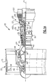
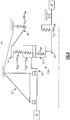
- FIG. 1 schematically illustrates a gas turbine engine 20.
- the gas turbine engine 20 is disclosed herein as a two-spool turbofan that generally incorporates a fan section 22, a compressor section 24, a combustor section 26 and a turbine section 28.
- Alternative engines might include an augmentor section (not shown) among other systems or features.
- the fan section 22 drives air along a bypass flow path B in a bypass duct defined within a nacelle 15, while the compressor section 24 drives air along a core flow path C for compression and communication into the combustor section 26 then expansion through the turbine section 28.
- the exemplary engine 20 generally includes a low speed spool 30 and a high speed spool 32 mounted for rotation about an engine central longitudinal axis A relative to an engine static structure 36 via several bearing systems 38. It should be understood that various bearing systems 38 at various locations may alternatively or additionally be provided, and the location of bearing systems 38 may be varied as appropriate to the application.
- the low speed spool 30 generally includes an inner shaft 40 that interconnects a fan 42, a low pressure compressor 44 and a low pressure turbine 46.
- the inner shaft 40 is connected to the fan 42 through a speed change mechanism, which in exemplary gas turbine engine 20 is illustrated as a geared architecture 48 to drive the fan 42 at a lower speed than the low speed spool 30.
- the high speed spool 32 includes an outer shaft 50 that interconnects a high pressure compressor 52 and high pressure turbine 54.
- a combustor 56 is arranged in exemplary gas turbine 20 between the high pressure compressor 52 and the high pressure turbine 54.
- a mid-turbine frame 57 of the engine static structure 36 is arranged generally between the high pressure turbine 54 and the low pressure turbine 46.
- the mid-turbine frame 57 further supports bearing systems 38 in the turbine section 28.
- the inner shaft 40 and the outer shaft 50 are concentric and rotate via bearing systems 38 about the engine central longitudinal axis A which is collinear with their longitudinal axes.
- the core airflow is compressed by the low pressure compressor 44 then the high pressure compressor 52, mixed and burned with fuel in the combustor 56, then expanded over the high pressure turbine 54 and low pressure turbine 46.
- the mid-turbine frame 57 includes airfoils 59 which are in the core airflow path C.
- the turbines 46, 54 rotationally drive the respective low speed spool 30 and high speed spool 32 in response to the expansion.
- gear system 48 may be located aft of combustor section 26 or even aft of turbine section 28, and fan section 22 may be positioned forward or aft of the location of gear system 48.
- the engine 20 in one example is a high-bypass geared aircraft engine.
- the engine 20 bypass ratio is greater than about six (6:1), with an example embodiment being greater than about ten (10:1)
- the geared architecture 48 is an epicyclic gear train, such as a planetary gear system or other gear system, with a gear reduction ratio of greater than about 2.3
- the low pressure turbine 46 has a pressure ratio that is greater than about five (5:1).
- the engine 20 bypass ratio is greater than about ten (10:1)
- the fan diameter is significantly larger than that of the low pressure compressor 44
- the low pressure turbine 46 has a pressure ratio that is greater than about five (5:1).
- Low pressure turbine 46 pressure ratio is pressure measured prior to inlet of low pressure turbine 46 as related to the pressure at the outlet of the low pressure turbine 46 prior to an exhaust nozzle.
- the geared architecture 48 may be an epicycle gear train, such as a planetary gear system or other gear system, with a gear reduction ratio of greater than about 2.3:1. It should be understood, however, that the above parameters are only exemplary of one embodiment of a geared architecture engine and that the present invention is applicable to other gas turbine engines including direct drive turbofans.
- the fan section 22 of the engine 20 is designed for a particular flight condition -- typically cruise at about 0.8 Mach and about 35,000 feet (10,670 metres).
- the flight condition of 0.8 Mach and 35,000 ft, with the engine at its best fuel consumption - also known as "bucket cruise Thrust Specific Fuel Consumption ('TSFC')" - is the industry standard parameter of lbm of fuel being burned divided by lbf of thrust the engine produces at that minimum point.
- “Low fan pressure ratio” is the pressure ratio across the fan blade alone, without a Fan Exit Guide Vane (“FEGV”) system.
- the low fan pressure ratio as disclosed herein according to one non-limiting embodiment is less than about 1.45.
- Low corrected fan tip speed is the actual fan tip speed in ft/sec divided by an industry standard temperature correction of [(Tram °R) / (518.7 °R)] 0.5 .
- the "Low corrected fan tip speed” as disclosed herein according to one non-limiting embodiment is less than about 1150 ft / second (350.5 m/s).
- the core airflow is compressed by the low pressure compressor 44 then the high pressure compressor 52, mixed and burned with fuel in the combustor 56, then expanded over the high pressure turbine 54 and low pressure turbine 46.
- the turbines 46, 54 rotationally drive the respective low speed spool 30 and high speed spool 32 in response to the expansion of the airflow passing therethrough.
- the amount of thrust that can be produced by a particular turbine section compared to how compact the turbine section is, is referred to as the power density, or the force density, of the turbine section, and is derived by the flat-rated Sea Level Take-Off (SLTO) thrust divided by the volume of the entire turbine section.
- the example volume is determined from an inlet of the high pressure turbine 54 to an exit of the low pressure turbine 46.
- each of the low pressure and high pressure turbines 46, 54 is made more compact. That is, the high pressure turbine 54 and the low pressure turbine 46 are made with a shorter axial length, and the spacing between each of the turbines 46, 54 is decreased, thereby decreasing the volume of the turbine section 28.
- the power density in the disclosed gas turbine engine 20 including the gear driven fan section 22 is greater than those provided in prior art gas turbine engine including a gear driven fan.
- the power density is greater than or equal to about 1.5 lbf/in 3 (407.1 kN/m 3 ). In further embodiments, the power density is greater than or equal to about 2.0 lbf/in 3 (542.9 kN/m 3 ). In further embodiments, the power density is greater than or equal to about 3.0 lbf/in3 (814.3 kN/m 3 ). In further embodiments, the power density is greater than or equal to about 4.0 lbf/in 3 (1086 kN/m 3 ). In further embodiments, the power density is less than or equal to about 5.5 lbf/in 3 (1493 kN/m 3 ).
- FIG. 1B With continued reference to Figure 1A , relative rotations between components of example disclosed engine architecture 100 are schematically shown.
- the fan 42 is connected, through the gearbox 48, to the low spool 30 to which the low pressure compressor 44 and the low pressure turbine 46 are connected.
- the high pressure compressor 52 and the high pressure turbine 54 are connected to a common shaft forming the high spool 32.
- the high spool 32 rotates opposite the direction of rotation of the fan 42 (illustrated in Figure 1B as the "+” direction.)
- the low spool 30 rotates in the same direction as the fan 42 (illustrated in Figure 1B as the "-” direction.)
- the high pressure turbine 54 and the low pressure turbine 46, along with the mid-turbine frame 57 together forms the turbine section 28 of the gas turbine engine 20.
- Other relative rotation directions between the two spools and the fan come within the scope of this disclosure.
- One disclosed example speed change device 48 has a gear reduction ratio exceeding 2.3:1, meaning that the low pressure turbine 46 turns at least 2.3 times faster than the fan 42.
- An example disclosed speed change device is an epicyclical gearbox of a planet type, where the input is to the center "sun" gear 260. Planet gears 262 (only one shown) around the sun gear 260 rotate and are spaced apart by a carrier 264 that rotates in a direction common to the sun gear 260.
- the fan 42 is attached to and driven by the carrier 264 such that the direction of rotation of the fan 42 is the same as the direction of rotation of the carrier 264 that, in turn, is the same as the direction of rotation of the input sun gear 260. Accordingly, the low pressure compressor 44 and the low pressure turbine 46 counter-rotate relative to the high pressure compressor 52 and the high pressure turbine 54.
- the mid-turbine frame 57 contributes to the overall compactness of the turbine section 28.
- the airfoil 59 of the mid-turbine frame 57 surrounds internal bearing support structures and oil tubes that are cooled. The airfoil 59 also directs flow around the internal bearing support structures and oil tubes for streamlining the high speed exhaust gas flow. Additionally, the airfoil 59 directs flow exiting the high pressure turbine 54 to a proper angle desired to promote increased efficiency of the low pressure turbine 46.
- Flow exiting the high pressure turbine 54 has a significant component of tangential swirl.
- the flow direction exiting the high pressure turbine 54 is set almost ideally for the blades in a first stage of the low pressure turbine 46 for a wide range of engine power settings.
- the aerodynamic turning function of the mid turbine frame 57 can be efficiently achieved without dramatic additional alignment of airflow exiting the high pressure turbine 54.
- the example turbine section 28 volume is schematically shown and includes first, second and third stages 46A, 46B and 46C.
- Each of the stages 46A, 46B and 46C includes a corresponding plurality of blades 212 and vanes 214.
- the example turbine section further includes an example air-turning vane 220 between the low and high turbines 54, 46 that has a modest camber to provide a small degree of redirection and achieve a desired flow angle relative to blades 212 of the first stage 46a of the low pressure turbine 46.
- the disclosed vane 220 could not efficiently perform the desired airflow function if the low and high pressure turbines 54, 46 rotated in a common direction.
- the example mid-turbine frame 57 includes multiple air turning vanes 220 in a row that direct air flow exiting the high pressure turbine 54 and ensure that air is flowing in the proper direction and with the proper amount of swirl. Because the disclosed turbine section 28 is more compact than previously utilized turbine sections, air has less distance to travel between exiting the mid-turbine frame 57 and entering the low pressure turbine 46. The smaller axial travel distance results in a decrease in the amount of swirl lost by the airflow during the transition from the mid-turbine frame 57 to the low pressure turbine 46, and allows the vanes 220 of the mid-turbine frame 57 to function as inlet guide vanes of the low pressure turbine 46.
- the mid-turbine frame 57 also includes a strut 221 providing structural support to both the mid-turbine frame 57 and to the engine housing.
- the mid-turbine frame 57 is much more compact by encasing the strut 221 within the vane 220, thereby decreasing the length of the mid-turbine frame 57.
- the inclusion of the speed change device 48 provides a gear reduction ratio, and thus the speed of the low pressure turbine 46 and low pressure compressor 44 components may be increased. More specifically, for a given fan diameter and fan tip speed, increases in gear ratios provide for a faster turning turbine that, in turn, provides for an increasingly compact turbine and increased thrust to volume ratios of the turbine section 28. By increasing the gear reduction ratio, the speed at which the low pressure compressor 44 and the low pressure turbine 46 turn, relative to the speed of the fan 42, is increased.
- Increases in rotational speeds of the gas turbine engine 20 components increases overall efficiency, thereby providing for reductions in the diameter and the number of stages of the low pressure compressor 44 and the low pressure turbine 46 that would otherwise be required to maintain desired flow characteristics of the air flowing through the core flow path C.
- the axial length of each of the low pressure compressor 44 and the low pressure turbine 46 can therefore be further reduced due to efficiencies gained from increased speed provided by an increased gear ratio.
- the reduction in the diameter and the stage count of the turbine section 28 increases the compactness and provides for an overall decrease in required axial length of the example gas turbine engine 20.
- the example turbine section 28 (including the high pressure turbine 54, the mid-turbine frame 57, and the low pressure turbine 46) is made more compact than traditional turbine engine designs, thereby decreasing the length of the turbine section 28 and the overall length of the gas turbine engine 20.
- Examples of materials and processes within the contemplation of this disclosure for the air-turning vane 220, the low pressure turbine blades 212, and the vanes 214 include materials with directionally solidified grains to provided added strength in a span-wise direction.
- An example method for creating a vane 220, 214 or turbine blade 212 having directionally solidified grains can be found in U.S. Applications No. 13/290667 , and U.S. Patent Nos. 7338259 and 7871247 .
- a further, engine embodiment utilizes a cast, hollow blade 212 or vane 214 with cooling air introduced at the leading edge of the blade/vane and a trailing edge discharge of the cooling air.
- Another embodiment uses an internally cooled blade 212 or vane 214 with film cooling holes.
- An additional engine embodiment utilizes an aluminum lithium material for construction of a portion of the low pressure turbine 46.
- the example low pressure turbine 46 may also be constructed utilizing at a powdered metal disc or rotor.
- one or more rows of turbine blades 212 of the low pressure turbine 46 can be constructed using a single crystal blade material.
- Single crystal constructions oxidize at higher temperatures as compared to non-single crystal constructions and thus can withstand higher temperature airflow.
- Higher temperature capability of the turbine blades 212 provide for a more efficient low pressure turbine 46 that may be further reduced in size.
- the low pressure turbine 46 includes three turbine stages 46a, 46b, and 46c
- the low pressure turbine 46 can be modified to include up to six turbine stages. Increasing the number of low pressure turbine stages 46a, 46b, 46c at constant thrust slightly reduces the thrust density of the turbine section 28 but also increases power available to drive the low pressure compressor and the fan section 22.
- example turbine blades may be internally cooled to allow the material to retain a desired strength at higher temperatures and thereby perform as desired in view of the increased centrifugal force generated by the compact configuration while also withstanding the higher temperatures created by adding low pressure compressor 44 stages and increasing fan tip diameter.
- Each of the disclosed embodiments enables the low pressure turbine 46 to be more compact and efficient, while also improving radial alignment to the high pressure turbine 54. Improved radial alignment between the low and high pressure turbines 54, 46 increases efficiencies that can offset any increases in manufacturing costs incurred by including the air turning vane 220 of the mid-turbine frame 57.
- the overall size of the turbine section 28 has been greatly reduced, thereby enhancing the engine's power density. Further, as a result of the improvement in power density, the engine's overall propulsive efficiency has been improved.
- An exit area 400 is shown, in Figure 1D and Figure 1A , at the exit location for the high pressure turbine section 54.
- An exit area for the low pressure turbine section is defined at exit 401 for the low pressure turbine section.
- the turbine engine 20 may be counter-rotating. This means that the low pressure turbine section 46 and low pressure compressor section 44 rotate in one direction, while the high pressure spool 32, including high pressure turbine section 54 and high pressure compressor section 52 rotate in an opposed direction.
- the gear reduction 48 which may be, for example, an epicyclic transmission (e.g., with a sun, ring, and star gears), is selected such that the fan 42 rotates in the same direction as the high spool 32.
- PQ Performance quantity
- PQ ltp A lpt ⁇ V lpt 2
- PQ htp A hpt ⁇ V hpt 2
- a lpt is the area of the low pressure turbine section at the exit thereof (e.g., at 401)
- V lpt is the speed of the low pressure turbine section
- a hpt is the area of the high pressure turbine section at the exit thereof (e.g., at 400)
- V hpt is the speed of the low pressure turbine section.
- a lpt ⁇ V lpt 2 / A hpt ⁇ V hpt 2 PQ ltp / PQ hpt
- the areas of the low and high pressure turbine sections are 557.9 in 2 (3,599 cm 2 ) and 90.67 in 2 (585 cm 2 ), respectively. Further, the speeds of the low and high pressure turbine sections are 10179 rpm and 24346 rpm, respectively.
- the ratio was about 1.5.
- PQ ltp/ PQ hpt ratios in the 0.5 to 1.5 range a very efficient overall gas turbine engine is achieved. More narrowly, PQ ltp/ PQ hpt ratios of above or equal to about 0.8 are more efficient. Even more narrowly, PQ ltp/ PQ hpt ratios above or equal to 1.0 are even more efficient.
- the turbine section can be made much smaller than in the prior art, both in diameter and axial length. In addition, the efficiency of the overall engine is greatly increased.
- the low pressure compressor section is also improved with this arrangement, and behaves more like a high pressure compressor section than a traditional low pressure compressor section. It is more efficient than the prior art, and can provide more work in fewer stages.
- the low pressure compressor section may be made smaller in radius and shorter in length while contributing more toward achieving the overall pressure ratio design target of the engine.
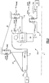
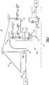
- the geared architecture 48 generally includes a fan drive gear system (FDGS) 60 driven by the low speed spool 30 (illustrated schematically) through an input coupling 62.
- the input coupling 62 both transfers torque from the low speed spool 30 to the geared architecture 48 and facilitates the segregation of vibrations and other transients therebetween.
- the FDGS 60 may include an epicyclic gear system which may be, for example, a star system or a planet system.
- the input coupling 62 may include an interface spline 64 joined, by a gear spline 66, to a sun gear 68 of the FDGS 60.
- the sun gear 68 is in meshed engagement with multiple planet gears 70, of which the illustrated planet gear 70 is representative.
- Each planet gear 70 is rotatably mounted in a planet carrier 72 by a respective planet journal bearing 75.
- Rotary motion of the sun gear 68 urges each planet gear 70 to rotate about a respective longitudinal axis P.
- the gears may be generally as shown schematically in Figure 1B .
- Each planet gear 70 is also in meshed engagement with rotating ring gear 74 that is mechanically connected to a fan shaft 76. Since the planet gears 70 mesh with both the rotating ring gear 74 as well as the rotating sun gear 68, the planet gears 70 rotate about their own axes to drive the ring gear 74 to rotate about engine axis A. The rotation of the ring gear 74 is conveyed to the fan 42 ( Figure 1 ) through the fan shaft 76 to thereby drive the fan 42 at a lower speed than the low speed spool 30. It should be understood that the described geared architecture 48 is but a single non-limiting embodiment and that various other geared architectures will alternatively benefit herefrom.
- a flexible support 78 supports the planet carrier 72 to at least partially support the FDGS 60A with respect to the static structure 36 such as a front center body which facilitates the segregation of vibrations and other transients therebetween.
- the static structure 36 such as a front center body which facilitates the segregation of vibrations and other transients therebetween.
- various gas turbine engine case structures may alternatively or additionally provide the static structure and flexible support 78.
- lateral refers to a perpendicular direction with respect to the axis of rotation A and the term “transverse” refers to a pivotal bending movement with respect to the axis of rotation A so as to absorb deflections which may be otherwise applied to the FDGS 60.
- the static structure 36 may further include a number 1 and 1.5 bearing support static structure 82 which is commonly referred to as a "K-frame" which supports the number 1 and number 1.5 bearing systems 38A. 38B.
- K-frame bearing support defines a lateral stiffness (represented as Kframe in Figure 3 ) and a transverse stiffness (represented as Kframe BEND in Figure 3 ) as the referenced factors in this non-limiting embodiment.
- the lateral stiffness (KFS; KIC) of both the flexible support 78 and the input coupling 62 are each less than about 11% of the lateral stiffness (Kframe). That is, the lateral stiffness of the entire FDGS 60 is controlled by this lateral stiffness relationship.
- the transverse stiffness of both the flexible support 78 and the input coupling 62 are each less than about 11% of the transverse stiffness (Kframe BEND ). That is, the transverse stiffness of the entire FDGS 60 is controlled by this transverse stiffness relationship.
- a FDGS 60B includes a flexible support 78' that supports a rotationally fixed ring gear 74'.
- the fan shaft 76' is driven by the planet carrier 72' in the schematically illustrated planet system which otherwise generally follows the star system architecture of Figure 3 .
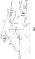
- lateral stiffness relationship within a FDGS 60C itself is schematically represented.
- the lateral stiffness (KIC) of an input coupling 62, a lateral stiffness (KFS) of a flexible support 78, a lateral stiffness (KRG) of a ring gear 74 and a lateral stiffness (KJB) of a planet journal bearing 75 are controlled with respect to a lateral stiffness (KGM) of a gear mesh within the FDGS 60.
- the stiffness (KGM) may be defined by the gear mesh between the sun gear 68 and the multiple planet gears 70.
- the lateral stiffness (KGM) within the FDGS 60 is the referenced factor and the static structure 82' rigidly supports the fan shaft 76. That is, the fan shaft 76 is supported upon bearing systems 38A, 38B which are essentially rigidly supported by the static structure 82'.
- the lateral stiffness (KJB) may be mechanically defined by, for example, the stiffness within the planet journal bearing 75 and the lateral stiffness (KRG) of the ring gear 74 may be mechanically defined by, for example, the geometry of the ring gear wings 74L, 74R ( Figure 2 ).
- the lateral stiffness (KRG) of the ring gear 74 is less than about 12% of the lateral stiffness (KGM) of the gear mesh; the lateral stiffness (KFS) of the flexible support 78 is less than about 8% of the lateral stiffness (KGM) of the gear mesh; the lateral stiffness (KJB) of the planet journal bearing 75 is less than or equal to the lateral stiffness (KGM) of the gear mesh; and the lateral stiffness (KIC) of an input coupling 62 is less than about 5% of the lateral stiffness (KGM) of the gear mesh.
- FIG. 6 another non-limiting embodiment of a lateral stiffness relationship within a FDGS 60D itself are schematically illustrated for a planetary gear system architecture, which otherwise generally follows the star system architecture of Figure 5 .
- lateral stiffness relationships may be utilized as well.
- the lateral stiffness of each of structural components may be readily measured as compared to film stiffness and spline stiffness which may be relatively difficult to determine.
- the flex mount facilitates alignment to increase system life and reliability.
- the lateral flexibility in the flexible support and input coupling allows the FDGS to essentially 'float' with the fan shaft during maneuvers. This allows: (a) the torque transmissions in the fan shaft, the input coupling and the flexible support to remain constant during maneuvers; (b) maneuver induced lateral loads in the fan shaft (which may otherwise potentially misalign gears and damage teeth) to be mainly reacted to through the number 1 and 1.5 bearing support K-frame; and (c) both the flexible support and the input coupling to transmit small amounts of lateral loads into the FDGS.
- the splines, gear tooth stiffness, journal bearings, and ring gear ligaments are specifically designed to minimize gear tooth stress variations during maneuvers.
- the other connections to the FDGS are flexible mounts (turbine coupling, case flex mount). These mount spring rates have been determined from analysis and proven in rig and flight testing to isolate the gears from engine maneuver loads.
- the planet journal bearing spring rate may also be controlled to support system flexibility.
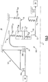
- Figure 7 is similar to Figure 5 but shows the transverse stiffness relationships within the FDGS 60C (for a star system architecture).
- the transverse stiffness (KIC BEND ) of the input coupling 62, a transverse stiffness (KFS BEND ) of the flexible support 78, a transverse stiffness (KRG BEND ) of the ring gear 74 and a transverse stiffness (KJB BEND ) of the planet journal bearing 75 are controlled with respect to a transverse stiffness (KGM BEND ) of the gear mesh within the FDGS 60.
- the stiffness (KGM BEND ) may be defined by the gear mesh between the sun gear 68 and the multiple planet gears 70.
- the transverse stiffness (KGM BEND ) within the FDGS 60 is the referenced factor and the static structure 82' rigidly supports the fan shaft 76. That is, the fan shaft 76 is supported upon bearing systems 38A, 38B which are essentially rigidly supported by the static structure 82'.
- the transverse stiffness (KJB BEND ) may be mechanically defined by, for example, the stiffness within the planet journal bearing 75 and the transverse stiffness (KRG BEND ) of the ring gear 74 may be mechanically defined by, for example, the geometry of the ring gear wings 74L, 74R ( Figure 2 ).
- the transverse stiffness (KRG BEND ) of the ring gear 74 is less than about 12% of the transverse stiffness (KGM BEND ) of the gear mesh; the transverse stiffness (KFS BEND ) of the flexible support 78 is less than about 8% of the transverse stiffness (KGM BEND ) of the gear mesh; the transverse stiffness (KJB BEND ) of the planet journal bearing 75 is less than or equal to the transverse stiffness (KGM BEND ) of the gear mesh; and the transverse stiffness (KIC BEND ) of an input coupling 62 is less than about 5% of the transverse stiffness (KGM BEND ) of the gear mesh.
- Figure 8 is similar to Figure 6 but shows the transverse stiffness relationship within the FDGS 60D for the planetary gear system architecture.
Claims (14)
- Moteur à turbine à gaz (20) comprenant :un arbre de soufflante (76) entraînant une soufflante (42) ;un cadre (82) qui supporte ledit arbre de soufflante (76) ;une pluralité d'engrenages (48) pour entraîner ledit arbre de soufflante (76) ;un support flexible (78) qui supporte au moins partiellement ladite pluralité d'engrenages (48), ledit support flexible (78) ayant une rigidité moindre que celle dudit cadre (82) ;une première bobine (30) ;une première section de turbine (46) configurée pour entraîner ladite première bobine (30), ladite première bobine (30) fournissant une entrée d'entraînement dans ladite pluralité d'engrenages (48) ; etune deuxième bobine (32) ; etune deuxième section de turbine (54) configurée pour entraîner ladite deuxième bobine (32), dans lequel ladite première section de turbine (46) comporte une première surface de sortie (400) au niveau d'un premier point de sortie et ladite première bobine (30) est configurée pour tourner à une première vitesse, ladite deuxième section de turbine (54) comporte une deuxième surface de sortie (401) au niveau d'un deuxième point de sortie et ladite deuxième bobine (32) est configurée pour tourner à une deuxième vitesse, qui est plus rapide que la première vitesse, une première quantité de performance est définie comme le produit de la première vitesse mise au carré et de la première surface de sortie (400) et une deuxième quantité de performance est définie comme le produit de la deuxième vitesse mise au carré et de la deuxième surface de sortie (401),caractérisé en ce que :un rapport de la première quantité de performance sur la deuxième quantité de performance est égal à 0,8 ou est entre 0,8 et 1,5.
- Moteur à turbine à gaz (20) selon la revendication 1, dans lequel ledit rapport est supérieur ou égal à 1,0.
- Moteur à turbine à gaz (20) selon la revendication 1 ou 2, dans lequel un rapport d'une poussée fournie par ledit moteur (20), sur un volume d'une section de turbine (28) incluant ladite première section de turbine (46) et ladite deuxième section de turbine (54), est supérieur ou égal à 1,5 lb/pouce3 (407,1 kN/m3) et inférieur ou égal à 5,5 lb/pouce3 (1493 kN/m3), dans lequel ladite poussée est une poussée statique détarée, de décollage au niveau de la mer.
- Moteur à turbine à gaz (20) selon la revendication 3, dans lequel ledit rapport est supérieur ou égal à 2,0 lb/pouce3 (542,9 kN/m3), ou supérieur ou égal à 4,0 lb/pouce3 (1086 kN/m3).
- Moteur à turbine à gaz (20) selon une quelconque revendication précédente, dans lequel ladite première section de turbine (46) comporte au moins trois étages (46A, 46B, 46C).
- Moteur à turbine à gaz (20) selon une quelconque revendication précédente, dans lequel ladite première section de turbine (46) comporte jusqu'à six étages (46A, 46B, 46C).
- Moteur à turbine à gaz (20) selon une quelconque revendication précédente, dans lequel ladite deuxième section de turbine (54) comporte deux étages.
- Moteur à turbine à gaz (20) selon une quelconque revendication précédente, dans lequel un rapport de pression à travers la première section de turbine (46) est supérieur à 5:1.
- Moteur à turbine à gaz (20) selon une quelconque revendication précédente, dans lequel ledit cadre (82) inclut une rigidité latérale de cadre et une rigidité transversale de cadre, et ledit support flexible (78) inclut une rigidité transversale de support flexible et une rigidité latérale de support flexible, et ladite rigidité latérale de support flexible est inférieure à ladite rigidité latérale de cadre et ladite rigidité transversale de support flexible est inférieure à ladite rigidité transversale de cadre.
- Moteur à turbine à gaz (20) selon la revendication 9, dans lequel un couplage flexible (62) connecte au moins l'un de ladite pluralité d'engrenages (48) à entraîner par ladite première section de turbine ou section de turbine basse-pression (46).
- Moteur à turbine à gaz (20) selon la revendication 10, dans lequel ledit couplage flexible (62) présente une rigidité latérale de couplage flexible et une rigidité transversale de couplage flexible, et ladite rigidité latérale de couplage flexible est inférieure à ladite rigidité latérale de cadre, et ladite rigidité transversale de couplage flexible est inférieure de ladite rigidité transversale de cadre.
- Moteur à turbine à gaz (20) selon l'une quelconque des revendications 9 à 11, dans lequel ladite pluralité d'engrenages (48) inclue un engrènement qui définit une rigidité latérale d'engrènement et une rigidité transversale d'engrènement, ladite rigidité latérale d'engrènement est supérieure à ladite rigidité latérale de support flexible et ladite rigidité transversale d'engrènement est supérieure à ladite rigidité transversale de support flexible.
- Procédé de fonctionnement d'un moteur à turbine à gaz (20) présentant les caractéristiques selon une quelconque revendication précédente, dans lequel le procédé comprend les étapes consistant à :faire tourner la première bobine (30) à ladite première vitesse ; etfaire tourner la deuxième bobine (32) à ladite deuxième vitesse, de telle sorte que le rapport de la première quantité de performance sur la deuxième quantité de performance est égal à 0,8 ou se situe entre 0,8 et 1,5.
- Procédé selon la revendication 13, dans lequel le rapport de la première quantité de performance sur la deuxième quantité de performance est supérieur ou égal à 1,0.
Priority Applications (5)
| Application Number | Priority Date | Filing Date | Title |
|---|---|---|---|
| EP15175205.2A EP2949882B1 (fr) | 2013-06-03 | 2014-02-17 | Architecture a engrenages pour l'entrainement d'une soufflante par une turbine de petit volume et grande vitesse |
| EP18191333.6A EP3467273A1 (fr) | 2013-06-03 | 2014-02-17 | Architecture à engrenage pour turbines d'entraînement de ventilateur de petit volume et à grande vitesse |
| EP15175203.7A EP2949881B1 (fr) | 2013-06-03 | 2014-02-17 | ARCHITECTURE À ENGRENAGE POUR l'ENTRAINEMENT D'UNE SOUFFLANTE PAR UNE TURBINE DE PETIT VOLUME ET À GRANDE VITESSE |
| EP18191325.2A EP3467272A1 (fr) | 2013-06-03 | 2014-02-17 | ARCHITECTURE À ENGRENAGE POUR l'ENTRAINEMENT D'UNE SOUFFLANTE PAR UNE TURBINE DE PETIT VOLUME ET À GRANDE VITESSE |
| EP23160056.0A EP4209661A3 (fr) | 2013-06-03 | 2014-02-17 | Architecture à engrenages pour turbine d'entraînement de ventilateur à grande vitesse et à petit volume |
Applications Claiming Priority (1)
| Application Number | Priority Date | Filing Date | Title |
|---|---|---|---|
| US13/908,177 US9631558B2 (en) | 2012-01-03 | 2013-06-03 | Geared architecture for high speed and small volume fan drive turbine |
Related Child Applications (7)
| Application Number | Title | Priority Date | Filing Date |
|---|---|---|---|
| EP15175205.2A Division EP2949882B1 (fr) | 2013-06-03 | 2014-02-17 | Architecture a engrenages pour l'entrainement d'une soufflante par une turbine de petit volume et grande vitesse |
| EP15175205.2A Division-Into EP2949882B1 (fr) | 2013-06-03 | 2014-02-17 | Architecture a engrenages pour l'entrainement d'une soufflante par une turbine de petit volume et grande vitesse |
| EP18191333.6A Division EP3467273A1 (fr) | 2013-06-03 | 2014-02-17 | Architecture à engrenage pour turbines d'entraînement de ventilateur de petit volume et à grande vitesse |
| EP23160056.0A Division EP4209661A3 (fr) | 2013-06-03 | 2014-02-17 | Architecture à engrenages pour turbine d'entraînement de ventilateur à grande vitesse et à petit volume |
| EP18191325.2A Division EP3467272A1 (fr) | 2013-06-03 | 2014-02-17 | ARCHITECTURE À ENGRENAGE POUR l'ENTRAINEMENT D'UNE SOUFFLANTE PAR UNE TURBINE DE PETIT VOLUME ET À GRANDE VITESSE |
| EP15175203.7A Division-Into EP2949881B1 (fr) | 2013-06-03 | 2014-02-17 | ARCHITECTURE À ENGRENAGE POUR l'ENTRAINEMENT D'UNE SOUFFLANTE PAR UNE TURBINE DE PETIT VOLUME ET À GRANDE VITESSE |
| EP15175203.7A Division EP2949881B1 (fr) | 2013-06-03 | 2014-02-17 | ARCHITECTURE À ENGRENAGE POUR l'ENTRAINEMENT D'UNE SOUFFLANTE PAR UNE TURBINE DE PETIT VOLUME ET À GRANDE VITESSE |
Publications (2)
| Publication Number | Publication Date |
|---|---|
| EP2811120A1 EP2811120A1 (fr) | 2014-12-10 |
| EP2811120B1 true EP2811120B1 (fr) | 2017-07-12 |
Family
ID=50238097
Family Applications (6)
| Application Number | Title | Priority Date | Filing Date |
|---|---|---|---|
| EP18191333.6A Withdrawn EP3467273A1 (fr) | 2013-06-03 | 2014-02-17 | Architecture à engrenage pour turbines d'entraînement de ventilateur de petit volume et à grande vitesse |
| EP14155460.0A Revoked EP2811120B1 (fr) | 2013-06-03 | 2014-02-17 | Architecture à engrenages pour l'entraînement d'une soufflante par une turbine de petit volume et grande vitesse |
| EP15175205.2A Revoked EP2949882B1 (fr) | 2013-06-03 | 2014-02-17 | Architecture a engrenages pour l'entrainement d'une soufflante par une turbine de petit volume et grande vitesse |
| EP23160056.0A Pending EP4209661A3 (fr) | 2013-06-03 | 2014-02-17 | Architecture à engrenages pour turbine d'entraînement de ventilateur à grande vitesse et à petit volume |
| EP15175203.7A Revoked EP2949881B1 (fr) | 2013-06-03 | 2014-02-17 | ARCHITECTURE À ENGRENAGE POUR l'ENTRAINEMENT D'UNE SOUFFLANTE PAR UNE TURBINE DE PETIT VOLUME ET À GRANDE VITESSE |
| EP18191325.2A Withdrawn EP3467272A1 (fr) | 2013-06-03 | 2014-02-17 | ARCHITECTURE À ENGRENAGE POUR l'ENTRAINEMENT D'UNE SOUFFLANTE PAR UNE TURBINE DE PETIT VOLUME ET À GRANDE VITESSE |
Family Applications Before (1)
| Application Number | Title | Priority Date | Filing Date |
|---|---|---|---|
| EP18191333.6A Withdrawn EP3467273A1 (fr) | 2013-06-03 | 2014-02-17 | Architecture à engrenage pour turbines d'entraînement de ventilateur de petit volume et à grande vitesse |
Family Applications After (4)
| Application Number | Title | Priority Date | Filing Date |
|---|---|---|---|
| EP15175205.2A Revoked EP2949882B1 (fr) | 2013-06-03 | 2014-02-17 | Architecture a engrenages pour l'entrainement d'une soufflante par une turbine de petit volume et grande vitesse |
| EP23160056.0A Pending EP4209661A3 (fr) | 2013-06-03 | 2014-02-17 | Architecture à engrenages pour turbine d'entraînement de ventilateur à grande vitesse et à petit volume |
| EP15175203.7A Revoked EP2949881B1 (fr) | 2013-06-03 | 2014-02-17 | ARCHITECTURE À ENGRENAGE POUR l'ENTRAINEMENT D'UNE SOUFFLANTE PAR UNE TURBINE DE PETIT VOLUME ET À GRANDE VITESSE |
| EP18191325.2A Withdrawn EP3467272A1 (fr) | 2013-06-03 | 2014-02-17 | ARCHITECTURE À ENGRENAGE POUR l'ENTRAINEMENT D'UNE SOUFFLANTE PAR UNE TURBINE DE PETIT VOLUME ET À GRANDE VITESSE |
Country Status (6)
| Country | Link |
|---|---|
| EP (6) | EP3467273A1 (fr) |
| JP (1) | JP5732562B2 (fr) |
| CN (1) | CN104213985B (fr) |
| CA (1) | CA2845618C (fr) |
| RU (1) | RU2639821C2 (fr) |
| SG (1) | SG10201401514UA (fr) |
Cited By (1)
| Publication number | Priority date | Publication date | Assignee | Title |
|---|---|---|---|---|
| EP3467272A1 (fr) | 2013-06-03 | 2019-04-10 | United Technologies Corporation | ARCHITECTURE À ENGRENAGE POUR l'ENTRAINEMENT D'UNE SOUFFLANTE PAR UNE TURBINE DE PETIT VOLUME ET À GRANDE VITESSE |
Families Citing this family (17)
| Publication number | Priority date | Publication date | Assignee | Title |
|---|---|---|---|---|
| US9631558B2 (en) | 2012-01-03 | 2017-04-25 | United Technologies Corporation | Geared architecture for high speed and small volume fan drive turbine |
| US9239012B2 (en) | 2011-06-08 | 2016-01-19 | United Technologies Corporation | Flexible support structure for a geared architecture gas turbine engine |
| US9410608B2 (en) | 2011-06-08 | 2016-08-09 | United Technologies Corporation | Flexible support structure for a geared architecture gas turbine engine |
| US20130192263A1 (en) | 2012-01-31 | 2013-08-01 | Gabriel L. Suciu | Gas turbine engine with high speed low pressure turbine section |
| US10287914B2 (en) | 2012-01-31 | 2019-05-14 | United Technologies Corporation | Gas turbine engine with high speed low pressure turbine section and bearing support features |
| US10125693B2 (en) | 2012-04-02 | 2018-11-13 | United Technologies Corporation | Geared turbofan engine with power density range |
| US20160333786A1 (en) * | 2015-05-13 | 2016-11-17 | General Electric Company | System for supporting rotor shafts of an indirect drive turbofan engine |
| FR3039132B1 (fr) * | 2015-07-20 | 2017-08-11 | Airbus Operations Sas | Ensemble moteur a helice a axe horizontal pour aeronef |
| EP3165754A1 (fr) * | 2015-11-03 | 2017-05-10 | United Technologies Corporation | Moteur à turbine à gaz ayant une section basse pression haute vitesse et éléments de support de palier |
| CN105443270B (zh) * | 2015-12-29 | 2017-11-03 | 中国航空工业集团公司沈阳发动机设计研究所 | 一种航空涡轮风扇发动机 |
| US10364752B2 (en) * | 2016-05-17 | 2019-07-30 | General Electric Company | System and method for an integral drive engine with a forward main gearbox |
| US10815881B2 (en) | 2017-09-20 | 2020-10-27 | General Electric Company | Counter rotating turbine with reversing speed reduction assembly |
| GB201804128D0 (en) * | 2018-03-15 | 2018-05-02 | Rolls Royce Plc | Electrical power generator system |
| IT201800005822A1 (it) * | 2018-05-29 | 2019-11-29 | Attacco di un gruppo ingranaggio per un motore a turbina a gas | |
| CN113495001B (zh) * | 2020-04-02 | 2022-06-21 | 中国航发商用航空发动机有限责任公司 | 压气机盘腔卷吸流量比的测量装置及方法 |
| CN113833573B (zh) * | 2020-06-24 | 2022-08-16 | 中国航发商用航空发动机有限责任公司 | 双转子双支点燃气轮机 |
| US11428160B2 (en) * | 2020-12-31 | 2022-08-30 | General Electric Company | Gas turbine engine with interdigitated turbine and gear assembly |
Citations (4)
| Publication number | Priority date | Publication date | Assignee | Title |
|---|---|---|---|---|
| US6223616B1 (en) | 1999-12-22 | 2001-05-01 | United Technologies Corporation | Star gear system with lubrication circuit and lubrication method therefor |
| US7828682B2 (en) | 2006-05-11 | 2010-11-09 | Hansen Transmissions International N.V. | Gearbox for a wind turbine |
| EP2532858A2 (fr) | 2011-06-08 | 2012-12-12 | United Technologies Corporation | Structure de support flexible pour moteur de turbine à gaz à architecture à engrenages |
| US20130259653A1 (en) * | 2012-04-02 | 2013-10-03 | Frederick M. Schwarz | Geared turbofan engine with power density range |
Family Cites Families (18)
| Publication number | Priority date | Publication date | Assignee | Title |
|---|---|---|---|---|
| IL82840A0 (en) * | 1986-07-15 | 1987-12-20 | Savyon Diagnostics Ltd | Method and compositions for the determination of occult blood |
| US5433674A (en) | 1994-04-12 | 1995-07-18 | United Technologies Corporation | Coupling system for a planetary gear train |
| GB2322914B (en) * | 1997-03-05 | 2000-05-24 | Rolls Royce Plc | Ducted fan gas turbine engine |
| US7338259B2 (en) | 2004-03-02 | 2008-03-04 | United Technologies Corporation | High modulus metallic component for high vibratory operation |
| GB0406174D0 (en) * | 2004-03-19 | 2004-04-21 | Rolls Royce Plc | Turbine engine arrangement |
| US7631484B2 (en) * | 2006-03-13 | 2009-12-15 | Rollin George Giffin | High pressure ratio aft fan |
| US20070214795A1 (en) * | 2006-03-15 | 2007-09-20 | Paul Cooker | Continuous real time EGT margin control |
| US8585538B2 (en) * | 2006-07-05 | 2013-11-19 | United Technologies Corporation | Coupling system for a star gear train in a gas turbine engine |
| US7704178B2 (en) * | 2006-07-05 | 2010-04-27 | United Technologies Corporation | Oil baffle for gas turbine fan drive gear system |
| RU2330170C2 (ru) * | 2006-09-11 | 2008-07-27 | Открытое акционерное общество "Авиадвигатель" | Двухконтурный газотурбинный двигатель сверхвысокой степени двухконтурности |
| US7950237B2 (en) * | 2007-06-25 | 2011-05-31 | United Technologies Corporation | Managing spool bearing load using variable area flow nozzle |
| US8844265B2 (en) * | 2007-08-01 | 2014-09-30 | United Technologies Corporation | Turbine section of high bypass turbofan |
| US9631558B2 (en) | 2012-01-03 | 2017-04-25 | United Technologies Corporation | Geared architecture for high speed and small volume fan drive turbine |
| US9133729B1 (en) * | 2011-06-08 | 2015-09-15 | United Technologies Corporation | Flexible support structure for a geared architecture gas turbine engine |
| CA2789465C (fr) * | 2011-10-27 | 2016-08-09 | United Technologies Corporation | Architecture de corps central avant de moteur a turbine a gaz |
| CA2789325C (fr) * | 2011-10-27 | 2015-04-07 | United Technologies Corporation | Architecture de corps central avant de moteur a turbine a gaz |
| US20130192266A1 (en) | 2012-01-31 | 2013-08-01 | United Technologies Corporation | Geared turbofan gas turbine engine architecture |
| EP3467273A1 (fr) | 2013-06-03 | 2019-04-10 | United Technologies Corporation | Architecture à engrenage pour turbines d'entraînement de ventilateur de petit volume et à grande vitesse |
-
2014
- 2014-02-17 EP EP18191333.6A patent/EP3467273A1/fr not_active Withdrawn
- 2014-02-17 EP EP14155460.0A patent/EP2811120B1/fr not_active Revoked
- 2014-02-17 EP EP15175205.2A patent/EP2949882B1/fr not_active Revoked
- 2014-02-17 EP EP23160056.0A patent/EP4209661A3/fr active Pending
- 2014-02-17 EP EP15175203.7A patent/EP2949881B1/fr not_active Revoked
- 2014-02-17 EP EP18191325.2A patent/EP3467272A1/fr not_active Withdrawn
- 2014-03-05 JP JP2014042229A patent/JP5732562B2/ja active Active
- 2014-03-07 CN CN201410082009.1A patent/CN104213985B/zh active Active
- 2014-03-10 CA CA2845618A patent/CA2845618C/fr active Active
- 2014-03-24 RU RU2014110925A patent/RU2639821C2/ru active
- 2014-04-14 SG SG10201401514UA patent/SG10201401514UA/en unknown
Patent Citations (5)
| Publication number | Priority date | Publication date | Assignee | Title |
|---|---|---|---|---|
| US6223616B1 (en) | 1999-12-22 | 2001-05-01 | United Technologies Corporation | Star gear system with lubrication circuit and lubrication method therefor |
| US7828682B2 (en) | 2006-05-11 | 2010-11-09 | Hansen Transmissions International N.V. | Gearbox for a wind turbine |
| EP2532858A2 (fr) | 2011-06-08 | 2012-12-12 | United Technologies Corporation | Structure de support flexible pour moteur de turbine à gaz à architecture à engrenages |
| EP2532841A2 (fr) | 2011-06-08 | 2012-12-12 | United Technologies Corporation | Structure de support flexible pour moteur de turbine à gaz à architecture à engrenages |
| US20130259653A1 (en) * | 2012-04-02 | 2013-10-03 | Frederick M. Schwarz | Geared turbofan engine with power density range |
Non-Patent Citations (16)
| Title |
|---|
| "Learjet 31 and 35/36 TFE731-2 to -2C Engine Upgrade Program", HONEYWELL, September 2005 (2005-09-01), XP055481218 |
| "Sabreliner 65 TFE731-3 to -3D Engine Upgrade Program", HONEYWELL, October 2005 (2005-10-01), XP055481212 |
| "TFE731", GARRETT, 1987, XP055481195 |
| "Turbofan and Turbojet Engines Database Handbook", article ELODIE ROUX: "Chapter 1 List of variables", pages: 41 - 43, 464-469, XP055481222 |
| "Type certificate data sheet No. E6WE", DEPARTMENT OF TRANSPORTATION FEDERAL AVIATION ADMINISTRATION, 9 May 2000 (2000-05-09), XP055481226 |
| BRUCE E. WENDUS ET AL.: "Follow-On Technology Requirement Study for Advanced Subsonic Transport", NASA, August 2003 (2003-08-01), pages iii - 48, XP055279476 |
| C. RIEGLER ET AL.: "THE GEARED TURBOFAN TECHNOLOGY - OPPORTUNITES, CHALLENGED AND READINESS STATUS", PROCEEDINGS CEAS 2007, 11 September 2007 (2007-09-11), XP055195802 |
| C.N. REYNOLDS ET AL.: "Advanced prop-fan engine technology (APET) single- and counter- rotation gearbox/pitch change mechanism", NASA CONTRACTOR REPORT 168114, vol. 1, July 1985 (1985-07-01), XP055478590, Retrieved from the Internet <URL:https://ntrs.nasa.gov/archive/nasa/casi.ntrs.nasa.gov/19870019119.pdf> |
| D.E. GRAY ET AL.: "Energy Efficient Engine Preliminary Design and Integration Studies", NASA CR-135396, pages 1 - 366, XP055280688 |
| DALE RAUCH: "DESIGN STUDY OF AN AIR PUMP AND INTEGRAL LIFT ENGINE ALF-504 USING THE LYCOMING 502 CORE", NASA REPORT CR-120992, 31 July 1972 (1972-07-31), XP055273059, Retrieved from the Internet <URL:http://ntrs.nasa.gov/archive/nasa/casi.ntrs.nasa.gov/19730004744.pdf> [retrieved on 20160517] * |
| FATHI AHMAD: "Single vs. two stage high pressure turbine design of modern aero engines", INTERNATIONAL GAS TURBINE & AEROENGINE CONGRESS ET EXHIBITION, June 1999 (1999-06-01), XP055481234 |
| JACK D. MATTINGLY, ELEMENTS OF GAS TURBINE PROPULSION, 1996 |
| JOACHIM KURKZE: "Gas Turb 12 Design and Off-Design Performance of Gas Turbines", 2012, pages 5 - 312 |
| JOACHIM KURZKE: "Fundamental Differences Between Conventional and Geared Turbofans", PROCEEDINGS OF ASME TURBO EXPO 2009: POWER FOR LAND, SEA AND AIR, GT2009-59745, June 2009 (2009-06-01), pages 145 - 153, XP055481228 |
| MARK H. WATERS ET AL.: "Analysis of turbofan propulsion system weight and dimensions", NASA TM-X-73, vol. 199, 1977, pages 1 - 65, XP055306421 |
| MÉTHODOLOGIE DE MESURE ET DE CALCUL SUR LES MODÈLES TFE731-2, TFE731-3A ET TFE731- - 3D |
Cited By (1)
| Publication number | Priority date | Publication date | Assignee | Title |
|---|---|---|---|---|
| EP3467272A1 (fr) | 2013-06-03 | 2019-04-10 | United Technologies Corporation | ARCHITECTURE À ENGRENAGE POUR l'ENTRAINEMENT D'UNE SOUFFLANTE PAR UNE TURBINE DE PETIT VOLUME ET À GRANDE VITESSE |
Also Published As
| Publication number | Publication date |
|---|---|
| CA2845618A1 (fr) | 2014-05-22 |
| EP2949882A1 (fr) | 2015-12-02 |
| SG10201401514UA (en) | 2015-01-29 |
| RU2014110925A (ru) | 2015-09-27 |
| BR102014007285A2 (pt) | 2015-05-26 |
| CN104213985A (zh) | 2014-12-17 |
| EP2949881A1 (fr) | 2015-12-02 |
| JP5732562B2 (ja) | 2015-06-10 |
| EP3467273A1 (fr) | 2019-04-10 |
| CN104213985B (zh) | 2017-09-22 |
| EP4209661A3 (fr) | 2023-11-22 |
| JP2014234822A (ja) | 2014-12-15 |
| RU2639821C2 (ru) | 2017-12-22 |
| EP2811120A1 (fr) | 2014-12-10 |
| EP2949882B1 (fr) | 2017-08-23 |
| CA2845618C (fr) | 2015-06-02 |
| EP4209661A2 (fr) | 2023-07-12 |
| EP2949881B1 (fr) | 2018-08-29 |
| EP3467272A1 (fr) | 2019-04-10 |
Similar Documents
| Publication | Publication Date | Title |
|---|---|---|
| US11635043B2 (en) | Geared architecture for high speed and small volume fan drive turbine | |
| EP2811120B1 (fr) | Architecture à engrenages pour l'entraînement d'une soufflante par une turbine de petit volume et grande vitesse | |
| US11698007B2 (en) | Flexible support structure for a geared architecture gas turbine engine | |
| US8814503B2 (en) | Flexible support structure for a geared architecture gas turbine engine | |
| EP3097275B1 (fr) | Structure de support flexible pour un moteur à turbine à gaz à architecture à engrenages | |
| US20230235715A1 (en) | Geared architecture for high speed and small volume fan drive turbine | |
| EP2899389A1 (fr) | Structure de support flexible pour moteur de turbine à gaz à architecture à engrenages | |
| EP3048284A1 (fr) | Structure de support flexible pour moteur de turbine à gaz à architecture à engrenages |
Legal Events
| Date | Code | Title | Description |
|---|---|---|---|
| PUAI | Public reference made under article 153(3) epc to a published international application that has entered the european phase |
Free format text: ORIGINAL CODE: 0009012 |
|
| 17P | Request for examination filed |
Effective date: 20140217 |
|
| AK | Designated contracting states |
Kind code of ref document: A1 Designated state(s): AL AT BE BG CH CY CZ DE DK EE ES FI FR GB GR HR HU IE IS IT LI LT LU LV MC MK MT NL NO PL PT RO RS SE SI SK SM TR |
|
| AX | Request for extension of the european patent |
Extension state: BA ME |
|
| R17P | Request for examination filed (corrected) |
Effective date: 20150610 |
|
| RBV | Designated contracting states (corrected) |
Designated state(s): AL AT BE BG CH CY CZ DE DK EE ES FI FR GB GR HR HU IE IS IT LI LT LU LV MC MK MT NL NO PL PT RO RS SE SI SK SM TR |
|
| 17Q | First examination report despatched |
Effective date: 20150713 |
|
| RAP1 | Party data changed (applicant data changed or rights of an application transferred) |
Owner name: UNITED TECHNOLOGIES CORPORATION |
|
| STAA | Information on the status of an ep patent application or granted ep patent |
Free format text: STATUS: EXAMINATION IS IN PROGRESS |
|
| REG | Reference to a national code |
Ref country code: DE Ref legal event code: R079 Ref document number: 602014011618 Country of ref document: DE Free format text: PREVIOUS MAIN CLASS: F01D0025160000 Ipc: F02K0003060000 |
|
| RIC1 | Information provided on ipc code assigned before grant |
Ipc: F02K 3/06 20060101AFI20170320BHEP Ipc: F01D 25/16 20060101ALI20170320BHEP Ipc: F02C 7/36 20060101ALI20170320BHEP |
|
| GRAP | Despatch of communication of intention to grant a patent |
Free format text: ORIGINAL CODE: EPIDOSNIGR1 |
|
| STAA | Information on the status of an ep patent application or granted ep patent |
Free format text: STATUS: GRANT OF PATENT IS INTENDED |
|
| INTG | Intention to grant announced |
Effective date: 20170504 |
|
| GRAS | Grant fee paid |
Free format text: ORIGINAL CODE: EPIDOSNIGR3 |
|
| GRAA | (expected) grant |
Free format text: ORIGINAL CODE: 0009210 |
|
| STAA | Information on the status of an ep patent application or granted ep patent |
Free format text: STATUS: THE PATENT HAS BEEN GRANTED |
|
| AK | Designated contracting states |
Kind code of ref document: B1 Designated state(s): AL AT BE BG CH CY CZ DE DK EE ES FI FR GB GR HR HU IE IS IT LI LT LU LV MC MK MT NL NO PL PT RO RS SE SI SK SM TR |
|
| REG | Reference to a national code |
Ref country code: GB Ref legal event code: FG4D |
|
| REG | Reference to a national code |
Ref country code: CH Ref legal event code: EP |
|
| REG | Reference to a national code |
Ref country code: AT Ref legal event code: REF Ref document number: 908584 Country of ref document: AT Kind code of ref document: T Effective date: 20170715 |
|
| REG | Reference to a national code |
Ref country code: IE Ref legal event code: FG4D |
|
| REG | Reference to a national code |
Ref country code: DE Ref legal event code: R096 Ref document number: 602014011618 Country of ref document: DE |
|
| REG | Reference to a national code |
Ref country code: NL Ref legal event code: MP Effective date: 20170712 |
|
| REG | Reference to a national code |
Ref country code: LT Ref legal event code: MG4D |
|
| REG | Reference to a national code |
Ref country code: FR Ref legal event code: PLFP Year of fee payment: 5 |
|
| PG25 | Lapsed in a contracting state [announced via postgrant information from national office to epo] |
Ref country code: NO Free format text: LAPSE BECAUSE OF FAILURE TO SUBMIT A TRANSLATION OF THE DESCRIPTION OR TO PAY THE FEE WITHIN THE PRESCRIBED TIME-LIMIT Effective date: 20171012 Ref country code: NL Free format text: LAPSE BECAUSE OF FAILURE TO SUBMIT A TRANSLATION OF THE DESCRIPTION OR TO PAY THE FEE WITHIN THE PRESCRIBED TIME-LIMIT Effective date: 20170712 Ref country code: SE Free format text: LAPSE BECAUSE OF FAILURE TO SUBMIT A TRANSLATION OF THE DESCRIPTION OR TO PAY THE FEE WITHIN THE PRESCRIBED TIME-LIMIT Effective date: 20170712 Ref country code: FI Free format text: LAPSE BECAUSE OF FAILURE TO SUBMIT A TRANSLATION OF THE DESCRIPTION OR TO PAY THE FEE WITHIN THE PRESCRIBED TIME-LIMIT Effective date: 20170712 Ref country code: HR Free format text: LAPSE BECAUSE OF FAILURE TO SUBMIT A TRANSLATION OF THE DESCRIPTION OR TO PAY THE FEE WITHIN THE PRESCRIBED TIME-LIMIT Effective date: 20170712 Ref country code: LT Free format text: LAPSE BECAUSE OF FAILURE TO SUBMIT A TRANSLATION OF THE DESCRIPTION OR TO PAY THE FEE WITHIN THE PRESCRIBED TIME-LIMIT Effective date: 20170712 |
|
| PG25 | Lapsed in a contracting state [announced via postgrant information from national office to epo] |
Ref country code: RS Free format text: LAPSE BECAUSE OF FAILURE TO SUBMIT A TRANSLATION OF THE DESCRIPTION OR TO PAY THE FEE WITHIN THE PRESCRIBED TIME-LIMIT Effective date: 20170712 Ref country code: ES Free format text: LAPSE BECAUSE OF FAILURE TO SUBMIT A TRANSLATION OF THE DESCRIPTION OR TO PAY THE FEE WITHIN THE PRESCRIBED TIME-LIMIT Effective date: 20170712 Ref country code: LV Free format text: LAPSE BECAUSE OF FAILURE TO SUBMIT A TRANSLATION OF THE DESCRIPTION OR TO PAY THE FEE WITHIN THE PRESCRIBED TIME-LIMIT Effective date: 20170712 Ref country code: IS Free format text: LAPSE BECAUSE OF FAILURE TO SUBMIT A TRANSLATION OF THE DESCRIPTION OR TO PAY THE FEE WITHIN THE PRESCRIBED TIME-LIMIT Effective date: 20171112 Ref country code: GR Free format text: LAPSE BECAUSE OF FAILURE TO SUBMIT A TRANSLATION OF THE DESCRIPTION OR TO PAY THE FEE WITHIN THE PRESCRIBED TIME-LIMIT Effective date: 20171013 Ref country code: PL Free format text: LAPSE BECAUSE OF FAILURE TO SUBMIT A TRANSLATION OF THE DESCRIPTION OR TO PAY THE FEE WITHIN THE PRESCRIBED TIME-LIMIT Effective date: 20170712 Ref country code: BG Free format text: LAPSE BECAUSE OF FAILURE TO SUBMIT A TRANSLATION OF THE DESCRIPTION OR TO PAY THE FEE WITHIN THE PRESCRIBED TIME-LIMIT Effective date: 20171012 |
|
| REG | Reference to a national code |
Ref country code: DE Ref legal event code: R026 Ref document number: 602014011618 Country of ref document: DE |
|
| PLBI | Opposition filed |
Free format text: ORIGINAL CODE: 0009260 |
|
| PLBI | Opposition filed |
Free format text: ORIGINAL CODE: 0009260 |
|
| PG25 | Lapsed in a contracting state [announced via postgrant information from national office to epo] |
Ref country code: RO Free format text: LAPSE BECAUSE OF FAILURE TO SUBMIT A TRANSLATION OF THE DESCRIPTION OR TO PAY THE FEE WITHIN THE PRESCRIBED TIME-LIMIT Effective date: 20170712 Ref country code: CZ Free format text: LAPSE BECAUSE OF FAILURE TO SUBMIT A TRANSLATION OF THE DESCRIPTION OR TO PAY THE FEE WITHIN THE PRESCRIBED TIME-LIMIT Effective date: 20170712 Ref country code: DK Free format text: LAPSE BECAUSE OF FAILURE TO SUBMIT A TRANSLATION OF THE DESCRIPTION OR TO PAY THE FEE WITHIN THE PRESCRIBED TIME-LIMIT Effective date: 20170712 |
|
| PLAX | Notice of opposition and request to file observation + time limit sent |
Free format text: ORIGINAL CODE: EPIDOSNOBS2 |
|
| 26 | Opposition filed |
Opponent name: SAFRAN AIRCRAFT ENGINES Effective date: 20180412 |
|
| 26 | Opposition filed |
Opponent name: ROLLS-ROYCE PLC Effective date: 20180413 |
|
| PG25 | Lapsed in a contracting state [announced via postgrant information from national office to epo] |
Ref country code: SM Free format text: LAPSE BECAUSE OF FAILURE TO SUBMIT A TRANSLATION OF THE DESCRIPTION OR TO PAY THE FEE WITHIN THE PRESCRIBED TIME-LIMIT Effective date: 20170712 Ref country code: SK Free format text: LAPSE BECAUSE OF FAILURE TO SUBMIT A TRANSLATION OF THE DESCRIPTION OR TO PAY THE FEE WITHIN THE PRESCRIBED TIME-LIMIT Effective date: 20170712 Ref country code: EE Free format text: LAPSE BECAUSE OF FAILURE TO SUBMIT A TRANSLATION OF THE DESCRIPTION OR TO PAY THE FEE WITHIN THE PRESCRIBED TIME-LIMIT Effective date: 20170712 |
|
| PLBG | Opposition deemed not to have been filed |
Free format text: ORIGINAL CODE: 0009274 |
|
| PG25 | Lapsed in a contracting state [announced via postgrant information from national office to epo] |
Ref country code: SI Free format text: LAPSE BECAUSE OF FAILURE TO SUBMIT A TRANSLATION OF THE DESCRIPTION OR TO PAY THE FEE WITHIN THE PRESCRIBED TIME-LIMIT Effective date: 20170712 |
|
| REG | Reference to a national code |
Ref country code: CH Ref legal event code: PL |
|
| 26D | Opposition deemed not to have been filed |
Opponent name: ROLLS-ROYCE PLC Effective date: 20180517 |
|
| PG25 | Lapsed in a contracting state [announced via postgrant information from national office to epo] |
Ref country code: MC Free format text: LAPSE BECAUSE OF FAILURE TO SUBMIT A TRANSLATION OF THE DESCRIPTION OR TO PAY THE FEE WITHIN THE PRESCRIBED TIME-LIMIT Effective date: 20170712 |
|
| PLBB | Reply of patent proprietor to notice(s) of opposition received |
Free format text: ORIGINAL CODE: EPIDOSNOBS3 |
|
| TPAC | Observations filed by third parties |
Free format text: ORIGINAL CODE: EPIDOSNTIPA |
|
| REG | Reference to a national code |
Ref country code: IE Ref legal event code: MM4A |
|
| REG | Reference to a national code |
Ref country code: BE Ref legal event code: MM Effective date: 20180228 |
|
| PG25 | Lapsed in a contracting state [announced via postgrant information from national office to epo] |
Ref country code: LI Free format text: LAPSE BECAUSE OF NON-PAYMENT OF DUE FEES Effective date: 20180228 Ref country code: LU Free format text: LAPSE BECAUSE OF NON-PAYMENT OF DUE FEES Effective date: 20180217 Ref country code: CH Free format text: LAPSE BECAUSE OF NON-PAYMENT OF DUE FEES Effective date: 20180228 |
|
| PG25 | Lapsed in a contracting state [announced via postgrant information from national office to epo] |
Ref country code: IE Free format text: LAPSE BECAUSE OF NON-PAYMENT OF DUE FEES Effective date: 20180217 |
|
| PG25 | Lapsed in a contracting state [announced via postgrant information from national office to epo] |
Ref country code: BE Free format text: LAPSE BECAUSE OF NON-PAYMENT OF DUE FEES Effective date: 20180228 |
|
| RDAF | Communication despatched that patent is revoked |
Free format text: ORIGINAL CODE: EPIDOSNREV1 |
|
| PG25 | Lapsed in a contracting state [announced via postgrant information from national office to epo] |
Ref country code: MT Free format text: LAPSE BECAUSE OF NON-PAYMENT OF DUE FEES Effective date: 20180217 |
|
| PLAB | Opposition data, opponent's data or that of the opponent's representative modified |
Free format text: ORIGINAL CODE: 0009299OPPO |
|
| R26D | Opposition deemed not to have been filed (corrected) |
Opponent name: ROLLS-ROYCE PLC Effective date: 20180517 |
|
| APAH | Appeal reference modified |
Free format text: ORIGINAL CODE: EPIDOSCREFNO |
|
| APBM | Appeal reference recorded |
Free format text: ORIGINAL CODE: EPIDOSNREFNO |
|
| APBP | Date of receipt of notice of appeal recorded |
Free format text: ORIGINAL CODE: EPIDOSNNOA2O |
|
| PG25 | Lapsed in a contracting state [announced via postgrant information from national office to epo] |
Ref country code: TR Free format text: LAPSE BECAUSE OF FAILURE TO SUBMIT A TRANSLATION OF THE DESCRIPTION OR TO PAY THE FEE WITHIN THE PRESCRIBED TIME-LIMIT Effective date: 20170712 |
|
| PG25 | Lapsed in a contracting state [announced via postgrant information from national office to epo] |
Ref country code: HU Free format text: LAPSE BECAUSE OF FAILURE TO SUBMIT A TRANSLATION OF THE DESCRIPTION OR TO PAY THE FEE WITHIN THE PRESCRIBED TIME-LIMIT; INVALID AB INITIO Effective date: 20140217 Ref country code: PT Free format text: LAPSE BECAUSE OF FAILURE TO SUBMIT A TRANSLATION OF THE DESCRIPTION OR TO PAY THE FEE WITHIN THE PRESCRIBED TIME-LIMIT Effective date: 20170712 |
|
| APBQ | Date of receipt of statement of grounds of appeal recorded |
Free format text: ORIGINAL CODE: EPIDOSNNOA3O |
|
| PG25 | Lapsed in a contracting state [announced via postgrant information from national office to epo] |
Ref country code: MK Free format text: LAPSE BECAUSE OF NON-PAYMENT OF DUE FEES Effective date: 20170712 Ref country code: CY Free format text: LAPSE BECAUSE OF FAILURE TO SUBMIT A TRANSLATION OF THE DESCRIPTION OR TO PAY THE FEE WITHIN THE PRESCRIBED TIME-LIMIT Effective date: 20170712 |
|
| PG25 | Lapsed in a contracting state [announced via postgrant information from national office to epo] |
Ref country code: AL Free format text: LAPSE BECAUSE OF FAILURE TO SUBMIT A TRANSLATION OF THE DESCRIPTION OR TO PAY THE FEE WITHIN THE PRESCRIBED TIME-LIMIT Effective date: 20170712 |
|
| RAP2 | Party data changed (patent owner data changed or rights of a patent transferred) |
Owner name: RAYTHEON TECHNOLOGIES CORPORATION |
|
| REG | Reference to a national code |
Ref country code: AT Ref legal event code: UEP Ref document number: 908584 Country of ref document: AT Kind code of ref document: T Effective date: 20170712 |
|
| REG | Reference to a national code |
Ref country code: AT Ref legal event code: HC Ref document number: 908584 Country of ref document: AT Kind code of ref document: T Owner name: RAYTHEON TECHNOLOGIES CORPORATION, US Effective date: 20220107 |
|
| REG | Reference to a national code |
Ref country code: DE Ref legal event code: R103 Ref document number: 602014011618 Country of ref document: DE Ref country code: DE Ref legal event code: R064 Ref document number: 602014011618 Country of ref document: DE |
|
| APBU | Appeal procedure closed |
Free format text: ORIGINAL CODE: EPIDOSNNOA9O |
|
| PGFP | Annual fee paid to national office [announced via postgrant information from national office to epo] |
Ref country code: GB Payment date: 20220119 Year of fee payment: 9 Ref country code: DE Payment date: 20220119 Year of fee payment: 9 Ref country code: AT Payment date: 20220121 Year of fee payment: 9 |
|
| RDAG | Patent revoked |
Free format text: ORIGINAL CODE: 0009271 |
|
| STAA | Information on the status of an ep patent application or granted ep patent |
Free format text: STATUS: PATENT REVOKED |
|
| REG | Reference to a national code |
Ref country code: CH Ref legal event code: PL |
|
| PGFP | Annual fee paid to national office [announced via postgrant information from national office to epo] |
Ref country code: IT Payment date: 20220119 Year of fee payment: 9 Ref country code: FR Payment date: 20220119 Year of fee payment: 9 |
|
| REG | Reference to a national code |
Ref country code: FI Ref legal event code: MGE |
|
| 27W | Patent revoked |
Effective date: 20220428 |
|
| GBPR | Gb: patent revoked under art. 102 of the ep convention designating the uk as contracting state |
Effective date: 20220428 |
|
| REG | Reference to a national code |
Ref country code: AT Ref legal event code: MA03 Ref document number: 908584 Country of ref document: AT Kind code of ref document: T Effective date: 20220428 |