EP3409929A1 - Gas engine drive system and gas engine control method - Google Patents
Gas engine drive system and gas engine control method Download PDFInfo
- Publication number
- EP3409929A1 EP3409929A1 EP16888087.0A EP16888087A EP3409929A1 EP 3409929 A1 EP3409929 A1 EP 3409929A1 EP 16888087 A EP16888087 A EP 16888087A EP 3409929 A1 EP3409929 A1 EP 3409929A1
- Authority
- EP
- European Patent Office
- Prior art keywords
- injection amount
- lean limit
- charge air
- air pressure
- gas engine
- Prior art date
- Legal status (The legal status is an assumption and is not a legal conclusion. Google has not performed a legal analysis and makes no representation as to the accuracy of the status listed.)
- Granted
Links
Images



Classifications
-
- F—MECHANICAL ENGINEERING; LIGHTING; HEATING; WEAPONS; BLASTING
- F02—COMBUSTION ENGINES; HOT-GAS OR COMBUSTION-PRODUCT ENGINE PLANTS
- F02D—CONTROLLING COMBUSTION ENGINES
- F02D41/00—Electrical control of supply of combustible mixture or its constituents
- F02D41/0002—Controlling intake air
- F02D41/0007—Controlling intake air for control of turbo-charged or super-charged engines
-
- F—MECHANICAL ENGINEERING; LIGHTING; HEATING; WEAPONS; BLASTING
- F02—COMBUSTION ENGINES; HOT-GAS OR COMBUSTION-PRODUCT ENGINE PLANTS
- F02B—INTERNAL-COMBUSTION PISTON ENGINES; COMBUSTION ENGINES IN GENERAL
- F02B37/00—Engines characterised by provision of pumps driven at least for part of the time by exhaust
- F02B37/12—Control of the pumps
-
- F—MECHANICAL ENGINEERING; LIGHTING; HEATING; WEAPONS; BLASTING
- F02—COMBUSTION ENGINES; HOT-GAS OR COMBUSTION-PRODUCT ENGINE PLANTS
- F02D—CONTROLLING COMBUSTION ENGINES
- F02D19/00—Controlling engines characterised by their use of non-liquid fuels, pluralities of fuels, or non-fuel substances added to the combustible mixtures
- F02D19/02—Controlling engines characterised by their use of non-liquid fuels, pluralities of fuels, or non-fuel substances added to the combustible mixtures peculiar to engines working with gaseous fuels
-
- F—MECHANICAL ENGINEERING; LIGHTING; HEATING; WEAPONS; BLASTING
- F02—COMBUSTION ENGINES; HOT-GAS OR COMBUSTION-PRODUCT ENGINE PLANTS
- F02D—CONTROLLING COMBUSTION ENGINES
- F02D23/00—Controlling engines characterised by their being supercharged
-
- F—MECHANICAL ENGINEERING; LIGHTING; HEATING; WEAPONS; BLASTING
- F02—COMBUSTION ENGINES; HOT-GAS OR COMBUSTION-PRODUCT ENGINE PLANTS
- F02D—CONTROLLING COMBUSTION ENGINES
- F02D41/00—Electrical control of supply of combustible mixture or its constituents
- F02D41/0002—Controlling intake air
- F02D41/0005—Controlling intake air during deceleration
-
- F—MECHANICAL ENGINEERING; LIGHTING; HEATING; WEAPONS; BLASTING
- F02—COMBUSTION ENGINES; HOT-GAS OR COMBUSTION-PRODUCT ENGINE PLANTS
- F02D—CONTROLLING COMBUSTION ENGINES
- F02D41/00—Electrical control of supply of combustible mixture or its constituents
- F02D41/0025—Controlling engines characterised by use of non-liquid fuels, pluralities of fuels, or non-fuel substances added to the combustible mixtures
- F02D41/0027—Controlling engines characterised by use of non-liquid fuels, pluralities of fuels, or non-fuel substances added to the combustible mixtures the fuel being gaseous
-
- F—MECHANICAL ENGINEERING; LIGHTING; HEATING; WEAPONS; BLASTING
- F02—COMBUSTION ENGINES; HOT-GAS OR COMBUSTION-PRODUCT ENGINE PLANTS
- F02D—CONTROLLING COMBUSTION ENGINES
- F02D41/00—Electrical control of supply of combustible mixture or its constituents
- F02D41/02—Circuit arrangements for generating control signals
- F02D41/04—Introducing corrections for particular operating conditions
-
- F—MECHANICAL ENGINEERING; LIGHTING; HEATING; WEAPONS; BLASTING
- F02—COMBUSTION ENGINES; HOT-GAS OR COMBUSTION-PRODUCT ENGINE PLANTS
- F02D—CONTROLLING COMBUSTION ENGINES
- F02D41/00—Electrical control of supply of combustible mixture or its constituents
- F02D41/02—Circuit arrangements for generating control signals
- F02D41/04—Introducing corrections for particular operating conditions
- F02D41/12—Introducing corrections for particular operating conditions for deceleration
-
- F—MECHANICAL ENGINEERING; LIGHTING; HEATING; WEAPONS; BLASTING
- F02—COMBUSTION ENGINES; HOT-GAS OR COMBUSTION-PRODUCT ENGINE PLANTS
- F02D—CONTROLLING COMBUSTION ENGINES
- F02D41/00—Electrical control of supply of combustible mixture or its constituents
- F02D41/02—Circuit arrangements for generating control signals
- F02D41/04—Introducing corrections for particular operating conditions
- F02D41/12—Introducing corrections for particular operating conditions for deceleration
- F02D41/123—Introducing corrections for particular operating conditions for deceleration the fuel injection being cut-off
- F02D41/126—Introducing corrections for particular operating conditions for deceleration the fuel injection being cut-off transitional corrections at the end of the cut-off period
-
- F—MECHANICAL ENGINEERING; LIGHTING; HEATING; WEAPONS; BLASTING
- F02—COMBUSTION ENGINES; HOT-GAS OR COMBUSTION-PRODUCT ENGINE PLANTS
- F02D—CONTROLLING COMBUSTION ENGINES
- F02D41/00—Electrical control of supply of combustible mixture or its constituents
- F02D41/02—Circuit arrangements for generating control signals
- F02D41/14—Introducing closed-loop corrections
- F02D41/1438—Introducing closed-loop corrections using means for determining characteristics of the combustion gases; Sensors therefor
- F02D41/1444—Introducing closed-loop corrections using means for determining characteristics of the combustion gases; Sensors therefor characterised by the characteristics of the combustion gases
- F02D41/1454—Introducing closed-loop corrections using means for determining characteristics of the combustion gases; Sensors therefor characterised by the characteristics of the combustion gases the characteristics being an oxygen content or concentration or the air-fuel ratio
-
- F—MECHANICAL ENGINEERING; LIGHTING; HEATING; WEAPONS; BLASTING
- F02—COMBUSTION ENGINES; HOT-GAS OR COMBUSTION-PRODUCT ENGINE PLANTS
- F02D—CONTROLLING COMBUSTION ENGINES
- F02D41/00—Electrical control of supply of combustible mixture or its constituents
- F02D41/30—Controlling fuel injection
- F02D41/32—Controlling fuel injection of the low pressure type
- F02D41/34—Controlling fuel injection of the low pressure type with means for controlling injection timing or duration
-
- F—MECHANICAL ENGINEERING; LIGHTING; HEATING; WEAPONS; BLASTING
- F02—COMBUSTION ENGINES; HOT-GAS OR COMBUSTION-PRODUCT ENGINE PLANTS
- F02D—CONTROLLING COMBUSTION ENGINES
- F02D41/00—Electrical control of supply of combustible mixture or its constituents
- F02D41/30—Controlling fuel injection
- F02D41/32—Controlling fuel injection of the low pressure type
- F02D41/36—Controlling fuel injection of the low pressure type with means for controlling distribution
-
- F—MECHANICAL ENGINEERING; LIGHTING; HEATING; WEAPONS; BLASTING
- F02—COMBUSTION ENGINES; HOT-GAS OR COMBUSTION-PRODUCT ENGINE PLANTS
- F02D—CONTROLLING COMBUSTION ENGINES
- F02D2200/00—Input parameters for engine control
- F02D2200/02—Input parameters for engine control the parameters being related to the engine
- F02D2200/04—Engine intake system parameters
- F02D2200/0406—Intake manifold pressure
-
- F—MECHANICAL ENGINEERING; LIGHTING; HEATING; WEAPONS; BLASTING
- F02—COMBUSTION ENGINES; HOT-GAS OR COMBUSTION-PRODUCT ENGINE PLANTS
- F02D—CONTROLLING COMBUSTION ENGINES
- F02D2200/00—Input parameters for engine control
- F02D2200/02—Input parameters for engine control the parameters being related to the engine
- F02D2200/04—Engine intake system parameters
- F02D2200/0414—Air temperature
-
- Y—GENERAL TAGGING OF NEW TECHNOLOGICAL DEVELOPMENTS; GENERAL TAGGING OF CROSS-SECTIONAL TECHNOLOGIES SPANNING OVER SEVERAL SECTIONS OF THE IPC; TECHNICAL SUBJECTS COVERED BY FORMER USPC CROSS-REFERENCE ART COLLECTIONS [XRACs] AND DIGESTS
- Y02—TECHNOLOGIES OR APPLICATIONS FOR MITIGATION OR ADAPTATION AGAINST CLIMATE CHANGE
- Y02T—CLIMATE CHANGE MITIGATION TECHNOLOGIES RELATED TO TRANSPORTATION
- Y02T10/00—Road transport of goods or passengers
- Y02T10/10—Internal combustion engine [ICE] based vehicles
- Y02T10/12—Improving ICE efficiencies
-
- Y—GENERAL TAGGING OF NEW TECHNOLOGICAL DEVELOPMENTS; GENERAL TAGGING OF CROSS-SECTIONAL TECHNOLOGIES SPANNING OVER SEVERAL SECTIONS OF THE IPC; TECHNICAL SUBJECTS COVERED BY FORMER USPC CROSS-REFERENCE ART COLLECTIONS [XRACs] AND DIGESTS
- Y02—TECHNOLOGIES OR APPLICATIONS FOR MITIGATION OR ADAPTATION AGAINST CLIMATE CHANGE
- Y02T—CLIMATE CHANGE MITIGATION TECHNOLOGIES RELATED TO TRANSPORTATION
- Y02T10/00—Road transport of goods or passengers
- Y02T10/10—Internal combustion engine [ICE] based vehicles
- Y02T10/30—Use of alternative fuels, e.g. biofuels
-
- Y—GENERAL TAGGING OF NEW TECHNOLOGICAL DEVELOPMENTS; GENERAL TAGGING OF CROSS-SECTIONAL TECHNOLOGIES SPANNING OVER SEVERAL SECTIONS OF THE IPC; TECHNICAL SUBJECTS COVERED BY FORMER USPC CROSS-REFERENCE ART COLLECTIONS [XRACs] AND DIGESTS
- Y02—TECHNOLOGIES OR APPLICATIONS FOR MITIGATION OR ADAPTATION AGAINST CLIMATE CHANGE
- Y02T—CLIMATE CHANGE MITIGATION TECHNOLOGIES RELATED TO TRANSPORTATION
- Y02T10/00—Road transport of goods or passengers
- Y02T10/10—Internal combustion engine [ICE] based vehicles
- Y02T10/40—Engine management systems
Definitions
- the present invention relates to a gas engine drive system including a turbocharger and a gas engine.
- the present invention also relates to a method of controlling a gas engine equipped with a turbocharger.
- Patent Literature 2 discloses a gas engine drive system in which a 4-stroke gas engine is combined with a turbocharger.
- the gas engine includes a combustion chamber formed by a cylinder and a piston.
- the turbocharger includes: a compressor connected to the combustion chamber via an intake passage; and a turbine connected to the combustion chamber via an exhaust passage.
- the intake passage is provided with a throttle valve, and a mixer that mixes air with a fuel gas supplied from a fuel flow control valve is provided upstream of the compressor.
- Patent Literature 2 in order to improve load responsiveness while keeping highly precise air-fuel ratio (excess air ratio) control, when a change occurs in a speed command value signal that is a target value of the engine rotational speed, the fuel gas flow rate and the degree of opening of the throttle valve are changed.
- Patent Literature 2 describes in relation to the fuel gas flow rate that the upper limit value of the fuel gas flow rate may be determined based on the lower limit value of the excess air ratio in order to prevent misfire and abnormal combustion.
- Patent Literature 2 describes that the upper limit value of the fuel gas flow rate may be determined based on the lower limit value of the excess air ratio. This seems to be intended for a time when the required output increases. On the other hand, when the required output decreases, it is necessary to decrease the fuel gas. When the fuel gas is to be decreased, the amount of air introduced into the combustion chamber also needs to be decreased, otherwise the operating point in the range R shown in Fig. 9 may move to the right into the misfire region. When misfire occurs, the fuel gas that is uncombusted is discharged from the gas engine.
- an object of the present invention is to provide a gas engine drive system and a method of controlling a gas engine, the system and the method making it possible to decrease the fuel gas when the required output decreases while preventing misfire and suppressing the discharge of the uncombusted fuel gas even if no throttle valve is provided on the intake passage.
- a gas engine drive system includes: a gas engine including a combustion chamber formed by a cylinder and a piston; a turbocharger including a compressor connected to the combustion chamber via an intake passage and a turbine connected to the combustion chamber via an exhaust passage; a fuel injection system that injects a fuel gas into intake air that is supplied from the compressor to the combustion chamber via the intake passage; a pressure detector that detects a charge air pressure that is a pressure of the intake air; a temperature detector that detects a temperature of the intake air; and a controller that controls the fuel injection system, the controller calculating a target injection amount of the fuel gas in accordance with a required output.
- the controller when the required output decreases, determines a lean limit of the charge air pressure based on the target injection amount corresponding to the required output that has decreased; if the charge air pressure detected by the pressure detector is lower than or equal to the lean limit, decreases a fuel injection amount to the target injection amount; and if the charge air pressure detected by the pressure detector is higher than the lean limit, brings the fuel injection amount to zero, and then when the charge air pressure detected by the pressure detector becomes lower than or equal to the lean limit, increases the fuel injection amount to the target injection amount.
- the fuel gas when the required output decreases, the fuel gas is not injected if the charge air pressure is higher than the lean limit. This makes it possible to prevent misfire and suppress the discharge of the uncombusted fuel gas. If the charge air pressure is lower than or equal to the lean limit when the required output decreases, or if the charge air pressure becomes lower than or equal to the lean limit during the time in which the fuel injection amount is kept to zero, then the fuel injection amount is set to the target injection amount. This makes it possible to shift the fuel injection amount to the target injection amount at an optimal timing.
- the above gas engine drive system may further include a temperature detector that detects a temperature of the intake air. After determining the lean limit of the charge air pressure, the controller may correct the lean limit of the charge air pressure based on the temperature of the intake air detected by the temperature detector.
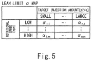
- the controller may determine the lean limit by using a lean limit map in which lean limit values are defined in association with the target injection amount and a rotational speed of the gas engine.
- the above gas engine drive system may further include an open passage for releasing air in the intake passage into an atmosphere, the open passage being provided with an open/close valve.
- the controller may: when the required output increases during a time in which the fuel injection amount is kept to zero, re-determine the lean limit of the charge air pressure based on the target injection amount corresponding to the required output that has increased; if the charge air pressure detected by the pressure detector is lower than or equal to the re-determined lean limit, increase the fuel injection amount to the target injection amount; and if the charge air pressure detected by the pressure detector is higher than the re-determined lean limit, open the open/close valve.
- the open/close valve is opened, the charge air pressure can be lowered immediately. This consequently makes it possible to improve the responsiveness of the gas engine to the increase in the required output.
- the controller may close the open/close valve, and increase the fuel injection amount to the target injection amount.
- the present invention also provides a method of controlling a gas engine equipped with a turbocharger.
- the method includes: when a required output decreases, determining a lean limit of a charge air pressure that is a pressure of intake air supplied from the turbocharger to the gas engine; if the charge air pressure is lower than or equal to the lean limit, decreasing a fuel injection amount to a target injection amount corresponding to the required output that has decreased; and if the charge air pressure is higher than the lean limit, bringing the fuel injection amount to zero, and then when the charge air pressure becomes lower than or equal to the lean limit, increasing the fuel injection amount to the target injection amount.
- This method similar to the above gas engine drive system, makes it possible to decrease the fuel gas when the required output decreases while preventing misfire and suppressing the discharge of the uncombusted fuel gas.
- the above method of controlling the gas engine may include: when the required output increases during a time in which the fuel injection amount is kept to zero, re-determining the lean limit of the charge air pressure; if the charge air pressure is lower than or equal to the re-determined lean limit, increasing the fuel injection amount to a target injection amount corresponding to the required output that has increased; and if the charge air pressure is higher than the re-determined lean limit, releasing air that is to be supplied from the turbocharger to the gas engine into an atmosphere.
- the above gas engine may be used as a main engine of a ship.
- the present invention makes it possible to decrease the fuel gas when the required output decreases while preventing misfire and suppressing the discharge of the uncombusted fuel gas.
- Fig. 1A shows a ship 11, in which a gas engine drive system 1 according to Embodiment 1 of the present invention (hereinafter, simply referred to as "system 1") is installed.
- the system 1 includes a gas engine 2, a turbocharger 3, and a controller 7 (see Fig. 2 ).
- a propeller shaft 13 mounted with a propeller 12 is directly driven by the gas engine 2 of the system 1.
- the propeller shaft 13 may be indirectly driven by the gas engine 2 via a motor 14 and a power generator 15 as shown in Fig. 1B .
- the gas engine 2 is used as a main engine of the ship 11.
- the gas engine 2 is, for example, a pure gas engine that combusts only a fuel gas (e.g., natural gas).
- the gas engine 2 may be a dual fuel engine that combusts one of or both a fuel gas and a fuel oil depending on the situation.
- the gas engine 2 is a 4-stroke engine in the present embodiment, the gas engine 2 may be a 2-stroke engine.
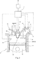
- Fig. 2 is a sectional view showing an essential part of the gas engine 2.
- the gas engine 2 includes a plurality of cylinders 21 ( Fig. 2 shows only one cylinder 21).
- a piston 22 is disposed such that the piston 22 is movable in a reciprocating manner.
- the cylinder 21 and the piston 22 form a combustion chamber 20.
- the piston 22 is coupled to an unshown crank shaft by an unshown connecting rod.
- the piston 22 reciprocates twice, and thereby one cycle of the gas engine 2 (intake, compression, expansion, and exhaust) is performed.
- the phase angle (0 to 720 degrees) of the gas engine 2 during one cycle of each cylinder 21 is detected by a phase angle detector 63.
- the rotation angle of the crank shaft i.e., crank angle
- the position of the piston 22 can be used as the phase angle.
- the phase angle detector 63 is an electromagnetic pickup, a proximity switch, or a rotary encoder.
- An actual rotational speed N of the gas engine 2 is also detected from the phase angle detector 63.
- Each combustion chamber 20 is connected to a compressor 31 of the turbocharger 3 via an intake passage 41, and also connected to a turbine 32 of the turbocharger 3 via an exhaust passage 42. That is, the intake passage 41 leads air compressed by the compressor 31 to each combustion chamber 20 as intake air, and the exhaust passage 42 leads combustion exhaust gas from each combustion chamber 20 to the turbine 32. It should be noted that, in reality, each of the downstream portion of the intake passage 41 and the upstream portion of the exhaust passage 42 branches off from a corresponding manifold into the same number of branch passages as the number of cylinders 21. However, in Figs. 1A and 1B , each of the intake passage 41 and the exhaust passage 42 is drawn as a single passage for the sake of simplifying the drawings.
- the intake passage 41 is provided with a radiator 43 for cooling the intake air supplied from the compressor 31 to each combustion chamber 20.
- the intake passage 41 is also provided with: a first pressure sensor 61 (corresponding to a pressure detector of the present invention), which detects a charge air pressure that is the pressure of the intake air; and a temperature sensor 65 (corresponding to a temperature detector of the present invention), which detects a charge air temperature that is the temperature of the intake air.
- the intake passage 41 is further provided with, for each cylinder 21, a main fuel injection valve 51 (corresponding to a fuel injection system of the present invention), which injects a fuel gas into the intake air.
- the fuel injection system of the present invention need not be the fuel injection valve 51, so long as the fuel injection system injects the fuel gas into the intake air.
- the fuel injection system may be configured to include: a fuel gas supply passage that merges with an air supply passage connected to the suction port of the compressor 31; and a fuel flow control valve provided on the fuel gas supply passage, and configured to inject the fuel gas into air sucked into the compressor 31.
- Each cylinder 21 is provided with: an intake valve 23, which opens and closes an intake port that is an opening of the intake passage 41, the opening facing the combustion chamber 20; and an exhaust valve 24, which opens and closes an exhaust port that is an opening of the exhaust passage 42, the opening facing the combustion chamber 20.
- Each cylinder 21 is also provided with a spark plug (an ignition system) 55 for igniting an air-fuel mixture of air and the fuel gas in the combustion chamber 20.
- the combustion chamber 20 includes: a main combustion chamber 20A, which communicates with the intake passage 41 and the exhaust passage 42; and an auxiliary combustion chamber 20B, which is divided from the main combustion chamber 20A by a dividing wall 25 with communication holes formed therein.
- the spark plug 55 is disposed in the auxiliary combustion chamber 20B.
- the fuel gas is injected from an auxiliary fuel injection valve 52 into the auxiliary combustion chamber 20B.
- a rich air-fuel mixture is formed in the auxiliary combustion chamber 20B by the injection of the fuel gas from the auxiliary fuel injection valve 52, and the air-fuel mixture is ignited by the spark plug 55.
- the main combustion chamber 20A is provided with a second pressure sensor 62, which detects an in-cylinder pressure, which is the pressure in the main combustion chamber 20A.
- a pilot fuel injection valve that directly injects a high-pressure pilot fuel (oil or fuel gas) into the main combustion chamber 20A to cause self-ignition of the pilot fuel can be adopted as the ignition system.
- the combustion exhaust gas from the combustion chamber 20 is fed through the exhaust passage 42 to the turbine 32, in which the combustion exhaust gas is used as motive force for driving the compressor 31.
- the system 1 of the present embodiment further includes an open passage 8 for releasing the air in the intake passage 41 into the atmosphere.
- One end of the open passage 8 is connected to the intake passage 41 at a position downstream of the radiator 43, and the other end of the open passage 8 is open to the atmosphere.
- the open passage 8 is provided with a blow-off valve 81, which is an open/close valve. It should be noted that the one end of the open passage 8 may be connected to the intake passage 41 at a position upstream of the radiator 43.
- the controller 7 calculates a target injection amount of the fuel gas to be injected from the main fuel injection valve 51 in accordance with a required output, and controls the fuel injection valves 51 and 52 and the spark plug 55 based on the phase angle detected by the phase angle detector 63. Specifically, during a time in which the required output hardly varies, the controller 7 performs a steady operation, and when the required output decreases during the steady operation, the controller 7 shifts to a fuel decrease operation. In both the steady operation and the fuel decrease operation, the controller 7 also performs control to keep the actual rotational speed N to a target rotational speed NT.
- Factors that cause decrease in the required output include: a command from an operator of the ship to lower the navigation speed of the ship; a command to keep the navigation speed when winds and waves that the hull is subjected to have become weaker; and decrease in the propeller pitch of the propeller 12 in a case where the propeller 12 is a variable pitch propeller.
- the steady operation is the operation in which the fuel injection amount is substantially constant regardless of whether the load of the gas engine 2 is high or low.
- the knocking control operation is the operation of optimizing the ignition timing while keeping the excess air ratio constant in order to achieve high efficiency.
- control is performed based on the in-cylinder pressure detected by the second pressure sensor 62. It should be noted that a control method used in the knocking control operation is described in detail by Patent Literature 1.
- the controller 7 shifts to the fuel decrease operation.
- the fuel decrease operation is described in detail. It should be noted that the description of control is given below for only one cylinder 21 as a representative example. The same control is performed for all the cylinders 21.
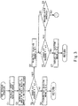
- Fig. 3 and Fig. 4 is a flowchart of the fuel decrease operation.
- the controller 7 calculates a target injection amount Q corresponding to the required output that has decreased (step S1). Then, the controller 7 determines a lean limit ⁇ of the charge air pressure based on the calculated target injection amount Q and the actual rotational speed N of the gas engine 2 (step S2).
- the lean limit is the upper limit value of the charge air pressure for preventing misfire.
- the lean limit is derived in advance through an experiment or numerical simulation. In the present embodiment, the lean limit ⁇ is determined by using a lean limit ⁇ map shown in Fig.
- the lean limit ⁇ thus determined is corrected based on the charge air temperature detected by the temperature sensor 65. For example, when the temperature of the intake air is relatively high, the lean limit ⁇ is corrected to be higher, and when the temperature of the intake air is relatively low, the lean limit ⁇ is corrected to be lower.
- a three-dimensional map in which the lean limit values are defined in association with the target injection amount of the fuel gas, the rotational speed of the gas engine 2, and the temperature of the intake air may be used.
- the controller 7 compares the charge air pressure P detected by the first pressure sensor 61 with the lean limit ⁇ (step S3). If the charge air pressure P is lower than or equal to the lean limit ⁇ (NO in step S3), the controller 7 decreases a fuel injection amount q from the main fuel injection valve 51 directly to the target injection amount Q (step S4), and returns to the steady operation. This is a normal decrease mode.
- Fig. 6 shows temporal changes in the required output, the charge air pressure P, and the fuel injection amount q in the normal decrease mode. In a case where the degree of decrease in the required output is relatively small, processing is performed in the normal decrease mode.
- Fig. 7 shows temporal changes in the required output, the charge air pressure P, and the fuel injection amount q in the transitional decrease mode.
- step S5 if the charge air pressure P detected by the first pressure sensor 61 is higher than the lean limit ⁇ determined in step S2 (YES in step S3), the controller 7 brings the fuel injection amount q to zero (step S5). In other words, the fuel is cut off. Of course, during a time in which the fuel injection amount q from the main fuel injection valve 51 is kept to zero, the fuel injection amount from the auxiliary fuel injection valve 52 is also kept to zero. Thereafter, until the charge air pressure P detected by the first pressure sensor 61 becomes lower than or equal to the lean limit ⁇ , the controller 7 keeps the fuel injection amount q to zero (YES in step S6). When the charge air pressure P becomes lower than or equal to the lean limit ⁇ (NO in step S6), the controller 7 increases the fuel injection amount q to the target injection amount Q (step S7), and returns to the steady operation. This is the transitional decrease mode.
- step S8 determines whether or not the required output has increased. In other words, so long as the required output does not increase (NO in step S8), the comparison in step S6 is repeated.
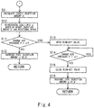
- the controller 7 performs processing in a re-determining mode shown in Fig. 4 .
- Fig. 8 shows temporal changes in the required output, the charge air pressure P, and the fuel injection amount q in the re-determining mode.
- the controller 7 calculates a target injection amount Q' corresponding to the required output that has increased (step S9). Then, the controller 7 re-determines the lean limit ⁇ of the charge air pressure based on the calculated target injection amount Q' and the current rotational speed of the gas engine 2 by using the lean limit ⁇ map shown in Fig. 5 again (step S10).
- the controller 7 compares the charge air pressure P detected by the first pressure sensor 61 with the re-determined lean limit ⁇ (step S11). If the charge air pressure P is lower than or equal to the lean limit ⁇ (NO in step S11), the controller 7 increases the fuel injection amount q from the main fuel injection valve 51 from 0 to the target injection amount Q' (step S12), and returns to the steady operation.
- step S11 if the charge air pressure P detected by the first pressure sensor 61 is higher than the re-determined lean limit ⁇ (YES in step S11), the controller 7 opens the blow-off valve 81 (step S13). Consequently, the charge air pressure P decreases immediately. Then, when the charge air pressure P detected by the first pressure sensor 61 becomes lower than or equal to the re-determined lean limit ⁇ (NO in step S14), the controller 7 closes the blow-off valve 81 (step S15), increases the fuel injection amount q from 0 to the target injection amount Q' (step S16), and returns to the steady operation.
- blow-off valve 81 If the blow-off valve 81 is not opened, then as indicated by a two-dot chain line in Fig. 8 , it may take some time for the charge air pressure P to become lower than or equal to the lean limit ⁇ after the required output increases. On the other hand, if the blow-off valve 81 is opened, the charge air pressure P can be lowered immediately, and thereby the timing at which the fuel gas can be injected without causing misfire can be made earlier as indicated by an arrow A in Fig. 8 . This consequently makes it possible to improve the responsiveness of the gas engine 2 to the increase in the required output.
- the fuel gas when the required output decreases, the fuel gas is not injected if the charge air pressure P is higher than the lean limit ⁇ . This makes it possible to prevent misfire and suppress the discharge of the uncombusted fuel gas. If the charge air pressure P is lower than or equal to the lean limit ⁇ when the required output decreases, or if the charge air pressure P becomes lower than or equal to the lean limit ⁇ during the time in which the fuel injection amount q is kept to zero, then the fuel injection amount q is set to the target injection amount Q. This makes it possible to shift the fuel injection amount q to the target injection amount Q at an optimal timing.
- the gas engine drive system of the present invention is not necessarily used in a ship, but may be used in, for example, power generating equipment, construction machines, or railways.
Landscapes
- Engineering & Computer Science (AREA)
- Chemical & Material Sciences (AREA)
- Combustion & Propulsion (AREA)
- Mechanical Engineering (AREA)
- General Engineering & Computer Science (AREA)
- Electrical Control Of Air Or Fuel Supplied To Internal-Combustion Engine (AREA)
- Output Control And Ontrol Of Special Type Engine (AREA)
- Supercharger (AREA)
Abstract
Description
- The present invention relates to a gas engine drive system including a turbocharger and a gas engine. The present invention also relates to a method of controlling a gas engine equipped with a turbocharger.
- Conventionally, gas engines that combust a fuel gas, such as natural gas or town gas, have been mainly used in power generating equipment (see
Patent Literature 1, for example). In recent years, in view of various issues such as the crude oil resource amount and exhaust gas regulations, it has been proposed to use a gas engine as a main engine of a ship instead of a diesel engine that uses heavy oil as a fuel. - For example,
Patent Literature 2 discloses a gas engine drive system in which a 4-stroke gas engine is combined with a turbocharger. One of the applications intended byPatent Literature 2 is the installation of the gas engine drive system in a ship. The gas engine includes a combustion chamber formed by a cylinder and a piston. The turbocharger includes: a compressor connected to the combustion chamber via an intake passage; and a turbine connected to the combustion chamber via an exhaust passage. The intake passage is provided with a throttle valve, and a mixer that mixes air with a fuel gas supplied from a fuel flow control valve is provided upstream of the compressor. - In the system disclosed by
Patent Literature 2, in order to improve load responsiveness while keeping highly precise air-fuel ratio (excess air ratio) control, when a change occurs in a speed command value signal that is a target value of the engine rotational speed, the fuel gas flow rate and the degree of opening of the throttle valve are changed. In particular,Patent Literature 2 describes in relation to the fuel gas flow rate that the upper limit value of the fuel gas flow rate may be determined based on the lower limit value of the excess air ratio in order to prevent misfire and abnormal combustion. -
- PTL 1: Japanese Laid-Open Patent Application Publication No.
2010-84681 - PTL 2: Japanese Laid-Open Patent Application Publication No.
2009-57870 - It is generally known that, in a gas engine, as shown in
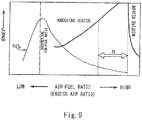
Fig. 9 , there exist a knocking region and a misfire region based on the relationship between the air-fuel ratio and the brake mean effective pressure (BMEP). Therefore, in order to obtain high power, it is important to control the air-fuel ratio to be between the knocking region and the misfire region as indicated by an arrow R inFig. 9 (so-called lean burn). -
Patent Literature 2 describes that the upper limit value of the fuel gas flow rate may be determined based on the lower limit value of the excess air ratio. This seems to be intended for a time when the required output increases. On the other hand, when the required output decreases, it is necessary to decrease the fuel gas. When the fuel gas is to be decreased, the amount of air introduced into the combustion chamber also needs to be decreased, otherwise the operating point in the range R shown inFig. 9 may move to the right into the misfire region. When misfire occurs, the fuel gas that is uncombusted is discharged from the gas engine. - However, in a gas engine equipped with a turbocharger, even when the fuel gas is decreased, the amount of air discharged from the compressor does not decrease immediately due to the inertia of the turbocharger. Therefore, in a case where no throttle valve is provided on the intake passage between the compressor and the combustion chamber, how to decrease the fuel gas while preventing misfire is a technical problem.
- In view of the above, an object of the present invention is to provide a gas engine drive system and a method of controlling a gas engine, the system and the method making it possible to decrease the fuel gas when the required output decreases while preventing misfire and suppressing the discharge of the uncombusted fuel gas even if no throttle valve is provided on the intake passage.
- In order to solve the above-described problems, a gas engine drive system according to the present invention includes: a gas engine including a combustion chamber formed by a cylinder and a piston; a turbocharger including a compressor connected to the combustion chamber via an intake passage and a turbine connected to the combustion chamber via an exhaust passage; a fuel injection system that injects a fuel gas into intake air that is supplied from the compressor to the combustion chamber via the intake passage; a pressure detector that detects a charge air pressure that is a pressure of the intake air; a temperature detector that detects a temperature of the intake air; and a controller that controls the fuel injection system, the controller calculating a target injection amount of the fuel gas in accordance with a required output. The controller: when the required output decreases, determines a lean limit of the charge air pressure based on the target injection amount corresponding to the required output that has decreased; if the charge air pressure detected by the pressure detector is lower than or equal to the lean limit, decreases a fuel injection amount to the target injection amount; and if the charge air pressure detected by the pressure detector is higher than the lean limit, brings the fuel injection amount to zero, and then when the charge air pressure detected by the pressure detector becomes lower than or equal to the lean limit, increases the fuel injection amount to the target injection amount.
- According to the above configuration, when the required output decreases, the fuel gas is not injected if the charge air pressure is higher than the lean limit. This makes it possible to prevent misfire and suppress the discharge of the uncombusted fuel gas. If the charge air pressure is lower than or equal to the lean limit when the required output decreases, or if the charge air pressure becomes lower than or equal to the lean limit during the time in which the fuel injection amount is kept to zero, then the fuel injection amount is set to the target injection amount. This makes it possible to shift the fuel injection amount to the target injection amount at an optimal timing.
- For example, the above gas engine drive system may further include a temperature detector that detects a temperature of the intake air. After determining the lean limit of the charge air pressure, the controller may correct the lean limit of the charge air pressure based on the temperature of the intake air detected by the temperature detector.
- The controller may determine the lean limit by using a lean limit map in which lean limit values are defined in association with the target injection amount and a rotational speed of the gas engine.
- The above gas engine drive system may further include an open passage for releasing air in the intake passage into an atmosphere, the open passage being provided with an open/close valve. The controller may: when the required output increases during a time in which the fuel injection amount is kept to zero, re-determine the lean limit of the charge air pressure based on the target injection amount corresponding to the required output that has increased; if the charge air pressure detected by the pressure detector is lower than or equal to the re-determined lean limit, increase the fuel injection amount to the target injection amount; and if the charge air pressure detected by the pressure detector is higher than the re-determined lean limit, open the open/close valve. According to this configuration, when the open/close valve is opened, the charge air pressure can be lowered immediately. This consequently makes it possible to improve the responsiveness of the gas engine to the increase in the required output.
- After opening the open/close valve, when the charge air pressure detected by the pressure detector becomes lower than or equal to the re-determined lean limit, the controller may close the open/close valve, and increase the fuel injection amount to the target injection amount.
- The present invention also provides a method of controlling a gas engine equipped with a turbocharger. The method includes: when a required output decreases, determining a lean limit of a charge air pressure that is a pressure of intake air supplied from the turbocharger to the gas engine; if the charge air pressure is lower than or equal to the lean limit, decreasing a fuel injection amount to a target injection amount corresponding to the required output that has decreased; and if the charge air pressure is higher than the lean limit, bringing the fuel injection amount to zero, and then when the charge air pressure becomes lower than or equal to the lean limit, increasing the fuel injection amount to the target injection amount. This method, similar to the above gas engine drive system, makes it possible to decrease the fuel gas when the required output decreases while preventing misfire and suppressing the discharge of the uncombusted fuel gas.
- The above method of controlling the gas engine may include: when the required output increases during a time in which the fuel injection amount is kept to zero, re-determining the lean limit of the charge air pressure; if the charge air pressure is lower than or equal to the re-determined lean limit, increasing the fuel injection amount to a target injection amount corresponding to the required output that has increased; and if the charge air pressure is higher than the re-determined lean limit, releasing air that is to be supplied from the turbocharger to the gas engine into an atmosphere.
- For example, the above gas engine may be used as a main engine of a ship.
- The present invention makes it possible to decrease the fuel gas when the required output decreases while preventing misfire and suppressing the discharge of the uncombusted fuel gas.
-
-
Fig. 1A shows a schematic configuration of a ship in which a gas engine drive system according to one embodiment of the present invention is installed, andFig. 1B shows a schematic configuration of the ship according to one variation. -
Fig 2 is a sectional view showing one combustion chamber and its vicinity of a gas engine. -
Fig. 3 is a flowchart of a fuel decrease operation. -
Fig. 4 is a flowchart of the fuel decrease operation. -
Fig. 5 is a lean limit map in which lean limit values are defined in association with a target injection amount of a fuel gas and a rotational speed of the gas engine. -
Fig. 6 is a graph showing temporal changes in a required output, a charge air pressure P, and a fuel injection amount q when the fuel injection amount q is decreased directly to a target injection amount Q. -
Fig. 7 is a graph showing temporal changes in the required output, the charge air pressure P, and the fuel injection amount q when the fuel injection amount q is increased to the target injection amount Q after bringing the fuel injection amount q to zero. -
Fig. 8 is a graph showing temporal changes in the required output, the charge air pressure P, and the fuel injection amount q when the required output increases during a time in which the fuel injection amount is kept to zero. -
Fig. 9 is a graph showing a knocking region and a misfire region of a gas engine, the graph having a horizontal axis that represents air-fuel ratio and a vertical axis that represents brake mean effective pressure. -
Fig. 1A shows aship 11, in which a gasengine drive system 1 according toEmbodiment 1 of the present invention (hereinafter, simply referred to as "system 1") is installed. Thesystem 1 includes agas engine 2, aturbocharger 3, and a controller 7 (seeFig. 2 ). In the present embodiment, apropeller shaft 13 mounted with apropeller 12 is directly driven by thegas engine 2 of thesystem 1. However, as an alternative, thepropeller shaft 13 may be indirectly driven by thegas engine 2 via amotor 14 and apower generator 15 as shown inFig. 1B . In both the case shown inFig. 1A and the case shown inFig. 1B , thegas engine 2 is used as a main engine of theship 11. - The
gas engine 2 is, for example, a pure gas engine that combusts only a fuel gas (e.g., natural gas). Alternatively, thegas engine 2 may be a dual fuel engine that combusts one of or both a fuel gas and a fuel oil depending on the situation. Although thegas engine 2 is a 4-stroke engine in the present embodiment, thegas engine 2 may be a 2-stroke engine. -
Fig. 2 is a sectional view showing an essential part of thegas engine 2. Thegas engine 2 includes a plurality of cylinders 21 (Fig. 2 shows only one cylinder 21). In eachcylinder 21, apiston 22 is disposed such that thepiston 22 is movable in a reciprocating manner. Thecylinder 21 and thepiston 22 form acombustion chamber 20. Thepiston 22 is coupled to an unshown crank shaft by an unshown connecting rod. - In each
cylinder 21, thepiston 22 reciprocates twice, and thereby one cycle of the gas engine 2 (intake, compression, expansion, and exhaust) is performed. The phase angle (0 to 720 degrees) of thegas engine 2 during one cycle of eachcylinder 21 is detected by aphase angle detector 63. For example, the rotation angle of the crank shaft (i.e., crank angle) or the position of thepiston 22 can be used as the phase angle. As one example, thephase angle detector 63 is an electromagnetic pickup, a proximity switch, or a rotary encoder. An actual rotational speed N of thegas engine 2 is also detected from thephase angle detector 63. - Each
combustion chamber 20 is connected to acompressor 31 of theturbocharger 3 via anintake passage 41, and also connected to aturbine 32 of theturbocharger 3 via anexhaust passage 42. That is, theintake passage 41 leads air compressed by thecompressor 31 to eachcombustion chamber 20 as intake air, and theexhaust passage 42 leads combustion exhaust gas from eachcombustion chamber 20 to theturbine 32. It should be noted that, in reality, each of the downstream portion of theintake passage 41 and the upstream portion of theexhaust passage 42 branches off from a corresponding manifold into the same number of branch passages as the number ofcylinders 21. However, inFigs. 1A and 1B , each of theintake passage 41 and theexhaust passage 42 is drawn as a single passage for the sake of simplifying the drawings. - The
intake passage 41 is provided with aradiator 43 for cooling the intake air supplied from thecompressor 31 to eachcombustion chamber 20. Theintake passage 41 is also provided with: a first pressure sensor 61 (corresponding to a pressure detector of the present invention), which detects a charge air pressure that is the pressure of the intake air; and a temperature sensor 65 (corresponding to a temperature detector of the present invention), which detects a charge air temperature that is the temperature of the intake air. Theintake passage 41 is further provided with, for eachcylinder 21, a main fuel injection valve 51 (corresponding to a fuel injection system of the present invention), which injects a fuel gas into the intake air. - It should be noted that the fuel injection system of the present invention need not be the
fuel injection valve 51, so long as the fuel injection system injects the fuel gas into the intake air. For example, similar toPatent Literature 2, the fuel injection system may be configured to include: a fuel gas supply passage that merges with an air supply passage connected to the suction port of thecompressor 31; and a fuel flow control valve provided on the fuel gas supply passage, and configured to inject the fuel gas into air sucked into thecompressor 31. - Each
cylinder 21 is provided with: anintake valve 23, which opens and closes an intake port that is an opening of theintake passage 41, the opening facing thecombustion chamber 20; and anexhaust valve 24, which opens and closes an exhaust port that is an opening of theexhaust passage 42, the opening facing thecombustion chamber 20. Eachcylinder 21 is also provided with a spark plug (an ignition system) 55 for igniting an air-fuel mixture of air and the fuel gas in thecombustion chamber 20. - In the present embodiment, the
combustion chamber 20 includes: amain combustion chamber 20A, which communicates with theintake passage 41 and theexhaust passage 42; and anauxiliary combustion chamber 20B, which is divided from themain combustion chamber 20A by a dividingwall 25 with communication holes formed therein. Thespark plug 55 is disposed in theauxiliary combustion chamber 20B. The fuel gas is injected from an auxiliaryfuel injection valve 52 into theauxiliary combustion chamber 20B. A rich air-fuel mixture is formed in theauxiliary combustion chamber 20B by the injection of the fuel gas from the auxiliaryfuel injection valve 52, and the air-fuel mixture is ignited by thespark plug 55. As a result, a flame is generated in theauxiliary combustion chamber 20B, and the flame propagates into themain combustion chamber 20A through the communication holes formed in the dividingwall 25. Consequently, a lean air-fuel mixture in themain combustion chamber 20A is also ignited. Themain combustion chamber 20A is provided with asecond pressure sensor 62, which detects an in-cylinder pressure, which is the pressure in themain combustion chamber 20A. - It should be noted that instead of the
spark plug 55, which ignites the air-fuel mixture in theauxiliary combustion chamber 20B, a pilot fuel injection valve that directly injects a high-pressure pilot fuel (oil or fuel gas) into themain combustion chamber 20A to cause self-ignition of the pilot fuel can be adopted as the ignition system. - The combustion exhaust gas from the
combustion chamber 20 is fed through theexhaust passage 42 to theturbine 32, in which the combustion exhaust gas is used as motive force for driving thecompressor 31. - The
system 1 of the present embodiment further includes anopen passage 8 for releasing the air in theintake passage 41 into the atmosphere. One end of theopen passage 8 is connected to theintake passage 41 at a position downstream of theradiator 43, and the other end of theopen passage 8 is open to the atmosphere. Theopen passage 8 is provided with a blow-offvalve 81, which is an open/close valve. It should be noted that the one end of theopen passage 8 may be connected to theintake passage 41 at a position upstream of theradiator 43. - The
controller 7 calculates a target injection amount of the fuel gas to be injected from the mainfuel injection valve 51 in accordance with a required output, and controls thefuel injection valves spark plug 55 based on the phase angle detected by thephase angle detector 63. Specifically, during a time in which the required output hardly varies, thecontroller 7 performs a steady operation, and when the required output decreases during the steady operation, thecontroller 7 shifts to a fuel decrease operation. In both the steady operation and the fuel decrease operation, thecontroller 7 also performs control to keep the actual rotational speed N to a target rotational speed NT. Factors that cause decrease in the required output include: a command from an operator of the ship to lower the navigation speed of the ship; a command to keep the navigation speed when winds and waves that the hull is subjected to have become weaker; and decrease in the propeller pitch of thepropeller 12 in a case where thepropeller 12 is a variable pitch propeller. - The steady operation is the operation in which the fuel injection amount is substantially constant regardless of whether the load of the
gas engine 2 is high or low. As the steady operation, it is desirable to perform a knocking control operation as described inPatent Literature 1. The knocking control operation is the operation of optimizing the ignition timing while keeping the excess air ratio constant in order to achieve high efficiency. In the knocking control operation, control is performed based on the in-cylinder pressure detected by thesecond pressure sensor 62. It should be noted that a control method used in the knocking control operation is described in detail byPatent Literature 1. - As mentioned above, when the required output decreases during the steady operation, the
controller 7 shifts to the fuel decrease operation. Hereinafter, the fuel decrease operation is described in detail. It should be noted that the description of control is given below for only onecylinder 21 as a representative example. The same control is performed for all thecylinders 21. - In the fuel decrease operation, control is performed based on the charge air pressure P detected by the
first pressure sensor 61. Each ofFig. 3 andFig. 4 is a flowchart of the fuel decrease operation. - First, the
controller 7 calculates a target injection amount Q corresponding to the required output that has decreased (step S1). Then, thecontroller 7 determines a lean limit α of the charge air pressure based on the calculated target injection amount Q and the actual rotational speed N of the gas engine 2 (step S2). The lean limit is the upper limit value of the charge air pressure for preventing misfire. The lean limit is derived in advance through an experiment or numerical simulation. In the present embodiment, the lean limit α is determined by using a lean limit α map shown inFig. 5 , in which lean limit values αi,j (1 ≤ i ≤ n, 1 ≤ j ≤ m) are defined in association with the target injection amount of the fuel gas and the rotational speed of thegas engine 2. It should be noted that, desirably, the lean limit α thus determined is corrected based on the charge air temperature detected by thetemperature sensor 65. For example, when the temperature of the intake air is relatively high, the lean limit α is corrected to be higher, and when the temperature of the intake air is relatively low, the lean limit α is corrected to be lower. Alternatively, instead of the map shown inFig. 5 , a three-dimensional map in which the lean limit values are defined in association with the target injection amount of the fuel gas, the rotational speed of thegas engine 2, and the temperature of the intake air may be used. - Thereafter, the
controller 7 compares the charge air pressure P detected by thefirst pressure sensor 61 with the lean limit α (step S3). If the charge air pressure P is lower than or equal to the lean limit α (NO in step S3), thecontroller 7 decreases a fuel injection amount q from the mainfuel injection valve 51 directly to the target injection amount Q (step S4), and returns to the steady operation. This is a normal decrease mode. -
Fig. 6 shows temporal changes in the required output, the charge air pressure P, and the fuel injection amount q in the normal decrease mode. In a case where the degree of decrease in the required output is relatively small, processing is performed in the normal decrease mode. - On the other hand, in a case where the degree of decrease in the required output is relatively great, processing is performed in a transitional decrease mode.
Fig. 7 shows temporal changes in the required output, the charge air pressure P, and the fuel injection amount q in the transitional decrease mode. - As a result of the comparison in step S3, if the charge air pressure P detected by the
first pressure sensor 61 is higher than the lean limit α determined in step S2 (YES in step S3), thecontroller 7 brings the fuel injection amount q to zero (step S5). In other words, the fuel is cut off. Of course, during a time in which the fuel injection amount q from the mainfuel injection valve 51 is kept to zero, the fuel injection amount from the auxiliaryfuel injection valve 52 is also kept to zero. Thereafter, until the charge air pressure P detected by thefirst pressure sensor 61 becomes lower than or equal to the lean limit α, thecontroller 7 keeps the fuel injection amount q to zero (YES in step S6). When the charge air pressure P becomes lower than or equal to the lean limit α (NO in step S6), thecontroller 7 increases the fuel injection amount q to the target injection amount Q (step S7), and returns to the steady operation. This is the transitional decrease mode. - During the time in which the fuel injection amount q is kept to zero, the
controller 7 further determines whether or not the required output has increased (step S8). In other words, so long as the required output does not increase (NO in step S8), the comparison in step S6 is repeated. When the required output increases during the time in which the fuel injection amount q is kept to zero (YES in step S8), thecontroller 7 performs processing in a re-determining mode shown inFig. 4 .Fig. 8 shows temporal changes in the required output, the charge air pressure P, and the fuel injection amount q in the re-determining mode. - First, the
controller 7 calculates a target injection amount Q' corresponding to the required output that has increased (step S9). Then, thecontroller 7 re-determines the lean limit α of the charge air pressure based on the calculated target injection amount Q' and the current rotational speed of thegas engine 2 by using the lean limit α map shown inFig. 5 again (step S10). - Thereafter, the
controller 7 compares the charge air pressure P detected by thefirst pressure sensor 61 with the re-determined lean limit α (step S11). If the charge air pressure P is lower than or equal to the lean limit α (NO in step S11), thecontroller 7 increases the fuel injection amount q from the mainfuel injection valve 51 from 0 to the target injection amount Q' (step S12), and returns to the steady operation. - On the other hand, as a result of the comparison in step S11, if the charge air pressure P detected by the
first pressure sensor 61 is higher than the re-determined lean limit α (YES in step S11), thecontroller 7 opens the blow-off valve 81 (step S13). Consequently, the charge air pressure P decreases immediately. Then, when the charge air pressure P detected by thefirst pressure sensor 61 becomes lower than or equal to the re-determined lean limit α (NO in step S14), thecontroller 7 closes the blow-off valve 81 (step S15), increases the fuel injection amount q from 0 to the target injection amount Q' (step S16), and returns to the steady operation. - If the blow-off
valve 81 is not opened, then as indicated by a two-dot chain line inFig. 8 , it may take some time for the charge air pressure P to become lower than or equal to the lean limit α after the required output increases. On the other hand, if the blow-offvalve 81 is opened, the charge air pressure P can be lowered immediately, and thereby the timing at which the fuel gas can be injected without causing misfire can be made earlier as indicated by an arrow A inFig. 8 . This consequently makes it possible to improve the responsiveness of thegas engine 2 to the increase in the required output. - As described above, in the gas
engine drive system 1 of the present embodiment, when the required output decreases, the fuel gas is not injected if the charge air pressure P is higher than the lean limit α. This makes it possible to prevent misfire and suppress the discharge of the uncombusted fuel gas. If the charge air pressure P is lower than or equal to the lean limit α when the required output decreases, or if the charge air pressure P becomes lower than or equal to the lean limit α during the time in which the fuel injection amount q is kept to zero, then the fuel injection amount q is set to the target injection amount Q. This makes it possible to shift the fuel injection amount q to the target injection amount Q at an optimal timing. - The present invention is not limited to the above-described embodiment. Various modifications can be made without departing from the spirit of the present invention. For example, the
open passage 8 may be eliminated. - The gas engine drive system of the present invention is not necessarily used in a ship, but may be used in, for example, power generating equipment, construction machines, or railways.
-
- 1 gas engine drive system
- 11 ship
- 2 gas engine
- 20 combustion chamber
- 21 cylinder
- 22 piston
- 3 turbocharger
- 31 compressor
- 32 turbine
- 41 intake passage
- 42 exhaust passage
- 51 main fuel injection valve (fuel injection system)
- 52 auxiliary fuel injection valve
- 61 first pressure sensor (pressure detector)
- 62 second pressure sensor
- 65 temperature sensor (temperature detector)
- 7 controller
- 8 open passage
- 81 blow-off valve (open/close valve)
Claims (8)
- A gas engine drive system comprising:a gas engine including a combustion chamber formed by a cylinder and a piston;a turbocharger including a compressor connected to the combustion chamber via an intake passage and a turbine connected to the combustion chamber via an exhaust passage;a fuel injection system that injects a fuel gas into intake air that is supplied from the compressor to the combustion chamber via the intake passage;a pressure detector that detects a charge air pressure that is a pressure of the intake air; anda controller that controls the fuel injection system, the controller calculating a target injection amount of the fuel gas in accordance with a required output, whereinthe controller:when the required output decreases, determines a lean limit of the charge air pressure based on the target injection amount corresponding to the required output that has decreased;if the charge air pressure detected by the pressure detector is lower than or equal to the lean limit, decreases a fuel injection amount to the target injection amount; andif the charge air pressure detected by the pressure detector is higher than the lean limit, brings the fuel injection amount to zero, and then when the charge air pressure detected by the pressure detector becomes lower than or equal to the lean limit, increases the fuel injection amount to the target injection amount.
- The gas engine drive system according to claim 1, further comprising a temperature detector that detects a temperature of the intake air, wherein
after determining the lean limit of the charge air pressure, the controller corrects the lean limit of the charge air pressure based on the temperature of the intake air detected by the temperature detector. - The gas engine drive system according to claim 1 or 2, wherein
the controller determines the lean limit by using a lean limit map in which lean limit values are defined in association with the target injection amount and a rotational speed of the gas engine. - The gas engine drive system according to any one of claims 1 to 3, further comprising an open passage for releasing air in the intake passage into an atmosphere, the open passage being provided with an open/close valve, wherein
the controller:when the required output increases during a time in which the fuel injection amount is kept to zero, re-determines the lean limit of the charge air pressure based on the target injection amount corresponding to the required output that has increased;if the charge air pressure detected by the pressure detector is lower than or equal to the re-determined lean limit, increases the fuel injection amount to the target injection amount; andif the charge air pressure detected by the pressure detector is higher than the re-determined lean limit, opens the open/close valve. - The gas engine drive system according to claim 4, wherein
after opening the open/close valve, when the charge air pressure detected by the pressure detector becomes lower than or equal to the re-determined lean limit, the controller closes the open/close valve, and increases the fuel injection amount to the target injection amount. - A method of controlling a gas engine equipped with a turbocharger, the method comprising:when a required output decreases, determining a lean limit of a charge air pressure that is a pressure of intake air supplied from the turbocharger to the gas engine;if the charge air pressure is lower than or equal to the lean limit, decreasing a fuel injection amount to a target injection amount corresponding to the required output that has decreased; andif the charge air pressure is higher than the lean limit, bringing the fuel injection amount to zero, and then when the charge air pressure becomes lower than or equal to the lean limit, increasing the fuel injection amount to the target injection amount.
- The method of controlling the gas engine according to claim 6, comprising:when the required output increases during a time in which the fuel injection amount is kept to zero, re-determining the lean limit of the charge air pressure;if the charge air pressure is lower than or equal to the re-determined lean limit, increasing the fuel injection amount to a target injection amount corresponding to the required output that has increased; andif the charge air pressure is higher than the re-determined lean limit, releasing air that is to be supplied from the turbocharger to the gas engine into an atmosphere.
- The method of controlling the gas engine according to claim 6 or 7, wherein
the gas engine is used as a main engine of a ship.
Applications Claiming Priority (2)
| Application Number | Priority Date | Filing Date | Title |
|---|---|---|---|
| JP2016016200A JP6002339B1 (en) | 2016-01-29 | 2016-01-29 | Gas engine drive system and gas engine control method |
| PCT/JP2016/082434 WO2017130502A1 (en) | 2016-01-29 | 2016-11-01 | Gas engine drive system and gas engine control method |
Publications (3)
| Publication Number | Publication Date |
|---|---|
| EP3409929A1 true EP3409929A1 (en) | 2018-12-05 |
| EP3409929A4 EP3409929A4 (en) | 2019-10-23 |
| EP3409929B1 EP3409929B1 (en) | 2021-01-06 |
Family
ID=57048636
Family Applications (1)
| Application Number | Title | Priority Date | Filing Date |
|---|---|---|---|
| EP16888087.0A Not-in-force EP3409929B1 (en) | 2016-01-29 | 2016-11-01 | Gas engine drive system and method of controlling gas engine |
Country Status (4)
| Country | Link |
|---|---|
| US (1) | US10844796B2 (en) |
| EP (1) | EP3409929B1 (en) |
| JP (1) | JP6002339B1 (en) |
| WO (1) | WO2017130502A1 (en) |
Families Citing this family (3)
| Publication number | Priority date | Publication date | Assignee | Title |
|---|---|---|---|---|
| US10837355B2 (en) * | 2017-12-28 | 2020-11-17 | Honda Motor Co., Ltd. | Internal combustion engine |
| US10760519B2 (en) * | 2018-05-22 | 2020-09-01 | Mazda Motor Corporation | Control device of compression-ignition engine |
| JP2025018644A (en) * | 2023-07-27 | 2025-02-06 | ヤンマーホールディングス株式会社 | ENGINE DEVICE AND CONTROL METHOD FOR ENGINE DEVICE |
Family Cites Families (15)
| Publication number | Priority date | Publication date | Assignee | Title |
|---|---|---|---|---|
| JPH05280407A (en) * | 1992-03-31 | 1993-10-26 | Mazda Motor Corp | Two-cycle engine controller |
| JPH05280358A (en) * | 1992-03-31 | 1993-10-26 | Mazda Motor Corp | Two-cycle engine controller |
| JPH06280642A (en) * | 1993-03-26 | 1994-10-04 | Mazda Motor Corp | Air-fuel ratio control device for engine |
| JP4176199B2 (en) * | 1998-08-31 | 2008-11-05 | 富士重工業株式会社 | Engine control device |
| JP2000192846A (en) * | 1998-12-25 | 2000-07-11 | Nissan Motor Co Ltd | Combustion control device for internal combustion engine |
| JP3743195B2 (en) * | 1999-02-26 | 2006-02-08 | ふそうエンジニアリング株式会社 | Premixed compression ignition internal combustion engine |
| JP4075395B2 (en) * | 2001-05-25 | 2008-04-16 | マツダ株式会社 | Control device for vehicle engine |
| JP4054547B2 (en) * | 2001-06-01 | 2008-02-27 | 株式会社日立製作所 | Control device for internal combustion engine |
| JP2003262139A (en) * | 2002-03-08 | 2003-09-19 | Mitsubishi Heavy Ind Ltd | Method and device for controlling air-fuel ratio of gas engine |
| JP4476317B2 (en) * | 2007-08-30 | 2010-06-09 | 三菱重工業株式会社 | Integrated control method and apparatus for gas engine |
| JP2009162140A (en) * | 2008-01-08 | 2009-07-23 | Honda Motor Co Ltd | Aircraft engine with electronic throttle |
| JP4772846B2 (en) | 2008-10-01 | 2011-09-14 | 川崎重工業株式会社 | Gas engine knocking control device |
| AT509558B1 (en) * | 2010-01-19 | 2012-09-15 | Ge Jenbacher Gmbh & Co Ohg | STATIONARY POWER PLANT |
| JP6002235B2 (en) * | 2012-10-05 | 2016-10-05 | 川崎重工業株式会社 | Combustion stabilization device for gas engines |
| JP6149748B2 (en) * | 2014-02-04 | 2017-06-21 | トヨタ自動車株式会社 | Vehicle control device |
-
2016
- 2016-01-29 JP JP2016016200A patent/JP6002339B1/en active Active
- 2016-11-01 EP EP16888087.0A patent/EP3409929B1/en not_active Not-in-force
- 2016-11-01 WO PCT/JP2016/082434 patent/WO2017130502A1/en not_active Ceased
- 2016-11-01 US US16/073,893 patent/US10844796B2/en not_active Expired - Fee Related
Also Published As
| Publication number | Publication date |
|---|---|
| JP6002339B1 (en) | 2016-10-05 |
| JP2017133477A (en) | 2017-08-03 |
| EP3409929B1 (en) | 2021-01-06 |
| WO2017130502A1 (en) | 2017-08-03 |
| US10844796B2 (en) | 2020-11-24 |
| US20190040807A1 (en) | 2019-02-07 |
| EP3409929A4 (en) | 2019-10-23 |
Similar Documents
| Publication | Publication Date | Title |
|---|---|---|
| US10480426B2 (en) | Method of controlling gas engine and gas engine drive system | |
| EP2518299B9 (en) | Device and method of controlling gas engine | |
| KR101842311B1 (en) | Method of operating an internal combustion piston engine in transient load change, a control system for controlling the operating of an internal combustion engine, and a piston engine | |
| EP2891780B1 (en) | Uniflow scavenging two-cycle engine | |
| EP1358399B1 (en) | A device and a method for controlling the fuel-air ratio | |
| JP2017057775A (en) | Engine device | |
| EP3409929B1 (en) | Gas engine drive system and method of controlling gas engine | |
| US20160252030A1 (en) | Auxiliary-chamber-type gas engine | |
| US10487727B2 (en) | Method of controlling gas engine | |
| JP7449350B2 (en) | Large 2-stroke uniflow scavenging gas fuel engine and liquid fuel supply control method | |
| JP4835279B2 (en) | Multi-fuel internal combustion engine | |
| KR20190055263A (en) | A method of operating an internal combustion piston engine, a control system for controlling the operation of an internal combustion piston engine, and an internal combustion piston engine | |
| CN111094726B (en) | Engine operating method and engine system | |
| EP4424981B1 (en) | Method for operating an internal combustion engine system using hydrogen fuel | |
| US20180355816A1 (en) | Dual-fuel internal combustion engine | |
| CN107743544A (en) | bi-fuel internal combustion engine | |
| JP2024120858A (en) | Large turbocharged two-stroke uniflow crosshead internal combustion engine and its operating method | |
| CN113811678A (en) | Transient controller and method for dual fuel engine | |
| JPS6318153A (en) | Fuel injection device for engine | |
| JP2016075166A (en) | Gas engine operation control method for gas engine and gas engine |
Legal Events
| Date | Code | Title | Description |
|---|---|---|---|
| STAA | Information on the status of an ep patent application or granted ep patent |
Free format text: STATUS: THE INTERNATIONAL PUBLICATION HAS BEEN MADE |
|
| PUAI | Public reference made under article 153(3) epc to a published international application that has entered the european phase |
Free format text: ORIGINAL CODE: 0009012 |
|
| STAA | Information on the status of an ep patent application or granted ep patent |
Free format text: STATUS: REQUEST FOR EXAMINATION WAS MADE |
|
| 17P | Request for examination filed |
Effective date: 20180827 |
|
| AK | Designated contracting states |
Kind code of ref document: A1 Designated state(s): AL AT BE BG CH CY CZ DE DK EE ES FI FR GB GR HR HU IE IS IT LI LT LU LV MC MK MT NL NO PL PT RO RS SE SI SK SM TR |
|
| AX | Request for extension of the european patent |
Extension state: BA ME |
|
| DAV | Request for validation of the european patent (deleted) | ||
| DAX | Request for extension of the european patent (deleted) | ||
| A4 | Supplementary search report drawn up and despatched |
Effective date: 20190919 |
|
| RIC1 | Information provided on ipc code assigned before grant |
Ipc: F02D 23/00 20060101AFI20190914BHEP Ipc: F02D 41/02 20060101ALI20190914BHEP Ipc: F02B 37/12 20060101ALI20190914BHEP Ipc: F02D 19/02 20060101ALI20190914BHEP Ipc: F02D 41/04 20060101ALI20190914BHEP Ipc: F02D 41/00 20060101ALI20190914BHEP Ipc: F02D 41/14 20060101ALI20190914BHEP Ipc: F02D 41/34 20060101ALI20190914BHEP Ipc: F02D 41/12 20060101ALI20190914BHEP |
|
| GRAP | Despatch of communication of intention to grant a patent |
Free format text: ORIGINAL CODE: EPIDOSNIGR1 |
|
| STAA | Information on the status of an ep patent application or granted ep patent |
Free format text: STATUS: GRANT OF PATENT IS INTENDED |
|
| RIC1 | Information provided on ipc code assigned before grant |
Ipc: F02D 41/12 20060101ALI20200612BHEP Ipc: F02D 41/00 20060101ALI20200612BHEP Ipc: F02D 41/34 20060101ALI20200612BHEP Ipc: F02D 23/00 20060101AFI20200612BHEP Ipc: F02B 37/12 20060101ALI20200612BHEP Ipc: F02D 19/02 20060101ALI20200612BHEP Ipc: F02D 41/14 20060101ALI20200612BHEP Ipc: F02D 41/02 20060101ALI20200612BHEP Ipc: F02D 41/04 20060101ALI20200612BHEP |
|
| INTG | Intention to grant announced |
Effective date: 20200706 |
|
| GRAS | Grant fee paid |
Free format text: ORIGINAL CODE: EPIDOSNIGR3 |
|
| GRAA | (expected) grant |
Free format text: ORIGINAL CODE: 0009210 |
|
| STAA | Information on the status of an ep patent application or granted ep patent |
Free format text: STATUS: THE PATENT HAS BEEN GRANTED |
|
| AK | Designated contracting states |
Kind code of ref document: B1 Designated state(s): AL AT BE BG CH CY CZ DE DK EE ES FI FR GB GR HR HU IE IS IT LI LT LU LV MC MK MT NL NO PL PT RO RS SE SI SK SM TR |
|
| REG | Reference to a national code |
Ref country code: GB Ref legal event code: FG4D |
|
| REG | Reference to a national code |
Ref country code: AT Ref legal event code: REF Ref document number: 1352621 Country of ref document: AT Kind code of ref document: T Effective date: 20210115 Ref country code: CH Ref legal event code: EP |
|
| REG | Reference to a national code |
Ref country code: DE Ref legal event code: R096 Ref document number: 602016051237 Country of ref document: DE |
|
| REG | Reference to a national code |
Ref country code: IE Ref legal event code: FG4D |
|
| REG | Reference to a national code |
Ref country code: FI Ref legal event code: FGE |
|
| REG | Reference to a national code |
Ref country code: NO Ref legal event code: T2 Effective date: 20210106 |
|
| REG | Reference to a national code |
Ref country code: NL Ref legal event code: MP Effective date: 20210106 |
|
| REG | Reference to a national code |
Ref country code: LT Ref legal event code: MG9D |
|
| PG25 | Lapsed in a contracting state [announced via postgrant information from national office to epo] |
Ref country code: GR Free format text: LAPSE BECAUSE OF FAILURE TO SUBMIT A TRANSLATION OF THE DESCRIPTION OR TO PAY THE FEE WITHIN THE PRESCRIBED TIME-LIMIT Effective date: 20210407 Ref country code: HR Free format text: LAPSE BECAUSE OF FAILURE TO SUBMIT A TRANSLATION OF THE DESCRIPTION OR TO PAY THE FEE WITHIN THE PRESCRIBED TIME-LIMIT Effective date: 20210106 Ref country code: PT Free format text: LAPSE BECAUSE OF FAILURE TO SUBMIT A TRANSLATION OF THE DESCRIPTION OR TO PAY THE FEE WITHIN THE PRESCRIBED TIME-LIMIT Effective date: 20210506 Ref country code: BG Free format text: LAPSE BECAUSE OF FAILURE TO SUBMIT A TRANSLATION OF THE DESCRIPTION OR TO PAY THE FEE WITHIN THE PRESCRIBED TIME-LIMIT Effective date: 20210406 Ref country code: LT Free format text: LAPSE BECAUSE OF FAILURE TO SUBMIT A TRANSLATION OF THE DESCRIPTION OR TO PAY THE FEE WITHIN THE PRESCRIBED TIME-LIMIT Effective date: 20210106 |
|
| PG25 | Lapsed in a contracting state [announced via postgrant information from national office to epo] |
Ref country code: SE Free format text: LAPSE BECAUSE OF FAILURE TO SUBMIT A TRANSLATION OF THE DESCRIPTION OR TO PAY THE FEE WITHIN THE PRESCRIBED TIME-LIMIT Effective date: 20210106 Ref country code: PL Free format text: LAPSE BECAUSE OF FAILURE TO SUBMIT A TRANSLATION OF THE DESCRIPTION OR TO PAY THE FEE WITHIN THE PRESCRIBED TIME-LIMIT Effective date: 20210106 Ref country code: RS Free format text: LAPSE BECAUSE OF FAILURE TO SUBMIT A TRANSLATION OF THE DESCRIPTION OR TO PAY THE FEE WITHIN THE PRESCRIBED TIME-LIMIT Effective date: 20210106 Ref country code: LV Free format text: LAPSE BECAUSE OF FAILURE TO SUBMIT A TRANSLATION OF THE DESCRIPTION OR TO PAY THE FEE WITHIN THE PRESCRIBED TIME-LIMIT Effective date: 20210106 |
|
| PG25 | Lapsed in a contracting state [announced via postgrant information from national office to epo] |
Ref country code: IS Free format text: LAPSE BECAUSE OF FAILURE TO SUBMIT A TRANSLATION OF THE DESCRIPTION OR TO PAY THE FEE WITHIN THE PRESCRIBED TIME-LIMIT Effective date: 20210506 |
|
| REG | Reference to a national code |
Ref country code: DE Ref legal event code: R097 Ref document number: 602016051237 Country of ref document: DE |
|
| PG25 | Lapsed in a contracting state [announced via postgrant information from national office to epo] |
Ref country code: SM Free format text: LAPSE BECAUSE OF FAILURE TO SUBMIT A TRANSLATION OF THE DESCRIPTION OR TO PAY THE FEE WITHIN THE PRESCRIBED TIME-LIMIT Effective date: 20210106 Ref country code: CZ Free format text: LAPSE BECAUSE OF FAILURE TO SUBMIT A TRANSLATION OF THE DESCRIPTION OR TO PAY THE FEE WITHIN THE PRESCRIBED TIME-LIMIT Effective date: 20210106 Ref country code: EE Free format text: LAPSE BECAUSE OF FAILURE TO SUBMIT A TRANSLATION OF THE DESCRIPTION OR TO PAY THE FEE WITHIN THE PRESCRIBED TIME-LIMIT Effective date: 20210106 |
|
| PLBE | No opposition filed within time limit |
Free format text: ORIGINAL CODE: 0009261 |
|
| STAA | Information on the status of an ep patent application or granted ep patent |
Free format text: STATUS: NO OPPOSITION FILED WITHIN TIME LIMIT |
|
| PG25 | Lapsed in a contracting state [announced via postgrant information from national office to epo] |
Ref country code: DK Free format text: LAPSE BECAUSE OF FAILURE TO SUBMIT A TRANSLATION OF THE DESCRIPTION OR TO PAY THE FEE WITHIN THE PRESCRIBED TIME-LIMIT Effective date: 20210106 Ref country code: RO Free format text: LAPSE BECAUSE OF FAILURE TO SUBMIT A TRANSLATION OF THE DESCRIPTION OR TO PAY THE FEE WITHIN THE PRESCRIBED TIME-LIMIT Effective date: 20210106 Ref country code: SK Free format text: LAPSE BECAUSE OF FAILURE TO SUBMIT A TRANSLATION OF THE DESCRIPTION OR TO PAY THE FEE WITHIN THE PRESCRIBED TIME-LIMIT Effective date: 20210106 |
|
| 26N | No opposition filed |
Effective date: 20211007 |
|
| PG25 | Lapsed in a contracting state [announced via postgrant information from national office to epo] |
Ref country code: AL Free format text: LAPSE BECAUSE OF FAILURE TO SUBMIT A TRANSLATION OF THE DESCRIPTION OR TO PAY THE FEE WITHIN THE PRESCRIBED TIME-LIMIT Effective date: 20210106 Ref country code: ES Free format text: LAPSE BECAUSE OF FAILURE TO SUBMIT A TRANSLATION OF THE DESCRIPTION OR TO PAY THE FEE WITHIN THE PRESCRIBED TIME-LIMIT Effective date: 20210106 |
|
| PG25 | Lapsed in a contracting state [announced via postgrant information from national office to epo] |
Ref country code: SI Free format text: LAPSE BECAUSE OF FAILURE TO SUBMIT A TRANSLATION OF THE DESCRIPTION OR TO PAY THE FEE WITHIN THE PRESCRIBED TIME-LIMIT Effective date: 20210106 |
|
| PG25 | Lapsed in a contracting state [announced via postgrant information from national office to epo] |
Ref country code: IT Free format text: LAPSE BECAUSE OF FAILURE TO SUBMIT A TRANSLATION OF THE DESCRIPTION OR TO PAY THE FEE WITHIN THE PRESCRIBED TIME-LIMIT Effective date: 20210106 |
|
| PG25 | Lapsed in a contracting state [announced via postgrant information from national office to epo] |
Ref country code: IS Free format text: LAPSE BECAUSE OF FAILURE TO SUBMIT A TRANSLATION OF THE DESCRIPTION OR TO PAY THE FEE WITHIN THE PRESCRIBED TIME-LIMIT Effective date: 20210506 |
|
| PG25 | Lapsed in a contracting state [announced via postgrant information from national office to epo] |
Ref country code: MC Free format text: LAPSE BECAUSE OF FAILURE TO SUBMIT A TRANSLATION OF THE DESCRIPTION OR TO PAY THE FEE WITHIN THE PRESCRIBED TIME-LIMIT Effective date: 20210106 |
|
| REG | Reference to a national code |
Ref country code: CH Ref legal event code: PL |
|
| GBPC | Gb: european patent ceased through non-payment of renewal fee |
Effective date: 20211101 |
|
| PG25 | Lapsed in a contracting state [announced via postgrant information from national office to epo] |
Ref country code: LU Free format text: LAPSE BECAUSE OF NON-PAYMENT OF DUE FEES Effective date: 20211101 Ref country code: BE Free format text: LAPSE BECAUSE OF NON-PAYMENT OF DUE FEES Effective date: 20211130 |
|
| REG | Reference to a national code |
Ref country code: BE Ref legal event code: MM Effective date: 20211130 |
|
| REG | Reference to a national code |
Ref country code: AT Ref legal event code: UEP Ref document number: 1352621 Country of ref document: AT Kind code of ref document: T Effective date: 20210106 |
|
| PG25 | Lapsed in a contracting state [announced via postgrant information from national office to epo] |
Ref country code: IE Free format text: LAPSE BECAUSE OF NON-PAYMENT OF DUE FEES Effective date: 20211101 Ref country code: GB Free format text: LAPSE BECAUSE OF NON-PAYMENT OF DUE FEES Effective date: 20211101 |
|
| PG25 | Lapsed in a contracting state [announced via postgrant information from national office to epo] |
Ref country code: FR Free format text: LAPSE BECAUSE OF NON-PAYMENT OF DUE FEES Effective date: 20211130 |
|
| PG25 | Lapsed in a contracting state [announced via postgrant information from national office to epo] |
Ref country code: NL Free format text: LAPSE BECAUSE OF NON-PAYMENT OF DUE FEES Effective date: 20210206 Ref country code: CY Free format text: LAPSE BECAUSE OF FAILURE TO SUBMIT A TRANSLATION OF THE DESCRIPTION OR TO PAY THE FEE WITHIN THE PRESCRIBED TIME-LIMIT Effective date: 20210106 |
|
| PG25 | Lapsed in a contracting state [announced via postgrant information from national office to epo] |
Ref country code: LI Free format text: LAPSE BECAUSE OF NON-PAYMENT OF DUE FEES Effective date: 20220630 Ref country code: HU Free format text: LAPSE BECAUSE OF FAILURE TO SUBMIT A TRANSLATION OF THE DESCRIPTION OR TO PAY THE FEE WITHIN THE PRESCRIBED TIME-LIMIT; INVALID AB INITIO Effective date: 20161101 Ref country code: CH Free format text: LAPSE BECAUSE OF NON-PAYMENT OF DUE FEES Effective date: 20220630 |
|
| PGFP | Annual fee paid to national office [announced via postgrant information from national office to epo] |
Ref country code: NO Payment date: 20231108 Year of fee payment: 8 Ref country code: FI Payment date: 20231116 Year of fee payment: 8 Ref country code: DE Payment date: 20230929 Year of fee payment: 8 Ref country code: AT Payment date: 20231025 Year of fee payment: 8 |
|
| PG25 | Lapsed in a contracting state [announced via postgrant information from national office to epo] |
Ref country code: MK Free format text: LAPSE BECAUSE OF FAILURE TO SUBMIT A TRANSLATION OF THE DESCRIPTION OR TO PAY THE FEE WITHIN THE PRESCRIBED TIME-LIMIT Effective date: 20210106 |
|
| PG25 | Lapsed in a contracting state [announced via postgrant information from national office to epo] |
Ref country code: MT Free format text: LAPSE BECAUSE OF FAILURE TO SUBMIT A TRANSLATION OF THE DESCRIPTION OR TO PAY THE FEE WITHIN THE PRESCRIBED TIME-LIMIT Effective date: 20210106 |
|
| REG | Reference to a national code |
Ref country code: DE Ref legal event code: R119 Ref document number: 602016051237 Country of ref document: DE |
|
| PG25 | Lapsed in a contracting state [announced via postgrant information from national office to epo] |
Ref country code: FI Free format text: LAPSE BECAUSE OF NON-PAYMENT OF DUE FEES Effective date: 20241101 |
|
| PG25 | Lapsed in a contracting state [announced via postgrant information from national office to epo] |
Ref country code: NO Free format text: LAPSE BECAUSE OF NON-PAYMENT OF DUE FEES Effective date: 20241130 |
|
| REG | Reference to a national code |
Ref country code: AT Ref legal event code: MM01 Ref document number: 1352621 Country of ref document: AT Kind code of ref document: T Effective date: 20241101 |
|
| PG25 | Lapsed in a contracting state [announced via postgrant information from national office to epo] |
Ref country code: AT Free format text: LAPSE BECAUSE OF NON-PAYMENT OF DUE FEES Effective date: 20241101 |
|
| PG25 | Lapsed in a contracting state [announced via postgrant information from national office to epo] |
Ref country code: DE Free format text: LAPSE BECAUSE OF NON-PAYMENT OF DUE FEES Effective date: 20250603 |
|
| PG25 | Lapsed in a contracting state [announced via postgrant information from national office to epo] |
Ref country code: TR Free format text: LAPSE BECAUSE OF FAILURE TO SUBMIT A TRANSLATION OF THE DESCRIPTION OR TO PAY THE FEE WITHIN THE PRESCRIBED TIME-LIMIT Effective date: 20210106 |