EP3409919A1 - Engine system, engine system control device, engine system control method, and program - Google Patents
Engine system, engine system control device, engine system control method, and program Download PDFInfo
- Publication number
- EP3409919A1 EP3409919A1 EP16893414.9A EP16893414A EP3409919A1 EP 3409919 A1 EP3409919 A1 EP 3409919A1 EP 16893414 A EP16893414 A EP 16893414A EP 3409919 A1 EP3409919 A1 EP 3409919A1
- Authority
- EP
- European Patent Office
- Prior art keywords
- compressor
- flow path
- engine
- electric motor
- valve
- Prior art date
- Legal status (The legal status is an assumption and is not a legal conclusion. Google has not performed a legal analysis and makes no representation as to the accuracy of the status listed.)
- Granted
Links
- 238000000034 method Methods 0.000 title claims description 7
- 230000007423 decrease Effects 0.000 description 9
- 238000010586 diagram Methods 0.000 description 8
- 238000012545 processing Methods 0.000 description 6
- 239000000446 fuel Substances 0.000 description 5
- 238000002347 injection Methods 0.000 description 5
- 239000007924 injection Substances 0.000 description 5
- 230000003247 decreasing effect Effects 0.000 description 3
- 230000000694 effects Effects 0.000 description 3
- 230000005611 electricity Effects 0.000 description 3
- 230000006870 function Effects 0.000 description 3
- 238000002474 experimental method Methods 0.000 description 2
- 238000012986 modification Methods 0.000 description 2
- 230000004048 modification Effects 0.000 description 2
- 238000004088 simulation Methods 0.000 description 2
- 238000002485 combustion reaction Methods 0.000 description 1
- 238000004891 communication Methods 0.000 description 1
- 230000006835 compression Effects 0.000 description 1
- 238000007906 compression Methods 0.000 description 1
- 238000013461 design Methods 0.000 description 1
- 230000003287 optical effect Effects 0.000 description 1
- 238000005086 pumping Methods 0.000 description 1
- 239000004065 semiconductor Substances 0.000 description 1
- 239000000243 solution Substances 0.000 description 1
Images


Classifications
-
- F—MECHANICAL ENGINEERING; LIGHTING; HEATING; WEAPONS; BLASTING
- F02—COMBUSTION ENGINES; HOT-GAS OR COMBUSTION-PRODUCT ENGINE PLANTS
- F02B—INTERNAL-COMBUSTION PISTON ENGINES; COMBUSTION ENGINES IN GENERAL
- F02B37/00—Engines characterised by provision of pumps driven at least for part of the time by exhaust
- F02B37/04—Engines with exhaust drive and other drive of pumps, e.g. with exhaust-driven pump and mechanically-driven second pump
-
- F—MECHANICAL ENGINEERING; LIGHTING; HEATING; WEAPONS; BLASTING
- F02—COMBUSTION ENGINES; HOT-GAS OR COMBUSTION-PRODUCT ENGINE PLANTS
- F02B—INTERNAL-COMBUSTION PISTON ENGINES; COMBUSTION ENGINES IN GENERAL
- F02B33/00—Engines characterised by provision of pumps for charging or scavenging
- F02B33/32—Engines with pumps other than of reciprocating-piston type
- F02B33/34—Engines with pumps other than of reciprocating-piston type with rotary pumps
-
- F—MECHANICAL ENGINEERING; LIGHTING; HEATING; WEAPONS; BLASTING
- F02—COMBUSTION ENGINES; HOT-GAS OR COMBUSTION-PRODUCT ENGINE PLANTS
- F02B—INTERNAL-COMBUSTION PISTON ENGINES; COMBUSTION ENGINES IN GENERAL
- F02B37/00—Engines characterised by provision of pumps driven at least for part of the time by exhaust
- F02B37/007—Engines characterised by provision of pumps driven at least for part of the time by exhaust with exhaust-driven pumps arranged in parallel, e.g. at least one pump supplying alternatively
-
- F—MECHANICAL ENGINEERING; LIGHTING; HEATING; WEAPONS; BLASTING
- F02—COMBUSTION ENGINES; HOT-GAS OR COMBUSTION-PRODUCT ENGINE PLANTS
- F02B—INTERNAL-COMBUSTION PISTON ENGINES; COMBUSTION ENGINES IN GENERAL
- F02B37/00—Engines characterised by provision of pumps driven at least for part of the time by exhaust
- F02B37/12—Control of the pumps
- F02B37/16—Control of the pumps by bypassing charging air
- F02B37/162—Control of the pumps by bypassing charging air by bypassing, e.g. partially, intake air from pump inlet to pump outlet
-
- F—MECHANICAL ENGINEERING; LIGHTING; HEATING; WEAPONS; BLASTING
- F02—COMBUSTION ENGINES; HOT-GAS OR COMBUSTION-PRODUCT ENGINE PLANTS
- F02D—CONTROLLING COMBUSTION ENGINES
- F02D41/00—Electrical control of supply of combustible mixture or its constituents
- F02D41/0002—Controlling intake air
- F02D41/0007—Controlling intake air for control of turbo-charged or super-charged engines
-
- F—MECHANICAL ENGINEERING; LIGHTING; HEATING; WEAPONS; BLASTING
- F02—COMBUSTION ENGINES; HOT-GAS OR COMBUSTION-PRODUCT ENGINE PLANTS
- F02D—CONTROLLING COMBUSTION ENGINES
- F02D41/00—Electrical control of supply of combustible mixture or its constituents
- F02D41/02—Circuit arrangements for generating control signals
- F02D41/04—Introducing corrections for particular operating conditions
-
- F—MECHANICAL ENGINEERING; LIGHTING; HEATING; WEAPONS; BLASTING
- F02—COMBUSTION ENGINES; HOT-GAS OR COMBUSTION-PRODUCT ENGINE PLANTS
- F02B—INTERNAL-COMBUSTION PISTON ENGINES; COMBUSTION ENGINES IN GENERAL
- F02B39/00—Component parts, details, or accessories relating to, driven charging or scavenging pumps, not provided for in groups F02B33/00 - F02B37/00
- F02B39/02—Drives of pumps; Varying pump drive gear ratio
- F02B39/08—Non-mechanical drives, e.g. fluid drives having variable gear ratio
- F02B39/10—Non-mechanical drives, e.g. fluid drives having variable gear ratio electric
-
- F—MECHANICAL ENGINEERING; LIGHTING; HEATING; WEAPONS; BLASTING
- F02—COMBUSTION ENGINES; HOT-GAS OR COMBUSTION-PRODUCT ENGINE PLANTS
- F02D—CONTROLLING COMBUSTION ENGINES
- F02D2200/00—Input parameters for engine control
- F02D2200/02—Input parameters for engine control the parameters being related to the engine
- F02D2200/04—Engine intake system parameters
- F02D2200/0406—Intake manifold pressure
-
- F—MECHANICAL ENGINEERING; LIGHTING; HEATING; WEAPONS; BLASTING
- F02—COMBUSTION ENGINES; HOT-GAS OR COMBUSTION-PRODUCT ENGINE PLANTS
- F02D—CONTROLLING COMBUSTION ENGINES
- F02D2200/00—Input parameters for engine control
- F02D2200/02—Input parameters for engine control the parameters being related to the engine
- F02D2200/10—Parameters related to the engine output, e.g. engine torque or engine speed
- F02D2200/1002—Output torque
-
- F—MECHANICAL ENGINEERING; LIGHTING; HEATING; WEAPONS; BLASTING
- F02—COMBUSTION ENGINES; HOT-GAS OR COMBUSTION-PRODUCT ENGINE PLANTS
- F02D—CONTROLLING COMBUSTION ENGINES
- F02D2250/00—Engine control related to specific problems or objectives
- F02D2250/18—Control of the engine output torque
-
- Y—GENERAL TAGGING OF NEW TECHNOLOGICAL DEVELOPMENTS; GENERAL TAGGING OF CROSS-SECTIONAL TECHNOLOGIES SPANNING OVER SEVERAL SECTIONS OF THE IPC; TECHNICAL SUBJECTS COVERED BY FORMER USPC CROSS-REFERENCE ART COLLECTIONS [XRACs] AND DIGESTS
- Y02—TECHNOLOGIES OR APPLICATIONS FOR MITIGATION OR ADAPTATION AGAINST CLIMATE CHANGE
- Y02T—CLIMATE CHANGE MITIGATION TECHNOLOGIES RELATED TO TRANSPORTATION
- Y02T10/00—Road transport of goods or passengers
- Y02T10/10—Internal combustion engine [ICE] based vehicles
- Y02T10/12—Improving ICE efficiencies
Definitions
- the present invention relates to an engine system, an engine system control device, an engine system control method, and a program.
- Efficiency of a turbocharger depends on energy that a turbine receives from exhaust air. Therefore, effects of the turbocharger are small in a low rotation region where the amount of exhaust air from an engine is small. Accordingly, an engine system has been studied, in which a turbocharger and an electric compressor are provided in an air supply path and turbocharging can be performed even in a case where the amount of exhaust air is small (refer to PTL1).
- a throttle valve is provided in an engine system.
- the throttle valve is a valve which adjusts an inflow amount of intake air of the engine.
- the engine system has a turbocharging system, the number of parts increases, and thus, a cost of the engine system increases.
- An object of the present invention is to provide an engine system, an engine system control device, an engine system control method, and a program capable of decreasing the number of parts in an engine system including a turbocharger and an electric compressor.
- a control device for an engine system including an engine, a first compressor which is provided in an intake flow path through which intake air supplied to the engine flows and is driven to compress the intake air, an electric motor which drives the first compressor, a second compressor which is provided in the intake flow path independently of the first compressor and compresses the intake air, a turbine which is provided in an exhaust flow path through which exhaust air from the engine flows and is rotated by the exhaust air so as to drive the second compressor, a bypass flow path which is connected to the intake flow path and bypasses the first compressor, and an on-off valve which opens or closes the bypass flow path, the control device including: a load determination unit which determines whether or not a load required by the engine exceeds a load threshold value; an electric motor control unit which starts the electric motor in a case where the required load exceeds the load threshold value; and a valve control unit which performs a control such that an opening degree of the on-off valve monotonically increases with respect to the required load in a case where
- the valve control unit may switch the on-off valve from an open state to a closed state after the electric motor is started by the electric motor control unit.
- the control device may further a first acquisition unit which acquires a physical quantity relating to a rotation of the first compressor, and the valve control unit may switch the on-off valve from the open state to the closed state after the electric motor starts and in a case where the physical quantity acquired by the first acquisition unit exceeds a predetermined threshold value.
- the control device may further include a second acquisition unit which acquires a physical quantity relating to a rotation of the second compressor, the electric motor control unit may stop the electric motor in a case where the physical quantity acquired by the second acquisition unit exceeds a predetermined threshold value, and the valve control unit may switch the on-off valve from the closed state to the open state at a speed corresponding to a rotation speed of the electric motor.
- an engine system including: an engine; a first compressor which is provided in an intake flow path through which intake air supplied to the engine flows and is driven to compress the intake air; an electric motor which drives the first compressor; a second compressor which is provided in the intake flow path independently of the first compressor and compresses the intake air; a turbine which is provided in an exhaust flow path through which exhaust air from the engine flows and is rotated by the exhaust air so as to drive the second compressor; a bypass flow path which is connected to the intake flow path and bypasses the first compressor; an on-off valve which opens or closes the bypass flow path; and the control device according to any one of the first to fifth aspects.
- a control method for an engine system including an engine, a first compressor which is provided in an intake flow path through which intake air supplied to the engine flows and is driven to compress the intake air, an electric motor which drives the first compressor, a second compressor which is provided in the intake flow path independently of the first compressor and compresses the intake air, a turbine which is provided in an exhaust flow path through which exhaust air from the engine flows and is rotated by the exhaust air so as to drive the second compressor, a bypass flow path which is connected to the intake flow path and bypasses the first compressor, and an on-off valve which opens or closes the bypass flow path, the control method including: determining whether or not a load required by the engine exceeds a load threshold value; starting the electric motor in a case where the required load exceeds the load threshold value; switching the on-off valve from an open state to a closed state in a case where the electric motor starts; and performing a control such that an opening degree of the on-off valve monotonically increases with respect to the required
- a program for causing a computer of a control device for an engine system including an engine, a first compressor which is provided in an intake flow path through which intake air supplied to the engine flows and is driven to compress the intake air, an electric motor which drives the first compressor, a second compressor which is provided in the intake flow path independently of the first compressor and compresses the intake air, a turbine which is provided in an exhaust flow path through which exhaust air from the engine flows and is rotated by the exhaust air so as to drive the second compressor, a bypass flow path which is connected to the intake flow path and bypasses the first compressor, and an on-off valve which opens or closes the bypass flow path, to execute: determining whether or not a load required by the engine exceeds a load threshold value; starting the electric motor in a case where the required load exceeds the load threshold value; switching the on-off valve from an open state to a closed state in a case where the electric motor starts; and performing a control such that an opening degree of the on-off valve monoton
- the intake flow path passing through the first compressor is closed by the stopped first compressor. That is, in the case where the required load is equal to or less than the load threshold value, most of the intake air is supplied to the engine through the bypass flow path. Accordingly, in the control device according to at least one of the above-described aspects, by controlling the opening degree of the on-off valve which opens or closes the bypass flow path in the case where the required load is equal to or less than the load threshold value, it is possible to adjust the inflow amount of the intake air of the engine. Accordingly, in the engine system, it is possible to adjust the inflow amount of the intake air of the engine without having the throttle valve.
- Fig. 1 is a schematic configuration diagram of an engine system according to a first embodiment.
- the engine system 1 includes an engine 11, an engine controller 13, a turbocharging system 14, and an intercooler 15.
- the engine system 1 according to the first embodiment does not have a throttle valve which controls a flow rate of intake air supplied to the engine 11.
- Examples of the engine 11 include a gasoline engine and a diesel engine.
- the engine controller 13 Based on an engine control signal including a rotation speed and a required load, the engine controller 13 performs adjustment of a fuel injection amount of the engine 11, a control of the turbocharging system 14, and other controls.
- the required load is a load which is required by the engine.
- the engine controller 13 is an example of an engine system control device.
- the turbocharging system 14 is a system which increases a density of the intake air of the engine 11 to obtain high combustion energy.
- the intercooler 15 cools the intake air compressed by the turbocharging system 14.
- the turbocharging system 14 includes an intake flow path 141, an exhaust flow path 142, an electric compressor 143, a battery 144, a turbocharger 145, a bypass valve 146 (on-off valve), a first pressure sensor 147, and a second pressure sensor 148.
- the intake flow path 141 is a pipe through which the intake air flows to the engine 11.
- the intake flow path 141 including a main intake flow path 1411 passing through the turbocharger 145 and the electric compressor 143 and a bypass flow path 1412 passing through the turbocharger 145 without passing through the electric compressor 143.
- the exhaust flow path 142 is a pipe through which the exhaust air flows from the engine 11.
- the electric compressor 143 is a device which compresses the intake air of the engine 11 by electricity supplied from the battery 144.
- the electric compressor 143 includes a compressor 1431 (first compressor) and an electric motor 1432.
- the compressor 1431 is provided in the main intake flow path 1411 of the intake flow path 141.
- the compressor 1431 is rotated to compress the intake air.
- the electric motor 1432 receives the supply of electricity from the battery 144 so as to be driven.
- the electric motor 1432 and the compressor 1431 are rotated by a common shaft. Accordingly, the electric motor 1432 drives the compressor 1431.
- the turbocharger 145 is a device which compresses the intake air of the engine 11 by the exhaust air of the engine 11.
- the turbocharger 145 includes a compressor 1451 (second compressor) and a turbine 1452.
- the compressor 1451 is provided in the intake flow path 141 of the engine 11.
- the compressor 1451 is rotated to compress the intake air.
- the turbine 1452 is provided in the exhaust flow path 142 of the engine 11.
- the turbine 1452 and the compressor 1451 are rotated by a common shaft. Accordingly, the turbine 1452 is rotated by the exhaust air to drive the compressor 1451.
- the bypass valve 146 is provided in the bypass flow path 1412 in the intake flow path 141. If the bypass valve 146 is opened, a flow rate of the intake air passing through the electric compressor 143 decreases. If the bypass valve 146 is closed, the flow rate of the intake air passing through the electric compressor 143 increases.
- the first pressure sensor 147 measures an outlet pressure of the electric compressor 143 (compressor 1431).
- the second pressure sensor 148 measures an outlet pressure of the turbocharger 145 (compressor 1451).
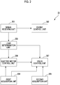
- Fig. 2 is a schematic block diagram showing a software configuration of the engine controller according to the first embodiment.
- the engine controller 13 includes a signal receiving unit 301, an engine control unit 302, a load determination unit 303, a first acquisition unit 304, a second acquisition unit 305, an electric motor control unit 306, and a valve control unit 307.
- the signal receiving unit 301 receives the engine control signal.
- the engine control unit 302 controls a fuel injection amount and a fuel injection timing of the engine 11.
- the load determination unit 303 determines whether or not the required load included in the engine control signal received by the signal receiving unit 301 exceeds a load threshold value.
- a load threshold value the maximum load which can be output by natural intake of the engine 11 can be used. That is, in a case where the required load exceeds the load threshold value, in order for the engine 11 to output the required load, it is necessary to increase a density of the intake air by the turbocharging system 14.
- the first acquisition unit 304 acquires a sensor signal indicating an outlet pressure of the electric compressor 143 from the first pressure sensor 147.
- the second acquisition unit 305 acquires a sensor signal indicating an outlet pressure of the turbocharger 145 from the second pressure sensor 148.
- the electric motor control unit 306 controls a rotation speed of the electric motor 1432.
- the valve control unit 307 controls an opening degree of the bypass valve 146.
- Fig. 3 is a flowchart showing a control operation of a turbocharging system by the engine controller according to the first embodiment.
- the engine control unit 302 controls the fuel injection amount and the fuel injection timing of the engine 11 (Step S1).
- the load determination unit 303 determines whether or not the required load of the engine 11 included in the engine control signal exceeds the load threshold value (Step S2). In a case where the required load exceeds the load threshold value (Step S2: YES), the electric motor control unit 306 starts supply of electricity from the battery 144 to the electric motor 1432. Accordingly, the electric motor 1432 starts (Step S3). After the electric motor 1432 starts, the rotation speed of the electric motor 1432 gradually increases to reach a target rotation speed. That is, the rotation speed of the electric motor 1432 immediately after electric motor 1432 starts does not reach the target rotation speed.
- the first acquisition unit 304 acquires the sensor signal indicating the outlet pressure of the electric compressor 143 from the first pressure sensor 147 (Step S4).
- the valve control unit 307 determines whether or not the outlet pressure indicated by the sensor signal acquired by the first acquisition unit 304 exceeds a first pressure threshold value (Step S5).
- the first pressure threshold value corresponds to an outlet pressure of the electric compressor 143 when the rotation speed of the electric compressor 143 exceeds a predetermined speed and air having a sufficient flow rate flows to the main intake flow path 1411 by the electric compressor 143.
- the first pressure threshold value is a value obtained by experiment or simulation in advance. In a case where the outlet pressure of the electric compressor 143 is equal to or less than the first pressure threshold value (Step S5: NO), the engine controller 13 returns the processing to Step S4, and thus, the sensor signal is acquired again.
- Step S6 the valve control unit 307 closes the bypass valve 146 (Step S6). That is, the valve control unit 307 changes the opening degree of the bypass valve 146 to 0%. Accordingly, the intake air flows into the turbocharger 145 through the main intake flow path 1411 without passing through the bypass flow path 1412. Accordingly, the electric compressor 143 starts an assistance of turbocharging. In this way, the valve control unit 307 switches the bypass valve 146 from an open state to a closed state after the electric motor 1432 is started by the electric motor control unit 306.
- the second acquisition unit 305 acquires the sensor signal indicating the outlet pressure of the turbocharger 145 from the second pressure sensor 148 (Step S7).
- the electric motor control unit 306 determines whether or not the outlet pressure indicated by the sensor signal acquired by the second acquisition unit 305 exceeds a second pressure threshold value (Step S8).
- the second pressure threshold value corresponds to an outlet pressure of the turbocharger 145 when the rotation speed of the turbocharger 145 exceeds a predetermined speed and the assistance of the turbocharging by the electric compressor 143 is not necessary.
- the second pressure threshold value is a value obtained by experiment or simulation in advance. In a case where the outlet pressure of the turbocharger 145 is equal to or less than the second pressure threshold value (Step S8: NO), the engine controller 13 returns the processing to Step S6, and thus, the sensor signal is acquired again.
- Step S8 the electric motor control unit 306 decreases the rotation speed of the electric motor 1432 to a predetermined speed (Step S9).
- the valve control unit 307 increases the opening degree of the bypass valve 146 by a predetermined amount (Step S10). In this case, the valve control unit 307 increases the opening degree of the bypass valve 146 by an opening degree corresponding to a decrease of the rotation speed with respect to the target rotation speed of the electric motor 1432.
- the valve control unit 307 increases the opening degree of the bypass valve 146 by 5%.
- the electric motor control unit 306 determines whether or not the electric motor 1432 is stopped (Step S11). In a case where the electric motor 1432 is not stopped (Step S11: NO), the engine controller 13 returns the processing to Step S9 so as to decrease the rotation speed of the electric motor 1432 and increase the opening degree of the bypass valve 146. Accordingly, when the rotation of the electric motor 1432 is stopped, the opening degree of the bypass valve 146 becomes 100%. In a case where the electric motor 1432 is stopped (Step S11: YES), the engine controller 13 completes the control operation of the electric compressor 143.
- the valve control unit 307 controls the opening degree of the bypass valve 146 to an opening degree corresponding to the required load (Step S12).
- the valve control unit 307 changes the opening degree of the bypass valve 146 to an opening degree corresponding to a ratio of the required load with respect to the load threshold value. That is, the valve control unit 307 performs the control such that the opening degree of the bypass valve 146 monotonically increases with respect to the required load. Accordingly, the flow rate of the intake air flowing through the intake flow path 141 monotonically increases with respect to the required load.
- the bypass valve 146 can realize the same function as that of a throttle valve in the related art.
- the valve control unit 307 performs the control such that the opening degree of the bypass valve 146 monotonically increases with respect to the required load. Accordingly, the engine system 1 can adjust the flow rate of the intake air at the time of a partial load without having a throttle valve.
- the engine controller 13 can limit the flow rate of the intake air without depending on the throttle valve. Accordingly, compared to a case where the flow rate of the intake air is adjusted by the throttle valve, in the engine controller 13, it is possible to decrease a pumping loss.
- the valve control unit 307 switches the bypass valve 146 from the open state to the closed state. Accordingly, the valve control unit 307 can prevent the supply air pressure immediately after the electric motor 1432 starts from decreasing. Particularly, according to the first embodiment, in a case where the outlet pressure of the electric compressor 143 exceeds the first pressure threshold value, the valve control unit 307 switches the bypass valve 146 from the open state to the closed state. Accordingly, after the rotation speed of the electric motor 1432 reliably reaches a constant value, the valve control unit 307 can close the bypass valve 146.
- the engine controller 13 in the case where the outlet pressure of the turbocharger 145 exceeds the second pressure threshold value, gradually decreases the speed of the electric motor 1432 and switches the bypass valve 146 from the closed state to the open state at a speed corresponding to the rotation speed of the electric motor 1432. In this way, the speed of the electric motor 1432 and the opening degree of the bypass valve 146 are gradually changed, and thus, it is possible to decrease influences of a resistance caused by deceleration of the electric compressor 143. That is, according to the engine controller 13 of the first embodiment, it is possible to prevent the turbocharging amount of the turbocharging system 14 from rapidly decreasing.
- the valve control unit 307 controls the opening degree of the bypass valve 146.
- the present invention is not limited to this.
- a valve control unit 307 may control an opening degree of a bypass valve 146.
- a valve control unit 307 may control an opening degree of a bypass valve 146. For example, the valve control unit 307 may close the bypass valve 146 when 0.1 seconds are elapsed after an electric motor control unit 306 starts the electric motor 1432.
- the electric motor control unit 306 controls the rotation speed of the electric motor 1432.
- the present invention is not limited thereto.
- an electric motor control unit 306 may control a rotation speed of an electric motor 1432.
- Fig. 4 is a schematic configuration diagram showing a modification example of the engine system according to the embodiment.
- the electric compressor 143 is provided at a front stage of the turbocharger 145.
- the present invention is not limited thereto.
- an engine controller 13 can exert effects similar to those of the above-described embodiment.
- the engine controller 13 controls the engine 11 and the turbocharging system 14.
- the present invention is not limited thereto.
- a turbo controller which controls a turbocharging system 14 separately from an engine controller 13 may be provided. In this case, when the required load is less than the load threshold value, the engine controller 13 outputs an opening degree command of the bypass valve 146 to the turbo controller.
- Fig. 5 is a schematic block diagram showing a configuration of a computer according to at least one embodiment.
- a computer 900 includes a CPU 901, a main memory 902, a storage 903, and an interface 904.
- the above-described engine controller 13 is installed in the computer 900.
- the above-described operations of the respective processing units are stored in the storage 903 in the form of a program.
- the CPU 901 reads the program from the storage 903, develops the program in the main memory 902, and executes the processing according to the program.
- the storage 903 is an example of a non-transitory tangible medium.
- the non-transitory tangible media include a magnetic disk, a magneto-optical disk, an optical disk, a semiconductor memory or the like connected via an interface 904.
- the distributed computer 900 may develop the program in the main memory 902 and execute the processing.
- the program may be provided to realize a portion of the above-mentioned functions. Moreover, the program may be a so-called difference file (difference program) which realizes the above-described functions by a combination with other programs already stored in the storage 903.
- difference file difference program
- the intake flow path passing through the first compressor is closed by the stopped first compressor. That is, in the case where the required load is equal to or less than the load threshold value, most of the intake air is supplied to the engine through the bypass flow path. Accordingly, in the control device according to at least one of the above-described aspects, by controlling the opening degree of the on-off valve which opens or closes the bypass flow path in the case where the required load is equal to or less than the load threshold value, it is possible to adjust the inflow amount of the intake air of the engine. Accordingly, in the engine system, it is possible to adjust the inflow amount of the intake air of the engine without having the throttle valve.
Abstract
Description
- The present invention relates to an engine system, an engine system control device, an engine system control method, and a program.
- Efficiency of a turbocharger depends on energy that a turbine receives from exhaust air. Therefore, effects of the turbocharger are small in a low rotation region where the amount of exhaust air from an engine is small. Accordingly, an engine system has been studied, in which a turbocharger and an electric compressor are provided in an air supply path and turbocharging can be performed even in a case where the amount of exhaust air is small (refer to PTL1).
- [PTL 1]
US Patent No. 6920756 - In general, in order to control a load of an engine, a throttle valve is provided in an engine system. The throttle valve is a valve which adjusts an inflow amount of intake air of the engine. Meanwhile, if the engine system has a turbocharging system, the number of parts increases, and thus, a cost of the engine system increases.
- An object of the present invention is to provide an engine system, an engine system control device, an engine system control method, and a program capable of decreasing the number of parts in an engine system including a turbocharger and an electric compressor.
- According to a first aspect of the present invention, there is provided a control device for an engine system including an engine, a first compressor which is provided in an intake flow path through which intake air supplied to the engine flows and is driven to compress the intake air, an electric motor which drives the first compressor, a second compressor which is provided in the intake flow path independently of the first compressor and compresses the intake air, a turbine which is provided in an exhaust flow path through which exhaust air from the engine flows and is rotated by the exhaust air so as to drive the second compressor, a bypass flow path which is connected to the intake flow path and bypasses the first compressor, and an on-off valve which opens or closes the bypass flow path, the control device including: a load determination unit which determines whether or not a load required by the engine exceeds a load threshold value; an electric motor control unit which starts the electric motor in a case where the required load exceeds the load threshold value; and a valve control unit which performs a control such that an opening degree of the on-off valve monotonically increases with respect to the required load in a case where the required load is equal to or less than the load threshold value and switches the on-off valve from an open state to a closed state in a case where the electric motor starts.
- According to a second aspect of the present invention, in the control device of an engine system according to the first aspect, the valve control unit may switch the on-off valve from an open state to a closed state after the electric motor is started by the electric motor control unit.
- According to a third aspect of the present invention, in the control device of an engine system according to the second aspect, the control device may further a first acquisition unit which acquires a physical quantity relating to a rotation of the first compressor, and the valve control unit may switch the on-off valve from the open state to the closed state after the electric motor starts and in a case where the physical quantity acquired by the first acquisition unit exceeds a predetermined threshold value.
- According to a fourth aspect of the present invention, in the control device of an engine system according to any one of the first to third aspects, the control device may further include a second acquisition unit which acquires a physical quantity relating to a rotation of the second compressor, the electric motor control unit may stop the electric motor in a case where the physical quantity acquired by the second acquisition unit exceeds a predetermined threshold value, and the valve control unit may switch the on-off valve from the closed state to the open state at a speed corresponding to a rotation speed of the electric motor.
- According to a fifth aspect of the present invention, there is provided an engine system, including: an engine; a first compressor which is provided in an intake flow path through which intake air supplied to the engine flows and is driven to compress the intake air; an electric motor which drives the first compressor; a second compressor which is provided in the intake flow path independently of the first compressor and compresses the intake air; a turbine which is provided in an exhaust flow path through which exhaust air from the engine flows and is rotated by the exhaust air so as to drive the second compressor; a bypass flow path which is connected to the intake flow path and bypasses the first compressor; an on-off valve which opens or closes the bypass flow path; and the control device according to any one of the first to fifth aspects.
- According to a seventh aspect of the present invention, there is provided a control method for an engine system including an engine, a first compressor which is provided in an intake flow path through which intake air supplied to the engine flows and is driven to compress the intake air, an electric motor which drives the first compressor, a second compressor which is provided in the intake flow path independently of the first compressor and compresses the intake air, a turbine which is provided in an exhaust flow path through which exhaust air from the engine flows and is rotated by the exhaust air so as to drive the second compressor, a bypass flow path which is connected to the intake flow path and bypasses the first compressor, and an on-off valve which opens or closes the bypass flow path, the control method including: determining whether or not a load required by the engine exceeds a load threshold value; starting the electric motor in a case where the required load exceeds the load threshold value; switching the on-off valve from an open state to a closed state in a case where the electric motor starts; and performing a control such that an opening degree of the on-off valve monotonically increases with respect to the required load in a case where the required load is equal to or less than the load threshold value.
- According to an eighth aspect of the present invention, there is provided a program for causing a computer of a control device for an engine system including an engine, a first compressor which is provided in an intake flow path through which intake air supplied to the engine flows and is driven to compress the intake air, an electric motor which drives the first compressor, a second compressor which is provided in the intake flow path independently of the first compressor and compresses the intake air, a turbine which is provided in an exhaust flow path through which exhaust air from the engine flows and is rotated by the exhaust air so as to drive the second compressor, a bypass flow path which is connected to the intake flow path and bypasses the first compressor, and an on-off valve which opens or closes the bypass flow path, to execute: determining whether or not a load required by the engine exceeds a load threshold value; starting the electric motor in a case where the required load exceeds the load threshold value; switching the on-off valve from an open state to a closed state in a case where the electric motor starts; and performing a control such that an opening degree of the on-off valve monotonically increases with respect to the required load in a case where the required load is equal to or less than the load threshold value.
- In the case where the required load is equal to or less than the load threshold value, the intake flow path passing through the first compressor is closed by the stopped first compressor. That is, in the case where the required load is equal to or less than the load threshold value, most of the intake air is supplied to the engine through the bypass flow path. Accordingly, in the control device according to at least one of the above-described aspects, by controlling the opening degree of the on-off valve which opens or closes the bypass flow path in the case where the required load is equal to or less than the load threshold value, it is possible to adjust the inflow amount of the intake air of the engine. Accordingly, in the engine system, it is possible to adjust the inflow amount of the intake air of the engine without having the throttle valve.
-
-
Fig. 1 is a schematic configuration diagram of an engine system according to a first embodiment. -
Fig. 2 is a schematic block diagram showing a software configuration of an engine controller according to the first embodiment. -
Fig. 3 is a flowchart showing a control operation of a turbocharging system by the engine controller according to the first embodiment. -
Fig. 4 is a schematic configuration diagram showing a modification example of the engine system according to the embodiment. -
Fig. 5 is a schematic block diagram showing a configuration of a computer according to at least one embodiment. - Hereinafter, embodiments will be described in detail with reference to the drawings.
-
Fig. 1 is a schematic configuration diagram of an engine system according to a first embodiment. - The
engine system 1 includes anengine 11, anengine controller 13, aturbocharging system 14, and anintercooler 15. Theengine system 1 according to the first embodiment does not have a throttle valve which controls a flow rate of intake air supplied to theengine 11. - Examples of the
engine 11 include a gasoline engine and a diesel engine. - Based on an engine control signal including a rotation speed and a required load, the
engine controller 13 performs adjustment of a fuel injection amount of theengine 11, a control of theturbocharging system 14, and other controls. The required load is a load which is required by the engine. Theengine controller 13 is an example of an engine system control device. - The
turbocharging system 14 is a system which increases a density of the intake air of theengine 11 to obtain high combustion energy. - The
intercooler 15 cools the intake air compressed by theturbocharging system 14. - The
turbocharging system 14 according to the first embodiment includes anintake flow path 141, anexhaust flow path 142, anelectric compressor 143, abattery 144, aturbocharger 145, a bypass valve 146 (on-off valve), afirst pressure sensor 147, and asecond pressure sensor 148. - The
intake flow path 141 is a pipe through which the intake air flows to theengine 11. Theintake flow path 141 including a mainintake flow path 1411 passing through theturbocharger 145 and theelectric compressor 143 and abypass flow path 1412 passing through theturbocharger 145 without passing through theelectric compressor 143. - The
exhaust flow path 142 is a pipe through which the exhaust air flows from theengine 11. - The
electric compressor 143 is a device which compresses the intake air of theengine 11 by electricity supplied from thebattery 144. Theelectric compressor 143 includes a compressor 1431 (first compressor) and anelectric motor 1432. Thecompressor 1431 is provided in the mainintake flow path 1411 of theintake flow path 141. Thecompressor 1431 is rotated to compress the intake air. Theelectric motor 1432 receives the supply of electricity from thebattery 144 so as to be driven. Theelectric motor 1432 and thecompressor 1431 are rotated by a common shaft. Accordingly, theelectric motor 1432 drives thecompressor 1431. - The
turbocharger 145 is a device which compresses the intake air of theengine 11 by the exhaust air of theengine 11. Theturbocharger 145 includes a compressor 1451 (second compressor) and aturbine 1452. Thecompressor 1451 is provided in theintake flow path 141 of theengine 11. Thecompressor 1451 is rotated to compress the intake air. Theturbine 1452 is provided in theexhaust flow path 142 of theengine 11. Theturbine 1452 and thecompressor 1451 are rotated by a common shaft. Accordingly, theturbine 1452 is rotated by the exhaust air to drive thecompressor 1451. - The
bypass valve 146 is provided in thebypass flow path 1412 in theintake flow path 141. If thebypass valve 146 is opened, a flow rate of the intake air passing through theelectric compressor 143 decreases. If thebypass valve 146 is closed, the flow rate of the intake air passing through theelectric compressor 143 increases. - The
first pressure sensor 147 measures an outlet pressure of the electric compressor 143 (compressor 1431). - The
second pressure sensor 148 measures an outlet pressure of the turbocharger 145 (compressor 1451). -
Fig. 2 is a schematic block diagram showing a software configuration of the engine controller according to the first embodiment. - The
engine controller 13 includes asignal receiving unit 301, anengine control unit 302, aload determination unit 303, afirst acquisition unit 304, asecond acquisition unit 305, an electricmotor control unit 306, and avalve control unit 307. - The
signal receiving unit 301 receives the engine control signal. - Based on the engine control signal received by the
signal receiving unit 301, theengine control unit 302 controls a fuel injection amount and a fuel injection timing of theengine 11. - The
load determination unit 303 determines whether or not the required load included in the engine control signal received by thesignal receiving unit 301 exceeds a load threshold value. For example, as the load threshold value, the maximum load which can be output by natural intake of theengine 11 can be used. That is, in a case where the required load exceeds the load threshold value, in order for theengine 11 to output the required load, it is necessary to increase a density of the intake air by theturbocharging system 14. - The
first acquisition unit 304 acquires a sensor signal indicating an outlet pressure of theelectric compressor 143 from thefirst pressure sensor 147. - The
second acquisition unit 305 acquires a sensor signal indicating an outlet pressure of theturbocharger 145 from thesecond pressure sensor 148. - Based on a determination result of the
load determination unit 303 and the sensor signal acquired by thesecond acquisition unit 305, the electricmotor control unit 306 controls a rotation speed of theelectric motor 1432. - Based on the determination result of the
load determination unit 303 and the sensor signal acquired by thefirst acquisition unit 304, thevalve control unit 307 controls an opening degree of thebypass valve 146. -
Fig. 3 is a flowchart showing a control operation of a turbocharging system by the engine controller according to the first embodiment. - If the
signal receiving unit 301 of theengine controller 13 receives the engine control signal from theengine controller 13, based on the engine control signal, theengine control unit 302 controls the fuel injection amount and the fuel injection timing of the engine 11 (Step S1). Theload determination unit 303 determines whether or not the required load of theengine 11 included in the engine control signal exceeds the load threshold value (Step S2). In a case where the required load exceeds the load threshold value (Step S2: YES), the electricmotor control unit 306 starts supply of electricity from thebattery 144 to theelectric motor 1432. Accordingly, theelectric motor 1432 starts (Step S3). After theelectric motor 1432 starts, the rotation speed of theelectric motor 1432 gradually increases to reach a target rotation speed. That is, the rotation speed of theelectric motor 1432 immediately afterelectric motor 1432 starts does not reach the target rotation speed. - The
first acquisition unit 304 acquires the sensor signal indicating the outlet pressure of theelectric compressor 143 from the first pressure sensor 147 (Step S4). Thevalve control unit 307 determines whether or not the outlet pressure indicated by the sensor signal acquired by thefirst acquisition unit 304 exceeds a first pressure threshold value (Step S5). The first pressure threshold value corresponds to an outlet pressure of theelectric compressor 143 when the rotation speed of theelectric compressor 143 exceeds a predetermined speed and air having a sufficient flow rate flows to the mainintake flow path 1411 by theelectric compressor 143. The first pressure threshold value is a value obtained by experiment or simulation in advance. In a case where the outlet pressure of theelectric compressor 143 is equal to or less than the first pressure threshold value (Step S5: NO), theengine controller 13 returns the processing to Step S4, and thus, the sensor signal is acquired again. - Meanwhile, in a case where the outlet pressure of the
electric compressor 143 exceeds the first pressure threshold value (Step S5: YES), thevalve control unit 307 closes the bypass valve 146 (Step S6). That is, thevalve control unit 307 changes the opening degree of thebypass valve 146 to 0%. Accordingly, the intake air flows into theturbocharger 145 through the mainintake flow path 1411 without passing through thebypass flow path 1412. Accordingly, theelectric compressor 143 starts an assistance of turbocharging. In this way, thevalve control unit 307 switches thebypass valve 146 from an open state to a closed state after theelectric motor 1432 is started by the electricmotor control unit 306. - If the
electric compressor 143 starts an assistance in compression of the intake air, thesecond acquisition unit 305 acquires the sensor signal indicating the outlet pressure of theturbocharger 145 from the second pressure sensor 148 (Step S7). The electricmotor control unit 306 determines whether or not the outlet pressure indicated by the sensor signal acquired by thesecond acquisition unit 305 exceeds a second pressure threshold value (Step S8). The second pressure threshold value corresponds to an outlet pressure of theturbocharger 145 when the rotation speed of theturbocharger 145 exceeds a predetermined speed and the assistance of the turbocharging by theelectric compressor 143 is not necessary. The second pressure threshold value is a value obtained by experiment or simulation in advance. In a case where the outlet pressure of theturbocharger 145 is equal to or less than the second pressure threshold value (Step S8: NO), theengine controller 13 returns the processing to Step S6, and thus, the sensor signal is acquired again. - Meanwhile, in a case where the outlet pressure of the
turbocharger 145 exceeds the second pressure threshold value (Step S8: YES), the electricmotor control unit 306 decreases the rotation speed of theelectric motor 1432 to a predetermined speed (Step S9). In addition, thevalve control unit 307 increases the opening degree of thebypass valve 146 by a predetermined amount (Step S10). In this case, thevalve control unit 307 increases the opening degree of thebypass valve 146 by an opening degree corresponding to a decrease of the rotation speed with respect to the target rotation speed of theelectric motor 1432. For example, in a case where the electricmotor control unit 306 decreases the rotation speed by 5% with respect to the target rotation speed of theelectric motor 1432 under the control of Step S3, thevalve control unit 307 increases the opening degree of thebypass valve 146 by 5%. The electricmotor control unit 306 determines whether or not theelectric motor 1432 is stopped (Step S11). In a case where theelectric motor 1432 is not stopped (Step S11: NO), theengine controller 13 returns the processing to Step S9 so as to decrease the rotation speed of theelectric motor 1432 and increase the opening degree of thebypass valve 146. Accordingly, when the rotation of theelectric motor 1432 is stopped, the opening degree of thebypass valve 146 becomes 100%. In a case where theelectric motor 1432 is stopped (Step S11: YES), theengine controller 13 completes the control operation of theelectric compressor 143. - In addition, in a case where the required load is equal to or less than the load threshold value in Step S2 (Step S2: NO), the
valve control unit 307 controls the opening degree of thebypass valve 146 to an opening degree corresponding to the required load (Step S12). For example, thevalve control unit 307 changes the opening degree of thebypass valve 146 to an opening degree corresponding to a ratio of the required load with respect to the load threshold value. That is, thevalve control unit 307 performs the control such that the opening degree of thebypass valve 146 monotonically increases with respect to the required load. Accordingly, the flow rate of the intake air flowing through theintake flow path 141 monotonically increases with respect to the required load. According to this control, in theengine controller 13, thebypass valve 146 can realize the same function as that of a throttle valve in the related art. - As described above, according to the first embodiment, in the case where the required load is equal to or less than the load threshold value, the
valve control unit 307 performs the control such that the opening degree of thebypass valve 146 monotonically increases with respect to the required load. Accordingly, theengine system 1 can adjust the flow rate of the intake air at the time of a partial load without having a throttle valve. - When the required load is equal to or less than the load threshold value, in the
engine 11, it is necessary to decrease an air flow rate, and thus, theelectric compressor 143 is not driven. Meanwhile, when the required load exceeds the load threshold value, in theengine 11, it is necessary to increase the air flow rate, and thus, limitation of the flow rate of the intake air by the throttle valve in the related art is not performed. As described above, a timing at which the flow rate of the intake air should be limited and a timing at which theelectric compressor 143 is not driven do not overlap each other, and thus, the limitation of the flow rate of the intake air and a flow path change to theelectric compressor 143 can be integrated in thebypass valve 146. - According to the first embodiment, the
engine controller 13 can limit the flow rate of the intake air without depending on the throttle valve. Accordingly, compared to a case where the flow rate of the intake air is adjusted by the throttle valve, in theengine controller 13, it is possible to decrease a pumping loss. - According to the first embodiment, after the
electric motor 1432 is started by the electricmotor control unit 306, thevalve control unit 307 switches thebypass valve 146 from the open state to the closed state. Accordingly, thevalve control unit 307 can prevent the supply air pressure immediately after theelectric motor 1432 starts from decreasing. Particularly, according to the first embodiment, in a case where the outlet pressure of theelectric compressor 143 exceeds the first pressure threshold value, thevalve control unit 307 switches thebypass valve 146 from the open state to the closed state. Accordingly, after the rotation speed of theelectric motor 1432 reliably reaches a constant value, thevalve control unit 307 can close thebypass valve 146. - According to the first embodiment, in the case where the outlet pressure of the
turbocharger 145 exceeds the second pressure threshold value, theengine controller 13 gradually decreases the speed of theelectric motor 1432 and switches thebypass valve 146 from the closed state to the open state at a speed corresponding to the rotation speed of theelectric motor 1432. In this way, the speed of theelectric motor 1432 and the opening degree of thebypass valve 146 are gradually changed, and thus, it is possible to decrease influences of a resistance caused by deceleration of theelectric compressor 143. That is, according to theengine controller 13 of the first embodiment, it is possible to prevent the turbocharging amount of theturbocharging system 14 from rapidly decreasing. - Hereinbefore, the embodiment is described above in detail with reference to the drawings. However, specific configurations are not limited to those described above, and various design changes or the like can be made.
- For example, in the above-described embodiment, based on the outlet pressure of the
electric compressor 143, thevalve control unit 307 controls the opening degree of thebypass valve 146. However, the present invention is not limited to this. For example, based on other physical quantities relating to a rotation speed or torque of anelectric compressor 143 or a rotation of theelectric compressor 143, avalve control unit 307 according to another embodiment may control an opening degree of abypass valve 146. Still another embodiment, based on an elapsed time from start of anelectric motor 1432, avalve control unit 307 may control an opening degree of abypass valve 146. For example, thevalve control unit 307 may close thebypass valve 146 when 0.1 seconds are elapsed after an electricmotor control unit 306 starts theelectric motor 1432. - In the above-described embodiment, based on the outlet pressure of the
turbocharger 145, the electricmotor control unit 306 controls the rotation speed of theelectric motor 1432. However, the present invention is not limited thereto. For example, based on other physical quantities relating to a rotation speed or torque of aturbocharger 145 or a rotation of theturbocharger 145, an electricmotor control unit 306 according to still another embodiment may control a rotation speed of anelectric motor 1432. -
Fig. 4 is a schematic configuration diagram showing a modification example of the engine system according to the embodiment. - In the above-described embodiment, as shown in
Fig. 1 , theelectric compressor 143 is provided at a front stage of theturbocharger 145. However, the present invention is not limited thereto. For example, in still another embodiment, as shown inFig. 4 , even when aturbocharger 145 is provided at a front stage of anelectric compressor 143, anengine controller 13 can exert effects similar to those of the above-described embodiment. - In the above-described embodiment, the
engine controller 13 controls theengine 11 and theturbocharging system 14. However, the present invention is not limited thereto. For example, in still another embodiment, a turbo controller which controls aturbocharging system 14 separately from anengine controller 13 may be provided. In this case, when the required load is less than the load threshold value, theengine controller 13 outputs an opening degree command of thebypass valve 146 to the turbo controller. -
Fig. 5 is a schematic block diagram showing a configuration of a computer according to at least one embodiment. - A
computer 900 includes aCPU 901, amain memory 902, astorage 903, and aninterface 904. - The above-described
engine controller 13 is installed in thecomputer 900. In addition, the above-described operations of the respective processing units are stored in thestorage 903 in the form of a program. TheCPU 901 reads the program from thestorage 903, develops the program in themain memory 902, and executes the processing according to the program. - In addition, in at least one embodiment, the
storage 903 is an example of a non-transitory tangible medium. Other examples of the non-transitory tangible media include a magnetic disk, a magneto-optical disk, an optical disk, a semiconductor memory or the like connected via aninterface 904. In a case where the program is distributed to thecomputer 900 via a communication line, the distributedcomputer 900 may develop the program in themain memory 902 and execute the processing. - The program may be provided to realize a portion of the above-mentioned functions. Moreover, the program may be a so-called difference file (difference program) which realizes the above-described functions by a combination with other programs already stored in the
storage 903. - According to the engine system control device, in the case where the required load is equal to or less than the load threshold value, the intake flow path passing through the first compressor is closed by the stopped first compressor. That is, in the case where the required load is equal to or less than the load threshold value, most of the intake air is supplied to the engine through the bypass flow path. Accordingly, in the control device according to at least one of the above-described aspects, by controlling the opening degree of the on-off valve which opens or closes the bypass flow path in the case where the required load is equal to or less than the load threshold value, it is possible to adjust the inflow amount of the intake air of the engine. Accordingly, in the engine system, it is possible to adjust the inflow amount of the intake air of the engine without having the throttle valve.
-
- 1: engine system
- 11: engine
- 13: engine controller
- 14: turbocharging system
- 141: intake flow path
- 1411: main intake flow path
- 1412: bypass flow path
- 142: exhaust flow path
- 143: electric compressor
- 1431: compressor
- 1432: electric motor
- 144: battery
- 145: turbocharger
- 1451: compressor
- 1452: turbine
- 146: bypass valve
- 147: first pressure sensor
- 148: second pressure sensor
- 301: signal receiving unit
- 302: engine control unit
- 303: load determination unit
- 304: first acquisition unit
- 305: second acquisition unit
- 306: electric motor control unit
- 307: valve control unit
Claims (7)
- A control device for an engine system including
an engine,
a first compressor which is provided in an intake flow path through which intake air supplied to the engine flows and is driven to compress the intake air,
an electric motor which drives the first compressor,
a second compressor which is provided in the intake flow path independently of the first compressor and compresses the intake air,
a turbine which is provided in an exhaust flow path through which exhaust air from the engine flows and is rotated by the exhaust air so as to drive the second compressor,
a bypass flow path which is connected to the intake flow path and bypasses the first compressor, and
an on-off valve which opens or closes the bypass flow path,
the control device comprising:a load determination unit which determines whether or not a load required by the engine exceeds a load threshold value;an electric motor control unit which starts the electric motor in a case where the required load exceeds the load threshold value; anda valve control unit which performs a control such that an opening degree of the on-off valve monotonically increases with respect to the required load in a case where the required load is equal to or less than the load threshold value and switches the on-off valve from an open state to a closed state in a case where the electric motor starts. - The control device for an engine system according to claim 1,
wherein the valve control unit switches the on-off valve from an open state to a closed state after the electric motor is started by the electric motor control unit. - The control device for an engine system according to claim 2, further comprising:a first acquisition unit which acquires a physical quantity relating to a rotation of the first compressor,wherein the valve control unit switches the on-off valve from the open state to the closed state after the electric motor starts and in a case where the physical quantity acquired by the first acquisition unit exceeds a predetermined threshold value.
- The control device for an engine system according to any one of claims 1 to 3, further comprising:a second acquisition unit which acquires a physical quantity relating to a rotation of the second compressor,wherein the electric motor control unit stops the electric motor in a case where the physical quantity acquired by the second acquisition unit exceeds a predetermined threshold value, andwherein the valve control unit switches the on-off valve from the closed state to the open state at a speed corresponding to a rotation speed of the electric motor.
- An engine system comprising:an engine;a first compressor which is provided in an intake flow path through which intake air supplied to the engine flows and is driven to compress the intake air;an electric motor which drives the first compressor;a second compressor which is provided in the intake flow path independently of the first compressor and compresses the intake air;a turbine which is provided in an exhaust flow path through which exhaust air from the engine flows and is rotated by the exhaust air so as to drive the second compressor;a bypass flow path which is connected to the intake flow path and bypasses the first compressor;an on-off valve which opens or closes the bypass flow path; andthe control device according to any one of claims 1 to 4.
- A control method for an engine system including
an engine,
a first compressor which is provided in an intake flow path through which intake air supplied to the engine flows and is driven to compress the intake air,
an electric motor which drives the first compressor,
a second compressor which is provided in the intake flow path independently of the first compressor and compresses the intake air,
a turbine which is provided in an exhaust flow path through which exhaust air from the engine flows and is rotated by the exhaust air so as to drive the second compressor,
a bypass flow path which is connected to the intake flow path and bypasses the first compressor, and
an on-off valve which opens or closes the bypass flow path,
the control method comprising:determining whether or not a load required by the engine exceeds a load threshold value;starting the electric motor in a case where the required load exceeds the load threshold value;switching the on-off valve from an open state to a closed state in a case where the electric motor starts; andperforming a control such that an opening degree of the on-off valve monotonically increases with respect to the required load in a case where the required load is equal to or less than the load threshold value. - A program for causing a computer of a control device for an engine system including
an engine,
a first compressor which is provided in an intake flow path through which intake air supplied to the engine flows and is driven to compress the intake air,
an electric motor which drives the first compressor,
a second compressor which is provided in the intake flow path independently of the first compressor and compresses the intake air,
a turbine which is provided in an exhaust flow path through which exhaust air from the engine flows and is rotated by the exhaust air so as to drive the second compressor,
a bypass flow path which is connected to the intake flow path and bypasses the first compressor, and
an on-off valve which opens or closes the bypass flow path, to execute:determining whether or not a load required by the engine exceeds a load threshold value;starting the electric motor in a case where the required load exceeds the load threshold value;switching the on-off valve from an open state to a closed state in a case where the electric motor starts; andperforming a control such that an opening degree of the on-off valve monotonically increases with respect to the required load in a case where the required load is equal to or less than the load threshold value.
Applications Claiming Priority (1)
| Application Number | Priority Date | Filing Date | Title |
|---|---|---|---|
| PCT/JP2016/057019 WO2017154082A1 (en) | 2016-03-07 | 2016-03-07 | Engine system, engine system control device, engine system control method, and program |
Publications (3)
| Publication Number | Publication Date |
|---|---|
| EP3409919A1 true EP3409919A1 (en) | 2018-12-05 |
| EP3409919A4 EP3409919A4 (en) | 2019-04-03 |
| EP3409919B1 EP3409919B1 (en) | 2022-02-23 |
Family
ID=59790147
Family Applications (1)
| Application Number | Title | Priority Date | Filing Date |
|---|---|---|---|
| EP16893414.9A Active EP3409919B1 (en) | 2016-03-07 | 2016-03-07 | Control device for an engine system with turbocharger and electrically driven compressor |
Country Status (5)
| Country | Link |
|---|---|
| US (1) | US10753269B2 (en) |
| EP (1) | EP3409919B1 (en) |
| JP (1) | JP6676142B2 (en) |
| CN (1) | CN108699949B (en) |
| WO (1) | WO2017154082A1 (en) |
Families Citing this family (4)
| Publication number | Priority date | Publication date | Assignee | Title |
|---|---|---|---|---|
| JP7027195B2 (en) * | 2018-02-27 | 2022-03-01 | 三菱重工マリンマシナリ株式会社 | Motor system and its control method |
| CN109372628A (en) * | 2018-10-30 | 2019-02-22 | 东风商用车有限公司 | A kind of electronic pressurization realization Miller cycle diesel engine system |
| CN109252942B (en) * | 2018-11-08 | 2023-06-06 | 广西玉柴机器股份有限公司 | Electric auxiliary boost control method and system for engine |
| US11473538B2 (en) * | 2021-02-23 | 2022-10-18 | Ford Global Technologies, Llc | Methods and systems to decrease charge air cooler condensate |
Family Cites Families (17)
| Publication number | Priority date | Publication date | Assignee | Title |
|---|---|---|---|---|
| DE19934606A1 (en) | 1999-07-23 | 2001-01-25 | Steyr Nutzfahrzeuge Ag Steyr | Device and method for increasing the performance of an internal combustion engine of a vehicle charged by means of an exhaust gas turbocharger |
| DE10023022A1 (en) | 2000-05-11 | 2001-11-22 | Borgwarner Inc | Supercharged internal combustion engine |
| US6938420B2 (en) * | 2002-08-20 | 2005-09-06 | Nissan Motor Co., Ltd. | Supercharger for internal combustion engine |
| JP3951942B2 (en) * | 2003-03-17 | 2007-08-01 | 日産自動車株式会社 | Electric supercharging system |
| JP2005061243A (en) * | 2003-08-18 | 2005-03-10 | Nissan Motor Co Ltd | Supercharging device for internal combustion engine |
| JP4544120B2 (en) * | 2005-09-29 | 2010-09-15 | マツダ株式会社 | Engine supercharger |
| DE102010007601A1 (en) * | 2010-02-11 | 2011-08-11 | MTU Friedrichshafen GmbH, 88045 | Charged internal combustion engine |
| KR101234633B1 (en) * | 2010-09-30 | 2013-02-19 | 현대자동차주식회사 | System for correcting turbo lack |
| US9151215B2 (en) * | 2012-10-01 | 2015-10-06 | Fca Us Llc | Artificial aspiration methods and systems for increasing engine efficiency |
| US9599013B2 (en) * | 2013-04-15 | 2017-03-21 | Ford Global Technologies, Llc | Direct manifold boost assist device with throttle body manifold volume isolation |
| JP6377340B2 (en) | 2013-12-04 | 2018-08-22 | 三菱重工業株式会社 | Control device for supercharging system |
| JP6206163B2 (en) * | 2013-12-20 | 2017-10-04 | トヨタ自動車株式会社 | Internal combustion engine control system |
| WO2015186610A1 (en) | 2014-06-06 | 2015-12-10 | ヤンマー株式会社 | Engine device |
| JP6265838B2 (en) * | 2014-06-06 | 2018-01-24 | ヤンマー株式会社 | Engine equipment |
| JP2016011641A (en) | 2014-06-30 | 2016-01-21 | トヨタ自動車株式会社 | Supercharging system |
| DE102014213070A1 (en) | 2014-07-04 | 2016-01-07 | Mahle International Gmbh | Internal combustion engine |
| JP6015724B2 (en) * | 2014-09-02 | 2016-10-26 | トヨタ自動車株式会社 | Internal combustion engine system |
-
2016
- 2016-03-07 US US16/077,313 patent/US10753269B2/en active Active
- 2016-03-07 WO PCT/JP2016/057019 patent/WO2017154082A1/en active Application Filing
- 2016-03-07 JP JP2018503875A patent/JP6676142B2/en active Active
- 2016-03-07 EP EP16893414.9A patent/EP3409919B1/en active Active
- 2016-03-07 CN CN201680081984.8A patent/CN108699949B/en active Active
Also Published As
| Publication number | Publication date |
|---|---|
| US10753269B2 (en) | 2020-08-25 |
| JP6676142B2 (en) | 2020-04-08 |
| US20190078505A1 (en) | 2019-03-14 |
| CN108699949A (en) | 2018-10-23 |
| EP3409919A4 (en) | 2019-04-03 |
| WO2017154082A1 (en) | 2017-09-14 |
| JPWO2017154082A1 (en) | 2018-11-22 |
| EP3409919B1 (en) | 2022-02-23 |
| CN108699949B (en) | 2021-02-09 |
Similar Documents
| Publication | Publication Date | Title |
|---|---|---|
| EP3133273B1 (en) | Control device for a supercharged internal combustion engine | |
| US10753269B2 (en) | Engine system, engine system control device, engine system control method, and program | |
| EP3406878B1 (en) | Supercharging system, control device for supercharging system, control method for supercharging system, and program | |
| US6662562B2 (en) | Method and device for regulating the boost pressure of an internal combustion engine | |
| JP5680169B1 (en) | Control device and control method for internal combustion engine | |
| US8640459B2 (en) | Turbocharger control systems and methods for improved transient performance | |
| JP5786970B2 (en) | Control device for internal combustion engine | |
| US9708984B2 (en) | Regulating method for a turbocharger of an internal combustion engine, and turbocharger | |
| KR101714265B1 (en) | The controlling method of engine system equipped with supercharger | |
| CN107587947B (en) | Method and system for controlling vehicle supercharger | |
| CN107975417B (en) | Supercharged engine system of a motor vehicle | |
| CN108626000B (en) | Control device for internal combustion engine | |
| CN103195555A (en) | Control systems and methods for super turbo-charged engines | |
| CN107288742B (en) | Boost control method and system for cylinder-deactivated engine | |
| KR102223103B1 (en) | Method for determining the basic boost pressure of a gas guide system of an internal combustion engine and engine control for implementing the method | |
| US9273619B2 (en) | Supercharged engine and method of control | |
| JP2005201092A (en) | Supercharge system for internal combustion engine | |
| JP2016114046A (en) | Internal combustion engine | |
| JP2016050567A (en) | Internal combustion engine | |
| JP2016089738A (en) | Suction bypass control method for internal combustion engine and suction bypass control system for internal combustion engine | |
| JPH0861075A (en) | Maximum speed controlling method of engine with supercharger |
Legal Events
| Date | Code | Title | Description |
|---|---|---|---|
| STAA | Information on the status of an ep patent application or granted ep patent |
Free format text: STATUS: THE INTERNATIONAL PUBLICATION HAS BEEN MADE |
|
| PUAI | Public reference made under article 153(3) epc to a published international application that has entered the european phase |
Free format text: ORIGINAL CODE: 0009012 |
|
| STAA | Information on the status of an ep patent application or granted ep patent |
Free format text: STATUS: REQUEST FOR EXAMINATION WAS MADE |
|
| 17P | Request for examination filed |
Effective date: 20180827 |
|
| AK | Designated contracting states |
Kind code of ref document: A1 Designated state(s): AL AT BE BG CH CY CZ DE DK EE ES FI FR GB GR HR HU IE IS IT LI LT LU LV MC MK MT NL NO PL PT RO RS SE SI SK SM TR |
|
| AX | Request for extension of the european patent |
Extension state: BA ME |
|
| A4 | Supplementary search report drawn up and despatched |
Effective date: 20190304 |
|
| RIC1 | Information provided on ipc code assigned before grant |
Ipc: F02B 39/10 20060101ALI20190226BHEP Ipc: F02D 41/00 20060101ALI20190226BHEP Ipc: F02B 37/04 20060101AFI20190226BHEP Ipc: F02D 41/04 20060101ALI20190226BHEP Ipc: F02B 33/44 20060101ALN20190226BHEP Ipc: F02B 33/34 20060101ALI20190226BHEP Ipc: F02B 37/16 20060101ALI20190226BHEP Ipc: F02B 37/12 20060101ALI20190226BHEP |
|
| DAV | Request for validation of the european patent (deleted) | ||
| DAX | Request for extension of the european patent (deleted) | ||
| STAA | Information on the status of an ep patent application or granted ep patent |
Free format text: STATUS: EXAMINATION IS IN PROGRESS |
|
| 17Q | First examination report despatched |
Effective date: 20191113 |
|
| STAA | Information on the status of an ep patent application or granted ep patent |
Free format text: STATUS: EXAMINATION IS IN PROGRESS |
|
| RIC1 | Information provided on ipc code assigned before grant |
Ipc: F02B 37/04 20060101AFI20210324BHEP Ipc: F02B 37/16 20060101ALI20210324BHEP Ipc: F02D 41/04 20060101ALI20210324BHEP Ipc: F02B 33/34 20060101ALI20210324BHEP Ipc: F02D 23/02 20060101ALI20210324BHEP Ipc: F02B 37/12 20060101ALI20210324BHEP Ipc: F02B 37/007 20060101ALI20210324BHEP Ipc: F02B 39/10 20060101ALN20210324BHEP |
|
| RIC1 | Information provided on ipc code assigned before grant |
Ipc: F02B 37/04 20060101AFI20210407BHEP Ipc: F02B 37/16 20060101ALI20210407BHEP Ipc: F02D 41/04 20060101ALI20210407BHEP Ipc: F02B 33/34 20060101ALI20210407BHEP Ipc: F02D 23/02 20060101ALI20210407BHEP Ipc: F02B 37/12 20060101ALI20210407BHEP Ipc: F02B 37/007 20060101ALI20210407BHEP Ipc: F02B 39/10 20060101ALN20210407BHEP |
|
| RIC1 | Information provided on ipc code assigned before grant |
Ipc: F02B 39/10 20060101ALN20211021BHEP Ipc: F02B 37/007 20060101ALI20211021BHEP Ipc: F02B 37/12 20060101ALI20211021BHEP Ipc: F02D 23/02 20060101ALI20211021BHEP Ipc: F02B 33/34 20060101ALI20211021BHEP Ipc: F02D 41/04 20060101ALI20211021BHEP Ipc: F02B 37/16 20060101ALI20211021BHEP Ipc: F02B 37/04 20060101AFI20211021BHEP |
|
| GRAP | Despatch of communication of intention to grant a patent |
Free format text: ORIGINAL CODE: EPIDOSNIGR1 |
|
| STAA | Information on the status of an ep patent application or granted ep patent |
Free format text: STATUS: GRANT OF PATENT IS INTENDED |
|
| INTG | Intention to grant announced |
Effective date: 20211202 |
|
| GRAS | Grant fee paid |
Free format text: ORIGINAL CODE: EPIDOSNIGR3 |
|
| GRAA | (expected) grant |
Free format text: ORIGINAL CODE: 0009210 |
|
| STAA | Information on the status of an ep patent application or granted ep patent |
Free format text: STATUS: THE PATENT HAS BEEN GRANTED |
|
| AK | Designated contracting states |
Kind code of ref document: B1 Designated state(s): AL AT BE BG CH CY CZ DE DK EE ES FI FR GB GR HR HU IE IS IT LI LT LU LV MC MK MT NL NO PL PT RO RS SE SI SK SM TR |
|
| REG | Reference to a national code |
Ref country code: GB Ref legal event code: FG4D |
|
| REG | Reference to a national code |
Ref country code: CH Ref legal event code: EP |
|
| REG | Reference to a national code |
Ref country code: AT Ref legal event code: REF Ref document number: 1470631 Country of ref document: AT Kind code of ref document: T Effective date: 20220315 |
|
| REG | Reference to a national code |
Ref country code: IE Ref legal event code: FG4D |
|
| REG | Reference to a national code |
Ref country code: DE Ref legal event code: R096 Ref document number: 602016069468 Country of ref document: DE |
|
| REG | Reference to a national code |
Ref country code: LT Ref legal event code: MG9D |
|
| REG | Reference to a national code |
Ref country code: NL Ref legal event code: MP Effective date: 20220223 |
|
| REG | Reference to a national code |
Ref country code: AT Ref legal event code: MK05 Ref document number: 1470631 Country of ref document: AT Kind code of ref document: T Effective date: 20220223 |
|
| PG25 | Lapsed in a contracting state [announced via postgrant information from national office to epo] |
Ref country code: SE Free format text: LAPSE BECAUSE OF FAILURE TO SUBMIT A TRANSLATION OF THE DESCRIPTION OR TO PAY THE FEE WITHIN THE PRESCRIBED TIME-LIMIT Effective date: 20220223 Ref country code: RS Free format text: LAPSE BECAUSE OF FAILURE TO SUBMIT A TRANSLATION OF THE DESCRIPTION OR TO PAY THE FEE WITHIN THE PRESCRIBED TIME-LIMIT Effective date: 20220223 Ref country code: PT Free format text: LAPSE BECAUSE OF FAILURE TO SUBMIT A TRANSLATION OF THE DESCRIPTION OR TO PAY THE FEE WITHIN THE PRESCRIBED TIME-LIMIT Effective date: 20220623 Ref country code: NO Free format text: LAPSE BECAUSE OF FAILURE TO SUBMIT A TRANSLATION OF THE DESCRIPTION OR TO PAY THE FEE WITHIN THE PRESCRIBED TIME-LIMIT Effective date: 20220523 Ref country code: NL Free format text: LAPSE BECAUSE OF FAILURE TO SUBMIT A TRANSLATION OF THE DESCRIPTION OR TO PAY THE FEE WITHIN THE PRESCRIBED TIME-LIMIT Effective date: 20220223 Ref country code: LT Free format text: LAPSE BECAUSE OF FAILURE TO SUBMIT A TRANSLATION OF THE DESCRIPTION OR TO PAY THE FEE WITHIN THE PRESCRIBED TIME-LIMIT Effective date: 20220223 Ref country code: HR Free format text: LAPSE BECAUSE OF FAILURE TO SUBMIT A TRANSLATION OF THE DESCRIPTION OR TO PAY THE FEE WITHIN THE PRESCRIBED TIME-LIMIT Effective date: 20220223 Ref country code: ES Free format text: LAPSE BECAUSE OF FAILURE TO SUBMIT A TRANSLATION OF THE DESCRIPTION OR TO PAY THE FEE WITHIN THE PRESCRIBED TIME-LIMIT Effective date: 20220223 Ref country code: BG Free format text: LAPSE BECAUSE OF FAILURE TO SUBMIT A TRANSLATION OF THE DESCRIPTION OR TO PAY THE FEE WITHIN THE PRESCRIBED TIME-LIMIT Effective date: 20220523 |
|
| PG25 | Lapsed in a contracting state [announced via postgrant information from national office to epo] |
Ref country code: PL Free format text: LAPSE BECAUSE OF FAILURE TO SUBMIT A TRANSLATION OF THE DESCRIPTION OR TO PAY THE FEE WITHIN THE PRESCRIBED TIME-LIMIT Effective date: 20220223 Ref country code: LV Free format text: LAPSE BECAUSE OF FAILURE TO SUBMIT A TRANSLATION OF THE DESCRIPTION OR TO PAY THE FEE WITHIN THE PRESCRIBED TIME-LIMIT Effective date: 20220223 Ref country code: GR Free format text: LAPSE BECAUSE OF FAILURE TO SUBMIT A TRANSLATION OF THE DESCRIPTION OR TO PAY THE FEE WITHIN THE PRESCRIBED TIME-LIMIT Effective date: 20220524 Ref country code: FI Free format text: LAPSE BECAUSE OF FAILURE TO SUBMIT A TRANSLATION OF THE DESCRIPTION OR TO PAY THE FEE WITHIN THE PRESCRIBED TIME-LIMIT Effective date: 20220223 Ref country code: AT Free format text: LAPSE BECAUSE OF FAILURE TO SUBMIT A TRANSLATION OF THE DESCRIPTION OR TO PAY THE FEE WITHIN THE PRESCRIBED TIME-LIMIT Effective date: 20220223 |
|
| PG25 | Lapsed in a contracting state [announced via postgrant information from national office to epo] |
Ref country code: IS Free format text: LAPSE BECAUSE OF FAILURE TO SUBMIT A TRANSLATION OF THE DESCRIPTION OR TO PAY THE FEE WITHIN THE PRESCRIBED TIME-LIMIT Effective date: 20220623 |
|
| PG25 | Lapsed in a contracting state [announced via postgrant information from national office to epo] |
Ref country code: SM Free format text: LAPSE BECAUSE OF FAILURE TO SUBMIT A TRANSLATION OF THE DESCRIPTION OR TO PAY THE FEE WITHIN THE PRESCRIBED TIME-LIMIT Effective date: 20220223 Ref country code: SK Free format text: LAPSE BECAUSE OF FAILURE TO SUBMIT A TRANSLATION OF THE DESCRIPTION OR TO PAY THE FEE WITHIN THE PRESCRIBED TIME-LIMIT Effective date: 20220223 Ref country code: RO Free format text: LAPSE BECAUSE OF FAILURE TO SUBMIT A TRANSLATION OF THE DESCRIPTION OR TO PAY THE FEE WITHIN THE PRESCRIBED TIME-LIMIT Effective date: 20220223 Ref country code: EE Free format text: LAPSE BECAUSE OF FAILURE TO SUBMIT A TRANSLATION OF THE DESCRIPTION OR TO PAY THE FEE WITHIN THE PRESCRIBED TIME-LIMIT Effective date: 20220223 Ref country code: DK Free format text: LAPSE BECAUSE OF FAILURE TO SUBMIT A TRANSLATION OF THE DESCRIPTION OR TO PAY THE FEE WITHIN THE PRESCRIBED TIME-LIMIT Effective date: 20220223 Ref country code: CZ Free format text: LAPSE BECAUSE OF FAILURE TO SUBMIT A TRANSLATION OF THE DESCRIPTION OR TO PAY THE FEE WITHIN THE PRESCRIBED TIME-LIMIT Effective date: 20220223 |
|
| REG | Reference to a national code |
Ref country code: CH Ref legal event code: PL |
|
| REG | Reference to a national code |
Ref country code: DE Ref legal event code: R097 Ref document number: 602016069468 Country of ref document: DE |
|
| PG25 | Lapsed in a contracting state [announced via postgrant information from national office to epo] |
Ref country code: MC Free format text: LAPSE BECAUSE OF FAILURE TO SUBMIT A TRANSLATION OF THE DESCRIPTION OR TO PAY THE FEE WITHIN THE PRESCRIBED TIME-LIMIT Effective date: 20220223 Ref country code: AL Free format text: LAPSE BECAUSE OF FAILURE TO SUBMIT A TRANSLATION OF THE DESCRIPTION OR TO PAY THE FEE WITHIN THE PRESCRIBED TIME-LIMIT Effective date: 20220223 |
|
| REG | Reference to a national code |
Ref country code: BE Ref legal event code: MM Effective date: 20220331 |
|
| PLBE | No opposition filed within time limit |
Free format text: ORIGINAL CODE: 0009261 |
|
| STAA | Information on the status of an ep patent application or granted ep patent |
Free format text: STATUS: NO OPPOSITION FILED WITHIN TIME LIMIT |
|
| GBPC | Gb: european patent ceased through non-payment of renewal fee |
Effective date: 20220523 |
|
| PG25 | Lapsed in a contracting state [announced via postgrant information from national office to epo] |
Ref country code: LU Free format text: LAPSE BECAUSE OF NON-PAYMENT OF DUE FEES Effective date: 20220307 Ref country code: LI Free format text: LAPSE BECAUSE OF NON-PAYMENT OF DUE FEES Effective date: 20220331 Ref country code: IE Free format text: LAPSE BECAUSE OF NON-PAYMENT OF DUE FEES Effective date: 20220307 Ref country code: FR Free format text: LAPSE BECAUSE OF NON-PAYMENT OF DUE FEES Effective date: 20220423 Ref country code: CH Free format text: LAPSE BECAUSE OF NON-PAYMENT OF DUE FEES Effective date: 20220331 |
|
| 26N | No opposition filed |
Effective date: 20221124 |
|
| PG25 | Lapsed in a contracting state [announced via postgrant information from national office to epo] |
Ref country code: SI Free format text: LAPSE BECAUSE OF FAILURE TO SUBMIT A TRANSLATION OF THE DESCRIPTION OR TO PAY THE FEE WITHIN THE PRESCRIBED TIME-LIMIT Effective date: 20220223 Ref country code: BE Free format text: LAPSE BECAUSE OF NON-PAYMENT OF DUE FEES Effective date: 20220331 |
|
| PG25 | Lapsed in a contracting state [announced via postgrant information from national office to epo] |
Ref country code: GB Free format text: LAPSE BECAUSE OF NON-PAYMENT OF DUE FEES Effective date: 20220523 |
|
| PGFP | Annual fee paid to national office [announced via postgrant information from national office to epo] |
Ref country code: DE Payment date: 20230131 Year of fee payment: 8 |
|
| PG25 | Lapsed in a contracting state [announced via postgrant information from national office to epo] |
Ref country code: IT Free format text: LAPSE BECAUSE OF FAILURE TO SUBMIT A TRANSLATION OF THE DESCRIPTION OR TO PAY THE FEE WITHIN THE PRESCRIBED TIME-LIMIT Effective date: 20220223 |
|
| PG25 | Lapsed in a contracting state [announced via postgrant information from national office to epo] |
Ref country code: HU Free format text: LAPSE BECAUSE OF FAILURE TO SUBMIT A TRANSLATION OF THE DESCRIPTION OR TO PAY THE FEE WITHIN THE PRESCRIBED TIME-LIMIT; INVALID AB INITIO Effective date: 20160307 |
|
| PG25 | Lapsed in a contracting state [announced via postgrant information from national office to epo] |
Ref country code: MK Free format text: LAPSE BECAUSE OF FAILURE TO SUBMIT A TRANSLATION OF THE DESCRIPTION OR TO PAY THE FEE WITHIN THE PRESCRIBED TIME-LIMIT Effective date: 20220223 Ref country code: CY Free format text: LAPSE BECAUSE OF FAILURE TO SUBMIT A TRANSLATION OF THE DESCRIPTION OR TO PAY THE FEE WITHIN THE PRESCRIBED TIME-LIMIT Effective date: 20220223 |
|
| PGFP | Annual fee paid to national office [announced via postgrant information from national office to epo] |
Ref country code: DE Payment date: 20240130 Year of fee payment: 9 |