JP2005201092A - Supercharge system for internal combustion engine - Google Patents
Supercharge system for internal combustion engine Download PDFInfo
- Publication number
- JP2005201092A JP2005201092A JP2004006022A JP2004006022A JP2005201092A JP 2005201092 A JP2005201092 A JP 2005201092A JP 2004006022 A JP2004006022 A JP 2004006022A JP 2004006022 A JP2004006022 A JP 2004006022A JP 2005201092 A JP2005201092 A JP 2005201092A
- Authority
- JP
- Japan
- Prior art keywords
- surging
- electric compressor
- compressor
- area
- internal combustion
- Prior art date
- Legal status (The legal status is an assumption and is not a legal conclusion. Google has not performed a legal analysis and makes no representation as to the accuracy of the status listed.)
- Pending
Links
Images


Classifications
-
- Y—GENERAL TAGGING OF NEW TECHNOLOGICAL DEVELOPMENTS; GENERAL TAGGING OF CROSS-SECTIONAL TECHNOLOGIES SPANNING OVER SEVERAL SECTIONS OF THE IPC; TECHNICAL SUBJECTS COVERED BY FORMER USPC CROSS-REFERENCE ART COLLECTIONS [XRACs] AND DIGESTS
- Y02—TECHNOLOGIES OR APPLICATIONS FOR MITIGATION OR ADAPTATION AGAINST CLIMATE CHANGE
- Y02T—CLIMATE CHANGE MITIGATION TECHNOLOGIES RELATED TO TRANSPORTATION
- Y02T10/00—Road transport of goods or passengers
- Y02T10/10—Internal combustion engine [ICE] based vehicles
- Y02T10/12—Improving ICE efficiencies
Abstract
Description
本発明は、内燃機関用過給システムに関する。 The present invention relates to a supercharging system for an internal combustion engine.
内燃機関用過給システムとして、ターボチャージャーと直列又は並列に電動コンプレッサを接続し、この電動コンプレッサによって過給アシストするものが知られている(例えば特許文献1参照)。その他、本発明に関連する先行技術文献として、特許文献2が存在する。
エンジンの回転数が低い場合に電動コンプレッサを作動させると、電動コンプレッサに供給されるべき空気流量が不足し、電動コンプレッサのケーシング等の構造物が振動する現象が起こる場合がある。この現象はサージングと呼ばれ、安定した過給システムを実現するためにはサージングの発生を回避することが望ましい。 When the electric compressor is operated when the engine speed is low, a flow rate of air to be supplied to the electric compressor is insufficient, and a phenomenon such as vibration of a structure such as a casing of the electric compressor may occur. This phenomenon is called surging, and it is desirable to avoid the occurrence of surging in order to realize a stable supercharging system.
しかしながら、上記特許文献1には、急加速が予測されるときに電動コンプレッサを作動してターボチャージャーのタイムラグを補償する過給システムが開示されているにすぎず、上記サージングに対する配慮がなされていない。一般にサージングを起こさずに電動コンプレッサを作動させるためには、サージングを起こす限界(サージ限界)から10パーセント程度の安全率を確保しなければならないとされている。このため、特に電動コンプレッサの最大効率点がサージ限界の近傍にある場合には、電動コンプレッサの能力を最大限に生かすことができず、電動コンプレッサによる過給アシストが不足気味となるおそれがある。
However,
そこで、本発明は、電動コンプレッサのサージングを効率的に回避し、電動コンプレッサの能力を十分に引き出して過給アシストを実行可能な内燃機関用過給システムを提供することを目的とする。 SUMMARY OF THE INVENTION An object of the present invention is to provide a supercharging system for an internal combustion engine that can efficiently avoid surging of an electric compressor and sufficiently perform the supercharging assist by fully extracting the capacity of the electric compressor.
本発明の内燃機関用過給システムは、コンプレッサ及びタービンを有するターボ過給機と、前記ターボ過給機の前記コンプレッサの上流の吸気通路に設けられた電動コンプレッサと、前記電動コンプレッサを迂回するバイパス通路と、前記バイパス通路に設けられ、該バイパス通路への空気の流入量を調整する第1の調整弁とを具備する内燃機関用過給システムにおいて、前記電動コンプレッサがサージングを起こすサージング領域への進入又はそのおそれを判定するサージング領域判定手段と、前記サージング領域判定手段により前記サージング領域へ進入又はそのおそれがあると判定された場合に、前記サージングを回避するように前記電動コンプレッサ及び前記第1の調整弁の少なくとも一方を制御するサージング回避制御手段とを具備することにより上述した課題を解決する(請求項1)。 A supercharging system for an internal combustion engine according to the present invention includes a turbocharger having a compressor and a turbine, an electric compressor provided in an intake passage upstream of the compressor of the turbocharger, and a bypass bypassing the electric compressor In a supercharging system for an internal combustion engine that includes a passage and a first adjustment valve that is provided in the bypass passage and adjusts an inflow amount of air into the bypass passage, the electric compressor is connected to a surging region where surging occurs. A surging area determining means for determining whether or not there is an approach, and the electric compressor and the first so as to avoid the surging when it is determined by the surging area determining means that the surging area is entered or is likely to be entered. Surging avoidance control means for controlling at least one of the regulating valves To solve the problems described above by (claim 1).
この発明によれば、サージング領域を回避しつつ過給アシストを実行することができるので、サージングの発生を防止するために電動コンプレッサの出力を低めに抑えて運転する必要がない。従って、電動コンプレッサの能力を十分に引き出して過給アシストを実施することができる。 According to the present invention, the supercharging assist can be executed while avoiding the surging region, so that it is not necessary to operate with the output of the electric compressor kept low in order to prevent the occurrence of surging. Therefore, the supercharging assist can be performed by fully drawing out the capacity of the electric compressor.
本発明の過給システムにおいて、前記電動コンプレッサの下流の吸気温度を検出又は推定する温度検出手段を更に具備し、前記サージング領域判定手段は、前記温度検出手段の検出結果が所定の限界温度を超えたことを条件として前記サージング領域へ進入又はそのおそれがあると判定し、前記サージング回避制御手段は、前記サージング領域判定手段により前記サージング領域への進入又はそのおそれがあると判定された場合には前記電動コンプレッサの回転数を低下させるように該電動コンプレッサを制御してもよい(請求項2)。電動コンプレッサがサージングに至るときには、この下流の温度が急激に上昇する。この特性は電動コンプレッサの個体差に関わらず共通に現れる性質である。従って、この態様によれば、電動コンプレッサの下流の温度を監視しているので、個体差に関わらず効率的にサージングの発生を回避することができる。 The supercharging system of the present invention further comprises temperature detecting means for detecting or estimating an intake air temperature downstream of the electric compressor, wherein the surging area determining means has a detection result of the temperature detecting means exceeding a predetermined limit temperature. If it is determined that there is a risk of entering or surging into the surging area, and the surging avoidance control means determines that the surging area determination means enters or is likely to enter the surging area. The electric compressor may be controlled so as to reduce the rotational speed of the electric compressor. When the electric compressor reaches surging, the downstream temperature rapidly increases. This characteristic is a property that appears in common regardless of individual differences of electric compressors. Therefore, according to this aspect, since the temperature downstream of the electric compressor is monitored, occurrence of surging can be efficiently avoided regardless of individual differences.
また、本発明の過給システムにおいて、前記電動コンプレッサの下流の圧力を検出又は推定する圧力検出手段を更に具備し、前記サージング領域判定手段は、前記圧力検出手段の検出結果が所定の限界圧力を超えたことを条件として前記サージング領域への進入又はそのおそれがあると判定し、前記サージング回避制御手段は、前記サージング領域判定手段により前記サージング領域への進入又はそのおそれがあると判定された場合には、前記電動コンプレッサに流入する空気流量を上げるように前記第1の調整弁を制御してもよい(請求項3)。この態様によれば、バイパス通路を逆流した空気は再び電動コンプレッサに吸い上げられることになるので、下流の吸気圧力に対して相対的に空気流量を上げることができる。これにより、圧力比を略一定にしたままサージング領域への進入を回避することができる。従って、電動コンプレッサの出力に余裕がある場合にはこの回転数を上昇させることができるので、サージング領域を回避しつつ過給圧を高めることができ、電動コンプレッサ3の能力を十分に引き出すことができる。
The supercharging system of the present invention further comprises pressure detecting means for detecting or estimating a pressure downstream of the electric compressor, and the surging area determining means has a detection result obtained by the pressure detecting means having a predetermined limit pressure. When it is determined that there is a risk of entering or surging into the surging area on the condition that it has been exceeded, and the surging avoidance control means determines that there is a risk of entering or surging into the surging area by the surging area determination means Alternatively, the first regulating valve may be controlled to increase the flow rate of air flowing into the electric compressor. According to this aspect, the air that has flowed back through the bypass passage is again sucked up by the electric compressor, so that the air flow rate can be increased relative to the downstream intake pressure. This makes it possible to avoid entering the surging region while keeping the pressure ratio substantially constant. Accordingly, when there is a margin in the output of the electric compressor, the number of revolutions can be increased, so that the supercharging pressure can be increased while avoiding the surging region, and the capacity of the
また、本発明の過給システムにおいて、前記電動コンプレッサの上流の前記吸気通路に設けられた第2の調整弁を更に具備し、前記サージング回避制御手段は、前記サージング領域判定手段により前記サージング領域への進入又はそのおそれがあると判定された場合には、前記電動コンプレッサの上流の吸気圧力を上げて前記電動コンプレッサのサージ限界に至る空気流量が高くなるように前記第2の調整弁を閉じ側に制御してもよい(請求項4)。この場合は、電動コンプレッサの上流側の圧力を高めバイパス通路を逆流した空気を効率よく電動コンプレッサに導くことができるので、更に空気流量を上げることができる。 The supercharging system of the present invention further includes a second regulating valve provided in the intake passage upstream of the electric compressor, wherein the surging avoidance control means is moved to the surging area by the surging area determining means. When the second regulating valve is closed to increase the intake air pressure upstream of the electric compressor and increase the air flow rate that reaches the surge limit of the electric compressor. (Claim 4). In this case, since the pressure on the upstream side of the electric compressor is increased and the air flowing backward through the bypass passage can be efficiently guided to the electric compressor, the air flow rate can be further increased.
以上説明したように、本発明によれば、電動コンプレッサのサージングを効率的に回避し、電動コンプレッサの能力を十分に引き出して過給アシストを実行可能な内燃機関用過給システムを提供することができる。 As described above, according to the present invention, it is possible to provide a supercharging system for an internal combustion engine that can effectively avoid surging of the electric compressor and sufficiently perform the supercharging assist by fully extracting the capacity of the electric compressor. it can.
(第1実施形態)
本発明の第1実施形態に係る内燃機関用過給システムを図1〜図6を参照しながら説明する。図1は本実施形態の全体構成を示す概略図である。本過給システムは内燃機関としてのディーゼルエンジン1(以下エンジンと称することがある)に適用され、ターボ過給機2と、電動コンプレッサ3とを備えている。ターボ過給機2は周知のように吸入した空気を圧縮するコンプレッサ2aとコンプレッサ2aを駆動させるためのタービン2bとを有している。コンプレッサ2aは、吸気通路としての吸気管4に設けられている。また、タービン2bは排気管5に設けられている。ターボ過給機2は、排気管5を流れる排気ガスによってタービン2bを回転してコンプレッサ2aを駆動する。これにより、所望の過給圧を得ることができる。
(First embodiment)
A supercharging system for an internal combustion engine according to a first embodiment of the present invention will be described with reference to FIGS. FIG. 1 is a schematic diagram showing the overall configuration of the present embodiment. This supercharging system is applied to a diesel engine 1 (hereinafter sometimes referred to as an engine) as an internal combustion engine, and includes a
一方、電動コンプレッサ3はターボ過給機2の上流側の吸気管4に設けられている。電動コンプレッサ3はその駆動装置として電気モータ3aを備えている。電気モータ3aは図示しない電源に接続されている。電気モータ3aを駆動することにより、電動コンプレッサ3は作動し、吸気管4内の空気を圧縮することができる。
On the other hand, the
ターボ過給機2と電動コンプレッサ3とを作動することにより、所望の過給圧を得ることができる。ターボ過給機2は上述したように排気ガスのエネルギーを利用しているため、所望の過給圧が得られるまでにタイムラグを生じる(いわゆるターボラグ)。特に、低速走行時に急加速が要求された場合に顕著である。そこで、このターボラグを補償し、所望の過給圧が得られるまでターボ過給機をアシストすべく電動コンプレッサ3により過給アシストが行われる。
A desired supercharging pressure can be obtained by operating the
また、本過給システムにおいては、電動コンプレッサ3を迂回するバイパス通路6が設けられている。バイパス通路6の途中には、バイパス通路6への空気の流入量を調整する第1の調整弁としてのバイパス弁7が設けられている。バイパス弁7は電動コンプレッサ3が作動中の場合には基本的に全閉状態とされ、バイパス通路6への空気の流入が禁止される。従って、電動コンプレッサ3の上流側の空気は実質的に全て電動コンプレッサ3に導かれる。一方、電動コンプレッサ3が非作動の場合には基本的に全開状態とされ、バイパス通路6へ空気が導かれる。バイパス弁7はソレノイド等で全閉状態から全開状態までリニアに駆動される。これにより、パイパス通路6へ導かれる空気の流量を調整することができる。また、電動コンプレッサ3の上流側の吸気管4には、空気流量を調整する第2の調整弁としてのスロットル弁8が設けられている。スロットル弁8は、バイパス弁7と同様にソレノイド等で全閉状態から全開状態までリニアに駆動され、吸気管4に流入する空気流量を調整することができる。
In the supercharging system, a
図1に示したように、ターボ過給機2のコンプレッサ2aの下流側の吸気管4には、コンプレッサ2aにより圧縮された空気を冷却するためにインタークーラ9が設けられている。これにより過給効率を高めることができる。さらに、上記と同様の理由から電動コンプレッサ3とターボ過給機2のコンプレッサ2aの間の吸気管4にインタークーラ10が設けられている。このインタークーラ10を設けることにより、更なる過給効率の向上を図ることができるが、常に設ける必要はない。また、電動コンプレッサ3の上流側の吸気管4には吸入空気の異物を除去するエアクリーナ11が設けられている。
As shown in FIG. 1, an intercooler 9 is provided in the
また、電気モータ3aは発熱するため冷却することが好ましい。この場合、空冷では冷え難くく電動コンプレッサ3の作動時間が限定されるおそれがある。そこで、例えば図2に示したように、電気モータ3aの周囲を、ラジエータ14により冷却水Wを循環させる冷却システムを採用してもよい。このラジエータ14はエンジン1に用いられるものと兼用してもよいが、エンジン1の冷却水は温度が高いので電動コンプレッサ3のために別途用意したほうがなお好ましい。この場合の冷却水Wの温度は30℃程度がよい。さらに、このラジエータ14をターボ過給機2のコンプレッサ2aの冷却に用いることもできる。このように構成すれば、重大な問題となるコーキング対策として非常に有効である。
The
以上の構成により、電動コンプレッサ3が作動中のときは、エアクリーナ11を通過した吸入空気は、電動コンプレッサ3にて圧縮された後、ターボ過給機2のコンプレッサ2aに導かれて更に圧縮されて所望の過給圧によりエンジン1に導かれる。
With the above configuration, when the
また、図1に示したように本実施形態の過給システムは主にエンジン1の燃料噴射量等を制御するエンジンコントロールユニット(ECU)12により制御される。ECU12はマイクロプロセッサ、ROM及びRAM等の周辺機器を備えたコンピュータユニットとして構成されている。ECU12は後述する各種センサの入力情報に基づいて、電動コンプレッサ3、バイパス弁7、及びスロットル弁8をそれぞれ制御する。
As shown in FIG. 1, the supercharging system of the present embodiment is controlled mainly by an engine control unit (ECU) 12 that controls the fuel injection amount of the
図1に示したように、本実施形態に係る過給システムは、アクセルの開度及びその変化量を検出するアクセル開度センサ20、機関回転数を検出する回転数センサ21、電動コンプレッサ3の下流の吸気管の圧力を検出する圧力検出手段としての圧力センサ23、電動コンプレッサ3とインタークーラ10との間の吸気管4に設けられ、電動コンプレッサ3の下流の吸気温度を検出する温度検出手段としての温度センサ24、吸気管4内に流入する空気の質量流量を検出するエアフロメータ25、エアフロメータ25に内蔵され、吸気管に流入する空気の圧力を検出する圧力センサ25a、エアフロメータ25に内蔵され、吸気管4に流入する空気の温度を検出する温度センサ25bを備えている。これらの各種センサは、以下に説明する制御態様に応じて適宜に利用される。なお、これらの各種センサは検出対象となる物理量そのものを検出するセンサでも良いし、この物理量を推定するものでも良い。
As shown in FIG. 1, the supercharging system according to the present embodiment includes an
図3は、本実施形態に係る過給システムの制御ルーチンの概要を示したフローチャートである。本制御ルーチンはECU12のROM等に格納されたプログラムに従って所定間隔で繰り返し実行される。ECU12が本制御ルーチンを実行することにより、サージング領域判定手段、及びサージング回避制御手段としてそれぞれ機能する。
FIG. 3 is a flowchart showing an outline of a control routine of the supercharging system according to the present embodiment. This control routine is repeatedly executed at predetermined intervals according to a program stored in the ROM or the like of the
図3に示したように、ECU12は、まずステップS1において電動コンプレッサ3が非作動(OFF)状態にあるか否かを判定する。ステップS1において電動コンプレッサ3が非作動状態であると肯定判定されたときは、ECU12はステップS2に処理を進め、電動コンプレッサ3の作動開始条件が成立しているか否かを判定する。この作動開始条件の成否は、加速要求の程度を考慮して判断される。例えば、アクセル開度センサ20(図1参照)の出力値を参照してアクセル開度が所定の閾値を超えた場合には、作動開始条件の成立を肯定するようにしても良い。また、アクセル開度及び機関回転数を考慮して推定された要求燃料噴射量に基づいてこの作動開始条件の成否を判定してもよい。機関回転数は回転数センサ21(図1参照)の出力値を参照して取得することができる。
As shown in FIG. 3, the
ステップS2において、電動コンプレッサ3の作動開始条件が成立していない場合には、今回のルーチンを終える。一方、この作動開始条件が成立していると判定された場合には、ECU12は、ステップS3において電気モータ3a(図1参照)に電圧を印加して電動コンプレッサ3を作動させる(電動コンプレッサ作動制御)。そして、図1に示したバイパス弁7を閉じてバイパス通路6への空気の流入を禁止する(切替弁閉制御)。更に、上述したスロットル弁16を全開にして(スロットル弁開制御)、今回のルーチンを終了する。これにより、電動コンプレッサ3の過給アシストが実現される。また、ステップS3において電動コンプレッサ3を作動する場合にはバイパス弁7を閉じているので、吸入空気がパイパス通路6を逆流することが防止できる。
In step S2, when the operation start condition of the
一方、ステップS1において、電動コンプレッサ3が作動状態にあると否定判定された場合には、ECU12は処理をステップS4に進める。このステップS4をECU12が実行することにより、ECU12はサージング領域判定手段として機能する。即ち、ステップS4では、ECU12は電動コンプレッサ3がサージング領域に進入又はそのおそれがあるか否かを判定する(詳細は後述)。この条件が成立していない場合は、今回のルーチンを終了する。一方、このステップS4おいて肯定判定され、サージング領域に進入又はそのおそれがある場合には、ECU12は処理をステップS5に進める。ステップS5において、ECU12は後述するサージング回避制御を実施し、次のステップS6に進む。ECU12がステップS5を実行することにより、サージング回避制御手段として機能する。
On the other hand, if a negative determination is made in step S1 that the
次に、ステップS6では、ECU12は電動コンプレッサ3の非作動条件が成立しているか否かを判定する。このステップS6は、ターボ過給機2の過回転を招くような過剰アシストが行われているか、又は電動コンプレッサ3がチョークするおそれがあるか等の判定基準を設け、この基準を満たしているか否かにより非作動条件の成否を判定する。この非作動条件が成立していない場合は、今回のルーチンを終了し、電動コンプレッサ3による過給アシストを続行する。一方、この非作動条件が成立している場合には、ECU12は処理をステップS7に進め、電気モータ3aへの電力の供給を停止して電動コンプレッサ3を非作動とするとともに、図1に示したバイパス弁7を開き、バイパス通路6に空気が流入するように制御して(電動コンプレッサ非作動制御)、今回のルーチンを終える。
Next, in step S6, the
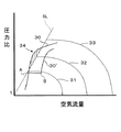
次に、上述したステップS4におけるサージング領域進入判定処理、及びステップS5におけるサージング回避制御の詳細について図4〜図6を参照しながら説明する。図4は、横軸に空気流量、縦軸に電動コンプレッサ3前後の圧力比をとり、電動コンプレッサ3の空気流量性能を示したものである。線図30は、電動コンプレッサ3を作動させた場合の過給特性を示している。一般に圧力に対してコンプレッサに供給されるべき空気流量が少ないとサージングが発生する。破線SLはサージ限界を示し、これよりも左側の領域がサージング領域である。また、線図31、32、及び33は電動コンプレッサの回転数が一定の場合の圧力比の曲線である。線図31から33に向かって回転数は高くなる。この図に示したように、例えば、低速運転中に急加速を検知して電動コンプレッサ3を出力を最大とした場合、圧力比が急上昇しても電動コンプレッサ3に供給されるべき空気流量が不足して斜線34に示したようにサージング領域に進入してしまう。電動コンプレッサ3がサージング領域に進入すると、振動が発生し最悪の場合にはコンプレッサのインペラが破壊する等の危険を招く。
Next, details of the surging region entry determination process in step S4 and the surging avoidance control in step S5 will be described with reference to FIGS. FIG. 4 shows the air flow performance of the
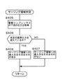
そこで、本実施形態に係る過給システムでは、上記したようにサージング領域への進入又はそのおそれがあるか否かを判定する。図5は、サージング領域進入判定処理の一例を示したフローチャートである。この図に示したように、ECU12は、まずステップS401において温度センサ24(図1参照)の出力値を参照し、電動コンプレッサ3の下流の吸気温度を取得する。次に、ステップS402において、ECU12はこの温度が所定の限界温度を超えているか否かを判定する。この所定の限界温度は予め実験的に定めておき、ECU12のROMに記憶しておけばよい。電動コンプレッサ3の下流の吸気温度を用いてサージング領域への進入又はそのおそれを判定する理由は次の通りである。
Therefore, in the supercharging system according to the present embodiment, it is determined whether or not there is a risk of entering or surging into the surging area as described above. FIG. 5 is a flowchart showing an example of the surging area entry determination process. As shown in this figure, the
図6は、横軸に電動コンプレッサ3の回転数をとり、電動コンプレッサ3の回転数を上昇させたときの空気流量及び電動コンプレッサ3の下流の温度特性を示したものである。破線35よりも右側がサージング領域である。線図36は空気流量を示し、線図37は下流温度を示している。電動コンプレッサ3の回転数を上昇させて行くと、空気流量及び下流温度はともに上昇する。そして、電動コンプレッサ3がサージング領域に進入すると空気流量は略一定になる一方で、下流の温度は急上昇する。この特性は電動コンプレッサの個体差によらず一般に見受けられる傾向である。従って、サージング領域の近傍38に温度の上限値として限界温度を定めておくとともに、電動コンプレッサ3の下流の吸気温度を監視することにより、サージング領域への進入又はそのおそれを電動コンプレッサ3の個体差に関わらず的確に判定することができる。
FIG. 6 shows the air flow rate and the temperature characteristics downstream of the
従って、図5に示したように、上記ステップS402で肯定判定された場合には、サージング領域への進入又はそのおそれがあると判断され(ステップS403)、図3に示したステップS5においてサージング回避制御が実施される。これにより、ECU12はサージング回避制御手段として機能する。具体的には、ECU12は一時的に電動コンプレッサ3の回転数を下げるように、電気モータ3a(図1参照)を制御する。一方、ステップS402で否定判定された場合には、サージング領域への進入又はそのおそれがないと判断される(ステップS404)。
Therefore, as shown in FIG. 5, if the determination in step S402 is affirmative, it is determined that there is a risk of entering or surging into the surging area (step S403), and surging is avoided in step S5 shown in FIG. Control is implemented. Thereby, ECU12 functions as a surging avoidance control means. Specifically, the
以上説明した第1実施形態によれば、サージング領域を回避しつつ過給アシストを実行することができるので、サージングの発生を防止するために電動コンプレッサ3の出力を低めに抑えて運転する必要がない。従って、電動コンプレッサの能力を十分に引き出して過給アシストを実施することができる。
According to the first embodiment described above, the supercharging assist can be executed while avoiding the surging region. Therefore, it is necessary to operate with the output of the
(第2実施形態)
次に、本発明の過給システムに係る第2実施形態について説明する。本実施形態は、図3に示されたサージング領域進入判定(ステップS4)及びサージング回避制御(ステップS5)の態様が上記第1実施形態と相違する。他の点は第1実施形態と共通するので重複する説明を省略する。図7は、本実施形態に係るサージング進入判定処理を示したフローチャートであり、図8は、本実施形態に係るサージング回避制御の制御ルーチンを示したフローチャートである。
(Second Embodiment)
Next, a second embodiment according to the supercharging system of the present invention will be described. This embodiment is different from the first embodiment in the aspects of the surging region entry determination (step S4) and the surging avoidance control (step S5) shown in FIG. Other points are the same as those in the first embodiment, and thus redundant description is omitted. FIG. 7 is a flowchart showing surging approach determination processing according to the present embodiment, and FIG. 8 is a flowchart showing a control routine of surging avoidance control according to the present embodiment.
図7に示したように、ECU12はステップS405において、圧力センサ23(図1参照)の出力値を参照して、電動コンプレッサ3の下流の圧力を取得する。次に、ECU12は、ステップS406において、ステップS405で取得した圧力が所定の限界圧力を超えているか否かを判定する。この所定の限界圧力は、図4に示した電動コンプレッサ3の性能曲線から予め実験的に定めておき、ECU12のROMに記憶しておけばよい。即ち、サージ限界に至る限界圧力を、電動コンプレッサ3の回転数に応じて予め求めておき、ECU12のROMに記憶しておく。そして、ステップS405で取得した圧力と、電動コンプレッサ3の回転数に対応した限界圧力とを比較して、取得した圧力がこの限界圧力に達しているか否かを判断すればよい。電動コンプレッサ3の回転数は、電気モータ3aから取得することができる。これにより、電動コンプレッサ3がサージ領域へ進入する又はそのおそれがあるか否かを判断することができる。
As shown in FIG. 7, in step S405, the
そして、このステップS406において、否定判定されたときは、サージング領域への進入又はそのおそれがないと判断され(ステップS407)、電動コンプレッサ3による過給アシストが続行される。一方、肯定判定されたときはサージング領域への進入又はそのおそれがあると判断され(ステップS408)、図3のステップS5に進みサージング回避制御が実行される。
If a negative determination is made in step S406, it is determined that there is no risk of entering or surging into the surging area (step S407), and supercharging assistance by the
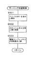
具体的には、図8に示したように、ECU12はステップS501においてバイパス弁7を徐々に開弁する。これにより、電動コンプレッサ3より吐き出された空気はバイパス通路を逆流する(図の矢印の向きと反対向き)。そして、逆流した空気は再び電動コンプレッサ3に吸い上げられることになるので、下流の吸気圧力に対して相対的に空気流量を上げることができる。これにより、図4に示したように、圧力比を略一定にしたままサージング領域への進入を回避することができる(図中A→B)。好ましくは、次のステップS502において、ECU12がスロットル弁8を閉じ側に制御するとよい。これにより、電動コンプレッサ3の上流側の圧力を高めバイパス通路6を逆流した空気を効率よく電動コンプレッサ3に導くことができるので、更に空気流量を上げることができる。
Specifically, as shown in FIG. 8, the
続くステップS503において、電動コンプレッサ3の出力に余裕がある場合にはこの回転数を上昇させる。これにより、図4に示した30’のようにサージング領域を回避しつつ過給圧を高めることができるので、電動コンプレッサ3の能力を十分に引き出すことができる。
In the subsequent step S503, if there is a margin in the output of the
以上本発明の内燃機関用過給システムについて、第1及び第2実施形態に基づいて説明したが、本発明はこれらに限定されない。例えば、第1及び第2の実施形態においては、本発明の過給システムの適用対象としてディーゼルエンジン1としたが、内燃機関の形式は問わない。従って、本発明を火花点火式のガソリンエンジンに適用してもよいし、他のガソリンエンジンに適用してもよい。
As mentioned above, although the supercharging system for internal combustion engines of this invention was demonstrated based on 1st and 2nd embodiment, this invention is not limited to these. For example, in the first and second embodiments, the
また、第1及び第2実施形態においては、電動コンプレッサ3をターボ過給機2の上流側の吸気管4に設けた構成としたが、例えば、電動コンプレッサ3をターボ過給機2の下流側の吸気管4に設けた構成についても本発明を適用することができる。
In the first and second embodiments, the
2 ターボ過給機
2a コンプレッサ
2b タービン
3 電動コンプレッサ
4 吸気管(吸気通路)
6 バイパス通路
7 バイパス弁(第1の調整弁)
8 スロットル弁(第2の調整弁)
12 ECU
23 圧力センサ(圧力検出手段)
24 温度センサ(温度検出手段)
6
8 Throttle valve (second adjusting valve)
12 ECU
23 Pressure sensor (pressure detection means)
24 Temperature sensor (temperature detection means)
Claims (4)
前記電動コンプレッサがサージングを起こすサージング領域への進入又はそのおそれを判定するサージング領域判定手段と、前記サージング領域判定手段により前記サージング領域へ進入又はそのおそれがあると判定された場合に、前記サージングを回避するように前記電動コンプレッサ及び前記第1の調整弁の少なくとも一方を制御するサージング回避制御手段とを具備することを特徴とする内燃機関用過給システム。 A turbocharger having a compressor and a turbine, an electric compressor provided in an intake passage upstream of the compressor of the turbocharger, a bypass passage bypassing the electric compressor, and provided in the bypass passage, A supercharging system for an internal combustion engine comprising: a first regulating valve that regulates an inflow amount of air into the bypass passage;
A surging area determining means for determining whether or not the electric compressor enters a surging area where surging occurs, and the surging area when the surging area determining means determines that the surging area enters or is likely to enter the surging area. A supercharging system for an internal combustion engine comprising surging avoidance control means for controlling at least one of the electric compressor and the first regulating valve so as to avoid it.
前記サージング領域判定手段は、前記温度検出手段の検出結果が所定の限界温度を超えたことを条件として前記サージング領域へ進入又はそのおそれがあると判定し、
前記サージング回避制御手段は、前記サージング領域判定手段により前記サージング領域への進入又はそのおそれがあると判定された場合には前記電動コンプレッサの回転数を低下させるように該電動コンプレッサを制御することを特徴とする請求項1に記載の内燃機関用過給システム。 Temperature detecting means for detecting or estimating the intake air temperature downstream of the electric compressor;
The surging area determination means determines that the detection result of the temperature detection means has entered or is likely to enter the surging area on the condition that a predetermined limit temperature has been exceeded,
The surging avoidance control means controls the electric compressor so as to reduce the rotation speed of the electric compressor when it is determined by the surging area determination means that the surging area has entered or is likely to enter the surging area. The supercharging system for an internal combustion engine according to claim 1, wherein
前記サージング領域判定手段は、前記圧力検出手段の検出結果が所定の限界圧力を超えたことを条件として前記サージング領域への進入又はそのおそれがあると判定し、
前記サージング回避制御手段は、前記サージング領域判定手段により前記サージング領域への進入又はそのおそれがあると判定された場合には、前記電動コンプレッサに流入する空気流量を上げるように前記第1の調整弁を制御することを特徴とする請求項1に記載の内燃機関用過給システム。 Further comprising pressure detecting means for detecting or estimating the pressure downstream of the electric compressor;
The surging area determination means determines that there is a risk of entering or surging into the surging area on the condition that the detection result of the pressure detection means exceeds a predetermined limit pressure,
The surging avoidance control unit is configured to increase the flow rate of air flowing into the electric compressor when the surging region determination unit determines that the surging region enters or is likely to enter the surging region. The supercharging system for an internal combustion engine according to claim 1, wherein:
前記サージング回避制御手段は、前記サージング領域判定手段により前記サージング領域への進入又はそのおそれがあると判定された場合には、前記電動コンプレッサの上流の吸気圧力が上昇するように前記第2の調整弁を閉じ側に制御することを特徴とする請求項3に記載の内燃機関用過給システム。
A second regulating valve provided in the intake passage upstream of the electric compressor;
The surging avoidance control unit is configured to adjust the second adjustment so that the intake pressure upstream of the electric compressor increases when the surging region determination unit determines that the surging region has entered or is likely to enter the surging region. The supercharging system for an internal combustion engine according to claim 3, wherein the valve is controlled to be closed.
Priority Applications (1)
| Application Number | Priority Date | Filing Date | Title |
|---|---|---|---|
| JP2004006022A JP2005201092A (en) | 2004-01-13 | 2004-01-13 | Supercharge system for internal combustion engine |
Applications Claiming Priority (1)
| Application Number | Priority Date | Filing Date | Title |
|---|---|---|---|
| JP2004006022A JP2005201092A (en) | 2004-01-13 | 2004-01-13 | Supercharge system for internal combustion engine |
Publications (1)
| Publication Number | Publication Date |
|---|---|
| JP2005201092A true JP2005201092A (en) | 2005-07-28 |
Family
ID=34820131
Family Applications (1)
| Application Number | Title | Priority Date | Filing Date |
|---|---|---|---|
| JP2004006022A Pending JP2005201092A (en) | 2004-01-13 | 2004-01-13 | Supercharge system for internal combustion engine |
Country Status (1)
| Country | Link |
|---|---|
| JP (1) | JP2005201092A (en) |
Cited By (6)
| Publication number | Priority date | Publication date | Assignee | Title |
|---|---|---|---|---|
| JP2007291960A (en) * | 2006-04-25 | 2007-11-08 | Toyota Motor Corp | Control device of internal combustion engine with centrifugal compressor |
| JP2013127221A (en) * | 2011-12-19 | 2013-06-27 | Isuzu Motors Ltd | Method and apparatus for controlling internal combustion engine |
| JP2014159810A (en) * | 2013-02-19 | 2014-09-04 | Boeing Co | Air charge system and method for internal combustion engine |
| EP2993329A1 (en) | 2014-09-02 | 2016-03-09 | Toyota Jidosha Kabushiki Kaisha | Internal combustion engine system |
| US9470140B2 (en) | 2011-07-15 | 2016-10-18 | Mitsubishi Heavy Industries, Ltd. | Electric supercharger, assembling method of the same, and internal combustion engine |
| DE102016111692B4 (en) | 2015-07-14 | 2024-02-08 | Ford Global Technologies, Llc | Boost pressure control method |
-
2004
- 2004-01-13 JP JP2004006022A patent/JP2005201092A/en active Pending
Cited By (6)
| Publication number | Priority date | Publication date | Assignee | Title |
|---|---|---|---|---|
| JP2007291960A (en) * | 2006-04-25 | 2007-11-08 | Toyota Motor Corp | Control device of internal combustion engine with centrifugal compressor |
| US9470140B2 (en) | 2011-07-15 | 2016-10-18 | Mitsubishi Heavy Industries, Ltd. | Electric supercharger, assembling method of the same, and internal combustion engine |
| JP2013127221A (en) * | 2011-12-19 | 2013-06-27 | Isuzu Motors Ltd | Method and apparatus for controlling internal combustion engine |
| JP2014159810A (en) * | 2013-02-19 | 2014-09-04 | Boeing Co | Air charge system and method for internal combustion engine |
| EP2993329A1 (en) | 2014-09-02 | 2016-03-09 | Toyota Jidosha Kabushiki Kaisha | Internal combustion engine system |
| DE102016111692B4 (en) | 2015-07-14 | 2024-02-08 | Ford Global Technologies, Llc | Boost pressure control method |
Similar Documents
| Publication | Publication Date | Title |
|---|---|---|
| EP1460247B1 (en) | Control apparatus and control method for internal combustion engine | |
| KR101490959B1 (en) | Control mehtod of turbochager | |
| US6883324B2 (en) | Control apparatus and control method for internal combustion engine | |
| JP4483584B2 (en) | Supercharging system for internal combustion engines | |
| JP2005220761A (en) | Control device for diesel engine | |
| JP6163914B2 (en) | Diesel engine and control method thereof | |
| JP2006266216A (en) | Intake/exhaust device for diesel engine | |
| CN107587947B (en) | Method and system for controlling vehicle supercharger | |
| JP2007092683A (en) | Supercharging device for engine | |
| JP5649343B2 (en) | Intake throttle control method for internal combustion engine | |
| JP2009243268A (en) | Motor driven supercharger control device | |
| JP2007247540A (en) | Method for controlling egr system and egr system | |
| JP4341423B2 (en) | Supercharging system for internal combustion engines | |
| JP4918898B2 (en) | Internal combustion engine | |
| JP4412170B2 (en) | Supercharging system for internal combustion engines | |
| JP2005201092A (en) | Supercharge system for internal combustion engine | |
| JP6112397B2 (en) | Supercharger control device for internal combustion engine | |
| JP6128425B2 (en) | Supercharger control device for internal combustion engine | |
| JP3680537B2 (en) | diesel engine | |
| JP4301024B2 (en) | Supercharging system for internal combustion engines | |
| JP4206934B2 (en) | Supercharging system for internal combustion engines | |
| JP2007278066A (en) | Control device for internal combustion engine | |
| JP2008115792A (en) | Supercharging control device | |
| WO2019087453A1 (en) | Engine system | |
| JP2005188359A (en) | Internal combustion engine with supercharger |
Legal Events
| Date | Code | Title | Description |
|---|---|---|---|
| A621 | Written request for application examination |
Free format text: JAPANESE INTERMEDIATE CODE: A621 Effective date: 20060714 |
|
| A977 | Report on retrieval |
Free format text: JAPANESE INTERMEDIATE CODE: A971007 Effective date: 20081023 |
|
| A131 | Notification of reasons for refusal |
Free format text: JAPANESE INTERMEDIATE CODE: A131 Effective date: 20081028 |
|
| A521 | Written amendment |
Free format text: JAPANESE INTERMEDIATE CODE: A523 Effective date: 20081224 |
|
| A02 | Decision of refusal |
Free format text: JAPANESE INTERMEDIATE CODE: A02 Effective date: 20090127 |