EP3409918A1 - Valve module - Google Patents
Valve module Download PDFInfo
- Publication number
- EP3409918A1 EP3409918A1 EP18171775.2A EP18171775A EP3409918A1 EP 3409918 A1 EP3409918 A1 EP 3409918A1 EP 18171775 A EP18171775 A EP 18171775A EP 3409918 A1 EP3409918 A1 EP 3409918A1
- Authority
- EP
- European Patent Office
- Prior art keywords
- fluid
- stem
- stop valve
- valve disc
- module according
- Prior art date
- Legal status (The legal status is an assumption and is not a legal conclusion. Google has not performed a legal analysis and makes no representation as to the accuracy of the status listed.)
- Granted
Links
Images




Classifications
-
- F—MECHANICAL ENGINEERING; LIGHTING; HEATING; WEAPONS; BLASTING
- F01—MACHINES OR ENGINES IN GENERAL; ENGINE PLANTS IN GENERAL; STEAM ENGINES
- F01D—NON-POSITIVE DISPLACEMENT MACHINES OR ENGINES, e.g. STEAM TURBINES
- F01D17/00—Regulating or controlling by varying flow
- F01D17/10—Final actuators
- F01D17/12—Final actuators arranged in stator parts
- F01D17/14—Final actuators arranged in stator parts varying effective cross-sectional area of nozzles or guide conduits
- F01D17/141—Final actuators arranged in stator parts varying effective cross-sectional area of nozzles or guide conduits by means of shiftable members or valves obturating part of the flow path
- F01D17/145—Final actuators arranged in stator parts varying effective cross-sectional area of nozzles or guide conduits by means of shiftable members or valves obturating part of the flow path by means of valves, e.g. for steam turbines
-
- F—MECHANICAL ENGINEERING; LIGHTING; HEATING; WEAPONS; BLASTING
- F01—MACHINES OR ENGINES IN GENERAL; ENGINE PLANTS IN GENERAL; STEAM ENGINES
- F01D—NON-POSITIVE DISPLACEMENT MACHINES OR ENGINES, e.g. STEAM TURBINES
- F01D21/00—Shutting-down of machines or engines, e.g. in emergency; Regulating, controlling, or safety means not otherwise provided for
-
- F—MECHANICAL ENGINEERING; LIGHTING; HEATING; WEAPONS; BLASTING
- F01—MACHINES OR ENGINES IN GENERAL; ENGINE PLANTS IN GENERAL; STEAM ENGINES
- F01D—NON-POSITIVE DISPLACEMENT MACHINES OR ENGINES, e.g. STEAM TURBINES
- F01D25/00—Component parts, details, or accessories, not provided for in, or of interest apart from, other groups
- F01D25/08—Cooling; Heating; Heat-insulation
- F01D25/10—Heating, e.g. warming-up before starting
-
- F—MECHANICAL ENGINEERING; LIGHTING; HEATING; WEAPONS; BLASTING
- F01—MACHINES OR ENGINES IN GENERAL; ENGINE PLANTS IN GENERAL; STEAM ENGINES
- F01D—NON-POSITIVE DISPLACEMENT MACHINES OR ENGINES, e.g. STEAM TURBINES
- F01D25/00—Component parts, details, or accessories, not provided for in, or of interest apart from, other groups
- F01D25/24—Casings; Casing parts, e.g. diaphragms, casing fastenings
- F01D25/26—Double casings; Measures against temperature strain in casings
-
- F—MECHANICAL ENGINEERING; LIGHTING; HEATING; WEAPONS; BLASTING
- F16—ENGINEERING ELEMENTS AND UNITS; GENERAL MEASURES FOR PRODUCING AND MAINTAINING EFFECTIVE FUNCTIONING OF MACHINES OR INSTALLATIONS; THERMAL INSULATION IN GENERAL
- F16K—VALVES; TAPS; COCKS; ACTUATING-FLOATS; DEVICES FOR VENTING OR AERATING
- F16K1/00—Lift valves or globe valves, i.e. cut-off apparatus with closure members having at least a component of their opening and closing motion perpendicular to the closing faces
- F16K1/32—Details
- F16K1/34—Cutting-off parts, e.g. valve members, seats
-
- F—MECHANICAL ENGINEERING; LIGHTING; HEATING; WEAPONS; BLASTING
- F16—ENGINEERING ELEMENTS AND UNITS; GENERAL MEASURES FOR PRODUCING AND MAINTAINING EFFECTIVE FUNCTIONING OF MACHINES OR INSTALLATIONS; THERMAL INSULATION IN GENERAL
- F16K—VALVES; TAPS; COCKS; ACTUATING-FLOATS; DEVICES FOR VENTING OR AERATING
- F16K1/00—Lift valves or globe valves, i.e. cut-off apparatus with closure members having at least a component of their opening and closing motion perpendicular to the closing faces
- F16K1/32—Details
- F16K1/34—Cutting-off parts, e.g. valve members, seats
- F16K1/44—Details of seats or valve members of double-seat valves
- F16K1/443—Details of seats or valve members of double-seat valves the seats being in series
-
- F—MECHANICAL ENGINEERING; LIGHTING; HEATING; WEAPONS; BLASTING
- F16—ENGINEERING ELEMENTS AND UNITS; GENERAL MEASURES FOR PRODUCING AND MAINTAINING EFFECTIVE FUNCTIONING OF MACHINES OR INSTALLATIONS; THERMAL INSULATION IN GENERAL
- F16K—VALVES; TAPS; COCKS; ACTUATING-FLOATS; DEVICES FOR VENTING OR AERATING
- F16K27/00—Construction of housing; Use of materials therefor
- F16K27/02—Construction of housing; Use of materials therefor of lift valves
-
- F—MECHANICAL ENGINEERING; LIGHTING; HEATING; WEAPONS; BLASTING
- F16—ENGINEERING ELEMENTS AND UNITS; GENERAL MEASURES FOR PRODUCING AND MAINTAINING EFFECTIVE FUNCTIONING OF MACHINES OR INSTALLATIONS; THERMAL INSULATION IN GENERAL
- F16K—VALVES; TAPS; COCKS; ACTUATING-FLOATS; DEVICES FOR VENTING OR AERATING
- F16K3/00—Gate valves or sliding valves, i.e. cut-off apparatus with closing members having a sliding movement along the seat for opening and closing
- F16K3/02—Gate valves or sliding valves, i.e. cut-off apparatus with closing members having a sliding movement along the seat for opening and closing with flat sealing faces; Packings therefor
- F16K3/0227—Packings
-
- F—MECHANICAL ENGINEERING; LIGHTING; HEATING; WEAPONS; BLASTING
- F16—ENGINEERING ELEMENTS AND UNITS; GENERAL MEASURES FOR PRODUCING AND MAINTAINING EFFECTIVE FUNCTIONING OF MACHINES OR INSTALLATIONS; THERMAL INSULATION IN GENERAL
- F16K—VALVES; TAPS; COCKS; ACTUATING-FLOATS; DEVICES FOR VENTING OR AERATING
- F16K3/00—Gate valves or sliding valves, i.e. cut-off apparatus with closing members having a sliding movement along the seat for opening and closing
- F16K3/02—Gate valves or sliding valves, i.e. cut-off apparatus with closing members having a sliding movement along the seat for opening and closing with flat sealing faces; Packings therefor
- F16K3/0281—Guillotine or blade-type valves, e.g. no passage through the valve member
-
- F—MECHANICAL ENGINEERING; LIGHTING; HEATING; WEAPONS; BLASTING
- F16—ENGINEERING ELEMENTS AND UNITS; GENERAL MEASURES FOR PRODUCING AND MAINTAINING EFFECTIVE FUNCTIONING OF MACHINES OR INSTALLATIONS; THERMAL INSULATION IN GENERAL
- F16K—VALVES; TAPS; COCKS; ACTUATING-FLOATS; DEVICES FOR VENTING OR AERATING
- F16K3/00—Gate valves or sliding valves, i.e. cut-off apparatus with closing members having a sliding movement along the seat for opening and closing
- F16K3/30—Details
- F16K3/314—Forms or constructions of slides; Attachment of the slide to the spindle
-
- F—MECHANICAL ENGINEERING; LIGHTING; HEATING; WEAPONS; BLASTING
- F16—ENGINEERING ELEMENTS AND UNITS; GENERAL MEASURES FOR PRODUCING AND MAINTAINING EFFECTIVE FUNCTIONING OF MACHINES OR INSTALLATIONS; THERMAL INSULATION IN GENERAL
- F16K—VALVES; TAPS; COCKS; ACTUATING-FLOATS; DEVICES FOR VENTING OR AERATING
- F16K31/00—Actuating devices; Operating means; Releasing devices
- F16K31/44—Mechanical actuating means
- F16K31/56—Mechanical actuating means without stable intermediate position, e.g. with snap action
-
- F—MECHANICAL ENGINEERING; LIGHTING; HEATING; WEAPONS; BLASTING
- F22—STEAM GENERATION
- F22B—METHODS OF STEAM GENERATION; STEAM BOILERS
- F22B33/00—Steam-generation plants, e.g. comprising steam boilers of different types in mutual association
- F22B33/18—Combinations of steam boilers with other apparatus
-
- F—MECHANICAL ENGINEERING; LIGHTING; HEATING; WEAPONS; BLASTING
- F22—STEAM GENERATION
- F22B—METHODS OF STEAM GENERATION; STEAM BOILERS
- F22B37/00—Component parts or details of steam boilers
- F22B37/02—Component parts or details of steam boilers applicable to more than one kind or type of steam boiler
-
- F—MECHANICAL ENGINEERING; LIGHTING; HEATING; WEAPONS; BLASTING
- F05—INDEXING SCHEMES RELATING TO ENGINES OR PUMPS IN VARIOUS SUBCLASSES OF CLASSES F01-F04
- F05D—INDEXING SCHEME FOR ASPECTS RELATING TO NON-POSITIVE-DISPLACEMENT MACHINES OR ENGINES, GAS-TURBINES OR JET-PROPULSION PLANTS
- F05D2220/00—Application
- F05D2220/30—Application in turbines
- F05D2220/31—Application in turbines in steam turbines
Definitions
- the present invention relates to a valve module including a plurality of valve discs and to a steam turbine and a power generation system including the same.
- a steam turbine plant includes a steam generator, which generates high-pressure steam by heating a working fluid to a high temperature in a boiler.
- the steam pressure generated in the steam generator rotates a turbine, and the rotational force of the turbine rotates an electric generator, thereby producing electric power.
- a steam turbine plant includes a boiler, which generates high-temperature and high-pressure steam using a heat source such as thermal energy or nuclear energy, and a turbine, which generates drive force for driving an electric generator using steam supplied from the boiler.
- the steam turbine plant includes multiple turbines whose operating pressures are different from one another, namely, a high-pressure turbine, a medium-pressure turbine, and a low-pressure turbine.
- the amount of steam generated in the steam generator and supplied to the turbine via a control valve is controlled depending on the pressure of the steam. At this time, the output of the turbine is controlled according to the opening degree of the control valve.
- Such a control valve is typically large and is manufactured in accordance with other large-scale power plant equipment.
- performance testing is carried out while the control valve is installed in a common wind tunnel, whereupon the inlet pressure and the outlet pressure of the control valve are compared with each other.
- the present invention has been made in view of the above problems, and it is an object of the present invention to provide a valve module capable of protecting a stem from high-pressure fluid that is introduced to a stop valve, and a steam turbine and a power generation system including the same.
- a valve module including a stop valve, a control valve, and a case.
- the stop valve may include a stem configured to reciprocate rectilinearly between a first position and a second position, a stop valve disc mounted to an upper portion of the stem and configured to pass fluid when the stem is in the first position and to block fluid flow when the stem is in the second position, and a sealing member surrounding the stem and configured to prevent exposure of the stem when the stop valve disc is located at the first position.
- the control valve may be disposed above the stop valve and configured to control an amount of introduced fluid.
- the case may include a flow space for accommodating the stop valve and the control valve, an inlet port through which fluid is introduced to the flow space, and an outlet port through which fluid in the flow space is discharged.
- the stop valve disc may be disposed, in an upward location, according to vertical movement of the stem into the first position.
- the stop valve disc may be disposed, in a downward location, according to vertical movement of the stem into the second position.
- the sealing member may be formed of a material having greater toughness than a material of the stem.
- the stop valve disc has a bottom side and a receiving recess may be formed in the bottom side to receive the sealing member.
- the sealing member may include a protruding portion extending upward and flaring outward to meet an inward lip formed on an inner circumference of the bottom side of the stop valve disc, when the stem is in the first position.
- the stop valve disc may have an insertion recess formed in the bottom side to receive the protruding portion when the stem is in the second position.
- the inward lip of the stop valve disc may extend from the inner circumference at an inclination angle, and the protruding portion may be formed to have the same inclination angle.
- the protruding portion of the sealing member and the inward lip of the stop valve disc may engage with each other to prevent fluid from entering the receiving recess through the bottom side of the stop valve disc.
- the sealing member may include a guide portion formed at an upper end of the sealing member, and the guide portion may have a concavely curved shape in order to guide fluid in a downward direction when the stop valve disc is located at the first position. Below the guide portion, the sealing member may have an outer diameter that gradually increases in the downward direction.
- the case may include a valve seat on which the stop valve disc is seated in order to block a flow passage of fluid.
- the valve seat may include a convex portion facing the stop valve and an inclined surface formed on the convex portion and inclined downwardly in order to guide fluid introduced into a fluid space formed between the valve seat and the stop valve disc.
- the inclined surface may be inclined at an angle ranging from 40° to 50° with respect to a horizontal line that extends from an upper end of the valve seat.
- the flow space may have an elliptical shape.
- the control valve may include a rod configured to reciprocate rectilinearly in a vertical direction; and a control valve disc mounted to a lower portion of the rod and configured to control an amount of introduced fluid according to movement of the rod.
- the control valve disc may have a bottom side and a receiving recess in which an upper end portion of the stop valve disc and an upper end portion of the stem are received through the bottom side.
- the control valve disc may have a lower portion for guiding introduced fluid in a downward direction and an outer diameter of the lower portion that gradually decreases in the downward direction.
- a steam turbine including a turbine that may include a rotor equipped with a plurality of turbine blades and a turbine housing for accommodating the rotor, the turbine housing having a fluid inlet and a fluid outlet; and the above valve module mounted to the turbine housing.
- a power generation system comprising a boiler configured to heat fluid to a high temperature; a supply pipe connected to the boiler and configured to transfer fluid; and a steam turbine configured to be rotated by fluid supplied thereto via the supply pipe so as to generate drive force.
- the steam turbine may include a turbine and the above valve module mounted to the turbine.
- the power generation system may further include a fluid circulation line configured to circulate fluid discharged from the steam turbine.
- the fluid circulation line may include a first circulation line configured to allow fluid discharged from the steam turbine to undergo heat exchange in a recuperator; a second circulation line configured to allow fluid that has undergone heat exchange in the recuperator to be condensed in an air-cooled condenser; a third circulation line configured to allow fluid condensed in the air-cooled condenser to be compressed by a main pump; a fourth circulation line configured to allow fluid compressed by the main pump to undergo heat exchange in the recuperator; and a fifth circulation line configured to allow fluid that has undergone heat exchange in the recuperator to be reheated in the boiler.
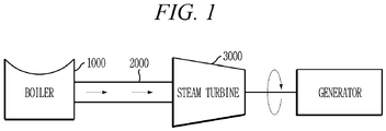
- the power generation system using the steam turbine includes a boiler 1000, a supply pipe 2000, and a steam turbine 3000.
- the boiler 1000 serves to heat fluid to a high temperature.
- the supply pipe 2000 receives the high-pressure fluid from the boiler 1000 and transfers the high-pressure fluid to the steam turbine 3000.
- the steam turbine 3000 is rotated by the high-pressure fluid, which is supplied through the supply pipe 2000, and generates power.
- the power generation system may further include a fluid circulation line 2100.
- the supply pipe 2000 serves to transfer fluid, whose temperature has been raised to about 600°C and pressure has been raised to about 240 bar by the boiler 1000, which generates combustion heat by forcibly receiving fuel as well as combustion air sucked from the outside by a forced draft fan (not shown).
- the fluid transferred through the supply pipe 2000 is introduced into a valve module 3200 mounted on the steam turbine 3000.
- the valve module 3200 selectively passes (allows) or blocks (cuts off) the flow of fluid, specifically the flow of fluid to be introduced to the steam turbine 3000, and controls the pressure of the introduced fluid.
- the steam turbine 3000 is operated by the fluid that has passed through the valve module 3200.
- the exhaust gas discharged from the boiler 1000 is discharged from the system via a stack.
- the fluid may be at least one of water, carbon dioxide (CO 2 ), or supercritical carbon dioxide (SCO 2 ). However, the present invention is not limited thereto.
- the fluid circulation line 2100 includes a first circulation line 2110, a second circulation line 2120, a third circulation line 2130, a fourth circulation line 2140, and a fifth circulation line 2150.
- the fluid discharged from the steam turbine 3000 is transferred to a recuperator R through the first circulation line 2110.
- the fluid discharged from the steam turbine 3000 has a temperature of about 450°C and a pressure of about 80 bar.
- the fluid undergoes heat exchange in the recuperator R, and the temperature of the fluid drops to about 50°C.
- the fluid that has undergone the heat exchange in the recuperator R is transferred to an air-cooled condenser A through the second circulation line 2120.
- the fluid that passes through the air-cooled condenser A is cooled to a temperature of about 20°C by an air-cooling fan (not shown) disposed at a front side of the air-cooled condenser A.
- the fluid condensed in the air-cooled condenser A is transferred to a main pump P through the third circulation line 2130.
- the fluid transferred to the main pump P is compressed by the main pump P, and the pressure of the fluid rises.
- the fluid compressed by the main pump P is transferred to the recuperator R through the fourth circulation line 2140.
- the fluid undergoes heat exchange in the recuperator R, and the temperature of the fluid rises.
- the fluid that has undergone the heat exchange in the recuperator R is transferred to the boiler 1000 through the fifth circulation line 2150.
- the fluid is reheated in the boiler 1000, where its temperature and pressure are brought back up to about 600°C and 240 bar, respectively.
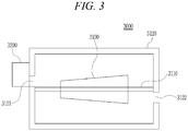
- the steam turbine 3000 includes a turbine 3100 and the valve module 3200.
- the turbine 3100 includes a rotor 3110 and a turbine housing 3120.
- the rotor 3110 is equipped with a plurality of turbine blades (not shown), which are configured to be rotated by a high-pressure fluid.
- the turbine blades are arranged radially inside the turbine housing 3120, and serve to convert the pressure of the fluid, which is introduced into the turbine housing 3120, into rotational motion of the rotor 3110.
- the turbine housing 3120 accommodates the rotor 3110 and includes a fluid inlet 3121, through which a high-pressure fluid is introduced to the turbine housing 3120, and a fluid outlet 3122, through which the fluid that has passed by the turbine blades is discharged from the turbine housing 3120.
- the valve module 3200 is mounted to the fluid inlet 3121 of the turbine housing 3120 and serves to selectively pass or block the flow of fluid and to control the amount (flow rate) of fluid that is introduced to the turbine housing 3120.
- FIG. 4 illustrates the interior of a valve module according to the embodiment of the present invention.
- FIGS. 5 and 7 each show portion "A" of FIG. 4 , when the valve module is in the first- and second-position states, respectively.
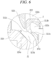
- FIG. 6 is for explaining an inflow angle of fluid introduced to a fluid space formed within the valve module according to the embodiment of the present invention.
- the valve module 3200 includes a stop valve 3210, a control valve 3220, and a case 3230.
- the stop valve 3210 includes a stem 3211, a stop valve disc 3212, and a sealing member 3213.
- the stem 3211 which has one end disposed so as to penetrate a lower portion of the case 3230, is arranged vertically to reciprocate rectilinearly between a first position h1 and a second position h2.
- the stop valve disc 3212 is mounted to an upper portion, and specifically the upper end, of the rectilinearly reciprocating stem 3211 and essentially travels between the first and second positions h1 and h2.
- the stem 3211 may be in the first position h1 or the second position h2, or more correctly, in a state consistent with the first position h1 or the second position h2. Since the stop valve disc 3212 is mounted to the stem 3211, the location of the stop valve disc 3212 may be described as being at the first position h1 or at the second position h2. Therefore, according to the present invention, the stop valve disc 3212 is configured to pass fluid when the stem 3211 is in the first position h1 and to block fluid flow when the stem 3211 is in the second position h2. In other words, the stop valve disc is vertically disposed upward according to movement of the stem 3211 into the first position h1 and is vertically disposed downward according to movement of the stem 3211 into the second position h2.
- the introduction of fluid into the case 3230 is allowed, as the disposition of the stop valve disc 3212 at the first position h1 allows fluid to pass into the case 3230.
- the stop valve disc 3212 is located at the second position h2 due to a vertical movement of the stem 3211, the introduction of fluid into the case 3230 is cut off, as the disposition of the stop valve disc 3212 at the second position h2 blocks fluid flow into the case 3230.
- the sealing member 3213 surrounds the stem 3211 so as to prevent exposure of the stem 3211 when the stop valve disc 3212 is located at the first position h1.
- the sealing member 3213 includes a guide portion 3213b, which has a concavely curved shape. The sealing member 3213 protects the stem 3211 from foreign substances included in the fluid that is introduced into the case 3230.
- the sealing member 3213 may be formed of a material having greater toughness than the material of the stem 3211.
- an additional sealing member (not shown) may be provided between the outer circumferential surface of the upper end of the stem 3211 and the inner circumferential surface of the upper end of the sealing member 3213.
- the control valve 3220 is disposed above the stop valve 3210.
- the control valve 3220 includes a rod 3221 and a control valve disc 3222.
- the rod 3221 which has one end disposed so as to penetrate an upper portion of the case 3230, is arranged vertically and reciprocates rectilinearly.
- the control valve disc 3222 is mounted to a lower portion, and specifically the lower end, of the rod 3221 in order to control the amount of fluid that is introduced according to the reciprocating movement of the rod 3221.
- the control valve disc 3222 has an open bottom side in which a receiving recess 3222a is formed. Upon upward movement of the stem 3211 in the vertical direction, the receiving recess 3222a receives an upper end portion of the stop valve disc 3212 and an upper end portion of the stem 3211 through the open bottom side of the control valve disc 3222.
- the case 3230 includes a flow space 3231, an inlet port 3232, and an outlet port 3233.
- the flow space 3231 accommodates the stop valve 3210 and the control valve 3220 therein.
- the flow space 3231 may have an elliptical shape, which exhibits low pressure loss.
- the inlet port 3232 is connected with the supply pipe 2000, through which high-pressure fluid is introduced into the case 3230.
- the outlet port 3233 serves to discharge the fluid to the fluid inlet 3121 of the turbine housing 3120.
- a valve seat 3234 on which the stop valve disc 3212 is seated in order to block the flow passage of the fluid that is introduced into the case 3230 through the inlet port 3232.
- the control valve disc 3222 has a lower portion for guiding introduced fluid in a downward direction.
- the outer diameter of the lower portion is gradually decreased in the downward direction in order to increase the distance between the outer circumferential surface of the control valve disc 3222 and the valve seat 3234, thereby assuring the smooth flow of fluid and securely guiding the fluid to an inclined surface 3234a of the valve seat 3234.
- the stop valve disc 3212 has an open bottom side in which a receiving recess 3212a is formed. Upon upward movement of the stem 3211 in the vertical direction, the receiving recess 3212a receives an upper end portion of the sealing member 3213 through the open bottom side of the stop valve disc 3212.
- the sealing member 3213 may include a protruding portion 3213a, which extends upward and flares outward, at an incline, from the upper end of the sealing member 3213.
- the protruding portion 3213a engages with the stop valve disc 3212, thereby preventing the fluid from entering the receiving recess 3212a through the open bottom side of the stop valve disc 3212.
- the stop valve disc 3212 may further have an insertion recess 3212b formed in the bottom side of the stop valve disc 3212, the insertion recess 3212b forming an inner surface of the bottom side, and the protruding portion 3213a is inserted into the insertion recess 3212b when the stop valve disc 3212 is located at the second position h2. That is, when the stem 3211 is moved into the second position h2, the insertion recess 3212b of the stop valve disc 3212 receives the protruding portion 3213a of the sealing member 3213, which surrounds the stem 3211 below the stop valve disc 3212.
- the stop valve disc 3212 may further include an inward lip 3212c, which may engage with the protruding portion 3213a to form a seal.
- the inward lip 3212c extends, at an inclination angle, from an inner circumference of the bottom side of the stop valve disc 3212.
- the protruding portion 3213a is formed have the same inclination angle. That is, the protruding portion 3213a of the sealing member 3213 extends upward and flares outward to meet the inward lip 3212c, when the stem 3211 is in the first position h1.
- an inclined surface of the inward lip 3212c extends inwardly to align with an inclined surface of the protruding portion 3213a, which extends outwardly at the same inclination angle. Therefore, since the inclined surfaces are outer surfaces facing the flow space 3231 and are aligned with each other, the fluid introduced into a specific fluid space FS between the valve seat 3234 and the stop valve disc 3212 may flow more smoothly.
- the specific fluid space FS is formed within the valve module 3200, between the valve seat 3234 and the stop valve disc 3212, when stop valve disc 3212 is located at the first position.
- the stop valve disc 3212 may have a flat-bottomed recess S, which is formed in the center of the outer top surface of the stop valve disc 3212 in order to allow the stop valve disc 3212 to be coupled to the stem 3211 via a nut (not shown).
- the sealing member 3213 may include a guide portion 3213b, which has a concavely curved shape.
- the guide portion 3213b is formed at the lower side of the protruding portion 3213a, which is formed at the upper end of the sealing member 3213.
- the guide portion 3213b prevents the fluid from directly striking the sealing member 3213, thereby preventing the sealing member 3213 from being damaged by being struck by foreign substances included in the fluid and preventing high-cycle fatigue of the stem 3211 attributable to vibration that is applied to the stem 3211 due to being directly struck by the fluid.
- the sealing member 3213 may be formed such that, below the guide portion 3213b, the outer diameter of the sealing member 3213 gradually increases in the downward direction.
- the valve seat 3234 may be formed to be convex toward the stop valve 3210 in order to assure the smooth flow of the fluid. That is, the valve seat 3234 has a convex portion facing the stop valve 3210.
- the valve seat 3234 may include an inclined surface 3234a, which is formed in a central portion of the convex portion of the valve seat 3234 and inclined downwardly in order to guide the fluid toward the guide portion 3213b of the sealing member 3213.
- the inclined surface 3234a may be inclined at an angle ⁇ ranging from 40° to 50°, specifically at an angle ⁇ of 45°, with respect to the horizontal line that extends from the upper end of the valve seat 3234.
- An angle ⁇ of less than 40° tends to impede the flow of the introduced fluid (i.e., produces a decreased flow rate), and thus the fluid cannot flow smoothly.
- An angle ⁇ of greater than 50° allows the fluid to flow rapidly and strongly in the downward direction, but the flow for such an angle is excessive and results in the introduced fluid striking the sealing member 3213 more directly, thus applying vibration to the stem 3211.
- the present invention is capable of protecting a stem from foreign substances included in high-pressure fluid that is introduced into a stop valve and of preventing the stem from being damaged by high-cycle fatigue attributable to vibration that is applied to the stem.
Landscapes
- Engineering & Computer Science (AREA)
- General Engineering & Computer Science (AREA)
- Mechanical Engineering (AREA)
- Physics & Mathematics (AREA)
- Thermal Sciences (AREA)
- Lift Valve (AREA)
Abstract
Description
- The present invention relates to a valve module including a plurality of valve discs and to a steam turbine and a power generation system including the same.
- A steam turbine plant includes a steam generator, which generates high-pressure steam by heating a working fluid to a high temperature in a boiler. The steam pressure generated in the steam generator rotates a turbine, and the rotational force of the turbine rotates an electric generator, thereby producing electric power.
- In general, a steam turbine plant includes a boiler, which generates high-temperature and high-pressure steam using a heat source such as thermal energy or nuclear energy, and a turbine, which generates drive force for driving an electric generator using steam supplied from the boiler. In order to improve the operational efficiency, the steam turbine plant includes multiple turbines whose operating pressures are different from one another, namely, a high-pressure turbine, a medium-pressure turbine, and a low-pressure turbine. The amount of steam generated in the steam generator and supplied to the turbine via a control valve is controlled depending on the pressure of the steam. At this time, the output of the turbine is controlled according to the opening degree of the control valve.
- Such a control valve is typically large and is manufactured in accordance with other large-scale power plant equipment. In order to optimally design a control valve, and more specifically to determine in advance the valve's flow rate characteristics according to its opening degree, performance testing is carried out while the control valve is installed in a common wind tunnel, whereupon the inlet pressure and the outlet pressure of the control valve are compared with each other.
[Related Art Document] [Patent Document] Korean Patent Laid-open Publication No.10-2006-0067897 - Therefore, the present invention has been made in view of the above problems, and it is an object of the present invention to provide a valve module capable of protecting a stem from high-pressure fluid that is introduced to a stop valve, and a steam turbine and a power generation system including the same.
- In accordance with an aspect of the present invention, the above and other objects can be accomplished by the provision of a valve module including a stop valve, a control valve, and a case. The stop valve may include a stem configured to reciprocate rectilinearly between a first position and a second position, a stop valve disc mounted to an upper portion of the stem and configured to pass fluid when the stem is in the first position and to block fluid flow when the stem is in the second position, and a sealing member surrounding the stem and configured to prevent exposure of the stem when the stop valve disc is located at the first position. The control valve may be disposed above the stop valve and configured to control an amount of introduced fluid. The case may include a flow space for accommodating the stop valve and the control valve, an inlet port through which fluid is introduced to the flow space, and an outlet port through which fluid in the flow space is discharged.
- The stop valve disc may be disposed, in an upward location, according to vertical movement of the stem into the first position. The stop valve disc may be disposed, in a downward location, according to vertical movement of the stem into the second position.
- The sealing member may be formed of a material having greater toughness than a material of the stem.
- The stop valve disc has a bottom side and a receiving recess may be formed in the bottom side to receive the sealing member.
- The sealing member may include a protruding portion extending upward and flaring outward to meet an inward lip formed on an inner circumference of the bottom side of the stop valve disc, when the stem is in the first position.
- The stop valve disc may have an insertion recess formed in the bottom side to receive the protruding portion when the stem is in the second position.
- The inward lip of the stop valve disc may extend from the inner circumference at an inclination angle, and the protruding portion may be formed to have the same inclination angle.
- When the stem is in the first position, the protruding portion of the sealing member and the inward lip of the stop valve disc may engage with each other to prevent fluid from entering the receiving recess through the bottom side of the stop valve disc.
- The sealing member may include a guide portion formed at an upper end of the sealing member, and the guide portion may have a concavely curved shape in order to guide fluid in a downward direction when the stop valve disc is located at the first position. Below the guide portion, the sealing member may have an outer diameter that gradually increases in the downward direction.
- The case may include a valve seat on which the stop valve disc is seated in order to block a flow passage of fluid. The valve seat may include a convex portion facing the stop valve and an inclined surface formed on the convex portion and inclined downwardly in order to guide fluid introduced into a fluid space formed between the valve seat and the stop valve disc. The inclined surface may be inclined at an angle ranging from 40° to 50° with respect to a horizontal line that extends from an upper end of the valve seat.
- The flow space may have an elliptical shape.
- The control valve may include a rod configured to reciprocate rectilinearly in a vertical direction; and a control valve disc mounted to a lower portion of the rod and configured to control an amount of introduced fluid according to movement of the rod.
- The control valve disc may have a bottom side and a receiving recess in which an upper end portion of the stop valve disc and an upper end portion of the stem are received through the bottom side.
- The control valve disc may have a lower portion for guiding introduced fluid in a downward direction and an outer diameter of the lower portion that gradually decreases in the downward direction.
- In accordance with a further aspect of the present invention, there is provided a steam turbine including a turbine that may include a rotor equipped with a plurality of turbine blades and a turbine housing for accommodating the rotor, the turbine housing having a fluid inlet and a fluid outlet; and the above valve module mounted to the turbine housing.
- In accordance with a further aspect of the present invention, there is provided a power generation system comprising a boiler configured to heat fluid to a high temperature; a supply pipe connected to the boiler and configured to transfer fluid; and a steam turbine configured to be rotated by fluid supplied thereto via the supply pipe so as to generate drive force. The steam turbine may include a turbine and the above valve module mounted to the turbine.
- The power generation system may further include a fluid circulation line configured to circulate fluid discharged from the steam turbine. The fluid circulation line may include a first circulation line configured to allow fluid discharged from the steam turbine to undergo heat exchange in a recuperator; a second circulation line configured to allow fluid that has undergone heat exchange in the recuperator to be condensed in an air-cooled condenser; a third circulation line configured to allow fluid condensed in the air-cooled condenser to be compressed by a main pump; a fourth circulation line configured to allow fluid compressed by the main pump to undergo heat exchange in the recuperator; and a fifth circulation line configured to allow fluid that has undergone heat exchange in the recuperator to be reheated in the boiler.
- The above and other objects, features and other advantages of the present invention will be more clearly understood from the following detailed description taken in conjunction with the accompanying drawings, in which:
-
FIG. 1 is conceptual diagram illustrating a power generation system using a steam turbine according to an embodiment of the present invention; -
FIG. 2 is a system diagram of the power generation system ofFIG. 1 ; -
FIG. 3 is a diagram illustrating the operational concept of the valve module and the steam turbine according to the embodiment of the present invention; -
FIG. 4 is a cutaway view of a valve module according to the embodiment of the present invention; -
FIG. 5 is an enlarged view of portion "A" inFIG. 4 , showing the valve module in a first-position state; -
FIG. 6 is a view for explaining an inflow angle of fluid introduced to a fluid space formed within the valve module according to the embodiment of the present invention; and -
FIG. 7 is an enlarged view of portion "A" inFIG. 4 , showing the valve module in a second-position state. - Since embodiments of the present invention can be variously modified in many different forms, reference will now be made in detail to specific embodiments of the present invention. It is to be understood that the present description is not intended to limit the present invention to those specific embodiments and that the present invention is intended to cover not only the specific embodiments but also various alternatives, modifications, equivalents and other embodiments that may be included within the spirit and scope of the present invention as defined by the appended claims.
- The terminology used herein is for the purpose of describing particular embodiments only and is not intended to be limiting. As used herein, the singular forms are intended to include the plural forms as well, unless the context clearly indicates otherwise. It will be further understood that the terms "comprise", "include", "have", etc., when used in this specification, specify the presence of stated features, integers, steps, operations, elements, components, and/or combinations thereof, but do not preclude the presence or addition of one or more other features, integers, steps, operations, elements, components, and/or combinations thereof.
- Hereinafter, preferred embodiments of the present invention will be described in detail with reference to the accompanying drawings. In the drawings, the same or similar elements are denoted by the same reference numerals even though they are depicted in different drawings. In the following description, a detailed description of known functions and configurations incorporated herein will be omitted when it may make the subject matter of the present invention rather unclear. In the drawings, elements may be exaggerated in size, omitted or schematically illustrated for convenience in description and clarity.
- Referring to
FIG. 1 , the power generation system using the steam turbine according to the embodiment of the present invention includes aboiler 1000, asupply pipe 2000, and asteam turbine 3000. Theboiler 1000 serves to heat fluid to a high temperature. Thesupply pipe 2000 receives the high-pressure fluid from theboiler 1000 and transfers the high-pressure fluid to thesteam turbine 3000. Thesteam turbine 3000 is rotated by the high-pressure fluid, which is supplied through thesupply pipe 2000, and generates power. - Referring to
FIG. 2 , the power generation system may further include afluid circulation line 2100. - The
supply pipe 2000 serves to transfer fluid, whose temperature has been raised to about 600°C and pressure has been raised to about 240 bar by theboiler 1000, which generates combustion heat by forcibly receiving fuel as well as combustion air sucked from the outside by a forced draft fan (not shown). The fluid transferred through thesupply pipe 2000 is introduced into avalve module 3200 mounted on thesteam turbine 3000. Thevalve module 3200 selectively passes (allows) or blocks (cuts off) the flow of fluid, specifically the flow of fluid to be introduced to thesteam turbine 3000, and controls the pressure of the introduced fluid. Thesteam turbine 3000 is operated by the fluid that has passed through thevalve module 3200. The exhaust gas discharged from theboiler 1000 is discharged from the system via a stack. The fluid may be at least one of water, carbon dioxide (CO2), or supercritical carbon dioxide (SCO2). However, the present invention is not limited thereto. - The
fluid circulation line 2100 includes afirst circulation line 2110, asecond circulation line 2120, athird circulation line 2130, afourth circulation line 2140, and afifth circulation line 2150. - The fluid discharged from the
steam turbine 3000 is transferred to a recuperator R through thefirst circulation line 2110. The fluid discharged from thesteam turbine 3000 has a temperature of about 450°C and a pressure of about 80 bar. The fluid undergoes heat exchange in the recuperator R, and the temperature of the fluid drops to about 50°C. - The fluid that has undergone the heat exchange in the recuperator R is transferred to an air-cooled condenser A through the
second circulation line 2120. The fluid that passes through the air-cooled condenser A is cooled to a temperature of about 20°C by an air-cooling fan (not shown) disposed at a front side of the air-cooled condenser A. - The fluid condensed in the air-cooled condenser A is transferred to a main pump P through the
third circulation line 2130. The fluid transferred to the main pump P is compressed by the main pump P, and the pressure of the fluid rises. - The fluid compressed by the main pump P is transferred to the recuperator R through the
fourth circulation line 2140. The fluid undergoes heat exchange in the recuperator R, and the temperature of the fluid rises. - The fluid that has undergone the heat exchange in the recuperator R is transferred to the
boiler 1000 through thefifth circulation line 2150. The fluid is reheated in theboiler 1000, where its temperature and pressure are brought back up to about 600°C and 240 bar, respectively. - Referring to
FIG. 3 , thesteam turbine 3000 according to the embodiment of the present invention includes aturbine 3100 and thevalve module 3200. Theturbine 3100 includes arotor 3110 and aturbine housing 3120. Therotor 3110 is equipped with a plurality of turbine blades (not shown), which are configured to be rotated by a high-pressure fluid. The turbine blades are arranged radially inside theturbine housing 3120, and serve to convert the pressure of the fluid, which is introduced into theturbine housing 3120, into rotational motion of therotor 3110. Theturbine housing 3120 accommodates therotor 3110 and includes afluid inlet 3121, through which a high-pressure fluid is introduced to theturbine housing 3120, and afluid outlet 3122, through which the fluid that has passed by the turbine blades is discharged from theturbine housing 3120. Thevalve module 3200 is mounted to thefluid inlet 3121 of theturbine housing 3120 and serves to selectively pass or block the flow of fluid and to control the amount (flow rate) of fluid that is introduced to theturbine housing 3120. -
FIG. 4 illustrates the interior of a valve module according to the embodiment of the present invention.FIGS. 5 and7 each show portion "A" ofFIG. 4 , when the valve module is in the first- and second-position states, respectively.FIG. 6 is for explaining an inflow angle of fluid introduced to a fluid space formed within the valve module according to the embodiment of the present invention. - As illustrated in
FIGS. 4 to 7 , thevalve module 3200 according to the embodiment of the present invention includes astop valve 3210, acontrol valve 3220, and acase 3230. - The
stop valve 3210 includes astem 3211, astop valve disc 3212, and a sealingmember 3213. Thestem 3211, which has one end disposed so as to penetrate a lower portion of thecase 3230, is arranged vertically to reciprocate rectilinearly between a first position h1 and a second position h2. Thestop valve disc 3212 is mounted to an upper portion, and specifically the upper end, of therectilinearly reciprocating stem 3211 and essentially travels between the first and second positions h1 and h2. - Thus, according to an operation of the
valve module 3200, and specifically, the reciprocating operation of thestem 3211, thestem 3211 may be in the first position h1 or the second position h2, or more correctly, in a state consistent with the first position h1 or the second position h2. Since thestop valve disc 3212 is mounted to thestem 3211, the location of thestop valve disc 3212 may be described as being at the first position h1 or at the second position h2. Therefore, according to the present invention, thestop valve disc 3212 is configured to pass fluid when thestem 3211 is in the first position h1 and to block fluid flow when thestem 3211 is in the second position h2. In other words, the stop valve disc is vertically disposed upward according to movement of thestem 3211 into the first position h1 and is vertically disposed downward according to movement of thestem 3211 into the second position h2. - When the
stop valve disc 3212 is located at the first position h1 due to a vertical movement of thestem 3211, the introduction of fluid into thecase 3230 is allowed, as the disposition of thestop valve disc 3212 at the first position h1 allows fluid to pass into thecase 3230. When thestop valve disc 3212 is located at the second position h2 due to a vertical movement of thestem 3211, the introduction of fluid into thecase 3230 is cut off, as the disposition of thestop valve disc 3212 at the second position h2 blocks fluid flow into thecase 3230. - The sealing
member 3213 surrounds thestem 3211 so as to prevent exposure of thestem 3211 when thestop valve disc 3212 is located at the first position h1. The sealingmember 3213 includes aguide portion 3213b, which has a concavely curved shape. The sealingmember 3213 protects thestem 3211 from foreign substances included in the fluid that is introduced into thecase 3230. - In order to assure smooth reciprocating movement of the
stem 3211, which is surrounded by the sealingmember 3213, and to prevent abrasion between thestem 3211 and the sealingmember 3213, nitriding treatment may be performed on the surface of thestem 3211. In addition, the sealingmember 3213 may be formed of a material having greater toughness than the material of thestem 3211. In order to prevent foreign substances from entering a gap between thestem 3211 and the sealingmember 3213, an additional sealing member (not shown) may be provided between the outer circumferential surface of the upper end of thestem 3211 and the inner circumferential surface of the upper end of the sealingmember 3213. - The
control valve 3220 is disposed above thestop valve 3210. Thecontrol valve 3220 includes arod 3221 and acontrol valve disc 3222. Therod 3221, which has one end disposed so as to penetrate an upper portion of thecase 3230, is arranged vertically and reciprocates rectilinearly. Thecontrol valve disc 3222 is mounted to a lower portion, and specifically the lower end, of therod 3221 in order to control the amount of fluid that is introduced according to the reciprocating movement of therod 3221. Thecontrol valve disc 3222 has an open bottom side in which areceiving recess 3222a is formed. Upon upward movement of thestem 3211 in the vertical direction, the receivingrecess 3222a receives an upper end portion of thestop valve disc 3212 and an upper end portion of thestem 3211 through the open bottom side of thecontrol valve disc 3222. - The
case 3230 includes aflow space 3231, aninlet port 3232, and anoutlet port 3233. Theflow space 3231 accommodates thestop valve 3210 and thecontrol valve 3220 therein. Theflow space 3231 may have an elliptical shape, which exhibits low pressure loss. Theinlet port 3232 is connected with thesupply pipe 2000, through which high-pressure fluid is introduced into thecase 3230. Theoutlet port 3233 serves to discharge the fluid to thefluid inlet 3121 of theturbine housing 3120. Inside thecase 3230 is provided avalve seat 3234 on which thestop valve disc 3212 is seated in order to block the flow passage of the fluid that is introduced into thecase 3230 through theinlet port 3232. - The
control valve disc 3222 has a lower portion for guiding introduced fluid in a downward direction. The outer diameter of the lower portion is gradually decreased in the downward direction in order to increase the distance between the outer circumferential surface of thecontrol valve disc 3222 and thevalve seat 3234, thereby assuring the smooth flow of fluid and securely guiding the fluid to aninclined surface 3234a of thevalve seat 3234. - The
stop valve disc 3212 has an open bottom side in which areceiving recess 3212a is formed. Upon upward movement of thestem 3211 in the vertical direction, the receivingrecess 3212a receives an upper end portion of the sealingmember 3213 through the open bottom side of thestop valve disc 3212. - In order to seal off (close) the open bottom side of the
stop valve disc 3212 when thestop valve disc 3212 is located at the first position h1, the sealingmember 3213 may include a protrudingportion 3213a, which extends upward and flares outward, at an incline, from the upper end of the sealingmember 3213. The protrudingportion 3213a engages with thestop valve disc 3212, thereby preventing the fluid from entering the receivingrecess 3212a through the open bottom side of thestop valve disc 3212. Thestop valve disc 3212 may further have aninsertion recess 3212b formed in the bottom side of thestop valve disc 3212, theinsertion recess 3212b forming an inner surface of the bottom side, and the protrudingportion 3213a is inserted into theinsertion recess 3212b when thestop valve disc 3212 is located at the second position h2. That is, when thestem 3211 is moved into the second position h2, theinsertion recess 3212b of thestop valve disc 3212 receives the protrudingportion 3213a of the sealingmember 3213, which surrounds thestem 3211 below thestop valve disc 3212. - The
stop valve disc 3212 may further include aninward lip 3212c, which may engage with the protrudingportion 3213a to form a seal. Theinward lip 3212c extends, at an inclination angle, from an inner circumference of the bottom side of thestop valve disc 3212. The protrudingportion 3213a is formed have the same inclination angle. That is, the protrudingportion 3213a of the sealingmember 3213 extends upward and flares outward to meet theinward lip 3212c, when thestem 3211 is in the first position h1. In other words, when thestop valve disc 3212 is located at the first position h1, an inclined surface of theinward lip 3212c extends inwardly to align with an inclined surface of the protrudingportion 3213a, which extends outwardly at the same inclination angle. Therefore, since the inclined surfaces are outer surfaces facing theflow space 3231 and are aligned with each other, the fluid introduced into a specific fluid space FS between thevalve seat 3234 and thestop valve disc 3212 may flow more smoothly. Here, the specific fluid space FS is formed within thevalve module 3200, between thevalve seat 3234 and thestop valve disc 3212, whenstop valve disc 3212 is located at the first position. - The
stop valve disc 3212 may have a flat-bottomed recess S, which is formed in the center of the outer top surface of thestop valve disc 3212 in order to allow thestop valve disc 3212 to be coupled to thestem 3211 via a nut (not shown). - The sealing
member 3213 may include aguide portion 3213b, which has a concavely curved shape. Theguide portion 3213b is formed at the lower side of the protrudingportion 3213a, which is formed at the upper end of the sealingmember 3213. When thestop valve disc 3212 is located at the first position h1, the fluid introduced into the specific fluid space FS is guided toward theoutlet port 3233 of thecase 3230 at a high speed along the curved surface of the sealingmember 3213. Theguide portion 3213b prevents the fluid from directly striking the sealingmember 3213, thereby preventing the sealingmember 3213 from being damaged by being struck by foreign substances included in the fluid and preventing high-cycle fatigue of thestem 3211 attributable to vibration that is applied to thestem 3211 due to being directly struck by the fluid. - The sealing
member 3213 may be formed such that, below theguide portion 3213b, the outer diameter of the sealingmember 3213 gradually increases in the downward direction. Through this configuration of the sealingmember 3213, when the fluid introduced into the specific fluid space FS flows along theguide portion 3213b, the flow of fluid is expanded radially in the downward direction, and consequently, the fluid is smoothly discharged through theoutlet port 3233 of thecase 3230. - As illustrated in
FIG. 6 , thevalve seat 3234 may be formed to be convex toward thestop valve 3210 in order to assure the smooth flow of the fluid. That is, thevalve seat 3234 has a convex portion facing thestop valve 3210. Thevalve seat 3234 may include aninclined surface 3234a, which is formed in a central portion of the convex portion of thevalve seat 3234 and inclined downwardly in order to guide the fluid toward theguide portion 3213b of the sealingmember 3213. Theinclined surface 3234a may be inclined at an angle θ ranging from 40° to 50°, specifically at an angle θ of 45°, with respect to the horizontal line that extends from the upper end of thevalve seat 3234. An angle θ of less than 40° tends to impede the flow of the introduced fluid (i.e., produces a decreased flow rate), and thus the fluid cannot flow smoothly. An angle θ of greater than 50° allows the fluid to flow rapidly and strongly in the downward direction, but the flow for such an angle is excessive and results in the introduced fluid striking the sealingmember 3213 more directly, thus applying vibration to thestem 3211. - As is apparent from the above description, the present invention is capable of protecting a stem from foreign substances included in high-pressure fluid that is introduced into a stop valve and of preventing the stem from being damaged by high-cycle fatigue attributable to vibration that is applied to the stem.
- Although the preferred embodiments of the present invention have been disclosed for illustrative purposes, those skilled in the art will appreciate that various modifications, additions and substitutions are possible, without departing from the scope and spirit of the invention as disclosed in the accompanying claims.
Claims (15)
- A valve module comprising:a stop valve (3210) comprisinga stem (3211) configured to reciprocate rectilinearly between a first position (h1) and a second position (h2),a stop valve disc (3212) mounted to an upper portion of the stem (3211) and configured to pass fluid when the stem (3211) is in the first position (h1) and to block fluid flow when the stem (3211) is in the second position (h2), anda sealing member (3213) surrounding the stem (3211) and configured to prevent exposure of the stem (3211) when the stop valve disc (3212) is located at the first position (h1);a control valve (3220) disposed above the stop valve (3210) and configured to control an amount of introduced fluid; anda case (3230) comprising a flow space (3231) for accommodating the stop valve (3210) and the control valve (3220), an inlet port (3232) through which fluid is introduced to the flow space (3231), and an outlet port (3233) through which fluid in the flow space (3231) is discharged.
- The valve module according to claim 1, wherein the stop valve disc (3212) is disposed in an upward location according to vertical movement of the stem (3211) into the first position (h1) and is disposed in a downward location according to vertical movement of the stem (3211) into the second position (h2).
- The valve module according to claim 1 or 2, wherein the sealing member (3213) is formed of a material having greater toughness than a material of the stem (3211).
- The valve module according to any one of claims 1, 2 or 3, wherein the stop valve disc (3212) has a bottom side and a receiving recess formed in the bottom side to receive the sealing member (3213).
- The valve module according to claim 4, wherein the sealing member (3213) comprises a protruding portion (3212a) extending upward and flaring outward to meet an inward lip (3212c) formed on an inner circumference of the bottom side of the stop valve disc (3212), when the stem (3211) is in the first position (h1).
- The valve module according to claim 5, wherein the stop valve disc (3212) has an insertion recess (3212b) formed in the bottom side to receive the protruding portion (3212a) when the stem (3211) is in the second position (h2).
- The valve module according to claim 5 or 6, wherein the inward lip (3212c) of the stop valve disc (3212) extends from the inner circumference at an inclination angle, and the protruding portion (3212a) is formed to have the same inclination angle.
- The valve module according to claim 5, 6 or 7, wherein, when the stem (3211) is in the first position (h1), the protruding portion (3212a) of the sealing member (3213) and the inward lip (3212c) of the stop valve disc (3212) engage with each other to prevent fluid from entering the receiving recess through the bottom side of the stop valve disc (3212).
- The valve module according to any one of the preceding claims, wherein the sealing member (3213) comprises a guide portion (3213b) formed at an upper end of the sealing member (3213), the guide portion (3113b) having a concavely curved shape in order to guide fluid in a downward direction when the stop valve disc (3212) is located at the first position (h1).
- The valve module according to claim 9, wherein, below the guide portion (3213b), the sealing member (3213) has an outer diameter that gradually increases in the downward direction.
- The valve module according to any one of the preceding claims, wherein the case (3230) comprises a valve seat (3234) on which the stop valve disc (3212) is seated in order to block a flow passage of fluid.
- The valve module according to claim 11, wherein the valve seat (3234) comprises a convex portion facing the stop valve (3210) and an inclined surface formed on the convex portion and inclined downwardly in order to guide fluid introduced into a fluid space formed between the valve seat and the stop valve disc (3212).
- The valve module according to any one of the preceding claims, wherein the control valve (3220) comprises:a rod (3221) configured to reciprocate rectilinearly in a vertical direction; anda control valve disc (3222) mounted to a lower portion of the rod (3221) and configured to control an amount of introduced fluid according to movement of the rod (3221).
- The valve module according to claim 13, wherein the control valve disc (3222) has a bottom side and a receiving recess (3222a) in which an upper end portion of the stop valve disc (3212) and an upper end portion of the stem (3211) are received through the bottom side.
- The valve module according to claim 13 or 14, wherein the control valve disc (3212) has a lower portion for guiding introduced fluid in a downward direction and an outer diameter of the lower portion that gradually decreases in the downward direction.
Applications Claiming Priority (1)
| Application Number | Priority Date | Filing Date | Title |
|---|---|---|---|
| KR1020170060335A KR101917028B1 (en) | 2017-05-16 | 2017-05-16 | Valve module and steam turbine and power generation system having the same |
Publications (2)
| Publication Number | Publication Date |
|---|---|
| EP3409918A1 true EP3409918A1 (en) | 2018-12-05 |
| EP3409918B1 EP3409918B1 (en) | 2020-04-15 |
Family
ID=62152422
Family Applications (1)
| Application Number | Title | Priority Date | Filing Date |
|---|---|---|---|
| EP18171775.2A Active EP3409918B1 (en) | 2017-05-16 | 2018-05-11 | Valve module |
Country Status (3)
| Country | Link |
|---|---|
| US (1) | US10480344B2 (en) |
| EP (1) | EP3409918B1 (en) |
| KR (1) | KR101917028B1 (en) |
Families Citing this family (2)
| Publication number | Priority date | Publication date | Assignee | Title |
|---|---|---|---|---|
| CN113357406A (en) * | 2021-05-28 | 2021-09-07 | 北京北重汽轮电机有限责任公司 | Novel medium-pressure main steam regulating valve |
| US20260043339A1 (en) * | 2022-08-12 | 2026-02-12 | Mitsubishi Heavy Industries, Ltd. | Steam valve and power generation system |
Citations (7)
| Publication number | Priority date | Publication date | Assignee | Title |
|---|---|---|---|---|
| US4092214A (en) * | 1975-08-13 | 1978-05-30 | Kraftwerk Union Aktiengesellschaft | Nuclear reactor installation |
| US4238290A (en) * | 1974-06-26 | 1980-12-09 | Kraftwerk Union Aktiengesellschaft | Nuclear reactor installation |
| US5018356A (en) * | 1990-10-10 | 1991-05-28 | Westinghouse Electric Corp. | Temperature control of a steam turbine steam to minimize thermal stresses |
| EP1635097A1 (en) * | 2004-09-08 | 2006-03-15 | Kabushiki Kaisha Toshiba | High temperature steam valve and steam turbine plant |
| KR20060067897A (en) | 2004-12-14 | 2006-06-20 | 보르그워너 인코퍼레이티드 | Turbine flow control valve system |
| DE102011107956A1 (en) * | 2011-07-20 | 2013-01-24 | Voith Patent Gmbh | Guide for guiding valve stem of e.g. outlet valve of steam engine, has lubricant return channel provided outside of aperture in housing and branching, between axial ends of aperture, from aperture that runs along longitudinal axis |
| DE102011116295A1 (en) * | 2011-10-18 | 2013-04-18 | Peter Lischka | Steam engine, has intake valve opening toward vapor chamber, and exhaust valve opening toward working chamber if difference in ambient pressure between working chamber and holes located below piston is very low |
Family Cites Families (11)
| Publication number | Priority date | Publication date | Assignee | Title |
|---|---|---|---|---|
| CH539805A (en) * | 1971-09-24 | 1973-07-31 | Bbc Brown Boveri & Cie | Combined quick-closing and control valve |
| CH584348A5 (en) * | 1975-04-30 | 1977-01-31 | Bbc Brown Boveri & Cie | |
| CH583371A5 (en) * | 1975-04-30 | 1976-12-31 | Bbc Brown Boveri & Cie | |
| JPS5485422A (en) * | 1977-12-21 | 1979-07-07 | Tokyo Shibaura Electric Co | Valve |
| JP2003027904A (en) * | 2001-07-18 | 2003-01-29 | Mitsubishi Heavy Ind Ltd | Steam valve |
| JP4619958B2 (en) | 2006-01-20 | 2011-01-26 | 株式会社東芝 | Steam turbine control valve and steam turbine power plant |
| US9115604B2 (en) * | 2009-11-19 | 2015-08-25 | Ormat Technologies Inc. | Power system |
| KR101431133B1 (en) * | 2013-05-13 | 2014-08-18 | 한국해양과학기술원 | OTEC cycle device that contains the ejector |
| JP6157937B2 (en) | 2013-06-07 | 2017-07-05 | 株式会社東芝 | Valve device and manufacturing method thereof |
| KR101682016B1 (en) * | 2015-03-19 | 2016-12-12 | 두산중공업 주식회사 | Steam Turbine Generating System Having Preheating Member |
| KR101695938B1 (en) | 2016-07-08 | 2017-01-13 | 주식회사 대명 | Globe valve which can be easily taken maintenance |
-
2017
- 2017-05-16 KR KR1020170060335A patent/KR101917028B1/en active Active
-
2018
- 2018-04-11 US US15/950,196 patent/US10480344B2/en active Active
- 2018-05-11 EP EP18171775.2A patent/EP3409918B1/en active Active
Patent Citations (7)
| Publication number | Priority date | Publication date | Assignee | Title |
|---|---|---|---|---|
| US4238290A (en) * | 1974-06-26 | 1980-12-09 | Kraftwerk Union Aktiengesellschaft | Nuclear reactor installation |
| US4092214A (en) * | 1975-08-13 | 1978-05-30 | Kraftwerk Union Aktiengesellschaft | Nuclear reactor installation |
| US5018356A (en) * | 1990-10-10 | 1991-05-28 | Westinghouse Electric Corp. | Temperature control of a steam turbine steam to minimize thermal stresses |
| EP1635097A1 (en) * | 2004-09-08 | 2006-03-15 | Kabushiki Kaisha Toshiba | High temperature steam valve and steam turbine plant |
| KR20060067897A (en) | 2004-12-14 | 2006-06-20 | 보르그워너 인코퍼레이티드 | Turbine flow control valve system |
| DE102011107956A1 (en) * | 2011-07-20 | 2013-01-24 | Voith Patent Gmbh | Guide for guiding valve stem of e.g. outlet valve of steam engine, has lubricant return channel provided outside of aperture in housing and branching, between axial ends of aperture, from aperture that runs along longitudinal axis |
| DE102011116295A1 (en) * | 2011-10-18 | 2013-04-18 | Peter Lischka | Steam engine, has intake valve opening toward vapor chamber, and exhaust valve opening toward working chamber if difference in ambient pressure between working chamber and holes located below piston is very low |
Also Published As
| Publication number | Publication date |
|---|---|
| US20180334919A1 (en) | 2018-11-22 |
| US10480344B2 (en) | 2019-11-19 |
| KR101917028B1 (en) | 2018-11-08 |
| EP3409918B1 (en) | 2020-04-15 |
Similar Documents
| Publication | Publication Date | Title |
|---|---|---|
| US8079802B2 (en) | Gas turbine | |
| EP1573173B3 (en) | Power generation with a centrifugal compressor | |
| US7254949B2 (en) | Turbine with vaned nozzles | |
| US20120121384A1 (en) | Rotor and method for manufacturing a rotor for a turbo machine | |
| NZ539413A (en) | Organic rankine cycle waste heat applications by operating a machine designed as a centrifugal compressor in reverse, as a turbine, using R-245fa | |
| EP3409918B1 (en) | Valve module | |
| US9631514B2 (en) | Axial-flow turbine and power plant including the same | |
| JP2017524088A (en) | Shroud hanger assembly | |
| CN106574556A (en) | Gas turbine | |
| US20200095885A1 (en) | Partial admission operation turbine apparatus for improving efficiency of continuous partial admission operation and method for operating turbine apparatus using same | |
| KR20200045817A (en) | Ring segment and gas turbine having the same | |
| US20170045270A1 (en) | Device and method for converting thermal energy | |
| KR20190097287A (en) | Steam turbine plant | |
| US11053807B2 (en) | Axial flow rotating machine | |
| JP2013079580A (en) | Method of operating combined power generating facility and combined power generating facility | |
| US20180216536A1 (en) | Gas turbine | |
| JP2017115716A (en) | Sealing device | |
| US8821107B2 (en) | Method of modifying a steam turbine | |
| KR101986958B1 (en) | Valve module and steam turbine and power generation system having the same | |
| US9829106B2 (en) | Sealing arrangement for gas turbine transition pieces | |
| KR102703143B1 (en) | Blade fixing assembly, gas turbine comprising it and gas turbine manufacturing method | |
| JP2016017446A (en) | Axial turbine and power plant having the same | |
| JP3958728B2 (en) | Gas turbine combustor structure | |
| CN208040454U (en) | Rotor, steam turbine and prime mover equipment of steam turbine | |
| KR20160059731A (en) | Turbomachinery for supercritical high density working fluid |
Legal Events
| Date | Code | Title | Description |
|---|---|---|---|
| PUAI | Public reference made under article 153(3) epc to a published international application that has entered the european phase |
Free format text: ORIGINAL CODE: 0009012 |
|
| STAA | Information on the status of an ep patent application or granted ep patent |
Free format text: STATUS: REQUEST FOR EXAMINATION WAS MADE |
|
| 17P | Request for examination filed |
Effective date: 20180511 |
|
| AK | Designated contracting states |
Kind code of ref document: A1 Designated state(s): AL AT BE BG CH CY CZ DE DK EE ES FI FR GB GR HR HU IE IS IT LI LT LU LV MC MK MT NL NO PL PT RO RS SE SI SK SM TR |
|
| AX | Request for extension of the european patent |
Extension state: BA ME |
|
| RBV | Designated contracting states (corrected) |
Designated state(s): AL AT BE BG CH CY CZ DE DK EE ES FI FR GB GR HR HU IE IS IT LI LT LU LV MC MK MT NL NO PL PT RO RS SE SI SK SM TR |
|
| GRAP | Despatch of communication of intention to grant a patent |
Free format text: ORIGINAL CODE: EPIDOSNIGR1 |
|
| STAA | Information on the status of an ep patent application or granted ep patent |
Free format text: STATUS: GRANT OF PATENT IS INTENDED |
|
| RIC1 | Information provided on ipc code assigned before grant |
Ipc: F01D 17/14 20060101ALI20191024BHEP Ipc: F16K 31/56 20060101ALI20191024BHEP Ipc: F02B 37/02 20060101AFI20191024BHEP Ipc: F22B 37/02 20060101ALI20191024BHEP Ipc: F16K 3/26 20060101ALI20191024BHEP Ipc: F01D 21/00 20060101ALI20191024BHEP Ipc: F16K 1/44 20060101ALI20191024BHEP |
|
| INTG | Intention to grant announced |
Effective date: 20191113 |
|
| GRAS | Grant fee paid |
Free format text: ORIGINAL CODE: EPIDOSNIGR3 |
|
| GRAA | (expected) grant |
Free format text: ORIGINAL CODE: 0009210 |
|
| STAA | Information on the status of an ep patent application or granted ep patent |
Free format text: STATUS: THE PATENT HAS BEEN GRANTED |
|
| AK | Designated contracting states |
Kind code of ref document: B1 Designated state(s): AL AT BE BG CH CY CZ DE DK EE ES FI FR GB GR HR HU IE IS IT LI LT LU LV MC MK MT NL NO PL PT RO RS SE SI SK SM TR |
|
| REG | Reference to a national code |
Ref country code: CH Ref legal event code: EP |
|
| REG | Reference to a national code |
Ref country code: DE Ref legal event code: R096 Ref document number: 602018003713 Country of ref document: DE |
|
| REG | Reference to a national code |
Ref country code: IE Ref legal event code: FG4D |
|
| REG | Reference to a national code |
Ref country code: AT Ref legal event code: REF Ref document number: 1257551 Country of ref document: AT Kind code of ref document: T Effective date: 20200515 |
|
| REG | Reference to a national code |
Ref country code: NL Ref legal event code: MP Effective date: 20200415 |
|
| REG | Reference to a national code |
Ref country code: LT Ref legal event code: MG4D |
|
| PG25 | Lapsed in a contracting state [announced via postgrant information from national office to epo] |
Ref country code: IS Free format text: LAPSE BECAUSE OF FAILURE TO SUBMIT A TRANSLATION OF THE DESCRIPTION OR TO PAY THE FEE WITHIN THE PRESCRIBED TIME-LIMIT Effective date: 20200815 Ref country code: FI Free format text: LAPSE BECAUSE OF FAILURE TO SUBMIT A TRANSLATION OF THE DESCRIPTION OR TO PAY THE FEE WITHIN THE PRESCRIBED TIME-LIMIT Effective date: 20200415 Ref country code: LT Free format text: LAPSE BECAUSE OF FAILURE TO SUBMIT A TRANSLATION OF THE DESCRIPTION OR TO PAY THE FEE WITHIN THE PRESCRIBED TIME-LIMIT Effective date: 20200415 Ref country code: NL Free format text: LAPSE BECAUSE OF FAILURE TO SUBMIT A TRANSLATION OF THE DESCRIPTION OR TO PAY THE FEE WITHIN THE PRESCRIBED TIME-LIMIT Effective date: 20200415 Ref country code: NO Free format text: LAPSE BECAUSE OF FAILURE TO SUBMIT A TRANSLATION OF THE DESCRIPTION OR TO PAY THE FEE WITHIN THE PRESCRIBED TIME-LIMIT Effective date: 20200715 Ref country code: SE Free format text: LAPSE BECAUSE OF FAILURE TO SUBMIT A TRANSLATION OF THE DESCRIPTION OR TO PAY THE FEE WITHIN THE PRESCRIBED TIME-LIMIT Effective date: 20200415 Ref country code: PT Free format text: LAPSE BECAUSE OF FAILURE TO SUBMIT A TRANSLATION OF THE DESCRIPTION OR TO PAY THE FEE WITHIN THE PRESCRIBED TIME-LIMIT Effective date: 20200817 Ref country code: GR Free format text: LAPSE BECAUSE OF FAILURE TO SUBMIT A TRANSLATION OF THE DESCRIPTION OR TO PAY THE FEE WITHIN THE PRESCRIBED TIME-LIMIT Effective date: 20200716 |
|
| REG | Reference to a national code |
Ref country code: AT Ref legal event code: MK05 Ref document number: 1257551 Country of ref document: AT Kind code of ref document: T Effective date: 20200415 |
|
| PG25 | Lapsed in a contracting state [announced via postgrant information from national office to epo] |
Ref country code: BG Free format text: LAPSE BECAUSE OF FAILURE TO SUBMIT A TRANSLATION OF THE DESCRIPTION OR TO PAY THE FEE WITHIN THE PRESCRIBED TIME-LIMIT Effective date: 20200715 Ref country code: HR Free format text: LAPSE BECAUSE OF FAILURE TO SUBMIT A TRANSLATION OF THE DESCRIPTION OR TO PAY THE FEE WITHIN THE PRESCRIBED TIME-LIMIT Effective date: 20200415 Ref country code: RS Free format text: LAPSE BECAUSE OF FAILURE TO SUBMIT A TRANSLATION OF THE DESCRIPTION OR TO PAY THE FEE WITHIN THE PRESCRIBED TIME-LIMIT Effective date: 20200415 Ref country code: LV Free format text: LAPSE BECAUSE OF FAILURE TO SUBMIT A TRANSLATION OF THE DESCRIPTION OR TO PAY THE FEE WITHIN THE PRESCRIBED TIME-LIMIT Effective date: 20200415 |
|
| PG25 | Lapsed in a contracting state [announced via postgrant information from national office to epo] |
Ref country code: AL Free format text: LAPSE BECAUSE OF FAILURE TO SUBMIT A TRANSLATION OF THE DESCRIPTION OR TO PAY THE FEE WITHIN THE PRESCRIBED TIME-LIMIT Effective date: 20200415 |
|
| REG | Reference to a national code |
Ref country code: DE Ref legal event code: R097 Ref document number: 602018003713 Country of ref document: DE |
|
| PG25 | Lapsed in a contracting state [announced via postgrant information from national office to epo] |
Ref country code: DK Free format text: LAPSE BECAUSE OF FAILURE TO SUBMIT A TRANSLATION OF THE DESCRIPTION OR TO PAY THE FEE WITHIN THE PRESCRIBED TIME-LIMIT Effective date: 20200415 Ref country code: RO Free format text: LAPSE BECAUSE OF FAILURE TO SUBMIT A TRANSLATION OF THE DESCRIPTION OR TO PAY THE FEE WITHIN THE PRESCRIBED TIME-LIMIT Effective date: 20200415 Ref country code: IT Free format text: LAPSE BECAUSE OF FAILURE TO SUBMIT A TRANSLATION OF THE DESCRIPTION OR TO PAY THE FEE WITHIN THE PRESCRIBED TIME-LIMIT Effective date: 20200415 Ref country code: SM Free format text: LAPSE BECAUSE OF FAILURE TO SUBMIT A TRANSLATION OF THE DESCRIPTION OR TO PAY THE FEE WITHIN THE PRESCRIBED TIME-LIMIT Effective date: 20200415 Ref country code: AT Free format text: LAPSE BECAUSE OF FAILURE TO SUBMIT A TRANSLATION OF THE DESCRIPTION OR TO PAY THE FEE WITHIN THE PRESCRIBED TIME-LIMIT Effective date: 20200415 Ref country code: EE Free format text: LAPSE BECAUSE OF FAILURE TO SUBMIT A TRANSLATION OF THE DESCRIPTION OR TO PAY THE FEE WITHIN THE PRESCRIBED TIME-LIMIT Effective date: 20200415 Ref country code: ES Free format text: LAPSE BECAUSE OF FAILURE TO SUBMIT A TRANSLATION OF THE DESCRIPTION OR TO PAY THE FEE WITHIN THE PRESCRIBED TIME-LIMIT Effective date: 20200415 Ref country code: MC Free format text: LAPSE BECAUSE OF FAILURE TO SUBMIT A TRANSLATION OF THE DESCRIPTION OR TO PAY THE FEE WITHIN THE PRESCRIBED TIME-LIMIT Effective date: 20200415 |
|
| PLBE | No opposition filed within time limit |
Free format text: ORIGINAL CODE: 0009261 |
|
| STAA | Information on the status of an ep patent application or granted ep patent |
Free format text: STATUS: NO OPPOSITION FILED WITHIN TIME LIMIT |
|
| PG25 | Lapsed in a contracting state [announced via postgrant information from national office to epo] |
Ref country code: PL Free format text: LAPSE BECAUSE OF FAILURE TO SUBMIT A TRANSLATION OF THE DESCRIPTION OR TO PAY THE FEE WITHIN THE PRESCRIBED TIME-LIMIT Effective date: 20200415 Ref country code: SK Free format text: LAPSE BECAUSE OF FAILURE TO SUBMIT A TRANSLATION OF THE DESCRIPTION OR TO PAY THE FEE WITHIN THE PRESCRIBED TIME-LIMIT Effective date: 20200415 |
|
| REG | Reference to a national code |
Ref country code: BE Ref legal event code: MM Effective date: 20200531 |
|
| 26N | No opposition filed |
Effective date: 20210118 |
|
| PG25 | Lapsed in a contracting state [announced via postgrant information from national office to epo] |
Ref country code: LU Free format text: LAPSE BECAUSE OF NON-PAYMENT OF DUE FEES Effective date: 20200511 |
|
| PG25 | Lapsed in a contracting state [announced via postgrant information from national office to epo] |
Ref country code: IE Free format text: LAPSE BECAUSE OF NON-PAYMENT OF DUE FEES Effective date: 20200511 Ref country code: FR Free format text: LAPSE BECAUSE OF NON-PAYMENT OF DUE FEES Effective date: 20200615 |
|
| PG25 | Lapsed in a contracting state [announced via postgrant information from national office to epo] |
Ref country code: SI Free format text: LAPSE BECAUSE OF FAILURE TO SUBMIT A TRANSLATION OF THE DESCRIPTION OR TO PAY THE FEE WITHIN THE PRESCRIBED TIME-LIMIT Effective date: 20200415 Ref country code: BE Free format text: LAPSE BECAUSE OF NON-PAYMENT OF DUE FEES Effective date: 20200531 |
|
| REG | Reference to a national code |
Ref country code: CH Ref legal event code: PL |
|
| PG25 | Lapsed in a contracting state [announced via postgrant information from national office to epo] |
Ref country code: LI Free format text: LAPSE BECAUSE OF NON-PAYMENT OF DUE FEES Effective date: 20210531 Ref country code: CH Free format text: LAPSE BECAUSE OF NON-PAYMENT OF DUE FEES Effective date: 20210531 |
|
| PG25 | Lapsed in a contracting state [announced via postgrant information from national office to epo] |
Ref country code: TR Free format text: LAPSE BECAUSE OF FAILURE TO SUBMIT A TRANSLATION OF THE DESCRIPTION OR TO PAY THE FEE WITHIN THE PRESCRIBED TIME-LIMIT Effective date: 20200415 Ref country code: MT Free format text: LAPSE BECAUSE OF FAILURE TO SUBMIT A TRANSLATION OF THE DESCRIPTION OR TO PAY THE FEE WITHIN THE PRESCRIBED TIME-LIMIT Effective date: 20200415 Ref country code: CY Free format text: LAPSE BECAUSE OF FAILURE TO SUBMIT A TRANSLATION OF THE DESCRIPTION OR TO PAY THE FEE WITHIN THE PRESCRIBED TIME-LIMIT Effective date: 20200415 |
|
| PG25 | Lapsed in a contracting state [announced via postgrant information from national office to epo] |
Ref country code: MK Free format text: LAPSE BECAUSE OF FAILURE TO SUBMIT A TRANSLATION OF THE DESCRIPTION OR TO PAY THE FEE WITHIN THE PRESCRIBED TIME-LIMIT Effective date: 20200415 |
|
| GBPC | Gb: european patent ceased through non-payment of renewal fee |
Effective date: 20220511 |
|
| PG25 | Lapsed in a contracting state [announced via postgrant information from national office to epo] |
Ref country code: GB Free format text: LAPSE BECAUSE OF NON-PAYMENT OF DUE FEES Effective date: 20220511 |
|
| PGFP | Annual fee paid to national office [announced via postgrant information from national office to epo] |
Ref country code: DE Payment date: 20250319 Year of fee payment: 8 |
|
| PGFP | Annual fee paid to national office [announced via postgrant information from national office to epo] |
Ref country code: CZ Payment date: 20250423 Year of fee payment: 8 |