EP3409917A1 - Supercharger and internal combustion engine - Google Patents
Supercharger and internal combustion engine Download PDFInfo
- Publication number
- EP3409917A1 EP3409917A1 EP17760008.7A EP17760008A EP3409917A1 EP 3409917 A1 EP3409917 A1 EP 3409917A1 EP 17760008 A EP17760008 A EP 17760008A EP 3409917 A1 EP3409917 A1 EP 3409917A1
- Authority
- EP
- European Patent Office
- Prior art keywords
- introduction
- flow channel
- outlet
- exhaust gas
- port
- Prior art date
- Legal status (The legal status is an assumption and is not a legal conclusion. Google has not performed a legal analysis and makes no representation as to the accuracy of the status listed.)
- Withdrawn
Links
- 238000002485 combustion reaction Methods 0.000 title claims description 12
- 230000002093 peripheral effect Effects 0.000 claims description 26
- 239000002699 waste material Substances 0.000 description 113
- 230000007246 mechanism Effects 0.000 description 10
- 239000003054 catalyst Substances 0.000 description 8
- 230000004048 modification Effects 0.000 description 6
- 238000012986 modification Methods 0.000 description 6
- 230000004913 activation Effects 0.000 description 4
- 230000007423 decrease Effects 0.000 description 2
- 230000000694 effects Effects 0.000 description 2
- RLQJEEJISHYWON-UHFFFAOYSA-N flonicamid Chemical compound FC(F)(F)C1=CC=NC=C1C(=O)NCC#N RLQJEEJISHYWON-UHFFFAOYSA-N 0.000 description 2
- 238000000034 method Methods 0.000 description 2
- 230000008569 process Effects 0.000 description 2
- 238000005096 rolling process Methods 0.000 description 1
- 238000009751 slip forming Methods 0.000 description 1
Images









Classifications
-
- F—MECHANICAL ENGINEERING; LIGHTING; HEATING; WEAPONS; BLASTING
- F02—COMBUSTION ENGINES; HOT-GAS OR COMBUSTION-PRODUCT ENGINE PLANTS
- F02B—INTERNAL-COMBUSTION PISTON ENGINES; COMBUSTION ENGINES IN GENERAL
- F02B37/00—Engines characterised by provision of pumps driven at least for part of the time by exhaust
- F02B37/12—Control of the pumps
- F02B37/18—Control of the pumps by bypassing exhaust from the inlet to the outlet of turbine or to the atmosphere
- F02B37/183—Arrangements of bypass valves or actuators therefor
-
- F—MECHANICAL ENGINEERING; LIGHTING; HEATING; WEAPONS; BLASTING
- F01—MACHINES OR ENGINES IN GENERAL; ENGINE PLANTS IN GENERAL; STEAM ENGINES
- F01D—NON-POSITIVE DISPLACEMENT MACHINES OR ENGINES, e.g. STEAM TURBINES
- F01D17/00—Regulating or controlling by varying flow
- F01D17/10—Final actuators
- F01D17/105—Final actuators by passing part of the fluid
-
- F—MECHANICAL ENGINEERING; LIGHTING; HEATING; WEAPONS; BLASTING
- F01—MACHINES OR ENGINES IN GENERAL; ENGINE PLANTS IN GENERAL; STEAM ENGINES
- F01D—NON-POSITIVE DISPLACEMENT MACHINES OR ENGINES, e.g. STEAM TURBINES
- F01D17/00—Regulating or controlling by varying flow
- F01D17/10—Final actuators
- F01D17/12—Final actuators arranged in stator parts
- F01D17/14—Final actuators arranged in stator parts varying effective cross-sectional area of nozzles or guide conduits
- F01D17/148—Final actuators arranged in stator parts varying effective cross-sectional area of nozzles or guide conduits by means of rotatable members, e.g. butterfly valves
-
- F—MECHANICAL ENGINEERING; LIGHTING; HEATING; WEAPONS; BLASTING
- F02—COMBUSTION ENGINES; HOT-GAS OR COMBUSTION-PRODUCT ENGINE PLANTS
- F02B—INTERNAL-COMBUSTION PISTON ENGINES; COMBUSTION ENGINES IN GENERAL
- F02B37/00—Engines characterised by provision of pumps driven at least for part of the time by exhaust
- F02B37/02—Gas passages between engine outlet and pump drive, e.g. reservoirs
-
- F—MECHANICAL ENGINEERING; LIGHTING; HEATING; WEAPONS; BLASTING
- F02—COMBUSTION ENGINES; HOT-GAS OR COMBUSTION-PRODUCT ENGINE PLANTS
- F02B—INTERNAL-COMBUSTION PISTON ENGINES; COMBUSTION ENGINES IN GENERAL
- F02B37/00—Engines characterised by provision of pumps driven at least for part of the time by exhaust
- F02B37/02—Gas passages between engine outlet and pump drive, e.g. reservoirs
- F02B37/025—Multiple scrolls or multiple gas passages guiding the gas to the pump drive
-
- F—MECHANICAL ENGINEERING; LIGHTING; HEATING; WEAPONS; BLASTING
- F02—COMBUSTION ENGINES; HOT-GAS OR COMBUSTION-PRODUCT ENGINE PLANTS
- F02B—INTERNAL-COMBUSTION PISTON ENGINES; COMBUSTION ENGINES IN GENERAL
- F02B37/00—Engines characterised by provision of pumps driven at least for part of the time by exhaust
- F02B37/12—Control of the pumps
- F02B37/22—Control of the pumps by varying cross-section of exhaust passages or air passages, e.g. by throttling turbine inlets or outlets or by varying effective number of guide conduits
-
- F—MECHANICAL ENGINEERING; LIGHTING; HEATING; WEAPONS; BLASTING
- F02—COMBUSTION ENGINES; HOT-GAS OR COMBUSTION-PRODUCT ENGINE PLANTS
- F02C—GAS-TURBINE PLANTS; AIR INTAKES FOR JET-PROPULSION PLANTS; CONTROLLING FUEL SUPPLY IN AIR-BREATHING JET-PROPULSION PLANTS
- F02C6/00—Plural gas-turbine plants; Combinations of gas-turbine plants with other apparatus; Adaptations of gas-turbine plants for special use
- F02C6/04—Gas-turbine plants providing heated or pressurised working fluid for other apparatus, e.g. without mechanical power output
- F02C6/10—Gas-turbine plants providing heated or pressurised working fluid for other apparatus, e.g. without mechanical power output supplying working fluid to a user, e.g. a chemical process, which returns working fluid to a turbine of the plant
- F02C6/12—Turbochargers, i.e. plants for augmenting mechanical power output of internal-combustion piston engines by increase of charge pressure
-
- F—MECHANICAL ENGINEERING; LIGHTING; HEATING; WEAPONS; BLASTING
- F02—COMBUSTION ENGINES; HOT-GAS OR COMBUSTION-PRODUCT ENGINE PLANTS
- F02B—INTERNAL-COMBUSTION PISTON ENGINES; COMBUSTION ENGINES IN GENERAL
- F02B37/00—Engines characterised by provision of pumps driven at least for part of the time by exhaust
- F02B37/12—Control of the pumps
- F02B2037/122—Control of rotational speed of the pump
-
- F—MECHANICAL ENGINEERING; LIGHTING; HEATING; WEAPONS; BLASTING
- F02—COMBUSTION ENGINES; HOT-GAS OR COMBUSTION-PRODUCT ENGINE PLANTS
- F02D—CONTROLLING COMBUSTION ENGINES
- F02D9/00—Controlling engines by throttling air or fuel-and-air induction conduits or exhaust conduits
- F02D9/08—Throttle valves specially adapted therefor; Arrangements of such valves in conduits
- F02D9/10—Throttle valves specially adapted therefor; Arrangements of such valves in conduits having pivotally-mounted flaps
- F02D9/1005—Details of the flap
- F02D9/1025—Details of the flap the rotation axis of the flap being off-set from the flap center axis
-
- F—MECHANICAL ENGINEERING; LIGHTING; HEATING; WEAPONS; BLASTING
- F02—COMBUSTION ENGINES; HOT-GAS OR COMBUSTION-PRODUCT ENGINE PLANTS
- F02D—CONTROLLING COMBUSTION ENGINES
- F02D9/00—Controlling engines by throttling air or fuel-and-air induction conduits or exhaust conduits
- F02D9/08—Throttle valves specially adapted therefor; Arrangements of such valves in conduits
- F02D9/12—Throttle valves specially adapted therefor; Arrangements of such valves in conduits having slidably-mounted valve members; having valve members movable longitudinally of conduit
- F02D9/16—Throttle valves specially adapted therefor; Arrangements of such valves in conduits having slidably-mounted valve members; having valve members movable longitudinally of conduit the members being rotatable
-
- F—MECHANICAL ENGINEERING; LIGHTING; HEATING; WEAPONS; BLASTING
- F05—INDEXING SCHEMES RELATING TO ENGINES OR PUMPS IN VARIOUS SUBCLASSES OF CLASSES F01-F04
- F05D—INDEXING SCHEME FOR ASPECTS RELATING TO NON-POSITIVE-DISPLACEMENT MACHINES OR ENGINES, GAS-TURBINES OR JET-PROPULSION PLANTS
- F05D2220/00—Application
- F05D2220/40—Application in turbochargers
-
- Y—GENERAL TAGGING OF NEW TECHNOLOGICAL DEVELOPMENTS; GENERAL TAGGING OF CROSS-SECTIONAL TECHNOLOGIES SPANNING OVER SEVERAL SECTIONS OF THE IPC; TECHNICAL SUBJECTS COVERED BY FORMER USPC CROSS-REFERENCE ART COLLECTIONS [XRACs] AND DIGESTS
- Y02—TECHNOLOGIES OR APPLICATIONS FOR MITIGATION OR ADAPTATION AGAINST CLIMATE CHANGE
- Y02T—CLIMATE CHANGE MITIGATION TECHNOLOGIES RELATED TO TRANSPORTATION
- Y02T10/00—Road transport of goods or passengers
- Y02T10/10—Internal combustion engine [ICE] based vehicles
- Y02T10/12—Improving ICE efficiencies
Definitions
- the present invention relates to a supercharger and an internal combustion engine.
- Turbochargers which are superchargers that perform supercharging of an engine, drive a turbine utilizing exhaust gas.
- the turbochargers have a waste gate mechanism that detours the exhaust gas in order to prevent damage resulting from supercharging pressure becoming too high.
- the waste gate mechanism can cause the exhaust gas to flow to a system exterior without going through the turbine by opening the waste gate valve. Accordingly, the flow rate of the exhaust gas that flows into the turbine can be reduced in accordance with an opening degree of the waste gate valve (refer to Patent Document 1).
- a flap-type waste gate valve is used in many cases.
- Patent Document 1 German Patent Application, Publication No. 10 2013 002 894
- One aspect of the invention has been made in view of the above-described situation, and an object of the invention is to provide a supercharger and an internal combustion engine capable of efficiently utilizing exhaust gas.
- a supercharger including a first introduction part having a first flow channel configured to direct exhaust gas from a first exhaust gas introduction passage that leads to a turbine driven by the exhaust gas; a second introduction part having a second flow channel configured to direct the exhaust gas from a second exhaust gas introduction passage that leads to the turbine; a chamber into which the exhaust gas is introduced through the first flow channel and the second flow channel; an outlet part having one or a plurality of outlet flow channels configured to direct the exhaust gas within the chamber to a system exterior; and a valve member housed in the chamber.
- the chamber has a first introduction port that leads to the first flow channel, a second introduction port that leads to the second flow channel, and one or a plurality of outlet ports that lead to the outlet flow channel.
- a main circulation space that allows gas to circulate thereinto is secured on a main surface side of the valve member within the chamber.
- the valve member is rotatable about an axis, is capable of opening or closing the first introduction port, the second introduction port, and the outlet port in accordance with a rotational position around the axis, and allows two or more opened ports among the first introduction port, the second introduction port, and the outlet port to communicate with each other through the main circulation space.
- valve member allows the first introduction port, and the second introduction port to communicate with each other through the main circulation space.
- valve member allows the first and second introduction ports and the outlet port to communicate with each other through the main circulation space.
- the chamber has an inner peripheral surface that is a cylindrical surface having the axis as a central axis
- the valve member has an outer peripheral surface, which is a columnar surface having the axis as a central axis, as a back surface opposite to the main surface, a cutout, which forms a subsidiary circulation space that allows gas to circulate thereinto, is formed in the outer peripheral surface of the valve member, and the cutout allows any one of the first and second introduction ports and the outlet port to communicate with each other through the subsidiary circulation space.
- valve member allows any one of the first and second introduction ports and the outlet port to communicate with each other through the main circulation spaces, and allows the other of the first and second introduction ports and the outlet port to communicate with each other through the subsidiary circulation space.
- the plurality of outlet ports include a first outlet port and a second outlet port
- the valve member allows any one of the first and second introduction ports and the first outlet port to communicate with each other through the main circulation spaces, and allows the other of the first and second introduction ports and the second outlet port to communicate with each other through the subsidiary circulation space.
- a guide protrusion which is configured to adjust a flow resistance of gas flowing into the outlet port from at least one of the first and second introduction ports, may be formed on the main surface of the valve member.
- An adjustment protrusion which covers a portion of at least any one of the first and second introduction ports and thereby adjusts a flow rate of the gas from the port, may be formed on the main surface of the valve member.
- One aspect of the invention provides an internal combustion engine including a first introduction part having a first flow channel that is configured to direct exhaust gas; a second introduction part having a second flow channel that is configured to direct the exhaust gas; a chamber into which the exhaust gas is introduced through the first flow channel and the second flow channel; an outlet part having one or a plurality of outlet flow channels that is configured to direct the exhaust gas within the chamber to a system exterior; and a valve member housed in the chamber.
- the chamber has a first introduction port that leads to the first flow channel, a second introduction port that leads to the second flow channel, and one or a plurality of outlet ports that lead to the outlet flow channel.
- a main circulation space that allows gas to circulate thereinto is secured on a main surface side of the valve member within the chamber.
- the valve member is rotatable about an axis, is capable of opening or closing the first introduction port, the second introduction port, and the outlet port in accordance with a rotational position around the axis, and allows two or more opened ports among the first introduction port, the second introduction port, and the outlet port to communicate with each other through the main circulation space.
- exhaust gas can be efficiently utilized.
- Superchargers of embodiments are mounted on, for example, vehicles, such as automobiles having a reciprocating engine (hereinafter simply referred to as an engine) serving as an internal combustion engine as a drive source.
- the superchargers are so-called turbochargers that compress intake air utilizing exhaust gas of the engine.
- the engine has one or a plurality of (for example, four) cylinders.
- FIG. 1 is a view showing a basic structure of a supercharger according to a first embodiment.
- the supercharger 1 includes a compressor section 2, a turbine section 3, a bearing section 4, and a waste gate mechanism 5 (rotary valve device).
- the compressor section 2 compresses the intake air introduced from an air cleaner (not shown) to send the compressed air into a cylinder 7 of an engine 6.
- the compressor section 2 includes a compressor wheel 8 and a compressor housing 9.
- the compressor wheel 8 rotates about an axis O1.
- the compressor wheel 8 causes the intake air A flowing in from a direction of an axis O1 to flow due to its centrifugal force while compressing the intake air A from an inner side in a radial direction centered on the axis O1 toward an outer side.
- Compressed air B compressed by the compressor wheel 8 is discharged toward the outer side of the compressor wheel 8 in the radial direction centered on the axis O1.
- the compressor housing 9 includes a wheel housing part 10, a compressor introduction part 11, and a compressor discharge part 12.
- the wheel housing part 10 is covered from the outside in a state where the compressor wheel 8 is rotatable.
- the compressor introduction part 11 communicates with the wheel housing part 10 near a rotation center of the compressor wheel 8.
- the compressor introduction part 11 forms an introduction passage 13 for introducing the intake air A into the wheel housing part 10 in the direction of the axis O1.
- the compressor discharge part 12 communicates with the wheel housing part 10 on the radially outer side of the compressor wheel 8.
- the compressor discharge part 12 is connected to an intake manifold 14.
- the compressor discharge part 12 forms a discharge passage 15 for introducing the compressed air B into the cylinder 7 of the engine 6 via the intake manifold 14.
- the turbine section 3 includes a turbine wheel 16 (turbine) and a turbine housing 17.
- the turbine wheel 16 recovers a portion of heat energy of exhaust gas C discharged from the engine 6 to rotate around an axis O2.
- the turbine housing 17 includes a turbine wheel housing part 19, an exhaust gas introduction part 20, and an exhaust gas discharge part 21.
- the turbine wheel housing part 19 covers the turbine wheel 16 from the outside in a state where the turbine wheel 16 is rotatable.
- the exhaust gas introduction part 20 forms an exhaust gas introduction passage (a passage on a high-pressure side) 20a for introducing the exhaust gas of the engine 6 into the turbine wheel housing part 19.
- the turbine wheel housing part 19 communicates with the exhaust gas introduction part 20 on a radially outer side of the turbine wheel 16.
- the exhaust gas discharge part 21 forms an exhaust gas discharge passage (a passage on a low-pressure side) 21a that communicates with the turbine wheel housing part 19 near a rotation center of the compressor wheel 8.
- the bearing section 4 includes a rotating shaft 18 and a bearing housing (not shown).
- the rotating shaft 18 transmits the rotation of the turbine wheel 16 to the compressor wheel 8.
- the turbine wheel 16 is fixed to a first end part 18a of the rotating shaft 18, and the compressor wheel 8 is fixed to a second end part 18b thereof.
- the bearing housing covers the rotating shaft 18 from the outside.
- the bearing housing has a bearing (not shown) that rotatably supports the rotating shaft 18.
- a bearing for example, a slide bearing, a rolling bearing, or the like is an exemplary example.
- the above-described compressor housing 9 and the above-described turbine housing 17 are fixed to the bearing housing, respectively.
- the waste gate mechanism 5 adjusts the flow rate of the exhaust gas to be supplied toward the turbine wheel 16. In other words, the waste gate mechanism 5 causes an excessive exhaust gas to flow to the exhaust gas discharge part 21 without flowing through the turbine wheel housing part 19.
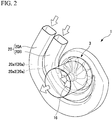
- FIG. 2 is a perspective view showing a schematic configuration of a portion of the supercharger 1.
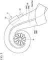
- FIG. 3 is a plan view showing a schematic configuration of a portion of the supercharger 1.
- FIG. 4 is a sectional view schematically showing the supercharger 1, specifically, is a view schematically showing a section orthogonal to an axis of a waste gate valve.
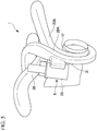
- FIGS. 5 and 6 are perspective views showing a portion of the supercharger 1.
- the exhaust gas introduction part 20 has a first exhaust gas introduction part 20A that is spirally formed and a second exhaust gas introduction part 20B that is spirally formed.
- the first exhaust gas introduction part 20A forms a first exhaust gas introduction passage 20a1.
- the exhaust gas from a first cylinder and a fourth cylinder (not shown) among four engine cylinders is introduced into the first exhaust gas introduction part 20A.
- the second exhaust gas introduction part 20B forms a second exhaust gas introduction passage 20a2.
- the exhaust gas from a second cylinder and a third cylinder (not shown) among the four engine cylinders is introduced into the second exhaust gas introduction part 20B.
- the second exhaust gas introduction part 20B is provided along with the first exhaust gas introduction part 20A on an inner side in a radial direction of the first exhaust gas introduction part 20A (a radial direction of the turbine wheel 16).
- the supercharger 1 is a supercharger a structure in which the two spiral exhaust gas introduction parts 20A and 20B are provided side by side in the radial direction, what is a so-called, "double scroll" type structure.
- the waste gate mechanism 5 includes a first introduction part 31, a second introduction part 32, a chamber 23, a waste gate valve 24 (valve member), and a waste gate outlet part 33 (outlet part).
- the first introduction part 31 forms a first flow channel 31a.
- the first introduction part 31 is connected to the first exhaust gas introduction part 20A and the chamber 23.
- the first introduction part 31 can direct the exhaust gas from the first exhaust gas introduction passage 20a1, to the chamber 23 through the first flow channel 31a.
- the second introduction part 32 forms a second flow channel 32a.
- the second introduction part 32 is connected to the second exhaust gas introduction part 20B and the chamber 23.
- the second introduction part 32 can direct the exhaust gas from the second exhaust gas introduction passage 20a2, to the chamber 23 through the second flow channel 32a.
- the waste gate outlet part 33 forms an outlet flow channel 33a.
- the waste gate outlet part 33 is connected to the chamber 23 and the exhaust gas discharge part 21 (refer to FIG. 1 ).
- the waste gate outlet part 33 can direct the exhaust gas from the chamber 23, to the exhaust gas discharge part 21 through the outlet flow channel 33a.
- the first introduction part 31, the second introduction part 32, a chamber 23, and the waste gate outlet part 33 form a bypass that causes the exhaust gas introduction part 20 and the exhaust gas discharge part 21, which are shown in FIG. 1 , to communicate with each other without going through the turbine wheel housing part 19.
- the chamber 23 is formed in a cylindrical shape that has an axis O3 as a central axis.
- the chamber 23 has a housing space 25 that houses the waste gate valve 24.
- a section of an inner peripheral surface 23a of the chamber 23 orthogonal to the axis O3 is circularly formed. That is, the inner peripheral surface 23a is a cylindrical surface that has the axis O3 as the central axis.
- At least a portion of a section, orthogonal to the axis, of the inner peripheral surface of the chamber, may be formed in a circular-arc shape.
- the chamber 23 has a first introduction port 26, a second introduction port 27, and an outlet port 28.
- the first introduction port 26, the second introduction port 27, and the outlet port 28 are respectively elongated holes that are long in a direction of the axis O3.
- the first introduction port 26, the second introduction port 27, and the outlet port 28 are formed at different positions in a direction around the axis O3.
- the first introduction part 31 is connected to the first introduction port 26. Accordingly, the housing space 25 of the chamber 23 communicates with the first exhaust gas introduction passage 20a1 of the first exhaust gas introduction part 20A through the first introduction port 26 and the first flow channel 31a.
- the second introduction part 32 is connected to the second introduction port 27. Accordingly, the housing space 25 of the chamber 23 communicates with the second exhaust gas introduction passage 20a2 of the second exhaust gas introduction part 20B through the second introduction port 27 and the second flow channel 32a.
- the waste gate outlet part 33 is connected to the outlet port 28. Accordingly, the housing space 25 of the chamber 23 communicates with the exhaust gas discharge passage 21a (refer to FIG. 1 ) of the exhaust gas discharge part 21 through the outlet port 28 and the outlet flow channel 33a.
- the waste gate valve 24 is housed in the housing space 25 of the chamber 23.
- the waste gate valve 24 is supported by the chamber 23 so as to be rotatable around an axis O4.
- the waste gate valve 24 switches communication and non-communication between two or more among the first introduction port 26, the second introduction port 27, and the outlet port 28 as will be described below.
- the chamber 23 functions as a valve casing of the waste gate valve 24.
- FIG. 7 is a perspective view showing the waste gate valve 24. As shown in FIG. 7 , the waste gate valve 24 has a valve body 29 and a driving protruding part 30.
- the valve body 29 is a substantially columnar shape that has the axis O4 as a central axis.
- the external diameter of the valve body 29 is slightly smaller than the internal diameter of the chamber 23.
- a circulation recess 35 is formed at a side part of the valve body 29.
- a space within the circulation recess 35 is referred to as a main circulation space 36.
- a bottom surface of the circulation recess 35 is referred to as a main surface 35a.
- the main surface 35a is a planar surface along the axis O4, and is a surface perpendicular to a radial direction of the valve body 29.
- the main circulation space 36 is a space secured on the main surface 35a side.
- the outer peripheral surface 29a is a surface opposite to the main surface 35a, that is, a back surface.
- the driving protruding part 30 is formed in one end surface 34 out of two end surfaces 34 in a direction of the axis O4 of the valve body 29.
- the driving protruding part 30 protrudes from the end surface 34 along an extension line of the axis O4 of the valve body 29.
- the waste gate valve 24 can be rotated around the axis O4, for example, by driving the driving protruding part 30 with the power of an actuator (not shown).
- FIGS. 8 and 10 are sectional views showing a portion of the supercharger 1.
- the waste gate valve 24 is rotatable around the axis O4, and is able to open or close one or two or more among the first introduction port 26, the second introduction port 27, and the outlet port 28 in accordance with a rotational position around the axis O4.
- the waste gate valve 24 is rotatable around the axis O4, and is able to open or close one or two or more among the first introduction port 26, the second introduction port 27, and the outlet port 28 in accordance with a rotational position around the axis O4.
- the waste gate valve 24 When the waste gate valve 24 is at the first position P1, the first flow channel 31a and the second flow channel 32a are separated from each other. For that reason, the output of the turbine section 3 (refer to FIG. 1 ) during low-speed rotation of the engine 6 can be enhanced.
- the open part of the circulation recess 35 overlaps the first introduction port 26 and the second introduction port 27, and thereby, the first introduction port 26 and the second introduction port 27 are opened. Accordingly, the first introduction port 26 and the second introduction port 27 communicate with each other via the main circulation space 36. For that reason, the first flow channel 31a of the first introduction part 31 and the second flow channel 32a of the second introduction part 32 communicate with each other.
- the outlet port 28 does not overlap the open part of the circulation recess 35 at the second position P2, the outlet port 28 is closed by the outer peripheral surface 29a of the valve body 29. For that reason, the main circulation space 36 does not communicate with the outlet flow channel 33a. Therefore, the exhaust gas within the main circulation space 36 is not discharged from the outlet flow channel 33a.
- the cross-sectional area (in other words, a valve opening degree) of a flow channel that allows the first flow channel 31a and the second flow channel 32a to communicate with each other gradually increases.
- the first flow channel 31a and the second flow channel 32a communicate with each other. Since the flow channels (the first flow channel 31a and the second flow channel 32a) of the two introduction parts (the first introduction part 31 and the second introduction part 32) communicate with each other, the output of the turbine section 3 (refer to FIG. 1 ) during high-speed rotation of the engine 6 can be enhanced.
- the open part of the circulation recess 35 overlaps a portion of the outlet port 28 in addition to the first introduction port 26 and the second introduction port 27.
- the first introduction port 26, the second introduction port 27, and the outlet port 28 are opened.
- the first introduction port 26 and the second introduction port 27 communicate with the outlet port 28 via the main circulation space 36.
- the first flow channel 31a of the first introduction part 31 and the second flow channel 32a of the second introduction part 32 communicate with the outlet flow channel 33a of the waste gate outlet part 33.
- the cross-sectional area (in other words, a valve opening degree) of a flow channel that allows the first flow channel 31a and the second flow channel 32a, and the outlet flow channel 33a to communicate with each other gradually increases.
- the flow channels 31a and 32a and the outlet flow channel 33a communicate with each other in addition to the first flow channel 31a and the second flow channel 32a communicating with each other. For that reason, the exhaust gas within the first exhaust gas introduction passage 20a1 and the second exhaust gas introduction passage 20a2 (refer to FIG. 4 ) can be discharged to a system exterior through the main circulation space 36, the outlet port 28, the outlet flow channel 33a, and the exhaust gas discharge passage 21a. Therefore, it is possible to regulate the output of the turbine section 3 (refer to FIG. 1 ) and adjust supercharging pressure.
- the first flow channel 31a and the second flow channel 32a can be separated from each other by locating the waste gate valve 24 at the first position P1 in a state where the rotational speed of the engine 6 (refer to FIG. 1 ) is low and the flow rate of exhaust gas is low. For that reason, the output of the turbine section 3 (refer to FIG. 1 ) during the low-speed rotation of the engine 6 (refer to FIG. 1 ) can be enhanced.
- the first flow channel 31a and the second flow channel 32a can be caused to communicate with each other by locating the waste gate valve 24 at the second position P2. Accordingly, irrespective of adopting the double scroll type (refer to FIGS. 2 and 3 ), the efficiency of the turbine section 3 can be enhanced when the engine 6 (refer to FIG. 1 ) rotates at a high-speed.
- the waste gate valve 24 can be located at the third position P3, and a portion of exhaust gas can be discharged to the system exterior through the outlet flow channel 33a and the exhaust gas discharge passage 21a (refer to FIG. 1 ). Accordingly, it is possible and thereby adjusts the supercharging pressure, and it is possible to reduce the inlet pressure of the turbine section 3.
- both the communication (refer to FIG. 9 ) between the first flow channel 31a and the second flow channel 32a and the discharge (refer to FIG. 10 ) of exhaust gas are made possible by one waste gate mechanism 5.
- the structure of the device can be simplified, and the size and the cost of the device can be reduced.
- exhaust gas can be used efficiently as described above, though the structure is simple.
- the waste gate valve 24 around the axis O4 within the chamber 23 is used. For that reason, noise accompanying valve opening and closing can be reduced compared to a supercharger using a flap-type waste gate valve. Additionally, since the waste gate valve 24 may open and close ports depending on the rotation around the axis O4, the uneven wear of the waste gate valve 24 is unlikely to occur. The waste gate valve 24 is excellent compared to the flap-type waste gate valve also in terms of the controllability of the valve operation.
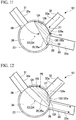
- FIG. 11 is a sectional view schematically showing a portion of a supercharger 101 according to a second embodiment, specifically, is a view schematically showing a section orthogonal to an axis of a waste gate valve 124.
- the same components as those of the previous embodiment will be designated by the same reference signs, and a description thereof will be omitted.
- the supercharger 101 is different from the supercharger 1 of the first embodiment shown in FIG. 8 and the like in that a cutout 130 is formed in an outer peripheral surface 129a of a valve body 129 of the waste gate valve 124.
- the cutout 130 has an inner surface 130a in which a section orthogonal to the axis O4 of the waste gate valve 124 is curvedly recessed.
- the sectional shape of the inner surface 130a is, for example, a circular arc shape, an elliptical arc shape, or the like.
- the sectional shape of the inner surface 130a may not be particularly limited as long as gas is capable of circulate into the cutout 130, and may be a rectangular shape, a V-shape, or the like.
- the cutout 130 is formed in the direction of the axis O4. Gas is capable of circulating through a subsidiary circulation space 131 that is an internal space of the cutout 130.
- the open part of the circulation recess 35 overlaps the first introduction port 26, and a portion of the outlet port 28. For that reason, the first introduction port 26 and a portion of the outlet port 28 are opened by the circulation recess 35. Accordingly, the first introduction port 26 communicates with the outlet port 28 via the main circulation space 36. For that reason, the first flow channel 31a of the first introduction part 31 communicates with the outlet flow channel 33a of the waste gate outlet part 33 via the main circulation space 36.
- the waste gate valve 124 When the waste gate valve 124 is at the second position P5, the first flow channel 31a and the outlet flow channel 33a communicate with each other via the main circulation space 36. Therefore, the exhaust gas within the first exhaust gas introduction passage 20a1 (refer to FIG. 4 ) can be discharged to the system exterior through the first flow channel 31a, the main circulation space 36, the outlet port 28, the outlet flow channel 33a, and the exhaust gas discharge passage 21a (refer to FIG. 1 ). Additionally, since the second flow channel 32a and the outlet flow channel 33a communicate with each other via the subsidiary circulation space 131, the exhaust gas within the second exhaust gas introduction passage 20a2 (refer to FIG. 4 ) can be discharged to the system exterior through the second flow channel 32a, the subsidiary circulation space 131, the outlet port 28, the outlet flow channel 33a, and the exhaust gas discharge passage 21a (refer to FIG. 1 ).
- the exhaust gas from the first flow channel 31a and the second flow channel 32a can be directed to the outlet flow channel 33a in a state where the first introduction port 26 and the second introduction port 27 do not communicate with each other. Accordingly, since the amount of the exhaust gas directed to the outlet flow channel 33a can be increased, it is possible to efficiently heat a catalyst (not shown) on a downstream side and promote activation of the catalyst.
- the open part of the circulation recess 35 overlaps the first introduction port 26 and the second introduction port 27, and thereby, the first introduction port 26 and the second introduction port 27 are opened. Accordingly, the first introduction port 26 and the second introduction port 27 communicate with each other via the main circulation space 36. For that reason, the first flow channel 31a of the first introduction part 31 and the second flow channel 32a of the second introduction part 32 communicate with each other.
- the outlet port 28 is closed by the outer peripheral surface 129a of the valve body 129. For that reason, the main circulation space 36 does not communicate with the outlet flow channel 33a. Therefore, the exhaust gas within the main circulation space 36 is not discharged from the outlet flow channel 33a.
- the waste gate valve 124 when the waste gate valve 124 is at the fourth position P7, the first introduction port 26, the second introduction port 27, and the outlet port 28 are opened by the circulation recess 35. Accordingly, the first introduction port 26 and the second introduction port 27 communicate with the outlet port 28 via the main circulation space 36.
- the flow channels 31a and 32a and the outlet flow channel 33a communicate with each other in addition to the first flow channel 31a and the second flow channel 32a communicating with each other.
- the exhaust gas within the first exhaust gas introduction passage 20a1 and the second exhaust gas introduction passage 20a2 can be discharged to the system exterior through the main circulation space 36, the outlet port 28, the outlet flow channel 33a, and the exhaust gas discharge passage 21a (refer to FIG. 1 ). Therefore, the output of the turbine section 3 during the high-speed rotation of the engine 6 can be enhanced. Moreover, it is possible to regulate the output of the turbine section 3 (refer to FIG. 1 ) and adjust the supercharging pressure.
- the exhaust gas from the first flow channel 31a and the second flow channel 32a can be directed to the outlet flow channel 33a in a state where the first introduction port 26 and the second introduction port 27 do not communicate with each other. Accordingly, since the amount of the exhaust gas directed to the outlet flow channel 33a can be increased, it is possible to efficiently heat a catalyst (not shown) on a downstream side and promote activation of the catalyst.
- FIG. 15 is a sectional view schematically showing a portion of a supercharger 201 according to a third embodiment, specifically, is a view schematically showing a section orthogonal to the axis of the waste gate valve 124.
- the same components as those of the previous embodiment will be designated by the same reference signs, and the description thereof will be omitted.
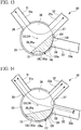
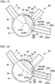
- the supercharger 201 is different from the supercharger 101 of the second embodiment shown in FIG. 11 and the like in that the supercharger 201 includes two waste gate outlet parts 133A and 133B, that is, a first waste gate outlet part 133A and a second waste gate outlet part 133B, instead of the waste gate outlet part 33.
- the first waste gate outlet part 133A is connected to a portion of the outlet port 28 (first outlet port 28A).
- the second waste gate outlet part 133B is connected to the other part (second outlet port 28B) of the outlet port 28.
- the first waste gate outlet part 133A forms a first outlet flow channel 133Aa.
- the second waste gate outlet part 133B forms a second outlet flow channel 133Ba.
- the first outlet flow channel 133Aa and the second outlet flow channel 133Ba are independent from each other.
- the waste gate valve 124 when the waste gate valve 124 is at a first position P8, the first introduction port 26 is opened by the circulation recess 35.
- the second introduction port 27 and the outlet port 28 are closed by the outer peripheral surface 129a of the valve body 129.
- the first introduction port 26 and a portion of the outlet port 28 are opened by the circulation recess 35. Accordingly, the first introduction port 26 communicates with a portion of the outlet port 28 (first outlet port 28A) via the main circulation space 36. For that reason, the first flow channel 31a of the first introduction part 31 communicates with the first outlet flow channel 133Aa of the first waste gate outlet part 133A via the main circulation space 36.
- the second introduction port 27 and the other part (second outlet port 28B) of the outlet port 28 are opened by the cutout 130. Accordingly, the second introduction port 27 communicates with the other part (second outlet port 28B) of the outlet port 28 via the subsidiary circulation space 131. For that reason, the second flow channel 32a of the second introduction part 32 communicates with the second outlet flow channel 133Ba of the second waste gate outlet part 133B via the subsidiary circulation space 131.
- the first introduction port 26 and the second introduction port 27 do not communicate with each other.
- the exhaust gas within the first exhaust gas introduction passage 20a1 (refer to FIG. 4 ) can be discharged to the system exterior through the main circulation space 36, the outlet port 28 (first outlet port 28A), the first outlet flow channel 133Aa, and the exhaust gas discharge passage 21a (refer to FIG. 1 ).
- the second flow channel 32a and the second outlet flow channel 133Ba communicate with each other via the subsidiary circulation space 131, the exhaust gas within the second exhaust gas introduction passage 20a2 (refer to FIG. 4 ) can be discharged to the system exterior through the subsidiary circulation space 131, the outlet port 28 (second outlet port 28B), the second outlet flow channel 133Ba, and the exhaust gas discharge passage 21a (refer to FIG. 1 ).
- the exhaust gas from the first flow channel 31a and the second flow channel 32a can be directed to the outlet flow channels 133Aa and 133Ba in a state where the first introduction port 26 and the second introduction port 27 do not communicate with each other. Since the outlet flow channels 133Aa and 133Ba are independent from each other, a leakage flow between the two the outlet flow channels 133Aa and 133Ba can be prevented, and the discharge amount of exhaust gas can be increased. Therefore, the catalyst (not shown) on the downstream side can be more efficiently heated with the exhaust gas, and activation of the catalyst can be promoted.
- the outlet port 28 is closed by the outer peripheral surface 129a of the valve body 129.
- the waste gate valve 124 when the waste gate valve 124 is at the fourth position P11, the first introduction port 26, the second introduction port 27, and the outlet port 28 are opened by the circulation recess 35. Accordingly, the first introduction port 26 and the second introduction port 27 communicate with the outlet port 28 via the main circulation space 36.
- the flow channels 31a and 32a and the outlet flow channels 133Aa and 133Ba communicate with each other in addition to the first flow channel 31a and the second flow channel 32a communicating with each other.
- the exhaust gas within the first exhaust gas introduction passage 20a1 and the second exhaust gas introduction passage 20a2 can be discharged to the system exterior through the main circulation space 36, the outlet port 28, the outlet flow channels 133Aa and 133Ba, and the exhaust gas discharge passage 21a (refer to FIG. 1 ). Therefore, the output of the turbine section 3 during the high-speed rotation of the engine 6 can be enhanced. Moreover, it is possible to regulate the output of the turbine section 3 (refer to FIG. 1 ) and adjust the supercharging pressure.
- the exhaust gas from the first flow channel 31a and the second flow channel 32a can be respectively directed to the outlet flow channels 133Aa and 133Ba in a state where the first introduction port 26 and the second introduction port 27 do not communicate with each other. Since the outlet flow channels 133Aa and 133Ba are independent from each other, a leakage flow between the two outlet flow channels 133Aa and 133Ba can be prevented, and the discharge amount of exhaust gas can be increased. Therefore, the catalyst (not shown) on the downstream side can be more efficiently heated with the exhaust gas, and activation of the catalyst can be promoted.
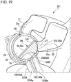
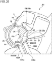
- FIGS. 19 and 20 are sectional views showing a schematic configurations of a portion of a specific example of the supercharger 201.
- the supercharger 201 has the first waste gate outlet part 133A and the second waste gate outlet part 133B.
- the first waste gate outlet part 133A is connected to a portion of the outlet port 28 (first outlet port 28A).
- the second waste gate outlet part 133B is connected to the other part (second outlet port 28B) of the outlet port 28.
- the waste gate valve 124 is at a first position P8 (refer to FIG. 15 ).
- the first introduction port 26 is opened by the circulation recess 35.
- the second introduction port 27 and the outlet port 28 are closed by the outer peripheral surface 129a of the valve body 129.
- the waste gate valve 124 when the waste gate valve 124 is at a second position P9 (refer to FIG. 16 ), the first introduction port 26 and a portion of the outlet port 28 (first outlet port 28A) are opened by the circulation recess 35.
- the second introduction port 27 and the other part (second outlet port 28B) of the outlet port 28 are opened by the cutout 130.
- the first introduction port 26 and the second introduction port 27 do not communicate with each other. For that reason, the first flow channel 31a and the first outlet flow channel 133Aa communicate with each other via the main circulation space 36, and the second flow channel 32a and the second outlet flow channel 133Ba communicate with each other via the subsidiary circulation space 131.
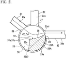
- FIG. 21 is a sectional view schematically showing a waste gate valve 24A that is a first modification example of the waste gate valve 24 of the supercharger 1 according to the first embodiment.
- FIG. 21 is a view showing a section orthogonal to the axis O4.
- FIG. 22 is a perspective view showing the waste gate valve 24A.
- the waste gate valve 24A is different from the waste gate valve 24 shown in FIGS. 7 and 8 in that a guide protrusion 37 is formed on the main surface 35a of a valve body 29A.
- the guide protrusion 37 is formed to protrude from the main surface 35a.
- the guide protrusion 37 has a certain protruding height in the direction of the axis O4.
- a section of the guide protrusion 37 orthogonal to the axis O4 has a shape of which the height gradually decreases from a peak 37a toward both side edges 35a1 and 35a2 of the main surface 35a.
- a surface ranging from a ridgeline 37b including the peak 37a of the guide protrusion 37 to one side edge 35a1 of the main surface 35a is referred to as a guide surface 38.
- the guide surface 38 is a surface in which a section orthogonal to the axis O4 is curvedly recessed.
- the sectional shape of the guide surface 38 is, for example, a circular arc shape, an elliptical arc shape, or the like.
- the position (circumferential position) of the waste gate valve 24A around the axis O4 is a position where the first introduction port 26, the second introduction port 27, and the outlet port 28 are opened by the circulation recess 35.
- the waste gate valve 24A is inclined with respect to a radial direction of the guide surface 38.
- an inclination direction of the guide surface 38 of the waste gate valve 24A is a direction approaching the outlet port 28 while a protruding height of the guide surface 38 with respect to the main surface 35a is reduced outward in the radial direction.
- the exhaust gas which has flowed into the main circulation space 36 from the first introduction port 26 and the second introduction port 27, flows toward the outlet port 28 while being influenced by the guide surface 38 of the guide protrusion 37.
- the flow resistance of exhaust gas becomes small and the exhaust gas smoothly flows toward the outlet port 28.
- the guide protrusion 37 also affects the flow resistance of the exhaust gas that flows into the outlet port 28 from the second introduction port 27.
- the guide protrusion 37 can adjust the flow resistance of the exhaust gas that flows into the outlet port 28 from at least one of the first introduction port 26 and the second introduction port 27. Therefore, the flow rate of the exhaust gas that flows in from the first introduction port 26, the flow rate of the exhaust gas that flows in from the second introduction port 27, and the ratio of the flow rates can be adjusted.
- FIG. 23 is a perspective view showing a waste gate valve 24B that is a second modification example of the waste gate valve 24 of the supercharger 1 according to the first embodiment.
- a guide protrusion 37B is formed on a valve body 29B.
- the waste gate valve 24B is different from the waste gate valve 24A shown in FIG. 22 in that the protruding height of the guide protrusion 37B gradually decreases in one direction along the axis O4.
- the waste gate valve 24B can adjust the effect of arranging the flow of exhaust gas in accordance with the shape of the guide protrusion 37B.
- FIG. 24 is a sectional view showing a supercharger having a waste gate valve 24C that is a third modification example of the waste gate valve 24 of the supercharger 1 according to the first embodiment.
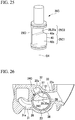
- FIG. 25 is a perspective view showing a waste gate valve 24C.
- FIG. 26 is a sectional view showing a supercharger having the waste gate valve 24C, and is an I-I sectional view of FIG. 24 .
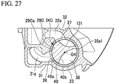
- FIG. 27 is a sectional view showing a supercharger having the waste gate valve 24C, and is an II-II sectional view of FIG. 24 .
- the waste gate valve 24C is different from the waste gate valve 24 shown in FIGS. 7 and 8 in that an adjustment protrusion 40 is formed on the main surface 35a of a valve body 29C.
- the adjustment protrusion 40 is formed in a region including a portion in a length direction (a direction along the axis O4), specifically, one end part in a direction along the axis O4, in the main surface 35a.
- a section of the adjustment protrusion 40 orthogonal to the axis O4 has a shape having a circular-arc outer peripheral surface 40a and a curvedly recessed inner surface 40b.
- the outer peripheral surface 40a is a columnar surface having the axis O4 as a central axis, and is continuously formed from an outer peripheral surface 29Ca of the valve body 29C.
- the inner surface 40b has a shape of which the height is gradually increased from one side edge 35a1 of the main surface 35a toward the other side edge thereof.
- the inner surface 40b is a surface in which a section orthogonal to the axis O4 is curvedly recessed.
- the sectional shape of the inner surface 40b is, for example, a circular arc shape, an elliptical arc shape, or the like.
- a portion in which the adjustment protrusion 40 is formed is referred to as a first portion 29C1
- a portion in which the adjustment protrusion 40 is not formed is referred to as a second portion 29C2.
- the waste gate valve 24C can take a position where, in the second portion 29C2, the first introduction port 26 communicate with the outlet port 28 via the main circulation space 36 and the second introduction port 27 communicates with the outlet port 28 via the subsidiary circulation space 131.
- the outer peripheral surface 40a of the adjustment protrusion 40 covers a portion of the first introduction port 26. For that reason, the inflow rate of the gas from the first introduction port 26 to the chamber 23 (main circulation space 36) can be adjusted.
- the waste gate valve 24C can adjust the inflow rate of the gas from the second introduction port 27 to the chamber 23 (main circulation space 36) if the waste gate valve 24C is disposed at a position where the outer peripheral surface 40a of the adjustment protrusion 40 covers a portion of the second introduction port 27.
- the adjustment protrusion can also be formed so as to be capable of covering portions of both the first introduction port and the second introduction port. According to this configuration, the inflow rate of the gas from the first introduction port and the second introduction port to the chamber can be adjusted.
- FIG. 28 is a perspective view showing a schematic configuration of a portion of a supercharger 301 according to a fourth embodiment.
- An exhaust gas introduction part 320 of the supercharger 301 has a first exhaust gas introduction part 320A that is spirally formed and a second exhaust gas introduction part 320B that is spirally formed.
- the first exhaust gas introduction part 320A and the second exhaust gas introduction part 320B are provided side by side in an axial direction (an axial direction of the turbine wheel 16).
- the supercharger 301 is a supercharger having a structure in which the two spiral exhaust gas introduction parts 320A and 320B are provided side by side in the axial direction, what is so called, a "twin scroll" type structure.
- the supercharger 301 can be provided with the waste gate mechanism 5 (refer to FIG. 1 ), similar to the supercharger 1 (refer to FIG. 2 ).
- the waste gate mechanism 5 for example, the first introduction part 31 (refer to FIG. 4 ) is connected to the first exhaust gas introduction part 320A, and the second introduction part 32 (refer to FIG. 4 ) is connected to the second exhaust gas introduction part 320B.
- FIG. 29 is a view showing a schematic configuration of a portion of an internal combustion engine 400 according to the embodiment.
- the internal combustion engine 400 includes an engine 406, a first introduction part 431, a second introduction part 432, the chamber 23, a valve 24 (valve member), a waste gate outlet part 433, and a supercharger 401.
- the first introduction part 431 forms a first flow channel 431a.
- a first introduction pipeline 441 and a fourth introduction pipeline 444 are connected to the first introduction part 431.
- a first cylinder (not shown) among four cylinders of the engine 406 is connected to the first introduction pipeline 441, and a fourth cylinder (not shown) is connected to the fourth introduction pipeline 444.
- the second introduction part 432 forms a second flow channel 432a.
- a second introduction pipeline 442 and a third introduction pipeline 443 are connected to the second introduction part 432.
- a second cylinder (not shown) among the four cylinders of the engine 406 is connected to the second introduction pipeline 442, and a third cylinder (not shown) is connected to the third introduction pipeline 443.
- the waste gate outlet part 433 forms an outlet flow channel 433a.
- the internal combustion engine 400 can discharge the exhaust gas, which is directed through the first flow channel 431a and the second flow channel 432a from the engine 406, to the system exterior through the chamber 23 and the outlet flow channel 433a.
- the flow of the exhaust gas can be adjusted by disposing the valve 24 to any among the first position P1 (to refer to FIG. 8 ), the second position P2 (to refer to FIG. 9 ), and the third position P3 (to refer to FIG. 10 ).
- the supercharger 1 shown in FIG. 4 and the like has two introduction parts (the first introduction part 31 and the second introduction part 32).
- the number of introduction parts may be two or more arbitrary numbers.
- the first introduction port 26 is capable of communicating with the outlet port 28 via the main circulation space 36
- the second introduction port 27 is capable of communicating the outlet port 28 via the subsidiary circulation space 131.
- the first introduction port is capable of communicating with the outlet port via the subsidiary circulation space 131
- the second introduction port is capable of communicating with the outlet port via the main circulation space.
- the valve member can be configured to be capable of opening and closing the first introduction port.
- the valve member can allow two or more arbitrary ports among the first introduction port, the second introduction port, and the outlet port to communicate with each other through the main circulation space.
- the first introduction port and the outlet port among three ports may be allowed to communicate with each other, or the second introduction port and the outlet port may be allowed to communicate with each other.
Landscapes
- Engineering & Computer Science (AREA)
- Mechanical Engineering (AREA)
- General Engineering & Computer Science (AREA)
- Chemical & Material Sciences (AREA)
- Combustion & Propulsion (AREA)
- Chemical Kinetics & Catalysis (AREA)
- General Chemical & Material Sciences (AREA)
- Supercharger (AREA)
Abstract
Description
- The present invention relates to a supercharger and an internal combustion engine.
- Priority is claimed on United States Patent Provisional Application No.
62/300926, filed February 29, 2016 - Turbochargers, which are superchargers that perform supercharging of an engine, drive a turbine utilizing exhaust gas. The turbochargers have a waste gate mechanism that detours the exhaust gas in order to prevent damage resulting from supercharging pressure becoming too high. The waste gate mechanism can cause the exhaust gas to flow to a system exterior without going through the turbine by opening the waste gate valve. Accordingly, the flow rate of the exhaust gas that flows into the turbine can be reduced in accordance with an opening degree of the waste gate valve (refer to Patent Document 1). As the waste gate mechanism, a flap-type waste gate valve is used in many cases.
- [Patent Document 1] German Patent Application, Publication No.
10 2013 002 894 - However, in the above-mentioned superchargers, improvements have been desired in respect of efficient utilization of the exhaust gas.
- One aspect of the invention has been made in view of the above-described situation, and an object of the invention is to provide a supercharger and an internal combustion engine capable of efficiently utilizing exhaust gas.
- One aspect of the invention provides a supercharger including a first introduction part having a first flow channel configured to direct exhaust gas from a first exhaust gas introduction passage that leads to a turbine driven by the exhaust gas; a second introduction part having a second flow channel configured to direct the exhaust gas from a second exhaust gas introduction passage that leads to the turbine; a chamber into which the exhaust gas is introduced through the first flow channel and the second flow channel; an outlet part having one or a plurality of outlet flow channels configured to direct the exhaust gas within the chamber to a system exterior; and a valve member housed in the chamber. The chamber has a first introduction port that leads to the first flow channel, a second introduction port that leads to the second flow channel, and one or a plurality of outlet ports that lead to the outlet flow channel. A main circulation space that allows gas to circulate thereinto is secured on a main surface side of the valve member within the chamber. The valve member is rotatable about an axis, is capable of opening or closing the first introduction port, the second introduction port, and the outlet port in accordance with a rotational position around the axis, and allows two or more opened ports among the first introduction port, the second introduction port, and the outlet port to communicate with each other through the main circulation space.
- It is preferable that the valve member allows the first introduction port, and the second introduction port to communicate with each other through the main circulation space.
- It is preferable that the valve member allows the first and second introduction ports and the outlet port to communicate with each other through the main circulation space.
- It is preferable that the chamber has an inner peripheral surface that is a cylindrical surface having the axis as a central axis, the valve member has an outer peripheral surface, which is a columnar surface having the axis as a central axis, as a back surface opposite to the main surface, a cutout, which forms a subsidiary circulation space that allows gas to circulate thereinto, is formed in the outer peripheral surface of the valve member, and the cutout allows any one of the first and second introduction ports and the outlet port to communicate with each other through the subsidiary circulation space.
- It is preferable that the valve member allows any one of the first and second introduction ports and the outlet port to communicate with each other through the main circulation spaces, and allows the other of the first and second introduction ports and the outlet port to communicate with each other through the subsidiary circulation space.
- It is preferable that the plurality of outlet ports include a first outlet port and a second outlet port, and the valve member allows any one of the first and second introduction ports and the first outlet port to communicate with each other through the main circulation spaces, and allows the other of the first and second introduction ports and the second outlet port to communicate with each other through the subsidiary circulation space.
- A guide protrusion, which is configured to adjust a flow resistance of gas flowing into the outlet port from at least one of the first and second introduction ports, may be formed on the main surface of the valve member.
- An adjustment protrusion, which covers a portion of at least any one of the first and second introduction ports and thereby adjusts a flow rate of the gas from the port, may be formed on the main surface of the valve member.
- One aspect of the invention provides an internal combustion engine including a first introduction part having a first flow channel that is configured to direct exhaust gas; a second introduction part having a second flow channel that is configured to direct the exhaust gas; a chamber into which the exhaust gas is introduced through the first flow channel and the second flow channel; an outlet part having one or a plurality of outlet flow channels that is configured to direct the exhaust gas within the chamber to a system exterior; and a valve member housed in the chamber. The chamber has a first introduction port that leads to the first flow channel, a second introduction port that leads to the second flow channel, and one or a plurality of outlet ports that lead to the outlet flow channel. A main circulation space that allows gas to circulate thereinto is secured on a main surface side of the valve member within the chamber. The valve member is rotatable about an axis, is capable of opening or closing the first introduction port, the second introduction port, and the outlet port in accordance with a rotational position around the axis, and allows two or more opened ports among the first introduction port, the second introduction port, and the outlet port to communicate with each other through the main circulation space.
- According to one aspect of the invention, exhaust gas can be efficiently utilized.
-
-
FIG. 1 is a view showing a basic structure of a supercharger according to a first embodiment. -
FIG. 2 is a perspective view showing a schematic configuration of a portion of the supercharger according to the first embodiment. -
FIG. 3 is a plan view showing a schematic configuration of the portion of the supercharger according to the first embodiment. -
FIG. 4 is a sectional view schematically showing the supercharger according to the first embodiment. -
FIG. 5 is a perspective view showing a portion of the supercharger according to the first embodiment. -
FIG. 6 is a perspective view showing the portion of the supercharger according to the first embodiment. -
FIG. 7 is a perspective view showing a waste gate valve of the supercharger according to the first embodiment. -
FIG. 8 is a sectional view schematically showing a portion of the supercharger according to the first embodiment. -
FIG. 9 is a sectional view schematically showing the portion of the supercharger according to the first embodiment. -
FIG. 10 is a sectional view schematically showing the portion of the supercharger according to the first embodiment. -
FIG. 11 is a sectional view schematically showing a portion of a supercharger according to a second embodiment. -
FIG. 12 is a sectional view schematically showing the portion of the supercharger according to the second embodiment. -
FIG. 13 is a sectional view schematically showing the portion of the supercharger according to the second embodiment. -
FIG. 14 is a sectional view schematically showing the portion of the supercharger according to the second embodiment. -
FIG. 15 is a sectional view schematically showing a portion of a supercharger according to a third embodiment. -
FIG. 16 is a sectional view schematically showing the portion of the supercharger according to the third embodiment. -
FIG. 17 is a sectional view schematically showing the portion of the supercharger according to the third embodiment. -
FIG. 18 is a sectional view schematically showing the portion of the supercharger according to the third embodiment. -
FIG. 19 is a sectional view showing a schematic configuration of a portion of a specific example of the supercharger according to the third embodiment. -
FIG. 20 is a sectional view showing the schematic configuration of the portion of the specific example of the supercharger according to the third embodiment. -
FIG. 21 is a sectional view schematically showing a first modification example of a valve member of the supercharger according to the first embodiment. -
FIG. 22 is a perspective view showing the valve member of the preceding figure. -
FIG. 23 is a perspective view showing a supercharger having a second modification example of the valve member of the supercharger according to the first embodiment. -
FIG. 24 is a sectional view showing a supercharger having a third modification example of the valve member of the supercharger according to the first embodiment. -
FIG. 25 is a perspective view showing the valve member of the preceding figure. -
FIG. 26 is a sectional view showing the supercharger ofFIG. 24 . -
FIG. 27 is a sectional view showing the supercharger ofFIG. 24 . -
FIG. 28 is a perspective view showing a schematic configuration of a portion of a supercharger according to a fourth embodiment. -
FIG. 29 is a view showing a schematic configuration of a portion of an internal combustion engine according to an embodiment. - Superchargers of embodiments are mounted on, for example, vehicles, such as automobiles having a reciprocating engine (hereinafter simply referred to as an engine) serving as an internal combustion engine as a drive source. The superchargers are so-called turbochargers that compress intake air utilizing exhaust gas of the engine. The engine has one or a plurality of (for example, four) cylinders.
-
FIG. 1 is a view showing a basic structure of a supercharger according to a first embodiment. - As shown in
FIG. 1 , thesupercharger 1 includes acompressor section 2, aturbine section 3, a bearing section 4, and a waste gate mechanism 5 (rotary valve device). - The
compressor section 2 compresses the intake air introduced from an air cleaner (not shown) to send the compressed air into acylinder 7 of anengine 6. Thecompressor section 2 includes acompressor wheel 8 and a compressor housing 9. - The
compressor wheel 8 rotates about an axis O1. Thecompressor wheel 8 causes the intake air A flowing in from a direction of an axis O1 to flow due to its centrifugal force while compressing the intake air A from an inner side in a radial direction centered on the axis O1 toward an outer side. Compressed air B compressed by thecompressor wheel 8 is discharged toward the outer side of thecompressor wheel 8 in the radial direction centered on the axis O1. - The compressor housing 9 includes a
wheel housing part 10, acompressor introduction part 11, and acompressor discharge part 12. Thewheel housing part 10 is covered from the outside in a state where thecompressor wheel 8 is rotatable. Thecompressor introduction part 11 communicates with thewheel housing part 10 near a rotation center of thecompressor wheel 8. Thecompressor introduction part 11 forms anintroduction passage 13 for introducing the intake air A into thewheel housing part 10 in the direction of the axis O1. Thecompressor discharge part 12 communicates with thewheel housing part 10 on the radially outer side of thecompressor wheel 8. Thecompressor discharge part 12 is connected to anintake manifold 14. Thecompressor discharge part 12 forms adischarge passage 15 for introducing the compressed air B into thecylinder 7 of theengine 6 via theintake manifold 14. - The
turbine section 3 includes a turbine wheel 16 (turbine) and aturbine housing 17. - The
turbine wheel 16 recovers a portion of heat energy of exhaust gas C discharged from theengine 6 to rotate around an axis O2. - The
turbine housing 17 includes a turbinewheel housing part 19, an exhaustgas introduction part 20, and an exhaustgas discharge part 21. - The turbine
wheel housing part 19 covers theturbine wheel 16 from the outside in a state where theturbine wheel 16 is rotatable. - The exhaust
gas introduction part 20 forms an exhaust gas introduction passage (a passage on a high-pressure side) 20a for introducing the exhaust gas of theengine 6 into the turbinewheel housing part 19. - The turbine
wheel housing part 19 communicates with the exhaustgas introduction part 20 on a radially outer side of theturbine wheel 16. - The exhaust
gas discharge part 21 forms an exhaust gas discharge passage (a passage on a low-pressure side) 21a that communicates with the turbinewheel housing part 19 near a rotation center of thecompressor wheel 8. - The bearing section 4 includes a
rotating shaft 18 and a bearing housing (not shown). - The rotating
shaft 18 transmits the rotation of theturbine wheel 16 to thecompressor wheel 8. Theturbine wheel 16 is fixed to a first end part 18a of therotating shaft 18, and thecompressor wheel 8 is fixed to a second end part 18b thereof. - The bearing housing covers the rotating
shaft 18 from the outside. The bearing housing has a bearing (not shown) that rotatably supports therotating shaft 18. As this bearing, for example, a slide bearing, a rolling bearing, or the like is an exemplary example. The above-described compressor housing 9 and the above-describedturbine housing 17 are fixed to the bearing housing, respectively. - The
waste gate mechanism 5 adjusts the flow rate of the exhaust gas to be supplied toward theturbine wheel 16. In other words, thewaste gate mechanism 5 causes an excessive exhaust gas to flow to the exhaustgas discharge part 21 without flowing through the turbinewheel housing part 19. -
FIG. 2 is a perspective view showing a schematic configuration of a portion of thesupercharger 1.FIG. 3 is a plan view showing a schematic configuration of a portion of thesupercharger 1.FIG. 4 is a sectional view schematically showing thesupercharger 1, specifically, is a view schematically showing a section orthogonal to an axis of a waste gate valve.FIGS. 5 and6 are perspective views showing a portion of thesupercharger 1. - As shown in
FIGS. 2 to 4 , the exhaustgas introduction part 20 has a first exhaustgas introduction part 20A that is spirally formed and a second exhaustgas introduction part 20B that is spirally formed. - The first exhaust
gas introduction part 20A forms a first exhaust gas introduction passage 20a1. For example, the exhaust gas from a first cylinder and a fourth cylinder (not shown) among four engine cylinders is introduced into the first exhaustgas introduction part 20A. - The second exhaust
gas introduction part 20B forms a second exhaust gas introduction passage 20a2. For example, the exhaust gas from a second cylinder and a third cylinder (not shown) among the four engine cylinders is introduced into the second exhaustgas introduction part 20B. As shown inFIGS. 2 and3 , the second exhaustgas introduction part 20B is provided along with the first exhaustgas introduction part 20A on an inner side in a radial direction of the first exhaustgas introduction part 20A (a radial direction of the turbine wheel 16). - The
supercharger 1 is a supercharger a structure in which the two spiral exhaustgas introduction parts - As shown in
FIGS. 4 to 6 , thewaste gate mechanism 5 includes afirst introduction part 31, asecond introduction part 32, achamber 23, a waste gate valve 24 (valve member), and a waste gate outlet part 33 (outlet part). - As shown in
FIG. 4 , thefirst introduction part 31 forms afirst flow channel 31a. Thefirst introduction part 31 is connected to the first exhaustgas introduction part 20A and thechamber 23. Thefirst introduction part 31 can direct the exhaust gas from the first exhaust gas introduction passage 20a1, to thechamber 23 through thefirst flow channel 31a. - The
second introduction part 32 forms asecond flow channel 32a. Thesecond introduction part 32 is connected to the second exhaustgas introduction part 20B and thechamber 23. Thesecond introduction part 32 can direct the exhaust gas from the second exhaust gas introduction passage 20a2, to thechamber 23 through thesecond flow channel 32a. - The waste
gate outlet part 33 forms anoutlet flow channel 33a. The wastegate outlet part 33 is connected to thechamber 23 and the exhaust gas discharge part 21 (refer toFIG. 1 ). The wastegate outlet part 33 can direct the exhaust gas from thechamber 23, to the exhaustgas discharge part 21 through theoutlet flow channel 33a. - The
first introduction part 31, thesecond introduction part 32, achamber 23, and the wastegate outlet part 33 form a bypass that causes the exhaustgas introduction part 20 and the exhaustgas discharge part 21, which are shown inFIG. 1 , to communicate with each other without going through the turbinewheel housing part 19. - As shown in
FIG. 4 , thechamber 23 is formed in a cylindrical shape that has an axis O3 as a central axis. Thechamber 23 has ahousing space 25 that houses thewaste gate valve 24. A section of an innerperipheral surface 23a of thechamber 23 orthogonal to the axis O3 is circularly formed. That is, the innerperipheral surface 23a is a cylindrical surface that has the axis O3 as the central axis. - In addition, at least a portion of a section, orthogonal to the axis, of the inner peripheral surface of the chamber, may be formed in a circular-arc shape.
- The
chamber 23 has afirst introduction port 26, asecond introduction port 27, and anoutlet port 28. Thefirst introduction port 26, thesecond introduction port 27, and theoutlet port 28 are respectively elongated holes that are long in a direction of the axis O3. Thefirst introduction port 26, thesecond introduction port 27, and theoutlet port 28 are formed at different positions in a direction around the axis O3. - The
first introduction part 31 is connected to thefirst introduction port 26. Accordingly, thehousing space 25 of thechamber 23 communicates with the first exhaust gas introduction passage 20a1 of the first exhaustgas introduction part 20A through thefirst introduction port 26 and thefirst flow channel 31a. - The
second introduction part 32 is connected to thesecond introduction port 27. Accordingly, thehousing space 25 of thechamber 23 communicates with the second exhaust gas introduction passage 20a2 of the second exhaustgas introduction part 20B through thesecond introduction port 27 and thesecond flow channel 32a. - The waste
gate outlet part 33 is connected to theoutlet port 28. Accordingly, thehousing space 25 of thechamber 23 communicates with the exhaustgas discharge passage 21a (refer toFIG. 1 ) of the exhaustgas discharge part 21 through theoutlet port 28 and theoutlet flow channel 33a. - The
waste gate valve 24 is housed in thehousing space 25 of thechamber 23. Thewaste gate valve 24 is supported by thechamber 23 so as to be rotatable around an axis O4. Thewaste gate valve 24 switches communication and non-communication between two or more among thefirst introduction port 26, thesecond introduction port 27, and theoutlet port 28 as will be described below. Thechamber 23 functions as a valve casing of thewaste gate valve 24. -
FIG. 7 is a perspective view showing thewaste gate valve 24. As shown inFIG. 7 , thewaste gate valve 24 has avalve body 29 and adriving protruding part 30. - The
valve body 29 is a substantially columnar shape that has the axis O4 as a central axis. The external diameter of thevalve body 29 is slightly smaller than the internal diameter of thechamber 23. Acirculation recess 35 is formed at a side part of thevalve body 29. A space within thecirculation recess 35 is referred to as amain circulation space 36. A bottom surface of thecirculation recess 35 is referred to as amain surface 35a. Themain surface 35a is a planar surface along the axis O4, and is a surface perpendicular to a radial direction of thevalve body 29. Themain circulation space 36 is a space secured on themain surface 35a side. - As shown in
FIG. 4 , a section of thevalve body 29, which passes through themain surface 35a and is orthogonal to the axis O4, has a bow shape including from the linearmain surface 35a and a circular-arc outerperipheral surface 29a. The outerperipheral surface 29a is a surface opposite to themain surface 35a, that is, a back surface. - As shown in
FIG. 7 , thedriving protruding part 30 is formed in oneend surface 34 out of twoend surfaces 34 in a direction of the axis O4 of thevalve body 29. Thedriving protruding part 30 protrudes from theend surface 34 along an extension line of the axis O4 of thevalve body 29. - The
waste gate valve 24 can be rotated around the axis O4, for example, by driving thedriving protruding part 30 with the power of an actuator (not shown). - Next, the operation of a
supercharger 1 will be described with reference toFIGS. 8 to 10 . -
FIGS. 8 and10 are sectional views showing a portion of thesupercharger 1. As shown inFIGS. 8 to 10 , thewaste gate valve 24 is rotatable around the axis O4, and is able to open or close one or two or more among thefirst introduction port 26, thesecond introduction port 27, and theoutlet port 28 in accordance with a rotational position around the axis O4. Hereinafter, details will be described. - As shown in
FIG. 8 , when thewaste gate valve 24 is at a first position P1, an open part of thecirculation recess 35 overlaps thefirst introduction port 26, and thereby, thefirst introduction port 26 is opened. Accordingly, thefirst flow channel 31a and themain circulation space 36 of thefirst introduction part 31 communicate with each other. Since thesecond introduction port 27 and theoutlet port 28 do not overlap the open part of thecirculation recess 35 at the first position P1, thesecond introduction port 27 and theoutlet port 28 are closed by the outerperipheral surface 29a of thevalve body 29. - When the
waste gate valve 24 is at the first position P1, thefirst flow channel 31a and thesecond flow channel 32a are separated from each other. For that reason, the output of the turbine section 3 (refer toFIG. 1 ) during low-speed rotation of theengine 6 can be enhanced. - As shown in
FIG. 9 , when thewaste gate valve 24 is at a second position P2, the open part of thecirculation recess 35 overlaps thefirst introduction port 26 and thesecond introduction port 27, and thereby, thefirst introduction port 26 and thesecond introduction port 27 are opened. Accordingly, thefirst introduction port 26 and thesecond introduction port 27 communicate with each other via themain circulation space 36. For that reason, thefirst flow channel 31a of thefirst introduction part 31 and thesecond flow channel 32a of thesecond introduction part 32 communicate with each other. - Since the
outlet port 28 does not overlap the open part of thecirculation recess 35 at the second position P2, theoutlet port 28 is closed by the outerperipheral surface 29a of thevalve body 29. For that reason, themain circulation space 36 does not communicate with theoutlet flow channel 33a. Therefore, the exhaust gas within themain circulation space 36 is not discharged from theoutlet flow channel 33a. - In the process of shifting from the first position P1 to the second position P2, since the overlap between the open part of the
circulation recess 35 and thesecond introduction port 27 gradually increases, the cross-sectional area (in other words, a valve opening degree) of a flow channel that allows thefirst flow channel 31a and thesecond flow channel 32a to communicate with each other gradually increases. - When the
waste gate valve 24 is at the second position P2, thefirst flow channel 31a and thesecond flow channel 32a communicate with each other. Since the flow channels (thefirst flow channel 31a and thesecond flow channel 32a) of the two introduction parts (thefirst introduction part 31 and the second introduction part 32) communicate with each other, the output of the turbine section 3 (refer toFIG. 1 ) during high-speed rotation of theengine 6 can be enhanced. - As shown in
FIG. 10 , when thewaste gate valve 24 is at a third position P3, the open part of thecirculation recess 35 overlaps a portion of theoutlet port 28 in addition to thefirst introduction port 26 and thesecond introduction port 27. For that reason, thefirst introduction port 26, thesecond introduction port 27, and theoutlet port 28 are opened. Accordingly, thefirst introduction port 26 and thesecond introduction port 27 communicate with theoutlet port 28 via themain circulation space 36. For that reason, thefirst flow channel 31a of thefirst introduction part 31 and thesecond flow channel 32a of thesecond introduction part 32 communicate with theoutlet flow channel 33a of the wastegate outlet part 33. - In the process of shifting from the second position P2 to the third position P3, since the overlap between the open part of the
circulation recess 35 and theoutlet port 28 gradually increases, the cross-sectional area (in other words, a valve opening degree) of a flow channel that allows thefirst flow channel 31a and thesecond flow channel 32a, and theoutlet flow channel 33a to communicate with each other gradually increases. - When the
waste gate valve 24 is at the third position P3, theflow channels outlet flow channel 33a communicate with each other in addition to thefirst flow channel 31a and thesecond flow channel 32a communicating with each other. For that reason, the exhaust gas within the first exhaust gas introduction passage 20a1 and the second exhaust gas introduction passage 20a2 (refer toFIG. 4 ) can be discharged to a system exterior through themain circulation space 36, theoutlet port 28, theoutlet flow channel 33a, and the exhaustgas discharge passage 21a. Therefore, it is possible to regulate the output of the turbine section 3 (refer toFIG. 1 ) and adjust supercharging pressure. - As described earlier, as shown in
FIG. 8 , in thesupercharger 1, thefirst flow channel 31a and thesecond flow channel 32a can be separated from each other by locating thewaste gate valve 24 at the first position P1 in a state where the rotational speed of the engine 6 (refer toFIG. 1 ) is low and the flow rate of exhaust gas is low. For that reason, the output of the turbine section 3 (refer toFIG. 1 ) during the low-speed rotation of the engine 6 (refer toFIG. 1 ) can be enhanced. - As shown in
FIG. 9 , in a case where the rotational speed of theengine 6 is high and the flow rate of exhaust gas is high, thefirst flow channel 31a and thesecond flow channel 32a can be caused to communicate with each other by locating thewaste gate valve 24 at the second position P2. Accordingly, irrespective of adopting the double scroll type (refer toFIGS. 2 and3 ), the efficiency of theturbine section 3 can be enhanced when the engine 6 (refer toFIG. 1 ) rotates at a high-speed. - As shown in
FIG. 10 , in a case where the supercharging pressure is too high, thewaste gate valve 24 can be located at the third position P3, and a portion of exhaust gas can be discharged to the system exterior through theoutlet flow channel 33a and the exhaustgas discharge passage 21a (refer toFIG. 1 ). Accordingly, it is possible and thereby adjusts the supercharging pressure, and it is possible to reduce the inlet pressure of theturbine section 3. - In this way, in the
supercharger 1, both the communication (refer toFIG. 9 ) between thefirst flow channel 31a and thesecond flow channel 32a and the discharge (refer toFIG. 10 ) of exhaust gas are made possible by onewaste gate mechanism 5. For that reason, the structure of the device can be simplified, and the size and the cost of the device can be reduced. Hence, in thesupercharger 1, exhaust gas can be used efficiently as described above, though the structure is simple. - In the
supercharger 1, thewaste gate valve 24 around the axis O4 within thechamber 23 is used. For that reason, noise accompanying valve opening and closing can be reduced compared to a supercharger using a flap-type waste gate valve. Additionally, since thewaste gate valve 24 may open and close ports depending on the rotation around the axis O4, the uneven wear of thewaste gate valve 24 is unlikely to occur. Thewaste gate valve 24 is excellent compared to the flap-type waste gate valve also in terms of the controllability of the valve operation. -
FIG. 11 is a sectional view schematically showing a portion of asupercharger 101 according to a second embodiment, specifically, is a view schematically showing a section orthogonal to an axis of awaste gate valve 124. Hereinafter, the same components as those of the previous embodiment will be designated by the same reference signs, and a description thereof will be omitted. - The
supercharger 101 is different from thesupercharger 1 of the first embodiment shown inFIG. 8 and the like in that a cutout 130 is formed in an outerperipheral surface 129a of avalve body 129 of thewaste gate valve 124. - The cutout 130 has an inner surface 130a in which a section orthogonal to the axis O4 of the
waste gate valve 124 is curvedly recessed. The sectional shape of the inner surface 130a is, for example, a circular arc shape, an elliptical arc shape, or the like. The sectional shape of the inner surface 130a may not be particularly limited as long as gas is capable of circulate into the cutout 130, and may be a rectangular shape, a V-shape, or the like. The cutout 130 is formed in the direction of the axis O4. Gas is capable of circulating through asubsidiary circulation space 131 that is an internal space of the cutout 130. - Next, the operation of the
supercharger 101 will be described with reference toFIGS. 11 to 14 . - As shown in
FIG. 11 , when thewaste gate valve 124 is at a first position P4, the open part of thecirculation recess 35 overlaps thefirst introduction port 26, and thereby, thefirst introduction port 26 is opened. Thesecond introduction port 27 and theoutlet port 28 are closed by the outerperipheral surface 129a of thevalve body 129. For that reason, the output of the turbine section 3 (refer toFIG. 1 ) during the low-speed rotation of theengine 6 can be enhanced. - As shown in
FIG. 12 , when thewaste gate valve 124 is at a second position P5, the open part of thecirculation recess 35 overlaps thefirst introduction port 26, and a portion of theoutlet port 28. For that reason, thefirst introduction port 26 and a portion of theoutlet port 28 are opened by thecirculation recess 35. Accordingly, thefirst introduction port 26 communicates with theoutlet port 28 via themain circulation space 36. For that reason, thefirst flow channel 31a of thefirst introduction part 31 communicates with theoutlet flow channel 33a of the wastegate outlet part 33 via themain circulation space 36. - At the second position P5, when the open part of the cutout 130 overlaps a portion of the
second introduction port 27 and a portion of theoutlet port 28, a portion of thesecond introduction port 27 and a portion of theoutlet port 28 are opened by the cutout 130. Accordingly, thesecond introduction port 27 and theoutlet port 28 communicate with each other via thesubsidiary circulation space 131. For that reason, thesecond flow channel 32a of thesecond introduction part 32 and theoutlet flow channel 33a of the wastegate outlet part 33 communicate with each other. - At the second position P5, since the open part of the
circulation recess 35 does not overlap thesecond introduction port 27 and the open part of the cutout 130 does not overlap thefirst introduction port 26, thefirst introduction port 26 and thesecond introduction port 27 do not communicate with each other. - When the
waste gate valve 124 is at the second position P5, thefirst flow channel 31a and theoutlet flow channel 33a communicate with each other via themain circulation space 36. Therefore, the exhaust gas within the first exhaust gas introduction passage 20a1 (refer toFIG. 4 ) can be discharged to the system exterior through thefirst flow channel 31a, themain circulation space 36, theoutlet port 28, theoutlet flow channel 33a, and the exhaustgas discharge passage 21a (refer toFIG. 1 ). Additionally, since thesecond flow channel 32a and theoutlet flow channel 33a communicate with each other via thesubsidiary circulation space 131, the exhaust gas within the second exhaust gas introduction passage 20a2 (refer toFIG. 4 ) can be discharged to the system exterior through thesecond flow channel 32a, thesubsidiary circulation space 131, theoutlet port 28, theoutlet flow channel 33a, and the exhaustgas discharge passage 21a (refer toFIG. 1 ). - At the second position P5, since exhaust gas can be caused to flow to the
outlet flow channel 33a, it is possible to regulate the output of theturbine section 3 and adjust the supercharging pressure. - In addition, at the second position P5, the exhaust gas from the
first flow channel 31a and thesecond flow channel 32a can be directed to theoutlet flow channel 33a in a state where thefirst introduction port 26 and thesecond introduction port 27 do not communicate with each other. Accordingly, since the amount of the exhaust gas directed to theoutlet flow channel 33a can be increased, it is possible to efficiently heat a catalyst (not shown) on a downstream side and promote activation of the catalyst. - As shown in
FIG. 13 , when thewaste gate valve 124 is at a third position P6, the open part of thecirculation recess 35 overlaps thefirst introduction port 26 and thesecond introduction port 27, and thereby, thefirst introduction port 26 and thesecond introduction port 27 are opened. Accordingly, thefirst introduction port 26 and thesecond introduction port 27 communicate with each other via themain circulation space 36. For that reason, thefirst flow channel 31a of thefirst introduction part 31 and thesecond flow channel 32a of thesecond introduction part 32 communicate with each other. - At the third position P6, the
outlet port 28 is closed by the outerperipheral surface 129a of thevalve body 129. For that reason, themain circulation space 36 does not communicate with theoutlet flow channel 33a. Therefore, the exhaust gas within themain circulation space 36 is not discharged from theoutlet flow channel 33a. - At the third position P6, since the
first flow channel 31a and thesecond flow channel 32a communicate with each other, the output of theturbine section 3 during the high-speed rotation of theengine 6 can be enhanced. - As shown in
FIG. 14 , when thewaste gate valve 124 is at the fourth position P7, thefirst introduction port 26, thesecond introduction port 27, and theoutlet port 28 are opened by thecirculation recess 35. Accordingly, thefirst introduction port 26 and thesecond introduction port 27 communicate with theoutlet port 28 via themain circulation space 36. - When the
waste gate valve 124 is at the fourth position P7, theflow channels outlet flow channel 33a communicate with each other in addition to thefirst flow channel 31a and thesecond flow channel 32a communicating with each other. For that reason, the exhaust gas within the first exhaust gas introduction passage 20a1 and the second exhaust gas introduction passage 20a2 (refer toFIG. 4 ) can be discharged to the system exterior through themain circulation space 36, theoutlet port 28, theoutlet flow channel 33a, and the exhaustgas discharge passage 21a (refer toFIG. 1 ). Therefore, the output of theturbine section 3 during the high-speed rotation of theengine 6 can be enhanced. Moreover, it is possible to regulate the output of the turbine section 3 (refer toFIG. 1 ) and adjust the supercharging pressure. - In the
supercharger 101, as described above, at the second position P5 as shown inFIG. 12 , the exhaust gas from thefirst flow channel 31a and thesecond flow channel 32a can be directed to theoutlet flow channel 33a in a state where thefirst introduction port 26 and thesecond introduction port 27 do not communicate with each other. Accordingly, since the amount of the exhaust gas directed to theoutlet flow channel 33a can be increased, it is possible to efficiently heat a catalyst (not shown) on a downstream side and promote activation of the catalyst. -
FIG. 15 is a sectional view schematically showing a portion of asupercharger 201 according to a third embodiment, specifically, is a view schematically showing a section orthogonal to the axis of thewaste gate valve 124. Hereinafter, the same components as those of the previous embodiment will be designated by the same reference signs, and the description thereof will be omitted. - The
supercharger 201 is different from thesupercharger 101 of the second embodiment shown inFIG. 11 and the like in that thesupercharger 201 includes two wastegate outlet parts gate outlet part 133A and a second wastegate outlet part 133B, instead of the wastegate outlet part 33. The first wastegate outlet part 133A is connected to a portion of the outlet port 28 (first outlet port 28A). The second wastegate outlet part 133B is connected to the other part (second outlet port 28B) of theoutlet port 28. The first wastegate outlet part 133A forms a first outlet flow channel 133Aa. The second wastegate outlet part 133B forms a second outlet flow channel 133Ba. The first outlet flow channel 133Aa and the second outlet flow channel 133Ba are independent from each other. - Next, the operation of the
supercharger 201 will be described with reference toFIGS. 15 to 18 . - As shown in
FIG. 15 , when thewaste gate valve 124 is at a first position P8, thefirst introduction port 26 is opened by thecirculation recess 35. Thesecond introduction port 27 and theoutlet port 28 are closed by the outerperipheral surface 129a of thevalve body 129. - As shown in
FIG. 16 , when thewaste gate valve 124 is at a second position P9, thefirst introduction port 26 and a portion of the outlet port 28 (first outlet port 28A) are opened by thecirculation recess 35. Accordingly, thefirst introduction port 26 communicates with a portion of the outlet port 28 (first outlet port 28A) via themain circulation space 36. For that reason, thefirst flow channel 31a of thefirst introduction part 31 communicates with the first outlet flow channel 133Aa of the first wastegate outlet part 133A via themain circulation space 36. - At the second position P9, the
second introduction port 27 and the other part (second outlet port 28B) of theoutlet port 28 are opened by the cutout 130. Accordingly, thesecond introduction port 27 communicates with the other part (second outlet port 28B) of theoutlet port 28 via thesubsidiary circulation space 131. For that reason, thesecond flow channel 32a of thesecond introduction part 32 communicates with the second outlet flow channel 133Ba of the second wastegate outlet part 133B via thesubsidiary circulation space 131. At the second position P9, thefirst introduction port 26 and thesecond introduction port 27 do not communicate with each other. - When the
waste gate valve 124 is at the second position P9, thefirst flow channel 31a and the first outlet flow channel 133Aa communicate with each other via themain circulation space 36. Therefore, the exhaust gas within the first exhaust gas introduction passage 20a1 (refer toFIG. 4 ) can be discharged to the system exterior through themain circulation space 36, the outlet port 28 (first outlet port 28A), the first outlet flow channel 133Aa, and the exhaustgas discharge passage 21a (refer toFIG. 1 ). Additionally, since thesecond flow channel 32a and the second outlet flow channel 133Ba communicate with each other via thesubsidiary circulation space 131, the exhaust gas within the second exhaust gas introduction passage 20a2 (refer toFIG. 4 ) can be discharged to the system exterior through thesubsidiary circulation space 131, the outlet port 28 (second outlet port 28B), the second outlet flow channel 133Ba, and the exhaustgas discharge passage 21a (refer toFIG. 1 ). - At the second position P9, it is possible to regulate the output of the
turbine section 3 and adjust the supercharging pressure. - In addition, at the second position P9, the exhaust gas from the
first flow channel 31a and thesecond flow channel 32a can be directed to the outlet flow channels 133Aa and 133Ba in a state where thefirst introduction port 26 and thesecond introduction port 27 do not communicate with each other. Since the outlet flow channels 133Aa and 133Ba are independent from each other, a leakage flow between the two the outlet flow channels 133Aa and 133Ba can be prevented, and the discharge amount of exhaust gas can be increased. Therefore, the catalyst (not shown) on the downstream side can be more efficiently heated with the exhaust gas, and activation of the catalyst can be promoted. - As shown in
FIG. 17 , when thewaste gate valve 124 is at the third position P10, thefirst introduction port 26 and thesecond introduction port 27 are opened. Accordingly, since thefirst introduction port 26 and thesecond introduction port 27 communicate with each other via themain circulation space 36, thefirst flow channel 31a of thefirst introduction part 31 and thesecond flow channel 32a of thesecond introduction part 32 communicate with each other. - At the third position P10, the
outlet port 28 is closed by the outerperipheral surface 129a of thevalve body 129. - At the third position P10, since the
first flow channel 31a and thesecond flow channel 32a communicate with each other, the output of theturbine section 3 during the high-speed rotation of theengine 6 can be enhanced. - As shown in
FIG. 18 , when thewaste gate valve 124 is at the fourth position P11, thefirst introduction port 26, thesecond introduction port 27, and theoutlet port 28 are opened by thecirculation recess 35. Accordingly, thefirst introduction port 26 and thesecond introduction port 27 communicate with theoutlet port 28 via themain circulation space 36. - When the
waste gate valve 124 is at the fourth position P11, theflow channels first flow channel 31a and thesecond flow channel 32a communicating with each other. For that reason, the exhaust gas within the first exhaust gas introduction passage 20a1 and the second exhaust gas introduction passage 20a2 (refer toFIG. 4 ) can be discharged to the system exterior through themain circulation space 36, theoutlet port 28, the outlet flow channels 133Aa and 133Ba, and the exhaustgas discharge passage 21a (refer toFIG. 1 ). Therefore, the output of theturbine section 3 during the high-speed rotation of theengine 6 can be enhanced. Moreover, it is possible to regulate the output of the turbine section 3 (refer toFIG. 1 ) and adjust the supercharging pressure. - In the
supercharger 201, as described above, at the second position P9 as shown inFIG. 16 , the exhaust gas from thefirst flow channel 31a and thesecond flow channel 32a can be respectively directed to the outlet flow channels 133Aa and 133Ba in a state where thefirst introduction port 26 and thesecond introduction port 27 do not communicate with each other. Since the outlet flow channels 133Aa and 133Ba are independent from each other, a leakage flow between the two outlet flow channels 133Aa and 133Ba can be prevented, and the discharge amount of exhaust gas can be increased. Therefore, the catalyst (not shown) on the downstream side can be more efficiently heated with the exhaust gas, and activation of the catalyst can be promoted. -
FIGS. 19 and20 are sectional views showing a schematic configurations of a portion of a specific example of thesupercharger 201. - As shown in
FIG. 19 , thesupercharger 201 has the first wastegate outlet part 133A and the second wastegate outlet part 133B. The first wastegate outlet part 133A is connected to a portion of the outlet port 28 (first outlet port 28A). The second wastegate outlet part 133B is connected to the other part (second outlet port 28B) of theoutlet port 28. - In
FIG. 19 , thewaste gate valve 124 is at a first position P8 (refer toFIG. 15 ). Thefirst introduction port 26 is opened by thecirculation recess 35. Thesecond introduction port 27 and theoutlet port 28 are closed by the outerperipheral surface 129a of thevalve body 129. - As shown in
FIG. 20 , when thewaste gate valve 124 is at a second position P9 (refer toFIG. 16 ), thefirst introduction port 26 and a portion of the outlet port 28 (first outlet port 28A) are opened by thecirculation recess 35. Thesecond introduction port 27 and the other part (second outlet port 28B) of theoutlet port 28 are opened by the cutout 130. At the second position P9, thefirst introduction port 26 and thesecond introduction port 27 do not communicate with each other. For that reason, thefirst flow channel 31a and the first outlet flow channel 133Aa communicate with each other via themain circulation space 36, and thesecond flow channel 32a and the second outlet flow channel 133Ba communicate with each other via thesubsidiary circulation space 131. -
FIG. 21 is a sectional view schematically showing awaste gate valve 24A that is a first modification example of thewaste gate valve 24 of thesupercharger 1 according to the first embodiment.FIG. 21 is a view showing a section orthogonal to the axis O4.FIG. 22 is a perspective view showing thewaste gate valve 24A. - As shown in
FIGS. 21 and22 , thewaste gate valve 24A is different from thewaste gate valve 24 shown inFIGS. 7 and 8 in that aguide protrusion 37 is formed on themain surface 35a of avalve body 29A. - As shown in
FIG. 22 , theguide protrusion 37 is formed to protrude from themain surface 35a. Theguide protrusion 37 has a certain protruding height in the direction of the axis O4. - As shown in
FIG. 21 , a section of theguide protrusion 37 orthogonal to the axis O4 has a shape of which the height gradually decreases from apeak 37a toward both side edges 35a1 and 35a2 of themain surface 35a. A surface ranging from aridgeline 37b including thepeak 37a of theguide protrusion 37 to one side edge 35a1 of themain surface 35a is referred to as aguide surface 38. Theguide surface 38 is a surface in which a section orthogonal to the axis O4 is curvedly recessed. The sectional shape of theguide surface 38 is, for example, a circular arc shape, an elliptical arc shape, or the like. - In
FIG. 21 , the position (circumferential position) of thewaste gate valve 24A around the axis O4 is a position where thefirst introduction port 26, thesecond introduction port 27, and theoutlet port 28 are opened by thecirculation recess 35. Thewaste gate valve 24A is inclined with respect to a radial direction of theguide surface 38. At the position shown inFIG. 21 , an inclination direction of theguide surface 38 of thewaste gate valve 24A is a direction approaching theoutlet port 28 while a protruding height of theguide surface 38 with respect to themain surface 35a is reduced outward in the radial direction. - By virtue of this configuration, the exhaust gas, which has flowed into the
main circulation space 36 from thefirst introduction port 26 and thesecond introduction port 27, flows toward theoutlet port 28 while being influenced by theguide surface 38 of theguide protrusion 37. For example, a portion of the exhaust gas, which has flowed into themain circulation space 36 from thefirst introduction port 26, flows toward theoutlet port 28 while the flow thereof is arranged by flowing along theguide surface 38 from theridgeline 37b toward the side edge 35a1. For that reason, the flow resistance of exhaust gas becomes small and the exhaust gas smoothly flows toward theoutlet port 28. Theguide protrusion 37 also affects the flow resistance of the exhaust gas that flows into theoutlet port 28 from thesecond introduction port 27. In this way, theguide protrusion 37 can adjust the flow resistance of the exhaust gas that flows into theoutlet port 28 from at least one of thefirst introduction port 26 and thesecond introduction port 27. Therefore, the flow rate of the exhaust gas that flows in from thefirst introduction port 26, the flow rate of the exhaust gas that flows in from thesecond introduction port 27, and the ratio of the flow rates can be adjusted. -
FIG. 23 is a perspective view showing awaste gate valve 24B that is a second modification example of thewaste gate valve 24 of thesupercharger 1 according to the first embodiment. - As shown in
FIG. 23 , in thewaste gate valve 24B, aguide protrusion 37B is formed on avalve body 29B. Thewaste gate valve 24B is different from thewaste gate valve 24A shown inFIG. 22 in that the protruding height of theguide protrusion 37B gradually decreases in one direction along the axis O4. - The
waste gate valve 24B can adjust the effect of arranging the flow of exhaust gas in accordance with the shape of theguide protrusion 37B. -
FIG. 24 is a sectional view showing a supercharger having awaste gate valve 24C that is a third modification example of thewaste gate valve 24 of thesupercharger 1 according to the first embodiment.FIG. 25 is a perspective view showing awaste gate valve 24C.FIG. 26 is a sectional view showing a supercharger having thewaste gate valve 24C, and is an I-I sectional view ofFIG. 24 .FIG. 27 is a sectional view showing a supercharger having thewaste gate valve 24C, and is an II-II sectional view ofFIG. 24 . - As shown in
FIGS. 24 and25 , thewaste gate valve 24C is different from thewaste gate valve 24 shown inFIGS. 7 and 8 in that anadjustment protrusion 40 is formed on themain surface 35a of avalve body 29C. Theadjustment protrusion 40 is formed in a region including a portion in a length direction (a direction along the axis O4), specifically, one end part in a direction along the axis O4, in themain surface 35a. - As shown in
FIG. 27 , a section of theadjustment protrusion 40 orthogonal to the axis O4 has a shape having a circular-arc outerperipheral surface 40a and a curvedly recessedinner surface 40b. The outerperipheral surface 40a is a columnar surface having the axis O4 as a central axis, and is continuously formed from an outer peripheral surface 29Ca of thevalve body 29C. Theinner surface 40b has a shape of which the height is gradually increased from one side edge 35a1 of themain surface 35a toward the other side edge thereof. Theinner surface 40b is a surface in which a section orthogonal to the axis O4 is curvedly recessed. The sectional shape of theinner surface 40b is, for example, a circular arc shape, an elliptical arc shape, or the like. - As shown in
FIG. 25 , in thevalve body 29C of thewaste gate valve 24C, a portion in which theadjustment protrusion 40 is formed is referred to as a first portion 29C1, and a portion in which theadjustment protrusion 40 is not formed is referred to as a second portion 29C2. - As shown in
FIG. 26 , thewaste gate valve 24C can take a position where, in the second portion 29C2, thefirst introduction port 26 communicate with theoutlet port 28 via themain circulation space 36 and thesecond introduction port 27 communicates with theoutlet port 28 via thesubsidiary circulation space 131. In this case, as shown inFIG. 27 , in the first portion 29C1 of thewaste gate valve 24C, the outerperipheral surface 40a of theadjustment protrusion 40 covers a portion of thefirst introduction port 26. For that reason, the inflow rate of the gas from thefirst introduction port 26 to the chamber 23 (main circulation space 36) can be adjusted. - The
waste gate valve 24C can adjust the inflow rate of the gas from thesecond introduction port 27 to the chamber 23 (main circulation space 36) if thewaste gate valve 24C is disposed at a position where the outerperipheral surface 40a of theadjustment protrusion 40 covers a portion of thesecond introduction port 27. - In addition, the adjustment protrusion can also be formed so as to be capable of covering portions of both the first introduction port and the second introduction port. According to this configuration, the inflow rate of the gas from the first introduction port and the second introduction port to the chamber can be adjusted.
-
FIG. 28 is a perspective view showing a schematic configuration of a portion of asupercharger 301 according to a fourth embodiment. - An exhaust
gas introduction part 320 of thesupercharger 301 has a first exhaustgas introduction part 320A that is spirally formed and a second exhaustgas introduction part 320B that is spirally formed. The first exhaustgas introduction part 320A and the second exhaustgas introduction part 320B are provided side by side in an axial direction (an axial direction of the turbine wheel 16). - The
supercharger 301 is a supercharger having a structure in which the two spiral exhaustgas introduction parts - The
supercharger 301 can be provided with the waste gate mechanism 5 (refer toFIG. 1 ), similar to the supercharger 1 (refer toFIG. 2 ). In thewaste gate mechanism 5, for example, the first introduction part 31 (refer toFIG. 4 ) is connected to the first exhaustgas introduction part 320A, and the second introduction part 32 (refer toFIG. 4 ) is connected to the second exhaustgas introduction part 320B. -
FIG. 29 is a view showing a schematic configuration of a portion of aninternal combustion engine 400 according to the embodiment. - As shown in
FIG. 29 , theinternal combustion engine 400 includes anengine 406, afirst introduction part 431, asecond introduction part 432, thechamber 23, a valve 24 (valve member), a wastegate outlet part 433, and asupercharger 401. - The
first introduction part 431 forms afirst flow channel 431a. Afirst introduction pipeline 441 and afourth introduction pipeline 444 are connected to thefirst introduction part 431. A first cylinder (not shown) among four cylinders of theengine 406 is connected to thefirst introduction pipeline 441, and a fourth cylinder (not shown) is connected to thefourth introduction pipeline 444. - The
second introduction part 432 forms asecond flow channel 432a. Asecond introduction pipeline 442 and athird introduction pipeline 443 are connected to thesecond introduction part 432. A second cylinder (not shown) among the four cylinders of theengine 406 is connected to thesecond introduction pipeline 442, and a third cylinder (not shown) is connected to thethird introduction pipeline 443. - The waste
gate outlet part 433 forms an outlet flow channel 433a. - The
internal combustion engine 400 can discharge the exhaust gas, which is directed through thefirst flow channel 431a and thesecond flow channel 432a from theengine 406, to the system exterior through thechamber 23 and the outlet flow channel 433a. - In the
internal combustion engine 400, the flow of the exhaust gas can be adjusted by disposing thevalve 24 to any among the first position P1 (to refer toFIG. 8 ), the second position P2 (to refer toFIG. 9 ), and the third position P3 (to refer toFIG. 10 ). - Although the invention has been described above in detail, the invention is not limited to the above-described embodiments, and various changes can be added without departing from the scope of the invention.
- For example, the
supercharger 1 shown inFIG. 4 and the like has two introduction parts (thefirst introduction part 31 and the second introduction part 32). However, in the superchargers of the embodiments, the number of introduction parts may be two or more arbitrary numbers. - In the
supercharger 101 shown inFIG. 12 , thefirst introduction port 26 is capable of communicating with theoutlet port 28 via themain circulation space 36, and thesecond introduction port 27 is capable of communicating theoutlet port 28 via thesubsidiary circulation space 131. In the superchargers of the embodiment, conversely, the first introduction port is capable of communicating with the outlet port via thesubsidiary circulation space 131, and the second introduction port is capable of communicating with the outlet port via the main circulation space. - The valve member can be configured to be capable of opening and closing the first introduction port.
- The valve member can allow two or more arbitrary ports among the first introduction port, the second introduction port, and the outlet port to communicate with each other through the main circulation space. For example, the first introduction port and the outlet port among three ports (the first introduction port, the second introduction port, and the outlet port) may be allowed to communicate with each other, or the second introduction port and the outlet port may be allowed to communicate with each other.
-
- 1, 101, 201, 301: SUPERCHARGER
- 16: TURBINE WHEEL (TURBINE)
- 20a1: FIRST EXHAUST GAS INTRODUCTION PASSAGE
- 20a2: SECOND EXHAUST GAS INTRODUCTION PASSAGE
- 23: CHAMBER
- 23a: INNER PERIPHERAL SURFACE
- 24,
24A TO 24C: WASTE GATE VALVE (VALVE MEMBER) - 26: FIRST INTRODUCTION PORT
- 27: SECOND INTRODUCTION PORT
- 28: OUTLET PORT
- 28A: FIRST OUTLET PORT
- 28B: SECOND OUTLET PORT
- 29a, 129a: OUTER PERIPHERAL SURFACE
- 31: FIRST INTRODUCTION PART
- 31a: FIRST FLOW CHANNEL
- 32: SECOND INTRODUCTION PART
- 32a: SECOND FLOW CHANNEL
- 33: WASTE GATE OUTLET PART (OUTLET PART)
- 33a: OUTLET FLOW CHANNEL
- 35a: MAIN SURFACE
- 36: MAIN CIRCULATION SPACE
- 130: CUTOUT
- 131: SUBSIDIARY CIRCULATION SPACE
- 133A: FIRST WASTE GATE OUTLET PART (OUTLET PART)
- 133Aa: FIRST OUTLET FLOW CHANNEL
- 133B: SECOND WASTE GATE OUTLET PART (OUTLET PART)
- 133Ba: SECOND OUTLET FLOW CHANNEL
- 400: INTERNAL COMBUSTION ENGINE
Claims (9)
- A supercharger comprising:a first introduction part having a first flow channel that is configured to direct exhaust gas from a first exhaust gas introduction passage that leads to a turbine driven by the exhaust gas;a second introduction part having a second flow channel that is configured to direct the exhaust gas from a second exhaust gas introduction passage that leads to the turbine;a chamber into which the exhaust gas is introduced through the first flow channel and the second flow channel;an outlet part having one or a plurality of outlet flow channels that is configured to direct the exhaust gas within the chamber to a system exterior; anda valve member housed in the chamber,wherein the chamber has a first introduction port that leads to the first flow channel, a second introduction port that leads to the second flow channel, and one or a plurality of outlet ports that lead to the outlet flow channel,wherein a main circulation space that allows gas to circulate thereinto is secured on a main surface side of the valve member within the chamber, andwherein the valve member is rotatable about an axis, is capable of opening or closing the first introduction port, the second introduction port, and the outlet port in accordance with a rotational position around the axis, and allows two or more opened ports among the first introduction port, the second introduction port, and the outlet port to communicate with each other through the main circulation space.
- The supercharger according to Claim 1,
wherein the valve member allows the first introduction port, and the second introduction port to communicate with each other through the main circulation space. - The supercharger according to Claim 1 or 2,
wherein the valve member allows the first and second introduction ports and the outlet port to communicate with each other through the main circulation space. - The supercharger according to any one of Claims 1 to 3,
wherein the chamber has an inner peripheral surface that is a cylindrical surface having the axis as a central axis,
wherein the valve member has an outer peripheral surface, which is a columnar surface having the axis as a central axis, as a back surface opposite to the main surface,
wherein a cutout, which forms a subsidiary circulation space that allows gas to circulate thereinto, is formed in the outer peripheral surface of the valve member, and
wherein the cutout allows any one of the first and second introduction ports and the outlet port to communicate with each other through the subsidiary circulation space. - The supercharger according to Claim 4,
wherein the valve member allows any one of the first and second introduction ports and the outlet port to communicate with each other through the main circulation spaces, and allows the other of the first and second introduction ports and the outlet port to communicate with each other through the subsidiary circulation space. - The supercharger according to Claim 4,
wherein the plurality of outlet ports include a first outlet port and a second outlet port, and
wherein the valve member allows any one of the first and second introduction ports and the first outlet port to communicate with each other through the main circulation spaces, and allows the other of the first and second introduction ports and the second outlet port to communicate with each other through the subsidiary circulation space. - The supercharger according to any one of Claims 1 to 6,
wherein a guide protrusion, which is configured to adjust a flow resistance of gas flowing into the outlet port from at least one of the first and second introduction ports, is formed on the main surface of the valve member. - The supercharger according to any one of Claims 1 to 7,
wherein an adjustment protrusion, which covers a portion of at least any one of the first and second introduction ports and thereby adjusts a flow rate of the gas from the port, is formed on the main surface of the valve member. - An internal combustion engine comprising:a first introduction part having a first flow channel that is configured to direct exhaust gas;a second introduction part having a second flow channel that is configured to direct the exhaust gas;a chamber into which the exhaust gas is introduced through the first flow channel and the second flow channel;an outlet part having one or a plurality of outlet flow channels configured to direct the exhaust gas within the chamber to a system exterior; anda valve member housed in the chamber,wherein the chamber has a first introduction port that leads to the first flow channel, a second introduction port that leads to the second flow channel, and one or a plurality of outlet ports that lead to the outlet flow channel,wherein a main circulation space that allows gas to circulate thereinto is secured on a main surface side of the valve member within the chamber, andwherein the valve member is rotatable about an axis, is capable of opening or closing the first introduction port, the second introduction port, and the outlet port in accordance with a rotational position around the axis, and allows two or more opened ports among the first introduction port, the second introduction port, and the outlet port to communicate with each other through the main circulation space.
Applications Claiming Priority (2)
| Application Number | Priority Date | Filing Date | Title |
|---|---|---|---|
| US201662300926P | 2016-02-29 | 2016-02-29 | |
| PCT/JP2017/007826 WO2017150543A1 (en) | 2016-02-29 | 2017-02-28 | Supercharger and internal combustion engine |
Publications (2)
| Publication Number | Publication Date |
|---|---|
| EP3409917A1 true EP3409917A1 (en) | 2018-12-05 |
| EP3409917A4 EP3409917A4 (en) | 2019-02-20 |
Family
ID=59744074
Family Applications (1)
| Application Number | Title | Priority Date | Filing Date |
|---|---|---|---|
| EP17760008.7A Withdrawn EP3409917A4 (en) | 2016-02-29 | 2017-02-28 | SUPERCOMPRESSOR AND INTERNAL COMBUSTION ENGINE |
Country Status (5)
| Country | Link |
|---|---|
| US (1) | US10590838B2 (en) |
| EP (1) | EP3409917A4 (en) |
| JP (1) | JP6670924B2 (en) |
| CN (1) | CN108779705B (en) |
| WO (1) | WO2017150543A1 (en) |
Cited By (2)
| Publication number | Priority date | Publication date | Assignee | Title |
|---|---|---|---|---|
| EP3702596A1 (en) * | 2019-02-27 | 2020-09-02 | Borgwarner Inc. | Turbine housing for a multi-scroll turbine |
| US10823048B2 (en) | 2019-02-28 | 2020-11-03 | Borgwarner Inc. | Turbine housing for a multi-flow turbine |
Families Citing this family (9)
| Publication number | Priority date | Publication date | Assignee | Title |
|---|---|---|---|---|
| GB201713453D0 (en) * | 2017-08-22 | 2017-10-04 | Cummins Ltd | Valve |
| EP3486450B1 (en) * | 2017-11-15 | 2025-07-16 | Perkins Engines Company Limited | An exhaust flow control valve with integrated wastegate |
| EP3730758B1 (en) * | 2018-01-29 | 2022-04-20 | Mitsubishi Heavy Industries Engine & Turbocharger, Ltd. | Internal combustion engine with supercharger |
| US10655534B2 (en) * | 2018-02-06 | 2020-05-19 | Garrett Transportation I Inc. | Rotary axial valve |
| JP2020133509A (en) * | 2019-02-20 | 2020-08-31 | いすゞ自動車株式会社 | Exhaust manifold |
| US11754204B2 (en) | 2020-07-27 | 2023-09-12 | Hanon Systems | Stabilized h-plate |
| DE102021203406A1 (en) | 2021-04-07 | 2022-10-13 | Vitesco Technologies GmbH | Turbocharger device for an exhaust gas turbocharger with wastegate |
| US12071888B2 (en) * | 2022-12-23 | 2024-08-27 | Garrett Transportation I Inc. | Turbine housing and manifold assembly with control valve |
| US20240263710A1 (en) * | 2023-02-07 | 2024-08-08 | Hanon Systems | Fluid valve system |
Family Cites Families (43)
| Publication number | Priority date | Publication date | Assignee | Title |
|---|---|---|---|---|
| US2359615A (en) * | 1941-04-09 | 1944-10-03 | Wright Aeronautical Corp | Multisupercharger control system |
| US4165763A (en) * | 1977-06-06 | 1979-08-28 | Cummins Engine Company, Inc. | Valve construction |
| JPS56124358U (en) * | 1980-02-25 | 1981-09-22 | ||
| JPS5918230A (en) * | 1982-07-21 | 1984-01-30 | Kanesaka Gijutsu Kenkyusho:Kk | Compression ignition engine provided with low compression ratio turbo-supercharger |
| DE3346472C2 (en) * | 1982-12-28 | 1991-09-12 | Nissan Motor Co., Ltd., Yokohama, Kanagawa | Radial turbine with variable power |
| US4526004A (en) * | 1983-10-25 | 1985-07-02 | Holset Engineering Company Limited | Exhaust brake valve |
| JPS6226529U (en) * | 1985-08-01 | 1987-02-18 | ||
| JPS62183034U (en) * | 1986-05-13 | 1987-11-20 | ||
| JPS62183035U (en) * | 1986-05-13 | 1987-11-20 | ||
| JPH02101037U (en) * | 1989-01-31 | 1990-08-10 | ||
| JPH02286823A (en) * | 1989-04-28 | 1990-11-27 | Mitsubishi Motors Corp | Engine with variable valve timing of supercharge type |
| DE4325600C2 (en) * | 1993-07-30 | 1996-05-09 | Daimler Benz Ag | Supercharged internal combustion engine with at least two exhaust gas turbochargers |
| JP3279105B2 (en) * | 1994-12-27 | 2002-04-30 | 株式会社デンソー | Flow control valve and hot water heating system using the same |
| DE19618160C2 (en) | 1996-05-07 | 1999-10-21 | Daimler Chrysler Ag | Exhaust gas turbocharger for an internal combustion engine |
| US6089019A (en) * | 1999-01-15 | 2000-07-18 | Borgwarner Inc. | Turbocharger and EGR system |
| US6647934B2 (en) * | 2001-10-01 | 2003-11-18 | General Electric Company | Unified rotary flow control valve for internal combustion engine cooling system |
| US6983596B2 (en) * | 2001-11-02 | 2006-01-10 | Borgwarner Inc. | Controlled turbocharger with integrated bypass |
| DE10222917B4 (en) * | 2002-05-24 | 2007-12-20 | Man Nutzfahrzeuge Ag | Charged internal combustion engine |
| DE10258022A1 (en) * | 2002-12-12 | 2004-06-24 | Daimlerchrysler Ag | Internal combustion engine with supercharger, e.g. for vehicle, has valve device in form of rotary slide valve |
| DE10339857A1 (en) * | 2003-08-29 | 2005-03-24 | Daimlerchrysler Ag | Combustion engine with motor brake system esp in the form of a constant throttle having a bypass unit in the form of a combined switch and throttle valve |
| DE102004034070A1 (en) * | 2004-07-15 | 2006-02-09 | Daimlerchrysler Ag | Internal combustion engine with an exhaust gas turbocharger |
| AT502997B1 (en) | 2005-12-20 | 2013-09-15 | Man Truck & Bus Oesterreich Ag | DEVICE FOR INCREASING THE BRAKING PERFORMANCE OF A MULTI-CYLINDER INTERNAL COMBUSTION ENGINE OF A VEHICLE DURING ENGINE BRAKE OPERATION |
| GB0615143D0 (en) * | 2006-07-29 | 2006-09-06 | Cummins Turbo Tech Ltd | Multi-stage turbocharger system |
| US9103274B2 (en) * | 2006-07-29 | 2015-08-11 | Cummins Emission Solution Inc. | Multi-stage turbocharger system |
| JP5106818B2 (en) * | 2006-10-20 | 2012-12-26 | 三菱重工業株式会社 | Exhaust turbocharger structure with wastegate valve |
| DE102006058102B4 (en) | 2006-12-09 | 2020-08-06 | Daimler Ag | Internal combustion engine with exhaust gas turbocharger |
| GB0717212D0 (en) * | 2007-09-05 | 2007-10-17 | Cummins Turbo Tech Ltd | Multi-stage turbocharger system |
| US8448626B2 (en) * | 2008-08-13 | 2013-05-28 | International Engine Intellectual Property Company, Llc | Exhaust system for engine braking |
| JP2010053788A (en) * | 2008-08-28 | 2010-03-11 | Toyota Motor Corp | Sequential turbo system |
| US8069664B2 (en) * | 2008-09-18 | 2011-12-06 | GM Global Technology Operations LLC | Integrated inlet and bypass throttle for positive-displacement supercharged engines |
| FR2943722B1 (en) * | 2009-03-30 | 2011-05-27 | Melchior Jean F | SUPERIOR INTERNAL COMBUSTION ENGINE |
| US8789508B2 (en) * | 2009-05-12 | 2014-07-29 | Aisin Seiki Kabushiki Kaisha | Air-intake apparatus for internal combustion engine |
| JP5433534B2 (en) * | 2009-09-08 | 2014-03-05 | 株式会社豊田自動織機 | Internal combustion engine with a supercharger |
| US10054037B2 (en) * | 2009-11-21 | 2018-08-21 | Cummins Turbo Technologies Limited | Multi-stage turbocharger system with bypass flowpaths and flow control valve |
| GB2475534B (en) * | 2009-11-21 | 2014-11-12 | Cummins Turbo Tech Ltd | Sequential two-stage turbocharger system |
| US9995207B2 (en) * | 2009-11-21 | 2018-06-12 | Cummins Turbo Technologies Limited | Multi-stage turbocharger system |
| US8001779B2 (en) * | 2010-03-24 | 2011-08-23 | Ford Global Technologies, Llc | Hybrid high-pressure low-pressure EGR system |
| JP2012202223A (en) * | 2011-03-23 | 2012-10-22 | Denso Corp | Engine with turbocharger |
| DE102013002894B4 (en) | 2013-02-20 | 2018-12-20 | Daimler Ag | Turbine for an exhaust gas turbocharger |
| DE112015005579B4 (en) * | 2014-12-12 | 2022-05-05 | Borgwarner Inc. | TURBOCHARGER TURBINE STAGE VALVES CONTROLLED BY A SINGLE ACTUATOR |
| US9810143B2 (en) * | 2015-01-16 | 2017-11-07 | Ford Global Technologies, Llc | Exhaust control valve branch communication and wastegate |
| DE112015006103T5 (en) * | 2015-02-03 | 2017-11-30 | Borgwarner Inc. | ROTATING REVERSING VALVE |
| US9856787B2 (en) * | 2015-07-22 | 2018-01-02 | Hyundai Motor Company | Valve device of turbocharger |
-
2017
- 2017-02-28 US US16/080,174 patent/US10590838B2/en active Active
- 2017-02-28 CN CN201780013602.2A patent/CN108779705B/en not_active Expired - Fee Related
- 2017-02-28 JP JP2018503336A patent/JP6670924B2/en not_active Expired - Fee Related
- 2017-02-28 EP EP17760008.7A patent/EP3409917A4/en not_active Withdrawn
- 2017-02-28 WO PCT/JP2017/007826 patent/WO2017150543A1/en not_active Ceased
Cited By (2)
| Publication number | Priority date | Publication date | Assignee | Title |
|---|---|---|---|---|
| EP3702596A1 (en) * | 2019-02-27 | 2020-09-02 | Borgwarner Inc. | Turbine housing for a multi-scroll turbine |
| US10823048B2 (en) | 2019-02-28 | 2020-11-03 | Borgwarner Inc. | Turbine housing for a multi-flow turbine |
Also Published As
| Publication number | Publication date |
|---|---|
| CN108779705B (en) | 2020-12-29 |
| JP6670924B2 (en) | 2020-03-25 |
| WO2017150543A1 (en) | 2017-09-08 |
| US10590838B2 (en) | 2020-03-17 |
| JPWO2017150543A1 (en) | 2018-12-20 |
| EP3409917A4 (en) | 2019-02-20 |
| US20190048791A1 (en) | 2019-02-14 |
| CN108779705A (en) | 2018-11-09 |
Similar Documents
| Publication | Publication Date | Title |
|---|---|---|
| US10590838B2 (en) | Supercharger and internal combustion engine | |
| CN102720692B (en) | Double-driving parallel sequential supercharging compressor | |
| US8281588B2 (en) | Turbomachine system and turbine therefor | |
| CN104838109B (en) | Mixed-flow twin-scroll turbocharger with single valve | |
| CN101868629B (en) | Compressor | |
| CN101363329B (en) | Turbine assembly with semi-divided nozzle and half-collar piston | |
| US10233834B2 (en) | Turbocharger combining axial flow turbine with a compressor stage utilizing active casing treatment | |
| CN103958837B (en) | That be particularly useful for exhaust-gas turbocharger, that there is the director element that can rotate be obliquely installed fluid energy machine | |
| JP4797788B2 (en) | Turbocharger | |
| US20170292381A1 (en) | Exhaust turbine for turbocharger | |
| CN105587403B (en) | Exhaust turbochargers and internal combustion engines | |
| KR20150097576A (en) | Turbine housing with dividing vanes in volute | |
| CN103703219A (en) | Turbine for an exhaust-gas turbocharger | |
| CN106661957B (en) | On-off valve device and rotating machinery | |
| US11255252B2 (en) | Radial compressor for a charging device of an internal combustion engine, charging device and lamellas for an iris diaphragm mechanism, and method for producing such lamella | |
| US10519851B2 (en) | Turbocharger | |
| JP2013543081A (en) | Turbine for exhaust gas turbocharger of internal combustion engine | |
| CN115362310B (en) | Turbine and supercharger | |
| US10316737B2 (en) | Supercharger cooling means | |
| JP6296713B2 (en) | Exhaust turbocharger | |
| JP2022045100A (en) | Turbine and supercharger | |
| JP7232352B2 (en) | Compressor and turbocharger comprising the compressor | |
| CN113544369B (en) | Turbine engine | |
| CN208605273U (en) | Turbines, Compressors and Supercharging Units | |
| JP2014167285A (en) | Exhaust turbo supercharger |
Legal Events
| Date | Code | Title | Description |
|---|---|---|---|
| STAA | Information on the status of an ep patent application or granted ep patent |
Free format text: STATUS: THE INTERNATIONAL PUBLICATION HAS BEEN MADE |
|
| PUAI | Public reference made under article 153(3) epc to a published international application that has entered the european phase |
Free format text: ORIGINAL CODE: 0009012 |
|
| STAA | Information on the status of an ep patent application or granted ep patent |
Free format text: STATUS: REQUEST FOR EXAMINATION WAS MADE |
|
| 17P | Request for examination filed |
Effective date: 20180827 |
|
| AK | Designated contracting states |
Kind code of ref document: A1 Designated state(s): AL AT BE BG CH CY CZ DE DK EE ES FI FR GB GR HR HU IE IS IT LI LT LU LV MC MK MT NL NO PL PT RO RS SE SI SK SM TR |
|
| AX | Request for extension of the european patent |
Extension state: BA ME |
|
| A4 | Supplementary search report drawn up and despatched |
Effective date: 20190121 |
|
| RIC1 | Information provided on ipc code assigned before grant |
Ipc: F02D 9/10 20060101ALN20190115BHEP Ipc: F01D 17/10 20060101ALN20190115BHEP Ipc: F02B 39/00 20060101ALI20190115BHEP Ipc: F02B 37/22 20060101ALI20190115BHEP Ipc: F02B 37/18 20060101ALI20190115BHEP Ipc: F02B 37/02 20060101AFI20190115BHEP |
|
| DAV | Request for validation of the european patent (deleted) | ||
| DAX | Request for extension of the european patent (deleted) | ||
| STAA | Information on the status of an ep patent application or granted ep patent |
Free format text: STATUS: EXAMINATION IS IN PROGRESS |
|
| 17Q | First examination report despatched |
Effective date: 20191017 |
|
| STAA | Information on the status of an ep patent application or granted ep patent |
Free format text: STATUS: THE APPLICATION IS DEEMED TO BE WITHDRAWN |
|
| 18D | Application deemed to be withdrawn |
Effective date: 20200731 |