EP3409828A1 - Heating control with reduced temperature overshoots for an iron and corresponding method - Google Patents
Heating control with reduced temperature overshoots for an iron and corresponding method Download PDFInfo
- Publication number
- EP3409828A1 EP3409828A1 EP18172428.7A EP18172428A EP3409828A1 EP 3409828 A1 EP3409828 A1 EP 3409828A1 EP 18172428 A EP18172428 A EP 18172428A EP 3409828 A1 EP3409828 A1 EP 3409828A1
- Authority
- EP
- European Patent Office
- Prior art keywords
- heating
- iron
- power interruption
- heating element
- soleplate
- Prior art date
- Legal status (The legal status is an assumption and is not a legal conclusion. Google has not performed a legal analysis and makes no representation as to the accuracy of the status listed.)
- Granted
Links
- XEEYBQQBJWHFJM-UHFFFAOYSA-N Iron Chemical compound [Fe] XEEYBQQBJWHFJM-UHFFFAOYSA-N 0.000 title claims abstract description 269
- 238000010438 heat treatment Methods 0.000 title claims abstract description 247
- 229910052742 iron Inorganic materials 0.000 title claims abstract description 124
- 238000000034 method Methods 0.000 title claims description 7
- 238000011067 equilibration Methods 0.000 claims description 9
- 238000001816 cooling Methods 0.000 description 18
- XLYOFNOQVPJJNP-UHFFFAOYSA-N water Substances O XLYOFNOQVPJJNP-UHFFFAOYSA-N 0.000 description 9
- 238000013507 mapping Methods 0.000 description 5
- 230000009849 deactivation Effects 0.000 description 4
- 235000000396 iron Nutrition 0.000 description 4
- 238000010409 ironing Methods 0.000 description 4
- 230000000694 effects Effects 0.000 description 3
- 230000001627 detrimental effect Effects 0.000 description 2
- 230000002427 irreversible effect Effects 0.000 description 2
- 230000004397 blinking Effects 0.000 description 1
- 238000010276 construction Methods 0.000 description 1
- 230000001419 dependent effect Effects 0.000 description 1
- 238000006073 displacement reaction Methods 0.000 description 1
- 238000003825 pressing Methods 0.000 description 1
- 239000004065 semiconductor Substances 0.000 description 1
Images


Classifications
-
- D—TEXTILES; PAPER
- D06—TREATMENT OF TEXTILES OR THE LIKE; LAUNDERING; FLEXIBLE MATERIALS NOT OTHERWISE PROVIDED FOR
- D06F—LAUNDERING, DRYING, IRONING, PRESSING OR FOLDING TEXTILE ARTICLES
- D06F75/00—Hand irons
- D06F75/08—Hand irons internally heated by electricity
- D06F75/26—Temperature control or indicating arrangements
-
- D—TEXTILES; PAPER
- D06—TREATMENT OF TEXTILES OR THE LIKE; LAUNDERING; FLEXIBLE MATERIALS NOT OTHERWISE PROVIDED FOR
- D06F—LAUNDERING, DRYING, IRONING, PRESSING OR FOLDING TEXTILE ARTICLES
- D06F75/00—Hand irons
- D06F75/08—Hand irons internally heated by electricity
- D06F75/24—Arrangements of the heating means within the iron; Arrangements for distributing, conducting or storing the heat
Definitions
- the invention relates to an iron comprising a soleplate, a heating element thermally coupled with the soleplate and a thermostat unit configured for controlling operation of the heating element.
- the invention further relates to a method for operating a heating element of an iron.
- an automatic power interrupting apparatus for an electric appliance is described that may for example be used for a hand held electrically operated appliance, such as a pressing iron.
- the automatic switching apparatus is provided within a circuit board located within the housing of the iron.
- the automatic switching apparatus includes a first timing circuit and a touch sensitive switch which function in conjunction with one another such that when the user breaks contact with the touch sensitive switch, located on a handle portion of the iron, the first timing circuit is enabled to de-energize the heating element of the iron after contact has been broken with the touch sensitive switch for a predetermined period of time.
- a second timing circuit is provided to disable the first timing circuit for a second predetermined period of time when the iron is initially plugged into the electrical socket outlet so as to permit the heating element to reach a temperature level suitable for ironing without necessitating the user to contact the touch sensitive switch when the heating element is initially energized.
- a temperature sensitive circuit may also be provided to de-energise the heating element at a predetermined temperature.
- an iron comprising a soleplate, a heating element thermally coupled with the soleplate, a thermostat unit configured for controlling operation of the heating element, the thermostat unit being configured for alternatingly effecting heating phases and non-heating phases of the heating element, a switch element adapted for switching a power supply of the heating element, and a control unit adapted for controlling a switching operation of the switch element.
- the control unit is configured for assigning a respective time pattern defining one or more power interruption intervals to at least one selected heating phase of said heating phases, with the switch element being configured for interrupting power supply of the heating element during the one or more power interruption intervals in accordance with the respective time pattern.
- one or more power interruption intervals occur, with power supply of the heating element being interrupted during these power interruption intervals.
- the advantage is that during the one or more time intervals, a temperature equilibration of the temperature at the soleplate can take place.
- temperature overshoots can be avoided.
- temperature overshoots may lead to damages.
- the time pattern may for example define the timing of the one or more power interruption intervals during a selected heating phase.
- the time pattern can be adapted to the respective characteristics.
- the time pattern of the power interruptions may be chosen such that the thermal inertia of the iron's soleplate is taken into account.
- the time pattern of the power interruptions may be chosen such that the effects due to thermal inertia of the soleplate are reduced or avoided.
- a method for operating a heating element of an iron comprises a soleplate, the heating element being thermally coupled with the soleplate, a thermostat unit configured for controlling operation of the heating element, and a switch element configured for switching a power supply of the heating element.
- the method comprising the steps of heating the soleplate according to alternating heating phases and non-heating phases under the control of the thermostat unit, determining a respective time pattern defining one or more power interruption intervals for at least one selected heating phase of said heating phases, and interrupting power supply of the heating element during the one or more power interruption intervals in accordance with the respective time pattern.
- the heating process is stabilised and effects that are due to thermal inertia of the soleplate can be reduced or even eliminated.
- temperature overshoots that may damage the garment are avoided.
- Even for irons equipped with a simple thermostatic control the temperature control during the heating process is improved.
- the respective time pattern defining the one or more power interruption intervals is specified by one or more timing parameters.
- the timing parameters may indicate the respective positions of the one or more power interruption intervals during the heating phase.
- the timing parameters for the one or more power interruption intervals of a selected heating phase comprise at least one of a delay time that specifies a time delay between an onset of the selected heating phase and a start of the power interruption interval in said heating phase and a length of the power interruption interval.
- the timing parameters can specify the respective position and duration of the one or more power interruption intervals.
- the one or more power interruption intervals are enforced by the control unit in accordance with timing parameters chosen in dependence on a preceding course of the heating process.
- the previous heating behaviour can be considered when choosing the time pattern defining the one or more power interruption intervals during a heating phase.
- the thermostat unit is configured for controlling operation of the heating element in a way that the temperature of the soleplate is brought to and kept at a temperature in the vicinity of a predefined target temperature.
- the sequence of heating phases and non-heating phases is chosen such that a desired target temperature is reached.
- the one or more power interruption intervals of a selected heating phase are part of the selected heating phase.
- the selected heating phase comprises the one or more power interruption intervals, which occur during the selected heating phase.
- the length of a power interruption interval of a selected heating phase is smaller than the duration of the selected heating phase in which the power interruption is effected.
- the length of a power interruption interval of a selected heating phase is less than one third of the selected heating phase in which the power interruption is effected.
- the length of a power interruption interval of a selected heating phase is less than one fourth of the selected heating phase in which the power interruption is effected.
- the length of a power interruption interval of a selected heating phase is less than one fifth of the selected heating phase in which the power interruption is effected. Further preferably, the length of a power interruption interval of a selected heating phase is less than one tenth of the selected heating phase in which the power interruption is effected.
- control unit is a timer unit.
- the timer unit is programmed to initiate the one or more power interruption intervals during the selected heating phases.
- the timer unit can for example be programmed to control the time pattern of the one or more power interruption intervals.
- the iron comprises an auto switch-off unit configured for switching off the power supply of the heating element in case the iron is not moved during a predetermined period of time.
- the auto switch-off unit can for example be configured for switching off the power of the heating element in case the iron is not gripped during a predetermined period of time.
- a touch sensitive sensor may be used for detecting that the user touches or grips the iron. The purpose of an auto switch-off unit is to avoid safety hazards and damages to the clothing. When the iron is not moved or gripped during a predetermined period of time, the iron is powered down.
- the iron comprises an auto switch-off unit, with the control unit and the switch element being part of the auto switch-off unit.
- the control unit and the switch element of the auto switch-off unit can also be used for controlling the time pattern of the one or more power interruptions during a heating phase and for switching the heating element in accordance with this time pattern.
- the control unit and the switch element can be used for two different purposes.
- an additional routine has to be implemented in the control unit. No extra hardware is required for implementing the method of the present invention, and hence, a cost saving is accomplished.
- the auto switch-off unit comprises the control unit and the switch element, with the auto switch-off unit being configured for detecting if the iron is not moved or gripped for a predetermined period of time, wherein in this case, the control unit is configured for controlling the switch element in a way that the heater element is powered off.
- the auto switch-off unit further comprises a sensor configured for detecting movements of the iron.
- the sensor signals are evaluated by the control unit of the auto switch-off unit.
- the control unit can detect that the iron is not moved during a predefined period of time.
- the auto switch-off unit may comprise a sensor configured for detecting whether or not the user touches or grips the iron.
- the senor is configured for additionally determining an orientation of the iron.
- the sensor may detect if the iron is in its horizontal position or in an upright position.
- the auto switch-off unit comprises a ball sensor configured for detecting movements and orientation of the iron.
- a ball sensor is capable of detecting both movements and orientation of the iron.
- the heating element is powered off after a first period of inactivity and remains in the power-down state until a further movement of the iron is detected.
- the iron is in a horizontal orientation, it is particularly important to quickly shut down the power supply, in order to prevent damage to the clothing.
- the heating element is powered off after a second period of inactivity and remains in the power-down state until it is detected that the iron is moved or that the user grips the iron, with the second interval being larger than the first interval.
- the second interval may for example be in the range of minutes.
- the switch element is a relay.
- a relay is characterised by a robust and reliable switching behaviour.
- the switch element is a power semiconductor.
- the heating phases comprise an initial heating phase after power on of the iron and subsequent heating phases.
- the iron comprises an auto switch-off unit, wherein the heating phases of the heating element comprise at least one of an initial heating phase that takes place when the iron is powered on and a subsequent heating phase that takes place when the heating element is powered up after being powered off during a period of inactivity. For example, during the period of inactivity, the iron may cool down. When the iron is heated up again, temperature overshoots are likely to occur. Accordingly, one or more power interruption intervals should be included into the heating phase.
- the switch element is connected in series with the thermostat unit.
- the switch element can power down the heating element during the one or more power interruption intervals.
- the one or more power interruption intervals are configured for reducing or suppressing temperature overshoots that are due to the soleplate's thermal inertia during the at least one selected heating phase. By reducing thermal overshoots, damages to the garments can be avoided.
- an equilibration of the soleplate's temperature is effected.
- the temperature equilibration stabilises the course of the temperature during the heating process.
- the one or more power interruption intervals are configured to allow for a temperature equilibration in order to compensate for a thermal inertia of the soleplate.
- the thermostat unit is a mechanical thermostat. Especially in case the temperature control is performed by a mechanical thermostat, temperature overshoots are likely to occur. By providing for a temperature equilibration, these overshoots can be reduced.
- the thermostat unit comprises a bimetal element configured for controlling the heating phases and the non-heating phases of the heating element.
- the iron is a dry iron or a steam iron or a motor steam iron or an iron connected to a steam station.
- the iron is a one-temperature device configured for operating at one single target temperature. In a simple and cheap appliance, the one or more power interruptions allow for a more accurate heating process.
- the iron comprises a temperature dial for selecting a desired target temperature. Also in irons with a range of possible target temperatures, an improvement of the heating process is accomplished.
- the iron comprises a heating lamp and wherein the control unit is configured for enforcing a single interruption interval at the end of a selected heating phase.
- the control unit is configured for enforcing a single interruption interval at the end of a selected heating phase.
- the control unit is configured for enforcing a single interruption interval at the end of a selected heating phase.
- the iron comprises a heating lamp and wherein the time pattern of the power interruption intervals are chosen such that there is a single power interruption interval at the end of a selected heating phase.
- the iron comprises an auto switch-off unit, wherein in case a subsequent heating phase is performed after a preceding deactivation phase initiated by the auto switch-off unit, the control unit is configured for mapping a duration of the preceding deactivation phase into a time pattern for the one or more power interruption intervals during a subsequent heating phase.
- the iron comprises an auto switch-off unit, the control unit being configured for mapping a duration of a deactivation phase of the heating element into a time pattern for the one or more power interruption intervals of a subsequent heating phase.
- the longer the deactivation phase is, the later the at least one power interruption interval during a subsequent heating phase will occur.
- Figure 1 shows a cross section of a steam iron 1, the steam iron 1 comprising a soleplate 2, a housing 3, a handle 4 and a power supply 5.
- the steam iron 1 For heating up the soleplate 2 to a desired temperature, the steam iron 1 comprises a heating element 6 that is thermally coupled with the soleplate 2.
- the steam iron 1 further comprises a steam chamber 7 arranged above the soleplate 2 and a water tank 8 located above the steam chamber 7.
- the water tank 8 may contain a volume of water 9 and is adapted for supplying a flow of water to the steam chamber 7 via a water dosage device 10.
- the water is evaporated, and steam is ejected at a plurality of steam outlet ports 11 located in the soleplate 2.
- the steam iron 1 is equipped with a thermostat unit 12 that provides a thermostatic control of the operation of heating element 6.
- the thermostat unit 12 is configured for controlling the heating operation of the heating element 6.
- the thermostat unit 12 may be a mechanical thermostat unit, but it may as well be a simple electronic thermostat unit.
- heating phases alternate with non-heating phases, in order to maintain the soleplate 2's temperature in the vicinity of a desired target temperature.
- the thermostat unit 12 may for example comprise a bimetal element, with the bimetal element's deformation depending on the temperature of the soleplate 2. If the temperature of the soleplate 2 drops below a predefined threshold, the bimetal element activates the heating element 6. As soon as a certain upper temperature is reached, the heating element 6 is switched off by the bimetal element.
- the steam iron 1 shown in figure 1 further comprises an auto switch-off unit 13 configured for powering down the heating element 6 in case the steam iron 1 is not moved or gripped during a predefined period of time.
- the auto switch-off function improves the safety of the steam iron 1's operation, because the steam iron 1 is automatically powered-off when it is not used anymore, thus avoiding safety hazards.
- the auto switch-off function may also be referred to as a SensorSecure function of the iron.
- the auto switch-off unit 13 comprises a switch element 14 connected in series with the thermostat unit 12.
- the switching operation of the switch element 14 is controlled by a control unit 15.
- the control unit 15 is implemented as a programmable timer unit.
- a sensor 16 is connected to the control unit 15, with the sensor signals generated by the sensor 16 being evaluated by the control unit 15. In case the control unit 15 detects that the iron 1 has not been moved or gripped for a period of time that exceeds a predefined threshold, the control unit 15 will control the switch element 14 in a way that the power supply of the heating element 6 is interrupted.
- the sensor 16 may be realised as a motion sensor adapted for detecting movements of the iron 1.
- the sensor 16 may be realised as a touch sensitive sensor configured for detecting whether or not the user touches or grips the iron.
- the sensor 16 may also be configured for additionally detecting an orientation of the iron 1.
- the sensor 16 may detect if the iron 1 and the iron 1's soleplate 2 are in a horizontal position or in an upright position. In case the soleplate 2 is in a horizontal position, the iron 1 should be switched off quickly, and for this reason, the threshold time is set to a comparatively short threshold time of for example 30 seconds. In case the iron 1 and the soleplate 2 are in an upright position, the situation is less critical.
- the time threshold for powering down the iron 1 is set to a comparatively large value, for example to 8 minutes.
- a sensor 16 for detecting both motion and orientation of the iron 1 may for example be realised as a ball sensor comprising a ball that is movably accommodated in a cage. By detecting a displacement of the ball relative to the cage, motion and orientation of the iron 1 can be detected.
- a steam iron 1 is shown.
- embodiments of the present invention are not limited to a steam iron, but may also be applied to a dry iron, to a motor steam iron or to an iron connected to a steam station.
- the iron may either be a one-temperature device configured for bringing the soleplate to a predetermined target temperature, but embodiments of the present invention may also relate to an iron comprising a temperature dial for selecting a desired target temperature, whereby the selection may for example depend on the type of garment to be ironed.
- FIG 2 shows the temperature (in °C) of the soleplate as a function of time (in minutes) during a heating phase of the iron.
- the heating curve 17 relates to an iron comprising an electronic thermostat, whereas the heating curve 18 has been acquired for an iron equipped with a mechanical thermostat, for example a thermostat of the bimetal type. Both the heating curve 17 and the heating curve 18 start at a temperature of about 20°C and show the initial heating phase that takes place when the iron is plugged in. In the temperature curve 18 controlled by a mechanical thermostat there is a temperature overshoot 19 after the initial heating phase, with the temperature of this overshoot (about 240°C) being considerably higher than the stabilised temperature of about 190°C.
- This temperature overshoot 19 is due to the thermal inertia of the soleplate 2, with said thermal inertia depending on the mass distribution of the soleplate 2.
- the soleplate 2 When the soleplate 2 is heated up, it takes a while until a temperature equilibration is accomplished, and for this reason, the heating element 6 continues heating during the overshoot 19 until it is switched off by the thermostat unit 12.
- these temperature overshoots may cause problems, because the temperature peak may lead to irreversible marks, garment hardening, shrinking or burns. Therefore, it would be desirable to reduce or even eliminate the temperature overshoot 19.
- the temperature is stabilised, but the temperature variations of the curve 18 are still higher than in the corresponding heating curve 17 related to an electronic thermostat.
- the graph In the heating curve 18, the graph is not flat, but has a cutting saw shape.
- the heating curve 17 has been acquired for an iron where the temperature control is done by an electronic thermostat.
- the electronic thermostat comprises a temperature sensor that gives information to an electronic control unit. From the heating curve 17, it can be seen that there is no temperature overshoot. As soon as the temperature is stabilised, the temperature variation is very low and the graph is quite flat.
- Using an electronic control there is a nearly constant flow of temperature information between the temperature sensor and the electronics and it is therefore possible to control these overshoots by implementing a dedicated logic in the electronics. With a mechanical thermostat, on the contrary, there is no option to inform the electronics about the progression of temperature. Hence, there is a need to reduce or avoid thermal overshoots.
- a modified heating curve 20 is shown as a function of time, the modified heating curve 20 comprising at least one power interruption interval 21.
- the original heating curve 22 with the overshoot 23 is indicated with dotted lines.
- the overshoot 24 of the modified heating curve 20 is considerably reduced relative the original overshoot 23, with the maximum temperature being about 210°C.
- the maximum temperature being about 210°C.
- the power interruption takes place during the power interruption interval 21 with a delay of 26 seconds relative to the start of the heating phase.
- the length of the power interruption interval 21 is set to 10 seconds.
- the duration of the power interruption interval is considerably shorter than the duration of the heating phase.
- the power interruption takes place during a comparatively small sub-interval of the heating phase, with the length of the power interruption interval being for example less than one third of the duration of the heating phase, or less than one fourth of the duration of the heating phase, or less than one fifth of the duration of the heating phase.
- the components of the auto switch-off unit 13 shown in figure 1 are utilised.
- the control unit 15 and the switch element 14 can be utilised for realising an auto switch-off functionality and for enforcing a power down of the heating element 6 during the one or more power interruption intervals 21.
- the switch element 14 is connected in series with the thermostat unit 12 and is capable of disrupting the power supply to the heating element 6.
- the switch element 14 may for example be realized as a relay.
- the control unit 15 can be implemented as a programmable timer unit that is responsible both for performing the auto switch-off function and for controlling the switch element 14 in a way that power of the heating element 6 is switched off during the one or more power interruption intervals 21.
- timing parameters defining the time pattern of the one or more power interruption intervals 21 may be stored in the control unit 15.
- a respective time delay relative to the on-set of the heating phase and a respective duration of the power interruption interval may be stored.
- Figure 4 shows a set-up comprising a dedicated control circuit configured for enforcing the one or more power interruption intervals.
- the set-up in figure 4 comprises a power supply 27, a heating element 28, a thermostat unit 29 and a dedicated control circuit 30 configured for shutting off the power supply to the heating element 28 during the one or more power interruption intervals.
- the dedicated control circuit 30 comprises a switch element 31 and a control unit 32 configured for controlling the switching of the switch element 31.
- the control unit 32 may for example be implemented as a programmable timer unit.
- timing parameters defining the time pattern of the one or more power interruption intervals may be stored. For example, for each of the one or more power interruption intervals, a respective delay time and a respective duration of the interruption interval may be stored.
- the iron 1 may for example comprise a heating lamp connected in parallel to the heating element 6 or to the heating element 28.
- a unique power interruption interval 21 that is disposed as close as possible to the heating lamp's shut-down, i.e. as close as possible to the end of the heating phase.
- the power interruption interval should be arranged at the end of the heating phase. As shown in figure 3 , the result is that the heating lamp is powered off earlier. Instead of being powered off at the point of time 33, the heating lamp is already powered off at the modified point of time 34. Accordingly, a switch-off of the heating lamp still indicates to the user that the appliance is ready to be used.
- the heating phase should only comprise one power interruption interval that is disposed close to the end of the heating phase.
- the time pattern for the one or more power interruption intervals could be individually chosen for a respective device.
- the different mass and temperature distribution of a soleplate, the presence or absence of the heating lamp, the presence or absence of an anti-drip disk, etc. would define how to interrupt the power via electronics to avoid the temperature overshoots.
- FIG 3 it has been shown how temperature overshoots of the soleplate's initial heating phase can be reduced. But the problem of temperature overshoots may also occur in case the device is powered down by the auto switch-off function or SensorSecure function because it is not moved or gripped for a certain period of time. Then, the user may move the iron or grip the iron and initiate a subsequent heating phase of the heating element. During the period of inactivity, the soleplate may have cooled down considerably. Hence, when the soleplate is heated up again, temperature overshoots may occur during the subsequent heating phase. Also in this case, the proposed solution is that power interruption intervals are included in the subsequent heating phase in order to reduce or even eliminate the temperature overshoots.
- Figure 5 shows a temperature curve 35 indicating the soleplate 2's temperature (in °C) as a function of time, with the temperature curve 35 comprising a cooling phase 36 and a subsequent heating phase 37.
- the heating element is powered down by the auto switch-off function after a period of inactivity.
- the switch element 14 of the auto switch-off unit 13 is powered off at the point of time 38 and remains in the switched-off state during the cooling interval 39.
- the user moves the iron or grips the iron 1.
- the control unit 15 detects this event by evaluating the signals of the sensor 16 and switches on the switch element 14, as indicated in the lower part of figure 5 .
- the subsequent heating phase 37 is initiated.
- the cooling phase 36 may have been quite long, for example in the range of 30 minutes
- the soleplate 2 may have cooled down considerably when the subsequent heating phase 37 starts. Accordingly, during the subsequent heating phase 37, temperature overshoots may occur as well.
- one or more power interruptions 41 could also be included into the subsequent heating phase 37 in order to minimise the temperature overshoots.
- a power interruption interval 41 that occurs during the subsequent heating phase 37 is depicted, with the heating element 6 being powered down during the power interruption interval 41.
- the power interruption may be performed with a time delay of 20 seconds after the start of the subsequent heating phase 37 and the power interruption interval 41 may have a length of for example 10 seconds.
- the timing parameters of the one or more power interruption intervals that occur during the subsequent heating phase are chosen in dependence on the preceding cooling phase 36.
- the delay time of the power interruption interval 41 is chosen in dependence on the duration of the preceding cooling interval 39. The longer the cooling interval 39, the longer the delay time will be, whereas the duration of the power interruption interval 41 is always kept at ten seconds.
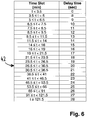
- Figure 6 shows a mapping table for translating the length of the cooling interval into a corresponding delay time for the power interruption interval.
- the first column indicates the length of the cooling interval 39
- the second column indicates the corresponding delay time in seconds for the timing of the power interruption interval 41.
- the length of the power interruption interval 41 is constantly kept at 10 seconds, no matter how long the preceding cooling interval 39 has been. From the entry 42 in the table of figure 6 , it can be seen that for a length of the cooling interval 39 in the range between 26.5 minutes and 30.5 minutes, the delay time between the start of the heating phase 37 and the power interruption interval 41 is twenty seconds. This corresponds to the time pattern shown in figure 5 .
- the delay time is varied in dependence on the preceding cooling interval 39 while the length of the power interruption interval 41 is kept constant.
- the length of the power interruption interval may be varied in dependence on the preceding course of the heating process as well.
- both the delay time and the length of the power interruption interval or only the length of the power interruption interval may be varied in dependence on the preceding course of the heating process, for example in dependence on the length of the cooling interval 39.
Landscapes
- Engineering & Computer Science (AREA)
- Textile Engineering (AREA)
- Irons (AREA)
Abstract
Description
- The invention relates to an iron comprising a soleplate, a heating element thermally coupled with the soleplate and a thermostat unit configured for controlling operation of the heating element. The invention further relates to a method for operating a heating element of an iron.
- In the international patent application
WO 1995/032551 A1 , an automatic power interrupting apparatus for an electric appliance is described that may for example be used for a hand held electrically operated appliance, such as a pressing iron. The automatic switching apparatus is provided within a circuit board located within the housing of the iron. The automatic switching apparatus includes a first timing circuit and a touch sensitive switch which function in conjunction with one another such that when the user breaks contact with the touch sensitive switch, located on a handle portion of the iron, the first timing circuit is enabled to de-energize the heating element of the iron after contact has been broken with the touch sensitive switch for a predetermined period of time. A second timing circuit is provided to disable the first timing circuit for a second predetermined period of time when the iron is initially plugged into the electrical socket outlet so as to permit the heating element to reach a temperature level suitable for ironing without necessitating the user to contact the touch sensitive switch when the heating element is initially energized. A temperature sensitive circuit may also be provided to de-energise the heating element at a predetermined temperature. - It is an object of the invention to provide an iron with an improved temperature control during the heating phase. In particular, it is an object of the invention to improve the heating process for irons equipped with a simple thermostat.
- According to the invention, an iron is provided, the iron comprising a soleplate, a heating element thermally coupled with the soleplate, a thermostat unit configured for controlling operation of the heating element, the thermostat unit being configured for alternatingly effecting heating phases and non-heating phases of the heating element, a switch element adapted for switching a power supply of the heating element, and a control unit adapted for controlling a switching operation of the switch element. The control unit is configured for assigning a respective time pattern defining one or more power interruption intervals to at least one selected heating phase of said heating phases, with the switch element being configured for interrupting power supply of the heating element during the one or more power interruption intervals in accordance with the respective time pattern.
- During a selected heating phase, one or more power interruption intervals occur, with power supply of the heating element being interrupted during these power interruption intervals. The advantage is that during the one or more time intervals, a temperature equilibration of the temperature at the soleplate can take place. Thus, the detrimental effects caused by the thermal inertia of the soleplate can be reduced or even eliminated. In particular, by including one or more power interruption intervals into the heating phase, temperature overshoots can be avoided. Especially when ironing delicate garments, temperature overshoots may lead to damages. By choosing a time pattern of the one power interruptions that is adapted to the thermal inertia of the respective iron, temperature overshoots can be avoided and the temperature control of the heating process can be performed more accurately than before. Even in irons equipped with a simple thermostat like for example a mechanical thermostat or a simple electronic thermostat, the heating process is stabilised and a more accurate control of the soleplate's temperature is accomplished.
- The time pattern may for example define the timing of the one or more power interruption intervals during a selected heating phase. The time pattern can be adapted to the respective characteristics. The time pattern of the power interruptions may be chosen such that the thermal inertia of the iron's soleplate is taken into account. The time pattern of the power interruptions may be chosen such that the effects due to thermal inertia of the soleplate are reduced or avoided.
- Further according to the invention, a method for operating a heating element of an iron is provided. The iron comprises a soleplate, the heating element being thermally coupled with the soleplate, a thermostat unit configured for controlling operation of the heating element, and a switch element configured for switching a power supply of the heating element. The method comprising the steps of heating the soleplate according to alternating heating phases and non-heating phases under the control of the thermostat unit, determining a respective time pattern defining one or more power interruption intervals for at least one selected heating phase of said heating phases, and interrupting power supply of the heating element during the one or more power interruption intervals in accordance with the respective time pattern.
- By providing one or more power interruptions during a heating phase, the heating process is stabilised and effects that are due to thermal inertia of the soleplate can be reduced or even eliminated. In particular, temperature overshoots that may damage the garment are avoided. Even for irons equipped with a simple thermostatic control, the temperature control during the heating process is improved.
- Preferred features of the invention which may be applied alone or in combination are discussed below and in the dependent claims.
- Preferably, the respective time pattern defining the one or more power interruption intervals is specified by one or more timing parameters. For example, the timing parameters may indicate the respective positions of the one or more power interruption intervals during the heating phase.
- Preferably, the timing parameters for the one or more power interruption intervals of a selected heating phase comprise at least one of a delay time that specifies a time delay between an onset of the selected heating phase and a start of the power interruption interval in said heating phase and a length of the power interruption interval. Thus, the timing parameters can specify the respective position and duration of the one or more power interruption intervals.
- Preferably, the one or more power interruption intervals are enforced by the control unit in accordance with timing parameters chosen in dependence on a preceding course of the heating process. Thus, the previous heating behaviour can be considered when choosing the time pattern defining the one or more power interruption intervals during a heating phase. By choosing the timing parameters in dependence on a preceding course of the heating process, a heating process with reduced temperature overshoots is accomplished.
- Preferably, the thermostat unit is configured for controlling operation of the heating element in a way that the temperature of the soleplate is brought to and kept at a temperature in the vicinity of a predefined target temperature. The sequence of heating phases and non-heating phases is chosen such that a desired target temperature is reached.
- Preferably, the one or more power interruption intervals of a selected heating phase are part of the selected heating phase. The selected heating phase comprises the one or more power interruption intervals, which occur during the selected heating phase. Preferably, the length of a power interruption interval of a selected heating phase is smaller than the duration of the selected heating phase in which the power interruption is effected. Preferably, the length of a power interruption interval of a selected heating phase is less than one third of the selected heating phase in which the power interruption is effected. Further preferably, the length of a power interruption interval of a selected heating phase is less than one fourth of the selected heating phase in which the power interruption is effected. Further preferably, the length of a power interruption interval of a selected heating phase is less than one fifth of the selected heating phase in which the power interruption is effected. Further preferably, the length of a power interruption interval of a selected heating phase is less than one tenth of the selected heating phase in which the power interruption is effected.
- Preferably, the control unit is a timer unit. Preferably, the timer unit is programmed to initiate the one or more power interruption intervals during the selected heating phases. The timer unit can for example be programmed to control the time pattern of the one or more power interruption intervals.
- Preferably, the iron comprises an auto switch-off unit configured for switching off the power supply of the heating element in case the iron is not moved during a predetermined period of time. In another construction, the auto switch-off unit can for example be configured for switching off the power of the heating element in case the iron is not gripped during a predetermined period of time. For example, a touch sensitive sensor may be used for detecting that the user touches or grips the iron. The purpose of an auto switch-off unit is to avoid safety hazards and damages to the clothing. When the iron is not moved or gripped during a predetermined period of time, the iron is powered down.
- Preferably, the iron comprises an auto switch-off unit, with the control unit and the switch element being part of the auto switch-off unit. In addition to controlling the auto switch-off function, the control unit and the switch element of the auto switch-off unit can also be used for controlling the time pattern of the one or more power interruptions during a heating phase and for switching the heating element in accordance with this time pattern. Hence, the control unit and the switch element can be used for two different purposes. For implementing the invention, an additional routine has to be implemented in the control unit. No extra hardware is required for implementing the method of the present invention, and hence, a cost saving is accomplished.
- Preferably, the auto switch-off unit comprises the control unit and the switch element, with the auto switch-off unit being configured for detecting if the iron is not moved or gripped for a predetermined period of time, wherein in this case, the control unit is configured for controlling the switch element in a way that the heater element is powered off.
- Preferably, the auto switch-off unit further comprises a sensor configured for detecting movements of the iron. The sensor signals are evaluated by the control unit of the auto switch-off unit. Thus, the control unit can detect that the iron is not moved during a predefined period of time. Further preferably, the auto switch-off unit may comprise a sensor configured for detecting whether or not the user touches or grips the iron.
- Preferably, the sensor is configured for additionally determining an orientation of the iron. For example, the sensor may detect if the iron is in its horizontal position or in an upright position. Preferably, the auto switch-off unit comprises a ball sensor configured for detecting movements and orientation of the iron. A ball sensor is capable of detecting both movements and orientation of the iron.
- Preferably, in case the sensor determines that the iron is not moved or gripped and the soleplate is in a horizontal orientation, the heating element is powered off after a first period of inactivity and remains in the power-down state until a further movement of the iron is detected. In case the iron is in a horizontal orientation, it is particularly important to quickly shut down the power supply, in order to prevent damage to the clothing.
- Preferably, in case the sensor determines that the iron is not moved or gripped and the soleplate is in an upright orientation, the heating element is powered off after a second period of inactivity and remains in the power-down state until it is detected that the iron is moved or that the user grips the iron, with the second interval being larger than the first interval. In this case, it is not necessary to immediately shut down the iron, and for this reason, the second interval may for example be in the range of minutes.
- Preferably, the switch element is a relay. A relay is characterised by a robust and reliable switching behaviour. Further preferably, the switch element is a power semiconductor.
- Preferably, the heating phases comprise an initial heating phase after power on of the iron and subsequent heating phases. Preferably, the iron comprises an auto switch-off unit, wherein the heating phases of the heating element comprise at least one of an initial heating phase that takes place when the iron is powered on and a subsequent heating phase that takes place when the heating element is powered up after being powered off during a period of inactivity. For example, during the period of inactivity, the iron may cool down. When the iron is heated up again, temperature overshoots are likely to occur. Accordingly, one or more power interruption intervals should be included into the heating phase.
- Preferably, the switch element is connected in series with the thermostat unit. Thus, the switch element can power down the heating element during the one or more power interruption intervals.
- Preferably, the one or more power interruption intervals are configured for reducing or suppressing temperature overshoots that are due to the soleplate's thermal inertia during the at least one selected heating phase. By reducing thermal overshoots, damages to the garments can be avoided.
- Preferably, during the one or more power interruption intervals enforced by the switch element, an equilibration of the soleplate's temperature is effected. The temperature equilibration stabilises the course of the temperature during the heating process.
- Preferably, the one or more power interruption intervals are configured to allow for a temperature equilibration in order to compensate for a thermal inertia of the soleplate.
- Preferably, the thermostat unit is a mechanical thermostat. Especially in case the temperature control is performed by a mechanical thermostat, temperature overshoots are likely to occur. By providing for a temperature equilibration, these overshoots can be reduced. Preferably, the thermostat unit comprises a bimetal element configured for controlling the heating phases and the non-heating phases of the heating element.
- Preferably, the iron is a dry iron or a steam iron or a motor steam iron or an iron connected to a steam station. Preferably, the iron is a one-temperature device configured for operating at one single target temperature. In a simple and cheap appliance, the one or more power interruptions allow for a more accurate heating process.
- Preferably, the iron comprises a temperature dial for selecting a desired target temperature. Also in irons with a range of possible target temperatures, an improvement of the heating process is accomplished.
- Preferably, the iron comprises a heating lamp and wherein the control unit is configured for enforcing a single interruption interval at the end of a selected heating phase. When the lamp goes off, the user will assume that the heating process is finished and that the device is ready to be used. In order to avoid confusion of the user, it is advantageous to provide a single interruption interval at the end of the heating phase. Preferably, the iron comprises a heating lamp and wherein the time pattern of the power interruption intervals are chosen such that there is a single power interruption interval at the end of a selected heating phase.
- Preferably, the iron comprises an auto switch-off unit, wherein in case a subsequent heating phase is performed after a preceding deactivation phase initiated by the auto switch-off unit, the control unit is configured for mapping a duration of the preceding deactivation phase into a time pattern for the one or more power interruption intervals during a subsequent heating phase. Further preferably, the iron comprises an auto switch-off unit, the control unit being configured for mapping a duration of a deactivation phase of the heating element into a time pattern for the one or more power interruption intervals of a subsequent heating phase. Preferably, the longer the deactivation phase is, the later the at least one power interruption interval during a subsequent heating phase will occur.
- The invention is illustrated in greater detail with the aid of schematic drawings. It shows schematically:
-
Figure 1: Fig. 1 shows a steam iron comprising a mechanical thermostat and an auto switch-off unit. -
Figure 2: Fig. 2 shows two heating curves related to a mechanical thermostat and to an electronic thermostat. -
Figure 3: Fig. 3 shows a modified heating curve, with the heating phase comprising a power interruption interval. -
Figure 4: Fig. 4 shows a dedicated control unit configured for enforcing one or more power interruptions during the heating phase. -
Figure 5: Fig. 5 shows a cooling phase related to a period of inactivity followed by a subsequent heating phase. -
Figure 6: Fig. 6 shows a mapping table for translating the duration of the cooling interval into a delay time for a power interruption interval. - In the following description of preferred embodiments of the present invention, identical reference numerals denote identical or comparable components.
-
Figure 1 shows a cross section of a steam iron 1, the steam iron 1 comprising asoleplate 2, a housing 3, ahandle 4 and a power supply 5. For heating up thesoleplate 2 to a desired temperature, the steam iron 1 comprises aheating element 6 that is thermally coupled with thesoleplate 2. The steam iron 1 further comprises a steam chamber 7 arranged above thesoleplate 2 and awater tank 8 located above the steam chamber 7. Thewater tank 8 may contain a volume ofwater 9 and is adapted for supplying a flow of water to the steam chamber 7 via awater dosage device 10. In the steam chamber 7, the water is evaporated, and steam is ejected at a plurality ofsteam outlet ports 11 located in thesoleplate 2. - The steam iron 1 is equipped with a
thermostat unit 12 that provides a thermostatic control of the operation ofheating element 6. In dependence on thesoleplate 2's temperature, thethermostat unit 12 is configured for controlling the heating operation of theheating element 6. For example, thethermostat unit 12 may be a mechanical thermostat unit, but it may as well be a simple electronic thermostat unit. In this respect, heating phases alternate with non-heating phases, in order to maintain thesoleplate 2's temperature in the vicinity of a desired target temperature. Thethermostat unit 12 may for example comprise a bimetal element, with the bimetal element's deformation depending on the temperature of thesoleplate 2. If the temperature of thesoleplate 2 drops below a predefined threshold, the bimetal element activates theheating element 6. As soon as a certain upper temperature is reached, theheating element 6 is switched off by the bimetal element. - The steam iron 1 shown in
figure 1 further comprises an auto switch-offunit 13 configured for powering down theheating element 6 in case the steam iron 1 is not moved or gripped during a predefined period of time. The auto switch-off function improves the safety of the steam iron 1's operation, because the steam iron 1 is automatically powered-off when it is not used anymore, thus avoiding safety hazards. The auto switch-off function may also be referred to as a SensorSecure function of the iron. For realising the auto switch-off function, the auto switch-offunit 13 comprises aswitch element 14 connected in series with thethermostat unit 12. The switching operation of theswitch element 14 is controlled by acontrol unit 15. Preferably, thecontrol unit 15 is implemented as a programmable timer unit. Asensor 16 is connected to thecontrol unit 15, with the sensor signals generated by thesensor 16 being evaluated by thecontrol unit 15. In case thecontrol unit 15 detects that the iron 1 has not been moved or gripped for a period of time that exceeds a predefined threshold, thecontrol unit 15 will control theswitch element 14 in a way that the power supply of theheating element 6 is interrupted. - The
sensor 16 may be realised as a motion sensor adapted for detecting movements of the iron 1. Alternatively, thesensor 16 may be realised as a touch sensitive sensor configured for detecting whether or not the user touches or grips the iron. Thesensor 16 may also be configured for additionally detecting an orientation of the iron 1. For example, thesensor 16 may detect if the iron 1 and the iron 1'ssoleplate 2 are in a horizontal position or in an upright position. In case thesoleplate 2 is in a horizontal position, the iron 1 should be switched off quickly, and for this reason, the threshold time is set to a comparatively short threshold time of for example 30 seconds. In case the iron 1 and thesoleplate 2 are in an upright position, the situation is less critical. In this case, the time threshold for powering down the iron 1 is set to a comparatively large value, for example to 8 minutes. Asensor 16 for detecting both motion and orientation of the iron 1 may for example be realised as a ball sensor comprising a ball that is movably accommodated in a cage. By detecting a displacement of the ball relative to the cage, motion and orientation of the iron 1 can be detected. - In
figure 1 , a steam iron 1 is shown. However, embodiments of the present invention are not limited to a steam iron, but may also be applied to a dry iron, to a motor steam iron or to an iron connected to a steam station. The iron may either be a one-temperature device configured for bringing the soleplate to a predetermined target temperature, but embodiments of the present invention may also relate to an iron comprising a temperature dial for selecting a desired target temperature, whereby the selection may for example depend on the type of garment to be ironed. -
Figure 2 shows the temperature (in °C) of the soleplate as a function of time (in minutes) during a heating phase of the iron. Theheating curve 17 relates to an iron comprising an electronic thermostat, whereas theheating curve 18 has been acquired for an iron equipped with a mechanical thermostat, for example a thermostat of the bimetal type. Both theheating curve 17 and theheating curve 18 start at a temperature of about 20°C and show the initial heating phase that takes place when the iron is plugged in. In thetemperature curve 18 controlled by a mechanical thermostat there is atemperature overshoot 19 after the initial heating phase, with the temperature of this overshoot (about 240°C) being considerably higher than the stabilised temperature of about 190°C. Thistemperature overshoot 19 is due to the thermal inertia of thesoleplate 2, with said thermal inertia depending on the mass distribution of thesoleplate 2. When thesoleplate 2 is heated up, it takes a while until a temperature equilibration is accomplished, and for this reason, theheating element 6 continues heating during theovershoot 19 until it is switched off by thethermostat unit 12. Especially when ironing delicate garments, for example clothing with a one dot care symbol, these temperature overshoots may cause problems, because the temperature peak may lead to irreversible marks, garment hardening, shrinking or burns. Therefore, it would be desirable to reduce or even eliminate thetemperature overshoot 19. After thetemperature overshoot 19 has occurred, the temperature is stabilised, but the temperature variations of thecurve 18 are still higher than in thecorresponding heating curve 17 related to an electronic thermostat. In theheating curve 18, the graph is not flat, but has a cutting saw shape. - In contrast, the
heating curve 17 has been acquired for an iron where the temperature control is done by an electronic thermostat. The electronic thermostat comprises a temperature sensor that gives information to an electronic control unit. From theheating curve 17, it can be seen that there is no temperature overshoot. As soon as the temperature is stabilised, the temperature variation is very low and the graph is quite flat. Using an electronic control, there is a nearly constant flow of temperature information between the temperature sensor and the electronics and it is therefore possible to control these overshoots by implementing a dedicated logic in the electronics. With a mechanical thermostat, on the contrary, there is no option to inform the electronics about the progression of temperature. Hence, there is a need to reduce or avoid thermal overshoots. - For reducing the overshoots, it is suggested to interrupt the power supply of the
heating element 6 at one or more power interruption intervals during the heating phase of theheater element 6. Compared to the total duration of the heating phase, the length of the one or more power interruption intervals is comparatively short, for example in the range of several seconds. Nevertheless, during the one or more power interruption intervals, a temperature equilibration may take place, and as a consequence, effects like overshoot are reduced. Infigure 3 , a modifiedheating curve 20 is shown as a function of time, the modifiedheating curve 20 comprising at least onepower interruption interval 21. For comparison, theoriginal heating curve 22 with theovershoot 23 is indicated with dotted lines. By comparing the modifiedheating curve 20 and theoriginal heating curve 22, it can be seen that theovershoot 24 of the modifiedheating curve 20 is considerably reduced relative theoriginal overshoot 23, with the maximum temperature being about 210°C. As a consequence, no detrimental effects occur when ironing delicate garments. In particular, irreversible marks, garment hardening, shrinking or burns are prevented. - In the example of
figure 3 , the power interruption takes place during thepower interruption interval 21 with a delay of 26 seconds relative to the start of the heating phase. The length of thepower interruption interval 21 is set to 10 seconds. Hence, the duration of the power interruption interval is considerably shorter than the duration of the heating phase. In particular, the power interruption takes place during a comparatively small sub-interval of the heating phase, with the length of the power interruption interval being for example less than one third of the duration of the heating phase, or less than one fourth of the duration of the heating phase, or less than one fifth of the duration of the heating phase. - Preferably, for switching off the
heating element 6 during thepower interruption interval 21, the components of the auto switch-offunit 13 shown infigure 1 are utilised. In particular, thecontrol unit 15 and theswitch element 14 can be utilised for realising an auto switch-off functionality and for enforcing a power down of theheating element 6 during the one or morepower interruption intervals 21. As can be seen infigure 1 , theswitch element 14 is connected in series with thethermostat unit 12 and is capable of disrupting the power supply to theheating element 6. Theswitch element 14 may for example be realized as a relay. Thecontrol unit 15 can be implemented as a programmable timer unit that is responsible both for performing the auto switch-off function and for controlling theswitch element 14 in a way that power of theheating element 6 is switched off during the one or morepower interruption intervals 21. For example, timing parameters defining the time pattern of the one or morepower interruption intervals 21 may be stored in thecontrol unit 15. For each of the power interruption intervals, a respective time delay relative to the on-set of the heating phase and a respective duration of the power interruption interval may be stored. - In the lower part of
figure 3 , the switching operation of theswitch element 14 is shown as a function of time. Initially, at the start of the heating phase, theswitch element 14 is switched on during adelay time 25 of for example t = 26 seconds. During thisdelay time 25, thesoleplate 2 is heated up by theheating element 6. After thedelay time 25, theswitch element 14 switches off the power supply for theheating element 6, and during thepower interruption interval 21, theheating element 6 is powered off. During thepower interruption interval 21, a thermal equilibration of thesoleplate 2's temperature can take place. At the end of thepower interruption interval 21, theswitch element 14 is switched on again, and during thesubsequent interval 26, power is supplied to theheating element 6. In the further course of the heating process shown infigure 3 , theswitch element 14 remains switched on, with the alternating sequence of heating phases and non-heating phases being solely controlled by thethermostat unit 12. - Using the components of the auto switch-off
unit 13 for realising thepower interruption intervals 21 allows for improving the heating behavior of the iron 1 at almost no extra cost, because both theswitch element 14 and thecontrol unit 15 are already present in the iron 1. Hence, it is sufficient to provide an additional routine in thecontrol unit 15. - However, it is also possible to use a dedicated control circuit for implementing a power-down functionality at one or more power interruption intervals during the heating phase. In this case, the iron 1 's auto switch-off function or a SensorSecure function is not required.
Figure 4 shows a set-up comprising a dedicated control circuit configured for enforcing the one or more power interruption intervals. The set-up infigure 4 comprises apower supply 27, aheating element 28, athermostat unit 29 and adedicated control circuit 30 configured for shutting off the power supply to theheating element 28 during the one or more power interruption intervals. - The
dedicated control circuit 30 comprises aswitch element 31 and acontrol unit 32 configured for controlling the switching of theswitch element 31. Thecontrol unit 32 may for example be implemented as a programmable timer unit. At thecontrol unit 32, timing parameters defining the time pattern of the one or more power interruption intervals may be stored. For example, for each of the one or more power interruption intervals, a respective delay time and a respective duration of the interruption interval may be stored. - The iron 1 may for example comprise a heating lamp connected in parallel to the
heating element 6 or to theheating element 28. In this case, it may be advantageous to provide for a uniquepower interruption interval 21 that is disposed as close as possible to the heating lamp's shut-down, i.e. as close as possible to the end of the heating phase. According to the user manual, the iron is ready to use as soon as the heating light switches off. In order to avoid a confusion of the user, the power interruption interval should be arranged at the end of the heating phase. As shown infigure 3 , the result is that the heating lamp is powered off earlier. Instead of being powered off at the point of time 33, the heating lamp is already powered off at the modified point of time 34. Accordingly, a switch-off of the heating lamp still indicates to the user that the appliance is ready to be used. To avoid a blinking of the heating lamp, the heating phase should only comprise one power interruption interval that is disposed close to the end of the heating phase. - However, the time pattern for the one or more power interruption intervals could be individually chosen for a respective device. The different mass and temperature distribution of a soleplate, the presence or absence of the heating lamp, the presence or absence of an anti-drip disk, etc. would define how to interrupt the power via electronics to avoid the temperature overshoots.
- In
figure 3 , it has been shown how temperature overshoots of the soleplate's initial heating phase can be reduced. But the problem of temperature overshoots may also occur in case the device is powered down by the auto switch-off function or SensorSecure function because it is not moved or gripped for a certain period of time. Then, the user may move the iron or grip the iron and initiate a subsequent heating phase of the heating element. During the period of inactivity, the soleplate may have cooled down considerably. Hence, when the soleplate is heated up again, temperature overshoots may occur during the subsequent heating phase. Also in this case, the proposed solution is that power interruption intervals are included in the subsequent heating phase in order to reduce or even eliminate the temperature overshoots. -
Figure 5 shows atemperature curve 35 indicating thesoleplate 2's temperature (in °C) as a function of time, with thetemperature curve 35 comprising acooling phase 36 and asubsequent heating phase 37. At the point oftime 38, the heating element is powered down by the auto switch-off function after a period of inactivity. As indicated in the lower part offigure 5 , theswitch element 14 of the auto switch-offunit 13 is powered off at the point oftime 38 and remains in the switched-off state during thecooling interval 39. At the point oftime 40, the user moves the iron or grips the iron 1. Thecontrol unit 15 detects this event by evaluating the signals of thesensor 16 and switches on theswitch element 14, as indicated in the lower part offigure 5 . As a consequence, thesubsequent heating phase 37 is initiated. As thecooling phase 36 may have been quite long, for example in the range of 30 minutes, thesoleplate 2 may have cooled down considerably when thesubsequent heating phase 37 starts. Accordingly, during thesubsequent heating phase 37, temperature overshoots may occur as well. - The proposed solution is that depending on the
cooling phase 36 of thesoleplate 2, one ormore power interruptions 41 could also be included into thesubsequent heating phase 37 in order to minimise the temperature overshoots. In the lower part offigure 5 , apower interruption interval 41 that occurs during thesubsequent heating phase 37 is depicted, with theheating element 6 being powered down during thepower interruption interval 41. The power interruption may be performed with a time delay of 20 seconds after the start of thesubsequent heating phase 37 and thepower interruption interval 41 may have a length of for example 10 seconds. In this regard, it is advantageous if the timing parameters of the one or more power interruption intervals that occur during the subsequent heating phase are chosen in dependence on the precedingcooling phase 36. The longer thecooling phase 36 has been, the lower the temperature at the onset of thesubsequent heating phase 37 will be, and the longer the heating of thesoleplate 2 will take. Accordingly, in the preferred embodiment, the delay time of thepower interruption interval 41 is chosen in dependence on the duration of the precedingcooling interval 39. The longer the coolinginterval 39, the longer the delay time will be, whereas the duration of thepower interruption interval 41 is always kept at ten seconds. -
Figure 6 shows a mapping table for translating the length of the cooling interval into a corresponding delay time for the power interruption interval. The first column indicates the length of the coolinginterval 39, whereas the second column indicates the corresponding delay time in seconds for the timing of thepower interruption interval 41. The length of thepower interruption interval 41 is constantly kept at 10 seconds, no matter how long the precedingcooling interval 39 has been. From theentry 42 in the table offigure 6 , it can be seen that for a length of the coolinginterval 39 in the range between 26.5 minutes and 30.5 minutes, the delay time between the start of theheating phase 37 and thepower interruption interval 41 is twenty seconds. This corresponds to the time pattern shown infigure 5 . - In the example shown in
figures 5 and6 , the delay time is varied in dependence on the precedingcooling interval 39 while the length of thepower interruption interval 41 is kept constant. However, the length of the power interruption interval may be varied in dependence on the preceding course of the heating process as well. For example, both the delay time and the length of the power interruption interval or only the length of the power interruption interval may be varied in dependence on the preceding course of the heating process, for example in dependence on the length of the coolinginterval 39. - The features described in the above description, claims and figures can be relevant to the invention in any combination. Their reference numerals in the claims have merely been introduced to facilitate reading of the claims. They are by no means meant to be limiting.
-
- 1
- steam iron
- 2
- soleplate
- 3
- housing
- 4
- handle
- 5
- power supply
- 6
- heating element
- 7
- steam chamber
- 8
- water tank
- 9
- water
- 10
- water dosage device
- 11
- steam outlet ports
- 12
- thermostat unit
- 13
- auto switch-off unit
- 14
- switch element
- 15
- control unit
- 16
- sensor
- 17
- heating curve for electronic thermostat
- 18
- heating curve for mechanical thermostat
- 19
- temperature overshoot
- 20
- modified heating curve with power interruption interval
- 21
- power interruption interval
- 22
- heating curve without power interruption interval
- 23
- temperature overshoot
- 24
- reduced temperature peak
- 25
- delay time
- 26
- switched-on state of the switch element
- 27
- power supply
- 28
- heating element
- 29
- thermostat unit
- 30
- dedicated control circuit
- 31
- switch element
- 32
- control unit
- 33
- point of time when heating lamp is shut off
- 34
- modified point of time when heating lamp is shut off
- 35
- temperature curve
- 36
- cooling phase
- 37
- heating phase
- 38
- point of time when iron is deactivated
- 39
- cooling interval
- 40
- point of time when iron is reactivated
- 41
- power interruption interval
- 42
- entry of mapping table
Claims (15)
- An iron (1) comprising
a soleplate (2),
a heating element (6, 28) thermally coupled with the soleplate (2),
a thermostat unit (12, 29) configured for controlling operation of the heating element (6, 28), the thermostat unit (12, 29) being configured for alternatingly effecting heating phases and non-heating phases of the heating element (6, 28),
a switch element (14, 31) adapted for switching a power supply of the heating element (6, 28),
a control unit (15, 32) adapted for controlling a switching operation of the switch element (14, 31),
characterised in that
the control unit (15, 32) is configured for assigning a respective time pattern defining one or more power interruption intervals (21, 41) to at least one selected heating phase of said heating phases, with the switch element (14, 31) being configured for interrupting power supply of the heating element (6, 28) during the one or more power interruption intervals (21, 41) in accordance with the respective time pattern. - The iron (1) according to claim 1, wherein the respective time pattern defining the one or more power interruption intervals (21, 41) is specified by one or more timing parameters.
- The iron (1) according to claim 2, wherein the timing parameters for the one or more power interruption intervals (21, 41) of a selected heating phase comprise at least one of:a delay time (25) that specifies a time delay between an onset of the selected heating phase and a start of the power interruption interval (21, 41) in said heating phase,a length of the power interruption interval (21, 41).
- The iron (1) according to claim 2 or claim 3, wherein the one or more power interruption intervals (21, 41) are enforced by the control unit (15, 32) in accordance with timing parameters chosen in dependence on a preceding course of the heating process.
- The iron (1) according to any one of claims 1 to 4, wherein the one or more power interruption intervals (21, 41) of a selected heating phase are part of the selected heating phase.
- The iron (1) according to any one of claims 1 to 5, wherein the iron (1) comprises an auto switch-off unit (13) configured for switching off the power supply of the heating element (6, 28) in case the iron (1) is not moved or gripped during a predetermined period of time.
- The iron (1) according to any one of claims 1 to 6, wherein the iron (1) comprises an auto switch-off unit (13), with the control unit (15, 32) and the switch element (14, 31) being part of the auto switch-off unit (13).
- The iron (1) according to any one of claims 1 to 7, wherein the iron (1) comprises an auto switch-off unit (13), wherein the heating phases of the heating element (6, 28) comprise at least one of:an initial heating phase that takes place when the iron (1) is powered on,a subsequent heating phase (37) that takes place when the heating element (6, 28) is powered up after being powered off during a period of inactivity.
- The iron (1) according to any one of claims 1 to 8, wherein the switch element (14, 31) is connected in series with the thermostat unit (12, 29).
- The iron (1) according to any one of claims 1 to 9, wherein the one or more power interruption intervals (21, 41) are configured for reducing or suppressing temperature overshoots (23) that are due to the soleplate 2's thermal inertia during the at least one selected heating phase.
- The iron (1) according to any one of claims 1 to 10, wherein the one or more power interruption intervals (21, 41) are configured to allow for a temperature equilibration in order to compensate for a thermal inertia of the soleplate (2).
- The iron (1) according to any one of claims 1 to 11, wherein the thermostat unit (12, 29) is a mechanical thermostat.
- The iron (1) according to any one of claims 1 to 12, wherein the thermostat unit (12, 29) comprises a bimetal element configured for controlling the heating phases and the non-heating phases of the heating element (6, 28).
- The iron (1) according to any one of claims 1 to 13, wherein the iron (1) is a one-temperature device configured for operating at one single target temperature.
- A method for operating a heating element (6, 28) of an iron (1),
the iron (1) comprising a soleplate (2), the heating element (6, 28) being thermally coupled with the soleplate (2),
a thermostat unit (12, 29) configured for controlling operation of the heating element (6, 28), and
a switch element (14, 31) configured for switching a power supply of the heating element (6, 28),
the method comprising the steps of
heating the soleplate (2) according to alternating heating phases and non-heating phases under the control of the thermostat unit (12, 29),
determining a respective time pattern defining one or more power interruption intervals (21, 41) for at least one selected heating phase of said heating phases, interrupting power supply of the heating element (6, 28) during the one or more power interruption intervals (21, 41) in accordance with the respective time pattern.
Priority Applications (1)
| Application Number | Priority Date | Filing Date | Title |
|---|---|---|---|
| PL18172428T PL3409828T3 (en) | 2017-05-31 | 2018-05-15 | Heating control with reduced temperature overshoots for an iron and corresponding method |
Applications Claiming Priority (2)
| Application Number | Priority Date | Filing Date | Title |
|---|---|---|---|
| ES201730751A ES2692366A1 (en) | 2017-05-31 | 2017-05-31 | CONTROL OF HEATING WITH REDUCTION OF THE PEAKS OF EXCESS TEMPERATURE FOR A PLATE (Machine-translation by Google Translate, not legally binding) |
| DE102017217324.6A DE102017217324B4 (en) | 2017-05-31 | 2017-09-28 | Heating control with reduced temperature overshoots for an iron |
Publications (3)
| Publication Number | Publication Date |
|---|---|
| EP3409828A1 true EP3409828A1 (en) | 2018-12-05 |
| EP3409828B1 EP3409828B1 (en) | 2021-06-30 |
| EP3409828B2 EP3409828B2 (en) | 2024-10-30 |
Family
ID=62186266
Family Applications (1)
| Application Number | Title | Priority Date | Filing Date |
|---|---|---|---|
| EP18172428.7A Active EP3409828B2 (en) | 2017-05-31 | 2018-05-15 | Heating control with reduced temperature overshoots for an iron and corresponding method |
Country Status (2)
| Country | Link |
|---|---|
| EP (1) | EP3409828B2 (en) |
| PL (1) | PL3409828T3 (en) |
Citations (5)
| Publication number | Priority date | Publication date | Assignee | Title |
|---|---|---|---|---|
| US2409420A (en) * | 1942-03-26 | 1946-10-15 | Westinghouse Electric Corp | Heating appliance |
| JPH05305200A (en) * | 1992-04-30 | 1993-11-19 | Matsushita Electric Ind Co Ltd | Electric iron |
| WO1995032551A1 (en) | 1994-05-19 | 1995-11-30 | Pentalpha Enterprises Limited | Automatic power interrupting apparatus for an electric appliance |
| DE102010041342A1 (en) * | 2010-07-21 | 2012-01-26 | BSH Bosch und Siemens Hausgeräte GmbH | Electrically heated apparatus, in particular iron, and method for controlling such apparatus |
| WO2016156179A1 (en) * | 2015-03-30 | 2016-10-06 | Koninklijke Philips N.V. | An ironing appliance with means for controlling the heating power |
Family Cites Families (5)
| Publication number | Priority date | Publication date | Assignee | Title |
|---|---|---|---|---|
| US4661685A (en) | 1985-09-06 | 1987-04-28 | John Zink Company | Electronic pressing iron |
| US4812625A (en) | 1987-09-30 | 1989-03-14 | Food Automation-Service Techniques, Inc. | Temperature control system for cooking apparatus |
| EP0768015B1 (en) | 1995-04-25 | 2004-06-30 | Koninklijke Philips Electronics N.V. | Safety device for an electric heating appliance |
| DE202010000152U1 (en) | 2010-02-09 | 2010-06-02 | Finkenzeller, Andreas | Automatic iron shut-off device |
| BR112013015661B1 (en) | 2010-12-23 | 2020-11-17 | Koninklijke Philips N.V. | DEVICE OF PASSING CLOTHES STEAM |
-
2018
- 2018-05-15 PL PL18172428T patent/PL3409828T3/en unknown
- 2018-05-15 EP EP18172428.7A patent/EP3409828B2/en active Active
Patent Citations (5)
| Publication number | Priority date | Publication date | Assignee | Title |
|---|---|---|---|---|
| US2409420A (en) * | 1942-03-26 | 1946-10-15 | Westinghouse Electric Corp | Heating appliance |
| JPH05305200A (en) * | 1992-04-30 | 1993-11-19 | Matsushita Electric Ind Co Ltd | Electric iron |
| WO1995032551A1 (en) | 1994-05-19 | 1995-11-30 | Pentalpha Enterprises Limited | Automatic power interrupting apparatus for an electric appliance |
| DE102010041342A1 (en) * | 2010-07-21 | 2012-01-26 | BSH Bosch und Siemens Hausgeräte GmbH | Electrically heated apparatus, in particular iron, and method for controlling such apparatus |
| WO2016156179A1 (en) * | 2015-03-30 | 2016-10-06 | Koninklijke Philips N.V. | An ironing appliance with means for controlling the heating power |
Also Published As
| Publication number | Publication date |
|---|---|
| EP3409828B2 (en) | 2024-10-30 |
| EP3409828B1 (en) | 2021-06-30 |
| PL3409828T3 (en) | 2021-11-29 |
Similar Documents
| Publication | Publication Date | Title |
|---|---|---|
| JP4553541B2 (en) | Steam iron | |
| EP2750560B1 (en) | A heater | |
| KR100246177B1 (en) | Auto power cutoff device of electric device | |
| US10443186B2 (en) | Steam iron | |
| KR101971569B1 (en) | Overflow prevention control method and food processor of food processor | |
| JPH09510905A (en) | Quick cooling steam iron | |
| EP3409828B2 (en) | Heating control with reduced temperature overshoots for an iron and corresponding method | |
| CN107429474B (en) | Ironing appliance with means for controlling the heating power | |
| JP5591029B2 (en) | Induction heating cooker | |
| ES2881528T3 (en) | Heat control with reduced temperature overdrafts for one iron and associated procedure | |
| JP3788276B2 (en) | Induction heating cooker | |
| KR200327803Y1 (en) | Safety Smoothing Iron | |
| KR20120002151U (en) | Electric iron for fire prevention | |
| JP3044946B2 (en) | Iron | |
| KR100351941B1 (en) | A controlling method of cavity temperature in microwave oven | |
| KR100674571B1 (en) | Safety device in microwave oven | |
| JP2005243534A (en) | Induction heating device | |
| KR101682383B1 (en) | safe eletric iron | |
| KR20220099054A (en) | Induction heating apparatus and method for controlling induction heating apparatus | |
| KR200281009Y1 (en) | Plug with controller | |
| KR20050005713A (en) | Safety Smoothing Iron | |
| JPH0828960A (en) | Water heater and detecting method of continuous boiling thereof | |
| JPH11239700A (en) | Iron | |
| KR20130123558A (en) | Method for controlling water supply of washing machine when boiling-wash | |
| JP2016031791A (en) | Induction heating cooker |
Legal Events
| Date | Code | Title | Description |
|---|---|---|---|
| PUAI | Public reference made under article 153(3) epc to a published international application that has entered the european phase |
Free format text: ORIGINAL CODE: 0009012 |
|
| STAA | Information on the status of an ep patent application or granted ep patent |
Free format text: STATUS: THE APPLICATION HAS BEEN PUBLISHED |
|
| AK | Designated contracting states |
Kind code of ref document: A1 Designated state(s): AL AT BE BG CH CY CZ DE DK EE ES FI FR GB GR HR HU IE IS IT LI LT LU LV MC MK MT NL NO PL PT RO RS SE SI SK SM TR |
|
| AX | Request for extension of the european patent |
Extension state: BA ME |
|
| STAA | Information on the status of an ep patent application or granted ep patent |
Free format text: STATUS: REQUEST FOR EXAMINATION WAS MADE |
|
| RAP1 | Party data changed (applicant data changed or rights of an application transferred) |
Owner name: SDA FACTORY VITORIA SLU |
|
| 17P | Request for examination filed |
Effective date: 20190605 |
|
| RBV | Designated contracting states (corrected) |
Designated state(s): AL AT BE BG CH CY CZ DE DK EE ES FI FR GB GR HR HU IE IS IT LI LT LU LV MC MK MT NL NO PL PT RO RS SE SI SK SM TR |
|
| STAA | Information on the status of an ep patent application or granted ep patent |
Free format text: STATUS: EXAMINATION IS IN PROGRESS |
|
| 17Q | First examination report despatched |
Effective date: 20200629 |
|
| STAA | Information on the status of an ep patent application or granted ep patent |
Free format text: STATUS: EXAMINATION IS IN PROGRESS |
|
| RIC1 | Information provided on ipc code assigned before grant |
Ipc: D06F 75/24 20060101ALN20210126BHEP Ipc: D06F 75/26 20060101AFI20210126BHEP |
|
| GRAP | Despatch of communication of intention to grant a patent |
Free format text: ORIGINAL CODE: EPIDOSNIGR1 |
|
| STAA | Information on the status of an ep patent application or granted ep patent |
Free format text: STATUS: GRANT OF PATENT IS INTENDED |
|
| RIC1 | Information provided on ipc code assigned before grant |
Ipc: D06F 75/24 20060101ALN20210129BHEP Ipc: D06F 75/26 20060101AFI20210129BHEP |
|
| INTG | Intention to grant announced |
Effective date: 20210309 |
|
| RIC1 | Information provided on ipc code assigned before grant |
Ipc: D06F 75/26 20060101AFI20210226BHEP Ipc: D06F 75/24 20060101ALN20210226BHEP |
|
| GRAS | Grant fee paid |
Free format text: ORIGINAL CODE: EPIDOSNIGR3 |
|
| GRAA | (expected) grant |
Free format text: ORIGINAL CODE: 0009210 |
|
| STAA | Information on the status of an ep patent application or granted ep patent |
Free format text: STATUS: THE PATENT HAS BEEN GRANTED |
|
| AK | Designated contracting states |
Kind code of ref document: B1 Designated state(s): AL AT BE BG CH CY CZ DE DK EE ES FI FR GB GR HR HU IE IS IT LI LT LU LV MC MK MT NL NO PL PT RO RS SE SI SK SM TR |
|
| REG | Reference to a national code |
Ref country code: CH Ref legal event code: EP |
|
| REG | Reference to a national code |
Ref country code: AT Ref legal event code: REF Ref document number: 1406427 Country of ref document: AT Kind code of ref document: T Effective date: 20210715 |
|
| REG | Reference to a national code |
Ref country code: DE Ref legal event code: R096 Ref document number: 602018019204 Country of ref document: DE |
|
| REG | Reference to a national code |
Ref country code: IE Ref legal event code: FG4D |
|
| REG | Reference to a national code |
Ref country code: DE Ref legal event code: R081 Ref document number: 602018019204 Country of ref document: DE Owner name: SDA FACTORY VITORIA, SLU, ES Free format text: FORMER OWNER: SDA FACTORY VITORIA SLU, VITORIA GASTELZ, ARABA, ES |
|
| REG | Reference to a national code |
Ref country code: LT Ref legal event code: MG9D |
|
| PG25 | Lapsed in a contracting state [announced via postgrant information from national office to epo] |
Ref country code: BG Free format text: LAPSE BECAUSE OF FAILURE TO SUBMIT A TRANSLATION OF THE DESCRIPTION OR TO PAY THE FEE WITHIN THE PRESCRIBED TIME-LIMIT Effective date: 20210930 Ref country code: FI Free format text: LAPSE BECAUSE OF FAILURE TO SUBMIT A TRANSLATION OF THE DESCRIPTION OR TO PAY THE FEE WITHIN THE PRESCRIBED TIME-LIMIT Effective date: 20210630 Ref country code: HR Free format text: LAPSE BECAUSE OF FAILURE TO SUBMIT A TRANSLATION OF THE DESCRIPTION OR TO PAY THE FEE WITHIN THE PRESCRIBED TIME-LIMIT Effective date: 20210630 |
|
| REG | Reference to a national code |
Ref country code: NL Ref legal event code: MP Effective date: 20210630 |
|
| REG | Reference to a national code |
Ref country code: AT Ref legal event code: MK05 Ref document number: 1406427 Country of ref document: AT Kind code of ref document: T Effective date: 20210630 |
|
| REG | Reference to a national code |
Ref country code: ES Ref legal event code: FG2A Ref document number: 2881528 Country of ref document: ES Kind code of ref document: T3 Effective date: 20211129 |
|
| PG25 | Lapsed in a contracting state [announced via postgrant information from national office to epo] |
Ref country code: GR Free format text: LAPSE BECAUSE OF FAILURE TO SUBMIT A TRANSLATION OF THE DESCRIPTION OR TO PAY THE FEE WITHIN THE PRESCRIBED TIME-LIMIT Effective date: 20211001 Ref country code: LV Free format text: LAPSE BECAUSE OF FAILURE TO SUBMIT A TRANSLATION OF THE DESCRIPTION OR TO PAY THE FEE WITHIN THE PRESCRIBED TIME-LIMIT Effective date: 20210630 Ref country code: NO Free format text: LAPSE BECAUSE OF FAILURE TO SUBMIT A TRANSLATION OF THE DESCRIPTION OR TO PAY THE FEE WITHIN THE PRESCRIBED TIME-LIMIT Effective date: 20210930 Ref country code: RS Free format text: LAPSE BECAUSE OF FAILURE TO SUBMIT A TRANSLATION OF THE DESCRIPTION OR TO PAY THE FEE WITHIN THE PRESCRIBED TIME-LIMIT Effective date: 20210630 Ref country code: SE Free format text: LAPSE BECAUSE OF FAILURE TO SUBMIT A TRANSLATION OF THE DESCRIPTION OR TO PAY THE FEE WITHIN THE PRESCRIBED TIME-LIMIT Effective date: 20210630 |
|
| PG25 | Lapsed in a contracting state [announced via postgrant information from national office to epo] |
Ref country code: SM Free format text: LAPSE BECAUSE OF FAILURE TO SUBMIT A TRANSLATION OF THE DESCRIPTION OR TO PAY THE FEE WITHIN THE PRESCRIBED TIME-LIMIT Effective date: 20210630 Ref country code: SK Free format text: LAPSE BECAUSE OF FAILURE TO SUBMIT A TRANSLATION OF THE DESCRIPTION OR TO PAY THE FEE WITHIN THE PRESCRIBED TIME-LIMIT Effective date: 20210630 Ref country code: EE Free format text: LAPSE BECAUSE OF FAILURE TO SUBMIT A TRANSLATION OF THE DESCRIPTION OR TO PAY THE FEE WITHIN THE PRESCRIBED TIME-LIMIT Effective date: 20210630 Ref country code: RO Free format text: LAPSE BECAUSE OF FAILURE TO SUBMIT A TRANSLATION OF THE DESCRIPTION OR TO PAY THE FEE WITHIN THE PRESCRIBED TIME-LIMIT Effective date: 20210630 Ref country code: NL Free format text: LAPSE BECAUSE OF FAILURE TO SUBMIT A TRANSLATION OF THE DESCRIPTION OR TO PAY THE FEE WITHIN THE PRESCRIBED TIME-LIMIT Effective date: 20210630 Ref country code: PT Free format text: LAPSE BECAUSE OF FAILURE TO SUBMIT A TRANSLATION OF THE DESCRIPTION OR TO PAY THE FEE WITHIN THE PRESCRIBED TIME-LIMIT Effective date: 20211102 Ref country code: AT Free format text: LAPSE BECAUSE OF FAILURE TO SUBMIT A TRANSLATION OF THE DESCRIPTION OR TO PAY THE FEE WITHIN THE PRESCRIBED TIME-LIMIT Effective date: 20210630 Ref country code: CZ Free format text: LAPSE BECAUSE OF FAILURE TO SUBMIT A TRANSLATION OF THE DESCRIPTION OR TO PAY THE FEE WITHIN THE PRESCRIBED TIME-LIMIT Effective date: 20210630 |
|
| REG | Reference to a national code |
Ref country code: DE Ref legal event code: R026 Ref document number: 602018019204 Country of ref document: DE |
|
| PLBI | Opposition filed |
Free format text: ORIGINAL CODE: 0009260 |
|
| PLAX | Notice of opposition and request to file observation + time limit sent |
Free format text: ORIGINAL CODE: EPIDOSNOBS2 |
|
| 26 | Opposition filed |
Opponent name: EHLERS, JOCHEN Effective date: 20220316 |
|
| PG25 | Lapsed in a contracting state [announced via postgrant information from national office to epo] |
Ref country code: DK Free format text: LAPSE BECAUSE OF FAILURE TO SUBMIT A TRANSLATION OF THE DESCRIPTION OR TO PAY THE FEE WITHIN THE PRESCRIBED TIME-LIMIT Effective date: 20210630 |
|
| PG25 | Lapsed in a contracting state [announced via postgrant information from national office to epo] |
Ref country code: AL Free format text: LAPSE BECAUSE OF FAILURE TO SUBMIT A TRANSLATION OF THE DESCRIPTION OR TO PAY THE FEE WITHIN THE PRESCRIBED TIME-LIMIT Effective date: 20210630 |
|
| PG25 | Lapsed in a contracting state [announced via postgrant information from national office to epo] |
Ref country code: IT Free format text: LAPSE BECAUSE OF FAILURE TO SUBMIT A TRANSLATION OF THE DESCRIPTION OR TO PAY THE FEE WITHIN THE PRESCRIBED TIME-LIMIT Effective date: 20210630 |
|
| PLBB | Reply of patent proprietor to notice(s) of opposition received |
Free format text: ORIGINAL CODE: EPIDOSNOBS3 |
|
| PGFP | Annual fee paid to national office [announced via postgrant information from national office to epo] |
Ref country code: PL Payment date: 20220506 Year of fee payment: 5 |
|
| REG | Reference to a national code |
Ref country code: CH Ref legal event code: PL |
|
| REG | Reference to a national code |
Ref country code: BE Ref legal event code: MM Effective date: 20220531 |
|
| GBPC | Gb: european patent ceased through non-payment of renewal fee |
Effective date: 20220515 |
|
| PG25 | Lapsed in a contracting state [announced via postgrant information from national office to epo] |
Ref country code: MC Free format text: LAPSE BECAUSE OF FAILURE TO SUBMIT A TRANSLATION OF THE DESCRIPTION OR TO PAY THE FEE WITHIN THE PRESCRIBED TIME-LIMIT Effective date: 20210630 Ref country code: LU Free format text: LAPSE BECAUSE OF NON-PAYMENT OF DUE FEES Effective date: 20220515 Ref country code: LI Free format text: LAPSE BECAUSE OF NON-PAYMENT OF DUE FEES Effective date: 20220531 Ref country code: CH Free format text: LAPSE BECAUSE OF NON-PAYMENT OF DUE FEES Effective date: 20220531 |
|
| PG25 | Lapsed in a contracting state [announced via postgrant information from national office to epo] |
Ref country code: LT Free format text: LAPSE BECAUSE OF FAILURE TO SUBMIT A TRANSLATION OF THE DESCRIPTION OR TO PAY THE FEE WITHIN THE PRESCRIBED TIME-LIMIT Effective date: 20210630 Ref country code: IE Free format text: LAPSE BECAUSE OF NON-PAYMENT OF DUE FEES Effective date: 20220515 Ref country code: FR Free format text: LAPSE BECAUSE OF NON-PAYMENT OF DUE FEES Effective date: 20220531 |
|
| PLAN | Information deleted related to communication of a notice of opposition and request to file observations + time limit |
Free format text: ORIGINAL CODE: EPIDOSDOBS2 |
|
| PLAS | Information related to reply of patent proprietor to notice(s) of opposition deleted |
Free format text: ORIGINAL CODE: EPIDOSDOBS3 |
|
| PLAX | Notice of opposition and request to file observation + time limit sent |
Free format text: ORIGINAL CODE: EPIDOSNOBS2 |
|
| PLBB | Reply of patent proprietor to notice(s) of opposition received |
Free format text: ORIGINAL CODE: EPIDOSNOBS3 |
|
| PG25 | Lapsed in a contracting state [announced via postgrant information from national office to epo] |
Ref country code: GB Free format text: LAPSE BECAUSE OF NON-PAYMENT OF DUE FEES Effective date: 20220515 Ref country code: BE Free format text: LAPSE BECAUSE OF NON-PAYMENT OF DUE FEES Effective date: 20220531 |
|
| REG | Reference to a national code |
Ref country code: CH Ref legal event code: PK Free format text: BERICHTIGUNGEN |
|
| PG25 | Lapsed in a contracting state [announced via postgrant information from national office to epo] |
Ref country code: HU Free format text: LAPSE BECAUSE OF FAILURE TO SUBMIT A TRANSLATION OF THE DESCRIPTION OR TO PAY THE FEE WITHIN THE PRESCRIBED TIME-LIMIT; INVALID AB INITIO Effective date: 20180515 |
|
| RIC2 | Information provided on ipc code assigned after grant |
Ipc: D06F 75/24 20060101ALN20240308BHEP Ipc: D06F 75/26 20060101AFI20240308BHEP |
|
| PG25 | Lapsed in a contracting state [announced via postgrant information from national office to epo] |
Ref country code: MK Free format text: LAPSE BECAUSE OF FAILURE TO SUBMIT A TRANSLATION OF THE DESCRIPTION OR TO PAY THE FEE WITHIN THE PRESCRIBED TIME-LIMIT Effective date: 20210630 Ref country code: CY Free format text: LAPSE BECAUSE OF FAILURE TO SUBMIT A TRANSLATION OF THE DESCRIPTION OR TO PAY THE FEE WITHIN THE PRESCRIBED TIME-LIMIT Effective date: 20210630 |
|
| REG | Reference to a national code |
Ref country code: CH Ref legal event code: PK Free format text: DIE PUBLIKATION VOM 17.04.2024 WURDE AM 24.04.2024 IRRTUEMLICHERWEISE ERNEUT PUBLIZIERT. LA PUBLICATION DU 17.04.2024 A ETE REPUBLIEE PAR ERREUR LE 24.04.2024. LA PUBBLICAZIONE DEL 17.04.2024 E STATA ERRONEAMENTE RIPUBBLICATA IL 24.04.2024. Ref country code: CH Ref legal event code: PK Free format text: BERICHTIGUNGEN |
|
| RIC2 | Information provided on ipc code assigned after grant |
Ipc: D06F 75/24 20060101ALN20240409BHEP Ipc: D06F 75/26 20060101AFI20240409BHEP |
|
| PGFP | Annual fee paid to national office [announced via postgrant information from national office to epo] |
Ref country code: DE Payment date: 20240521 Year of fee payment: 7 |
|
| PGFP | Annual fee paid to national office [announced via postgrant information from national office to epo] |
Ref country code: ES Payment date: 20240603 Year of fee payment: 7 |
|
| PUAH | Patent maintained in amended form |
Free format text: ORIGINAL CODE: 0009272 |
|
| STAA | Information on the status of an ep patent application or granted ep patent |
Free format text: STATUS: PATENT MAINTAINED AS AMENDED |
|
| PG25 | Lapsed in a contracting state [announced via postgrant information from national office to epo] |
Ref country code: MT Free format text: LAPSE BECAUSE OF FAILURE TO SUBMIT A TRANSLATION OF THE DESCRIPTION OR TO PAY THE FEE WITHIN THE PRESCRIBED TIME-LIMIT Effective date: 20210630 |
|
| 27A | Patent maintained in amended form |
Effective date: 20241030 |
|
| AK | Designated contracting states |
Kind code of ref document: B2 Designated state(s): AL AT BE BG CH CY CZ DE DK EE ES FI FR GB GR HR HU IE IS IT LI LT LU LV MC MK MT NL NO PL PT RO RS SE SI SK SM TR |
|
| REG | Reference to a national code |
Ref country code: DE Ref legal event code: R102 Ref document number: 602018019204 Country of ref document: DE |