EP3409610B1 - Wasserflasche mit selbstschliessendem ventil - Google Patents
Wasserflasche mit selbstschliessendem ventil Download PDFInfo
- Publication number
- EP3409610B1 EP3409610B1 EP18184184.2A EP18184184A EP3409610B1 EP 3409610 B1 EP3409610 B1 EP 3409610B1 EP 18184184 A EP18184184 A EP 18184184A EP 3409610 B1 EP3409610 B1 EP 3409610B1
- Authority
- EP
- European Patent Office
- Prior art keywords
- valve member
- inner support
- liquid
- cleats
- dispensing container
- Prior art date
- Legal status (The legal status is an assumption and is not a legal conclusion. Google has not performed a legal analysis and makes no representation as to the accuracy of the status listed.)
- Active
Links
- XLYOFNOQVPJJNP-UHFFFAOYSA-N water Substances O XLYOFNOQVPJJNP-UHFFFAOYSA-N 0.000 title description 12
- 239000007788 liquid Substances 0.000 claims description 7
- 239000000463 material Substances 0.000 claims description 7
- 238000003780 insertion Methods 0.000 claims description 4
- 230000037431 insertion Effects 0.000 claims description 4
- 238000000034 method Methods 0.000 claims description 4
- 239000004033 plastic Substances 0.000 claims description 4
- 230000000903 blocking effect Effects 0.000 claims description 3
- 238000010276 construction Methods 0.000 description 2
- 238000013037 co-molding Methods 0.000 description 1
- 230000007423 decrease Effects 0.000 description 1
- 239000013536 elastomeric material Substances 0.000 description 1
- 230000036571 hydration Effects 0.000 description 1
- 238000006703 hydration reaction Methods 0.000 description 1
- 230000014759 maintenance of location Effects 0.000 description 1
- 235000011496 sports drink Nutrition 0.000 description 1
- 229920002725 thermoplastic elastomer Polymers 0.000 description 1
Images


Classifications
-
- B—PERFORMING OPERATIONS; TRANSPORTING
- B65—CONVEYING; PACKING; STORING; HANDLING THIN OR FILAMENTARY MATERIAL
- B65D—CONTAINERS FOR STORAGE OR TRANSPORT OF ARTICLES OR MATERIALS, e.g. BAGS, BARRELS, BOTTLES, BOXES, CANS, CARTONS, CRATES, DRUMS, JARS, TANKS, HOPPERS, FORWARDING CONTAINERS; ACCESSORIES, CLOSURES, OR FITTINGS THEREFOR; PACKAGING ELEMENTS; PACKAGES
- B65D47/00—Closures with filling and discharging, or with discharging, devices
- B65D47/04—Closures with discharging devices other than pumps
- B65D47/20—Closures with discharging devices other than pumps comprising hand-operated members for controlling discharge
- B65D47/2018—Closures with discharging devices other than pumps comprising hand-operated members for controlling discharge comprising a valve or like element which is opened or closed by deformation of the container or closure
- B65D47/2031—Closures with discharging devices other than pumps comprising hand-operated members for controlling discharge comprising a valve or like element which is opened or closed by deformation of the container or closure the element being formed by a slit, narrow opening or constrictable spout, the size of the outlet passage being able to be varied by increasing or decreasing the pressure
-
- B—PERFORMING OPERATIONS; TRANSPORTING
- B65—CONVEYING; PACKING; STORING; HANDLING THIN OR FILAMENTARY MATERIAL
- B65D—CONTAINERS FOR STORAGE OR TRANSPORT OF ARTICLES OR MATERIALS, e.g. BAGS, BARRELS, BOTTLES, BOXES, CANS, CARTONS, CRATES, DRUMS, JARS, TANKS, HOPPERS, FORWARDING CONTAINERS; ACCESSORIES, CLOSURES, OR FITTINGS THEREFOR; PACKAGING ELEMENTS; PACKAGES
- B65D5/00—Rigid or semi-rigid containers of polygonal cross-section, e.g. boxes, cartons or trays, formed by folding or erecting one or more blanks made of paper
- B65D5/42—Details of containers or of foldable or erectable container blanks
-
- B—PERFORMING OPERATIONS; TRANSPORTING
- B67—OPENING, CLOSING OR CLEANING BOTTLES, JARS OR SIMILAR CONTAINERS; LIQUID HANDLING
- B67D—DISPENSING, DELIVERING OR TRANSFERRING LIQUIDS, NOT OTHERWISE PROVIDED FOR
- B67D3/00—Apparatus or devices for controlling flow of liquids under gravity from storage containers for dispensing purposes
-
- B—PERFORMING OPERATIONS; TRANSPORTING
- B65—CONVEYING; PACKING; STORING; HANDLING THIN OR FILAMENTARY MATERIAL
- B65D—CONTAINERS FOR STORAGE OR TRANSPORT OF ARTICLES OR MATERIALS, e.g. BAGS, BARRELS, BOTTLES, BOXES, CANS, CARTONS, CRATES, DRUMS, JARS, TANKS, HOPPERS, FORWARDING CONTAINERS; ACCESSORIES, CLOSURES, OR FITTINGS THEREFOR; PACKAGING ELEMENTS; PACKAGES
- B65D47/00—Closures with filling and discharging, or with discharging, devices
- B65D47/04—Closures with discharging devices other than pumps
Definitions
- the present invention relates generally to water bottles commonly used by athletes for hydration, and more specifically to such water bottles having self-closing valves.
- Water bottles are commonly used by athletes and others to hold and dispense liquids, such as water and sports drinks.
- Water bottles commonly include a body, a cap, and a valve that is movable relative to the cap between open and closed positions. In the open position, liquid can be dispensed from the bottle, and in the closed position, liquid is inhibited from being dispensed from the bottle.
- Water bottles valves are frequently in the form of poppet valves including a poppet that can be slid between open and closed positions.
- Such poppets usually include an engagement portion that facilitates engagement by the user to facilitate opening the valve.
- some poppets include an additional valve that inhibits the leakage of liquid when the poppet is open.
- the poppet can include a flexible, self-closing valve, such as the valve disclosed in U.S Patent 7,784,652 .
- These self- closing valves are commonly secured over an opening in a cap to inhibit flow of liquid from the water bottle.
- these self-closing valves are secured to a non-movable opening (i.e., water bottles without a sliding poppet).
- US patent no. 7152763 discloses a conventional container closure and method of assembly.
- This known container comprises a liquid-dispensing container comprising a housing including an opening defined by an inner edge and an outer edge, and a valve member including an inner support and an outer cover over the inner support, wherein the inner support is a tubular structure made from plastic material and has a length that extends almost an entire length of the valve member, the inner support having a ledge engaging the outer edge, and a cleat, spaced from the ledge which engages the inner edge, wherein the inner support includes an exterior surface and an interior surface, wherein the interior surface defines an interior passage extending all the way through the valve member, wherein the outer cover includes an inner section and an outer section integrally formed with the inner section.
- the inner section includes an annular portion and a self-closing valve supported by the annular portion, the self-closing valve including slits that define four flaps that will open when sufficient pressure is applied to the valve and substantially blocking the interior passage through the inner support, wherein the annular portion is engaged with and is secured to the inner support, wherein the outer cover is formed from a thermoplastic elastomer.
- GB-A-2424871 discloses a conventional closure for a drink container.
- a liquid-dispensing container as defined in claim 1 hereinafter.
- the present invention provides a liquid-dispensing container comprising a housing (e.g., a bottle and a cap threaded together) and a valve member.
- the housing is adapted to hold a liquid in an interior volume and includes an opening defined by a wall having an inner edge and an outer edge.
- the valve member has a ledge engaging the outer edge of the side wall and a cleat spaced from the ledge and engaging the inner edge of the side wall.
- the valve member can further include an integral gasket positioned between the ledge and the cleat and deformed in engagement with the wall.
- the cleat comprises a plurality of cleats circumferentially spaced from each other.
- the cleat includes a beveled surface that facilitates insertion of the valve member into the housing.
- the valve member can be inserted from the outside of the housing and without the need for additional retention members.
- the valve member is secured to the housing by engaging the cleat with the outer edge of the wall, moving the valve member toward the housing such that the cleat passes through the opening, and engaging the cleat with the inner edge of the wall.
- the method includes the step of deforming the cleat against the wall.
- the moving step includes deflecting the cleat away from the wall.
- the engaging step includes engaging the beveled surface with the outer edge of the side wall.
- Figs. 1-4 illustrate a liquid-dispensing container including a housing 12 and a valve member 14.
- the illustrated housing 12 is formed from a bottle 15 having outer threads 17 and a cap 16 having inner threads 19 threaded onto the bottle 15. Similar constructions are well known in the field of water bottles.
- the cap 16 includes a central opening 18 defined by a side wall 20 that receives the valve member 14.
- the valve member 14 includes an inner support 28 and an outer cover 30 co-molded over the inner support 28.
- the inner support 28 is a tubular structure made from a relatively stiff plastic material having a tensile modulus of elasticity of about 9,997,398 kPa (1,450,000 psi).
- the inner support 28 includes an exterior surface 32 and an interior surface 34 that defines an interior passage 36 that extends all the way through the valve member 14.
- the inner support 28 has a length that extends almost the entire length of the valve member 14.
- the exterior surface 32 of the support 28 defines an inner ledge 31.
- the lower end of the inner support 28 includes four flexible legs 33 separated by recesses 35.
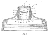
- each leg 33 includes a cleat 37 that will engage the inner edge of the side wall 20 when the valve member 14 is inserted into the central opening 18. In this position, shown in Figs. 5-6 , the inner ledge 31 engages the outer edge of the side wall 20, thereby securing the valve member 14 in the central opening 18.
- Each cleat 37 includes a beveled surface 39 that facilitates insertion of the valve member 14 into the central opening 18, as described below in more detail.
- the outer cover 30 is co-molded with the inner support 28 using a material having a lower hardness and increased elasticity compared to the inner support 28.
- the outer cover 30 is made from in elastomeric material having a durometer of about Shore A 50 and a tensile modulus of elasticity of about 5,516 kPa (800 psi). Co-molding the lower density outer cover 30 to the higher density inner support 28 decreases the number of parts required to seal the liquid-dispensing container against leaks, thereby increasing the durability of the valve member 14 of the illustrated embodiment in comparison with prior art valve members.
- the outer cover 30 includes an inner section 38 and an outer section 40 integrally formed with the inner section 38.
- the inner section 38 is engaged with and covers a relatively small part of the interior surface 34 of the upper end of the inner support 28.
- the inner section 38 includes an annular portion 42 that is engaged with and is secured to (e.g., co-molded with) the interior surface 34 of the inner support 28.
- the inner section 38 further includes a self-closing valve 44 supported by the annular portion 42 and substantially blocking the interior passage 36 through the inner support 28.
- the self-closing valve 44 includes slits 46 that defined four flaps that will open when sufficient pressure is applied to the valve 44. Self-closing valves of the type illustrated in the figures are well known in the field of water bottles.
- the outer section 40 includes an integral gasket 72 positioned between the inner ledge 31 and the cleats 37.
- the gasket 72 is dimensioned to contact and be compressed against the side wall 20 of the cap 16 in order to provide a watertight seal between the valve member 14 and the cap 16.
- valve member 14 In order to assemble the valve member 14 to the cap 16, the valve member 14 is aligned with the central opening 18 of the cap 16 and then the beveled surfaces 39 of the cleats 37 are brought into contact with the outer edge of the side wall 20 of the cap 16. Further movement of the valve member 14 toward the cap 16 results in the cleats 37 flexing slightly inward and/or the sidewall 20 flexing slightly outward to facilitate insertion of the valve member 14 into the central opening 18 of the cap 16. Eventually, the cleats 37 will pass and mechanically lock onto the inner edge of the side wall 20. In this position, the gasket 72 is deformed against the side wall 20 and the valve member 14 is secured in the central opening 18.
Landscapes
- Engineering & Computer Science (AREA)
- Mechanical Engineering (AREA)
- Closures For Containers (AREA)
Claims (7)
- Flüssigkeitsabgabebehälter, umfassend:ein Gehäuse (12), das dafür ausgelegt ist, eine Flüssigkeit in einem Innenvolumen aufzunehmen, wobei das Gehäuse (12) eine von einer Innenkante und einer Außenkante definierte Öffnung beinhaltet; undein Ventilelement (14) mit einem inneren Träger (28) und einer äußeren Abdeckung (30), die über dem inneren Träger (28) mitgeformt ist, wobei der innere Träger (28) eine röhrenförmige Struktur ist, die aus einem relativ steifen Plastikmaterial besteht und eine Länge aufweist, die sich über fast die gesamte Länge des Ventilelements (14) erstreckt, wobei der innere Träger (28) einen Absatz (31) aufweist, der die Außenkante in Eingriff nimmt, wobei der innere Träger (28) vier flexible Schenkel (33) beinhaltet, die durch Aussparungen (35) getrennt sind, wobei das Ende jedes Schenkels (33) eine Klemme (37) beinhaltet, wobei die Klemmen umfänglich voneinander beabstandet und von dem Absatz (31) beabstandet sind, wobei die Klemmen die Innenkante in Eingriff nehmen,
wobei der innere Träger (28) eine Außenfläche (32) und eine Innenfläche (34) beinhaltet, wobei die Innenfläche (34) einen inneren Durchgang (36) definiert, der sich den ganzen Weg durch das Ventilelement (14) erstreckt, wobei die äußere Abdeckung (30) einen inneren Abschnitt (38) und einen äußeren Abschnitt (40), der einstückig mit dem inneren Abschnitt (38) gebildet ist, beinhaltet, wobei der innere Abschnitt (38) mit einem relativ kleinen Teil der Innenfläche (34) des oberen Endes des inneren Trägers (28) in Eingriff steht und diesen abdeckt, wobei der innere Abschnitt (38) einen ringförmigen Teil (42) und ein selbstschließendes Ventil (44), das von dem ringförmigen Teil (42) getragen wird, beinhaltet, wobei das selbstschließende Ventil (44) Schlitze (46) beinhaltet, die vier Klappen definieren, die sich öffnen, wenn genügend Druck auf das Ventil (44) ausgeübt wird, und die den inneren Durchgang (36) durch den inneren Träger (28) im Wesentlichen blockieren, wobei der ringförmige Teil (42) mit der Innenfläche (34) des inneren Trägers (28) in Eingriff steht und daran gesichert ist;wobei die äußere Abdeckung (30) aus einem Material gebildet ist, das eine geringere Härte, geringere Dichte und erhöhte Elastizität im Vergleich zu dem Material aufweist, aus dem der innere Träger (28) besteht. - Flüssigkeitsabgabebehälter nach Anspruch 1, wobei das Gehäuse (12) eine Flasche (15) mit Außengewinde (17) und eine trennbare Kappe (16) mit Innengewinde (19), die auf die Flasche (15) geschraubt ist, beinhaltet.
- Flüssigkeitsabgabebehälter nach Anspruch 1, wobei die Innen- und Außenkante von einer Wand definiert sind und das Ventilelement (14) ferner eine integrale Dichtung (72) beinhaltet, die zwischen dem Absatz (31) und den Klemmen (37) positioniert ist, wobei die Dichtung (72) in Eingriff mit der Wand verformt wird.
- Flüssigkeitsabgabebehälter nach Anspruch 1, wobei jede Klemme (37) eine abgeschrägte Oberfläche (39) beinhaltet, die das Einsetzen des Ventilelements (14) in das Gehäuse (12) ermöglicht.
- Flüssigkeitsabgabebehälter nach Anspruch 1, wobei der innere Träger (28) aus einem Plastikmaterial mit einem Zug-E-Modul von 9.997.398 kPa (1.450.000 Pfund pro Quadratzoll) besteht.
- Flüssigkeitsabgabebehälter nach Anspruch 2, wobei die trennbare Kappe (16) eine zentrale Öffnung (18) beinhaltet, die von einer das Ventilelement (14) aufnehmenden Seitenwand (20) definiert ist.
- Verfahren zum Zusammenbauen eines Flüssigkeitsabgabebehälters nach Anspruch 1, wobei die Öffnung von einer Wand mit einer Innenkante und einer Außenkante definiert ist und das Ventilelement (14) an dem Gehäuse (12) gesichert ist, indem die Klemmen (37) mit der Außenkante der Wand in Eingriff gebracht werden, wobei das Verfahren umfasst: Inkontaktbringen der Klemmen mit der Außenkante der Wand, Bewegen des Ventilelements (14) hin zu dem Gehäuse (12), so dass die Klemmen (37) durch die Öffnung hindurchtritt, und Ineingriffbringen der Klemmen (37) mit der Innenkante der Wand.
Applications Claiming Priority (3)
| Application Number | Priority Date | Filing Date | Title |
|---|---|---|---|
| US201461934278P | 2014-01-31 | 2014-01-31 | |
| EP15743334.3A EP3099594A4 (de) | 2014-01-31 | 2015-01-29 | Wasserflasche mit selbstschliessendem ventil |
| PCT/US2015/013507 WO2015116809A1 (en) | 2014-01-31 | 2015-01-29 | Water bottle with self-closing valve |
Related Parent Applications (1)
| Application Number | Title | Priority Date | Filing Date |
|---|---|---|---|
| EP15743334.3A Division EP3099594A4 (de) | 2014-01-31 | 2015-01-29 | Wasserflasche mit selbstschliessendem ventil |
Publications (2)
| Publication Number | Publication Date |
|---|---|
| EP3409610A1 EP3409610A1 (de) | 2018-12-05 |
| EP3409610B1 true EP3409610B1 (de) | 2022-09-21 |
Family
ID=53757721
Family Applications (2)
| Application Number | Title | Priority Date | Filing Date |
|---|---|---|---|
| EP18184184.2A Active EP3409610B1 (de) | 2014-01-31 | 2015-01-29 | Wasserflasche mit selbstschliessendem ventil |
| EP15743334.3A Pending EP3099594A4 (de) | 2014-01-31 | 2015-01-29 | Wasserflasche mit selbstschliessendem ventil |
Family Applications After (1)
| Application Number | Title | Priority Date | Filing Date |
|---|---|---|---|
| EP15743334.3A Pending EP3099594A4 (de) | 2014-01-31 | 2015-01-29 | Wasserflasche mit selbstschliessendem ventil |
Country Status (5)
| Country | Link |
|---|---|
| US (1) | US10472140B2 (de) |
| EP (2) | EP3409610B1 (de) |
| CN (1) | CN106458382A (de) |
| TW (1) | TW201531430A (de) |
| WO (1) | WO2015116809A1 (de) |
Families Citing this family (13)
| Publication number | Priority date | Publication date | Assignee | Title |
|---|---|---|---|---|
| CN106458382A (zh) | 2014-01-31 | 2017-02-22 | 特制自行车配件有限公司 | 具有自闭阀的水瓶 |
| GB201517754D0 (en) * | 2015-10-07 | 2015-11-18 | Rieke Packaging Systems Ltd | Liquid dosing devices |
| US10358270B1 (en) | 2018-05-31 | 2019-07-23 | Camelbak Products, Llc | Closure assemblies and drink containers including the same |
| USD864658S1 (en) | 2018-05-31 | 2019-10-29 | Camelbak Products, Llc | Beverage container closure |
| US10532862B2 (en) | 2018-06-19 | 2020-01-14 | Camelbak Products, Llc | Closure assemblies with distinct dispensing modes and drink containers including the same |
| USD881639S1 (en) | 2018-06-19 | 2020-04-21 | Camelbak Products, Llc | Beverage container closure |
| TWI691440B (zh) * | 2019-05-21 | 2020-04-21 | 段睿紘 | 水壺或水杯的防水預力結構 |
| USD924059S1 (en) * | 2019-06-07 | 2021-07-06 | Hydrapak Llc | Bottle |
| US11511916B1 (en) * | 2020-01-29 | 2022-11-29 | Brandon Bernardo | Top closure assembly and drinking bottles including the same |
| US11912471B2 (en) | 2020-10-27 | 2024-02-27 | Yeti Coolers, Llc | Lid assembly for a container |
| USD957196S1 (en) | 2020-10-27 | 2022-07-12 | Yeti Coolers, Llc | Bottle |
| USD1015804S1 (en) | 2021-09-15 | 2024-02-27 | Yeti Coolers, Llc | Lid |
| USD999630S1 (en) * | 2022-01-24 | 2023-09-26 | Helen Of Troy Limited | Lid for a bottle |
Family Cites Families (78)
| Publication number | Priority date | Publication date | Assignee | Title |
|---|---|---|---|---|
| DE887771C (de) * | 1951-05-30 | 1953-08-27 | Werner Gienapp | Tube mit Verschluss |
| US3294294A (en) | 1964-12-08 | 1966-12-27 | Colgate Palmolive Co | Dispensing closure with slide |
| US3521796A (en) | 1968-06-10 | 1970-07-28 | Armstrong Cork Co | Sliding plunger dispensing closure |
| US3738545A (en) | 1971-03-12 | 1973-06-12 | Kerr Glass Mfg Corp | Sliding plunger dispensing closure |
| US4133446A (en) * | 1978-02-27 | 1979-01-09 | Thermo-Seal, Inc. | Drinking vessel cover with valve controlled openings |
| US4408702A (en) | 1981-11-06 | 1983-10-11 | William Horvath | Automatic dispenser cap |
| US5193264A (en) | 1988-02-08 | 1993-03-16 | Steelcase Inc. | In situ foam molding process and articles |
| US4925055A (en) * | 1988-03-04 | 1990-05-15 | Edward S. Robbins, III | Container with unitary bladder and associated dispenser cap |
| US4961888A (en) | 1988-07-28 | 1990-10-09 | Liquid Molding Systems, Inc. | Liquid silicone molding process |
| US5033655A (en) | 1989-02-15 | 1991-07-23 | Liquid Molding Systems Inc. | Dispensing package for fluid products and the like |
| US4991745A (en) | 1989-04-25 | 1991-02-12 | Liquid Molding Systems, Inc. | Dispensing valve with trampoline-like construction |
| US5213236A (en) | 1991-12-06 | 1993-05-25 | Liquid Molding Systems, Inc. | Dispensing valve for packaging |
| US5409144A (en) | 1991-12-06 | 1995-04-25 | Liquid Molding Systems Inc. | Dispensing valve for packaging |
| US5839614A (en) | 1991-12-06 | 1998-11-24 | Aptar Group, Inc. | Dispensing package |
| ES2079841T3 (es) | 1992-02-14 | 1996-01-16 | Procter & Gamble | Sistema que comprende un recipiente que tiene una valvula de hendidura en forma de valvula de ventilacion y un liquido contenido en dicho recipiente. |
| DE29513995U1 (de) | 1995-08-31 | 1995-11-16 | Koenighorst Bernd | Selbstschließender Verschluß |
| US5676289A (en) | 1996-04-04 | 1997-10-14 | Aptargroup, Inc. | Valve-controlled dispensing closure with dispersion baffle |
| DE19621676A1 (de) * | 1996-05-30 | 1997-12-11 | Zeller Plastik Koehn Graebner | Verschlußmembran |
| US5890621A (en) * | 1996-10-21 | 1999-04-06 | Gerber Products Company | Cup for young children with cap valved for fluid control |
| JP3523021B2 (ja) | 1997-06-20 | 2004-04-26 | 株式会社吉野工業所 | 容 器 |
| ID25801A (id) | 1997-08-21 | 2000-11-02 | Seaquist Closures | Bungkus penyalur dan metode untuk membuat bungkus penyalur |
| GB9802095D0 (en) * | 1998-01-30 | 1998-03-25 | Cannon Rubber Ltd | Closure assembly |
| US6045004A (en) | 1998-03-20 | 2000-04-04 | Aptargroup, Inc. | Dispensing structure with dispensing valve and barrier penetrator |
| US5971232A (en) | 1998-06-03 | 1999-10-26 | Aptargroup, Inc. | Dispensing structure which has a pressure-openable valve retained with folding elements |
| US6050451A (en) | 1998-11-19 | 2000-04-18 | Aptargroup, Inc. | Dispensing structure incorporating a valve-containing fitment for mounting to a container and a package with a dispensing structure |
| US6176474B1 (en) * | 1998-12-01 | 2001-01-23 | Emerson Electric Co. | Humidifier bottle with side fill/side dispensing cap |
| US6065642A (en) | 1998-12-09 | 2000-05-23 | Aptargroup, Inc. | Non-venting valve and dispensing package for fluid products and the like |
| DE29907933U1 (de) | 1999-05-04 | 1999-08-12 | Georg Menshen Gmbh & Co Kg | Schlitzschließventil für Behälteröffnungen |
| US6062435A (en) | 1999-05-06 | 2000-05-16 | Aptargroup, Inc. | Valved dispensing system with priming liquid loss prevention |
| DE19953706A1 (de) | 1999-07-05 | 2001-01-11 | Elvira Ahrens | Schlitzventil |
| US6769577B1 (en) | 1999-07-29 | 2004-08-03 | Weener Plastik Gmbh & Co. Kg | Self-closing valve |
| US6230940B1 (en) | 1999-11-02 | 2001-05-15 | Seaquist Closures Foreign, Inc. | One-Piece dispensing system and method for making same |
| EP1248735A2 (de) | 2000-01-17 | 2002-10-16 | Gabriel Bouzaglo | Dichtungsvorrichtung für behälter |
| US6257453B1 (en) | 2000-03-16 | 2001-07-10 | Owens-Illinois Closure Inc. | Tamper-indicating, two-piece dispensing closure |
| US6523711B1 (en) | 2000-04-13 | 2003-02-25 | Douglass E. Hughes | Automatic valved bottle cap for use with liquid containers |
| US20030222238A1 (en) * | 2001-02-07 | 2003-12-04 | Getzewich Lee A. | Bite valve for personal hydration devices and a method for making the same |
| US6938794B2 (en) | 2001-04-26 | 2005-09-06 | Innatech, Llc | Lip actuated valve closure for a drinking bottle |
| USH2027H1 (en) | 2001-06-06 | 2002-06-04 | Seaquist Closures Foreign, Inc. | Flexible slit valve |
| US6749092B2 (en) | 2001-08-10 | 2004-06-15 | Seaquist Closures Foreign, Inc. | Deformable dispensing valve |
| EP1467924A4 (de) * | 2001-12-18 | 2009-06-10 | Alto Holdings Ltd | Trinkverschluss mit hin- und herbewegbarer düse |
| US6910607B2 (en) | 2002-03-15 | 2005-06-28 | Crown Cork & Seal Technologies Corporation | Cover for dispensing closure with pressure actuated valve |
| DE10218363A1 (de) | 2002-04-25 | 2003-11-13 | Alpla Werke | Selbstschließendes Ventil |
| MXPA05002436A (es) | 2002-09-16 | 2005-05-27 | Alpla Werke | Valvula de membrana de cierre automatico. |
| US7070065B2 (en) * | 2004-03-10 | 2006-07-04 | Fu Hong Industries Limited | Closure assembly for drinking vessel |
| US7086572B2 (en) | 2004-03-26 | 2006-08-08 | Seaquist Closures Foreign, Inc. | Valve for dispensing product |
| US7077742B2 (en) | 2004-04-05 | 2006-07-18 | Trw Automotive U.S. Llc | Pressure relief valve and method of forming the same |
| US7243676B2 (en) | 2004-05-19 | 2007-07-17 | Vernay Laboratories, Inc. | Combination umbrella and inverted bi-directional valve |
| US7152763B2 (en) | 2004-07-08 | 2006-12-26 | Stull Technologies, Inc. | Container closure and method of assembly |
| NO321708B1 (no) * | 2004-09-09 | 2006-06-26 | Smartseal As | Hygienebevarende anordning ved en undertrykksaktivert ventil for en drikkebeholder |
| US7117654B2 (en) | 2004-12-29 | 2006-10-10 | Seaquist Closures Foreign, Inc. | Packaging process employing a closure orifice seal vent |
| US6951295B1 (en) * | 2005-01-18 | 2005-10-04 | Seaquist Closures Foreign, Inc. | Flow control element and dispensing structure incorporating same |
| GB2424871B (en) * | 2005-04-04 | 2009-01-28 | Garry Platt | Tamper-resistant bottle closure |
| WO2007016638A2 (en) | 2005-08-02 | 2007-02-08 | Prolabel | Beverage containers and accessories with integrated straw |
| JP2009505920A (ja) * | 2005-08-31 | 2009-02-12 | ガーバー プロダクツ カンパニー | 液漏れ防止閉蓋具 |
| US8557359B2 (en) | 2006-04-12 | 2013-10-15 | Abbott Laboratories | Closure for container |
| US7661560B2 (en) * | 2006-04-28 | 2010-02-16 | Pouch Pac Innovations, Llc | Flexible pouch with a tamper-evident outer cap fitment and method of forming |
| US7874466B2 (en) | 2006-11-07 | 2011-01-25 | The Procter & Gamble Company | Package comprising push-pull closure and slit valve |
| US20080110933A1 (en) | 2006-11-14 | 2008-05-15 | Goncalves Joao Alberto Ferreir | Tamper-indicating dispensing closure |
| EP1958883B8 (de) | 2007-02-14 | 2010-04-14 | Avesto Tech B.V. | Abgabeventil und damit ausgestatteter Behälter zum Aufnehmen einer Flüssigkeit |
| US8397956B2 (en) | 2007-03-27 | 2013-03-19 | Aptargroup, Inc. | Dispensing valve with improved dispensing |
| US7784652B2 (en) | 2007-03-27 | 2010-08-31 | Liquid Molding Systems, Inc. | Dispensing valve with hydraulic hammer resistance |
| US7874731B2 (en) | 2007-06-15 | 2011-01-25 | S.C. Johnson Home Storage, Inc. | Valve for a recloseable container |
| US20090188950A1 (en) * | 2008-01-25 | 2009-07-30 | Gaus David J | Valve for decorative dispensing |
| US8016507B2 (en) | 2008-02-06 | 2011-09-13 | Liquid Molding Systems, Inc. | Directional dispensing valve |
| US8678249B2 (en) | 2008-02-21 | 2014-03-25 | Aptargroup, Inc. | Valve mounting assembly with slit misalignment prevention feature |
| US8079385B2 (en) | 2008-04-09 | 2011-12-20 | Liquid Molding Systems, Inc. | Valve assembly |
| US8123087B2 (en) | 2008-07-21 | 2012-02-28 | Nike, Inc. | Container with extendable spout |
| US8316890B2 (en) | 2008-11-11 | 2012-11-27 | Aptargroup, Inc. | Port closure system with hydraulic hammer resistance |
| US8627852B2 (en) | 2009-01-22 | 2014-01-14 | Aptargroup, Inc. | Apertured flow control element and housing structure therefor |
| US8365941B2 (en) | 2009-05-15 | 2013-02-05 | David James Mayer | Dual-capped hydration bottle |
| US20100314418A1 (en) * | 2009-06-15 | 2010-12-16 | Donna Roth | Dispenser Adapted To Engage A Bottle And For Use With Consumable Fluid Having Solid Ingredients |
| WO2011025550A1 (en) * | 2009-08-31 | 2011-03-03 | Relaj, Inc. | Fluid container & support bracket therefor |
| CH704758A1 (de) | 2011-03-29 | 2012-10-15 | Medela Holding Ag | Saugnippeleinheit. |
| DE102011018822A1 (de) | 2011-04-27 | 2012-10-31 | Nürnberg Gummi Babyartikel GmbH & Co. KG | Trinkflasche |
| US20120273521A1 (en) | 2011-04-28 | 2012-11-01 | Race Wu | Liquid dispensing and sealing structure |
| US9060592B2 (en) | 2012-11-28 | 2015-06-23 | Specialized Bicycle Components, Inc. | Water bottle with poppet valve |
| CN106458382A (zh) | 2014-01-31 | 2017-02-22 | 特制自行车配件有限公司 | 具有自闭阀的水瓶 |
| AT516449B1 (de) * | 2014-11-13 | 2016-07-15 | Wieder Manuel | Verschluss für eine Trinkflasche |
-
2015
- 2015-01-29 CN CN201580012119.3A patent/CN106458382A/zh active Pending
- 2015-01-29 US US15/115,565 patent/US10472140B2/en active Active
- 2015-01-29 EP EP18184184.2A patent/EP3409610B1/de active Active
- 2015-01-29 EP EP15743334.3A patent/EP3099594A4/de active Pending
- 2015-01-29 WO PCT/US2015/013507 patent/WO2015116809A1/en active Application Filing
- 2015-01-30 TW TW104103300A patent/TW201531430A/zh unknown
Also Published As
| Publication number | Publication date |
|---|---|
| EP3099594A1 (de) | 2016-12-07 |
| EP3099594A4 (de) | 2018-01-24 |
| US20170166364A1 (en) | 2017-06-15 |
| EP3409610A1 (de) | 2018-12-05 |
| WO2015116809A1 (en) | 2015-08-06 |
| US10472140B2 (en) | 2019-11-12 |
| CN106458382A (zh) | 2017-02-22 |
| TW201531430A (zh) | 2015-08-16 |
Similar Documents
| Publication | Publication Date | Title |
|---|---|---|
| EP3409610B1 (de) | Wasserflasche mit selbstschliessendem ventil | |
| US9060592B2 (en) | Water bottle with poppet valve | |
| EP2771252B1 (de) | Flüssigkeitsausgabeanordnung | |
| US11358762B2 (en) | Container lid | |
| EP3209428B1 (de) | Pumpspender | |
| CN107720675B (zh) | 具有减压阀的容器 | |
| EP2704982B1 (de) | Befestigung eines anschlusstückes an einem behälter | |
| US20170027350A1 (en) | Lid for a drinking container and the drinking container | |
| RU2015120583A (ru) | Емкость для напитков и клапан для емкости для напитков | |
| US10390643B2 (en) | Refillable design for a closed water bottle | |
| WO2017199697A1 (ja) | キャップ及び吐出容器 | |
| US11014707B2 (en) | Resealable container | |
| EP3665098B1 (de) | Frontdruckknopfhahn | |
| US20160150899A1 (en) | Lid for a drinking container | |
| WO2011163219A1 (en) | Flow valve with integral spring and seal | |
| CN116495345A (zh) | 提升阀盖 | |
| KR200475950Y1 (ko) | 밀폐 마개 및 이를 이용한 저장 용기 | |
| KR20160039814A (ko) | 화장품 용기 | |
| JP2019123519A (ja) | キャップユニット及びキャップ付き容器 | |
| WO2012099669A1 (en) | Cap and spout assembly |
Legal Events
| Date | Code | Title | Description |
|---|---|---|---|
| PUAI | Public reference made under article 153(3) epc to a published international application that has entered the european phase |
Free format text: ORIGINAL CODE: 0009012 |
|
| STAA | Information on the status of an ep patent application or granted ep patent |
Free format text: STATUS: THE APPLICATION HAS BEEN PUBLISHED |
|
| AC | Divisional application: reference to earlier application |
Ref document number: 3099594 Country of ref document: EP Kind code of ref document: P |
|
| AK | Designated contracting states |
Kind code of ref document: A1 Designated state(s): AL AT BE BG CH CY CZ DE DK EE ES FI FR GB GR HR HU IE IS IT LI LT LU LV MC MK MT NL NO PL PT RO RS SE SI SK SM TR |
|
| STAA | Information on the status of an ep patent application or granted ep patent |
Free format text: STATUS: REQUEST FOR EXAMINATION WAS MADE |
|
| 17P | Request for examination filed |
Effective date: 20190530 |
|
| RBV | Designated contracting states (corrected) |
Designated state(s): AL AT BE BG CH CY CZ DE DK EE ES FI FR GB GR HR HU IE IS IT LI LT LU LV MC MK MT NL NO PL PT RO RS SE SI SK SM TR |
|
| STAA | Information on the status of an ep patent application or granted ep patent |
Free format text: STATUS: EXAMINATION IS IN PROGRESS |
|
| 17Q | First examination report despatched |
Effective date: 20200324 |
|
| STAA | Information on the status of an ep patent application or granted ep patent |
Free format text: STATUS: EXAMINATION IS IN PROGRESS |
|
| STAA | Information on the status of an ep patent application or granted ep patent |
Free format text: STATUS: EXAMINATION IS IN PROGRESS |
|
| GRAP | Despatch of communication of intention to grant a patent |
Free format text: ORIGINAL CODE: EPIDOSNIGR1 |
|
| STAA | Information on the status of an ep patent application or granted ep patent |
Free format text: STATUS: GRANT OF PATENT IS INTENDED |
|
| INTG | Intention to grant announced |
Effective date: 20220407 |
|
| RIN1 | Information on inventor provided before grant (corrected) |
Inventor name: JONES, RYAN, C. |
|
| GRAS | Grant fee paid |
Free format text: ORIGINAL CODE: EPIDOSNIGR3 |
|
| GRAA | (expected) grant |
Free format text: ORIGINAL CODE: 0009210 |
|
| STAA | Information on the status of an ep patent application or granted ep patent |
Free format text: STATUS: THE PATENT HAS BEEN GRANTED |
|
| AC | Divisional application: reference to earlier application |
Ref document number: 3099594 Country of ref document: EP Kind code of ref document: P |
|
| AK | Designated contracting states |
Kind code of ref document: B1 Designated state(s): AL AT BE BG CH CY CZ DE DK EE ES FI FR GB GR HR HU IE IS IT LI LT LU LV MC MK MT NL NO PL PT RO RS SE SI SK SM TR |
|
| REG | Reference to a national code |
Ref country code: GB Ref legal event code: FG4D |
|
| REG | Reference to a national code |
Ref country code: CH Ref legal event code: EP |
|
| REG | Reference to a national code |
Ref country code: IE Ref legal event code: FG4D |
|
| REG | Reference to a national code |
Ref country code: DE Ref legal event code: R096 Ref document number: 602015080938 Country of ref document: DE |
|
| REG | Reference to a national code |
Ref country code: AT Ref legal event code: REF Ref document number: 1519868 Country of ref document: AT Kind code of ref document: T Effective date: 20221015 |
|
| REG | Reference to a national code |
Ref country code: LT Ref legal event code: MG9D |
|
| REG | Reference to a national code |
Ref country code: NL Ref legal event code: MP Effective date: 20220921 |
|
| PG25 | Lapsed in a contracting state [announced via postgrant information from national office to epo] |
Ref country code: SE Free format text: LAPSE BECAUSE OF FAILURE TO SUBMIT A TRANSLATION OF THE DESCRIPTION OR TO PAY THE FEE WITHIN THE PRESCRIBED TIME-LIMIT Effective date: 20220921 Ref country code: RS Free format text: LAPSE BECAUSE OF FAILURE TO SUBMIT A TRANSLATION OF THE DESCRIPTION OR TO PAY THE FEE WITHIN THE PRESCRIBED TIME-LIMIT Effective date: 20220921 Ref country code: NO Free format text: LAPSE BECAUSE OF FAILURE TO SUBMIT A TRANSLATION OF THE DESCRIPTION OR TO PAY THE FEE WITHIN THE PRESCRIBED TIME-LIMIT Effective date: 20221221 Ref country code: LV Free format text: LAPSE BECAUSE OF FAILURE TO SUBMIT A TRANSLATION OF THE DESCRIPTION OR TO PAY THE FEE WITHIN THE PRESCRIBED TIME-LIMIT Effective date: 20220921 Ref country code: LT Free format text: LAPSE BECAUSE OF FAILURE TO SUBMIT A TRANSLATION OF THE DESCRIPTION OR TO PAY THE FEE WITHIN THE PRESCRIBED TIME-LIMIT Effective date: 20220921 Ref country code: FI Free format text: LAPSE BECAUSE OF FAILURE TO SUBMIT A TRANSLATION OF THE DESCRIPTION OR TO PAY THE FEE WITHIN THE PRESCRIBED TIME-LIMIT Effective date: 20220921 |
|
| REG | Reference to a national code |
Ref country code: AT Ref legal event code: MK05 Ref document number: 1519868 Country of ref document: AT Kind code of ref document: T Effective date: 20220921 |
|
| PG25 | Lapsed in a contracting state [announced via postgrant information from national office to epo] |
Ref country code: HR Free format text: LAPSE BECAUSE OF FAILURE TO SUBMIT A TRANSLATION OF THE DESCRIPTION OR TO PAY THE FEE WITHIN THE PRESCRIBED TIME-LIMIT Effective date: 20220921 Ref country code: GR Free format text: LAPSE BECAUSE OF FAILURE TO SUBMIT A TRANSLATION OF THE DESCRIPTION OR TO PAY THE FEE WITHIN THE PRESCRIBED TIME-LIMIT Effective date: 20221222 |
|
| PG25 | Lapsed in a contracting state [announced via postgrant information from national office to epo] |
Ref country code: SM Free format text: LAPSE BECAUSE OF FAILURE TO SUBMIT A TRANSLATION OF THE DESCRIPTION OR TO PAY THE FEE WITHIN THE PRESCRIBED TIME-LIMIT Effective date: 20220921 Ref country code: RO Free format text: LAPSE BECAUSE OF FAILURE TO SUBMIT A TRANSLATION OF THE DESCRIPTION OR TO PAY THE FEE WITHIN THE PRESCRIBED TIME-LIMIT Effective date: 20220921 Ref country code: PT Free format text: LAPSE BECAUSE OF FAILURE TO SUBMIT A TRANSLATION OF THE DESCRIPTION OR TO PAY THE FEE WITHIN THE PRESCRIBED TIME-LIMIT Effective date: 20230123 Ref country code: ES Free format text: LAPSE BECAUSE OF FAILURE TO SUBMIT A TRANSLATION OF THE DESCRIPTION OR TO PAY THE FEE WITHIN THE PRESCRIBED TIME-LIMIT Effective date: 20220921 Ref country code: CZ Free format text: LAPSE BECAUSE OF FAILURE TO SUBMIT A TRANSLATION OF THE DESCRIPTION OR TO PAY THE FEE WITHIN THE PRESCRIBED TIME-LIMIT Effective date: 20220921 Ref country code: AT Free format text: LAPSE BECAUSE OF FAILURE TO SUBMIT A TRANSLATION OF THE DESCRIPTION OR TO PAY THE FEE WITHIN THE PRESCRIBED TIME-LIMIT Effective date: 20220921 |
|
| PG25 | Lapsed in a contracting state [announced via postgrant information from national office to epo] |
Ref country code: SK Free format text: LAPSE BECAUSE OF FAILURE TO SUBMIT A TRANSLATION OF THE DESCRIPTION OR TO PAY THE FEE WITHIN THE PRESCRIBED TIME-LIMIT Effective date: 20220921 Ref country code: PL Free format text: LAPSE BECAUSE OF FAILURE TO SUBMIT A TRANSLATION OF THE DESCRIPTION OR TO PAY THE FEE WITHIN THE PRESCRIBED TIME-LIMIT Effective date: 20220921 Ref country code: IS Free format text: LAPSE BECAUSE OF FAILURE TO SUBMIT A TRANSLATION OF THE DESCRIPTION OR TO PAY THE FEE WITHIN THE PRESCRIBED TIME-LIMIT Effective date: 20230121 Ref country code: EE Free format text: LAPSE BECAUSE OF FAILURE TO SUBMIT A TRANSLATION OF THE DESCRIPTION OR TO PAY THE FEE WITHIN THE PRESCRIBED TIME-LIMIT Effective date: 20220921 |
|
| REG | Reference to a national code |
Ref country code: DE Ref legal event code: R097 Ref document number: 602015080938 Country of ref document: DE |
|
| PG25 | Lapsed in a contracting state [announced via postgrant information from national office to epo] |
Ref country code: NL Free format text: LAPSE BECAUSE OF FAILURE TO SUBMIT A TRANSLATION OF THE DESCRIPTION OR TO PAY THE FEE WITHIN THE PRESCRIBED TIME-LIMIT Effective date: 20220921 Ref country code: AL Free format text: LAPSE BECAUSE OF FAILURE TO SUBMIT A TRANSLATION OF THE DESCRIPTION OR TO PAY THE FEE WITHIN THE PRESCRIBED TIME-LIMIT Effective date: 20220921 |
|
| PLBE | No opposition filed within time limit |
Free format text: ORIGINAL CODE: 0009261 |
|
| STAA | Information on the status of an ep patent application or granted ep patent |
Free format text: STATUS: NO OPPOSITION FILED WITHIN TIME LIMIT |
|
| PG25 | Lapsed in a contracting state [announced via postgrant information from national office to epo] |
Ref country code: DK Free format text: LAPSE BECAUSE OF FAILURE TO SUBMIT A TRANSLATION OF THE DESCRIPTION OR TO PAY THE FEE WITHIN THE PRESCRIBED TIME-LIMIT Effective date: 20220921 |
|
| 26N | No opposition filed |
Effective date: 20230622 |
|
| PG25 | Lapsed in a contracting state [announced via postgrant information from national office to epo] |
Ref country code: SI Free format text: LAPSE BECAUSE OF FAILURE TO SUBMIT A TRANSLATION OF THE DESCRIPTION OR TO PAY THE FEE WITHIN THE PRESCRIBED TIME-LIMIT Effective date: 20220921 |
|
| REG | Reference to a national code |
Ref country code: CH Ref legal event code: PL |
|
| PG25 | Lapsed in a contracting state [announced via postgrant information from national office to epo] |
Ref country code: LU Free format text: LAPSE BECAUSE OF NON-PAYMENT OF DUE FEES Effective date: 20230129 |
|
| REG | Reference to a national code |
Ref country code: BE Ref legal event code: MM Effective date: 20230131 |
|
| PG25 | Lapsed in a contracting state [announced via postgrant information from national office to epo] |
Ref country code: LI Free format text: LAPSE BECAUSE OF NON-PAYMENT OF DUE FEES Effective date: 20230131 Ref country code: CH Free format text: LAPSE BECAUSE OF NON-PAYMENT OF DUE FEES Effective date: 20230131 |
|
| PG25 | Lapsed in a contracting state [announced via postgrant information from national office to epo] |
Ref country code: BE Free format text: LAPSE BECAUSE OF NON-PAYMENT OF DUE FEES Effective date: 20230131 |
|
| PGFP | Annual fee paid to national office [announced via postgrant information from national office to epo] |
Ref country code: GB Payment date: 20231207 Year of fee payment: 10 |
|
| PG25 | Lapsed in a contracting state [announced via postgrant information from national office to epo] |
Ref country code: IE Free format text: LAPSE BECAUSE OF NON-PAYMENT OF DUE FEES Effective date: 20230129 |
|
| PGFP | Annual fee paid to national office [announced via postgrant information from national office to epo] |
Ref country code: FR Payment date: 20231212 Year of fee payment: 10 |
|
| REG | Reference to a national code |
Ref country code: DE Ref legal event code: R082 Ref document number: 602015080938 Country of ref document: DE Representative=s name: FORRESTERS IP LLP, DE |
|
| PGFP | Annual fee paid to national office [announced via postgrant information from national office to epo] |
Ref country code: DE Payment date: 20231205 Year of fee payment: 10 |