EP3409524A1 - Air flow control device for an engine block in a motor vehicle - Google Patents
Air flow control device for an engine block in a motor vehicle Download PDFInfo
- Publication number
- EP3409524A1 EP3409524A1 EP17174396.6A EP17174396A EP3409524A1 EP 3409524 A1 EP3409524 A1 EP 3409524A1 EP 17174396 A EP17174396 A EP 17174396A EP 3409524 A1 EP3409524 A1 EP 3409524A1
- Authority
- EP
- European Patent Office
- Prior art keywords
- slats
- actuator
- lamellae
- air
- lamella
- Prior art date
- Legal status (The legal status is an assumption and is not a legal conclusion. Google has not performed a legal analysis and makes no representation as to the accuracy of the status listed.)
- Granted
Links
- 238000011144 upstream manufacturing Methods 0.000 claims abstract description 5
- 241000446313 Lamella Species 0.000 claims description 34
- 230000009975 flexible effect Effects 0.000 claims description 6
- 230000001276 controlling effect Effects 0.000 claims description 3
- 230000001105 regulatory effect Effects 0.000 claims description 2
- 238000000926 separation method Methods 0.000 claims description 2
- 239000003570 air Substances 0.000 description 46
- 238000001816 cooling Methods 0.000 description 3
- 238000009792 diffusion process Methods 0.000 description 3
- 238000009423 ventilation Methods 0.000 description 3
- 239000012080 ambient air Substances 0.000 description 2
- 230000004907 flux Effects 0.000 description 2
- 239000002826 coolant Substances 0.000 description 1
- 230000000694 effects Effects 0.000 description 1
- 239000000446 fuel Substances 0.000 description 1
- 239000013529 heat transfer fluid Substances 0.000 description 1
- 238000010438 heat treatment Methods 0.000 description 1
- 238000004519 manufacturing process Methods 0.000 description 1
- 238000013021 overheating Methods 0.000 description 1
- 230000005855 radiation Effects 0.000 description 1
Images

Classifications
-
- F—MECHANICAL ENGINEERING; LIGHTING; HEATING; WEAPONS; BLASTING
- F01—MACHINES OR ENGINES IN GENERAL; ENGINE PLANTS IN GENERAL; STEAM ENGINES
- F01P—COOLING OF MACHINES OR ENGINES IN GENERAL; COOLING OF INTERNAL-COMBUSTION ENGINES
- F01P11/00—Component parts, details, or accessories not provided for in, or of interest apart from, groups F01P1/00 - F01P9/00
- F01P11/10—Guiding or ducting cooling-air, to, or from, liquid-to-air heat exchangers
-
- B—PERFORMING OPERATIONS; TRANSPORTING
- B60—VEHICLES IN GENERAL
- B60K—ARRANGEMENT OR MOUNTING OF PROPULSION UNITS OR OF TRANSMISSIONS IN VEHICLES; ARRANGEMENT OR MOUNTING OF PLURAL DIVERSE PRIME-MOVERS IN VEHICLES; AUXILIARY DRIVES FOR VEHICLES; INSTRUMENTATION OR DASHBOARDS FOR VEHICLES; ARRANGEMENTS IN CONNECTION WITH COOLING, AIR INTAKE, GAS EXHAUST OR FUEL SUPPLY OF PROPULSION UNITS IN VEHICLES
- B60K11/00—Arrangement in connection with cooling of propulsion units
- B60K11/08—Air inlets for cooling; Shutters or blinds therefor
- B60K11/085—Air inlets for cooling; Shutters or blinds therefor with adjustable shutters or blinds
-
- B—PERFORMING OPERATIONS; TRANSPORTING
- B60—VEHICLES IN GENERAL
- B60K—ARRANGEMENT OR MOUNTING OF PROPULSION UNITS OR OF TRANSMISSIONS IN VEHICLES; ARRANGEMENT OR MOUNTING OF PLURAL DIVERSE PRIME-MOVERS IN VEHICLES; AUXILIARY DRIVES FOR VEHICLES; INSTRUMENTATION OR DASHBOARDS FOR VEHICLES; ARRANGEMENTS IN CONNECTION WITH COOLING, AIR INTAKE, GAS EXHAUST OR FUEL SUPPLY OF PROPULSION UNITS IN VEHICLES
- B60K11/00—Arrangement in connection with cooling of propulsion units
- B60K11/06—Arrangement in connection with cooling of propulsion units with air cooling
-
- F—MECHANICAL ENGINEERING; LIGHTING; HEATING; WEAPONS; BLASTING
- F01—MACHINES OR ENGINES IN GENERAL; ENGINE PLANTS IN GENERAL; STEAM ENGINES
- F01P—COOLING OF MACHINES OR ENGINES IN GENERAL; COOLING OF INTERNAL-COMBUSTION ENGINES
- F01P3/00—Liquid cooling
- F01P3/18—Arrangements or mounting of liquid-to-air heat-exchangers
-
- Y—GENERAL TAGGING OF NEW TECHNOLOGICAL DEVELOPMENTS; GENERAL TAGGING OF CROSS-SECTIONAL TECHNOLOGIES SPANNING OVER SEVERAL SECTIONS OF THE IPC; TECHNICAL SUBJECTS COVERED BY FORMER USPC CROSS-REFERENCE ART COLLECTIONS [XRACs] AND DIGESTS
- Y02—TECHNOLOGIES OR APPLICATIONS FOR MITIGATION OR ADAPTATION AGAINST CLIMATE CHANGE
- Y02T—CLIMATE CHANGE MITIGATION TECHNOLOGIES RELATED TO TRANSPORTATION
- Y02T10/00—Road transport of goods or passengers
- Y02T10/80—Technologies aiming to reduce greenhouse gasses emissions common to all road transportation technologies
- Y02T10/88—Optimized components or subsystems, e.g. lighting, actively controlled glasses
Definitions
- the invention also relates to a motor vehicle comprising such a device.
- This system makes it possible to control the flow of air towards the radiator by opening more or less the duct when cooling is necessary, and by closing it to stop the cooling, which makes it possible to reduce the time of heating of the motor during the start up and decrease fuel consumption, especially in winter.
- the air flow in the air duct is large enough to disrupt the flow of air to the point where it is discharged from the vehicle and create a force of air. noticeable drag that can slow down the vehicle. It is then useful to limit the flow of air in the duct by partially closing it.
- the flow control devices comprising rotating vanes are thus advantageous because they allow an improved control of the air flow reaching the radiator, since they can take several intermediate configurations between the total closure and the total opening.
- the opening and closing kinematics of such a fan blade device is complex, and requires the use of an actuator having oblong holes.
- an actuator having oblong holes.
- Such a piece is complex to make, and may be sensitive to use, the actuator may break or holes get dirty, which disrupts the proper operation of the device.
- An object of the invention is to effectively cool the vehicle engine without increasing the amount of air flowing through the flow control device, using a simple and robust piece to have an optimal longevity.
- the invention relates to a device of the aforementioned type, characterized in that each fastener is rotatably mounted solely on the actuator, about a respective actuating axis.
- Such a device makes it possible to have a more efficient diffusion of the flow of air passing through the ventilation duct, over the entire effective surface of the radiator located downstream, and thus to cool the motor more efficiently, while remaining simple to make and robust to use, since not requiring to articulate the fins in specific holes provided on the actuator.
- the invention also relates to a motor vehicle comprising a device as defined above, comprising a compartment, the compartment containing a motor and a radiator mounted on the engine, the compartment defining a conduit for conveying air up to to the radiator, the vehicle further comprising a device as defined above disposed across the conduit, regulating the flow of air through the conduit.
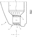
- a motor vehicle partially represented on the figure 1 , comprises a compartment 12 having a front face 14 and containing a motor equipped with a radiator 16.
- a motor equipped with a radiator 16 the terms “front”, “rear”, “high”, “Down”, “vertical”, “horizontal”, “transverse” and “longitudinal” with reference to the direction of normal movement of the motor vehicle 10 under usual conditions.
- the vehicle 10 is propelled by the engine, the latter generating heat during its operation.
- the radiator 16 is arranged in the vicinity of the engine, and a heat transfer fluid circulates between the engine and the radiator 16, to transmit the heat produced by the engine to the radiator 16.
- the radiator 16 removes some of the heat received in the ambient air , especially by convection and radiation.
- a duct 18 opens in the front face 14 and is arranged to convey the air through the compartment 12 to the radiator 16.
- a flow of air flows in the duct 18 under the effect of the convection having place around the radiator 16 which causes a draft.
- the flow rate of the air flow increases with the speed of the motor vehicle 10 when it moves.
- the duct 18 extends along an axis X-X 'longitudinal flow of air.
- the conduit 18 has for example a rectangular section. In what follows, the terms upstream and downstream will be used with respect to the direction of flow of the air flow in the duct 18, from the front face 14 to the radiator 16.
- a gate 20 extends across the conduit 18 at the front face 14, and a device 22 for controlling the air flow is installed in the conduit 18 downstream of the gate 20.
- the grid 20 comprises a plurality of bars 24 extending across the conduit 18, arranged to prevent bulky objects from entering the conduit 18 while allowing air to flow through the grid 20 from outside the vehicle. .
- the device 22 is adapted to control the flow of air flowing in the duct 18 towards the radiator 16.
- a first embodiment of the device 22 is shown in detail on the Figures 2 and 3 .
- the device 22 comprises a frame 30, a plurality of lamellae 32 arranged across the frame 30, and an actuator 34 of the lamellae 32.
- the device 22 comprises four identical strips 32.
- the device 22 comprises another number of lamellae 32, for example between two and twelve lamellae 32.
- the frame 30 is a substantially rectangular structure, which is extended along the walls of the duct 18 in a transverse plane YZ orthogonal to the air flow axis X-X '.
- the frame 30 defines an opening 36 of substantially rectangular section in the transverse plane YZ, so that the opening 36 extends through the frame 30 along the axis X-X 'of air flow.
- the lamellae 32 extend through the frame 30 in a transverse direction YY 'substantially orthogonal to the air flow axis X-X'.
- the slats 32 are arranged one above the other, aligned in a direction of elevation ZZ 'orthogonal to the air flow axis XX' and to the transverse direction Y-Y '.
- Each lamella 32 has one or two lamellae 32 adjacent, that is to say, located immediately above or below it.
- the transverse direction YY ' is for example horizontal and the elevation direction ZZ' is for example vertical.
- the plurality of lamellae 32 comprises a lower lamella 32 and at least one upper lamella 32, for example three upper lamellae 32 in the embodiment shown.
- the lower strip 32 is the strip 32 located lowest in the direction of elevation ZZ '.
- the upper slats 32 are the slats 32 located above the lower slat 32 in the elevation direction ZZ '.
- Each strip 32 extends in a deflection plane 38 of the respective air, along which the strip 32 redirects a portion of the air flow passing through the frame 30. Thus, when the air flow slides on the strip 32 he is reoriented according to the deflection plan 38.
- Each lamella 32 is rotatably mounted about a respective lamella axis 40 with respect to the frame 30.
- the actuator 34 is an elongate rod connected to each of the lamellae 32 by a fastener 41 projecting from the lamella 32.
- the actuator 34 is arranged to move the lamellae between a closed position represented on the figure 2 and an open position represented on the figure 3 .
- each slat 32 cooperate with each other to block the flow of air through the opening 36. That is to say in the closed position, each slat 32 is in contact with each lamella 32 adjacent, so as to prevent the passage of air between the two lamellae 32, and the lamellae 32 close the frame 30.
- the slats 32 allow the air to flow through the opening 36. That is to say in the open position, each slat 32 is away from each slat 32 adjacent, so as to leave free a space of air flow between the two strips 32.
- the actuator 34 is articulated to each blade 32 by a pivot connection located at one end of the fastener 41, about a respective actuating axis 42.
- the articulation of the fastener 41 on the actuator 34 is solely in rotation about the actuating axis 42.
- the actuating axis 42 is not mobile in translation with respect to the actuator 34.
- the actuating axis 42 is shifted with respect to the slat axis 40 so that a longitudinal translation of the actuator 34 causes the rotation of each slat 32 about its respective slat axis 40.
- the actuating axis 42 and the lamella axis 40 are parallel to each other and separated by a distance e.
- each upper lamella 32 is greater than the distance e of the lamella 32 situated directly below, as can be seen in FIG. figure 2 .
- the slats 32 are arranged, when in the open position, to diffuse the air flow towards the radiator 16.
- the plane of deflection 38 of the slats 32 are not parallel, but intersect each other upstream of the frame 30, so that the slats 32 are fan-shaped in the open position.
- the deflection plane of the lower strip 32 forms a right angle with the transverse plane YZ
- the deflection planes of the upper plates 32 form non-right angles with the transverse plane YZ.
- each deflection plane 38 intersects the deflection plane (s) 38 of the adjacent lamellae 32 at the same spacing angle ⁇ .
- the angle of separation ⁇ is between 5 ° and 20 °, in particular equal to 10 °.
- the actuator 34 is adapted to deform during the passage of the slats 32 from the closed position to the open position.
- the arrangement of the slats 32 in the open position and the linear nature of the actuator 34 make the kinematics of passage from the closed position to the hyperstatic opening position.
- the flexibility of the actuator 34 overcomes this problem without resorting to more complex systems such as those with oblong holes.
- the actuator 34 is for example a bar comprising flexible sections 44 along its length, to allow easier deformation.
- the flexible sections 44 are for example located at the axes of actuation 42 of some of the lamellae 32, for example at the second and third lamella 32 in the example shown in FIGS. Figures 2 and 3 .
- the flexible sections 44 have for example a reduced section, made by means of a notch or groove in the structure of the actuator 34.
- the actuator 34 extends substantially rectilinearly when the slats 32 are in the closed position and extends along a curved line when the slats 32 are in the open position.
- the actuating axes 42 of the slats 32 are aligned in the elevation direction ZZ 'when the slats 32 are in the closed position, and arranged along the curved line when the slats 32 are in the open position.
- the actuating axes 42 are not aligned in an XZ plane orthogonal to the lamellae axes 40, when the lamellae 32 are in the open position.
- the curved line is for example an arc of a circle.
- the actuating axes 42 of the second and third lamella 32 are offset downstream by the deformation of the actuator 34, when the lamellae 32 are in the open position. That is to say that the actuating axes 42 of the second and third lamella 32 are located at a non-zero distance, for example between 0.2 mm and 0.4 mm, from the straight line by the actuating axes 42 of the first and fourth lamellae 32.
- the actuator 34 extends substantially rectilinear and parallel to the transverse plane YZ when the slats 32 are in the open position, and along the curved line when the slats 32 are in the closed position, the curved line intersecting the transverse plane at an angle of inclination ⁇ non-zero, in particular between 3 ° and 15 °.
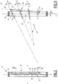
- the actuator 34 does not deform significantly during the passage of the slats 32 of the closed position shown on the figure 4 at the open position shown on the figure 5 .
- the lamellae axes 40 are not aligned in a direction parallel to the transverse plane YZ, but are arranged in a curved line, with for example the lamellae axes 40 of the second and third lamellae 32 located further downstream than the lamellae axes 40 of the first and fourth lamellae 32.
- actuating axes 42 of the slats 32 are arranged in the same curved line, moved in translation when the slats 32 pass from the open position to the closed position and vice versa. That is to say that each of the actuating axes 42 follows the same translation when the slats 32 are moved from the open position to the closed position or vice versa.
- the actuator 34 comprises a main section 45 and a plurality of secondary sections 46 connected substantially orthogonal to the main section 45 by a first end.
- the secondary sections 46 are articulated to the fasteners 41 at their other end, around the actuating axes 42.
- the secondary sections 46 have different lengths from each other.
- the main section 45 extends substantially parallel to the transverse plane YZ, and the secondary sections 46 extend substantially orthogonal to the transverse plane YZ, when the slats 32 are in the closed position and when they are in the open position.
- the device 22 described makes it possible to have a more effective diffusion of the air flow passing through the duct 18, over the entire effective surface of the radiator 16 located downstream, and thus to cool the motor more efficiently.
- the device 22 remains simple to manufacture and robust to use, particularly thanks to the shape and flexibility of the actuator 34.
Landscapes
- Engineering & Computer Science (AREA)
- Chemical & Material Sciences (AREA)
- Combustion & Propulsion (AREA)
- Mechanical Engineering (AREA)
- Transportation (AREA)
- General Engineering & Computer Science (AREA)
- Cooling, Air Intake And Gas Exhaust, And Fuel Tank Arrangements In Propulsion Units (AREA)
Abstract
L'invention concerne un dispositif (22) comprenant :
- un cadre (30) définissant une ouverture (36) ;
- une pluralité de lamelles (32) s'étendant en travers du cadre (30), disposées les unes au-dessus des autres ; et
- un actionneur (34) relié à chacune des lamelles (32) par une attache (41) respective.The invention relates to a device (22) comprising:
- a frame (30) defining an opening (36);
a plurality of lamellae (32) extending across the frame (30), arranged one above the other; and
an actuator (34) connected to each of the slats (32) by a respective fastener (41).
Chaque lamelle (32) s'étend dans un plan de déflexion (38) de l'air respectif, et est déplaçable au moyen de l'actionneur (34), entre :
- une position de fermeture, dans laquelle les lamelles (32) coopèrent entre elles pour bloquer le passage de l'air à travers l'ouverture (36), et
- une position d'ouverture, dans laquelle les lamelles (32) laissent l'air s'écouler à travers l'ouverture (36), les plans de déflexion (38) des lamelles (32) s'intersectant en amont du cadre (30).Each strip (32) extends in a plane of deflection (38) of the respective air, and is displaceable by means of the actuator (34), between:
a closing position in which the lamellae (32) cooperate with one another to block the passage of air through the opening (36), and
an opening position in which the slats (32) allow the air to flow through the opening (36), the deflection planes (38) of the slats (32) intersecting upstream of the frame ( 30).
Chaque attache (41) est montée de manière mobile en rotation uniquement sur l'actionneur (34), autour d'un axe d'actionnement (42) respectif.

Description
La présente invention concerne un dispositif de contrôle d'un flux d'air dans un compartiment de véhicule automobile, le dispositif comprenant :
- au moins un cadre définissant une ouverture, le cadre s'étendant dans un plan transverse, l'ouverture s'étendant selon un axe d'écoulement de l'air sensiblement perpendiculaire au plan transverse ;
- une pluralité de lamelles s'étendant en travers du cadre, les lamelles étant disposées les unes au-dessus des autres ; et
- un actionneur relié à chacune des lamelles par une attache respective ;
- une position de fermeture, dans laquelle les lamelles coopèrent entre elles pour bloquer le passage de l'air à travers l'ouverture, et
- une position d'ouverture, dans laquelle les lamelles laissent l'air s'écouler à travers l'ouverture, et dans laquelle les plans de déflexion des lamelles s'intersectent les uns les autres en amont du
cadre 30 par rapport à l'axe d'écoulement du flux d'air.
- at least one frame defining an opening, the frame extending in a transverse plane, the opening extending along an air flow axis substantially perpendicular to the transverse plane;
- a plurality of lamellae extending across the frame, the lamellae being arranged one above the other; and
- an actuator connected to each of the slats by a respective fastener;
- a closed position in which the lamellae cooperate with each other to block the passage of air through the opening, and
- an open position, in which the lamellae allow air to flow through the aperture, and in which the deflection planes of the lamellae intersect each other upstream of the
frame 30 with respect to the axis flow of the air flow.
L'invention concerne également un véhicule automobile comprenant un tel dispositif.The invention also relates to a motor vehicle comprising such a device.
Il est nécessaire pour le bon fonctionnement des véhicules automobiles de refroidir le moteur afin d'éviter qu'il surchauffe. Pour cela, la plupart des véhicules comprennent un conduit d'aération s'ouvrant sur la face avant et acheminant de l'air environnant jusqu'à un radiateur. Le flux d'air refroidit un liquide caloporteur circulant dans le radiateur et le moteur, dissipant une partie de la chaleur produite par le moteur.It is necessary for the proper functioning of motor vehicles to cool the engine to prevent it from overheating. For this, most vehicles include a ventilation duct opening on the front and conveying ambient air to a radiator. The airflow cools a coolant circulating in the radiator and the engine, dissipating some of the heat generated by the engine.
Afin de contrôler le refroidissement de manière optimale, il est connu d'utiliser un système de fermeture et d'ouverture du conduit d'aération, comportant par exemple des ailettes inclinables.In order to control the cooling optimally, it is known to use a system for closing and opening the ventilation duct, comprising, for example, tilting fins.
Ce système permet de contrôler le flux d'air allant vers le radiateur en ouvrant plus ou moins le conduit lorsqu'un refroidissement est nécessaire, et en le fermant pour stopper le refroidissement, ce qui permet de réduire le temps de chauffe du moteur lors du démarrage et de diminuer la consommation de carburant, notamment en hiver.This system makes it possible to control the flow of air towards the radiator by opening more or less the duct when cooling is necessary, and by closing it to stop the cooling, which makes it possible to reduce the time of heating of the motor during the start up and decrease fuel consumption, especially in winter.
De plus, lorsque la vitesse du véhicule est importante, le flux d'air dans le conduit d'aération est suffisamment important pour perturber l'écoulement de l'air à l'endroit où il est évacué hors du véhicule et créer une force de traînée notable qui peut ralentir le véhicule. Il est alors utile de limiter le flux d'air dans le conduit en le fermant partiellement.In addition, when the vehicle speed is high, the air flow in the air duct is large enough to disrupt the flow of air to the point where it is discharged from the vehicle and create a force of air. noticeable drag that can slow down the vehicle. It is then useful to limit the flow of air in the duct by partially closing it.
Les dispositifs de contrôle du flux comprenant des ailettes mobiles en rotation sont ainsi avantageux car ils permettent un contrôle amélioré du flux d'air atteignant le radiateur, puisqu'ils peuvent prendre plusieurs configurations intermédiaires entre la fermeture totale et l'ouverture totale.The flow control devices comprising rotating vanes are thus advantageous because they allow an improved control of the air flow reaching the radiator, since they can take several intermediate configurations between the total closure and the total opening.
Il est connu, par exemple du document
Ces dispositifs peuvent encore être améliorés. En effet, la cinématique d'ouverture et de fermeture d'un tel dispositif à lamelles en éventail est complexe, et nécessite l'utilisation d'un actionneur présentant des trous oblongs. Une telle pièce est complexe à confectionner, et peut se révéler sensible à l'utilisation, l'actionneur pouvant se briser ou les orifices s'encrasser, ce qui perturbe le bon fonctionnement du dispositif.These devices can be further improved. Indeed, the opening and closing kinematics of such a fan blade device is complex, and requires the use of an actuator having oblong holes. Such a piece is complex to make, and may be sensitive to use, the actuator may break or holes get dirty, which disrupts the proper operation of the device.
Un but de l'invention est de refroidir efficacement le moteur du véhicule sans pour autant augmenter la quantité d'air circulant à travers le dispositif de contrôle du flux, en utilisant une pièce simple et robuste pour présenter une longévité optimale.An object of the invention is to effectively cool the vehicle engine without increasing the amount of air flowing through the flow control device, using a simple and robust piece to have an optimal longevity.
A cet effet, l'invention a pour objet un dispositif du type précité, caractérisé en ce que chaque attache est montée de manière mobile en rotation uniquement sur l'actionneur, autour d'un axe d'actionnement respectif.For this purpose, the invention relates to a device of the aforementioned type, characterized in that each fastener is rotatably mounted solely on the actuator, about a respective actuating axis.
Un tel dispositif permet d'avoir une diffusion plus efficace du flux d'air traversant le conduit d'aération, sur l'ensemble de la surface efficace du radiateur situé en aval, et ainsi de refroidir le moteur plus efficacement, tout en restant simple à confectionner et robuste à l'usage, puisque ne nécessitant pas d'articuler les ailettes dans des trous spécifiques prévus sur l'actionneur.Such a device makes it possible to have a more efficient diffusion of the flow of air passing through the ventilation duct, over the entire effective surface of the radiator located downstream, and thus to cool the motor more efficiently, while remaining simple to make and robust to use, since not requiring to articulate the fins in specific holes provided on the actuator.
Selon des modes de réalisation alternatifs, le dispositif selon l'invention présente l'une ou plusieurs des caractéristiques suivantes, prise(s) individuellement ou selon toute combinaison techniquement possible :
- les axes d'actionnement des lamelles sont disposés sur une ligne courbe au moins lorsque les lamelles sont en position d'ouverture ;
- lorsque les lamelles sont en position de fermeture, l'actionneur s'étend de manière sensiblement rectiligne, et lorsque les lamelles sont en position d'ouverture, l'actionneur s'étend selon une ligne courbe ;
- l'actionneur est une barrette comprenant des tronçons flexibles ;
- les axes d'actionnement des lamelles sont disposés sur une ligne courbe, déplacée en translation lorsque les lamelles se déplacent entre la position de fermeture et la position d'ouverture ;
- l'actionneur comprend au moins deux tronçons de longueurs différentes, chaque tronçon présentant une extrémité liée à une des attaches ;
- la pluralité de lamelles comprend une lamelle inférieure, le plan de déflexion de la lamelle inférieure formant un angle sensiblement droit avec le plan transverse, lorsque la lamelle inférieure est en position d'ouverture, la pluralité de lamelles comprenant en outre au moins une lamelle supérieure, le plan de déflexion de chaque lamelle supérieure formant un angle non-droit avec le plan transverse, lorsque la lamelle supérieure est en position d'ouverture ;
- le plan de déflexion de chaque lamelle supérieure forme un même angle d'écartement avec le plan de déflexion de la lamelle située directement en dessous ; et
- chaque lamelle présente une distance d'écart non nulle entre l'axe de lamelle et l'axe d'actionnement, la distance d'écart de chaque lamelle étant plus importante que la distance d'écart de la lamelle située directement en-dessous.
- the axes of actuation of the slats are arranged on a curved line at least when the slats are in the open position;
- when the slats are in the closed position, the actuator extends substantially rectilinearly, and when the slats are in the open position, the actuator extends along a curved line;
- the actuator is a bar comprising flexible sections;
- the actuating axes of the slats are arranged on a curved line displaced in translation when the slats move between the closed position and the open position;
- the actuator comprises at least two sections of different lengths, each section having an end connected to one of the fasteners;
- the plurality of lamellae comprises a lower lamella, the deflection plane of the lower lamella forming a substantially straight angle with the transverse plane, when the lower lamella is in the open position, the plurality of lamellae further comprising at least one upper lamella the deflection plane of each upper lamella forming a non-straight angle with the transverse plane, when the upper lamella is in the open position;
- the deflection plane of each upper lamella forms the same spacing angle with the plane of deflection of the lamella located directly below; and
- each lamella has a distance of non-zero gap between the lamella axis and the actuating axis, the spacing distance of each lamella being greater than the distance of the lamella located directly below.
L'invention a également pour objet un véhicule automobile comprenant un dispositif tel que défini plus haut, comprenant un compartiment, le compartiment contenant un moteur et un radiateur monté sur le moteur, le compartiment définissant un conduit d'acheminement de l'air jusqu'au radiateur, le véhicule comprenant de plus un dispositif tel que défini ci-dessus disposé en travers du conduit, régulant le flux d'air à travers le conduit.The invention also relates to a motor vehicle comprising a device as defined above, comprising a compartment, the compartment containing a motor and a radiator mounted on the engine, the compartment defining a conduit for conveying air up to to the radiator, the vehicle further comprising a device as defined above disposed across the conduit, regulating the flow of air through the conduit.
L'invention sera mieux comprise à la lecture de la description qui suit, donnée uniquement à titre d'exemple, et faite en référence aux dessins annexés, parmi lesquels :
- la
figure 1 est une vue en coupe d'un bloc avant d'un véhicule automobile comprenant un dispositif de contrôle du flux d'air selon un mode de réalisation de l'invention ; - la
figure 2 est une vue en coupe détaillée du dispositif de contrôle de lafigure 1 , lorsque des ailettes sont en position de fermeture ; - la
figure 3 est une vue en coupe détaillée du dispositif de contrôle desfigures 1 et2 , lorsque des ailettes sont en position d'ouverture ; et - les
figures 4 et 5 sont des vues en coupe détaillée d'un autre mode de réalisation du dispositif selon l'invention, respectivement en position de fermeture et d'ouverture.
- the
figure 1 is a sectional view of a front block of a motor vehicle comprising an airflow control device according to one embodiment of the invention; - the
figure 2 is a detailed sectional view of the control device of thefigure 1 when fins are in the closed position; - the
figure 3 is a detailed sectional view of the control device of thefigures 1 and2 when fins are in the open position; and - the
Figures 4 and 5 are detailed sectional views of another embodiment of the device according to the invention, respectively in the closed position and opening.
Un véhicule 10 automobile, partiellement représenté sur la
Le véhicule 10 est propulsé par le moteur, ce dernier générant de la chaleur au cours de son fonctionnement.The
Le radiateur 16 est disposé au voisinage du moteur, et un fluide caloporteur circule entre le moteur et le radiateur 16, pour transmettre la chaleur produite par le moteur au radiateur 16. Le radiateur 16 élimine une partie de la chaleur reçue dans l'air ambiant, notamment par convection et par rayonnement.The
Un conduit 18 s'ouvre dans la face avant 14 et est agencé pour acheminer l'air à travers le compartiment 12 jusqu'au radiateur 16. Un flux d'air s'écoule dans le conduit 18 sous l'effet de la convection ayant lieu autour du radiateur 16 qui provoque un appel d'air. Le débit du flux d'air augmente avec la vitesse du véhicule automobile 10 lorsque celui-ci se déplace.A
Le conduit 18 s'étend selon un axe X-X' longitudinal d'écoulement de l'air. Le conduit 18 présente par exemple une section rectangulaire. Dans tout ce qui suit, on utilisera les termes d'amont et d'aval par rapport au sens d'écoulement du flux d'air dans le conduit 18, depuis la face avant 14 vers le radiateur 16.The
Une grille 20 s'étend en travers du conduit 18 au niveau de la face avant 14, et un dispositif 22 de contrôle du flux d'air est installé dans le conduit 18 en aval de la grille 20.A
La grille 20 comprend une pluralité de barreaux 24 s'étendant en travers du conduit 18, agencés pour empêcher des objets volumineux de pénétrer dans le conduit 18 tout en laissant l'air s'écouler à travers la grille 20 depuis l'extérieur du véhicule.The
Le dispositif 22 est adapté pour contrôler le flux d'air s'écoulant dans le conduit 18 en direction du radiateur 16. Un premier mode de réalisation du dispositif 22 est représenté en détail sur les
Le dispositif 22 comprend un cadre 30, une pluralité de lamelles 32 disposées en travers du cadre 30, et un actionneur 34 des lamelles 32. Dans l'exemple représenté, le dispositif 22 comprend quatre lamelles 32 identiques. En variante, le dispositif 22 comprend un autre nombre de lamelles 32, par exemple entre deux et douze lamelles 32.The
Le cadre 30 est une structure sensiblement rectangulaire, qui est s'étend le long des parois du conduit 18 selon un plan transverse YZ orthogonal à l'axe d'écoulement de l'air X-X'. Le cadre 30 définit une ouverture 36 de section sensiblement rectangulaire dans le plan transverse YZ, de sorte que l'ouverture 36 s'étend à travers le cadre 30, selon l'axe X-X' d'écoulement de l'air.The
Les lamelles 32 s'étendent à travers le cadre 30 selon une direction transversale Y-Y' sensiblement orthogonale à l'axe d'écoulement de l'air X-X'. Les lamelles 32 sont disposées les unes au-dessus des autres, alignées selon une direction d'élévation Z-Z' orthogonale à l'axe d'écoulement de l'air X-X' et à la direction transversale Y-Y'. Chaque lamelle 32 a une ou deux lamelles 32 voisines, c'est-à-dire situées immédiatement au-dessus ou au-dessous d'elle. La direction transversale Y-Y' est par exemple horizontale et la direction d'élévation Z-Z' est par exemple verticale.The
La pluralité de lamelles 32 comprend une lamelle 32 inférieure et au moins une lamelle 32 supérieure, par exemple trois lamelles 32 supérieures dans le mode de réalisation représenté. La lamelle 32 inférieure est la lamelle 32 située le plus bas selon la direction d'élévation Z-Z'. Les lamelles 32 supérieures sont les lamelles 32 situées au-dessus de la lamelle 32 inférieure selon la direction d'élévation Z-Z'.The plurality of
Chaque lamelle 32 s'étend dans un plan de déflexion 38 de l'air respectif, le long duquel la lamelle 32 redirige une partie du flux d'air traversant le cadre 30. Ainsi, lorsque le flux d'air glisse sur la lamelle 32, il est réorienté selon le plan de déflexion 38.Each
Chaque lamelle 32 est montée mobile en rotation autour d'un axe de lamelle 40 respectif par rapport au cadre 30.Each
L'actionneur 34 est une bielle allongée liée à chacune des lamelles 32 par une attache 41, faisant saillie depuis la lamelle 32. L'actionneur 34 est agencé pour déplacer les lamelles entre une position de fermeture représentée sur la
Dans la position de fermeture, les lamelles 32 coopèrent entre elles pour bloquer l'écoulement de l'air à travers l'ouverture 36. C'est-à-dire qu'en position de fermeture, chaque lamelle 32 est en contact avec chaque lamelle 32 voisine, de façon à empêcher le passage de l'air entre les deux lamelles 32, et les lamelles 32 ferment le cadre 30.In the closed position, the
Dans la position d'ouverture, les lamelles 32 laissent l'air s'écouler à travers l'ouverture 36. C'est-à-dire qu'en position d'ouverture, chaque lamelle 32 est à l'écart de chaque lamelle 32 voisine, de façon à laisser libre un espace d'écoulement de l'air entre les deux lamelles 32.In the open position, the
L'actionneur 34 est articulé à chaque lamelle 32 par une liaison pivot située à une extrémité de l'attache 41, autour d'un axe d'actionnement 42 respectif. L'articulation de l'attache 41 sur l'actionneur 34 se fait uniquement en rotation autour de l'axe d'actionnement 42. On entend par là que l'axe d'actionnement 42 n'est pas mobile en translation par rapport à l'actionneur 34.The
L'axe d'actionnement 42 est décalé par rapport à l'axe de lamelle 40 de sorte qu'une translation longitudinale de l'actionneur 34 entraîne la rotation de chaque lamelle 32 autour de son axe de lamelle 40 respectif. L'axe d'actionnement 42 et l'axe de lamelle 40 sont parallèles entre eux, et séparés d'une distance d'écart e.The actuating
La distance d'écart e de chaque lamelle 32 supérieure est plus importante que la distance d'écart e de la lamelle 32 située directement en-dessous, comme cela est visible sur la
Les lamelles 32 sont agencées, lorsqu'elles sont en position d'ouverture, pour diffuser le flux d'air en direction du radiateur 16. Le plan de déflexion 38 des lamelles 32 ne sont pas parallèles, mais s'intersectent les uns les autres en amont du cadre 30, de sorte que les lamelles 32 sont disposées en éventail en position d'ouverture.The
Dans l'exemple représenté, le plan de déflexion de la lamelle 32 inférieure forme un angle droit avec le plan transverse YZ, et les plans de déflexion des lamelles 32 supérieures forment des angles non-droits avec le plan transverse YZ.In the example shown, the deflection plane of the
Avantageusement, chaque plan de déflexion 38 intersecte le ou les plans de déflexion 38 des lamelles 32 voisines selon un même angle d'écartement α. Par exemple, l'angle d'écartement α est compris entre 5° et 20°, notamment égal à 10°.Advantageously, each
Dans le premier mode de réalisation des
En effet, l'agencement des lamelles 32 en position d'ouverture et le caractère linéaire de l'actionneur 34 rendent la cinématique de passage de la position de fermeture à la position d'ouverture hyperstatique. La flexibilité de l'actionneur 34 permet de pallier ce problème sans avoir recours à des systèmes plus complexes comme ceux comportant des trous oblongs.Indeed, the arrangement of the
L'actionneur 34 est par exemple une barrette comprenant des tronçons flexibles 44 le long de son étendue, pour permettre une déformation plus facile. Les tronçons flexibles 44 sont par exemple situés au niveau des axes d'actionnement 42 de certaines des lamelles 32, par exemple au niveau de la deuxième et de la troisième lamelle 32 dans l'exemple représenté sur les
Les tronçons flexibles 44 présentent par exemple une section réduite, réalisée au moyen d'une encoche ou d'une gorge dans la structure de l'actionneur 34.The
L'actionneur 34 s'étend de manière sensiblement rectiligne lorsque les lamelles 32 sont en position de fermeture et s'étend selon une ligne courbe lorsque les lamelles 32 sont en position d'ouverture.The
Ainsi, les axes d'actionnement 42 des lamelles 32 sont alignés selon la direction d'élévation Z-Z' lorsque les lamelles 32 sont en position de fermeture, et disposés suivant la ligne courbe lorsque les lamelles 32 sont en position d'ouverture. Par cela, on entend que les axes d'actionnement 42 ne sont pas alignés dans un plan XZ orthogonal aux axes de lamelle 40, lorsque les lamelles 32 sont en position d'ouverture.Thus, the actuating axes 42 of the
La ligne courbe est par exemple un arc de cercle.The curved line is for example an arc of a circle.
Dans l'exemple représenté, les axes d'actionnement 42 de la deuxième et de la troisième lamelle 32 sont décalés vers l'aval par la déformation de l'actionneur 34, lorsque les lamelles 32 sont en position d'ouverture. C'est-à-dire que les axes d'actionnement 42 de la deuxième et de la troisième lamelle 32 sont situés à une distance non-nulle, par exemple comprise entre 0,2 mm et 0,4 mm, de la droite passant par les axes d'actionnement 42 de la première et de la quatrième lamelle 32.In the example shown, the actuating axes 42 of the second and
Dans ce mode de réalisation, l'actionneur 34 s'étend de manière sensiblement rectiligne et parallèle au plan transverse YZ lorsque les lamelles 32 sont en position d'ouverture, et selon la ligne courbe lorsque les lamelles 32 sont en position de fermeture, la ligne courbe intersectant le plan transverse selon un angle d'inclinaison γ non nul, notamment compris entre 3° et 15°.In this embodiment, the
Un deuxième mode de réalisation du dispositif 22, représenté sur les
Dans le deuxième mode de réalisation, l'actionneur 34 ne se déforme pas notablement lors du passage des lamelles 32 de la position de fermeture représentée sur la
Dans le deuxième mode de réalisation, les axes de lamelle 40 ne sont pas alignés selon une direction parallèle au plan transverse YZ, mais sont disposés selon une ligne courbe, avec par exemple les axes de lamelle 40 de la deuxième et de la troisième lamelle 32 situés plus en aval que les axes de lamelle 40 de la première et de la quatrième lamelle 32.In the second embodiment, the lamellae axes 40 are not aligned in a direction parallel to the transverse plane YZ, but are arranged in a curved line, with for example the lamellae axes 40 of the second and
De plus, les axes d'actionnement 42 des lamelles 32 sont disposés suivant une même ligne courbe, déplacée en translation lorsque les lamelles 32 passent de la position d'ouverture à la position de fermeture et inversement. C'est-à-dire que chacun des axes d'actionnement 42 suit la même translation lorsque les lamelles 32 sont déplacées de la position d'ouverture à la position de fermeture ou inversement.In addition, the actuating axes 42 of the
Dans l'exemple représenté, l'actionneur 34 comprend un tronçon principal 45 et une pluralité de tronçons secondaires 46 reliés de manière sensiblement orthogonale au tronçon principal 45 par une première extrémité. Les tronçons secondaires 46 sont articulés aux attaches 41 à leur autre extrémité, autour des axes d'actionnement 42. Les tronçons secondaires 46 présentent des longueurs différentes les uns des autres.In the example shown, the
Le tronçon principal 45 s'étend de manière sensiblement parallèle au plan transverse YZ, et les tronçons secondaires 46 s'étendent de manière sensiblement orthogonale au plan transverse YZ, lorsque les lamelles 32 sont en position de fermeture et lorsqu'elles sont en position d'ouverture.The
Le dispositif 22 décrit permet d'avoir une diffusion plus efficace du flux d'air traversant le conduit 18, sur l'ensemble de la surface efficace du radiateur 16 situé en aval, et ainsi de refroidir le moteur plus efficacement. Le dispositif 22 reste simple à confectionner et robuste à l'usage, notamment grâce à la forme et à la flexibilité de l'actionneur 34.The
Claims (10)
Priority Applications (3)
| Application Number | Priority Date | Filing Date | Title |
|---|---|---|---|
| EP17174396.6A EP3409524B1 (en) | 2017-06-02 | 2017-06-02 | Air flow control device for an engine block in a motor vehicle |
| ES17174396T ES2873649T3 (en) | 2017-06-02 | 2017-06-02 | Air flow control device in a motor vehicle engine block |
| US15/995,991 US10900409B2 (en) | 2017-06-02 | 2018-06-01 | Air flow control device for an engine block in a motor vehicle |
Applications Claiming Priority (1)
| Application Number | Priority Date | Filing Date | Title |
|---|---|---|---|
| EP17174396.6A EP3409524B1 (en) | 2017-06-02 | 2017-06-02 | Air flow control device for an engine block in a motor vehicle |
Publications (2)
| Publication Number | Publication Date |
|---|---|
| EP3409524A1 true EP3409524A1 (en) | 2018-12-05 |
| EP3409524B1 EP3409524B1 (en) | 2021-04-28 |
Family
ID=59021374
Family Applications (1)
| Application Number | Title | Priority Date | Filing Date |
|---|---|---|---|
| EP17174396.6A Active EP3409524B1 (en) | 2017-06-02 | 2017-06-02 | Air flow control device for an engine block in a motor vehicle |
Country Status (3)
| Country | Link |
|---|---|
| US (1) | US10900409B2 (en) |
| EP (1) | EP3409524B1 (en) |
| ES (1) | ES2873649T3 (en) |
Cited By (1)
| Publication number | Priority date | Publication date | Assignee | Title |
|---|---|---|---|---|
| FR3108968A1 (en) * | 2020-04-01 | 2021-10-08 | Faurecia Interieur Industrie | Improved control aerator |
Families Citing this family (2)
| Publication number | Priority date | Publication date | Assignee | Title |
|---|---|---|---|---|
| JP7020083B2 (en) * | 2017-11-29 | 2022-02-16 | トヨタ自動車株式会社 | Grill shutter device |
| DE102022105546A1 (en) | 2022-03-09 | 2023-09-14 | Dr. Ing. H.C. F. Porsche Aktiengesellschaft | Air guiding device of a motor vehicle body of a motor vehicle |
Citations (5)
| Publication number | Priority date | Publication date | Assignee | Title |
|---|---|---|---|---|
| DE3836374A1 (en) * | 1988-10-26 | 1990-01-11 | Daimler Benz Ag | Cooling air cover for a vehicle radiator |
| EP1270286A2 (en) * | 2001-06-27 | 2003-01-02 | Behr GmbH & Co. | Air directing device especially for a vehicle |
| US20130248265A1 (en) * | 2012-03-22 | 2013-09-26 | Dr. Ing. H.C.F. Porsche Aktiengesellschaft | Motor vehicle with a device for supplying cooling air |
| DE102012015519A1 (en) * | 2012-08-03 | 2014-02-06 | Volkswagen Aktiengesellschaft | Air guide device for air discharging outlet for directing airflow from e.g. ventilation channel towards inner space of vehicle, has coupling and bearing axles spaced from each other such that slats are arranged at acute angle to each other |
| WO2014064083A1 (en) * | 2012-10-26 | 2014-05-01 | Valeo Systemes Thermiques | Device for sealing an opening on a front face of a motor vehicle, and corresponding front face |
Family Cites Families (6)
| Publication number | Priority date | Publication date | Assignee | Title |
|---|---|---|---|---|
| DE102008020399A1 (en) | 2008-04-24 | 2009-10-29 | Dr. Ing. H.C. F. Porsche Aktiengesellschaft | cooling device |
| DE102008049010A1 (en) | 2008-09-25 | 2010-04-01 | Dr.Ing.H.C.F.Porsche Aktiengesellschaft | Device for supplying cooling air to a vehicle radiator of a motor vehicle |
| DE202011000454U1 (en) | 2011-02-28 | 2011-05-05 | Dr. Schneider Kunststoffwerke Gmbh | Throttling device for the air flow through an air inlet |
| US20130223980A1 (en) * | 2012-02-24 | 2013-08-29 | Shape Corp. | Active grill shutter vane design and vehicle system |
| CA2948332C (en) * | 2014-05-05 | 2020-03-24 | Magna Exteriors Inc. | Active grille shutter for curved surface |
| KR101532976B1 (en) * | 2014-09-01 | 2015-07-01 | 현대모비스 주식회사 | Air flap device for vehicle |
-
2017
- 2017-06-02 EP EP17174396.6A patent/EP3409524B1/en active Active
- 2017-06-02 ES ES17174396T patent/ES2873649T3/en active Active
-
2018
- 2018-06-01 US US15/995,991 patent/US10900409B2/en active Active
Patent Citations (6)
| Publication number | Priority date | Publication date | Assignee | Title |
|---|---|---|---|---|
| DE3836374A1 (en) * | 1988-10-26 | 1990-01-11 | Daimler Benz Ag | Cooling air cover for a vehicle radiator |
| EP1270286A2 (en) * | 2001-06-27 | 2003-01-02 | Behr GmbH & Co. | Air directing device especially for a vehicle |
| US20130248265A1 (en) * | 2012-03-22 | 2013-09-26 | Dr. Ing. H.C.F. Porsche Aktiengesellschaft | Motor vehicle with a device for supplying cooling air |
| DE102012015519A1 (en) * | 2012-08-03 | 2014-02-06 | Volkswagen Aktiengesellschaft | Air guide device for air discharging outlet for directing airflow from e.g. ventilation channel towards inner space of vehicle, has coupling and bearing axles spaced from each other such that slats are arranged at acute angle to each other |
| WO2014064083A1 (en) * | 2012-10-26 | 2014-05-01 | Valeo Systemes Thermiques | Device for sealing an opening on a front face of a motor vehicle, and corresponding front face |
| FR2997346A1 (en) | 2012-10-26 | 2014-05-02 | Valeo Systemes Thermiques | FRONT FACE ORIFICE SHUTTERING DEVICE FOR MOTOR VEHICLE, AND FRONT CORRESPONDING FACE. |
Cited By (1)
| Publication number | Priority date | Publication date | Assignee | Title |
|---|---|---|---|---|
| FR3108968A1 (en) * | 2020-04-01 | 2021-10-08 | Faurecia Interieur Industrie | Improved control aerator |
Also Published As
| Publication number | Publication date |
|---|---|
| ES2873649T3 (en) | 2021-11-03 |
| EP3409524B1 (en) | 2021-04-28 |
| US10900409B2 (en) | 2021-01-26 |
| US20180347449A1 (en) | 2018-12-06 |
Similar Documents
| Publication | Publication Date | Title |
|---|---|---|
| EP3409524B1 (en) | Air flow control device for an engine block in a motor vehicle | |
| FR3070967B1 (en) | COMPACT THERMAL EXCHANGE DEVICE INCORPORATED IN AN AIRCRAFT MAT | |
| EP3405362B1 (en) | Air inflow control system for an active grille shutter | |
| FR3047204B1 (en) | AIR INTAKE MANAGEMENT SYSTEM FOR FRONT PANEL OF MOTOR VEHICLE | |
| EP2152579B1 (en) | Movable air outlet device for an aircraft | |
| EP1683949B1 (en) | Nozzle for guiding an air flow towards a heat exchanger of a motor vehicle and corresponding vehicle | |
| FR3053008A1 (en) | AIR INTAKE MANAGEMENT SYSTEM FOR FRONT PANEL OF MOTOR VEHICLE AND STRUCTURE OF SUCH A SYSTEM | |
| EP3495651A1 (en) | Screen for forming a reversal flow of a jet engine of an aircraft | |
| EP0236216A1 (en) | Arrangement of heat exchangers at the front of the body of an automotive vehicle | |
| EP2831473B1 (en) | Fluid flow valve | |
| EP3313681B1 (en) | Device for sealing a front-end air intake of a motor vehicle | |
| EP3576971B1 (en) | Regulating device of an air flow streaming under the hood of a vehicle | |
| EP3775516A1 (en) | Ventilation device for a motor vehicle | |
| EP3587784A1 (en) | Turbojet engine comprising a nacelle with inverter flaps provided with vortex generator means | |
| FR3012772A1 (en) | DEVICE FOR REGULATING AN AIR FLOW | |
| WO2019197790A1 (en) | Air inlet module in particular for a motor vehicle | |
| FR3052712A1 (en) | DEVICE FOR CONTROLLING A CIRCULATING AIR FLOW THROUGH AN OPENING IN A BUMPER FOR A MOTOR VEHICLE | |
| FR3105371A1 (en) | TANGENTIAL TURBOMACHINE MOTOR VEHICLE COOLING MODULE | |
| FR3082881A1 (en) | VENTILATION DEVICE FOR A MOTOR VEHICLE | |
| FR2816360A1 (en) | Bodywork airflow duct for motor vehicle radiator has auxiliary air inlet duct to reduce return flow in main duct to radiator | |
| FR3082880A1 (en) | VENTILATION DEVICE FOR A MOTOR VEHICLE | |
| WO2017134383A1 (en) | Closure device for an air inlet in the front face of a motor vehicle | |
| FR3105373A1 (en) | TANGENTIAL TURBOMACHINE MOTOR VEHICLE COOLING MODULE | |
| FR3067294B1 (en) | CALENDER FOR MOTOR VEHICLE | |
| FR3100487A1 (en) | TANGENTIAL TURBOMACHINE MOTOR VEHICLE COOLING MODULE |
Legal Events
| Date | Code | Title | Description |
|---|---|---|---|
| PUAI | Public reference made under article 153(3) epc to a published international application that has entered the european phase |
Free format text: ORIGINAL CODE: 0009012 |
|
| STAA | Information on the status of an ep patent application or granted ep patent |
Free format text: STATUS: THE APPLICATION HAS BEEN PUBLISHED |
|
| AK | Designated contracting states |
Kind code of ref document: A1 Designated state(s): AL AT BE BG CH CY CZ DE DK EE ES FI FR GB GR HR HU IE IS IT LI LT LU LV MC MK MT NL NO PL PT RO RS SE SI SK SM TR |
|
| AX | Request for extension of the european patent |
Extension state: BA ME |
|
| STAA | Information on the status of an ep patent application or granted ep patent |
Free format text: STATUS: REQUEST FOR EXAMINATION WAS MADE |
|
| 17P | Request for examination filed |
Effective date: 20190102 |
|
| RBV | Designated contracting states (corrected) |
Designated state(s): AL AT BE BG CH CY CZ DE DK EE ES FI FR GB GR HR HU IE IS IT LI LT LU LV MC MK MT NL NO PL PT RO RS SE SI SK SM TR |
|
| RIC1 | Information provided on ipc code assigned before grant |
Ipc: B60K 11/08 20060101AFI20201016BHEP |
|
| GRAP | Despatch of communication of intention to grant a patent |
Free format text: ORIGINAL CODE: EPIDOSNIGR1 |
|
| STAA | Information on the status of an ep patent application or granted ep patent |
Free format text: STATUS: GRANT OF PATENT IS INTENDED |
|
| INTG | Intention to grant announced |
Effective date: 20201201 |
|
| GRAS | Grant fee paid |
Free format text: ORIGINAL CODE: EPIDOSNIGR3 |
|
| GRAA | (expected) grant |
Free format text: ORIGINAL CODE: 0009210 |
|
| STAA | Information on the status of an ep patent application or granted ep patent |
Free format text: STATUS: THE PATENT HAS BEEN GRANTED |
|
| AK | Designated contracting states |
Kind code of ref document: B1 Designated state(s): AL AT BE BG CH CY CZ DE DK EE ES FI FR GB GR HR HU IE IS IT LI LT LU LV MC MK MT NL NO PL PT RO RS SE SI SK SM TR |
|
| REG | Reference to a national code |
Ref country code: GB Ref legal event code: FG4D Free format text: NOT ENGLISH |
|
| REG | Reference to a national code |
Ref country code: CH Ref legal event code: EP |
|
| REG | Reference to a national code |
Ref country code: AT Ref legal event code: REF Ref document number: 1386689 Country of ref document: AT Kind code of ref document: T Effective date: 20210515 |
|
| REG | Reference to a national code |
Ref country code: DE Ref legal event code: R096 Ref document number: 602017037452 Country of ref document: DE |
|
| REG | Reference to a national code |
Ref country code: IE Ref legal event code: FG4D Free format text: LANGUAGE OF EP DOCUMENT: FRENCH |
|
| REG | Reference to a national code |
Ref country code: LT Ref legal event code: MG9D |
|
| REG | Reference to a national code |
Ref country code: AT Ref legal event code: MK05 Ref document number: 1386689 Country of ref document: AT Kind code of ref document: T Effective date: 20210428 |
|
| PG25 | Lapsed in a contracting state [announced via postgrant information from national office to epo] |
Ref country code: LT Free format text: LAPSE BECAUSE OF FAILURE TO SUBMIT A TRANSLATION OF THE DESCRIPTION OR TO PAY THE FEE WITHIN THE PRESCRIBED TIME-LIMIT Effective date: 20210428 Ref country code: FI Free format text: LAPSE BECAUSE OF FAILURE TO SUBMIT A TRANSLATION OF THE DESCRIPTION OR TO PAY THE FEE WITHIN THE PRESCRIBED TIME-LIMIT Effective date: 20210428 Ref country code: HR Free format text: LAPSE BECAUSE OF FAILURE TO SUBMIT A TRANSLATION OF THE DESCRIPTION OR TO PAY THE FEE WITHIN THE PRESCRIBED TIME-LIMIT Effective date: 20210428 Ref country code: BG Free format text: LAPSE BECAUSE OF FAILURE TO SUBMIT A TRANSLATION OF THE DESCRIPTION OR TO PAY THE FEE WITHIN THE PRESCRIBED TIME-LIMIT Effective date: 20210728 Ref country code: AT Free format text: LAPSE BECAUSE OF FAILURE TO SUBMIT A TRANSLATION OF THE DESCRIPTION OR TO PAY THE FEE WITHIN THE PRESCRIBED TIME-LIMIT Effective date: 20210428 Ref country code: NL Free format text: LAPSE BECAUSE OF FAILURE TO SUBMIT A TRANSLATION OF THE DESCRIPTION OR TO PAY THE FEE WITHIN THE PRESCRIBED TIME-LIMIT Effective date: 20210428 |
|
| REG | Reference to a national code |
Ref country code: ES Ref legal event code: FG2A Ref document number: 2873649 Country of ref document: ES Kind code of ref document: T3 Effective date: 20211103 |
|
| PG25 | Lapsed in a contracting state [announced via postgrant information from national office to epo] |
Ref country code: PT Free format text: LAPSE BECAUSE OF FAILURE TO SUBMIT A TRANSLATION OF THE DESCRIPTION OR TO PAY THE FEE WITHIN THE PRESCRIBED TIME-LIMIT Effective date: 20210830 Ref country code: NO Free format text: LAPSE BECAUSE OF FAILURE TO SUBMIT A TRANSLATION OF THE DESCRIPTION OR TO PAY THE FEE WITHIN THE PRESCRIBED TIME-LIMIT Effective date: 20210728 Ref country code: PL Free format text: LAPSE BECAUSE OF FAILURE TO SUBMIT A TRANSLATION OF THE DESCRIPTION OR TO PAY THE FEE WITHIN THE PRESCRIBED TIME-LIMIT Effective date: 20210428 Ref country code: RS Free format text: LAPSE BECAUSE OF FAILURE TO SUBMIT A TRANSLATION OF THE DESCRIPTION OR TO PAY THE FEE WITHIN THE PRESCRIBED TIME-LIMIT Effective date: 20210428 Ref country code: SE Free format text: LAPSE BECAUSE OF FAILURE TO SUBMIT A TRANSLATION OF THE DESCRIPTION OR TO PAY THE FEE WITHIN THE PRESCRIBED TIME-LIMIT Effective date: 20210428 Ref country code: IS Free format text: LAPSE BECAUSE OF FAILURE TO SUBMIT A TRANSLATION OF THE DESCRIPTION OR TO PAY THE FEE WITHIN THE PRESCRIBED TIME-LIMIT Effective date: 20210828 Ref country code: LV Free format text: LAPSE BECAUSE OF FAILURE TO SUBMIT A TRANSLATION OF THE DESCRIPTION OR TO PAY THE FEE WITHIN THE PRESCRIBED TIME-LIMIT Effective date: 20210428 Ref country code: GR Free format text: LAPSE BECAUSE OF FAILURE TO SUBMIT A TRANSLATION OF THE DESCRIPTION OR TO PAY THE FEE WITHIN THE PRESCRIBED TIME-LIMIT Effective date: 20210729 |
|
| REG | Reference to a national code |
Ref country code: NL Ref legal event code: MP Effective date: 20210428 |
|
| PG25 | Lapsed in a contracting state [announced via postgrant information from national office to epo] |
Ref country code: MC Free format text: LAPSE BECAUSE OF FAILURE TO SUBMIT A TRANSLATION OF THE DESCRIPTION OR TO PAY THE FEE WITHIN THE PRESCRIBED TIME-LIMIT Effective date: 20210428 Ref country code: CZ Free format text: LAPSE BECAUSE OF FAILURE TO SUBMIT A TRANSLATION OF THE DESCRIPTION OR TO PAY THE FEE WITHIN THE PRESCRIBED TIME-LIMIT Effective date: 20210428 Ref country code: DK Free format text: LAPSE BECAUSE OF FAILURE TO SUBMIT A TRANSLATION OF THE DESCRIPTION OR TO PAY THE FEE WITHIN THE PRESCRIBED TIME-LIMIT Effective date: 20210428 Ref country code: EE Free format text: LAPSE BECAUSE OF FAILURE TO SUBMIT A TRANSLATION OF THE DESCRIPTION OR TO PAY THE FEE WITHIN THE PRESCRIBED TIME-LIMIT Effective date: 20210428 Ref country code: RO Free format text: LAPSE BECAUSE OF FAILURE TO SUBMIT A TRANSLATION OF THE DESCRIPTION OR TO PAY THE FEE WITHIN THE PRESCRIBED TIME-LIMIT Effective date: 20210428 Ref country code: SK Free format text: LAPSE BECAUSE OF FAILURE TO SUBMIT A TRANSLATION OF THE DESCRIPTION OR TO PAY THE FEE WITHIN THE PRESCRIBED TIME-LIMIT Effective date: 20210428 Ref country code: SM Free format text: LAPSE BECAUSE OF FAILURE TO SUBMIT A TRANSLATION OF THE DESCRIPTION OR TO PAY THE FEE WITHIN THE PRESCRIBED TIME-LIMIT Effective date: 20210428 |
|
| REG | Reference to a national code |
Ref country code: DE Ref legal event code: R097 Ref document number: 602017037452 Country of ref document: DE Ref country code: CH Ref legal event code: PL |
|
| PLBE | No opposition filed within time limit |
Free format text: ORIGINAL CODE: 0009261 |
|
| STAA | Information on the status of an ep patent application or granted ep patent |
Free format text: STATUS: NO OPPOSITION FILED WITHIN TIME LIMIT |
|
| REG | Reference to a national code |
Ref country code: BE Ref legal event code: MM Effective date: 20210630 |
|
| PG25 | Lapsed in a contracting state [announced via postgrant information from national office to epo] |
Ref country code: LU Free format text: LAPSE BECAUSE OF NON-PAYMENT OF DUE FEES Effective date: 20210602 |
|
| 26N | No opposition filed |
Effective date: 20220131 |
|
| PG25 | Lapsed in a contracting state [announced via postgrant information from national office to epo] |
Ref country code: LI Free format text: LAPSE BECAUSE OF NON-PAYMENT OF DUE FEES Effective date: 20210630 Ref country code: IE Free format text: LAPSE BECAUSE OF NON-PAYMENT OF DUE FEES Effective date: 20210602 Ref country code: CH Free format text: LAPSE BECAUSE OF NON-PAYMENT OF DUE FEES Effective date: 20210630 |
|
| PG25 | Lapsed in a contracting state [announced via postgrant information from national office to epo] |
Ref country code: IS Free format text: LAPSE BECAUSE OF FAILURE TO SUBMIT A TRANSLATION OF THE DESCRIPTION OR TO PAY THE FEE WITHIN THE PRESCRIBED TIME-LIMIT Effective date: 20210828 Ref country code: AL Free format text: LAPSE BECAUSE OF FAILURE TO SUBMIT A TRANSLATION OF THE DESCRIPTION OR TO PAY THE FEE WITHIN THE PRESCRIBED TIME-LIMIT Effective date: 20210428 |
|
| PG25 | Lapsed in a contracting state [announced via postgrant information from national office to epo] |
Ref country code: BE Free format text: LAPSE BECAUSE OF NON-PAYMENT OF DUE FEES Effective date: 20210630 |
|
| PG25 | Lapsed in a contracting state [announced via postgrant information from national office to epo] |
Ref country code: CY Free format text: LAPSE BECAUSE OF FAILURE TO SUBMIT A TRANSLATION OF THE DESCRIPTION OR TO PAY THE FEE WITHIN THE PRESCRIBED TIME-LIMIT Effective date: 20210428 |
|
| PG25 | Lapsed in a contracting state [announced via postgrant information from national office to epo] |
Ref country code: HU Free format text: LAPSE BECAUSE OF FAILURE TO SUBMIT A TRANSLATION OF THE DESCRIPTION OR TO PAY THE FEE WITHIN THE PRESCRIBED TIME-LIMIT; INVALID AB INITIO Effective date: 20170602 |
|
| PGFP | Annual fee paid to national office [announced via postgrant information from national office to epo] |
Ref country code: IT Payment date: 20230523 Year of fee payment: 7 Ref country code: FR Payment date: 20230523 Year of fee payment: 7 Ref country code: DE Payment date: 20230523 Year of fee payment: 7 |
|
| PGFP | Annual fee paid to national office [announced via postgrant information from national office to epo] |
Ref country code: GB Payment date: 20230523 Year of fee payment: 7 Ref country code: ES Payment date: 20230703 Year of fee payment: 7 |
|
| PG25 | Lapsed in a contracting state [announced via postgrant information from national office to epo] |
Ref country code: MK Free format text: LAPSE BECAUSE OF FAILURE TO SUBMIT A TRANSLATION OF THE DESCRIPTION OR TO PAY THE FEE WITHIN THE PRESCRIBED TIME-LIMIT Effective date: 20210428 |