EP3409490A1 - Printing apparatus - Google Patents
Printing apparatus Download PDFInfo
- Publication number
- EP3409490A1 EP3409490A1 EP17193822.8A EP17193822A EP3409490A1 EP 3409490 A1 EP3409490 A1 EP 3409490A1 EP 17193822 A EP17193822 A EP 17193822A EP 3409490 A1 EP3409490 A1 EP 3409490A1
- Authority
- EP
- European Patent Office
- Prior art keywords
- thermal head
- head
- motor
- pivoting
- base
- Prior art date
- Legal status (The legal status is an assumption and is not a legal conclusion. Google has not performed a legal analysis and makes no representation as to the accuracy of the status listed.)
- Withdrawn
Links
Images







Classifications
-
- B—PERFORMING OPERATIONS; TRANSPORTING
- B41—PRINTING; LINING MACHINES; TYPEWRITERS; STAMPS
- B41J—TYPEWRITERS; SELECTIVE PRINTING MECHANISMS, i.e. MECHANISMS PRINTING OTHERWISE THAN FROM A FORME; CORRECTION OF TYPOGRAPHICAL ERRORS
- B41J2/00—Typewriters or selective printing mechanisms characterised by the printing or marking process for which they are designed
- B41J2/315—Typewriters or selective printing mechanisms characterised by the printing or marking process for which they are designed characterised by selective application of heat to a heat sensitive printing or impression-transfer material
- B41J2/32—Typewriters or selective printing mechanisms characterised by the printing or marking process for which they are designed characterised by selective application of heat to a heat sensitive printing or impression-transfer material using thermal heads
-
- B—PERFORMING OPERATIONS; TRANSPORTING
- B41—PRINTING; LINING MACHINES; TYPEWRITERS; STAMPS
- B41J—TYPEWRITERS; SELECTIVE PRINTING MECHANISMS, i.e. MECHANISMS PRINTING OTHERWISE THAN FROM A FORME; CORRECTION OF TYPOGRAPHICAL ERRORS
- B41J25/00—Actions or mechanisms not otherwise provided for
- B41J25/001—Mechanisms for bodily moving print heads or carriages parallel to the paper surface
-
- B—PERFORMING OPERATIONS; TRANSPORTING
- B41—PRINTING; LINING MACHINES; TYPEWRITERS; STAMPS
- B41J—TYPEWRITERS; SELECTIVE PRINTING MECHANISMS, i.e. MECHANISMS PRINTING OTHERWISE THAN FROM A FORME; CORRECTION OF TYPOGRAPHICAL ERRORS
- B41J19/00—Character- or line-spacing mechanisms
-
- B—PERFORMING OPERATIONS; TRANSPORTING
- B41—PRINTING; LINING MACHINES; TYPEWRITERS; STAMPS
- B41J—TYPEWRITERS; SELECTIVE PRINTING MECHANISMS, i.e. MECHANISMS PRINTING OTHERWISE THAN FROM A FORME; CORRECTION OF TYPOGRAPHICAL ERRORS
- B41J19/00—Character- or line-spacing mechanisms
- B41J19/005—Cable or belt constructions for driving print, type or paper-carriages, e.g. attachment, tensioning means
-
- B—PERFORMING OPERATIONS; TRANSPORTING
- B41—PRINTING; LINING MACHINES; TYPEWRITERS; STAMPS
- B41J—TYPEWRITERS; SELECTIVE PRINTING MECHANISMS, i.e. MECHANISMS PRINTING OTHERWISE THAN FROM A FORME; CORRECTION OF TYPOGRAPHICAL ERRORS
- B41J2/00—Typewriters or selective printing mechanisms characterised by the printing or marking process for which they are designed
- B41J2/315—Typewriters or selective printing mechanisms characterised by the printing or marking process for which they are designed characterised by selective application of heat to a heat sensitive printing or impression-transfer material
- B41J2/32—Typewriters or selective printing mechanisms characterised by the printing or marking process for which they are designed characterised by selective application of heat to a heat sensitive printing or impression-transfer material using thermal heads
- B41J2/325—Typewriters or selective printing mechanisms characterised by the printing or marking process for which they are designed characterised by selective application of heat to a heat sensitive printing or impression-transfer material using thermal heads by selective transfer of ink from ink carrier, e.g. from ink ribbon or sheet
-
- B—PERFORMING OPERATIONS; TRANSPORTING
- B41—PRINTING; LINING MACHINES; TYPEWRITERS; STAMPS
- B41J—TYPEWRITERS; SELECTIVE PRINTING MECHANISMS, i.e. MECHANISMS PRINTING OTHERWISE THAN FROM A FORME; CORRECTION OF TYPOGRAPHICAL ERRORS
- B41J25/00—Actions or mechanisms not otherwise provided for
- B41J25/304—Bodily-movable mechanisms for print heads or carriages movable towards or from paper surface
-
- B—PERFORMING OPERATIONS; TRANSPORTING
- B41—PRINTING; LINING MACHINES; TYPEWRITERS; STAMPS
- B41J—TYPEWRITERS; SELECTIVE PRINTING MECHANISMS, i.e. MECHANISMS PRINTING OTHERWISE THAN FROM A FORME; CORRECTION OF TYPOGRAPHICAL ERRORS
- B41J25/00—Actions or mechanisms not otherwise provided for
- B41J25/304—Bodily-movable mechanisms for print heads or carriages movable towards or from paper surface
- B41J25/308—Bodily-movable mechanisms for print heads or carriages movable towards or from paper surface with print gap adjustment mechanisms
-
- B—PERFORMING OPERATIONS; TRANSPORTING
- B41—PRINTING; LINING MACHINES; TYPEWRITERS; STAMPS
- B41J—TYPEWRITERS; SELECTIVE PRINTING MECHANISMS, i.e. MECHANISMS PRINTING OTHERWISE THAN FROM A FORME; CORRECTION OF TYPOGRAPHICAL ERRORS
- B41J25/00—Actions or mechanisms not otherwise provided for
- B41J25/304—Bodily-movable mechanisms for print heads or carriages movable towards or from paper surface
- B41J25/308—Bodily-movable mechanisms for print heads or carriages movable towards or from paper surface with print gap adjustment mechanisms
- B41J25/3082—Bodily-movable mechanisms for print heads or carriages movable towards or from paper surface with print gap adjustment mechanisms with print gap adjustment means on the print head carriage, e.g. for rotation around a guide bar or using a rotatable eccentric bearing
-
- B—PERFORMING OPERATIONS; TRANSPORTING
- B41—PRINTING; LINING MACHINES; TYPEWRITERS; STAMPS
- B41J—TYPEWRITERS; SELECTIVE PRINTING MECHANISMS, i.e. MECHANISMS PRINTING OTHERWISE THAN FROM A FORME; CORRECTION OF TYPOGRAPHICAL ERRORS
- B41J25/00—Actions or mechanisms not otherwise provided for
- B41J25/304—Bodily-movable mechanisms for print heads or carriages movable towards or from paper surface
- B41J25/308—Bodily-movable mechanisms for print heads or carriages movable towards or from paper surface with print gap adjustment mechanisms
- B41J25/3086—Bodily-movable mechanisms for print heads or carriages movable towards or from paper surface with print gap adjustment mechanisms with print gap adjustment means between the print head and its carriage
-
- B—PERFORMING OPERATIONS; TRANSPORTING
- B41—PRINTING; LINING MACHINES; TYPEWRITERS; STAMPS
- B41J—TYPEWRITERS; SELECTIVE PRINTING MECHANISMS, i.e. MECHANISMS PRINTING OTHERWISE THAN FROM A FORME; CORRECTION OF TYPOGRAPHICAL ERRORS
- B41J25/00—Actions or mechanisms not otherwise provided for
- B41J25/304—Bodily-movable mechanisms for print heads or carriages movable towards or from paper surface
- B41J25/308—Bodily-movable mechanisms for print heads or carriages movable towards or from paper surface with print gap adjustment mechanisms
- B41J25/3088—Bodily-movable mechanisms for print heads or carriages movable towards or from paper surface with print gap adjustment mechanisms with print gap adjustment means on the printer frame, e.g. for rotation of an eccentric carriage guide shaft
-
- B—PERFORMING OPERATIONS; TRANSPORTING
- B41—PRINTING; LINING MACHINES; TYPEWRITERS; STAMPS
- B41J—TYPEWRITERS; SELECTIVE PRINTING MECHANISMS, i.e. MECHANISMS PRINTING OTHERWISE THAN FROM A FORME; CORRECTION OF TYPOGRAPHICAL ERRORS
- B41J25/00—Actions or mechanisms not otherwise provided for
- B41J25/304—Bodily-movable mechanisms for print heads or carriages movable towards or from paper surface
- B41J25/312—Bodily-movable mechanisms for print heads or carriages movable towards or from paper surface with print pressure adjustment mechanisms, e.g. pressure-on-the paper mechanisms
-
- B—PERFORMING OPERATIONS; TRANSPORTING
- B41—PRINTING; LINING MACHINES; TYPEWRITERS; STAMPS
- B41J—TYPEWRITERS; SELECTIVE PRINTING MECHANISMS, i.e. MECHANISMS PRINTING OTHERWISE THAN FROM A FORME; CORRECTION OF TYPOGRAPHICAL ERRORS
- B41J29/00—Details of, or accessories for, typewriters or selective printing mechanisms not otherwise provided for
- B41J29/02—Framework
- B41J29/023—Framework with reduced dimensions
-
- B—PERFORMING OPERATIONS; TRANSPORTING
- B41—PRINTING; LINING MACHINES; TYPEWRITERS; STAMPS
- B41J—TYPEWRITERS; SELECTIVE PRINTING MECHANISMS, i.e. MECHANISMS PRINTING OTHERWISE THAN FROM A FORME; CORRECTION OF TYPOGRAPHICAL ERRORS
- B41J2202/00—Embodiments of or processes related to ink-jet or thermal heads
- B41J2202/30—Embodiments of or processes related to thermal heads
-
- B—PERFORMING OPERATIONS; TRANSPORTING
- B41—PRINTING; LINING MACHINES; TYPEWRITERS; STAMPS
- B41J—TYPEWRITERS; SELECTIVE PRINTING MECHANISMS, i.e. MECHANISMS PRINTING OTHERWISE THAN FROM A FORME; CORRECTION OF TYPOGRAPHICAL ERRORS
- B41J2202/00—Embodiments of or processes related to ink-jet or thermal heads
- B41J2202/30—Embodiments of or processes related to thermal heads
- B41J2202/31—Thermal printer with head or platen movable
Definitions
- the present invention relates to a printing apparatus.
- the thermal-transfer printing apparatus using a thermal head in which the thermal head is slidable in two directions (an up-down direction and a left-right direction) intersecting with a front-rear direction that is an arrangement direction of heating elements of the thermal head (for example, see Patent Literature 1).
- the printing apparatus described in Patent Literature 1 includes a pair of end assemblies extending in the front-rear direction, a rail bar extending in the left-right direction, a pair of gear pieces, a pivot bar extending in the left-right direction, and a fork assembly.
- the gear pieces engage with gears of a first motor, and driving of the first motor causes the gear pieces to pivotally move around the pivot bar.
- the fork assembly to which the pivot bar is attached also pivots around the pivot bar by being pressed from the above by use of the rail bar.
- a front end of the fork assembly is provided with a bearing. Power of the motor is transmitted to a carriage holding the thermal head via the bearing to move the carriage in the up-down direction.
- the printing apparatus includes a driving belt and a bearing surface as a configuration moving the thermal head in the left-right direction.
- the driving belt which is stretched between a first pulley and a second pulley, extends in the left-right direction.
- the driving belt is connected to the carriage. The carriage moves in the left-right direction depending on the movement of the driving belt.
- Patent Literature 1 United States Patent No. 8,937,634 specification
- Conventional printing apparatuses are desired to downsize a configuration displacing a thermal head and to increase a printable range by extending a displaceable range of the thermal head.
- a fork assembly and the thermal head move, in a left-right direction, along a rail bar having a bearing surface.
- a movable range of the thermal head in the left-right direction is defined by a length of the rail bar in the left-right direction.
- the length of the rail bar in the left-right direction is required to be extended.
- an interval between end assemblies that are respectively attached to the gear pieces is required to be widened.
- the conventional printing apparatuses need to include a second motor rotating a first pulley or a second pulley. Disposing the second motor in the vicinity of a buck surface of the first pulley or the second pulley to downsize the printing apparatus may downsize a power transmission mechanism from the second motor to the first pulley or the second pulley. If the second motor is disposed in the vicinity of the back surface of the first pulley or the second pulley, and if the interval between the end assemblies is increased, the second motor may interfere with the end assemblies. For example, when the interference of the second motor with the end assemblies is prevented by changing the arrangement of the second motor, specifically, by disposing the second motor at a position separated from the driving belt in the up-down direction, the printing apparatus increases in size.
- An object of the present invention is to provide a printing apparatus that can increase a printable range while preventing interference of a second motor with end assemblies and preventing a configuration displacing a thermal head from increasing in size, as compared to conventional printing apparatuses in which a second motor is disposed on an upper or lower side of a driving belt.
- a printing apparatus includes: a base; a thermal head in which heating elements are arranged in a first direction; a first motor disposed on a second side in the first direction from the base, the second side being opposite to a first side in the first direction from the base, and configured to rotate a first output shaft extending to a first side in a second direction and a second output shaft extending to a second side in the second direction, the second direction intersecting with the first direction; a second motor disposed on the second side in the first direction from the base and on the first side in the second direction from the first motor to be separated therefrom, wherein at least a part of an extended area of the second motor which extends in a third direction intersecting with both the first direction and the second direction overlaps with an extended area of the first motor; a head holding member disposed on the first side in the first direction from the base, the head holding member being slidable with respect to the base in the third direction, and the head holding member holding the thermal head; a first pivot
- a printing apparatus includes: a base; a thermal head in which heating elements are arranged in a front-rear direction; a first motor disposed on a rear side of the base, the first motor being configured to rotate a first output shaft extending to a first side in a left-right direction and a second output shaft extending to a second side in the left-right direction, the left-right direction intersecting with the front-rear direction; a second motor disposed on the rear side of the base and on the first side in the left-right direction from the first motor to be separated therefrom, wherein at least a part of an extended area of the second motor which extends in an up-down direction intersecting with the front-rear direction and the left-right direction overlaps with an extended area of the first motor; a head holding member disposed on the front side of the base, the head holding member being slidable with respect to the base in the up-down direction, and the head holding member holding the thermal head; a first pivoting member extending from the
- the first pivoting member includes the first part, the second part, and the third part. This prevents the first pivoting member from interfering with the second motor even when the movable range of the thermal head in the second direction is made to be longer than conventional apparatuses for the purpose of increasing a printable range.
- the printing apparatuses according to the first aspect and the second aspect of the present invention prevent a configuration displacing the thermal head from increasing in size as compared to conventional printing apparatuses in which a second motor is disposed on an upper or lower side of a driving belt.
- the printing apparatuses according to the first aspect and the second aspect of the present invention prevent the interference of the second motor with the first pivoting member.
- a first direction, a second direction, and a third direction of a printing apparatus 1 are defined as a front-rear direction, a left-right direction, and an up-down direction respectively.
- the first direction and the second direction are perpendicular to the third direction and the first direction is orthogonal to the second direction.
- a direction in which a thermal head 3 is positioned relative to a head holding member 4 is referred to as a head holding direction.
- the printing apparatus 1 depicted in Fig. 1 is a thermal transfer printing apparatus.
- the printing apparatus 1 is driven in synchronization with a printing medium conveyance apparatus (not depicted).
- the printing medium conveyance apparatus conveys a long printing medium 8 (see Fig. 7 ) at a predefined conveyance speed in the left-right direction.
- the printing medium 8 is, for example, a tube-shaped packaging material that is to be manufactured as food bags.
- the printing apparatus 1 prints, for example, a string of letters indicating a best-before date on the printing medium 8 at predefined intervals.
- the printing apparatus 1 includes a base 2, the thermal head 3, and the head holding member 4.
- the thermal head 3 includes heating elements 31 arranged in the front-rear direction.
- the head holding member 4 slides on the base 2 in the up-down direction intersecting with the front-rear direction and the left-right direction.
- the head holding member 4 holds the thermal head 3 such that the heating elements 31 face the front-rear direction.
- the printing apparatus 1 further includes a ribbon conveyance mechanism 20, a movement assembly 30, and a second movement mechanism 7.
- the ribbon conveyance mechanism 20 conveys an ink ribbon 9 in a predefined conveyance direction while holding it.
- the movement assembly 30 moves the head holding member 4 in the up-down direction.
- the second movement mechanism 7 moves the head holding member 4 in the left-right direction. Details of components of the printing apparatus 1 will be explained below.
- the base 2 supports various components of the printing apparatus 1, such as the thermal head 3 and the head holding member 4.
- the base 2 in this embodiment is formed by a rectangular metal plate.
- the base 2 has holes 18 and 88 penetrating in the front-rear direction.
- the printing apparatus 1 includes a cover 11.
- the cover 11 is a box-shaped cover covering a back side of the base 2.
- the printing apparatus 1 includes a first pillar 12 and a second pillar 13.
- the first pillar 12 and the second pillar 13 are plate-shaped members extending frontward from a front surface of the base 2.
- the first pillar 12 is connected to a right end of the base 2.
- the second pillar 13 is connected to a left end of the base 2.
- the fist pillar 12 and the second pillar 13 are separated from each other in the left-right direction and extend parallel to each other. Upper ends of the first pillar 12 and the second pillar 13 are in the vicinity of the center of the base 2 in the up-down direction. The upper ends of the first pillar 12 and the second pillar 13 are above upper ends of the holes 18 and 88. Lower ends of the first pillar 12 and the second pillar 13 are above a lower end of the base 2.
- a left surface 122 of the first pillar 12 is provided with a first sensor 14.
- the first sensor 14 outputs a signal corresponding to a position of a first detection member 16 described later in the up-down direction.
- the left surface 122 of the first pillar 12 has a recess 121 recessed rightward.
- the recess 121 is shaped to correspond to a pivoting range of a first pivoting member 51 described later when seen from the left side.
- the first sensor 14 is disposed on the front side of the recess 121 and the first pivoting member 51.
- the recess 121 is disposed on the rear side of the first sensor 14 and the front side of the base 2 in the front-rear direction.
- the recess 121 extends from a slightly upper portion of the first pillar 12 relative to the center of the first pillar 12 in the up-down direction to a lower end of the first pillar 12.
- a right surface 132 of the second pillar 13 is provided with a second sensor 15.
- the second sensor 15 outputs a signal corresponding to a position of a second detection member 17 described later in the up-down direction.
- the right surface 132 of the second pillar 13 is provided with a recess 131 recessed leftward.
- the right surface 132 of the second pillar 13 and the left surface 122 of the first pillar 12 extend parallel to each other.
- the recess 131 is shaped to correspond to a pivoting range of a second pivoting member 52 described later when seen from the right side.
- the second sensor 15 is disposed on the front side of the recess 131 and the second pivoting member 52.
- the recess 131 is disposed on the rear side of the second sensor 15 and the front side of the base 2 in the front-rear direction.
- the recess 131 extends from a slightly upper portion of the second pillar 13 relative to the center of the second pillar 13 in the up-down direction to a lower end of the second pillar 13.
- the ribbon conveyance mechanism 20 of the printing apparatus 1 includes a first attachment part 21, a second attachment part 22, a first ribbon motor 23, a second ribbon motor 24, and guide shafts 25 to 29.
- the first attachment part 21 and the second attachment part 22 are shafts extending in the front-rear direction.
- the first attachment part 21 and the second attachment part 22 are rotatably supported by the front surface of the base 2.
- a first roll 211 is removably attached to the first attachment part 21 by inserting the first attachment part 21 into a hole of a cylindrical core shaft 212.
- a second roll (not depicted) is removably attached to the second attachment part 22 by inserting the second attachment part 22 into a hole of a cylindrical core shaft (not depicted).
- the first attachment part 21 and the second attachment part 22 are spindles that are rotatably held by the base 2.
- the ink ribbon 9 which is in a belt shape, is formed by an ink layer and a base material.
- the base material may be, for example, polyethylene terephthalate (PET).
- PET polyethylene terephthalate
- the ink layer may contain, for example, a coloring component such as carbon and a binder component such as wax and/or resin.
- the ink ribbon 9 is conveyed below the thermal head 3 such that the ink layer faces the printing medium 8. The ink layer melted by heating is transferred to the printing medium 8.
- the ink ribbon 9 may include a functional layer as needed, such as a back coating layer, a peeling layer, and/or an adhesion layer.
- a first end of the ink ribbon 9 is connected to a side surface of the core shaft 212 of the first roller 211, and a second end of the ink ribbon 9 is connected to a side surface of the core shaft of the second roll.
- the guide shafts 25 to 29 define a conveyance path P of the ink ribbon 9.
- Each of the guide shafts 25 to 29 has a cylindrical shape and may be, for example, a roller that is rotatable around a rotation shaft extending in the front-rear direction.
- Each of the guide shafts 25, 26, 28, and 29 extends frontward from the front surface of the base 2.
- a part of a circumferential surface of each guide shaft makes contact with a surface, of the ink ribbon 9, opposite to a surface formed with the ink layer.
- the guide shaft 27 is removably attached to a sliding member 77 described later.
- the guide shaft 27 extends frontward from a front surface of the sliding member 77.
- a part of a circumferential surface of the guide shaft 27 makes contact with the surface of the ink ribbon 9 formed with the ink layer.
- the ink ribbon 9 is guided and conveyed by each of the guide shafts 25 to 29.
- the guide shaft 25 is disposed in the vicinity of an upper right corner of the base 2.
- the guide shaft 26 is disposed in the vicinity of a lower right corner of the base 2.
- the guide shaft 27 is disposed at a lower portion of the base 2 at a position on a slightly left side of the center of the base 2 in the left-right direction.
- the guide shaft 28 is disposed in the vicinity of a lower left corner of the base 2.
- the guide shaft 29 is disposed in the vicinity of an upper left corner of the base 2.
- the conveyance path P of the ink ribbon 9 extends toward the upper right side from the first attachment part 21 (see Fig. 1 ), changes its extending direction by making contact with the guide shaft 25, and then extends downward to the guide shaft 26.
- the conveyance path P between the guide shaft 25 and the guide shaft 26 is positioned on the right of the first pillar 12 and separated from the first pillar 12.
- the conveyance path P changes its extending direction by making contact with the guide shaft 26 and then extends leftward to the guide shaft 27.
- the conveyance path P makes contact with or approaches a lower end of the thermal head 3 and an upper end of the guide shaft 27.
- the conveyance path P changes its extending direction by making contact with the guide shaft 28, and extends upward to the guide shaft 29.
- the conveyance path P between the guide shaft 28 and the guide shaft 29 is positioned on the left of the second pillar 13 and separated from the second pillar 13.
- the conveyance path P changes its extending direction by making contact with the guide shaft 29, and then extends toward the lower right side to reach the second attachment part 22 (see Fig. 1 ). Rotation of the first attachment part 21 and the second attachment part 22 moves the ink ribbon 9 between the guide shaft 26 and the guide shaft 28 in the left-right direction.
- the first ribbon motor 23 and the second ribbon motor 24 are disposed on the back surface of the base 2.
- the first ribbon motor 23 rotates the first attachment part 21.
- the second ribbon motor 24 rotates the second attachment part 22.
- Each of the first ribbon motor 23 and the second ribbon motor 24 is, for example, a stepper motor rotating forwardly and reversely.
- the first attachment part 21 is connected directly to an output shaft of the first ribbon motor 23. Namely, a rotation shaft of the first attachment part 21 is positioned on the same straight line as the output shaft of the first ribbon motor 23.
- the rotation amount of the first ribbon motor 23 is equal to the rotation amount of the first attachment part 21.
- a rotation shaft of the second attachment part 22 is connected directly to an output shaft of the second ribbon motor 24.
- the rotation shaft of the second attachment part 22 is positioned on the same straight line as the output shaft of the second ribbon motor 24.
- the rotation amount of the second ribbon motor 24 is equal to the rotation amount of the second attachment part 22.
- the first attachment part 21 and the second attachment part 22 are rotated by different motors, and thus they can rotate at mutually different rotation speeds.
- a controller 67 (see Fig. 18 ) rotates the first ribbon motor 23 and the second ribbon motor 24 in a direction corresponding to the conveyance direction of the ink ribbon 9 at a speed corresponding to the conveyance speed of the ink ribbon 9.
- the thermal head 3 is disposed on the front side of the front surface of the base 2 in the front-rear direction.
- the thermal head 3 is disposed below the first attachment part 21 and the second attachment part 22.
- the thermal head 3 is a line thermal head including the heating elements 31 arranged linearly in the first direction. More specifically, the thermal head 3 is configured such that a lower corner of a plate-shaped ceramic substrate 36 extending in the front-rear direction is chamfered (i.e., a chamfer) and a glaze layer and the heating elements 31 are arranged on the chamfer.
- the heating elements 31 are arranged along an edge of the thermal head 3 extending in the front-rear direction in a state of facing the lower side that is a first side in the up-down direction.
- the thermal head 3 is adjacent to the conveyance path P of the ink ribbon 9.
- the movement assembly 30 allows the thermal head 3 to move in the up-down direction between a position depicted by a solid line in Fig. 2 and a position depicted by a virtual line in Fig. 2 .
- the thermal head 3 approaches or makes contact with a platen 19 (see Fig. 7 ) disposed therebelow when positioned at a printing position corresponding to a lower end of a movement range of the thermal head 3 in the up-down direction.
- the platen 19 in this embodiment has a flat plate shape.
- the platen 19 may have a roller-like shape, for example, when the printing apparatus 1 performs printing without moving the thermal head 3 in the left-right direction.
- the platen 19 faces the lower side of the thermal head 3 positioned at the printing position.
- the platen 19 presses the printing medium 8 against the thermal head 3 in response to the movement of the thermal head 3 to the printing position.
- the thermal head 3 is positioned at the standby position in a printing standby mode.
- the standby position is a position where the lower end of the thermal head 3 approaches or make contact with the ink ribbon 9 extending in the left-right direction while being separated from the platen 19.
- the standby position is on the lower side of an upper end of the movement range of the thermal head 3 in the up-down direction so that the thermal head 3 can be separated from the ink ribbon 9.
- the position where the thermal head 3 is separated from the ink ribbon 9 is a position where the lower end of the thermal head 3 is above a line connecting a lower end of the guide shaft 26 and a lower end of the guide shaft 28, that is, above the conveyance path P of the ink ribbon 9 between the guide shaft 26 and the guide shaft 28 depicted in Fig. 3 .
- the printing position is a position where the lower end of the thermal head 3 is in contact with the platen 19 in a state where no printing medium 8 is placed between the thermal head 3 and the platen 19.
- the thermal head 3 at the printing position is in contact with the platen 19 with the ink ribbon 9 and the printing medium 8 intervening therebetween, as schematically depicted in Fig. 7B .
- the conveyance path P of the ink ribbon 9 is changed by the thermal head 3.
- the conveyance path P of the ink ribbon 9 is changed between the guide shaft 26 and the guide shaft 28 unlike a case in which the thermal head 3 is at the standby position.
- the conveyance path P of the ink ribbon 9 with the thermal head 3 being at the printing position extends leftward from the guide shaft 26 to reach the guide shaft 27.
- the conveyance path P changes its extending direction by making contact with the guide shaft 27 and then extends obliquely downward to the left toward the lower end of the thermal head 3.
- the conveyance path P changes its extending direction by making contact with the lower end of the thermal head 3 and then extends obliquely upward to the left to reach the guide shaft 28.
- the thermal head 3 is positioned at a retreat position.
- the retreat position is at the upper end of the movement range of the thermal head 3 in the up-down direction.
- the retreat position is above the standby position.
- an upper surface of the ceramic substrate 36 is provided with an attachment part 37.
- the upper surface of the ceramic substrate 36 is a surface opposite to the surface formed with the heating elements 31.
- a front end of the attachment part 37 is on the rear side of a front end of the ceramic substrate 36.
- a rear end of the attachment part 37 is on the front side of a rear end of the ceramic substrate 36.
- the center of the ceramic substrate 36 in the front-rear direction substantially coincides with the center of the attachment part 37 in the front-rear direction.
- the attachment part 37 has a first part 371 and a second part 372.
- the first part 371 extends in the front-rear direction to be connected to the upper surface of the ceramic substrate 36.
- the first part 371 of the attachment part 37 of the thermal head 3 includes a first engagement member 32, a first magnetic member 34, and a third magnetic member 35.
- the first engagement member 32 is a member to engage with a second engagement member 41 described later.
- the first engagement member 32 in this embodiment has an engagement hole 33 extending in the left-right direction.
- the engagement hole 33 has a circular shape when seen in side view and an area extended from the engagement hole 33 in its extending direction (left-right direction) intersects with the upper surface of the ceramic substrate 36.
- the second engagement member 41 is removably inserted into the first engagement member 32.
- the first engagement member 32 is provided at the center of a longitudinal range R1 of the thermal head 3 in the front-rear direction.
- the center of the longitudinal range R1 of the thermal head 3 in the front-rear direction is a part including the center of gravity of the thermal head 3 in the front-rear direction.
- the first magnetic member 34 is positioned on the front side of the engagement hole 33 of the first engagement member 32, the front side being a first side in the front-rear direction.
- the third magnetic member 35 is positioned on the rear side of the engagement hole 33 of the first engagement member 32, the rear side being a second side in the front-rear direction.
- the third magnetic member 35 and the first magnetic member 34 are positioned symmetrically with respect to a virtual surface F including a first axis L1 described later and extending in the up-down direction.
- the first magnetic member 34 and the third magnetic member 35 are respectively inserted into holes of the first part 371 extending in the left-right direction.
- Each of the first magnetic member 34 and the third magnetic member 35 in this embodiment has a circular shape when seen in side view.
- the first magnetic member 34, the third magnetic member 35, and the engagement hole 33 have the substantially same size in side view.
- the first part 371 of the thermal head 3 has a curved surface 377.
- the curved surface 377 is positioned below the head holding member 4 with the first engagement member 32 being engaged with the second engagement member 41.
- the curved surface 377 curves in the front-rear direction to have an arc-like shape depending on the outer circumference of a rolling member 45 described later.
- the curved surface 377 is positioned below the opening of the engagement hole 33 on the side opposite to the head holding direction (i.e., the left side in Fig. 5 ).
- the second part 372 is connected to an end of the first part 371 in the head holding direction.
- An upper surface of the second part 372 is provided with flanges 373 to 376 extending in the left-right direction and protruding upward.
- the flanges 373 to 376 are arranged parallel to each other in the front-rear direction.
- the second part 372 is removably connected to a first end of a harness 38 connected to the heating elements 31.
- a second end of the harness 38 is connected to a substrate (not depicted) in which the controller 67 (see Fig. 18 ) is provided.
- the head holding member 4 is a member having a square pole shape that extends in the front-rear direction.
- the head holding member 4 holds the thermal head 3 such that inclination of the thermal head 3 relative to a surface of the platen 19 (more specifically, the heating elements 31) is adjustable.
- the head holding member 4 includes a second engagement member 41, a second magnetic member 42, and a fourth magnetic member 43.
- the second engagement member 41 faces the first engagement member 32 in the left-right direction orthogonal to the front-rear direction.
- the second engagement member 41 engages with the first engagement member 32 such that the thermal head 3 can pivot, relative to the base 2, around the first axis L1 extending in the left-right direction.
- the second engagement member 41 in this embodiment is a protrusion extending in the left-right direction. More specifically, the second engagement member 41 is a bar-like shaft having the first axis L1. A first end and a second end of the second engagement member 41 in the left-right direction have mutually different shapes.
- the first end of the second engagement member 41 which is an engagement end 47, engages with the first engagement member 32.
- a front end of the engagement end 47 is chamfered into a hemisphere shape.
- the second end of the second engagement member 41 is provided with a flange 46 engaging with a guide groove 92 of a coupling member 90 described later.
- the flange 46 protrudes in an extending direction of the first axis L1.
- the flange 46 has a circular shape in side view.
- the second magnetic member 42 is positioned on the front side of the second engagement member 41.
- the second magnetic member 42 faces the first magnetic member 34 in the left-right direction so that they are attracted to each other by magnetic force.
- the fourth magnetic member 43 which is disposed in the head holding member 4, is positioned on the rear side of the second engagement member 41.
- the fourth magnetic member 43 faces the third magnetic member 35 in the left-right direction so that they are attracted to each other by magnetic force.
- the fourth magnetic member 43 and the second magnetic member 42 are positioned symmetrically with respect to the virtual surface F.
- the first magnetic member 34, the second magnetic member 42, the third magnetic member 35, and the fourth magnetic member 43 are permanent magnets.
- Magnetic poles of the second magnetic member 42 and magnetic poles of the fourth magnetic member 43 are ends in the left-right direction, and the second magnetic member 42 and the fourth magnetic member 43 are held by the head holding member 4 such that their ends in the left-right direction are exposed from the head holding member 4.
- the second magnetic member 42 and the fourth magnetic member 43 in this embodiment are cylindrical permanent magnets extending in the left-right direction.
- the second magnetic member 42 and the fourth magnetic member 43 are inserted into and held by cylindrical holes of the head holding member 4 penetrating in the left-right direction.
- the second magnetic member 42 and the fourth magnetic member 43 have the same shape.
- the second magnetic member 42, the fourth magnetic member 43, the first magnetic member 34, and the third magnetic member 35 have the same shape in side view.
- One of the magnetic poles of the second magnetic member 42 in the left-right direction is different from one of the magnetic poles of the fourth magnetic member 43 in the left-right direction.
- the magnetic pole of the first magnetic member 34 on the side facing the head holding member 4 is different from the magnetic pole of the third magnetic member 35 on the side facing the head holding member 4. More specifically, the magnetic pole of the first magnetic member 34 exposed from the first part 371 on the side opposite to the head holding direction is different from the magnetic pole of the third magnetic member 35 exposed from the first part 371 on the side opposite to the head holding direction.
- the first magnetic member 34 faces the second magnetic member 42 such that mutually different magnetic poles face each other in the left-right direction and the third magnetic member 35 faces the fourth magnetic member 43 such that mutually different magnetic poles face each other in the left-right direction.
- a north pole of the first magnetic member 34 faces a south pole of the second magnetic member 42.
- a south pole of the third magnetic member 35 faces a north pole of the fourth magnetic member 43.
- a right magnetic pole of the second magnetic member 42 is the south pole
- a right magnetic pole of the fourth magnetic member 43 is the north pole.
- the head holding member 4 has a hole 44 at a substantially center position in the front-rear direction, the hole 44 being open to the upper side.
- the rolling member 45 which is inserted into the hole 44, is pivotally held by the head holding member 4 around the first axis L1.
- the rolling member 45 in this embodiment is inserted into the second engagement member 41 and pivotally held by the head holding member 4 around the first axis L1.
- An upper end of the rolling member 45 protrudes upward beyond an upper surface 48 of the head holding member 4.
- the upper surface 48 of the head holding member 4, which is one of the surfaces of the head holding member 4, faces a head pressing member 5 described later.
- the upper end of the rolling member 45 may protrude upward beyond an upper end of the head holding member 4 or may not protrude upward beyond the upper end of the head holding member 4.
- the rolling member 45 which is in contact with a contact surface 50 that is a lower surface of the head pressing member 5, is pressed downward by the head pressing member 5.
- the hole 44 is open also to the lower side. Namely, the hole 44 in this embodiment penetrates in the up-down direction.
- a lower end of the rolling member 45 protrudes downward beyond a lower surface 49 of the head holding member 4.
- the lower surface 49 of the head holding member 4, which is one of the surfaces of the head holding member 4, faces the platen 19 (see Fig. 7 ).
- the lower end of the rolling member 45 may protrude downward beyond a lower end of the head holding member 4 or may not protrude downward beyond the lower end of the head holding member 4.
- the curved surface 377 of the thermal head 3 receives the rolling member 45 from the lower side when the first engagement member 32 is engaged with the second engagement member 41.
- the length of the curved surface 377 in the left-right direction is longer than the length of the rolling member 45 in the left-right direction.
- the pressing force from the head pressing member 5 is transmitted to the heating elements 31 via the curved surface 377 when the rolling member 45 is pressed downward by the head pressing member 5. As depicted in Figs.
- an extending direction of a line L4 passing through the center of the rolling member 45 in the left-right direction and a position of the heating elements 31 in the left-right direction coincides with the up-down direction.
- the rolling member 45 in this embodiment is a bearing.
- the first axis L1 of the second engagement member 41 preferably coincides substantially with a barycentric position of the thermal head 3 in the front-rear direction with the second engagement member 41 being engaged with the first engagement member 32.
- the barycentric position of the thermal head 3 in this embodiment substantially coincides with the center position in the front-rear direction.
- the position of the first axis L1 in the front-rear direction coincides with a center position M1 of the longitudinal range R1 of the thermal head 3 in the front-rear direction, namely, the barycentric position of the thermal head 3.
- the first magnetic member 34 and the second magnetic member 42 are attracted to each other by magnetic force
- the third magnetic member 35 and the fourth magnetic member 43 are attracted to each other by magnetic force.
- the attraction between the first magnetic member 34 and the second magnetic member 42 by magnetic force causes static frictional force between the first magnetic member 34 and the second magnetic member 42.
- the attraction between the third magnetic member 35 and the fourth magnetic member 43 by magnetic force causes static frictional force between the third magnetic member 35 and the fourth magnetic member 43.
- the sum of the moment around the first axis L1 due to the static frictional force between the first magnetic member 34 and the second magnetic member 42 and the moment around the first axis L1 due to the static frictional force between the third magnetic member 35 and the fourth magnetic member 43 is larger than the moment around the first axis L1 due to the gravity and external force received by the thermal head 3.
- the harness 38 is attached to the thermal head 3 at a position separated from the first engagement member 32 in the front-rear direction.
- the external force received by the thermal head 3 includes pressing force from the harness 38.
- the position of the thermal head 3 relative to the head holding member 4 is a reference position where the first magnetic member 34 faces the second magnetic member 42 to have the strongest magnetic force therebetween (i.e., the distance between the first magnetic member 34 and the second magnetic member 42 is the shortest).
- a center position C1 of the first magnetic member 34 coincides with a center position C2 of the second magnetic member 42.
- a center position (the first axis L1) of the second engagement member 41 coincides with a center position of the first engagement member 32.
- a center position C3 of the third magnetic member 35 coincides with a center position C4 of the fourth magnetic member 43.
- the center position C1 of the first magnetic member 34 coincides with a center position L1 of the first engagement member 32 in the up-down direction.
- the center position C2 of the second magnetic member 42 coincides with a center position L1 of the second engagement member 41.
- the meaning of "coincides with” includes that the members coincide strictly with each other and that the members coincide with each other in a predefined acceptable range.
- the predefined acceptable range may be a range reflecting manufacture tolerance and the like, wherein the members are only required to coincide with each other in a range that is not more than 25% of the length of the magnetic member in the up-down direction.
- FIG. 7A stresses a state in which the arrangement direction of the heating elements 31 is inclined to the extending direction (front-rear direction) of the platen 19, such as a case in which the placement direction of the printing apparatus 1 relative to the platen 19 is not correct.
- the center position C1 does not coincide with the center position L1 in the up-down direction.
- Figs. 17A and 17B when the placement direction of the printing apparatus 1 relative to the platen 19 is correct and the head holding member 4 is attached correctly to the base 2, the extending direction of the head holding member 4 is parallel to the front-rear direction.
- the center position C1 of the first magnetic member 34 typically coincides with the center position L1 of the first engagement member 32 in the up-down direction
- the center position C2 of the second magnetic member 42 typically coincides with the center position L1 of the second engagement member 41 in the up-down direction.
- the thermal head 3 When the thermal head 3 is at the printing position, the thermal head 3 receives pressing force directed downward from the head pressing member 5.
- the sum of the static frictional force between the first magnetic member 34 and the second magnetic member 42 and the static frictional force between the third magnetic member 35 and the fourth magnetic member 43 with the first engagement member 32 being engaged with the second engagement member 41 is smaller than the pressing force of the head pressing member 5.
- the pressing force of the head pressing member 5 allows the thermal head 3 to pivot around the first axis L1 against the static frictional force between the first magnetic member 34 and the second magnetic member 42 and the static frictional force between the third magnetic member 35 and the fourth magnetic member 43.
- the thermal head 3 at the printing position is positioned parallel to the extending surface of the platen 19.
- the position of the thermal head 3 relative to the head holding member 4 is a position having pivoted from the reference position
- the center position C1 of the first magnetic member 34 does not coincide with the center position C2 of the second magnetic member 42.
- the center position C3 of the third magnetic member 35 does not coincide with the center position C4 of the fourth magnetic member 43.
- the head holding member 4 is configured such that the second engagement member 41, the second magnetic member 42, and the fourth magnetic member 43 are positioned on a first side and/or a second side in the left-right direction.
- the head holding member 4 holds the thermal head 3 such that the thermal head 3 can be removed from the head molding member 4 either on the right side or the left side of the head holding member 4.
- the second magnetic member 42 and the fourth magnetic member 43 are positioned on the first and second sides in the left-right direction by holding them by the head holding member 4 such that magnetic poles of the second magnetic member 42 and magnetic poles of the fourth magnetic member 43 are ends in the left-right direction and their ends in the left-right direction are exposed from the head holding member 4.
- the head holding member 4 of this embodiment removably holds the second engagement member 41.
- the head holding member 4 includes a holding part 69 that can position the engagement end 47 of the second engagement member 41 on the first side or second side in the left-right direction.
- the holding part 69 of the head holding member 4 is configured to change the position of the engagement end 47 of the second engagement member 41 based on whether the thermal head 3 is held on the first side or the second side in the left-right direction.
- the holding part 69 of this embodiment includes a hole 70 penetrating in the left-right direction. The bar-like second engagement member 41 is inserted into the hole 70 so that the center portion of the second engagement member 41 in the left-right direction is held.
- the center portion of the second engagement member 41 in the left-right direction has a diameter larger than those of other portions.
- the head holding member 4 can hold the thermal head 3 such that the thermal head 3 has a first posture in which the head holding direction is the right side as depicted in Fig. 6 or a second posture in which the head holding direction is the left side as depicted in Fig. 9 .
- the holding part 69 of the head holding member 4 holds the second engagement member 41 with the engagement end 47 of the second engagement member 41 positioned on the right side. In that situation, the flange 46 is positioned on the left side of the head holding member 4.
- the holding part 69 of the head holding member 4 holds the second engagement member 41 with the engagement end 47 of the second engagement member 41 positioned on the left side.
- the flange 46 is positioned on the right side of the head holding member 4.
- the thermal head 3 is held by the head holding member 4 such that the upper surface of the ceramic substrate 36 is inclined to the first axis L1. As depicted in Fig.
- the extending direction of the line L4 passing through the center of the rolling member 45 in the left-right direction and the position of the heating elements 31 in the left-right direction coincides with the up-down direction, both when the head holding direction is the right side and when the head holding direction is the left side.
- the head holding direction is preferably determined by reflecting a printing method of the printing apparatus 1, a conveyance direction of the printing medium 8, and the like.
- the head holding direction preferably coincides with a moving direction of the thermal head 3. More specifically, for example, when the moving direction of the thermal head 3 during printing is a rightward direction, the head holding direction is preferably the right side.
- the head holding direction is preferably a side opposite to the conveyance direction of the printing medium 8 during printing. More specifically, when the conveyance direction of the printing medium 8 is a leftward direction, the head holding direction is preferably the right side.
- the thermal head 3 is held by the head holding member 4 by the aid of the magnetic force between the first magnetic member 34 and the second magnetic member 42 and the magnetic force between the third magnetic member 35 and the fourth magnetic member 43.
- the user can remove the thermal head 3 from the head holding member 4 by moving the thermal head 3 in a direction away from the head holding member 4.
- the user can replace the thermal head 3 with another by removing the harness 38 from the thermal head 3.
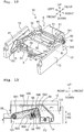
- the movement assembly 30 includes the head pressing member 5, a first movement mechanism 6, the first pivoting member 51, the second pivoting member 52, and a guide rail 53.
- the head pressing member 5 is disposed above the head holding member 4.
- the head pressing member 5 is pivotally supported by the base 2 around a second axis L2 extending in the left-right direction.
- the head pressing member 5 presses the head holding member 4 from above, that is, from a second side in the up-down direction.
- the head pressing member 5 presses the rolling member 45 from above.
- the head pressing member 5 of this embodiment is held by the guide rail 53 to be slidable with respect to the base 2 in the left-right direction.
- the head pressing member 5 of this embodiment faces the thermal head 3 from above.
- a ready-made linear guide can be used as the head pressing member 5 and the guide rail 53.
- the head pressing member 5 is a table attached to the guide rail 53.
- the head pressing member 5 is connected to the coupling member 90.
- the coupling member 90 in this embodiment is removably connected to the head pressing member 5 by using, for example, a screw.
- the coupling member 90 is connected to the head pressing member 5 in a direction corresponding to the head holding direction.
- the direction in which the coupling member 90 is placed relative to the head pressing member 5 is the same as the head holding direction.
- the coupling member 90 includes a guide groove 92 with which the flange 46 of the second engagement member 41 engages.
- the guide groove 92 extending in the front-rear direction guides movement of the head holding member 4 in the front-rear direction.
- the guide groove 92 of this embodiment extends linearly and substantially in the front-rear direction.
- the head pressing member 5 has the contact surface 50 that makes contact with the rolling member 45.
- the contact surface 50 is, for example, a flat surface.
- the contact surface 50 of this embodiment is the lower surface of the head pressing member 5.
- the contact surface 50 faces the head holding member 4.
- a rear end of the head pressing member 5 is connected to a coupling member 95.
- the coupling member 95 includes a bar-like protrusion 103 protruding in the head holding direction.
- the coupling member 95 of this embodiment is connected removably to the head pressing member 5 by using, for example, a screw.
- the coupling member 95 is connected to the head pressing member 5 in a direction corresponding to the head holding direction.
- the first movement mechanism 6 includes a first motor 61, pinions 64 and 65, sector gears 544 and 524.
- the first movement mechanism 6 causes the first pivoting member 51 and the second pivoting member 52 to pivotally move around the second axis L2 extending in the left-right direction.
- the second axis L2 is on the front side of the base 2.
- the second axis L2 of this embodiment is at the substantially same position as the rear end of the attachment part 37 of the thermal head 3 in the front-rear direction.
- the second axis L2 is positioned above a rear end of the thermal head 3.
- the first motor 61 is disposed on the rear side of the base 2.
- the first motor 61 rotates a first output shaft 62 and a second output shaft 63.
- the first output shaft 62 is disposed on the rear side of the base 2 and extends rightward that is the first side in the left-right direction orthogonal to the front-rear direction.
- the second output shaft 63 extends leftward that is the second side in the left-right direction.
- the first motor 61 of this embodiment is a stepper motor.
- the pinion 64 is fixed to a front end of the first output shaft 62.
- the pinion 65 is fixed to a front end of the second output shaft 63.
- the pinions 64 and 65 have the same diameter.
- the rotation axes of the first output shaft 62, the second output shaft 63, the pinon 64, and the pinion 65 are on the same straight line.
- the sector gears 544 and 524 each have an arc-shape of which center is the second axis L2.
- the sector gear 544 is disposed at a rear end of the first pivoting member 51.
- the sector gear 524 is disposed at a rear end of the second pivoting member 52.
- the first pivoting member 51 extends from a position on the rear side of the base 2 to a position on the front side of the base 2.
- the first pivoting member 51 is supported by the base 2 to pivot around the second axis L2 parallel to the left-right direction.
- the first pivoting member 51 is inserted into the hole 18 of the base 2.
- the first pivoting member 51 includes a first part 541, a second part 542, and a third part 543.
- the sector gear 544 disposed at a rear end of the first part 541 is engaged with the first output shaft 62 of the first motor 61.
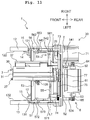
- the first part 541, which is positioned between the first motor 61 and the second motor 71 in the left-right direction, extends frontward beyond the base 2.
- the second part 542 extends rightward, which is the first side in the left-right direction, from a front end of the first part 541.
- the third part 543 extends frontward from a right end of the second part 542.
- the second pivoting member 52 extends from a position on the rear side of the base 2 to a position on the front side of the base 2.
- the second pivoting member 52 is supported by the base 2 to pivot around the second axis L2.
- the second pivoting member 52 is inserted into a hole 88 of the base 2.
- the sector gear 524 disposed at the rear end of the second pivoting member 52 is engaged with the second output shaft 63 of the first motor 61.
- the second pivoting member 52 is disposed on the left side of the first pivoting member 51.
- the guide rail 53 which extends in the left-right direction, is connected to the front end of the first part 541 of the first pivoting member 51 and a front end of the second pivoting member 52.
- the front end of the first part 541 extends frontward beyond front ends of a first pulley 73, a second pulley 74, and a belt 75 which will be described later.
- the second part 542, which extends in the left-right direction, is disposed on the front side of the front ends of the first pulley 73, the second pulley 74, and the belt 75.
- the movement assembly 30 includes a bar-like shaft 55 having the second axis L2.
- the shaft 55 is inserted into the second part 542.
- the second part 542 is provided with a through hole penetrating in the left-right direction, and the shaft 55 is inserted into the through hole.
- the first pillar 12 is disposed on the right side of the first pivoting member 51 to face the first pivoting member 51.
- the first pillar 12 supports a right end of the shaft 55.
- the second pillar 13 is disposed on the left side of the second pivoting member 52 to face the second pivoting member 52.
- the second pillar 13 supports a left end of the shaft 55.
- the shaft 55 is fixed to the first pillar 12 and the second pillar 13 by using screws.
- the first pivoting member 51 and the second pivoting member 52 are supported by the shaft 55 via bearings. Namely, the first pivoting member 51 and the second pivoting member 52 are supported indirectly by the base 2 via the bearings, the shaft 55, the first pillar 12, and the second pillar 13.
- the movement assembly 30 of this embodiment further includes a first connection member 56, a second connection member 57, and urging members 58 and 59.
- the first connection member 56 which is disposed on the left side of the first pillar 12, is pivotally supported by the shaft 55 around the second axis L2 via a bearing.
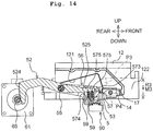
- the first connection member 56 connects a first end 545 that is a front end of the third part 543 of the first pivoting member 51 and a right end of the guide rail 53 such that they are movable relative to each other (specifically, they can rotate relative to each other around the second axis L2).
- the first end 545 is a portion extending from a halfway point between the second axis L2 and the front end of the third part 543 to the front end of the third part 543.
- the first connection member 56 includes an insertion part 561, an arm 562, and a connection part 563.
- the shaft 55 is inserted into the insertion part 561 that is a rear end of the first connection member 56.
- the insertion part 561 is disposed on the right of the third part 543.
- the arm 562 extends frontward from the insertion part 561.
- the insertion part 561 and the arm 562 are placed in the recess 121 of the first pillar 12.
- connection part 563 which extends leftward, is connected to a front end of the arm 562.
- the connection part 563 has a U-shape or horseshoe shape when seen from the left side.
- the connection part 563 has an opening 564 that is open at the rear side.
- the first end 545 of the first pivoting member 51 is inserted into the opening 564.
- the connection part 563 is provided with bar-like members 565 protruding upward from a lower surface.
- the urging member 58 is wound around each bar-like member 565.
- the urging member 58 of this embodiment is a coil spring (e.g., a compression coil spring). A lower end of the urging member 58 is in contact with a lower end of the connection part 563.
- An upper end of the urging member 58 is in contact with the first end 545 of the first pivoting member 51 from below.
- the urging member 58 urges the first end 545 of the first pivoting member 51 inserted into the opening 564 upward.
- a lower surface of the arm 562 is connected to the right end of the guide rail 53.
- a front surface of the first connection member 56 (connection part 563) is connected to the first detection member 16.
- the first sensor 14 is placed in the left surface 122 of the first pillar 12 facing the first connection member 56, at a position facing the first detection member 16 in a state where the guide rail 53 is positioned at a predefined position.
- the predefined position of this embodiment is a position on the lower side of the center of a movable range of the guide rail 53. Namely, the first sensor 14 is disposed on the lower side of a center M2 of a pivoting range R2 of the first detection member 16.
- the pivoting range R2 of the first detection member 16 is defined by a position P1 of the first detection member 16 when the first pivoting member 51 has moved to an upper end of the pivoting range and a position P2 of the first detection member 16 when the first pivoting member 51 has moved to a lower end of the pivoting range.
- the output of the first sensor 14 is used, for example, in processing for adjusting the pressing force to the platen 19 (the ink ribbon 9 and the printing medium 8) from the thermal head 3.
- the pressing force applied from the thermal head 3 to the platen 19 (the ink ribbon 9 and the printing medium 8) depends on lowering amounts of the pivoting members 51 and 52 after the thermal head 3 makes contact with the platen 19 via the ink ribbon 9 and the printing medium 8.
- the lowering amounts of the pivoting members 51 and 52 are controlled by a driving amount of the first motor 61.
- a position of the thermal head 3 in the vicinity of the platen 19 be detected accurately.
- the distance between the first sensor 14 and the first detection member 16 when the thermal head 3 is positioned in the vicinity of the platen 19 in a state where the first sensor 14 is positioned on the lower side of the center M2 of the pivoting range R2 of the first detection member 16 is shorter than the distance between the first sensor 14 and the first detection member 16 when the thermal head 3 is positioned in the vicinity of the platen 19 in a state where the first sensor 14 is positioned on the upper side of the center M2.
- the first sensor 14 is a magnetic sensor and the first detection member 16 is a magnet
- magnetic field intensity detected by the first sensor 14 increases as the distance between the first sensor 14 and the first detection member 16 is shorter. This allows the position of the thermal head 3 in the up-down direction to be detected more accurately.
- the printing apparatus 1 of this embodiment can detect the position of the thermal head 3 in the vicinity of the platen 19 more accurately than a configuration in which the first sensor 14 is positioned on the upper side of the center M2 of the pivoting range R2 of the first detection member 16.
- the second connection member 57 which is disposed on the right side of the second pillar 13, is pivotally supported by the shaft 55 around the second axis L2 via a bearing.
- the second connection member 57 connects a second end 525 that is the front end of the second pivoting member 52 and a left end of the guide rail 53 such that they are movable relative to each other.
- the second connection member 57 includes an insertion part 571, an arm 572, and a connection part 573.
- the shaft 55 is inserted into the insertion part 571 that is a rear end of the second connection member 57.
- the insertion part 571 is disposed on the left side of the second pivoting member 52.
- the arm 572 extends frontward from the insertion part 571.
- the insertion part 571 and the arm 572 are placed in the recess 131 of the second pillar 13.
- connection part 573 which extends rightward, is connected to a front end of the arm 572.
- the connection part 573 has a U-shape or horseshoe shape when seen from the left side.
- the connection part 573 has an opening 574 that is open at the rear side.
- the second end 525 of the second pivoting member 52 is inserted into the opening 574.
- the connection part 573 is provided with bar-like members 575 protruding upward from a lower surface.
- the urging member 59 is wound around each bar-like member 575.
- the urging member 59 of this embodiment is a coil spring (e.g., a compression coil spring). A lower end of the urging member 59 is in contact with a lower end of the connection part 573.
- An upper end of the urging member 59 is in contact with a lower surface of the second end 525 of the second pivoting member 52.
- the urging member 59 urges the second end 525 of the second pivoting member 52 inserted into the opening 574 upward.
- a lower surface of the arm 572 is connected to the left end of the guide rail 53.
- a front surface of the second connection member 57 (connection part 573) is connected to the second detection member 17.
- the second sensor 15 is disposed in a right surface of the second pillar 13 facing the second connection member 57, at a position facing the second detection member 17 in the state where the guide rail 53 is positioned at the predefined position.
- the second sensor 15 is positioned on the lower side of a center M3 of a pivoting range R3 of the second detection member 17.
- the pivoting range R3 of the second detection member 17 is defined by a position P3 of the second detection member 17 when the second pivoting member 52 has moved to an upper end of the pivoting range and a position P4 of the second detection member 17 when the second pivoting member 52 has moved to a lower end of the pivoting range.
- connection part 563 and the connection part 573 of this embodiment configure a member 68 formed as one piece.
- the member 68 extends in the left-right direction.
- a right end of the member 68 is the connection part 563 and a left end of the member 68 is the connection part 573.
- the guide rail 53 is fixed to a lower surface of the member 68.
- the lower surface of the member 68 is a surface facing the head holding member 4.
- the output of the second sensor 15 is used in processing for adjusting pressing force to the platen 19 (the ink ribbon 9 and the printing medium 8) from the thermal head 3.
- the position of the second sensor 15 in the up-down direction is the same as the position of the first sensor 14 in the up-down direction. Since the printing apparatus 1 of this embodiment includes the first sensor 14 and the second sensor 15, output values of the first sensor 14 and the second sensor 15 can be used in processing for detecting an inclination of the guide rail 53 (the member 68) in the left-right direction.
- the movement assembly 30 further includes guide rails 82 and 83, sliding members 84 and 85, a plate member 86, and an urging member 100.
- the guide rails 82 and 83 which extend in the up-down direction, are fixed to a sliding member 77 described later.
- the sliding members 84 and 85 are held by the guide rails 82 and 83 to be slidable with respect to the base 2 in the up-down direction.
- the sliding members 84 and 85 are connected to the head holding member 4.
- the guide rails 82 and 83 are arranged with an interval in the front-rear direction.
- the movement assembly 30 of this embodiment includes two guide rails (i.e., the guide rails 82 and 83).
- the guide rails 82 and 83 of this embodiment are fixed to the sliding member 77 via coupling members 78 and 79.
- the coupling member 78 which has a square pole shape, is fixed to the front surface of the sliding member 77.
- the coupling member 79 which has a plate shape, is fixed to an attachment surface of the coupling member 78.
- the attachment surface of the coupling member 78 is one of the left and right surfaces of the coupling member 78 that is positioned in a direction opposite to the head holding direction.
- the coupling member 79 extends frontward beyond the coupling member 78 and includes rail placement grooves 80 and 81 extending in the up-down direction.
- the rail placement grooves 80 and 81 are grooves in which the guide rails 82 and 83 extending in the up-down direction are placed, respectively.
- the rail placement grooves 80 and 81 are arranged in the front-rear direction.
- the rail placement grooves 80 and 81 are provided in left and right surfaces of the coupling member 79, respectively.
- the guide rails 82 and 83 are attached to a surface of the coupling member 79 on a side facing the head holding member 4 by use of screws.
- the sliding members 84 and 85 are held by the guide rails 82 and 83.
- the sliding member 84 and 85 respectively face the guide rails 82 and 83 in the left-right direction.
- the sliding member 84 disposed on the front side faces the fourth magnetic member 43 in the left-right direction.
- the plate member 86 is fixed to the sliding member 84 at a position between the sliding member 84 and the head holding member 4.
- the plate member 86 goes around the front side of the coupling member 79, turns or curves to the opposite side of the head holding direction, and extends rearward on the opposite side of the head holding direction in a state of being separated from the coupling member 79.
- the plate member 86 is provided with a protrusion 105 protruding in the direction opposite to the head holding direction.
- An end 101 of the urging member 100 of this embodiment is connected to the protrusion 103 of the head pressing member 5.
- the other end of the urging member 100 is connected to the protrusion 105 of the plate member 86 connected to the sliding member 77.
- the guide rails 82, 83 and the sliding members 84, 85 are positioned between the rolling member 45 and the guide rail 76 in the front-rear direction.
- the head holding member 4 is connected to the sliding members 84 and 85 by use of screws, and it is disposed on the front side of the sliding member 77 without connected directly to the sliding member 77. Namely, the head holding member 4 is connected indirectly to the sliding member 77 via the sliding members 84 and 85, the guide rails 82 and 83, and the coupling members 78 and 79.
- the user When changing the head holding direction, the user removes, together with the second engagement member 41, the coupling member 79, the guide rails 82 and 83, the sliding members 84 and 85, and the plate member 86 from the coupling member 78 and the head holding member 4. Then, the user places them in positions depending on the head holding direction. The user removes the guide shaft 27 from the sliding member 77, and then places the guide shaft 27 in a position depending on the head holding direction. The guide shaft 27 is placed on the opposite side of the head holding direction relative to the head holding member 4. The user removes the coupling member 95 from the head pressing member 5, and then places it in a position on the opposite side of the head holding direction relative to the head pressing member 5.
- the second movement mechanism 7 includes the second motor 71. Driving the second motor 71 moves the head holding member 4 in the left-right direction.
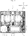
- the second motor 71 includes a third output shaft 72 extending frontward that is the first side in the front-rear direction. As depicted in Fig. 4 , the second motor 71 is disposed on the right side of the first motor 61 and on the rear side of the base 2. At least a part of the second motor 71 overlaps with the first motor 61 in the up-down direction perpendicular to the front-rear direction and the left-right direction.
- the second motor 71 of this embodiment is a stepper motor.
- the first motor 61 and the second motor 71 in this embodiment have substantially the same size in the up-down direction, and the length of the first motor 61 in the up-down direction is the same as the length of the second motor 71 in the up-down direction.
- the second movement mechanism 7 includes the first pulley 73, the second pulley 74, and the belt 75.
- the first pulley 73 is connected to the third output shaft 72.
- the second pulley 74 is disposed on the left side of the first pulley 73.
- the belt 75 which is connected to the head holding member 4, is stretched between the first pulley 73 and the second pulley 74.
- the first pulley 73 and the second pulley 74 have substantially the same diameter.
- the center of the first pulley 73 is positioned on the left of the left surface 122 of the first pillar 12.
- the center of the second pulley 74 is positioned on the right of the right surface 132 of the second pillar 13.
- the belt 75 extends in the left-right direction.
- the guide rail 76 which extends in the left-right direction, is disposed on the front side of the base 2 and on the rear side of the second axis L2.
- the sliding member 77 is connected to a rear end of the head holding member 4.
- the sliding member 77 is held by the guide rail 76 to be slidable with respect to the base 2 in the left-right direction.
- the guide rail 76 faces the sliding member 77 in the front-rear direction.
- a ready-made linear guide can be used as the sliding member 77 and the guide rail 76. In that case, the sliding member 77 is a table attached to the guide rail 76.
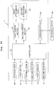
- the printing apparatus 1 includes the controller 67, a storage part 66, the thermal head 3, the first motor 61, the second motor 71, the first sensor 14, the second sensor 15, a first ribbon motor 23, a second ribbon motor 24, and the communication interface (communication I/F) 60.
- the controller 67 includes a hardware processor (e.g., CPU) controlling the printing apparatus 1 and various driving circuits each operating in response to an instruction of the hardware processor.
- the various driving circuits include, for example, circuits supplying signals (e.g., driving current) to the first motor 61, the second motor 71, the first ribbon motor 23, and the second ribbon motor 24, a circuit supplying a signal (e.g., a driving current) to the thermal head 3, and a circuit driving the sensors 14, 15 and performing A/D conversion of an output signal received.
- the controller 67 is electrically connected to the storage part 66, the thermal head 3, the first motor 61, the second motor 71, the first sensor 14, the second sensor 15, the first ribbon motor 23, the second ribbon motor 24, and the communication I/D 60.
- the storage part 66 includes various storage mediums such as ROM, RAM, and a flash memory.
- the storage part 66 stores a printing program including an instruction that causes the controller 67 to perform printing control processing described later.
- the storage part 66 further stores various setting values to drive the printing apparatus 1.
- Each of the heating elements 31 of the thermal head 3 produces heat in response to a signal output from the controller 67.
- the first ribbon motor 23 rotates the first attachment part 21 in response to a pulse signal output from the controller 67.
- the second ribbon motor 24 rotates the second attachment part 22 in response to a pulse signal output from the controller 67.
- the first motor 61 rotates in response to a pulse signal output from the controller 67 to move the thermal head 3 between the printing position and the standby position and the retreat position (not depicted).
- the second motor 71 rotates in response to a pulse signal output from the controller 67 to move the thermal head 3 in the left-right direction.
- Each of the motors 23, 24, 61, and 71 is a stepper motor.
- the controller 67 controls each motor by controlling, for example, the number of steps to be transmitted to the motor.
- the first sensor 14 outputs, to the controller 67, a signal corresponding to a position of the first detection member 16 in the up-down direction.
- the second sensor 15 outputs, to the controller 67, a signal corresponding to a position of the second detection member 17 in the up-down direction.
- Each of the first sensor 14 and the second sensor 15 is, for example, a non-contact magnetic sensor (e.g., a Hall element) that can output a signal depending on the change in magnetic flux density.
- Each of the first detection member 16 and the second detection member 17 is a permanent magnet.
- the storage part 66 stores a printing program including an instruction to perform print processing.
- the controller 67 performs the print processing by developing the printing program on the RAM of the storage part 66.
- printing is performed, for example, on condition that the conveyance of the printing medium 8 by use of the printing medium conveyance apparatus is performed periodically during a conveyance period.
- An external device 99 inputs a printing instruction to the printing apparatus 1 at timing at which the conveyance period ends.
- the controller 67 starts the printing on the printing medium 8. Specifically, the controller 67 controls the first motor 61 to move the thermal head 3 from the standby position to the printing position.
- the controller 67 detects that the thermal head 3 has reached a predefined position in the up-down direction based on the signals output from the first sensor 14 and the second sensor 15.
- the pivoting members 51 and 52 in this embodiment are configured to be asymmetric in the left-right direction, and the position of the thermal head 3 in the left-right direction depends on the printing position. Thus, the position of the thermal head 3 in the left-right direction may not be the center in the left-right direction. In that configuration, when the thermal head 3 is pressed by the head pressing member 5, the guide rail 53 is liable to inline in the left-right direction.
- the printing apparatus 1 may change the sensor to be used depending on the position of the thermal head 3 in the left-right direction.
- the printing apparatus 1 may detect the position of the thermal head 3 in the up-down direction based on the signal output from the first sensor 14 or the second sensor 15 positioned closer to the heating elements 31 of the thermal head 3. Accordingly, the printing apparatus 1 can accurately detect the position of the thermal head 3 in the up-down direction as compared to a case using a signal output from the same sensor irrespective of the position of the thermal head 3 in the left-right direction.
- the controller 67 controls the first motor 61 based on the signals output from the first sensor 14 and the second sensor 15 to adjust the pressing force applied from the thermal head 3 to the ink ribbon 9 and the printing medium 8.
- the head pressing member 5 presses the rolling member 45 of the head holding member 4 downward along with driving of the first motor 61.
- the pressing force directed downward and received by the rolling member 45 is transmitted to the thermal head 3 via the curved surface 377.
- the pressing force of the head pressing member 5 allows the thermal head 3 to pivot around the first axis L1 against the static frictional force between the first magnetic member 34 and the second magnetic member 42 and the static frictional force between the third magnetic member 35 and the fourth magnetic member 43, as depicted in Fig. 7B .
- the thermal head 3 presses the ink ribbon 9 and the printing medium 8 downward in the front-rear direction with substantially uniform force.
- the controller 67 controls the second motor 71 so that the thermal head 3 moves in the left-right direction at a predefined speed while making contact with the ink ribbon 9. At the same time, the controller 67 heats the heating elements 31 of the thermal head 3 based on printing data to transfer the ink of the ink ribbon 9 to a printing surface (an upper surface) of the printing medium 8. Upon completion of the printing, the controller 67 stops the heating of the thermal head 3 and controls the first motor 61 to move the thermal head 3 from the printing position to the standby position.
- the thermal head 3 When the thermal head 3 no longer receives the pressing force, which is applied from the head pressing member 5 to be directed downward, the thermal head 3 pivots around the first axis L1 due to the magnetic force between the first magnetic member 34 and the second magnetic member 42 and the magnetic force between the third magnetic member 35 and the fourth magnetic member 43.
- the position of the thermal head 3 relative to the head holding member 4 returns to the reference position where the center position C1 of the first magnetic member 34 coincides with the center position C2 of the second magnetic member 42 and the center position C3 of the third magnetic member 35 coincides with the center position C4 of the fourth magnetic member 43, as depicted in Fig. 7A .
- the printing apparatus 1 controls the first ribbon motor 23 and the second ribbon motor 24 to convey the ink ribbon 9 and controls the second motor 71 to move the thermal head 3 in the left-right direction, as needed.
- the printing apparatus 1 may perform the print processing during the conveyance of the printing medium 8 without moving the thermal head 3 in the left-right direction.
- the platen 19 is preferably a roller-shaped platen.
- the external device 99 inputs a printing instruction to the printing apparatus 1 at predefined timing.
- the controller 67 starts printing on the printing medium 8 when receiving the printing instruction.
- the controller 67 controls the first motor 61 to move the thermal head 3 from the standby position to the printing position.
- the controller 67 detects that the thermal head 3 has reached the predefined position in the up-down direction based on the signals output from the first sensor 14 and the second sensor 15.
- the controller 67 adjusts the pressing force to be applied from the thermal head 3 to the ink ribbon 9 and the printing medium 8 by controlling the first motor 61 based on the signals output from the first sensor 14 and the second sensor 15.
- the controller 67 controls the first ribbon motor 23 and the second ribbon motor 24 to convey the ink ribbon 9 making contact with the thermal head 3 in a direction that is the same as the conveyance direction of the printing medium 8. In that situation, the conveyance speed of the ink ribbon 9 is the same as the conveyance speed of the printing medium 8 or slightly slower than the conveyance speed of the printing medium 8. The conveyance speed of the printing medium 8 may be obtained, for example, from the external device 99 or may be detected by using a sensor or the like.
- the controller 67 heats the heating elements 31 of the thermal head 3 based on printing data and transfers the ink of the ink ribbon 9 to the printing surface (the upper surface) of the printing medium 8.
- the controller 67 stops the heating of the thermal head 3 and the conveyance of the ink ribbon 9, and then controls the first motor 61 to move the thermal head 3 from the printing position to the standby position.
- the base 2 is an exemplary base of the present invention
- the thermal head 3 is an exemplary thermal head of the present invention
- the first output shaft 62 is an exemplary first output shaft of the present invention
- the second output shaft 63 is an exemplary second output shaft of the present invention
- the first motor 61 is an exemplary first motor of the present invention
- the third output shaft 72 is an exemplary third output shaft of the present invention
- the second motor 71 is an exemplary second motor of the present invention
- the head holding member 4 is an exemplary head holding member of the present invention
- the first pivoting member 51 is an exemplary first pivoting member of the present invention
- the first part 541 is an exemplary first part of the present invention
- the second part 542 is an exemplary second part of the present invention
- the third part 543 is an exemplary third part of the present invention
- the second pivoting member 52 is an exemplary second pivoting member of the present invention
- the guide rail 53 is an exemplary guide rail of the present invention
- the head pressing member 5 is an exemplary
- the first pulley 73 is an exemplary first pulley of the present invention
- the second pulley 74 is an exemplary second pulley of the present invention
- the belt 75 is an exemplary belt of the present invention
- the shaft 55 is an exemplary shaft of the present invention.
- the first pillar 12 is an exemplary first pillar of the present invention
- the second pillar 13 is an exemplary second pillar of the present invention
- the first connection member 56 is an exemplary connection member of the present invention
- the first urging member 58 is an exemplary first urging member of the present invention
- the second connection member 57 is an exemplary second connection member of the present invention
- the second urging member 59 is an exemplary second urging member of the present invention.
- the first detection member 16 is an exemplary first detection target member of the present invention
- the first sensor 14 is an exemplary first sensor of the present invention
- the second detection member 17 is an exemplary second detection target member of the present invention
- the second sensor 15 is an exemplary second sensor of the present invention.
- the first pivoting member 51 includes the first part 541, the second part 542, and the third part 543.
- the first pivoting member 51 does not interfere with the second motor 71 even when a movable range of the thermal head 3 in the left-right direction is longer than conventional apparatuses.
- the printing apparatus 1 can prevent the increase in size of the configuration displacing the thermal head 3 as compared to conventional printing apparatuses in which the second motor 71 is disposed on an upper or lower side of the belt 75. Namely, the printing apparatus 1 can prevent the interference of the second motor 71 with the first pivoting member 51.
- the second motor 71 has the third output shaft 72 extending frontward.
- the second movement mechanism 7 includes the first pulley 73 connected to the third output shaft 72, the second pulley 74 disposed on the left side of the first pulley 73 to be separated therefrom, and the belt 75 connected to the head holding member 4 and stretched between the first pulley 73 and the second pulley 74.
- a relatively simple configuration configured by the first pulley 73, the second pulley 74, and the belt 75 moves the thermal head 3 held by the head holding member 4 in the left-right direction.
- the front end of the first part 541 of the first pivoting member 51 extends frontward beyond the first pulley 73, the second pulley 74, and the belt 75.
- the second part 542, which extends in the left-right direction, is disposed on the front side of the first pulley 73, the second pulley 74, and the belt 75.
- the guide rail 53 can be lengthened in the left-right direction while avoiding the interference of the guide rail 53 with the second movement mechanism 7.
- the printing apparatus 1 includes the shaft 55 having the second axis L2.
- the shaft 55 is inserted into the second part 542.
- the first pivoting member 51 and the second pivoting member 52 of the printing apparatus 1 pivot around the shaft 55 inserted into the second part 542.
- the printing apparatus 1 can reduce a space required for pivoting of the first pivoting member 51 and the second pivoting member 52 as compared to a case in which the shaft 55 is not inserted into the second part 542.
- the printing apparatus 1 includes the first pillar 12 and the second pillar 13.
- the first pillar 12 extends frontward from the base 2 beyond the shaft 55, faces the first pivoting member 51 from the right side, and supports the shaft 55.
- the second pillar 13 extends frontward from the base 2 beyond the shaft 55, faces the second pivoting member 52 from the left side, and supports the shaft 55.
- the shaft 55 is supported by the first pillar 12 and the second pillar 13 on its left and right sides, preventing the shaft 55 from inclining to the left-right direction which may otherwise be caused by variation in load applied to the first pivoting member 51 and the second pivoting member 52.
- the printing apparatus 1 includes the first connection member 56, the first urging member 58, the second connection member 57, and the second urging member 59.
- the first connection member 56 is disposed on the left side of the first pillar 12.
- the first connection member 56 is supported to be pivotally movable around the shaft 55.
- the first connection member 56 connects the first end 545 of the first pivoting member 51 and the right end of the guide rail 53 such that they are movable relative to each other.
- the first urging member 58 which is provided in the first connection member 56, is in contact with a lower portion of the first end 545.
- the second connection member 57 is disposed on the right side of the second pillar 13.
- the second connection member 57 is supported to be pivotally movable around the shaft 55.
- the second connection member 57 connects the second end 525 and the left end of the guide rail 53 such that they are movable relative to each other.
- the second urging member 59 which is provided in the second connection member 57, is in contact with a lower portion of the second end 525.
- the first connection member 56 and the second connection member 57 allow the first pivoting member 51 and the second pivoting member 52 to be connected to the guide rail 53 such that the guide rail 53 is movable relative to the first pivoting member 51 and the second pivoting member 52.
- the pressing force to be applied to the ink ribbon 9 via the head pressing member 5 and the thermal head 3 is adjusted by the compression amounts of the first urging member 58 and the second urging member 59.
- the printing apparatus 1 includes the first detection member 16 and the first sensor 14.
- the first detection member 16 is provided in the first connection member 56.
- the first sensor 14 is provided in the surface facing the first connection member 56 of the first pillar 12 at the position facing the first detection member 16 in the state where the guide rail 53 is disposed at the predefined position.
- the first sensor 14 outputs the signal corresponding to the position of the first detection member 16 in the up-down direction.
- the printing apparatus 1 detects the position of the thermal head 3 in the up-down direction based on the signal output from the first sensor 14.
- the thermal head 3 approaches or makes contact with the platen 19 disposed on the lower side of the thermal head 3 in a state where the first pivoting member 51 is disposed at the lower end in its pivoting range.
- the first sensor 14 is disposed on the lower side of the center M2 of the pivoting range R2 of the first detection member 16.
- the distance between the first sensor 14 and the first detection member 16 when the thermal head 3 is positioned in the vicinity of the platen 19 in the state where the first sensor 14 is disposed on the lower side of the center M2 of the pivoting range R2 of the first detection member 16 is shorter than the distance between the first sensor 14 and the first detection member 16 when the thermal head 3 is positioned in the vicinity of the platen 19 in the state where the first sensor 14 is disposed on the upper side of the center M2.
- the first sensor 14 is a magnetic sensor and the first detection member 16 is a magnet
- magnetic field intensity detected by the first sensor 14 increases as the distance between the first sensor 14 and the first detection member 16 is shorter. This allows the position of the thermal head 3 in the up-down direction to be detected more accurately.
- the printing apparatus 1 includes the second detection member 17 and the second sensor 15.
- the second detection member 17 is provided in the second connection member 57.
- the second sensor 15 is provided in the surface facing the second connection member 57 of the second pillar 13 at the position facing the second detection member 17 in the state where the guide rail 53 is disposed at the predefined position.
- the second sensor 15 outputs the signal corresponding to the position of the second detection member 17 in the up-down direction.
- the printing apparatus 1 detects the position of the thermal head 3 in the up-down direction based on the signal output from the second sensor 15.
- the printing apparatus 1 of this embodiment includes the first sensor 14 and the second sensor 15, output values from the first sensor 14 and the second sensor 15 can be used, for example, in processing for detecting the inclination of the guide rail 53 (the member 68) in the left-right direction.
- the printing apparatus 1 may calculate the position of the thermal head 3 in the up-down direction by using the inclination of the guide rail 53 in the left-right direction. This enhances accuracy of the position of the thermal head 3 in the up-down direction, which is calculated based on the output values from the first sensor 14 and the second sensor 15.
- the printing apparatus of the present invention is not limited to the above embodiment, and may be appropriately changed within a range without changing the gist or essential characteristics of the present invention.
- the following modifications may be added to the printing apparatus of the present invention as appropriate.
- the configuration of the printing apparatus 1 may be changed appropriately.
- the first direction, the second direction, and the third direction of the printing apparatus 1 may be changed appropriately.
- the first direction, the second direction, and the third direction may intersect with each other, instead of being orthogonal or perpendicular to each other.
- the printing apparatus 1 may include the printing medium conveyance unit conveying the printing medium 8.
- the configuration of the printing medium 8 and the ink ribbon 9 may be changed appropriately.
- the driving sources moving the respective members may be changed appropriately.
- the conveyance path of the ink ribbon 9 of the printing apparatus 1 may be changed appropriately.
- the configuration of the first pivoting member 51 and the second pivoting member 52 may be changed appropriately.
- the printing apparatus 1 may not include a part or all of the components of the ribbon conveyance mechanism 20.
- the printing apparatus 1 may include the platen 19.
- the platen 19 may have a plate shape or a roller shape.
- the base 2 may not be a member in a flat plate shape.
- the base 2 may be a member of which surface has a concavity and a convexity or a member of which surface is curved.
- the base 2 may have a box shape.
- the configuration of the movement assembly 30 and the second movement mechanism 7 may be changed appropriately.
- the configuration of the thermal head 3 and the head holding member 4 may be changed appropriately.
- the thermal head 3 and the head holding member 4 may not be held by the magnetic force between the magnetic members.
- the printing apparatus 1 may not be configured such that the head holding direction is changeable.
- the first motor may include motors provided in the first pivoting member 51 and the second pivoting member 52, respectively.
- the third output shaft 72 may not extend frontward.
- the second movement mechanism 7 may have a configuration that is different from the configuration formed from the first pulley 73, the second pulley 74, and the belt 75.
- the arrangement of the second movement mechanism 7 may be changed appropriately.
- the position of the front end of the first part 541 and the second part 542 in the front-rear direction may be same as that of the first pulley 73, the second pulley 74, and the belt 75 or may be on the rear side of that of the first pulley 73, the second pulley 74, and the belt 75.
- the shaft 55 may not be inserted into the first pivoting member 51 (the second part 542) and the second pivoting member 52.
- the printing apparatus 1 may not include the first pillar 12 and the second pillar 13.
- the configuration of the first pillar 12 and the second pillar 13 may be changed appropriately.
- the shaft 55 may be pivotally supported by the first pillar 12 and the second pillar 13.
- the shaft 55 may be directly supported by the base 2 without using the first pillar 12 and the second pillar 13.
- the printing apparatus 1 may not include a part or all of the first connection member 56, the first urging member 58, the second connection member 57, and the second urging member 59, and the configuration, arrangement, and the like thereof may be changed appropriately.
- first connection member 56 and the second connection member 57 may be positioned inside the pivoting members 51 and 52 (the head holding member 4 side in the left-right direction) such that the connection members, the pivoting members, and the pillars are arranged in that order from the side closer to the head holding member 4 in the left-right direction.
- the printing apparatus 1 may not include a part or all of the first detection member 16, the first sensor 14, the second detection member 17, and the second sensor 15, and the configuration, arrangement, and the like thereof may be changed appropriately.
- the first sensor 14 and the second sensor 15 may be sensors of different types or sensors of the same type.
- at least one of the first sensor 14 and the second sensor 15 may be an optical sensor or an ultrasonic sensor.
- the first sensor 14 and the second sensor 15 may be placed at the same position in the up-down direction or placed at different positions in the up-down direction.
- the printing apparatus 1 may have a configuration of a modified embodiment depicted in Fig. 19 instead of the configuration depicted in Fig. 17 .
- Fig. 19 the components or parts which are basically the same as those of the embodiment depicted in Fig. 17 are designated by the same reference numerals.
- a thermal head 3 of the modified embodiment depicted in Fig. 19 has a length in the front-rear direction (e.g., about 5 cm) that is shorter than the length of the thermal head 3 in the front-rear direction (e.g., about 13 cm) of the embodiment depicted in Fig. 17 .
- Fig. 19 the components or parts which are basically the same as those of the embodiment depicted in Fig. 17 are designated by the same reference numerals.
- a thermal head 3 of the modified embodiment depicted in Fig. 19 has a length in the front-rear direction (e.g., about 5 cm) that is shorter than the length of the thermal head 3 in the front-rear direction (e.g.
- a coupling member 190, a guide rail 182, and a sliding member 184 are configured differently from those of the embodiment depicted in Fig. 17 . Explanation of the components that are configured similarly to those of the embodiment depicted in Fig. 17 will be omitted, and the coupling member 190, the guide rail 182, and the sliding member 184 will be explained below.
- the coupling member 190 has a plate shape extending along a surface that includes the front-rear direction and the up-down direction. An upper front end of the coupling member 190 is fixed to the head pressing member 5 with a screw.
- the coupling member 190 has a long hole 191.
- a longitudinal direction of the long hole 191 is the front-rear direction, and a lateral direction of the long hole 191 is the up-down direction.
- the long hole 191 extends linearly in the longitudinal direction.
- the long hole 191 penetrates in the left-right direction.
- the second engagement member 41 having the shaft shape is inserted into the long hole 191 with the flange 46 positioned at the second end of the second engagement member 41 being positioned on the right side.
- the direction in which the flange 46 is positioned relative to the coupling member 190 coincides with the direction in which the coupling member 190 is positioned relative to the head pressing member 5.
- the diameter of the flange 46 is longer than the length of the long hole 191 in the lateral direction.
- the guide rail 182 extending in the up-down direction is connected to the front surface of the sliding member 77.
- the sliding member 184 is held by the guide rail 182 to be slidable with respect to the base 2 in the up-down direction.
- the sliding member 184 is connected to the rear end of the head holding member 4.
- the guide rail 182 faces the sliding member 184 in the front-rear direction.
- the single guide rail 182 is connected to the sliding member 77.
- the single sliding member 184 is connected to the head holding member 4. In the modified embodiment, when changing the head holding direction, the user does not need to change the placement positions of the guide rail 182 and the sliding member 184 together with the second engagement member 41.
Landscapes
- Electronic Switches (AREA)
- Common Mechanisms (AREA)
Abstract
Description
- The present invention relates to a printing apparatus.
- There is known a thermal-transfer printing apparatus using a thermal head in which the thermal head is slidable in two directions (an up-down direction and a left-right direction) intersecting with a front-rear direction that is an arrangement direction of heating elements of the thermal head (for example, see Patent Literature 1). As a configuration moving the thermal head in the up-down direction, the printing apparatus described in
Patent Literature 1 includes a pair of end assemblies extending in the front-rear direction, a rail bar extending in the left-right direction, a pair of gear pieces, a pivot bar extending in the left-right direction, and a fork assembly. The gear pieces engage with gears of a first motor, and driving of the first motor causes the gear pieces to pivotally move around the pivot bar. The fork assembly to which the pivot bar is attached also pivots around the pivot bar by being pressed from the above by use of the rail bar. A front end of the fork assembly is provided with a bearing. Power of the motor is transmitted to a carriage holding the thermal head via the bearing to move the carriage in the up-down direction. The printing apparatus includes a driving belt and a bearing surface as a configuration moving the thermal head in the left-right direction. The driving belt, which is stretched between a first pulley and a second pulley, extends in the left-right direction. The driving belt is connected to the carriage. The carriage moves in the left-right direction depending on the movement of the driving belt. - Patent Literature 1: United States Patent No.
8,937,634 specification - Conventional printing apparatuses are desired to downsize a configuration displacing a thermal head and to increase a printable range by extending a displaceable range of the thermal head. In the conventional printing apparatuses, a fork assembly and the thermal head move, in a left-right direction, along a rail bar having a bearing surface. A movable range of the thermal head in the left-right direction is defined by a length of the rail bar in the left-right direction. When the movable range of the thermal head in the left-right direction is extended, the length of the rail bar in the left-right direction is required to be extended. In order to extend the length of the rail bar in the left-right direction, an interval between end assemblies that are respectively attached to the gear pieces is required to be widened. Widening the interval between the end assemblies, however, may cause interference of the end assemblies with other components. For example, the conventional printing apparatuses need to include a second motor rotating a first pulley or a second pulley. Disposing the second motor in the vicinity of a buck surface of the first pulley or the second pulley to downsize the printing apparatus may downsize a power transmission mechanism from the second motor to the first pulley or the second pulley. If the second motor is disposed in the vicinity of the back surface of the first pulley or the second pulley, and if the interval between the end assemblies is increased, the second motor may interfere with the end assemblies. For example, when the interference of the second motor with the end assemblies is prevented by changing the arrangement of the second motor, specifically, by disposing the second motor at a position separated from the driving belt in the up-down direction, the printing apparatus increases in size.
- An object of the present invention is to provide a printing apparatus that can increase a printable range while preventing interference of a second motor with end assemblies and preventing a configuration displacing a thermal head from increasing in size, as compared to conventional printing apparatuses in which a second motor is disposed on an upper or lower side of a driving belt.
- A printing apparatus according to a first aspect of the present invention includes: a base; a thermal head in which heating elements are arranged in a first direction; a first motor disposed on a second side in the first direction from the base, the second side being opposite to a first side in the first direction from the base, and configured to rotate a first output shaft extending to a first side in a second direction and a second output shaft extending to a second side in the second direction, the second direction intersecting with the first direction; a second motor disposed on the second side in the first direction from the base and on the first side in the second direction from the first motor to be separated therefrom, wherein at least a part of an extended area of the second motor which extends in a third direction intersecting with both the first direction and the second direction overlaps with an extended area of the first motor; a head holding member disposed on the first side in the first direction from the base, the head holding member being slidable with respect to the base in the third direction, and the head holding member holding the thermal head; a first pivoting member extending from the second side in the first direction from the base to the first side in the first direction from the base, the first pivoting member being supported by the base pivotally around an axis extending in the second direction; the first pivoting member including: a first part having an end on the second side in the first direction, the first part extending to the first side in the first direction from the base at a position between the first motor and the second motor in the second direction, the end of the first part on the second side in the first direction being engaged with the first output shaft of the first motor; a second part extending from an end of the first part on the first side in the first direction to the first side in the second direction; and a third part extending from an end of the second part on the first side in the second direction to the first side in the first direction; a second pivoting member extending from the second side in the first direction from the base to the first side in the first direction from the base, the second pivoting member being supported by the base pivotally around the axis, the second pivoting member having an end on the second side in the first direction, the second pivoting member being disposed on the second side in the second direction from the first pivoting member to be separated therefrom, and the end of the second pivoting member on the second side in the first direction being engaged with the second output shaft of the first motor; a guide rail extending in the second direction and connected to a first end of the first pivoting member on the first side in the first direction and to a second end of the second pivoting member on the first side in the first direction; a head pressing member being in contact with the guide rail slidable in the second direction, the head pressing member facing the thermal head from a first side in the third direction; and a movement mechanism configured to move the head holding member in the second direction through driving of the second motor.
- A printing apparatus according to a second aspect of the present invention includes: a base; a thermal head in which heating elements are arranged in a front-rear direction; a first motor disposed on a rear side of the base, the first motor being configured to rotate a first output shaft extending to a first side in a left-right direction and a second output shaft extending to a second side in the left-right direction, the left-right direction intersecting with the front-rear direction; a second motor disposed on the rear side of the base and on the first side in the left-right direction from the first motor to be separated therefrom, wherein at least a part of an extended area of the second motor which extends in an up-down direction intersecting with the front-rear direction and the left-right direction overlaps with an extended area of the first motor; a head holding member disposed on the front side of the base, the head holding member being slidable with respect to the base in the up-down direction, and the head holding member holding the thermal head; a first pivoting member extending from the rear side of the base to the front side of the base, the first pivoting member being supported by the base pivotally around an axis extending in the left-right direction, the first pivoting member including: a first part having a rear end, the first part extending to the front side of the base at a position between the first motor and the second motor in the left-right direction, the rear end of the first part being engaged with the first output shaft of the first motor; a second part extending from a front end of the first part to the first side in the left-right direction; and a third part extending from an end of the second part on the first side in the left-right direction to the front side; a second pivoting member extending from the rear side of the base to the front side of the base, the second pivoting member being supported by the base pivotally around the axis, the second pivoting member having a rear end, the second pivoting member being disposed on the second side in the left-right direction from the first pivoting member to be separated therefrom, the rear end of the second pivoting member being engaged with the second output shaft of the first motor; a guide rail extending in the left-right direction, the guide rail being connected to both a front end of the first pivoting member and to a front end of the second pivoting member; a head pressing member being in contact with the guide rail to be slidable in the left-right direction, the head pressing member facing the thermal head from an upper side; and a movement mechanism configured to move the head holding member in the left-right direction through driving of the second motor.
- In the printing apparatuses according to the first aspect and the second aspect of the present invention, the first pivoting member includes the first part, the second part, and the third part. This prevents the first pivoting member from interfering with the second motor even when the movable range of the thermal head in the second direction is made to be longer than conventional apparatuses for the purpose of increasing a printable range. Thus, the printing apparatuses according to the first aspect and the second aspect of the present invention prevent a configuration displacing the thermal head from increasing in size as compared to conventional printing apparatuses in which a second motor is disposed on an upper or lower side of a driving belt. The printing apparatuses according to the first aspect and the second aspect of the present invention prevent the interference of the second motor with the first pivoting member.
-
-
Fig. 1 is a perspective view of aprinting apparatus 1. -
Fig. 2 is a perspective view of theprinting apparatus 1 from which aribbon conveyance mechanism 20 is removed. -
Fig. 3 is a front view of theprinting apparatus 1 from which theribbon conveyance mechanism 20 is removed. -
Fig. 4 is a back view of theprinting apparatus 1 from which acover 11 is removed. -
Fig. 5 is a perspective view depicting a state in which athermal head 3 is attached to ahead holding member 4 to have a first posture. -
Fig. 6 is a perspective view of thethermal head 3 that is held by thehead holding member 4 to have the first posture. -
Figs. 7A and 7B each depict a state in which an extending direction of thehead holding member 4 is inclined to aplaten 19 in a front-rear direction,Fig. 7A schematically depicting thehead holding member 4 and thethermal head 3 that is held by thehead holding member 4 to have the first posture and is positioned at a standby position,Fig. 7B schematically depicting thehead holding member 4 and thethermal head 3 that is held by thehead holding member 4 to have the first posture and is positioned at a printing position. -
Fig. 8A is a cross-sectional view taken along an arrow VIIIA-VIIIA inFig. 6 ,Fig. 8B is a cross-sectional view taken along an arrow VIIIB-VIIIB inFig. 9 , andFig. 8C is a schematic plan view of thethermal head 3 that is held by thehead holding member 4 to have the first posture. -
Fig. 9 is a perspective view of thethermal head 3 that is held by thehead holding member 4 to have a second posture. -
Fig. 10 is a cross-sectional view taken along an arrow X-X inFig. 9 . -
Fig. 11 is a bottom view of theprinting apparatus 1 from which thecover 11 is removed. -
Fig. 12 is a perspective view of amovement assembly 30. -
Fig. 13 is a cross-sectional view taken along an arrow XIII-XIII inFig. 3 . -
Fig. 14 is a cross-sectional view taken along an arrow XIV-XIV inFig. 3 . -
Fig. 15 is a front view of thethermal head 3 that is held by thehead holding member 4 to have the second posture. -
Fig. 16 is a perspective view of thethermal head 3 that is held by thehead holding member 4 to have the second posture. -
Fig. 17A is a right side view depicting a state in which thethermal head 3 is held by thehead holding member 4 to have the second posture and is positioned at an upper end of a movement range of thethermal head 3 in an up-down direction, andFig. 17B is a right side view depicting a state in which thethermal head 3 is held by thehead holding member 4 to have the second posture and is positioned at a lower end of the movement range of thethermal head 3 in the up-down direction. -
Fig. 18 is a block diagram depicting an electrical configuration of theprinting apparatus 1. -
Fig, 19 is a perspective view of thethermal head 3 and thehead holding member 4 of a printing apparatus according to a modified embodiment. - The following explains an embodiment of the present invention with reference to the drawings. In the following, a first direction, a second direction, and a third direction of a
printing apparatus 1 are defined as a front-rear direction, a left-right direction, and an up-down direction respectively. In this embodiment, the first direction and the second direction are perpendicular to the third direction and the first direction is orthogonal to the second direction. In the left-right direction, a direction in which athermal head 3 is positioned relative to ahead holding member 4 is referred to as a head holding direction. - The
printing apparatus 1 depicted inFig. 1 is a thermal transfer printing apparatus. Theprinting apparatus 1 is driven in synchronization with a printing medium conveyance apparatus (not depicted). The printing medium conveyance apparatus conveys a long printing medium 8 (seeFig. 7 ) at a predefined conveyance speed in the left-right direction. Theprinting medium 8 is, for example, a tube-shaped packaging material that is to be manufactured as food bags. Theprinting apparatus 1 prints, for example, a string of letters indicating a best-before date on theprinting medium 8 at predefined intervals. - As depicted in
Figs. 1 to 3 , theprinting apparatus 1 includes abase 2, thethermal head 3, and thehead holding member 4. Thethermal head 3 includesheating elements 31 arranged in the front-rear direction. Thehead holding member 4 slides on thebase 2 in the up-down direction intersecting with the front-rear direction and the left-right direction. Thehead holding member 4 holds thethermal head 3 such that theheating elements 31 face the front-rear direction. Theprinting apparatus 1 further includes aribbon conveyance mechanism 20, amovement assembly 30, and asecond movement mechanism 7. Theribbon conveyance mechanism 20 conveys anink ribbon 9 in a predefined conveyance direction while holding it. Themovement assembly 30 moves thehead holding member 4 in the up-down direction. Thesecond movement mechanism 7 moves thehead holding member 4 in the left-right direction. Details of components of theprinting apparatus 1 will be explained below. - The
base 2 supports various components of theprinting apparatus 1, such as thethermal head 3 and thehead holding member 4. Thebase 2 in this embodiment is formed by a rectangular metal plate. Thebase 2 hasholes printing apparatus 1 includes acover 11. Thecover 11 is a box-shaped cover covering a back side of thebase 2. Theprinting apparatus 1 includes afirst pillar 12 and asecond pillar 13. Thefirst pillar 12 and thesecond pillar 13 are plate-shaped members extending frontward from a front surface of thebase 2. Thefirst pillar 12 is connected to a right end of thebase 2. Thesecond pillar 13 is connected to a left end of thebase 2. Thefist pillar 12 and thesecond pillar 13 are separated from each other in the left-right direction and extend parallel to each other. Upper ends of thefirst pillar 12 and thesecond pillar 13 are in the vicinity of the center of thebase 2 in the up-down direction. The upper ends of thefirst pillar 12 and thesecond pillar 13 are above upper ends of theholes first pillar 12 and thesecond pillar 13 are above a lower end of thebase 2. - As depicted in
Fig. 13 , aleft surface 122 of thefirst pillar 12 is provided with afirst sensor 14. Thefirst sensor 14 outputs a signal corresponding to a position of afirst detection member 16 described later in the up-down direction. Theleft surface 122 of thefirst pillar 12 has arecess 121 recessed rightward. Therecess 121 is shaped to correspond to a pivoting range of a first pivotingmember 51 described later when seen from the left side. Thefirst sensor 14 is disposed on the front side of therecess 121 and the first pivotingmember 51. Therecess 121 is disposed on the rear side of thefirst sensor 14 and the front side of thebase 2 in the front-rear direction. Therecess 121 extends from a slightly upper portion of thefirst pillar 12 relative to the center of thefirst pillar 12 in the up-down direction to a lower end of thefirst pillar 12. - As depicted in
Figs. 1 and2 , aright surface 132 of thesecond pillar 13 is provided with asecond sensor 15. Thesecond sensor 15 outputs a signal corresponding to a position of asecond detection member 17 described later in the up-down direction. As depicted inFig. 1 , theright surface 132 of thesecond pillar 13 is provided with arecess 131 recessed leftward. Theright surface 132 of thesecond pillar 13 and theleft surface 122 of thefirst pillar 12 extend parallel to each other. Therecess 131 is shaped to correspond to a pivoting range of asecond pivoting member 52 described later when seen from the right side. Thesecond sensor 15 is disposed on the front side of therecess 131 and the second pivotingmember 52. Therecess 131 is disposed on the rear side of thesecond sensor 15 and the front side of thebase 2 in the front-rear direction. Therecess 131 extends from a slightly upper portion of thesecond pillar 13 relative to the center of thesecond pillar 13 in the up-down direction to a lower end of thesecond pillar 13. - As depicted in
Figs. 1 and4 , theribbon conveyance mechanism 20 of theprinting apparatus 1 includes afirst attachment part 21, asecond attachment part 22, afirst ribbon motor 23, asecond ribbon motor 24, and guideshafts 25 to 29. Thefirst attachment part 21 and thesecond attachment part 22 are shafts extending in the front-rear direction. Thefirst attachment part 21 and thesecond attachment part 22 are rotatably supported by the front surface of thebase 2. Afirst roll 211 is removably attached to thefirst attachment part 21 by inserting thefirst attachment part 21 into a hole of acylindrical core shaft 212. A second roll (not depicted) is removably attached to thesecond attachment part 22 by inserting thesecond attachment part 22 into a hole of a cylindrical core shaft (not depicted). Namely, thefirst attachment part 21 and thesecond attachment part 22 are spindles that are rotatably held by thebase 2. - The
ink ribbon 9, which is in a belt shape, is formed by an ink layer and a base material. The base material may be, for example, polyethylene terephthalate (PET). The ink layer may contain, for example, a coloring component such as carbon and a binder component such as wax and/or resin. Theink ribbon 9 is conveyed below thethermal head 3 such that the ink layer faces theprinting medium 8. The ink layer melted by heating is transferred to theprinting medium 8. Theink ribbon 9 may include a functional layer as needed, such as a back coating layer, a peeling layer, and/or an adhesion layer. A first end of theink ribbon 9 is connected to a side surface of thecore shaft 212 of thefirst roller 211, and a second end of theink ribbon 9 is connected to a side surface of the core shaft of the second roll. - The
guide shafts 25 to 29 define a conveyance path P of theink ribbon 9. Each of theguide shafts 25 to 29 has a cylindrical shape and may be, for example, a roller that is rotatable around a rotation shaft extending in the front-rear direction. Each of theguide shafts base 2. A part of a circumferential surface of each guide shaft makes contact with a surface, of theink ribbon 9, opposite to a surface formed with the ink layer. As depicted inFig. 5 , theguide shaft 27 is removably attached to a slidingmember 77 described later. Theguide shaft 27 extends frontward from a front surface of the slidingmember 77. A part of a circumferential surface of theguide shaft 27 makes contact with the surface of theink ribbon 9 formed with the ink layer. Theink ribbon 9 is guided and conveyed by each of theguide shafts 25 to 29. Theguide shaft 25 is disposed in the vicinity of an upper right corner of thebase 2. Theguide shaft 26 is disposed in the vicinity of a lower right corner of thebase 2. Theguide shaft 27 is disposed at a lower portion of thebase 2 at a position on a slightly left side of the center of thebase 2 in the left-right direction. Theguide shaft 28 is disposed in the vicinity of a lower left corner of thebase 2. Theguide shaft 29 is disposed in the vicinity of an upper left corner of thebase 2. As depicted inFigs. 2 and3 , thefirst attachment part 21, thesecond attachment part 22, and theguide shafts base 2. - As depicted by virtual lines in
Fig. 3 , when thethermal head 3 is positioned at a standby position described later, the conveyance path P of theink ribbon 9 extends toward the upper right side from the first attachment part 21 (seeFig. 1 ), changes its extending direction by making contact with theguide shaft 25, and then extends downward to theguide shaft 26. The conveyance path P between theguide shaft 25 and theguide shaft 26 is positioned on the right of thefirst pillar 12 and separated from thefirst pillar 12. The conveyance path P changes its extending direction by making contact with theguide shaft 26 and then extends leftward to theguide shaft 27. At a position between theguide shaft 26 and theguide shaft 28, the conveyance path P makes contact with or approaches a lower end of thethermal head 3 and an upper end of theguide shaft 27. The conveyance path P changes its extending direction by making contact with theguide shaft 28, and extends upward to theguide shaft 29. The conveyance path P between theguide shaft 28 and theguide shaft 29 is positioned on the left of thesecond pillar 13 and separated from thesecond pillar 13. The conveyance path P changes its extending direction by making contact with theguide shaft 29, and then extends toward the lower right side to reach the second attachment part 22 (seeFig. 1 ). Rotation of thefirst attachment part 21 and thesecond attachment part 22 moves theink ribbon 9 between theguide shaft 26 and theguide shaft 28 in the left-right direction. - As depicted in
Fig. 4 , thefirst ribbon motor 23 and thesecond ribbon motor 24 are disposed on the back surface of thebase 2. Thefirst ribbon motor 23 rotates thefirst attachment part 21. Thesecond ribbon motor 24 rotates thesecond attachment part 22. Each of thefirst ribbon motor 23 and thesecond ribbon motor 24 is, for example, a stepper motor rotating forwardly and reversely. Thefirst attachment part 21 is connected directly to an output shaft of thefirst ribbon motor 23. Namely, a rotation shaft of thefirst attachment part 21 is positioned on the same straight line as the output shaft of thefirst ribbon motor 23. The rotation amount of thefirst ribbon motor 23 is equal to the rotation amount of thefirst attachment part 21. A rotation shaft of thesecond attachment part 22 is connected directly to an output shaft of thesecond ribbon motor 24. Namely, the rotation shaft of thesecond attachment part 22 is positioned on the same straight line as the output shaft of thesecond ribbon motor 24. The rotation amount of thesecond ribbon motor 24 is equal to the rotation amount of thesecond attachment part 22. Thefirst attachment part 21 and thesecond attachment part 22 are rotated by different motors, and thus they can rotate at mutually different rotation speeds. A controller 67 (seeFig. 18 ) rotates thefirst ribbon motor 23 and thesecond ribbon motor 24 in a direction corresponding to the conveyance direction of theink ribbon 9 at a speed corresponding to the conveyance speed of theink ribbon 9. - As depicted in
Figs. 1 to 3 , thethermal head 3 is disposed on the front side of the front surface of thebase 2 in the front-rear direction. Thethermal head 3 is disposed below thefirst attachment part 21 and thesecond attachment part 22. Thethermal head 3 is a line thermal head including theheating elements 31 arranged linearly in the first direction. More specifically, thethermal head 3 is configured such that a lower corner of a plate-shapedceramic substrate 36 extending in the front-rear direction is chamfered (i.e., a chamfer) and a glaze layer and theheating elements 31 are arranged on the chamfer. Theheating elements 31 are arranged along an edge of thethermal head 3 extending in the front-rear direction in a state of facing the lower side that is a first side in the up-down direction. Thethermal head 3 is adjacent to the conveyance path P of theink ribbon 9. When theprinting apparatus 1 performs printing, themovement assembly 30 allows thethermal head 3 to move in the up-down direction between a position depicted by a solid line inFig. 2 and a position depicted by a virtual line inFig. 2 . Thethermal head 3 approaches or makes contact with a platen 19 (seeFig. 7 ) disposed therebelow when positioned at a printing position corresponding to a lower end of a movement range of thethermal head 3 in the up-down direction. Theplaten 19 in this embodiment has a flat plate shape. Theplaten 19 may have a roller-like shape, for example, when theprinting apparatus 1 performs printing without moving thethermal head 3 in the left-right direction. Theplaten 19 faces the lower side of thethermal head 3 positioned at the printing position. Theplaten 19 presses theprinting medium 8 against thethermal head 3 in response to the movement of thethermal head 3 to the printing position. - The
thermal head 3 is positioned at the standby position in a printing standby mode. As schematically depicted inFig. 7A , the standby position is a position where the lower end of thethermal head 3 approaches or make contact with theink ribbon 9 extending in the left-right direction while being separated from theplaten 19. The standby position is on the lower side of an upper end of the movement range of thethermal head 3 in the up-down direction so that thethermal head 3 can be separated from theink ribbon 9. In this embodiment, the position where thethermal head 3 is separated from theink ribbon 9 is a position where the lower end of thethermal head 3 is above a line connecting a lower end of theguide shaft 26 and a lower end of theguide shaft 28, that is, above the conveyance path P of theink ribbon 9 between theguide shaft 26 and theguide shaft 28 depicted inFig. 3 . The printing position is a position where the lower end of thethermal head 3 is in contact with theplaten 19 in a state where noprinting medium 8 is placed between thethermal head 3 and theplaten 19. When theprinting medium 8 is placed between thethermal head 3 and theplaten 19, thethermal head 3 at the printing position is in contact with theplaten 19 with theink ribbon 9 and theprinting medium 8 intervening therebetween, as schematically depicted inFig. 7B . When thethermal head 3 is at the printing position, the conveyance path P of theink ribbon 9 is changed by thethermal head 3. Specifically, the conveyance path P of theink ribbon 9 is changed between theguide shaft 26 and theguide shaft 28 unlike a case in which thethermal head 3 is at the standby position. Although it is not illustrated, when the head holding direction is the left side as depicted inFig. 3 , the conveyance path P of theink ribbon 9 with thethermal head 3 being at the printing position extends leftward from theguide shaft 26 to reach theguide shaft 27. The conveyance path P changes its extending direction by making contact with theguide shaft 27 and then extends obliquely downward to the left toward the lower end of thethermal head 3. The conveyance path P changes its extending direction by making contact with the lower end of thethermal head 3 and then extends obliquely upward to the left to reach theguide shaft 28. In replacement of theink ribbon 9 by another, thethermal head 3 is positioned at a retreat position. The retreat position is at the upper end of the movement range of thethermal head 3 in the up-down direction. The retreat position is above the standby position. - As depicted in
Fig. 5 , in thethermal head 3, an upper surface of theceramic substrate 36 is provided with anattachment part 37. The upper surface of theceramic substrate 36 is a surface opposite to the surface formed with theheating elements 31. As depicted inFig. 10 , a front end of theattachment part 37 is on the rear side of a front end of theceramic substrate 36. A rear end of theattachment part 37 is on the front side of a rear end of theceramic substrate 36. The center of theceramic substrate 36 in the front-rear direction substantially coincides with the center of theattachment part 37 in the front-rear direction. Theattachment part 37 has afirst part 371 and asecond part 372. Thefirst part 371 extends in the front-rear direction to be connected to the upper surface of theceramic substrate 36. Thefirst part 371 of theattachment part 37 of thethermal head 3 includes afirst engagement member 32, a firstmagnetic member 34, and a thirdmagnetic member 35. Thefirst engagement member 32 is a member to engage with asecond engagement member 41 described later. Thefirst engagement member 32 in this embodiment has anengagement hole 33 extending in the left-right direction. Theengagement hole 33 has a circular shape when seen in side view and an area extended from theengagement hole 33 in its extending direction (left-right direction) intersects with the upper surface of theceramic substrate 36. Thesecond engagement member 41 is removably inserted into thefirst engagement member 32. Thefirst engagement member 32 is provided at the center of a longitudinal range R1 of thethermal head 3 in the front-rear direction. The center of the longitudinal range R1 of thethermal head 3 in the front-rear direction is a part including the center of gravity of thethermal head 3 in the front-rear direction. - When the head holding direction is the right side as depicted in
Figs. 5 and 6 , the firstmagnetic member 34 is positioned on the front side of theengagement hole 33 of thefirst engagement member 32, the front side being a first side in the front-rear direction. The thirdmagnetic member 35 is positioned on the rear side of theengagement hole 33 of thefirst engagement member 32, the rear side being a second side in the front-rear direction. The thirdmagnetic member 35 and the firstmagnetic member 34 are positioned symmetrically with respect to a virtual surface F including a first axis L1 described later and extending in the up-down direction. The firstmagnetic member 34 and the thirdmagnetic member 35 are respectively inserted into holes of thefirst part 371 extending in the left-right direction. One of magnetic poles of each of themagnetic member 34 and the thirdmagnetic member 35 is exposed to a side opposite to the head holding direction (the left side inFig. 5 ). Each of the firstmagnetic member 34 and the thirdmagnetic member 35 in this embodiment has a circular shape when seen in side view. The firstmagnetic member 34, the thirdmagnetic member 35, and theengagement hole 33 have the substantially same size in side view. Thefirst part 371 of thethermal head 3 has acurved surface 377. Thecurved surface 377 is positioned below thehead holding member 4 with thefirst engagement member 32 being engaged with thesecond engagement member 41. Thecurved surface 377 curves in the front-rear direction to have an arc-like shape depending on the outer circumference of a rollingmember 45 described later. Thecurved surface 377 is positioned below the opening of theengagement hole 33 on the side opposite to the head holding direction (i.e., the left side inFig. 5 ). - The
second part 372 is connected to an end of thefirst part 371 in the head holding direction. An upper surface of thesecond part 372 is provided withflanges 373 to 376 extending in the left-right direction and protruding upward. Theflanges 373 to 376 are arranged parallel to each other in the front-rear direction. Thesecond part 372 is removably connected to a first end of aharness 38 connected to theheating elements 31. A second end of theharness 38 is connected to a substrate (not depicted) in which the controller 67 (seeFig. 18 ) is provided. - The
head holding member 4 is a member having a square pole shape that extends in the front-rear direction. Thehead holding member 4 holds thethermal head 3 such that inclination of thethermal head 3 relative to a surface of the platen 19 (more specifically, the heating elements 31) is adjustable. Specifically, thehead holding member 4 includes asecond engagement member 41, a secondmagnetic member 42, and a fourthmagnetic member 43. Thesecond engagement member 41 faces thefirst engagement member 32 in the left-right direction orthogonal to the front-rear direction. Thesecond engagement member 41 engages with thefirst engagement member 32 such that thethermal head 3 can pivot, relative to thebase 2, around the first axis L1 extending in the left-right direction. Thesecond engagement member 41 in this embodiment is a protrusion extending in the left-right direction. More specifically, thesecond engagement member 41 is a bar-like shaft having the first axis L1. A first end and a second end of thesecond engagement member 41 in the left-right direction have mutually different shapes. The first end of thesecond engagement member 41, which is anengagement end 47, engages with thefirst engagement member 32. A front end of theengagement end 47 is chamfered into a hemisphere shape. The second end of thesecond engagement member 41 is provided with aflange 46 engaging with aguide groove 92 of acoupling member 90 described later. Theflange 46 protrudes in an extending direction of the first axis L1. Theflange 46 has a circular shape in side view. - The second
magnetic member 42 is positioned on the front side of thesecond engagement member 41. When thefirst engagement member 32 is engaged with thesecond engagement member 41, the secondmagnetic member 42 faces the firstmagnetic member 34 in the left-right direction so that they are attracted to each other by magnetic force. The fourthmagnetic member 43, which is disposed in thehead holding member 4, is positioned on the rear side of thesecond engagement member 41. When thefirst engagement member 32 is engaged with thesecond engagement member 41 and the firstmagnetic member 34 faces the secondmagnetic member 42 in the left-right direction, the fourthmagnetic member 43 faces the thirdmagnetic member 35 in the left-right direction so that they are attracted to each other by magnetic force. The fourthmagnetic member 43 and the secondmagnetic member 42 are positioned symmetrically with respect to the virtual surface F. - In this embodiment, the first
magnetic member 34, the secondmagnetic member 42, the thirdmagnetic member 35, and the fourthmagnetic member 43 are permanent magnets. Magnetic poles of the secondmagnetic member 42 and magnetic poles of the fourthmagnetic member 43 are ends in the left-right direction, and the secondmagnetic member 42 and the fourthmagnetic member 43 are held by thehead holding member 4 such that their ends in the left-right direction are exposed from thehead holding member 4. The secondmagnetic member 42 and the fourthmagnetic member 43 in this embodiment are cylindrical permanent magnets extending in the left-right direction. The secondmagnetic member 42 and the fourthmagnetic member 43 are inserted into and held by cylindrical holes of thehead holding member 4 penetrating in the left-right direction. The secondmagnetic member 42 and the fourthmagnetic member 43 have the same shape. The secondmagnetic member 42, the fourthmagnetic member 43, the firstmagnetic member 34, and the thirdmagnetic member 35 have the same shape in side view. One of the magnetic poles of the secondmagnetic member 42 in the left-right direction is different from one of the magnetic poles of the fourthmagnetic member 43 in the left-right direction. The magnetic pole of the firstmagnetic member 34 on the side facing thehead holding member 4 is different from the magnetic pole of the thirdmagnetic member 35 on the side facing thehead holding member 4. More specifically, the magnetic pole of the firstmagnetic member 34 exposed from thefirst part 371 on the side opposite to the head holding direction is different from the magnetic pole of the thirdmagnetic member 35 exposed from thefirst part 371 on the side opposite to the head holding direction. When thefirst engagement member 32 is engaged with thesecond engagement member 41, the firstmagnetic member 34 faces the secondmagnetic member 42 such that mutually different magnetic poles face each other in the left-right direction and the thirdmagnetic member 35 faces the fourthmagnetic member 43 such that mutually different magnetic poles face each other in the left-right direction. For example, as depicted inFig. 8C , a north pole of the firstmagnetic member 34 faces a south pole of the secondmagnetic member 42. Similarly, a south pole of the thirdmagnetic member 35 faces a north pole of the fourthmagnetic member 43. When a right magnetic pole of the secondmagnetic member 42 is the south pole, a right magnetic pole of the fourthmagnetic member 43 is the north pole. When the magnetic pole of the firstmagnetic member 34 exposed from thefirst part 371 is the north pole, the magnetic pole of the thirdmagnetic member 35 exposed from thefirst part 371 is the south pole. - As depicted in
Figs. 6 and8 , thehead holding member 4 has ahole 44 at a substantially center position in the front-rear direction, thehole 44 being open to the upper side. The rollingmember 45, which is inserted into thehole 44, is pivotally held by thehead holding member 4 around the first axis L1. The rollingmember 45 in this embodiment is inserted into thesecond engagement member 41 and pivotally held by thehead holding member 4 around the first axis L1. An upper end of the rollingmember 45 protrudes upward beyond anupper surface 48 of thehead holding member 4. Theupper surface 48 of thehead holding member 4, which is one of the surfaces of thehead holding member 4, faces ahead pressing member 5 described later. The upper end of the rollingmember 45 may protrude upward beyond an upper end of thehead holding member 4 or may not protrude upward beyond the upper end of thehead holding member 4. The rollingmember 45, which is in contact with acontact surface 50 that is a lower surface of thehead pressing member 5, is pressed downward by thehead pressing member 5. Thehole 44 is open also to the lower side. Namely, thehole 44 in this embodiment penetrates in the up-down direction. A lower end of the rollingmember 45 protrudes downward beyond alower surface 49 of thehead holding member 4. Thelower surface 49 of thehead holding member 4, which is one of the surfaces of thehead holding member 4, faces the platen 19 (seeFig. 7 ). The lower end of the rollingmember 45 may protrude downward beyond a lower end of thehead holding member 4 or may not protrude downward beyond the lower end of thehead holding member 4. Thecurved surface 377 of thethermal head 3 receives the rollingmember 45 from the lower side when thefirst engagement member 32 is engaged with thesecond engagement member 41. The length of thecurved surface 377 in the left-right direction is longer than the length of the rollingmember 45 in the left-right direction. The pressing force from thehead pressing member 5 is transmitted to theheating elements 31 via thecurved surface 377 when the rollingmember 45 is pressed downward by thehead pressing member 5. As depicted inFigs. 8A and 8B , an extending direction of a line L4 passing through the center of the rollingmember 45 in the left-right direction and a position of theheating elements 31 in the left-right direction coincides with the up-down direction. The rollingmember 45 in this embodiment is a bearing. - The first axis L1 of the
second engagement member 41 preferably coincides substantially with a barycentric position of thethermal head 3 in the front-rear direction with thesecond engagement member 41 being engaged with thefirst engagement member 32. The barycentric position of thethermal head 3 in this embodiment substantially coincides with the center position in the front-rear direction. As depicted inFig. 10 , the position of the first axis L1 in the front-rear direction coincides with a center position M1 of the longitudinal range R1 of thethermal head 3 in the front-rear direction, namely, the barycentric position of thethermal head 3. - When the
second engagement member 41 is engaged with thefirst engagement member 32, the firstmagnetic member 34 and the secondmagnetic member 42 are attracted to each other by magnetic force, and the thirdmagnetic member 35 and the fourthmagnetic member 43 are attracted to each other by magnetic force. The attraction between the firstmagnetic member 34 and the secondmagnetic member 42 by magnetic force causes static frictional force between the firstmagnetic member 34 and the secondmagnetic member 42. Similarly, the attraction between the thirdmagnetic member 35 and the fourthmagnetic member 43 by magnetic force causes static frictional force between the thirdmagnetic member 35 and the fourthmagnetic member 43. The sum of the moment around the first axis L1 due to the static frictional force between the firstmagnetic member 34 and the secondmagnetic member 42 and the moment around the first axis L1 due to the static frictional force between the thirdmagnetic member 35 and the fourthmagnetic member 43 is larger than the moment around the first axis L1 due to the gravity and external force received by thethermal head 3. Theharness 38 is attached to thethermal head 3 at a position separated from thefirst engagement member 32 in the front-rear direction. The external force received by thethermal head 3 includes pressing force from theharness 38. Thus, as depicted inFig. 7A , when thethermal head 3 is at the standby position, the position of thethermal head 3 relative to thehead holding member 4 is a reference position where the firstmagnetic member 34 faces the secondmagnetic member 42 to have the strongest magnetic force therebetween (i.e., the distance between the firstmagnetic member 34 and the secondmagnetic member 42 is the shortest). When the position of thethermal head 3 relative to thehead holding member 4 is the reference position, a center position C1 of the firstmagnetic member 34 coincides with a center position C2 of the secondmagnetic member 42. A center position (the first axis L1) of thesecond engagement member 41 coincides with a center position of thefirst engagement member 32. A center position C3 of the thirdmagnetic member 35 coincides with a center position C4 of the fourthmagnetic member 43. - When the position of the
thermal head 3 relative to thehead holding member 4 is the reference position, the center position C1 of the firstmagnetic member 34 coincides with a center position L1 of thefirst engagement member 32 in the up-down direction. In the up-down direction, the center position C2 of the secondmagnetic member 42 coincides with a center position L1 of thesecond engagement member 41. Here, the meaning of "coincides with" includes that the members coincide strictly with each other and that the members coincide with each other in a predefined acceptable range. The predefined acceptable range may be a range reflecting manufacture tolerance and the like, wherein the members are only required to coincide with each other in a range that is not more than 25% of the length of the magnetic member in the up-down direction.Fig. 7A stresses a state in which the arrangement direction of theheating elements 31 is inclined to the extending direction (front-rear direction) of theplaten 19, such as a case in which the placement direction of theprinting apparatus 1 relative to theplaten 19 is not correct. Thus, inFig. 7A , the center position C1 does not coincide with the center position L1 in the up-down direction. Meanwhile, as depicted inFigs. 17A and 17B , when the placement direction of theprinting apparatus 1 relative to theplaten 19 is correct and thehead holding member 4 is attached correctly to thebase 2, the extending direction of thehead holding member 4 is parallel to the front-rear direction. Thus, the center position C1 of the firstmagnetic member 34 typically coincides with the center position L1 of thefirst engagement member 32 in the up-down direction, and the center position C2 of the secondmagnetic member 42 typically coincides with the center position L1 of thesecond engagement member 41 in the up-down direction. When thefirst engagement member 32 is engaged with thesecond engagement member 41 with thethermal head 3 being at the reference position, a line L3 passing through the center position of the firstmagnetic member 34 and the center position of thefirst engagement member 32 coincides with the first direction, and the line L3 passing through the center position of the secondmagnetic member 42 and the center position of thesecond engagement member 41 coincides with the first direction. - When the
thermal head 3 is at the printing position, thethermal head 3 receives pressing force directed downward from thehead pressing member 5. The sum of the static frictional force between the firstmagnetic member 34 and the secondmagnetic member 42 and the static frictional force between the thirdmagnetic member 35 and the fourthmagnetic member 43 with thefirst engagement member 32 being engaged with thesecond engagement member 41 is smaller than the pressing force of thehead pressing member 5. Thus, as depicted inFig. 7B , when thethermal head 3 is at the printing position, the pressing force of thehead pressing member 5 allows thethermal head 3 to pivot around the first axis L1 against the static frictional force between the firstmagnetic member 34 and the secondmagnetic member 42 and the static frictional force between the thirdmagnetic member 35 and the fourthmagnetic member 43. Accordingly, even when the placement direction of theprinting apparatus 1 relative to theplaten 19 is incorrect, thethermal head 3 at the printing position is positioned parallel to the extending surface of theplaten 19. When the position of thethermal head 3 relative to thehead holding member 4 is a position having pivoted from the reference position, the center position C1 of the firstmagnetic member 34 does not coincide with the center position C2 of the secondmagnetic member 42. Further, the center position C3 of the thirdmagnetic member 35 does not coincide with the center position C4 of the fourthmagnetic member 43. - In this embodiment, the
head holding member 4 is configured such that thesecond engagement member 41, the secondmagnetic member 42, and the fourthmagnetic member 43 are positioned on a first side and/or a second side in the left-right direction. Thehead holding member 4 holds thethermal head 3 such that thethermal head 3 can be removed from thehead molding member 4 either on the right side or the left side of thehead holding member 4. In thehead holding member 4 of this embodiment, the secondmagnetic member 42 and the fourthmagnetic member 43 are positioned on the first and second sides in the left-right direction by holding them by thehead holding member 4 such that magnetic poles of the secondmagnetic member 42 and magnetic poles of the fourthmagnetic member 43 are ends in the left-right direction and their ends in the left-right direction are exposed from thehead holding member 4. Thehead holding member 4 of this embodiment removably holds thesecond engagement member 41. - As depicted in
Figs. 8A to 8C , thehead holding member 4 includes a holdingpart 69 that can position theengagement end 47 of thesecond engagement member 41 on the first side or second side in the left-right direction. Namely, the holdingpart 69 of thehead holding member 4 is configured to change the position of theengagement end 47 of thesecond engagement member 41 based on whether thethermal head 3 is held on the first side or the second side in the left-right direction. The holdingpart 69 of this embodiment includes ahole 70 penetrating in the left-right direction. The bar-likesecond engagement member 41 is inserted into thehole 70 so that the center portion of thesecond engagement member 41 in the left-right direction is held. The center portion of thesecond engagement member 41 in the left-right direction has a diameter larger than those of other portions. Specifically, thehead holding member 4 can hold thethermal head 3 such that thethermal head 3 has a first posture in which the head holding direction is the right side as depicted inFig. 6 or a second posture in which the head holding direction is the left side as depicted inFig. 9 . When thethermal head 3 is held by thehead holding member 4 to have the first posture, as depicted inFig. 8A , the holdingpart 69 of thehead holding member 4 holds thesecond engagement member 41 with theengagement end 47 of thesecond engagement member 41 positioned on the right side. In that situation, theflange 46 is positioned on the left side of thehead holding member 4. When thethermal head 3 is held by thehead holding member 4 to have the second posture, as depicted inFig. 8B , the holdingpart 69 of thehead holding member 4 holds thesecond engagement member 41 with theengagement end 47 of thesecond engagement member 41 positioned on the left side. In that situation, theflange 46 is positioned on the right side of thehead holding member 4. In the both cases, thethermal head 3 is held by thehead holding member 4 such that the upper surface of theceramic substrate 36 is inclined to the first axis L1. As depicted inFig. 8A and 8B , the extending direction of the line L4 passing through the center of the rollingmember 45 in the left-right direction and the position of theheating elements 31 in the left-right direction coincides with the up-down direction, both when the head holding direction is the right side and when the head holding direction is the left side. - The head holding direction is preferably determined by reflecting a printing method of the
printing apparatus 1, a conveyance direction of theprinting medium 8, and the like. For example, when theprinting apparatus 1 performs printing while moving thethermal head 3 in the left-right direction during a period in which the conveyance of theprinting medium 8 is stopped, the head holding direction preferably coincides with a moving direction of thethermal head 3. More specifically, for example, when the moving direction of thethermal head 3 during printing is a rightward direction, the head holding direction is preferably the right side. When theprinting apparatus 1 performs printing without moving thethermal head 3 in the left-right direction during a period in which theprinting medium 8 is conveyed, the head holding direction is preferably a side opposite to the conveyance direction of theprinting medium 8 during printing. More specifically, when the conveyance direction of theprinting medium 8 is a leftward direction, the head holding direction is preferably the right side. - The
thermal head 3 is held by thehead holding member 4 by the aid of the magnetic force between the firstmagnetic member 34 and the secondmagnetic member 42 and the magnetic force between the thirdmagnetic member 35 and the fourthmagnetic member 43. Thus, when replacing thethermal head 3 with another or when changing the head holding direction, the user can remove thethermal head 3 from thehead holding member 4 by moving thethermal head 3 in a direction away from thehead holding member 4. The user can replace thethermal head 3 with another by removing theharness 38 from thethermal head 3. - As depicted in
Figs. 11 and12 , themovement assembly 30 includes thehead pressing member 5, afirst movement mechanism 6, the first pivotingmember 51, the second pivotingmember 52, and aguide rail 53. Thehead pressing member 5 is disposed above thehead holding member 4. Thehead pressing member 5 is pivotally supported by thebase 2 around a second axis L2 extending in the left-right direction. Thehead pressing member 5 presses thehead holding member 4 from above, that is, from a second side in the up-down direction. Specifically, thehead pressing member 5 presses the rollingmember 45 from above. Thehead pressing member 5 of this embodiment is held by theguide rail 53 to be slidable with respect to thebase 2 in the left-right direction. Thehead pressing member 5 of this embodiment faces thethermal head 3 from above. As thehead pressing member 5 and theguide rail 53, for example, a ready-made linear guide can be used. When using the linear guide, thehead pressing member 5 is a table attached to theguide rail 53. - As depicted in
Figs. 15 and16 , thehead pressing member 5 is connected to thecoupling member 90. Thecoupling member 90 in this embodiment is removably connected to thehead pressing member 5 by using, for example, a screw. Thecoupling member 90 is connected to thehead pressing member 5 in a direction corresponding to the head holding direction. The direction in which thecoupling member 90 is placed relative to thehead pressing member 5 is the same as the head holding direction. Thecoupling member 90 includes aguide groove 92 with which theflange 46 of thesecond engagement member 41 engages. Theguide groove 92 extending in the front-rear direction guides movement of thehead holding member 4 in the front-rear direction. Theguide groove 92 of this embodiment extends linearly and substantially in the front-rear direction. When thesecond engagement member 41 is engaged with theguide groove 92 of thecoupling member 90 of this embodiment, theflange 46 is fitted into theguide groove 92 to make contact with aside wall 91 of theguide groove 92. Thehead pressing member 5 has thecontact surface 50 that makes contact with the rollingmember 45. Thecontact surface 50 is, for example, a flat surface. Thecontact surface 50 of this embodiment is the lower surface of thehead pressing member 5. Thecontact surface 50 faces thehead holding member 4. - A rear end of the
head pressing member 5 is connected to acoupling member 95. Thecoupling member 95 includes a bar-like protrusion 103 protruding in the head holding direction. Thecoupling member 95 of this embodiment is connected removably to thehead pressing member 5 by using, for example, a screw. Thecoupling member 95 is connected to thehead pressing member 5 in a direction corresponding to the head holding direction. - As depicted in
Figs. 11 and12 , thefirst movement mechanism 6 includes afirst motor 61, pinions 64 and 65, sector gears 544 and 524. Thefirst movement mechanism 6 causes the first pivotingmember 51 and the second pivotingmember 52 to pivotally move around the second axis L2 extending in the left-right direction. The second axis L2 is on the front side of thebase 2. As depicted inFig. 10 , the second axis L2 of this embodiment is at the substantially same position as the rear end of theattachment part 37 of thethermal head 3 in the front-rear direction. The second axis L2 is positioned above a rear end of thethermal head 3. Thefirst motor 61 is disposed on the rear side of thebase 2. Thefirst motor 61 rotates afirst output shaft 62 and asecond output shaft 63. Thefirst output shaft 62 is disposed on the rear side of thebase 2 and extends rightward that is the first side in the left-right direction orthogonal to the front-rear direction. Thesecond output shaft 63 extends leftward that is the second side in the left-right direction. Thefirst motor 61 of this embodiment is a stepper motor. Thepinion 64 is fixed to a front end of thefirst output shaft 62. Thepinion 65 is fixed to a front end of thesecond output shaft 63. Thepinions first output shaft 62, thesecond output shaft 63, thepinon 64, and thepinion 65 are on the same straight line. The sector gears 544 and 524 each have an arc-shape of which center is the second axis L2. Thesector gear 544 is disposed at a rear end of the first pivotingmember 51. Thesector gear 524 is disposed at a rear end of the second pivotingmember 52. - As depicted in
Figs. 11 and12 , the first pivotingmember 51 extends from a position on the rear side of thebase 2 to a position on the front side of thebase 2. Thefirst pivoting member 51 is supported by thebase 2 to pivot around the second axis L2 parallel to the left-right direction. Thefirst pivoting member 51 is inserted into thehole 18 of thebase 2. Thefirst pivoting member 51 includes afirst part 541, asecond part 542, and athird part 543. Thesector gear 544 disposed at a rear end of thefirst part 541 is engaged with thefirst output shaft 62 of thefirst motor 61. Thefirst part 541, which is positioned between thefirst motor 61 and thesecond motor 71 in the left-right direction, extends frontward beyond thebase 2. Thesecond part 542 extends rightward, which is the first side in the left-right direction, from a front end of thefirst part 541. Thethird part 543 extends frontward from a right end of thesecond part 542. - The
second pivoting member 52 extends from a position on the rear side of thebase 2 to a position on the front side of thebase 2. Thesecond pivoting member 52 is supported by thebase 2 to pivot around the second axis L2. Thesecond pivoting member 52 is inserted into ahole 88 of thebase 2. Thesector gear 524 disposed at the rear end of the second pivotingmember 52 is engaged with thesecond output shaft 63 of thefirst motor 61. Thesecond pivoting member 52 is disposed on the left side of the first pivotingmember 51. Theguide rail 53, which extends in the left-right direction, is connected to the front end of thefirst part 541 of the first pivotingmember 51 and a front end of the second pivotingmember 52. The front end of thefirst part 541 extends frontward beyond front ends of afirst pulley 73, asecond pulley 74, and abelt 75 which will be described later. Thesecond part 542, which extends in the left-right direction, is disposed on the front side of the front ends of thefirst pulley 73, thesecond pulley 74, and thebelt 75. Themovement assembly 30 includes a bar-like shaft 55 having the second axis L2. Theshaft 55 is inserted into thesecond part 542. Specifically, thesecond part 542 is provided with a through hole penetrating in the left-right direction, and theshaft 55 is inserted into the through hole. Thefirst pillar 12 is disposed on the right side of the first pivotingmember 51 to face the first pivotingmember 51. Thefirst pillar 12 supports a right end of theshaft 55. Thesecond pillar 13 is disposed on the left side of the second pivotingmember 52 to face the second pivotingmember 52. Thesecond pillar 13 supports a left end of theshaft 55. In this embodiment, theshaft 55 is fixed to thefirst pillar 12 and thesecond pillar 13 by using screws. Thefirst pivoting member 51 and the second pivotingmember 52 are supported by theshaft 55 via bearings. Namely, the first pivotingmember 51 and the second pivotingmember 52 are supported indirectly by thebase 2 via the bearings, theshaft 55, thefirst pillar 12, and thesecond pillar 13. - The
movement assembly 30 of this embodiment further includes afirst connection member 56, asecond connection member 57, and urgingmembers Figs. 11 and13 , thefirst connection member 56, which is disposed on the left side of thefirst pillar 12, is pivotally supported by theshaft 55 around the second axis L2 via a bearing. Thefirst connection member 56 connects afirst end 545 that is a front end of thethird part 543 of the first pivotingmember 51 and a right end of theguide rail 53 such that they are movable relative to each other (specifically, they can rotate relative to each other around the second axis L2). Thefirst end 545 is a portion extending from a halfway point between the second axis L2 and the front end of thethird part 543 to the front end of thethird part 543. Thefirst connection member 56 includes aninsertion part 561, anarm 562, and aconnection part 563. Theshaft 55 is inserted into theinsertion part 561 that is a rear end of thefirst connection member 56. Theinsertion part 561 is disposed on the right of thethird part 543. Thearm 562 extends frontward from theinsertion part 561. Theinsertion part 561 and thearm 562 are placed in therecess 121 of thefirst pillar 12. - The
connection part 563, which extends leftward, is connected to a front end of thearm 562. Theconnection part 563 has a U-shape or horseshoe shape when seen from the left side. Theconnection part 563 has anopening 564 that is open at the rear side. Thefirst end 545 of the first pivotingmember 51 is inserted into theopening 564. Theconnection part 563 is provided with bar-like members 565 protruding upward from a lower surface. The urgingmember 58 is wound around each bar-like member 565. The urgingmember 58 of this embodiment is a coil spring (e.g., a compression coil spring). A lower end of the urgingmember 58 is in contact with a lower end of theconnection part 563. An upper end of the urgingmember 58 is in contact with thefirst end 545 of the first pivotingmember 51 from below. The urgingmember 58 urges thefirst end 545 of the first pivotingmember 51 inserted into theopening 564 upward. A lower surface of thearm 562 is connected to the right end of theguide rail 53. - A front surface of the first connection member 56 (connection part 563) is connected to the
first detection member 16. Thefirst sensor 14 is placed in theleft surface 122 of thefirst pillar 12 facing thefirst connection member 56, at a position facing thefirst detection member 16 in a state where theguide rail 53 is positioned at a predefined position. The predefined position of this embodiment is a position on the lower side of the center of a movable range of theguide rail 53. Namely, thefirst sensor 14 is disposed on the lower side of a center M2 of a pivoting range R2 of thefirst detection member 16. The pivoting range R2 of thefirst detection member 16 is defined by a position P1 of thefirst detection member 16 when the first pivotingmember 51 has moved to an upper end of the pivoting range and a position P2 of thefirst detection member 16 when the first pivotingmember 51 has moved to a lower end of the pivoting range. The output of thefirst sensor 14 is used, for example, in processing for adjusting the pressing force to the platen 19 (theink ribbon 9 and the printing medium 8) from thethermal head 3. The pressing force applied from thethermal head 3 to the platen 19 (theink ribbon 9 and the printing medium 8) depends on lowering amounts of the pivotingmembers thermal head 3 makes contact with theplaten 19 via theink ribbon 9 and theprinting medium 8. The lowering amounts of the pivotingmembers first motor 61. In order to accurately adjust the pressing force applied from thethermal head 3 to the platen 19 (theink ribbon 9 and the printing medium 8), it is preferable that a position of thethermal head 3 in the vicinity of theplaten 19 be detected accurately. In theprinting apparatus 1, the distance between thefirst sensor 14 and thefirst detection member 16 when thethermal head 3 is positioned in the vicinity of theplaten 19 in a state where thefirst sensor 14 is positioned on the lower side of the center M2 of the pivoting range R2 of thefirst detection member 16 is shorter than the distance between thefirst sensor 14 and thefirst detection member 16 when thethermal head 3 is positioned in the vicinity of theplaten 19 in a state where thefirst sensor 14 is positioned on the upper side of the center M2. When thefirst sensor 14 is a magnetic sensor and thefirst detection member 16 is a magnet, magnetic field intensity detected by thefirst sensor 14 increases as the distance between thefirst sensor 14 and thefirst detection member 16 is shorter. This allows the position of thethermal head 3 in the up-down direction to be detected more accurately. Namely, theprinting apparatus 1 of this embodiment can detect the position of thethermal head 3 in the vicinity of theplaten 19 more accurately than a configuration in which thefirst sensor 14 is positioned on the upper side of the center M2 of the pivoting range R2 of thefirst detection member 16. - Similarly to the
first connection member 56, thesecond connection member 57, which is disposed on the right side of thesecond pillar 13, is pivotally supported by theshaft 55 around the second axis L2 via a bearing. Thesecond connection member 57 connects asecond end 525 that is the front end of the second pivotingmember 52 and a left end of theguide rail 53 such that they are movable relative to each other. As depicted inFigs. 11 and14 , thesecond connection member 57 includes aninsertion part 571, anarm 572, and aconnection part 573. Theshaft 55 is inserted into theinsertion part 571 that is a rear end of thesecond connection member 57. Theinsertion part 571 is disposed on the left side of the second pivotingmember 52. Thearm 572 extends frontward from theinsertion part 571. Theinsertion part 571 and thearm 572 are placed in therecess 131 of thesecond pillar 13. - The
connection part 573, which extends rightward, is connected to a front end of thearm 572. Theconnection part 573 has a U-shape or horseshoe shape when seen from the left side. Theconnection part 573 has anopening 574 that is open at the rear side. Thesecond end 525 of the second pivotingmember 52 is inserted into theopening 574. Theconnection part 573 is provided with bar-like members 575 protruding upward from a lower surface. The urgingmember 59 is wound around each bar-like member 575. The urgingmember 59 of this embodiment is a coil spring (e.g., a compression coil spring). A lower end of the urgingmember 59 is in contact with a lower end of theconnection part 573. An upper end of the urgingmember 59 is in contact with a lower surface of thesecond end 525 of the second pivotingmember 52. The urgingmember 59 urges thesecond end 525 of the second pivotingmember 52 inserted into theopening 574 upward. A lower surface of thearm 572 is connected to the left end of theguide rail 53. - A front surface of the second connection member 57 (connection part 573) is connected to the
second detection member 17. Thesecond sensor 15 is disposed in a right surface of thesecond pillar 13 facing thesecond connection member 57, at a position facing thesecond detection member 17 in the state where theguide rail 53 is positioned at the predefined position. Thesecond sensor 15 is positioned on the lower side of a center M3 of a pivoting range R3 of thesecond detection member 17. The pivoting range R3 of thesecond detection member 17 is defined by a position P3 of thesecond detection member 17 when the second pivotingmember 52 has moved to an upper end of the pivoting range and a position P4 of thesecond detection member 17 when the second pivotingmember 52 has moved to a lower end of the pivoting range. Theconnection part 563 and theconnection part 573 of this embodiment configure amember 68 formed as one piece. Themember 68 extends in the left-right direction. A right end of themember 68 is theconnection part 563 and a left end of themember 68 is theconnection part 573. Theguide rail 53 is fixed to a lower surface of themember 68. The lower surface of themember 68 is a surface facing thehead holding member 4. For example, similarly to thefirst sensor 14, the output of thesecond sensor 15 is used in processing for adjusting pressing force to the platen 19 (theink ribbon 9 and the printing medium 8) from thethermal head 3. In this embodiment, the position of thesecond sensor 15 in the up-down direction is the same as the position of thefirst sensor 14 in the up-down direction. Since theprinting apparatus 1 of this embodiment includes thefirst sensor 14 and thesecond sensor 15, output values of thefirst sensor 14 and thesecond sensor 15 can be used in processing for detecting an inclination of the guide rail 53 (the member 68) in the left-right direction. - As depicted in
Figs. 5, 6 ,9 , and15 , themovement assembly 30 further includesguide rails members plate member 86, and an urgingmember 100. The guide rails 82 and 83, which extend in the up-down direction, are fixed to a slidingmember 77 described later. The slidingmembers base 2 in the up-down direction. The slidingmembers head holding member 4. The guide rails 82 and 83 are arranged with an interval in the front-rear direction. Themovement assembly 30 of this embodiment includes two guide rails (i.e., the guide rails 82 and 83). The guide rails 82 and 83 of this embodiment are fixed to the slidingmember 77 viacoupling members coupling member 78, which has a square pole shape, is fixed to the front surface of the slidingmember 77. Thecoupling member 79, which has a plate shape, is fixed to an attachment surface of thecoupling member 78. The attachment surface of thecoupling member 78 is one of the left and right surfaces of thecoupling member 78 that is positioned in a direction opposite to the head holding direction. Thecoupling member 79 extends frontward beyond thecoupling member 78 and includesrail placement grooves rail placement grooves rail placement grooves rail placement grooves coupling member 79, respectively. The guide rails 82 and 83 are attached to a surface of thecoupling member 79 on a side facing thehead holding member 4 by use of screws. - The sliding
members member member 84 disposed on the front side faces the fourthmagnetic member 43 in the left-right direction. Theplate member 86 is fixed to the slidingmember 84 at a position between the slidingmember 84 and thehead holding member 4. Theplate member 86 goes around the front side of thecoupling member 79, turns or curves to the opposite side of the head holding direction, and extends rearward on the opposite side of the head holding direction in a state of being separated from thecoupling member 79. Theplate member 86 is provided with aprotrusion 105 protruding in the direction opposite to the head holding direction. Anend 101 of the urgingmember 100 of this embodiment is connected to theprotrusion 103 of thehead pressing member 5. The other end of the urgingmember 100 is connected to theprotrusion 105 of theplate member 86 connected to the slidingmember 77. The guide rails 82, 83 and the slidingmembers member 45 and theguide rail 76 in the front-rear direction. In this embodiment, thehead holding member 4 is connected to the slidingmembers member 77 without connected directly to the slidingmember 77. Namely, thehead holding member 4 is connected indirectly to the slidingmember 77 via the slidingmembers coupling members - As depicted in
Fig. 17A , when thethermal head 3 is positioned at the upper end of the movement range of thethermal head 3 in the up-down direction, the slidingmembers plate member 86 coincides with an upper end of thecoupling member 79. As depicted inFig. 17B , when thethermal head 3 is disposed at a lower end of the moving range in the up-down direction, the slidingmembers plate member 86 coincides with a lower end of thecoupling member 79. Driving of thefirst movement mechanism 6 moves thehead pressing member 5 in an arc of which center is the second axis L2. Thus, the inclination of thehead pressing member 5 relative to the front-rear direction inFig. 17A is different from that inFig. 17B . Meanwhile, thethermal head 3, which is connected to the slidingmembers head holding member 4 relative to the front-rear direction inFig. 17A is substantially the same as that inFig. 17B . In that configuration, when thehead pressing member 5 moves arcuately, the contact position and the contact angle between thecontact surface 50 of thehead pressing member 5 and the rollingmember 45 are changed. However, rolling the rollingmember 45 on thecontact surface 50 converts the arc movement of thehead pressing member 5 into the up-down movement of thethermal head 3 via the rollingmember 45. - When changing the head holding direction, the user removes, together with the
second engagement member 41, thecoupling member 79, the guide rails 82 and 83, the slidingmembers plate member 86 from thecoupling member 78 and thehead holding member 4. Then, the user places them in positions depending on the head holding direction. The user removes theguide shaft 27 from the slidingmember 77, and then places theguide shaft 27 in a position depending on the head holding direction. Theguide shaft 27 is placed on the opposite side of the head holding direction relative to thehead holding member 4. The user removes thecoupling member 95 from thehead pressing member 5, and then places it in a position on the opposite side of the head holding direction relative to thehead pressing member 5. - The
second movement mechanism 7 includes thesecond motor 71. Driving thesecond motor 71 moves thehead holding member 4 in the left-right direction. Thesecond motor 71 includes athird output shaft 72 extending frontward that is the first side in the front-rear direction. As depicted inFig. 4 , thesecond motor 71 is disposed on the right side of thefirst motor 61 and on the rear side of thebase 2. At least a part of thesecond motor 71 overlaps with thefirst motor 61 in the up-down direction perpendicular to the front-rear direction and the left-right direction. Thesecond motor 71 of this embodiment is a stepper motor. Thefirst motor 61 and thesecond motor 71 in this embodiment have substantially the same size in the up-down direction, and the length of thefirst motor 61 in the up-down direction is the same as the length of thesecond motor 71 in the up-down direction. - As depicted in
Fig. 3 , thesecond movement mechanism 7 includes thefirst pulley 73, thesecond pulley 74, and thebelt 75. Thefirst pulley 73 is connected to thethird output shaft 72. Thesecond pulley 74 is disposed on the left side of thefirst pulley 73. Thebelt 75, which is connected to thehead holding member 4, is stretched between thefirst pulley 73 and thesecond pulley 74. Thefirst pulley 73 and thesecond pulley 74 have substantially the same diameter. The center of thefirst pulley 73 is positioned on the left of theleft surface 122 of thefirst pillar 12. The center of thesecond pulley 74 is positioned on the right of theright surface 132 of thesecond pillar 13. Thebelt 75 extends in the left-right direction. As depicted inFig. 11 , theguide rail 76, which extends in the left-right direction, is disposed on the front side of thebase 2 and on the rear side of the second axis L2. The slidingmember 77 is connected to a rear end of thehead holding member 4. The slidingmember 77 is held by theguide rail 76 to be slidable with respect to thebase 2 in the left-right direction. Theguide rail 76 faces the slidingmember 77 in the front-rear direction. As the slidingmember 77 and theguide rail 76, for example, a ready-made linear guide can be used. In that case, the slidingmember 77 is a table attached to theguide rail 76. - Referring to
Fig. 18 , an electric configuration of theprinting apparatus 1 will be explained. Theprinting apparatus 1 includes thecontroller 67, astorage part 66, thethermal head 3, thefirst motor 61, thesecond motor 71, thefirst sensor 14, thesecond sensor 15, afirst ribbon motor 23, asecond ribbon motor 24, and the communication interface (communication I/F) 60. Thecontroller 67 includes a hardware processor (e.g., CPU) controlling theprinting apparatus 1 and various driving circuits each operating in response to an instruction of the hardware processor. The various driving circuits include, for example, circuits supplying signals (e.g., driving current) to thefirst motor 61, thesecond motor 71, thefirst ribbon motor 23, and thesecond ribbon motor 24, a circuit supplying a signal (e.g., a driving current) to thethermal head 3, and a circuit driving thesensors controller 67 is electrically connected to thestorage part 66, thethermal head 3, thefirst motor 61, thesecond motor 71, thefirst sensor 14, thesecond sensor 15, thefirst ribbon motor 23, thesecond ribbon motor 24, and the communication I/D 60. - The
storage part 66 includes various storage mediums such as ROM, RAM, and a flash memory. Thestorage part 66 stores a printing program including an instruction that causes thecontroller 67 to perform printing control processing described later. Thestorage part 66 further stores various setting values to drive theprinting apparatus 1. - Each of the
heating elements 31 of thethermal head 3 produces heat in response to a signal output from thecontroller 67. Thefirst ribbon motor 23 rotates thefirst attachment part 21 in response to a pulse signal output from thecontroller 67. Thesecond ribbon motor 24 rotates thesecond attachment part 22 in response to a pulse signal output from thecontroller 67. Thefirst motor 61 rotates in response to a pulse signal output from thecontroller 67 to move thethermal head 3 between the printing position and the standby position and the retreat position (not depicted). Thesecond motor 71 rotates in response to a pulse signal output from thecontroller 67 to move thethermal head 3 in the left-right direction. Each of themotors controller 67 controls each motor by controlling, for example, the number of steps to be transmitted to the motor. - The
first sensor 14 outputs, to thecontroller 67, a signal corresponding to a position of thefirst detection member 16 in the up-down direction. Thesecond sensor 15 outputs, to thecontroller 67, a signal corresponding to a position of thesecond detection member 17 in the up-down direction. Each of thefirst sensor 14 and thesecond sensor 15 is, for example, a non-contact magnetic sensor (e.g., a Hall element) that can output a signal depending on the change in magnetic flux density. Each of thefirst detection member 16 and thesecond detection member 17 is a permanent magnet. - The
storage part 66 stores a printing program including an instruction to perform print processing. After the start-up of theprinting apparatus 1, thecontroller 67 performs the print processing by developing the printing program on the RAM of thestorage part 66. In the print processing, printing is performed, for example, on condition that the conveyance of theprinting medium 8 by use of the printing medium conveyance apparatus is performed periodically during a conveyance period. Anexternal device 99 inputs a printing instruction to theprinting apparatus 1 at timing at which the conveyance period ends. When receiving the printing instruction, thecontroller 67 starts the printing on theprinting medium 8. Specifically, thecontroller 67 controls thefirst motor 61 to move thethermal head 3 from the standby position to the printing position. - The
controller 67 detects that thethermal head 3 has reached a predefined position in the up-down direction based on the signals output from thefirst sensor 14 and thesecond sensor 15. The pivotingmembers thermal head 3 in the left-right direction depends on the printing position. Thus, the position of thethermal head 3 in the left-right direction may not be the center in the left-right direction. In that configuration, when thethermal head 3 is pressed by thehead pressing member 5, theguide rail 53 is liable to inline in the left-right direction. Theprinting apparatus 1 may change the sensor to be used depending on the position of thethermal head 3 in the left-right direction. Namely, theprinting apparatus 1 may detect the position of thethermal head 3 in the up-down direction based on the signal output from thefirst sensor 14 or thesecond sensor 15 positioned closer to theheating elements 31 of thethermal head 3. Accordingly, theprinting apparatus 1 can accurately detect the position of thethermal head 3 in the up-down direction as compared to a case using a signal output from the same sensor irrespective of the position of thethermal head 3 in the left-right direction. Thecontroller 67 controls thefirst motor 61 based on the signals output from thefirst sensor 14 and thesecond sensor 15 to adjust the pressing force applied from thethermal head 3 to theink ribbon 9 and theprinting medium 8. - The
head pressing member 5 presses the rollingmember 45 of thehead holding member 4 downward along with driving of thefirst motor 61. The pressing force directed downward and received by the rollingmember 45 is transmitted to thethermal head 3 via thecurved surface 377. When thethermal head 3 is inclined to the surface of theplaten 19, the pressing force of thehead pressing member 5 allows thethermal head 3 to pivot around the first axis L1 against the static frictional force between the firstmagnetic member 34 and the secondmagnetic member 42 and the static frictional force between the thirdmagnetic member 35 and the fourthmagnetic member 43, as depicted inFig. 7B . Thethermal head 3 presses theink ribbon 9 and theprinting medium 8 downward in the front-rear direction with substantially uniform force. - The
controller 67 controls thesecond motor 71 so that thethermal head 3 moves in the left-right direction at a predefined speed while making contact with theink ribbon 9. At the same time, thecontroller 67 heats theheating elements 31 of thethermal head 3 based on printing data to transfer the ink of theink ribbon 9 to a printing surface (an upper surface) of theprinting medium 8. Upon completion of the printing, thecontroller 67 stops the heating of thethermal head 3 and controls thefirst motor 61 to move thethermal head 3 from the printing position to the standby position. When thethermal head 3 no longer receives the pressing force, which is applied from thehead pressing member 5 to be directed downward, thethermal head 3 pivots around the first axis L1 due to the magnetic force between the firstmagnetic member 34 and the secondmagnetic member 42 and the magnetic force between the thirdmagnetic member 35 and the fourthmagnetic member 43. The position of thethermal head 3 relative to thehead holding member 4 returns to the reference position where the center position C1 of the firstmagnetic member 34 coincides with the center position C2 of the secondmagnetic member 42 and the center position C3 of the thirdmagnetic member 35 coincides with the center position C4 of the fourthmagnetic member 43, as depicted inFig. 7A . Before start of the next printing, theprinting apparatus 1 controls thefirst ribbon motor 23 and thesecond ribbon motor 24 to convey theink ribbon 9 and controls thesecond motor 71 to move thethermal head 3 in the left-right direction, as needed. - The
printing apparatus 1 may perform the print processing during the conveyance of theprinting medium 8 without moving thethermal head 3 in the left-right direction. In that case, theplaten 19 is preferably a roller-shaped platen. Theexternal device 99 inputs a printing instruction to theprinting apparatus 1 at predefined timing. Thecontroller 67 starts printing on theprinting medium 8 when receiving the printing instruction. In particular, thecontroller 67 controls thefirst motor 61 to move thethermal head 3 from the standby position to the printing position. Thecontroller 67 detects that thethermal head 3 has reached the predefined position in the up-down direction based on the signals output from thefirst sensor 14 and thesecond sensor 15. Thecontroller 67 adjusts the pressing force to be applied from thethermal head 3 to theink ribbon 9 and theprinting medium 8 by controlling thefirst motor 61 based on the signals output from thefirst sensor 14 and thesecond sensor 15. - The
controller 67 controls thefirst ribbon motor 23 and thesecond ribbon motor 24 to convey theink ribbon 9 making contact with thethermal head 3 in a direction that is the same as the conveyance direction of theprinting medium 8. In that situation, the conveyance speed of theink ribbon 9 is the same as the conveyance speed of theprinting medium 8 or slightly slower than the conveyance speed of theprinting medium 8. The conveyance speed of theprinting medium 8 may be obtained, for example, from theexternal device 99 or may be detected by using a sensor or the like. At the same time, thecontroller 67 heats theheating elements 31 of thethermal head 3 based on printing data and transfers the ink of theink ribbon 9 to the printing surface (the upper surface) of theprinting medium 8. Upon completion of the printing, thecontroller 67 stops the heating of thethermal head 3 and the conveyance of theink ribbon 9, and then controls thefirst motor 61 to move thethermal head 3 from the printing position to the standby position. - In the
printing apparatus 1, thebase 2 is an exemplary base of the present invention; thethermal head 3 is an exemplary thermal head of the present invention; thefirst output shaft 62 is an exemplary first output shaft of the present invention; thesecond output shaft 63 is an exemplary second output shaft of the present invention; thefirst motor 61 is an exemplary first motor of the present invention; thethird output shaft 72 is an exemplary third output shaft of the present invention; thesecond motor 71 is an exemplary second motor of the present invention; thehead holding member 4 is an exemplary head holding member of the present invention; the first pivotingmember 51 is an exemplary first pivoting member of the present invention; thefirst part 541 is an exemplary first part of the present invention; thesecond part 542 is an exemplary second part of the present invention; thethird part 543 is an exemplary third part of the present invention; the second pivotingmember 52 is an exemplary second pivoting member of the present invention; theguide rail 53 is an exemplary guide rail of the present invention; thehead pressing member 5 is an exemplary head pressing member of the present invention; and thesecond movement mechanism 7 is an exemplary movement mechanism of the present invention. Thefirst pulley 73 is an exemplary first pulley of the present invention; thesecond pulley 74 is an exemplary second pulley of the present invention; thebelt 75 is an exemplary belt of the present invention; and theshaft 55 is an exemplary shaft of the present invention. Thefirst pillar 12 is an exemplary first pillar of the present invention; thesecond pillar 13 is an exemplary second pillar of the present invention; thefirst connection member 56 is an exemplary connection member of the present invention; the first urgingmember 58 is an exemplary first urging member of the present invention: thesecond connection member 57 is an exemplary second connection member of the present invention; and the second urgingmember 59 is an exemplary second urging member of the present invention. Thefirst detection member 16 is an exemplary first detection target member of the present invention; thefirst sensor 14 is an exemplary first sensor of the present invention; thesecond detection member 17 is an exemplary second detection target member of the present invention; and thesecond sensor 15 is an exemplary second sensor of the present invention. - In the
printing apparatus 1 of this embodiment, the first pivotingmember 51 includes thefirst part 541, thesecond part 542, and thethird part 543. Thus, the first pivotingmember 51 does not interfere with thesecond motor 71 even when a movable range of thethermal head 3 in the left-right direction is longer than conventional apparatuses. Thus, theprinting apparatus 1 can prevent the increase in size of the configuration displacing thethermal head 3 as compared to conventional printing apparatuses in which thesecond motor 71 is disposed on an upper or lower side of thebelt 75. Namely, theprinting apparatus 1 can prevent the interference of thesecond motor 71 with the first pivotingmember 51. - As depicted in
Fig. 3 , thesecond motor 71 has thethird output shaft 72 extending frontward. Thesecond movement mechanism 7 includes thefirst pulley 73 connected to thethird output shaft 72, thesecond pulley 74 disposed on the left side of thefirst pulley 73 to be separated therefrom, and thebelt 75 connected to thehead holding member 4 and stretched between thefirst pulley 73 and thesecond pulley 74. In theprinting apparatus 1, a relatively simple configuration configured by thefirst pulley 73, thesecond pulley 74, and thebelt 75 moves thethermal head 3 held by thehead holding member 4 in the left-right direction. - The front end of the
first part 541 of the first pivotingmember 51 extends frontward beyond thefirst pulley 73, thesecond pulley 74, and thebelt 75. Thesecond part 542, which extends in the left-right direction, is disposed on the front side of thefirst pulley 73, thesecond pulley 74, and thebelt 75. In theprinting apparatus 1, theguide rail 53 can be lengthened in the left-right direction while avoiding the interference of theguide rail 53 with thesecond movement mechanism 7. - The
printing apparatus 1 includes theshaft 55 having the second axis L2. Theshaft 55 is inserted into thesecond part 542. Thefirst pivoting member 51 and the second pivotingmember 52 of theprinting apparatus 1 pivot around theshaft 55 inserted into thesecond part 542. Theprinting apparatus 1 can reduce a space required for pivoting of the first pivotingmember 51 and the second pivotingmember 52 as compared to a case in which theshaft 55 is not inserted into thesecond part 542. - The
printing apparatus 1 includes thefirst pillar 12 and thesecond pillar 13. Thefirst pillar 12 extends frontward from thebase 2 beyond theshaft 55, faces the first pivotingmember 51 from the right side, and supports theshaft 55. Thesecond pillar 13 extends frontward from thebase 2 beyond theshaft 55, faces the second pivotingmember 52 from the left side, and supports theshaft 55. Thus, in theprinting apparatus 1, theshaft 55 is supported by thefirst pillar 12 and thesecond pillar 13 on its left and right sides, preventing theshaft 55 from inclining to the left-right direction which may otherwise be caused by variation in load applied to the first pivotingmember 51 and the second pivotingmember 52. - The
printing apparatus 1 includes thefirst connection member 56, the first urgingmember 58, thesecond connection member 57, and the second urgingmember 59. Thefirst connection member 56 is disposed on the left side of thefirst pillar 12. Thefirst connection member 56 is supported to be pivotally movable around theshaft 55. Thefirst connection member 56 connects thefirst end 545 of the first pivotingmember 51 and the right end of theguide rail 53 such that they are movable relative to each other. The first urgingmember 58, which is provided in thefirst connection member 56, is in contact with a lower portion of thefirst end 545. Thesecond connection member 57 is disposed on the right side of thesecond pillar 13. Thesecond connection member 57 is supported to be pivotally movable around theshaft 55. Thesecond connection member 57 connects thesecond end 525 and the left end of theguide rail 53 such that they are movable relative to each other. Thesecond urging member 59, which is provided in thesecond connection member 57, is in contact with a lower portion of thesecond end 525. In theprinting apparatus 1, thefirst connection member 56 and thesecond connection member 57 allow the first pivotingmember 51 and the second pivotingmember 52 to be connected to theguide rail 53 such that theguide rail 53 is movable relative to the first pivotingmember 51 and the second pivotingmember 52. In theprinting apparatus 1, the pressing force to be applied to theink ribbon 9 via thehead pressing member 5 and thethermal head 3 is adjusted by the compression amounts of the first urgingmember 58 and the second urgingmember 59. - The
printing apparatus 1 includes thefirst detection member 16 and thefirst sensor 14. Thefirst detection member 16 is provided in thefirst connection member 56. Thefirst sensor 14 is provided in the surface facing thefirst connection member 56 of thefirst pillar 12 at the position facing thefirst detection member 16 in the state where theguide rail 53 is disposed at the predefined position. Thefirst sensor 14 outputs the signal corresponding to the position of thefirst detection member 16 in the up-down direction. Theprinting apparatus 1 detects the position of thethermal head 3 in the up-down direction based on the signal output from thefirst sensor 14. - The
thermal head 3 approaches or makes contact with theplaten 19 disposed on the lower side of thethermal head 3 in a state where the first pivotingmember 51 is disposed at the lower end in its pivoting range. Thefirst sensor 14 is disposed on the lower side of the center M2 of the pivoting range R2 of thefirst detection member 16. In theprinting apparatus 1, the distance between thefirst sensor 14 and thefirst detection member 16 when thethermal head 3 is positioned in the vicinity of theplaten 19 in the state where thefirst sensor 14 is disposed on the lower side of the center M2 of the pivoting range R2 of thefirst detection member 16 is shorter than the distance between thefirst sensor 14 and thefirst detection member 16 when thethermal head 3 is positioned in the vicinity of theplaten 19 in the state where thefirst sensor 14 is disposed on the upper side of the center M2. When thefirst sensor 14 is a magnetic sensor and thefirst detection member 16 is a magnet, magnetic field intensity detected by thefirst sensor 14 increases as the distance between thefirst sensor 14 and thefirst detection member 16 is shorter. This allows the position of thethermal head 3 in the up-down direction to be detected more accurately. - The
printing apparatus 1 includes thesecond detection member 17 and thesecond sensor 15. Thesecond detection member 17 is provided in thesecond connection member 57. Thesecond sensor 15 is provided in the surface facing thesecond connection member 57 of thesecond pillar 13 at the position facing thesecond detection member 17 in the state where theguide rail 53 is disposed at the predefined position. Thesecond sensor 15 outputs the signal corresponding to the position of thesecond detection member 17 in the up-down direction. Theprinting apparatus 1 detects the position of thethermal head 3 in the up-down direction based on the signal output from thesecond sensor 15. Since theprinting apparatus 1 of this embodiment includes thefirst sensor 14 and thesecond sensor 15, output values from thefirst sensor 14 and thesecond sensor 15 can be used, for example, in processing for detecting the inclination of the guide rail 53 (the member 68) in the left-right direction. Theprinting apparatus 1 may calculate the position of thethermal head 3 in the up-down direction by using the inclination of theguide rail 53 in the left-right direction. This enhances accuracy of the position of thethermal head 3 in the up-down direction, which is calculated based on the output values from thefirst sensor 14 and thesecond sensor 15. - The printing apparatus of the present invention is not limited to the above embodiment, and may be appropriately changed within a range without changing the gist or essential characteristics of the present invention. For example, the following modifications may be added to the printing apparatus of the present invention as appropriate.
- The configuration of the
printing apparatus 1 may be changed appropriately. The first direction, the second direction, and the third direction of theprinting apparatus 1 may be changed appropriately. The first direction, the second direction, and the third direction may intersect with each other, instead of being orthogonal or perpendicular to each other. Theprinting apparatus 1 may include the printing medium conveyance unit conveying theprinting medium 8. The configuration of theprinting medium 8 and theink ribbon 9 may be changed appropriately. The driving sources moving the respective members may be changed appropriately. The conveyance path of theink ribbon 9 of theprinting apparatus 1 may be changed appropriately. The configuration of the first pivotingmember 51 and the second pivotingmember 52 may be changed appropriately. Theprinting apparatus 1 may not include a part or all of the components of theribbon conveyance mechanism 20. An apparatus conveying the ink ribbon may be provided independently of theprinting apparatus 1. Theprinting apparatus 1 may include theplaten 19. Theplaten 19 may have a plate shape or a roller shape. Thebase 2 may not be a member in a flat plate shape. Thebase 2 may be a member of which surface has a concavity and a convexity or a member of which surface is curved. Thebase 2 may have a box shape. The configuration of themovement assembly 30 and thesecond movement mechanism 7 may be changed appropriately. The configuration of thethermal head 3 and thehead holding member 4 may be changed appropriately. Thethermal head 3 and thehead holding member 4 may not be held by the magnetic force between the magnetic members. Theprinting apparatus 1 may not be configured such that the head holding direction is changeable. The first motor may include motors provided in the first pivotingmember 51 and the second pivotingmember 52, respectively. - The
third output shaft 72 may not extend frontward. Thesecond movement mechanism 7 may have a configuration that is different from the configuration formed from thefirst pulley 73, thesecond pulley 74, and thebelt 75. The arrangement of thesecond movement mechanism 7 may be changed appropriately. The position of the front end of thefirst part 541 and thesecond part 542 in the front-rear direction may be same as that of thefirst pulley 73, thesecond pulley 74, and thebelt 75 or may be on the rear side of that of thefirst pulley 73, thesecond pulley 74, and thebelt 75. Theshaft 55 may not be inserted into the first pivoting member 51 (the second part 542) and the second pivotingmember 52. - The
printing apparatus 1 may not include thefirst pillar 12 and thesecond pillar 13. The configuration of thefirst pillar 12 and thesecond pillar 13 may be changed appropriately. Theshaft 55 may be pivotally supported by thefirst pillar 12 and thesecond pillar 13. Theshaft 55 may be directly supported by thebase 2 without using thefirst pillar 12 and thesecond pillar 13. Theprinting apparatus 1 may not include a part or all of thefirst connection member 56, the first urgingmember 58, thesecond connection member 57, and the second urgingmember 59, and the configuration, arrangement, and the like thereof may be changed appropriately. For example, thefirst connection member 56 and thesecond connection member 57 may be positioned inside the pivotingmembers 51 and 52 (thehead holding member 4 side in the left-right direction) such that the connection members, the pivoting members, and the pillars are arranged in that order from the side closer to thehead holding member 4 in the left-right direction. Theprinting apparatus 1 may not include a part or all of thefirst detection member 16, thefirst sensor 14, thesecond detection member 17, and thesecond sensor 15, and the configuration, arrangement, and the like thereof may be changed appropriately. Thefirst sensor 14 and thesecond sensor 15 may be sensors of different types or sensors of the same type. For example, at least one of thefirst sensor 14 and thesecond sensor 15 may be an optical sensor or an ultrasonic sensor. Thefirst sensor 14 and thesecond sensor 15 may be placed at the same position in the up-down direction or placed at different positions in the up-down direction. - The
printing apparatus 1 may have a configuration of a modified embodiment depicted inFig. 19 instead of the configuration depicted inFig. 17 . InFig. 19 , the components or parts which are basically the same as those of the embodiment depicted inFig. 17 are designated by the same reference numerals. Athermal head 3 of the modified embodiment depicted inFig. 19 has a length in the front-rear direction (e.g., about 5 cm) that is shorter than the length of thethermal head 3 in the front-rear direction (e.g., about 13 cm) of the embodiment depicted inFig. 17 . As depicted inFig. 19 , acoupling member 190, aguide rail 182, and a slidingmember 184 are configured differently from those of the embodiment depicted inFig. 17 . Explanation of the components that are configured similarly to those of the embodiment depicted inFig. 17 will be omitted, and thecoupling member 190, theguide rail 182, and the slidingmember 184 will be explained below. Thecoupling member 190 has a plate shape extending along a surface that includes the front-rear direction and the up-down direction. An upper front end of thecoupling member 190 is fixed to thehead pressing member 5 with a screw. Thecoupling member 190 has along hole 191. A longitudinal direction of thelong hole 191 is the front-rear direction, and a lateral direction of thelong hole 191 is the up-down direction. Thelong hole 191 extends linearly in the longitudinal direction. Thelong hole 191 penetrates in the left-right direction. Thesecond engagement member 41 having the shaft shape is inserted into thelong hole 191 with theflange 46 positioned at the second end of thesecond engagement member 41 being positioned on the right side. The direction in which theflange 46 is positioned relative to thecoupling member 190 coincides with the direction in which thecoupling member 190 is positioned relative to thehead pressing member 5. The diameter of theflange 46 is longer than the length of thelong hole 191 in the lateral direction. Thus, when thehead holding member 4 moves in the left-right direction, the engagement between thesecond engagement member 41 and thecoupling member 190 is not released. - The
guide rail 182 extending in the up-down direction is connected to the front surface of the slidingmember 77. The slidingmember 184 is held by theguide rail 182 to be slidable with respect to thebase 2 in the up-down direction. The slidingmember 184 is connected to the rear end of thehead holding member 4. Theguide rail 182 faces the slidingmember 184 in the front-rear direction. In the modified embodiment, thesingle guide rail 182 is connected to the slidingmember 77. The single slidingmember 184 is connected to thehead holding member 4. In the modified embodiment, when changing the head holding direction, the user does not need to change the placement positions of theguide rail 182 and the slidingmember 184 together with thesecond engagement member 41.
Claims (10)
- A printing apparatus, comprising:a base;a thermal head in which heating elements are arranged in a first direction;a first motor disposed on a second side in the first direction from the base, the second side being opposite to a first side in the first direction from the base, and configured to rotate a first output shaft extending to a first side in a second direction and a second output shaft extending to a second side in the second direction, the second direction intersecting with the first direction;a second motor disposed on the second side in the first direction from the base and on the first side in the second direction from the first motor to be separated therefrom, wherein at least a part of an extended area of the second motor which extends in a third direction intersecting with both the first direction and the second direction overlaps with an extended area of the first motor;a head holding member disposed on the first side in the first direction from the base, the head holding member being slidable with respect to the base in the third direction, and the head holding member holding the thermal head;a first pivoting member extending from the second side in the first direction from the base to the first side in the first direction from the base, the first pivoting member being supported by the base pivotally around an axis extending in the second direction;the first pivoting member comprising:a first part comprising an end on the second side in the first direction, the first part extending to the first side in the first direction from the base at a position between the first motor and the second motor in the second direction, the end of the first part on the second side in the first direction being engaged with the first output shaft of the first motor;a second part extending from an end of the first part on the first side in the first direction to the first side in the second direction; anda third part extending from an end of the second part on the first side in the second direction to the first side in the first direction;a second pivoting member extending from the second side in the first direction from the base to the first side in the first direction from the base, the second pivoting member being supported by the base pivotally around the axis, the second pivoting member having an end on the second side in the first direction, the second pivoting member being disposed on the second side in the second direction from the first pivoting member to be separated therefrom, and the end of the second pivoting member on the second side in the first direction being engaged with the second output shaft of the first motor;a guide rail extending in the second direction and connected to a first end of the first pivoting member on the first side in the first direction and to a second end of the second pivoting member on the first side in the first direction;a head pressing member being in contact with the guide rail slidable in the second direction, the head pressing member facing the thermal head from a first side in the third direction; anda movement mechanism configured to move the head holding member in the second direction through driving of the second motor.
- The printing apparatus according to claim 1, wherein the second motor includes a third output shaft extending to the first side in the first direction, and
the movement mechanism comprises:a first pulley connected to the third output shaft;a second pulley disposed on the second side in the second direction from the first pulley to be separated therefrom; anda belt connected to the head holding member and stretched between the first pulley and the second pulley. - The printing apparatus according to claim 2, wherein the end of the first part on the first side in the first direction extends to the first side in the first direction beyond the first pulley, the second pulley, and the belt,
the second part extends in the second direction on the first side in the first direction with respect to the first pulley, the second pulley, and the belt. - The printing apparatus according to any of claims 1 to 3, further comprising a shaft having the axis and inserted into the second part.
- The printing apparatus according to claim 4, further comprising:a first pillar extending from the base to the first side in the first direction beyond the shaft, facing the first pivoting member from the first side in the second direction, and supporting the shaft; anda second pillar extending from the base to the first side in the first direction beyond the shaft, facing the second pivoting member from the second side in the second direction, and supporting the shaft.
- The printing apparatus according to claim 5, further comprising:a first connection member disposed on the second side in the second direction from the first pillar, supported pivotally around the shaft, and connecting the first end of the first pivoting member and an end of the guide rail on the first side in the second direction such that the first end of the first pivoting member and the end of the guide rail on the first side in the second direction are movable relative to each other;a first urging member provided in the first connection member and configured to make contact with the first end on a second side in the third direction;a second connection member disposed on the first side in the second direction from the second pillar, supported pivotally around the shaft, and connecting the second end of the second pivoting member and an end of the guide rail on the second side in the second direction such that the second end of the second pivoting member and the end of the guide rail on the second side in the second direction are movable relative to each other; anda second urging member provided in the second connection member and configured to make contact with the second end on the second side in the third direction.
- The printing apparatus according to claim 6, further comprising:a first detection target member provided in the first connection member; anda first sensor provided in a surface of the first pillar facing the first connection member at a position, the position facing the first detection target member in a case that the guide rail is disposed at a predefined position, and the first sensor being configured to output a signal corresponding to a position of the first detection target member in the third direction.
- The printing apparatus according to claim 7, wherein the thermal head approaches or makes contact with a platen disposed on the second side in the third direction from the thermal head, in a case that the first pivoting member is positioned at an end, on the second side in the third direction, of a pivoting range of the first pivoting member; and
the first sensor is disposed on the second side in the third direction from a center of a pivoting range of the first detection target member. - The printing apparatus according to claim 7 or 8, further comprising:a second detection target member provided in the second connection member; anda second sensor provided in a surface of the second pillar facing the second connection member at a position, the position facing the second detection target member in a case that the guide rail is disposed at a predefined position, and the second sensor being configured to output a signal corresponding to a position of the second detection target member in the third direction.
- The printing apparatus according to claim 1, wherein the first direction is a front-rear direction, the first side in the first direction is a front side, and the second side in the first direction is a rear side,
the second direction is a left-right direction; and
the third direction is an up-down direction, and the first side in the third direction is an upper side.
Applications Claiming Priority (1)
| Application Number | Priority Date | Filing Date | Title |
|---|---|---|---|
| JP2017108124A JP6874537B2 (en) | 2017-05-31 | 2017-05-31 | Printing equipment |
Publications (1)
| Publication Number | Publication Date |
|---|---|
| EP3409490A1 true EP3409490A1 (en) | 2018-12-05 |
Family
ID=59974362
Family Applications (1)
| Application Number | Title | Priority Date | Filing Date |
|---|---|---|---|
| EP17193822.8A Withdrawn EP3409490A1 (en) | 2017-05-31 | 2017-09-28 | Printing apparatus |
Country Status (4)
| Country | Link |
|---|---|
| US (1) | US10099492B1 (en) |
| EP (1) | EP3409490A1 (en) |
| JP (1) | JP6874537B2 (en) |
| CN (1) | CN108973344A (en) |
Families Citing this family (2)
| Publication number | Priority date | Publication date | Assignee | Title |
|---|---|---|---|---|
| JP6635525B1 (en) | 2018-10-29 | 2020-01-29 | Necプラットフォームズ株式会社 | Exchange, communication system, registration method and registration program |
| DE102020121012A1 (en) | 2020-08-10 | 2022-02-10 | Mobil-Mark Gmbh | Attachment for a device head of a laser marking device |
Citations (4)
| Publication number | Priority date | Publication date | Assignee | Title |
|---|---|---|---|---|
| JPS58140749U (en) * | 1982-03-19 | 1983-09-21 | 株式会社リコー | Thermal head support device |
| JPS5921956U (en) * | 1982-07-31 | 1984-02-10 | ソニー株式会社 | thermal printer |
| US4439777A (en) * | 1980-12-23 | 1984-03-27 | Ing. C. Olivetti & C., S.P.A. | Thermal serial dot printer |
| US8937634B2 (en) | 2010-10-19 | 2015-01-20 | Domino Printing Sciences Plc | Printing apparatus |
Family Cites Families (10)
| Publication number | Priority date | Publication date | Assignee | Title |
|---|---|---|---|---|
| US4130752A (en) * | 1973-10-23 | 1978-12-19 | Ing. C. Olivetti & C., S.P.A. | Electrothermal print head |
| IT1014154B (en) * | 1974-05-10 | 1977-04-20 | Olivetti & Co Spa | DEVICE FOR MOVING A PRINT HEAD BY MEANS OF AN ELECTRIC MOTOR WITH CURRENT ACCOUNTS NUA |
| US4013159A (en) * | 1974-05-30 | 1977-03-22 | Copal Company Limited | Printer having a limited movement platen and/or printing head and independent supports therefor |
| US3987882A (en) * | 1975-04-03 | 1976-10-26 | Computer Transceiver Systems, Inc. | Printer with horizontally movable print head |
| US4300844A (en) * | 1979-08-22 | 1981-11-17 | Hewlett-Packard Company | Moving head printer mechanism |
| JPH05318785A (en) | 1992-05-26 | 1993-12-03 | Sony Corp | Head load device for line type thermal printer |
| JPH06122247A (en) | 1992-08-26 | 1994-05-06 | Brother Ind Ltd | Printer |
| JP3517002B2 (en) | 1994-11-30 | 2004-04-05 | 株式会社東芝 | Ultrasound diagnostic equipment |
| SE511748C2 (en) * | 1997-02-07 | 1999-11-15 | Intermec Printer Ab | Arrangement for hanging printheads on a printer |
| US9902175B1 (en) * | 2016-08-02 | 2018-02-27 | Datamax-O'neil Corporation | Thermal printer having real-time force feedback on printhead pressure and method of using same |
-
2017
- 2017-05-31 JP JP2017108124A patent/JP6874537B2/en active Active
- 2017-09-26 US US15/715,289 patent/US10099492B1/en active Active
- 2017-09-28 EP EP17193822.8A patent/EP3409490A1/en not_active Withdrawn
- 2017-12-21 CN CN201711395666.1A patent/CN108973344A/en active Pending
Patent Citations (4)
| Publication number | Priority date | Publication date | Assignee | Title |
|---|---|---|---|---|
| US4439777A (en) * | 1980-12-23 | 1984-03-27 | Ing. C. Olivetti & C., S.P.A. | Thermal serial dot printer |
| JPS58140749U (en) * | 1982-03-19 | 1983-09-21 | 株式会社リコー | Thermal head support device |
| JPS5921956U (en) * | 1982-07-31 | 1984-02-10 | ソニー株式会社 | thermal printer |
| US8937634B2 (en) | 2010-10-19 | 2015-01-20 | Domino Printing Sciences Plc | Printing apparatus |
Also Published As
| Publication number | Publication date |
|---|---|
| JP2018202666A (en) | 2018-12-27 |
| US10099492B1 (en) | 2018-10-16 |
| CN108973344A (en) | 2018-12-11 |
| JP6874537B2 (en) | 2021-05-19 |
Similar Documents
| Publication | Publication Date | Title |
|---|---|---|
| US10086632B1 (en) | Printing apparatus | |
| US10596844B2 (en) | Printing apparatus | |
| US10099492B1 (en) | Printing apparatus | |
| US20170080725A1 (en) | Label printer | |
| JP2018122504A (en) | Printer, printing method and printing program | |
| CN108973341A (en) | Printing device, Method of printing and print routine | |
| EP3409489A1 (en) | Printing apparatus, printing method and printing program | |
| CN108973359A (en) | Printing device, Method of printing and print routine | |
| JP6957992B2 (en) | bracket | |
| JP7052490B2 (en) | Printing equipment, printing method, and printing program | |
| JP2018202630A (en) | Printing apparatus and printing apparatus main body | |
| JP6264983B2 (en) | Paper feeder | |
| EP4190574B1 (en) | Printing device | |
| JP2018202633A (en) | Printing apparatus, printing apparatus main body and cassette | |
| JP2021509362A (en) | Media cutting device and method | |
| JP2002187301A (en) | Angle adjustment method and angle adjustment structure of heating element of printing apparatus | |
| JP2019055532A (en) | Printer, printing program, and printing method | |
| JP2022155801A (en) | Printing system and printing method | |
| CN118144450A (en) | A paper hanging shaft mechanism and thermal printer for improving the versatility of paper rolls | |
| JP2008020320A (en) | Method and instrument for measuring hardness | |
| JP2018171721A (en) | Printer | |
| JP2017016092A (en) | Connector attachment/detachment structure, fixing device, and image forming apparatus | |
| JP2010156764A (en) | Developing apparatus |
Legal Events
| Date | Code | Title | Description |
|---|---|---|---|
| PUAI | Public reference made under article 153(3) epc to a published international application that has entered the european phase |
Free format text: ORIGINAL CODE: 0009012 |
|
| STAA | Information on the status of an ep patent application or granted ep patent |
Free format text: STATUS: THE APPLICATION HAS BEEN PUBLISHED |
|
| AK | Designated contracting states |
Kind code of ref document: A1 Designated state(s): AL AT BE BG CH CY CZ DE DK EE ES FI FR GB GR HR HU IE IS IT LI LT LU LV MC MK MT NL NO PL PT RO RS SE SI SK SM TR |
|
| AX | Request for extension of the european patent |
Extension state: BA ME |
|
| STAA | Information on the status of an ep patent application or granted ep patent |
Free format text: STATUS: REQUEST FOR EXAMINATION WAS MADE |
|
| 17P | Request for examination filed |
Effective date: 20190516 |
|
| RBV | Designated contracting states (corrected) |
Designated state(s): AL AT BE BG CH CY CZ DE DK EE ES FI FR GB GR HR HU IE IS IT LI LT LU LV MC MK MT NL NO PL PT RO RS SE SI SK SM TR |
|
| GRAP | Despatch of communication of intention to grant a patent |
Free format text: ORIGINAL CODE: EPIDOSNIGR1 |
|
| STAA | Information on the status of an ep patent application or granted ep patent |
Free format text: STATUS: GRANT OF PATENT IS INTENDED |
|
| INTG | Intention to grant announced |
Effective date: 20201111 |
|
| RAP1 | Party data changed (applicant data changed or rights of an application transferred) |
Owner name: BROTHER KOGYO KABUSHIKI KAISHA |
|
| RIN1 | Information on inventor provided before grant (corrected) |
Inventor name: KANO, YASUTOSHI |
|
| STAA | Information on the status of an ep patent application or granted ep patent |
Free format text: STATUS: THE APPLICATION IS DEEMED TO BE WITHDRAWN |
|
| 18D | Application deemed to be withdrawn |
Effective date: 20210323 |