EP3409377A1 - Droplet forming device and dispensing device - Google Patents
Droplet forming device and dispensing device Download PDFInfo
- Publication number
- EP3409377A1 EP3409377A1 EP17743938.7A EP17743938A EP3409377A1 EP 3409377 A1 EP3409377 A1 EP 3409377A1 EP 17743938 A EP17743938 A EP 17743938A EP 3409377 A1 EP3409377 A1 EP 3409377A1
- Authority
- EP
- European Patent Office
- Prior art keywords
- liquid droplet
- forming device
- liquid
- fluorescent particles
- light
- Prior art date
- Legal status (The legal status is an assumption and is not a legal conclusion. Google has not performed a legal analysis and makes no representation as to the accuracy of the status listed.)
- Withdrawn
Links
Images







Classifications
-
- G—PHYSICS
- G01—MEASURING; TESTING
- G01N—INVESTIGATING OR ANALYSING MATERIALS BY DETERMINING THEIR CHEMICAL OR PHYSICAL PROPERTIES
- G01N15/00—Investigating characteristics of particles; Investigating permeability, pore-volume or surface-area of porous materials
- G01N15/04—Investigating sedimentation of particle suspensions
- G01N15/042—Investigating sedimentation of particle suspensions by centrifuging and investigating centrifugates
-
- B—PERFORMING OPERATIONS; TRANSPORTING
- B05—SPRAYING OR ATOMISING IN GENERAL; APPLYING FLUENT MATERIALS TO SURFACES, IN GENERAL
- B05C—APPARATUS FOR APPLYING FLUENT MATERIALS TO SURFACES, IN GENERAL
- B05C11/00—Component parts, details or accessories not specifically provided for in groups B05C1/00 - B05C9/00
-
- B—PERFORMING OPERATIONS; TRANSPORTING
- B05—SPRAYING OR ATOMISING IN GENERAL; APPLYING FLUENT MATERIALS TO SURFACES, IN GENERAL
- B05C—APPARATUS FOR APPLYING FLUENT MATERIALS TO SURFACES, IN GENERAL
- B05C5/00—Apparatus in which liquid or other fluent material is projected, poured or allowed to flow on to the surface of the work
-
- G—PHYSICS
- G01—MEASURING; TESTING
- G01N—INVESTIGATING OR ANALYSING MATERIALS BY DETERMINING THEIR CHEMICAL OR PHYSICAL PROPERTIES
- G01N15/00—Investigating characteristics of particles; Investigating permeability, pore-volume or surface-area of porous materials
- G01N15/06—Investigating concentration of particle suspensions
- G01N15/0606—Investigating concentration of particle suspensions by collecting particles on a support
- G01N15/0612—Optical scan of the deposits
-
- G—PHYSICS
- G01—MEASURING; TESTING
- G01N—INVESTIGATING OR ANALYSING MATERIALS BY DETERMINING THEIR CHEMICAL OR PHYSICAL PROPERTIES
- G01N15/00—Investigating characteristics of particles; Investigating permeability, pore-volume or surface-area of porous materials
- G01N15/10—Investigating individual particles
- G01N15/14—Optical investigation techniques, e.g. flow cytometry
-
- G—PHYSICS
- G01—MEASURING; TESTING
- G01N—INVESTIGATING OR ANALYSING MATERIALS BY DETERMINING THEIR CHEMICAL OR PHYSICAL PROPERTIES
- G01N15/00—Investigating characteristics of particles; Investigating permeability, pore-volume or surface-area of porous materials
- G01N15/10—Investigating individual particles
- G01N15/14—Optical investigation techniques, e.g. flow cytometry
- G01N15/1425—Optical investigation techniques, e.g. flow cytometry using an analyser being characterised by its control arrangement
- G01N15/1427—Optical investigation techniques, e.g. flow cytometry using an analyser being characterised by its control arrangement with the synchronisation of components, a time gate for operation of components, or suppression of particle coincidences
-
- G—PHYSICS
- G01—MEASURING; TESTING
- G01N—INVESTIGATING OR ANALYSING MATERIALS BY DETERMINING THEIR CHEMICAL OR PHYSICAL PROPERTIES
- G01N15/00—Investigating characteristics of particles; Investigating permeability, pore-volume or surface-area of porous materials
- G01N15/10—Investigating individual particles
- G01N15/14—Optical investigation techniques, e.g. flow cytometry
- G01N15/1456—Optical investigation techniques, e.g. flow cytometry without spatial resolution of the texture or inner structure of the particle, e.g. processing of pulse signals
- G01N15/1459—Optical investigation techniques, e.g. flow cytometry without spatial resolution of the texture or inner structure of the particle, e.g. processing of pulse signals the analysis being performed on a sample stream
-
- G—PHYSICS
- G01—MEASURING; TESTING
- G01N—INVESTIGATING OR ANALYSING MATERIALS BY DETERMINING THEIR CHEMICAL OR PHYSICAL PROPERTIES
- G01N15/00—Investigating characteristics of particles; Investigating permeability, pore-volume or surface-area of porous materials
- G01N15/10—Investigating individual particles
- G01N15/14—Optical investigation techniques, e.g. flow cytometry
- G01N15/1468—Optical investigation techniques, e.g. flow cytometry with spatial resolution of the texture or inner structure of the particle
-
- G—PHYSICS
- G01—MEASURING; TESTING
- G01N—INVESTIGATING OR ANALYSING MATERIALS BY DETERMINING THEIR CHEMICAL OR PHYSICAL PROPERTIES
- G01N15/00—Investigating characteristics of particles; Investigating permeability, pore-volume or surface-area of porous materials
- G01N15/10—Investigating individual particles
- G01N15/14—Optical investigation techniques, e.g. flow cytometry
- G01N15/149—Optical investigation techniques, e.g. flow cytometry specially adapted for sorting particles, e.g. by their size or optical properties
- G01N15/1492—Optical investigation techniques, e.g. flow cytometry specially adapted for sorting particles, e.g. by their size or optical properties within droplets
-
- G—PHYSICS
- G01—MEASURING; TESTING
- G01N—INVESTIGATING OR ANALYSING MATERIALS BY DETERMINING THEIR CHEMICAL OR PHYSICAL PROPERTIES
- G01N21/00—Investigating or analysing materials by the use of optical means, i.e. using sub-millimetre waves, infrared, visible or ultraviolet light
- G01N21/62—Systems in which the material investigated is excited whereby it emits light or causes a change in wavelength of the incident light
- G01N21/63—Systems in which the material investigated is excited whereby it emits light or causes a change in wavelength of the incident light optically excited
- G01N21/64—Fluorescence; Phosphorescence
-
- G—PHYSICS
- G01—MEASURING; TESTING
- G01N—INVESTIGATING OR ANALYSING MATERIALS BY DETERMINING THEIR CHEMICAL OR PHYSICAL PROPERTIES
- G01N35/00—Automatic analysis not limited to methods or materials provided for in any single one of groups G01N1/00 - G01N33/00; Handling materials therefor
- G01N35/10—Devices for transferring samples or any liquids to, in, or from, the analysis apparatus, e.g. suction devices, injection devices
-
- G—PHYSICS
- G01—MEASURING; TESTING
- G01N—INVESTIGATING OR ANALYSING MATERIALS BY DETERMINING THEIR CHEMICAL OR PHYSICAL PROPERTIES
- G01N15/00—Investigating characteristics of particles; Investigating permeability, pore-volume or surface-area of porous materials
- G01N15/10—Investigating individual particles
- G01N15/14—Optical investigation techniques, e.g. flow cytometry
- G01N15/1429—Signal processing
- G01N15/1433—Signal processing using image recognition
-
- G—PHYSICS
- G01—MEASURING; TESTING
- G01N—INVESTIGATING OR ANALYSING MATERIALS BY DETERMINING THEIR CHEMICAL OR PHYSICAL PROPERTIES
- G01N15/00—Investigating characteristics of particles; Investigating permeability, pore-volume or surface-area of porous materials
- G01N15/10—Investigating individual particles
- G01N15/14—Optical investigation techniques, e.g. flow cytometry
- G01N15/149—Optical investigation techniques, e.g. flow cytometry specially adapted for sorting particles, e.g. by their size or optical properties
-
- G—PHYSICS
- G01—MEASURING; TESTING
- G01N—INVESTIGATING OR ANALYSING MATERIALS BY DETERMINING THEIR CHEMICAL OR PHYSICAL PROPERTIES
- G01N15/00—Investigating characteristics of particles; Investigating permeability, pore-volume or surface-area of porous materials
- G01N15/04—Investigating sedimentation of particle suspensions
- G01N15/042—Investigating sedimentation of particle suspensions by centrifuging and investigating centrifugates
- G01N2015/045—Investigating sedimentation of particle suspensions by centrifuging and investigating centrifugates by optical analysis
-
- G—PHYSICS
- G01—MEASURING; TESTING
- G01N—INVESTIGATING OR ANALYSING MATERIALS BY DETERMINING THEIR CHEMICAL OR PHYSICAL PROPERTIES
- G01N15/00—Investigating characteristics of particles; Investigating permeability, pore-volume or surface-area of porous materials
- G01N15/10—Investigating individual particles
- G01N15/14—Optical investigation techniques, e.g. flow cytometry
- G01N2015/1481—Optical analysis of particles within droplets
-
- G—PHYSICS
- G01—MEASURING; TESTING
- G01N—INVESTIGATING OR ANALYSING MATERIALS BY DETERMINING THEIR CHEMICAL OR PHYSICAL PROPERTIES
- G01N15/00—Investigating characteristics of particles; Investigating permeability, pore-volume or surface-area of porous materials
- G01N15/10—Investigating individual particles
- G01N15/14—Optical investigation techniques, e.g. flow cytometry
- G01N2015/1486—Counting the particles
-
- G—PHYSICS
- G01—MEASURING; TESTING
- G01N—INVESTIGATING OR ANALYSING MATERIALS BY DETERMINING THEIR CHEMICAL OR PHYSICAL PROPERTIES
- G01N35/00—Automatic analysis not limited to methods or materials provided for in any single one of groups G01N1/00 - G01N33/00; Handling materials therefor
- G01N35/10—Devices for transferring samples or any liquids to, in, or from, the analysis apparatus, e.g. suction devices, injection devices
- G01N2035/1027—General features of the devices
- G01N2035/1034—Transferring microquantities of liquid
Definitions
- the present invention relates to a liquid droplet forming device and a dispensing device.
- a discharging device that counts a number of particles included in a liquid object (see Patent Document 1, for example).
- This discharging device is capable of counting a number of particles included in a liquid object that passes through a detector that is formed between a cavity and a nozzle of the discharging device.
- a fine particle measuring device which is for detecting fluorescence that is generated from fine particles in response to irradiation of excitation light onto a liquid droplet including the fine particles (see Patent Document 2, for example).
- the fine particle measuring device is capable of detecting intensity of fluorescence generated by fine particles in a flying liquid droplet.
- a liquid droplet forming device described in Patent Document 1 counts a number of particles included in a liquid object immediately prior to flying, and the device does not directly count a number of particles included in a flying liquid droplet.
- the problem is that accuracy of detecting the number of particles included in the discharged liquid droplet is low because the number of the particles included in the liquid droplet immediately prior to flying may be or may not be equal to the number of the particles included in the flying liquid droplet.
- the fine particle measuring device described in Patent Document 2 can measure a shape or fluorescence intensity of a liquid droplet, the device does not count a number of particles in the liquid droplet.
- the present invention is achieved in view of the above-described point, and an object is to provide a liquid droplet forming device with enhanced accuracy on detection of a number of particles included in a discharged liquid droplet.
- the liquid droplet forming device is required to include a liquid droplet discharger that discharges, as a liquid droplet, a particle suspension liquid in which one or more fluorescent particles are suspended; a light source for irradiating light onto the liquid droplet discharged from the liquid droplet discharger; a photodetector that receives fluorescence that is emitted by the one or more fluorescent particles included in the liquid droplet in response to the light as excitation light; and a particle number detector that detects a number of the one or more fluorescent particles included in the liquid droplet based on information from the photodetector.
- a liquid droplet forming device can be provided that is provided with enhanced accuracy on detecting a number of particles included in a discharged liquid droplet.
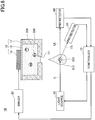
- FIG. 1 is a schematic diagram exemplifying the liquid droplet forming device according to the first embodiment.
- the liquid droplet forming device 1 includes a liquid droplet discharger 10; a driver 20; a light source 30; a photodetector 60; and a controller 70.
- the droplet discharger is not particularly limited; however, there are an inkjet head based on a piezoelectric pressure method using a piezoelectric element, an inkjet head based on a thermal method using a heater, an inkjet head based on an electrostatic method such that a liquid is pulled by electrostatic attraction, etc.
- the piezoelectric pressure method is favorable in that a damage on fluorescent particles 350 by heat or an electric field is relatively small.
- the liquid droplet discharger 10 includes a liquid chamber 11, a membrane 12, and a drive element 13.
- the liquid droplet discharger 10 is capable of discharging, as a liquid droplet, a particle suspension liquid 300 in which the fluorescent particles 350 are suspended (the fluorescent particles 350 are dispersed).
- the liquid chamber 11 is a liquid reservoir for reserving the particle suspension liquid 300 in which the fluorescent particles 350 are suspended, and a nozzle 111, which is a through hole, is formed at a bottom surface side.
- the liquid chamber 11 can be formed of, for example, a metal, silicon, ceramic, etc.
- the fluorescent particles 350 there are inorganic fine particles and organic polymer particles, etc., that are dyed with a fluorescent dye.
- the membrane 12 is a film-shaped component that is secured to an upper end part of the liquid chamber 11.
- a planar shape of the membrane 12 may be, for example, a circular shape; however, the planar shape may be an elliptical shape, or a rectangular shape, etc.
- the drive element 13 is formed on an upper surface side of the membrane 12.
- a shape of the drive element 13 can be designed to be adjusted to a shape of the membrane 12. For example, if a planar shape of the membrane 12 is a circular shape, it is preferable to form the drive element 13 having a circular shape.
- the membrane 12 By supplying a drive signal from the driver 20 to the drive element 13, the membrane 12 can be vibrated. By the vibration of the membrane 12, a liquid droplet 310 including a fluorescent particle 350 can be caused to be discharged from the nozzle 111.
- a structure may be adopted such that electrodes for applying a voltage are formed on an upper surface and a lower surface of the piezoelectric material.
- the piezoelectric material for example, lead zirconate titanate (PZT) can be used.
- PZT lead zirconate titanate
- various types of piezoelectric materials can be used, such as bismuth iron oxide, metal niobate, barium titanate, or a material obtained by adding a metal or a different oxide to these materials.
- the light source 30 emits light L to the flying liquid droplet 310.
- flying refers to a state of the liquid droplet 310 from being discharged from the liquid droplet discharger 10 until the liquid droplet 310 is dropped onto a drop target object.
- the flying droplet 310 has an approximate circular shape at a position at which the light L is irradiated.
- a beam shape of the light L is an approximate circular shape.
- a beam diameter of the light L is preferably approximately from 10 times to 100 times of the diameter of the liquid droplet 310. The reason is to ensure that the light L from the light source 30 is irradiated onto the liquid droplet 310, even if the position of the liquid droplet 310 varies.
- the beam diameter of the light L significantly exceeds 100 times of the diameter of the liquid droplet 310. The reason is that energy density of the light irradiated onto the liquid droplet 310 is reduced, and the light quantity of the fluorescence Lf that is emitted as the excitation light of the light L is so reduced to be difficult to be detected by the photodetector 60.
- the light L emitted from the light source 30 be pulsed light; and, for example, a solid laser, a semiconductor laser, a dye laser, etc., can preferably be used.
- a pulse width may preferably be less than or equal to 10 ⁇ s, and more preferably be less than or equal to 1 ⁇ s.
- the energy per unit pulse largely depends on the optical system such as the presence or absence of convergence; however, the energy per unit pulse may preferably be greater than or equal to approximately 0.1 ⁇ J, and more preferably greater than or equal to 1 ⁇ J.
- the photodetector 60 receives the fluorescence Lf that is emitted by the fluorescent particle 350 by absorbing the light L as the excitation light. Since the fluorescence Lf is emitted in all directions from the fluorescent particle 350, the photodetector 60 can be located at any position at which the fluorescence Lf can be received. At this time, in order to enhance the contrast, the photodetector 60 may preferably be located at a position at which the light L emitted from the light source 30 does not directly enter.
- the photodetector 60 is not particularly limited, provided that the photodetector 60 is an element that can receive the fluorescence Lf emitted from the fluorescent particle 350.
- the photodetector 60 for example, there is one-dimensional element, such as a photodiode and a photo sensor. However, if highly sensitive measurement is required, a photomultiplier or an avalanche photodiode may preferably be used.
- a two-dimensional element may be used, such as a Charge Coupled Device (CCD), a Complementary Metal Oxide Semiconductor, or a gate CCD.
- the fluorescence Lf emitted by the fluorescent particle 350 is weaker than the light L emitted by the light source 30.
- a filter for attenuating the wavelength range of the light L may be installed at a front side (the light receiving surface side) of the photodetector 60.
- a very high contrast image of the fluorescent particle 350 can be obtained on the photodetector 60.
- the filter for example, a notch filter for attenuating a specific wave range including the wavelength of the light L can be used.
- the light L emitted from the light source 30 is preferably pulsed light.
- the light L emitted from the light source 30 may be continuously oscillating light.
- the photodetector 60 by controlling the photodetector 60 so that the photodetector 60 can capture the light at a timing at which the continuously oscillating light is irradiated onto the flying liquid droplet 310, the fluorescence Lf may be received by the photodetector 60.
- the controller 70 is provided with a function for controlling the driver 20 and the light source 30. Additionally, the controller 70 is provided with a function for obtaining information based on the light quantity received by the photodetector 60 and detecting a number of the fluorescent particles 350 (including a case of zero) included in the liquid droplet 310. In the following, by referring to FIGS. 2 through 4 , the operation of the liquid droplet forming device 1 is described, which includes the operation of the controller 70.
- FIG. 2 is a diagram exemplifying hardware blocks of the controller of FIG. 1 .
- FIG. 3 is a diagram exemplifying functional blocks of the controller of FIG. 1 .
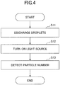
- FIG. 4 is an example of a flowchart illustrating the operation of the liquid droplet forming device according to the first embodiment.
- the controller 70 includes a CPU 71; a ROM 72; a RAM 73; an I/F 74; and a bus line 75.
- the CPU 71, the ROM 72, the RAM 73, and the I/F 74 are mutually coupled through the bus line 75.
- the CPU 71 controls each function of the controller 70.
- the ROM 72 that is a storage stores a program that is executed by the CPU 71 to control each function of the controller 70 and various types of information.
- the RAM 73 that is a storage is used as a work area of the CPU 71.
- the RAM 73 is capable of temporarily storing predetermined information.
- the I/F 74 is an interface for connecting the liquid droplet forming device 1 to another device.
- the liquid droplet forming device 1 may be coupled to an external network through the I/F 74.
- the controller 70 includes, as functional blocks, a discharge controller 701; a light source controller 702; and a particle number detector 703.
- the discharge controller 701 of the controller 70 outputs a discharge command to the driver 20.
- the driver 20 that receives the discharge command from the discharge controller 701 causes the membrane 12 to vibrate by supplying a drive signal to the drive element 13.
- the membrane 12 By vibration of the membrane 12, the liquid droplet 310 including the fluorescent particle 350 is discharged from the nozzle 111.
- step S12 the light source controller 702 of the controller 70, while being synchronized with discharging of the liquid droplet 310 (while being synchronized with the drive signal supplied to the liquid droplet discharger 10 from the driver 20), outputs a command for turning on the light source 30.
- the light source 30 is turned on, and the light L is irradiated onto the flying liquid droplet 310.
- synchronized does not mean that the light is emitted at the same time as the liquid droplet discharger 10 discharges the liquid droplet 310 (at the same time as the driver 20 supplies the drive signal to the liquid droplet discharger 10), but synchronized means that the light source 30 emits light at a timing at which the flying liquid droplet 310 reaches a predetermined position so that the light L is irradiated onto the liquid droplet 310.
- the light source controller 702 controls the light source 30 so that emission of the light is delayed by a predetermined time with respect to discharging of the liquid droplet 310 by the liquid droplet discharger 10 (the drive signal supplied to the liquid droplet discharger 10 from the driver 20).
- the velocity v of the liquid droplet 310 discharged at a moment at which the drive signal is supplied to the liquid droplet discharge 10 is measured in advance. Then, based on the measured velocity v, the time t from discharging of the liquid droplet 310 until the liquid droplet 310 reaches the predetermined position is calculated, and the timing for emitting the light by the light source 30 is delayed by t with respect to the timing for supplying the drive signal to the liquid droplet discharger 10. As a result, favorable light emission control is enabled, and it can be ensured to irradiate the light from the light source 30 onto the liquid droplet 310.
- the particle number detector 703 of the controller 70 detects a number of fluorescent particles 350 included in the liquid droplet 310 (which includes a case of zero) based on the information from the photodetector 60.
- the information from the photodetector 60 may be a brightness value (the light quantity) or an area value of the fluorescent particles 350.
- the particle number detector 703 is capable of counting a number of the fluorescent particles 350, for example, by comparing a light quantity received by the photodetector 60 and a preconfigured threshold value.
- a one-dimensional element or a two-dimensional element may be used as the photodetector 60.
- the particle number detector 703 may use a method of performing image processing for calculating the brightness value or the area of the fluorescent particles 350 based on the two-dimensional image obtained from the photodetector 60. In this case, the particle number detector 703 can count the number of the fluorescent particles 350 by calculating the brightness value or the area of the fluorescent particles 350 by image processing, and by comparing the calculated brightness value or the calculated area value with a preconfigured threshold value.
- the fluorescent particles 350 may be cells or stained cells.
- a stained cell is a cell stained with a fluorescent dye or a cell capable of expressing a fluorescent protein.
- the photodetector 60 receives autofluorescence of the cells, and the particle number detector 703 counts the number of the fluorescent particles 350 included in the liquid droplet 310.
- fluorescent dyes include cell tracker orange and cell tracker red.
- fluorescent protein examples include green fluorescent protein (GFP; green fluorescent protein), read fluorescent protein (RFP; read fluorescent protein); and yellow fluorescent protein (YFP; yellow fluorescent protein).
- a drive signal is supplied from the driver 20 to the liquid droplet discharger 10 reserving the particle suspension liquid 300 in which the fluorescent particles 350 are suspended so as to discharge the liquid droplet 310 including the fluorescent particles 350, and the light L from the light source 30 is irradiated onto the flying droplet 310.
- the fluorescent particles 350 included in the flying liquid droplet 310 emit fluorescence Lf using the light L as the excitation light, and the photodetector 60 receives the fluorescence Lf.
- the particle number detector 703 counts the number of the fluorescent particles 350 included in the flying liquid droplet 310.
- the droplet forming device 1 detection accuracy of the number of the fluorescent particles 350 can be enhanced compared to usual one because the number of the fluorescent particles 350 included in the flying liquid droplet 310 is actually observed on the spot. Additionally, the light L is irradiated onto the fluorescent particles 350 included in the flying liquid droplet 310 to emit the fluorescence Lf, and the fluorescence Lf is received by the photodetector 60. As a result, a high contrast image of the fluorescent particles 350 can be obtained, and a frequency of occurrence of erroneous detection of the number of the fluorescent particles 350 can be reduced.
- the modified example 1 of the first embodiment an example of the liquid droplet forming device is illustrated in which the configuration of the part of detecting the fluorescence emitted by the fluorescent particles 350 is modified. Note that, in the modified example 1 of the first embodiment, the description of a component that is the same as that of the above-described embodiment may be omitted.
- FIG. 5 is a schematic diagram exemplifying the liquid droplet forming device according to the modified example 1 of the first embodiment.
- the liquid droplet forming device 1A differs from the liquid droplet forming device 1 (see FIG. 1 ) in the point that a mirror 40 is provided in front of the photodetector 60.
- the degrees of freedom on the layout of the photodetector 60 can be enhanced.
- interference between the drop target object and the optical system (especially, the photodetector 60) of the droplet forming device 1 may occur in the layout of FIG. 1 .
- the layout of FIG. 5 occurrence of the interference can be avoided.
- a distance (gap) between the drop target object on which the liquid droplet 310 drops and the nozzle 111 can be reduced, and the variation in the dropping positions can be reduced. As a result, dispensing accuracy can be enhanced.
- the modified example 2 of the first embodiment another example of the liquid droplet forming device is illustrated in which the configuration of the part of detecting the fluorescence emitted by the fluorescent particles 350 is modified. Note that, in the modified example 2 of the first embodiment, the description of the component that is the same as that of the above-described embodiment may be omitted.
- FIG. 6 is a schematic diagram exemplifying the liquid droplet forming device according to the second modified example of the first embodiment.
- the liquid droplet forming device 1B differs from the liquid droplet forming device 1 (see FIG. 1 ) in the point that, in addition to the photodetector 60 for receiving the fluorescence Lf 1 emitted from the fluorescent particles 350, a photodetector 61 for receiving the fluorescence Lf 2 emitted from the fluorescent particles 350 is provided.
- the fluorescence Lf 1 and the fluorescence Lf 2 represent parts of the fluorescence emitted in all directions from the fluorescent particles 350.
- the photodetectors 60 and 61 can be located at any positions at which the fluorescence emitted from the fluorescent particles 350 in different directions can be received, respectively.
- three or more photodetectors may be arranged at positions at which the fluorescence emitted from the fluorescent particles 350 in different directions can be received, respectively.
- the photodetectors may be of the same specification or of the different specifications.
- the particle number detector 703 may erroneously detect the number of the fluorescent particles 350 included in the liquid droplet 310 (a count error occurs) due to overlapping of the fluorescent particles 350.
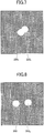
- FIG. 7 and FIG. 8 are diagrams exemplifying cases in which two fluorescent particles are included in the flying liquid droplets.
- cases are possible, such as a case, as shown in FIG. 7 , in which the fluorescent particle 350 1 and the fluorescent particle 350 2 overlap, and a case, as shown in FIG. 8 , in which the fluorescent particle 350 1 and fluorescent particle 350 2 do not overlap.
- the effect of overlapping of the fluorescent particles can be reduced.
- the particle number detector 703 can detect a number of fluorescent particles by calculating a brightness value or an area value of the fluorescent particles by image processing, and by comparing the calculated brightness value or the calculated area value with a preconfigured threshold value.
- n is greater than or equal to 2
- overlapping among particles may occur, and the actually measured brightness value becomes L ⁇ Le ⁇ nL (the shaded portion in FIG. 9 ).
- the threshold value may be adjusted so that (nL - L/2) ⁇ the threshold value ⁇ (nL + L/2).
- a plurality of photodetector is installed, by adopting a data item indicating the maximum value among data items obtained from the photodetectors, respectively, occurrence of a count error can be suppressed.
- an area value may be used.
- the number of the particles may be determined by an algorithm for estimating the particle numbers.
- the droplet forming device 1B can further reduce a frequency of occurrence of the erroneous detection of the numbers of the fluorescent particles 350 because the droplet forming device 1B includes a plurality of photodetectors for receiving fluorescence emitted by the fluorescent particles 350 in the respective different directions.
- the modified example 3 of the first embodiment another example of the liquid droplet forming device is illustrated in which the configuration of a part for detecting fluorescence emitted by the fluorescent particles 350 is modified. Note that, in the modified example 3 of the first embodiment, the description of the component that is the same as that of the above-described embodiment may be omitted.
- FIG. 10 is a schematic diagram exemplifying the liquid droplet forming device according to the modified example 3 of the first embodiment, in which a part of the liquid droplet forming device is viewed from an upper part of the liquid droplet forming device.
- the liquid droplet forming device 1C differs from the liquid droplet forming device 1 (see FIG. 1 ) in a point that the fluorescence Lf emitted from the fluorescent particles 350 is received by the photodetector 62 through a lens 50.
- the photodetector 62 has a structure such that a plurality of photodetectors is formed in an array.
- the fluorescence Lf from the fluorescent particles 350 are guided to the respective photodetectors forming the photodetector 62 by the lens 50.
- a lens with a high numerical aperture may preferably be used as the lens 50.
- NA Numerical Aperture
- an objective lens or an f ⁇ lens is preferable because light can be caused to orthogonally enter the photodetector 62, and positional dependence on the element can be prevented from occurring.
- the objective lens is a lens with which an enlarged image with little aberration cab be obtained.
- the photodetector 62 for example, a CCD array, a CMOS array, a photodiode array, etc., can be used. From a perspective of sensitivity and time response, it is most preferable to use a photodiode array.
- the fluorescence emitted by the fluorescent particles 350 in different directions can be received by the photodetectors forming the photodetector 62.
- a size of the liquid droplet forming device 1C can further be reduced.
- FIG. 11 is a schematic diagram exemplifying the liquid droplet forming device according to the modified example 4 of the first embodiment, in which a part of the liquid droplet forming device is viewed from an upper part of the liquid droplet forming device.
- the liquid droplet forming device 1D differs from the liquid droplet forming device 1 (see FIG. 1 ) in a point that fluorescence emitted from the fluorescent particles 350 is received by the photodetector 60 through a plurality of mirrors 41 and 42 and a plurality of lenses 51 through 53.
- fluorescence Lf 1 emitted from the fluorescent particles 350 is reflected by the mirror 41 to enter the lens 51, and further enters the lens 53 to form an image on the photodetector 60.
- the fluorescence Lf 2 that is emitted by the fluorescent particles 350 in a direction that is different from that of the fluorescence Lf 1 is reflected by the mirror 42 to enter the lens 52, and further enters the lens 53 to form an image on the photodetector 60.
- the photodetector 60 a two-dimensional array of photodetectors can be used.
- images from a plurality of directions can be formed on the single photodetector 60, and a frequency of occurrence of erroneous detection of the number of fluorescent particles 350 by the particle number detector 703 can be reduced with an inexpensive configuration.
- FIG. 12 is a schematic diagram exemplifying the liquid droplet forming device according to the modified example 5 of the first embodiment.
- the liquid droplet forming device 1E differs from the liquid droplet forming device 1 (see FIG. 1 ) in the point that the liquid droplet discharger 10 is replaced with a liquid droplet discharger 10E.
- the liquid droplet discharger 10E includes a liquid chamber 11E; a membrane 12E; and a drive element 13E. At an upper part of the liquid chamber 11E, there is an atmospheric opening 115 for opening the inside of the liquid chamber 11E to the atmosphere, and the liquid chamber 11E is configured so that air bubbles mixed in the particle suspension liquid 300 can be discharged from the atmospheric opening 115.
- the membrane 12E is a film shaped component secured to a lower end of the liquid chamber 11E. At an approximate center of the membrane 12E, a nozzle 121 that is a through hole is formed, and the particle suspension liquid 300 reserved in the liquid chamber 11E is discharged as the liquid droplet 310 from the nozzle 121 by the vibration of the membrane 12E. Since the droplet 310 is formed by the vibration inertia of the membrane 12E, the particle suspension liquid 300 can be discharged even if the particle suspension liquid 300 has high surface tension (high viscosity).
- the planar shape of the membrane 12E may be, for example, a circular shape; however, the planar shape of the membrane 12E may be an elliptical shape or a rectangular shape.
- the material of the membrane 12E is not particularly limited; however, a material with certain stiffness may preferably be used because if the material is too soft, the membrane 12E easily vibrates so that it is difficult to immediately suppress the vibration at a time at which discharging is not performed.
- a material with certain stiffness may preferably be used as the material of the membrane 12E.
- a metal material, a ceramic material, or a polymer material with a certain degree of stiffness may be used.
- a material with low adhesion to cells and protein is preferable.
- adhesion of cells depends on a contact angle between the material and water.
- the material having high hydrophilicity or high hydrophobicity the adhesion of the cells is low.
- various types of metal materials and ceramics (metal oxides) may be used, and, as a material having high hydrophobicity, a fluorine resin can be used.
- the material surface may be coated with the above-described metal or metal oxide material, or the metal surface may be coated with a synthetic phospholipid polymer that simulates a cell membrane (for example, Lipidure, manufactured by NIPPON OIL CO. LTD.).
- the nozzle 121 may preferably be formed at an approximate center of the membrane 12E as a through hole with an approximate circular shape.
- the diameter of the nozzle 121 is not particularly limited; however, in order to avoid clogging of the nozzle 121 with the fluorescent particles 350, the diameter of the nozzle 121 may preferably be greater than or equal to the twice the size of the fluorescent particle 350.
- the diameter of the nozzle 121 may preferably be adjusted to be greater than or equal to 10 ⁇ m to 100 ⁇ m in accordance with the cells to be used because the size of the human cell is, in general, approximately from 5 ⁇ m to 50 ⁇ m.
- the diameter of the nozzle 121 may preferably be less than or equal to 200 ⁇ m. Namely, in the liquid droplet discharger 10E, the diameter of the nozzle 121 may be typically in a range from 10 ⁇ m to 200 ⁇ m.
- the drive element 13E is formed on a lower surface side of the membrane 12E.
- the shape of the drive element 13E can be designed to be adjusted to the shape of the membrane 12E.
- the drive element 13E with an annular planer shape (a ring shape) may preferably be formed around the nozzle 121.
- the drive method of the drive element 13E may be the same as that of the drive element 13.
- the driver 20 can selectively (e.g., alternately) apply, to the drive element 13E, a discharge waveform for causing the membrane 12E to vibrate to form the liquid droplet 310 and a stirring waveform for causing the membrane 12E to vibrate within a range in which the liquid droplet 310 is not formed.
- the vibration state of the membrane 12E (the extent of the vibration) can be controlled.
- the drive element 13E is formed on the lower surface side of the membrane 12E. Accordingly, when the membrane 12 is caused to vibrate by the drive element 13E, a flow in a direction from the lower part to the upper part of the liquid chamber 11E can be generated.
- the motion of the fluorescent particles 350 is a motion from the bottom to the top, and a convection current occurs within the liquid chamber 11E and the particle suspension liquid 300 including the fluorescent particles 350 is stirred.
- the precipitated and aggregated fluorescent particles 350 are uniformly dispersed inside the liquid chamber 11E.
- the driver 20 in addition to applying the discharge waveform to the drive element 13E, by controlling the vibration state of the membrane 12E, the driver 20 can cause the particle suspension liquid 300 reserved in the liquid chamber 11E to be discharged from the nozzle 121 as the liquid droplet 310. Further, in addition to applying the stirring waveform to the drive element 13, by controlling the vibration state of the membrane 12E, the driver 20 can stir the particle suspension liquid 300 reserved in the liquid chamber 11E. Note that, during stirring, no liquid droplet 310 is discharged from the nozzle 121.
- the fluorescent particles 350 can be prevented from precipitating and aggregating on the membrane 12E, and the fluorescent particles 350 can be uniformly dispersed in the particle suspension liquid 300. Accordingly, clogging of the nozzle 121 and variation in the number of the fluorescent particles 350 in the discharged liquid droplet 310 can be suppressed. As a result, the particle suspension liquid 300 including the fluorescent particles 350 can be stably discharged continuously as the liquid droplet 310 for a long time.
- air bubbles may be mixed in the particle suspension liquid 300 in the liquid chamber 11E.
- the atmospheric opening 115 is formed at the upper part of the liquid chamber 11E.
- the air bubbles mixed in the particle suspension liquid 300 can be discharged to the outside air through the atmospheric opening 115.
- the liquid droplets 310 can be continuously and stably formed without discarding a large amount of liquid for discharging the air bubbles.
- the membrane 12E may be oscillated within a range in which no liquid droplet is formed, so that air bubbles are actively moved upward in the liquid chamber 11E.
- the liquid droplet forming device 1 is used for a device for dispensing fluorescent particles into wells. Note that, in the second embodiment, the description of the component that is the same as that of the above-described embodiment may be omitted.
- FIG. 13 is a schematic diagram exemplifying a dispensing device according to the second embodiment.
- the dispensing device 2 includes the liquid droplet forming device 1; a base 700; a stage 800; and a controller 900.
- the base 700 is disposed on the stage 800, which is configured to be movable.
- a plurality of wells 710 (concave parts) are formed in which the droplets 310 discharged from the liquid droplet discharger 10 (see FIG. 1 ) of the liquid droplet forming device 1 are dropped.
- the controller 900 causes the stage 800 to be moved so as to control relative positional relation between the liquid droplet discharger 10 (see FIG. 1 ) of the liquid droplet forming device 1 and each of the wells 710.
- the liquid droplets 310 including the fluorescent particles 350 can be sequentially discharged from the liquid droplet discharger 10 (see FIG. 1 ) of the liquid droplet forming device 1 into the respective wells 710.
- the controller 900 may be configured to include, for example, a CPU, a ROM, a RAM, and a main memory. In this case, various types of functions of the controller 900 may be implemented by reading out a program stored in the ROM onto the main memory to be executed by the CPU. However, a part or whole of the controller 900 may be implemented only by hardware. Additionally, the controller 900 may be physically formed of a plurality of devices.
- FIG. 14 is an example of a flowchart illustrating an operation of the dispensing device according to the second embodiment.
- the liquid droplet discharger 10 (see FIG. 1 ) of the liquid droplet forming device 1 discharges a liquid droplet 310 toward a predetermined well 710.
- step S102 the particle number detector 703 (see FIG. 1 ) of the liquid droplet forming device 1 detects a number of the fluorescent particles 350 included in the flying liquid droplet 310, and transmits the detection result to the controller 900. If the detection result by the particle number detector 703 is not "greater than or equal to 1" (the case of zero), the operation of step S101 is repeated.
- step S102 if the detection result by the particle number detector 703 is "greater than or equal to 1," the process proceeds to step S103.
- step S103 the controller 900 controls the stage 800 to move the base 700 so that the liquid droplet discharger 10 (see FIG. 1 ) of the liquid droplet forming device 1 is positioned to face the next well 710. Subsequently, the process proceeds to step S101 to repeat the same operation.
- FIG. 15 is another example of a flowchart illustrating an operation of the dispensing device according to the second embodiment.
- step S101 after executing step S101 that is the same as that of FIG. 14 , first, the particle number detector 703 ( FIG. 1 ) of the liquid droplet forming device 1 detects, at step S202, the number of the fluorescent particles 350 included in the flying liquid droplet 310, and sends the detection result to the controller 900. The operation of step S101 is repeated until the detection result by the particle number detector 703 becomes "greater than or equal to three.”
- the detection accuracy of the particle number detector 703 may decrease. Accordingly, it is not required to configure the number of the fluorescent particles 350 included in the liquid droplet 310 discharged by once to be greater than or equal to three.
- the number of the fluorescent particles 350 included in the liquid droplet 310 discharged by once may be configured to be zero or one. In this case, the operation of step S101 is repeated until the total of the number of the fluorescent particles 350 included in the one or more liquid droplets 310 becomes greater than or equal to three.
- step S202 if the detection result by the particle number detector 703 is "greater than or equal to three," the process proceeds to step S103, and step S103 that is the same as that of FIG. 14 is executed. Subsequently, the process proceeds to step S101, and the same operation is repeated. As a result, the florescent particles 350 can be dispensed so that the number of the fluorescent particles 350 in each well 710 is greater than or equal to three.
- the function of moving the liquid droplet forming device 1 to a predetermined position along the stage 800 in the processes of FIG. 14 and FIG. 15 can be embedded, for example, as a program in the controller 900.
- the liquid droplet forming device 1 any one of the liquid droplet forming devices 1A through 1E may be used.
- images of fluorescent particles 350 obtained by the photodetector 60 are compared between a case (reference example) in which light L is irradiated onto a liquid droplet 310 including a particle 390 other than a fluorescent particle and a case (example) in which the light L is irradiated onto the liquid droplet 310 including a florescent particle 350.
- the results are illustrated in FIG. 16 through FIG. 19 .
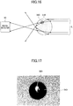
- FIG. 16 and FIG. 18 schematically illustrate a situation in which the light L is irradiated onto the liquid droplet 310
- FIG. 17 and FIG. 19 illustrate images captured by the photodetector 60.
- the flying liquid droplet 310 is shaded except for the central portion, and the particle 390 is hidden behind the liquid droplet 310. As a result, it is extremely difficult to detect the number of the particle 390 by the particle number detector 703.
- the fluorescent particle 350 is used as illustrated in FIG. 18 and FIG. 19 , the fluorescent particle 350 itself is an emitter for emitting fluorescence. Thus, an adverse situation does not occur such that the fluorescent particle 350 is hidden behind the liquid droplet 310 and that the fluorescent particle 350 is not recognized. Accordingly, the number of the fluorescent particles 350 can be accurately detected by the particle number detector 703.
- the fluorescence Lf from the fluorescent particles 350 is weaker than the light L from a laser.
- a filter 80 for attenuating the light L is installed in front of the photodetector 60.
- a very high contrast image of the fluorescent particles 350 can be captured.
- the filter 80 for example, a notch filter can be used that attenuates a specific wavelength range including the wavelength of the light L.
- a correct answer rate was evaluated for the detection (count) of the number of the fluorescent particles by the particle number detector 703. Specifically, evaluation was made while defining a count correct answer rate to be a ratio of cases in which a result of calculating the number of the fluorescent particles in the flying liquid droplet by the particle number detector 703 is equal to a result of visually confirming the number of the fluorescent particles after dropping (the true number of the fluorescent particles).
- FIG. 20 The evaluation results are shown in FIG. 20 .
- “A” indicates a result of performing evaluation using the liquid droplet forming device 1B illustrated in FIG. 6 .
- “B,” “C,” and “D” indicate results of performing evaluation using the liquid droplet forming device 1 illustrated in FIG. 1 .
- a high sensitivity camera sCMOS pco, edge, manufactured by Tokyo Instruments
- a YAG laser Explorer ONE-532-200-KE, manufactured by Spectra-Physics
- “ImageJ” which is image processing software was used as the particle number detector 703.
- fluorescent particle 350 "SPHERO Fluorescent Nile Red particles, 1% w/v, 10 to 14 ⁇ m, manufactured by Bay Biosciences” was used as the fluorescent particle 350.
- C a cell stained with a fluorescent dye (concentration 5 ⁇ 10 6 cells/mL, stained with cell tracker orange) was used as the fluorescent particle 350.
- D a cell that was not stained by a fluorescent dye was used as the fluorescent particle 350.
- the correct answer rate tends to decrease, as the number of the fluorescent particles included in the liquid droplet 310 increases. However, for "A,” a high correct answer rate that is greater than or equal to 90% is maintained.
- the correct answer rate is high, even if two fluorescent particles are included in the liquid droplet 310.
- the liquid droplet forming device 1B includes a plurality of photodetectors that can receive fluorescence emitted by the fluorescent particles 350 in different directions. Accordingly, it can be considered that erroneous detection due to overlapping of the fluorescent particles 350 can be reduced. Note that, if the correct answer rate is greater than or equal to 50%, practical use is possible.
- a configuration may be provided such that the liquid droplet forming device 1 can be independently moved in the X direction, Y direction, and Z direction. As a result, patterning of fluorescent particles within the XY plane and lamination of fluorescent particles in the Z direction can be easily performed.
Landscapes
- Chemical & Material Sciences (AREA)
- Health & Medical Sciences (AREA)
- General Physics & Mathematics (AREA)
- Pathology (AREA)
- Physics & Mathematics (AREA)
- Analytical Chemistry (AREA)
- Biochemistry (AREA)
- General Health & Medical Sciences (AREA)
- Life Sciences & Earth Sciences (AREA)
- Immunology (AREA)
- Dispersion Chemistry (AREA)
- Nuclear Medicine, Radiotherapy & Molecular Imaging (AREA)
- Engineering & Computer Science (AREA)
- Signal Processing (AREA)
- Investigating, Analyzing Materials By Fluorescence Or Luminescence (AREA)
- Coating Apparatus (AREA)
- Apparatus Associated With Microorganisms And Enzymes (AREA)
- Sampling And Sample Adjustment (AREA)
- Computer Vision & Pattern Recognition (AREA)
Abstract
Description
- The present invention relates to a liquid droplet forming device and a dispensing device.
- In recent years, with the development of stem cell technology, a technique has been developed such that an organism is formed by discharging a plurality of cells by inkjet. During discharging liquid droplets including particulate materials, which are represented by cells, it is important to detect what extent of particles are included in the discharged liquid droplet.
- As an example of the device provided with such a function, there is a discharging device that counts a number of particles included in a liquid object (see
Patent Document 1, for example). This discharging device is capable of counting a number of particles included in a liquid object that passes through a detector that is formed between a cavity and a nozzle of the discharging device. - Further, technology related to a fine particle measuring device has been known, which is for detecting fluorescence that is generated from fine particles in response to irradiation of excitation light onto a liquid droplet including the fine particles (see
Patent Document 2, for example). The fine particle measuring device is capable of detecting intensity of fluorescence generated by fine particles in a flying liquid droplet. - A liquid droplet forming device described in
Patent Document 1, however, counts a number of particles included in a liquid object immediately prior to flying, and the device does not directly count a number of particles included in a flying liquid droplet. The problem is that accuracy of detecting the number of particles included in the discharged liquid droplet is low because the number of the particles included in the liquid droplet immediately prior to flying may be or may not be equal to the number of the particles included in the flying liquid droplet. - Though the fine particle measuring device described in
Patent Document 2 can measure a shape or fluorescence intensity of a liquid droplet, the device does not count a number of particles in the liquid droplet. - The present invention is achieved in view of the above-described point, and an object is to provide a liquid droplet forming device with enhanced accuracy on detection of a number of particles included in a discharged liquid droplet.
- The liquid droplet forming device is required to include a liquid droplet discharger that discharges, as a liquid droplet, a particle suspension liquid in which one or more fluorescent particles are suspended; a light source for irradiating light onto the liquid droplet discharged from the liquid droplet discharger; a photodetector that receives fluorescence that is emitted by the one or more fluorescent particles included in the liquid droplet in response to the light as excitation light; and a particle number detector that detects a number of the one or more fluorescent particles included in the liquid droplet based on information from the photodetector.
- According to the disclosed technology, a liquid droplet forming device can be provided that is provided with enhanced accuracy on detecting a number of particles included in a discharged liquid droplet.
-
-
FIG. 1 is a schematic diagram exemplifying a liquid droplet forming device according to a first embodiment; -
FIG. 2 is a diagram exemplifying hardware blocks of a controller ofFIG. 1 ; -
FIG. 3 is a diagram exemplifying functional blocks of the controller ofFIG. 1 ; -
FIG. 4 is an example of a flowchart illustrating an operation of the liquid droplet forming device according to the first embodiment; -
FIG. 5 is a schematic diagram exemplifying a droplet forming device according to a modified example 1 of the first embodiment; -
FIG. 6 is a schematic diagram exemplifying a droplet forming device according to a modified example 2 of the first embodiment; -
FIG. 7 is a diagram (version 1) exemplifying a case in which two fluorescent particles are included in a flying liquid droplet; -
FIG. 8 is a diagram (version 2) exemplifying another case in which two fluorescent particles are included in a flying liquid droplet; -
FIG. 9 is a diagram exemplifying relation between a brightness value Li for a case in which no overlapping of particles occurs and a brightness value Le that is actually measured; -
FIG. 10 is a schematic diagram exemplifying a droplet forming device according to a modified example 3 of the first embodiment; -
FIG. 11 is a schematic diagram exemplifying a droplet forming device according to a modified example 4 of the first embodiment; -
FIG. 12 is a schematic diagram exemplifying a droplet forming device according to a modified example 5 of the first embodiment; -
FIG. 13 is a schematic diagram exemplifying a dispensing device according to a second embodiment; -
FIG. 14 illustrates an example of a flowchart illustrating an operation of the dispensing device according to the second embodiment; -
FIG. 15 illustrates another example of a flowchart illustrating an operation of the dispensing device according to the second embodiment; -
FIG. 16 is a diagram (version 1) illustrating an image of a particle other than a fluorescent particle captured by a photodetector; -
FIG. 17 is a diagram (version 2) illustrating the image of the particle other than the fluorescent particle captured by the photodetector; -
FIG. 18 is a diagram (version 1) illustrating an image of a fluorescent particle captured by the photodetector; -
FIG. 19 is a diagram (version 2) illustrating the image of the fluorescent particle captured by the photodetector; and -
FIG. 20 is a diagram illustrating a result of evaluation of a correct answer rate for detecting a number of fluorescent particles by a particle number detector. - In the following, embodiments for carrying out the invention are described by referring to the drawings. In the drawings, the same reference numerals may be attached to the same components, and duplicate description may be omitted.
- First, a liquid droplet forming device according to a first embodiment is described.
FIG. 1 is a schematic diagram exemplifying the liquid droplet forming device according to the first embodiment. Referring toFIG. 1 , the liquiddroplet forming device 1 includes aliquid droplet discharger 10; adriver 20; alight source 30; aphotodetector 60; and acontroller 70. - The droplet discharger is not particularly limited; however, there are an inkjet head based on a piezoelectric pressure method using a piezoelectric element, an inkjet head based on a thermal method using a heater, an inkjet head based on an electrostatic method such that a liquid is pulled by electrostatic attraction, etc. Among these, the piezoelectric pressure method is favorable in that a damage on
fluorescent particles 350 by heat or an electric field is relatively small. - The
liquid droplet discharger 10 includes aliquid chamber 11, amembrane 12, and adrive element 13. Theliquid droplet discharger 10 is capable of discharging, as a liquid droplet, aparticle suspension liquid 300 in which thefluorescent particles 350 are suspended (thefluorescent particles 350 are dispersed). - The
liquid chamber 11 is a liquid reservoir for reserving theparticle suspension liquid 300 in which thefluorescent particles 350 are suspended, and anozzle 111, which is a through hole, is formed at a bottom surface side. Theliquid chamber 11 can be formed of, for example, a metal, silicon, ceramic, etc. As thefluorescent particles 350, there are inorganic fine particles and organic polymer particles, etc., that are dyed with a fluorescent dye. - The
membrane 12 is a film-shaped component that is secured to an upper end part of theliquid chamber 11. A planar shape of themembrane 12 may be, for example, a circular shape; however, the planar shape may be an elliptical shape, or a rectangular shape, etc. - The
drive element 13 is formed on an upper surface side of themembrane 12. A shape of thedrive element 13 can be designed to be adjusted to a shape of themembrane 12. For example, if a planar shape of themembrane 12 is a circular shape, it is preferable to form thedrive element 13 having a circular shape. - By supplying a drive signal from the
driver 20 to thedrive element 13, themembrane 12 can be vibrated. By the vibration of themembrane 12, aliquid droplet 310 including afluorescent particle 350 can be caused to be discharged from thenozzle 111. - When a piezoelectric element is used as the
drive element 13, for example, a structure may be adopted such that electrodes for applying a voltage are formed on an upper surface and a lower surface of the piezoelectric material. In this case, by applying a voltage between the upper and lower electrodes of the piezoelectric element from thedriver 20, compressive stress can be applied in a lateral direction in the paper plane, and themembrane 12 can be vibrated in the vertical direction in the paper plane. As the piezoelectric material, for example, lead zirconate titanate (PZT) can be used. In addition to this, various types of piezoelectric materials can be used, such as bismuth iron oxide, metal niobate, barium titanate, or a material obtained by adding a metal or a different oxide to these materials. - The
light source 30 emits light L to theflying liquid droplet 310. Note that flying refers to a state of theliquid droplet 310 from being discharged from theliquid droplet discharger 10 until theliquid droplet 310 is dropped onto a drop target object. The flyingdroplet 310 has an approximate circular shape at a position at which the light L is irradiated. A beam shape of the light L is an approximate circular shape. - Here, a beam diameter of the light L is preferably approximately from 10 times to 100 times of the diameter of the
liquid droplet 310. The reason is to ensure that the light L from thelight source 30 is irradiated onto theliquid droplet 310, even if the position of theliquid droplet 310 varies. - However, it is not preferable that the beam diameter of the light L significantly exceeds 100 times of the diameter of the
liquid droplet 310. The reason is that energy density of the light irradiated onto theliquid droplet 310 is reduced, and the light quantity of the fluorescence Lf that is emitted as the excitation light of the light L is so reduced to be difficult to be detected by thephotodetector 60. - It is preferable that the light L emitted from the
light source 30 be pulsed light; and, for example, a solid laser, a semiconductor laser, a dye laser, etc., can preferably be used. When the light L is pulsed light, a pulse width may preferably be less than or equal to 10 µs, and more preferably be less than or equal to 1 µs. The energy per unit pulse largely depends on the optical system such as the presence or absence of convergence; however, the energy per unit pulse may preferably be greater than or equal to approximately 0.1 µJ, and more preferably greater than or equal to 1 µJ. - When the flying
liquid droplet 310 includes thefluorescent particle 350, thephotodetector 60 receives the fluorescence Lf that is emitted by thefluorescent particle 350 by absorbing the light L as the excitation light. Since the fluorescence Lf is emitted in all directions from thefluorescent particle 350, thephotodetector 60 can be located at any position at which the fluorescence Lf can be received. At this time, in order to enhance the contrast, thephotodetector 60 may preferably be located at a position at which the light L emitted from thelight source 30 does not directly enter. - The
photodetector 60 is not particularly limited, provided that thephotodetector 60 is an element that can receive the fluorescence Lf emitted from thefluorescent particle 350. As thephotodetector 60, for example, there is one-dimensional element, such as a photodiode and a photo sensor. However, if highly sensitive measurement is required, a photomultiplier or an avalanche photodiode may preferably be used. As thephotodetector 60, for example, a two-dimensional element may be used, such as a Charge Coupled Device (CCD), a Complementary Metal Oxide Semiconductor, or a gate CCD. - The fluorescence Lf emitted by the
fluorescent particle 350 is weaker than the light L emitted by thelight source 30. Thus, a filter for attenuating the wavelength range of the light L may be installed at a front side (the light receiving surface side) of thephotodetector 60. As a result, a very high contrast image of thefluorescent particle 350 can be obtained on thephotodetector 60. As the filter, for example, a notch filter for attenuating a specific wave range including the wavelength of the light L can be used. - As described above, the light L emitted from the
light source 30 is preferably pulsed light. However, the light L emitted from thelight source 30 may be continuously oscillating light. In this case, by controlling thephotodetector 60 so that thephotodetector 60 can capture the light at a timing at which the continuously oscillating light is irradiated onto the flyingliquid droplet 310, the fluorescence Lf may be received by thephotodetector 60. - The
controller 70 is provided with a function for controlling thedriver 20 and thelight source 30. Additionally, thecontroller 70 is provided with a function for obtaining information based on the light quantity received by thephotodetector 60 and detecting a number of the fluorescent particles 350 (including a case of zero) included in theliquid droplet 310. In the following, by referring toFIGS. 2 through 4 , the operation of the liquiddroplet forming device 1 is described, which includes the operation of thecontroller 70. -
FIG. 2 is a diagram exemplifying hardware blocks of the controller ofFIG. 1 .FIG. 3 is a diagram exemplifying functional blocks of the controller ofFIG. 1 .FIG. 4 is an example of a flowchart illustrating the operation of the liquid droplet forming device according to the first embodiment. - Referring to
FIG. 2 , thecontroller 70 includes aCPU 71; aROM 72; aRAM 73; an I/F 74; and abus line 75. TheCPU 71, theROM 72, theRAM 73, and the I/F 74 are mutually coupled through thebus line 75. - The
CPU 71 controls each function of thecontroller 70. TheROM 72 that is a storage stores a program that is executed by theCPU 71 to control each function of thecontroller 70 and various types of information. TheRAM 73 that is a storage is used as a work area of theCPU 71. TheRAM 73 is capable of temporarily storing predetermined information. The I/F 74 is an interface for connecting the liquiddroplet forming device 1 to another device. The liquiddroplet forming device 1 may be coupled to an external network through the I/F 74. - Referring to
FIG. 3 , thecontroller 70 includes, as functional blocks, adischarge controller 701; alight source controller 702; and aparticle number detector 703. - By referring to
FIG. 3 andFIG. 4 , detection of a number of particles by the liquiddroplet forming device 1 is described. First, at step S11, thedischarge controller 701 of thecontroller 70 outputs a discharge command to thedriver 20. Thedriver 20 that receives the discharge command from thedischarge controller 701 causes themembrane 12 to vibrate by supplying a drive signal to thedrive element 13. By vibration of themembrane 12, theliquid droplet 310 including thefluorescent particle 350 is discharged from thenozzle 111. - Next, at step S12, the
light source controller 702 of thecontroller 70, while being synchronized with discharging of the liquid droplet 310 (while being synchronized with the drive signal supplied to theliquid droplet discharger 10 from the driver 20), outputs a command for turning on thelight source 30. As a result, thelight source 30 is turned on, and the light L is irradiated onto the flyingliquid droplet 310. - Here, synchronized does not mean that the light is emitted at the same time as the
liquid droplet discharger 10 discharges the liquid droplet 310 (at the same time as thedriver 20 supplies the drive signal to the liquid droplet discharger 10), but synchronized means that thelight source 30 emits light at a timing at which the flyingliquid droplet 310 reaches a predetermined position so that the light L is irradiated onto theliquid droplet 310. Namely, thelight source controller 702 controls thelight source 30 so that emission of the light is delayed by a predetermined time with respect to discharging of theliquid droplet 310 by the liquid droplet discharger 10 (the drive signal supplied to theliquid droplet discharger 10 from the driver 20). - For example, the velocity v of the
liquid droplet 310 discharged at a moment at which the drive signal is supplied to theliquid droplet discharge 10 is measured in advance. Then, based on the measured velocity v, the time t from discharging of theliquid droplet 310 until theliquid droplet 310 reaches the predetermined position is calculated, and the timing for emitting the light by thelight source 30 is delayed by t with respect to the timing for supplying the drive signal to theliquid droplet discharger 10. As a result, favorable light emission control is enabled, and it can be ensured to irradiate the light from thelight source 30 onto theliquid droplet 310. - Next, at step S13, the
particle number detector 703 of thecontroller 70 detects a number offluorescent particles 350 included in the liquid droplet 310 (which includes a case of zero) based on the information from thephotodetector 60. Here, the information from thephotodetector 60 may be a brightness value (the light quantity) or an area value of thefluorescent particles 350. - The
particle number detector 703 is capable of counting a number of thefluorescent particles 350, for example, by comparing a light quantity received by thephotodetector 60 and a preconfigured threshold value. In this case, a one-dimensional element or a two-dimensional element may be used as thephotodetector 60. - When a two-dimensional element is used as the
photodetector 60, theparticle number detector 703 may use a method of performing image processing for calculating the brightness value or the area of thefluorescent particles 350 based on the two-dimensional image obtained from thephotodetector 60. In this case, theparticle number detector 703 can count the number of thefluorescent particles 350 by calculating the brightness value or the area of thefluorescent particles 350 by image processing, and by comparing the calculated brightness value or the calculated area value with a preconfigured threshold value. - Note that the
fluorescent particles 350 may be cells or stained cells. A stained cell is a cell stained with a fluorescent dye or a cell capable of expressing a fluorescent protein. When thefluorescent particles 350 are cells, thephotodetector 60 receives autofluorescence of the cells, and theparticle number detector 703 counts the number of thefluorescent particles 350 included in theliquid droplet 310. - In stained cells, examples of fluorescent dyes include cell tracker orange and cell tracker red. Examples of fluorescent protein include green fluorescent protein (GFP; green fluorescent protein), read fluorescent protein (RFP; read fluorescent protein); and yellow fluorescent protein (YFP; yellow fluorescent protein).
- As described above, in the liquid
droplet forming device 1, a drive signal is supplied from thedriver 20 to theliquid droplet discharger 10 reserving theparticle suspension liquid 300 in which thefluorescent particles 350 are suspended so as to discharge theliquid droplet 310 including thefluorescent particles 350, and the light L from thelight source 30 is irradiated onto the flyingdroplet 310. Then, thefluorescent particles 350 included in the flyingliquid droplet 310 emit fluorescence Lf using the light L as the excitation light, and thephotodetector 60 receives the fluorescence Lf. Further, based on the information from thephotodetector 60, theparticle number detector 703 counts the number of thefluorescent particles 350 included in the flyingliquid droplet 310. - Namely, in the
droplet forming device 1, detection accuracy of the number of thefluorescent particles 350 can be enhanced compared to usual one because the number of thefluorescent particles 350 included in the flyingliquid droplet 310 is actually observed on the spot. Additionally, the light L is irradiated onto thefluorescent particles 350 included in the flyingliquid droplet 310 to emit the fluorescence Lf, and the fluorescence Lf is received by thephotodetector 60. As a result, a high contrast image of thefluorescent particles 350 can be obtained, and a frequency of occurrence of erroneous detection of the number of thefluorescent particles 350 can be reduced. - In the modified example 1 of the first embodiment, an example of the liquid droplet forming device is illustrated in which the configuration of the part of detecting the fluorescence emitted by the
fluorescent particles 350 is modified. Note that, in the modified example 1 of the first embodiment, the description of a component that is the same as that of the above-described embodiment may be omitted. -
FIG. 5 is a schematic diagram exemplifying the liquid droplet forming device according to the modified example 1 of the first embodiment. Referring toFIG. 5 , the liquiddroplet forming device 1A differs from the liquid droplet forming device 1 (seeFIG. 1 ) in the point that amirror 40 is provided in front of thephotodetector 60. - As described above, in the liquid
droplet forming device 1A, by arranging themirror 40 in front of thephotodetector 60, the degrees of freedom on the layout of thephotodetector 60 can be enhanced. - For example, when the
nozzle 111 and the drop target object are brought close to each other, interference between the drop target object and the optical system (especially, the photodetector 60) of thedroplet forming device 1 may occur in the layout ofFIG. 1 . However, by adopting the layout ofFIG. 5 , occurrence of the interference can be avoided. - Namely, by modifying the layout of the
photodetector 60 as shown inFIG. 5 , a distance (gap) between the drop target object on which theliquid droplet 310 drops and thenozzle 111 can be reduced, and the variation in the dropping positions can be reduced. As a result, dispensing accuracy can be enhanced. - In the modified example 2 of the first embodiment, another example of the liquid droplet forming device is illustrated in which the configuration of the part of detecting the fluorescence emitted by the
fluorescent particles 350 is modified. Note that, in the modified example 2 of the first embodiment, the description of the component that is the same as that of the above-described embodiment may be omitted. -
FIG. 6 is a schematic diagram exemplifying the liquid droplet forming device according to the second modified example of the first embodiment. Referring toFIG. 6 , the liquiddroplet forming device 1B differs from the liquid droplet forming device 1 (seeFIG. 1 ) in the point that, in addition to thephotodetector 60 for receiving the fluorescence Lf1 emitted from thefluorescent particles 350, aphotodetector 61 for receiving the fluorescence Lf2 emitted from thefluorescent particles 350 is provided. - Here, the fluorescence Lf1 and the fluorescence Lf2 represent parts of the fluorescence emitted in all directions from the
fluorescent particles 350. Thephotodetectors fluorescent particles 350 in different directions can be received, respectively. Here, three or more photodetectors may be arranged at positions at which the fluorescence emitted from thefluorescent particles 350 in different directions can be received, respectively. The photodetectors may be of the same specification or of the different specifications. - If there is one photodetector and a plurality of
fluorescent particles 350 is included in the flyingliquid droplet 310, theparticle number detector 703 may erroneously detect the number of thefluorescent particles 350 included in the liquid droplet 310 (a count error occurs) due to overlapping of thefluorescent particles 350. -
FIG. 7 and FIG. 8 are diagrams exemplifying cases in which two fluorescent particles are included in the flying liquid droplets. For example, cases are possible, such as a case, as shown inFIG. 7 , in which thefluorescent particle 3501 and thefluorescent particle 3502 overlap, and a case, as shown inFIG. 8 , in which thefluorescent particle 3501 andfluorescent particle 3502 do not overlap. By providing two or more photodetectors, the effect of overlapping of the fluorescent particles can be reduced. - As described above, the
particle number detector 703 can detect a number of fluorescent particles by calculating a brightness value or an area value of the fluorescent particles by image processing, and by comparing the calculated brightness value or the calculated area value with a preconfigured threshold value. - When two or more photodetectors are installed, by adopting, among brightness values or area values obtained from the photodetectors, the data indicating the maximum value, occurrence of a count error can be suppressed. This is described in more detail by referring to
FIG. 9 . -
FIG. 9 is a diagram exemplifying the relation between the brightness value Li when there is no overlapping among particles and the actually measured brightness value Le. As illustrated inFIG. 9 , if there is no overlapping among particles, Le = Li. For example, if the brightness value of one particle is L, Le = L when the number of particles/droplet = 1; and Le = nL when the number of particles/droplet = n (n: natural number). - However, in practice, if n is greater than or equal to 2, overlapping among particles may occur, and the actually measured brightness value becomes L ≤ Le ≤ nL (the shaded portion in
FIG. 9 ). Thus, if the number of particles/droplet = n, for example, the threshold value may be adjusted so that (nL - L/2) ≤ the threshold value ≤ (nL + L/2). Then, if a plurality of photodetector is installed, by adopting a data item indicating the maximum value among data items obtained from the photodetectors, respectively, occurrence of a count error can be suppressed. Note that, instead of the brightness value, an area value may be used. - Furthermore, if a plurality of photodetectors is installed, based on a plurality of shape data items that can be obtained, the number of the particles may be determined by an algorithm for estimating the particle numbers.
- As described above, the
droplet forming device 1B can further reduce a frequency of occurrence of the erroneous detection of the numbers of thefluorescent particles 350 because thedroplet forming device 1B includes a plurality of photodetectors for receiving fluorescence emitted by thefluorescent particles 350 in the respective different directions. - In the modified example 3 of the first embodiment, another example of the liquid droplet forming device is illustrated in which the configuration of a part for detecting fluorescence emitted by the
fluorescent particles 350 is modified. Note that, in the modified example 3 of the first embodiment, the description of the component that is the same as that of the above-described embodiment may be omitted. -
FIG. 10 is a schematic diagram exemplifying the liquid droplet forming device according to the modified example 3 of the first embodiment, in which a part of the liquid droplet forming device is viewed from an upper part of the liquid droplet forming device. Referring toFIG. 10 , the liquiddroplet forming device 1C differs from the liquid droplet forming device 1 (seeFIG. 1 ) in a point that the fluorescence Lf emitted from thefluorescent particles 350 is received by thephotodetector 62 through alens 50. - The
photodetector 62 has a structure such that a plurality of photodetectors is formed in an array. The fluorescence Lf from thefluorescent particles 350 are guided to the respective photodetectors forming thephotodetector 62 by thelens 50. - A lens with a high numerical aperture (NA: Numerical Aperture) may preferably be used as the
lens 50. In particular, an objective lens or an fθ lens is preferable because light can be caused to orthogonally enter thephotodetector 62, and positional dependence on the element can be prevented from occurring. Here, the objective lens is a lens with which an enlarged image with little aberration cab be obtained. The fθ lens is a lens such that y = fθ holes when an image height is y, a focal length is f, and a light incident angle to the lens is θ. As thephotodetector 62, for example, a CCD array, a CMOS array, a photodiode array, etc., can be used. From a perspective of sensitivity and time response, it is most preferable to use a photodiode array. - In the liquid
droplet forming device 1C, by suitably arranging theliquid droplet 310 and thelens 50, the fluorescence emitted by thefluorescent particles 350 in different directions can be received by the photodetectors forming thephotodetector 62. As a result, a size of the liquiddroplet forming device 1C can further be reduced. - In the modified example 4 of the first embodiment, another example of the liquid droplet forming device is illustrated in which a configuration of a part of detecting fluorescence emitted by the
fluorescent particles 350 is modified. In the fourth example of the first embodiment, the description of the component that is the same as that of the above-described embodiment may be omitted. -
FIG. 11 is a schematic diagram exemplifying the liquid droplet forming device according to the modified example 4 of the first embodiment, in which a part of the liquid droplet forming device is viewed from an upper part of the liquid droplet forming device. Referring toFIG. 11 , the liquiddroplet forming device 1D differs from the liquid droplet forming device 1 (seeFIG. 1 ) in a point that fluorescence emitted from thefluorescent particles 350 is received by thephotodetector 60 through a plurality ofmirrors lenses 51 through 53. - In the liquid
droplet forming device 1D, fluorescence Lf1 emitted from thefluorescent particles 350 is reflected by themirror 41 to enter thelens 51, and further enters thelens 53 to form an image on thephotodetector 60. The fluorescence Lf2 that is emitted by thefluorescent particles 350 in a direction that is different from that of the fluorescence Lf1 is reflected by themirror 42 to enter thelens 52, and further enters thelens 53 to form an image on thephotodetector 60. As thephotodetector 60, a two-dimensional array of photodetectors can be used. - As described above, by arranging the plurality of
mirrors lenses 51 through 53 at the respective positions so that the fluorescence emitted by thefluorescent particles 350 in different directions can be entered, and by using the two-dimensional array of photodetectors as thephotodetector 60, an image of thefluorescent particles 350 viewed from the right half can be captured by the right half inFIG. 11 , and an image of thefluorescent particles 350 viewed from the left half can be captured by the left half. - As a result, images from a plurality of directions can be formed on the
single photodetector 60, and a frequency of occurrence of erroneous detection of the number offluorescent particles 350 by theparticle number detector 703 can be reduced with an inexpensive configuration. - In the modified example 5 of the first embodiment, an example of the liquid droplet forming device is illustrated in which the configuration of the liquid droplet discharger is modified. In the modified example 5 of the first embodiment, the description of the component that is the same as that of the above-described embodiment may be omitted.
-
FIG. 12 is a schematic diagram exemplifying the liquid droplet forming device according to the modified example 5 of the first embodiment. Referring toFIG. 12 , the liquiddroplet forming device 1E differs from the liquid droplet forming device 1 (seeFIG. 1 ) in the point that theliquid droplet discharger 10 is replaced with aliquid droplet discharger 10E. - The
liquid droplet discharger 10E includes aliquid chamber 11E; amembrane 12E; and adrive element 13E. At an upper part of theliquid chamber 11E, there is anatmospheric opening 115 for opening the inside of theliquid chamber 11E to the atmosphere, and theliquid chamber 11E is configured so that air bubbles mixed in theparticle suspension liquid 300 can be discharged from theatmospheric opening 115. - The
membrane 12E is a film shaped component secured to a lower end of theliquid chamber 11E. At an approximate center of themembrane 12E, anozzle 121 that is a through hole is formed, and theparticle suspension liquid 300 reserved in theliquid chamber 11E is discharged as theliquid droplet 310 from thenozzle 121 by the vibration of themembrane 12E. Since thedroplet 310 is formed by the vibration inertia of themembrane 12E, theparticle suspension liquid 300 can be discharged even if theparticle suspension liquid 300 has high surface tension (high viscosity). The planar shape of themembrane 12E may be, for example, a circular shape; however, the planar shape of themembrane 12E may be an elliptical shape or a rectangular shape. - The material of the
membrane 12E is not particularly limited; however, a material with certain stiffness may preferably be used because if the material is too soft, themembrane 12E easily vibrates so that it is difficult to immediately suppress the vibration at a time at which discharging is not performed. As the material of themembrane 12E, for example, a metal material, a ceramic material, or a polymer material with a certain degree of stiffness may be used. - Especially, when cells are used as the
fluorescent particles 350, a material with low adhesion to cells and protein is preferable. In general, adhesion of cells depends on a contact angle between the material and water. When the material has high hydrophilicity or high hydrophobicity, the adhesion of the cells is low. As a material having high hydrophilicity, various types of metal materials and ceramics (metal oxides) may be used, and, as a material having high hydrophobicity, a fluorine resin can be used. - Other examples of such a material include stainless steel, nickel, aluminum, silicon oxide, alumina, zirconia, etc. Other than this, it can be considered to lower cell adhesiveness by coating the material surface. For example, the material surface may be coated with the above-described metal or metal oxide material, or the metal surface may be coated with a synthetic phospholipid polymer that simulates a cell membrane (for example, Lipidure, manufactured by NIPPON OIL CO. LTD.).
- The
nozzle 121 may preferably be formed at an approximate center of themembrane 12E as a through hole with an approximate circular shape. In this case, the diameter of thenozzle 121 is not particularly limited; however, in order to avoid clogging of thenozzle 121 with thefluorescent particles 350, the diameter of thenozzle 121 may preferably be greater than or equal to the twice the size of thefluorescent particle 350. When thefluorescent particles 350 are, for example, animal cells, and, in particular, when thefluorescent particles 350 are human cells, the diameter of thenozzle 121 may preferably be adjusted to be greater than or equal to 10 µm to 100 µm in accordance with the cells to be used because the size of the human cell is, in general, approximately from 5 µm to 50 µm. - However, if the liquid droplet is too large, it is difficult to achieve the object of forming a fine liquid droplet. Thus, the diameter of the
nozzle 121 may preferably be less than or equal to 200 µm. Namely, in theliquid droplet discharger 10E, the diameter of thenozzle 121 may be typically in a range from 10 µm to 200 µm. - The
drive element 13E is formed on a lower surface side of themembrane 12E. The shape of thedrive element 13E can be designed to be adjusted to the shape of themembrane 12E. For example, if the planar shape of themembrane 12E is a circular shape, thedrive element 13E with an annular planer shape (a ring shape) may preferably be formed around thenozzle 121. The drive method of thedrive element 13E may be the same as that of thedrive element 13. - The
driver 20 can selectively (e.g., alternately) apply, to thedrive element 13E, a discharge waveform for causing themembrane 12E to vibrate to form theliquid droplet 310 and a stirring waveform for causing themembrane 12E to vibrate within a range in which theliquid droplet 310 is not formed. - For example, by shaping the discharge waveform and the stirring waveform to be rectangular waves, and by adjusting the drive voltage of the stirring waveform to be lower than the drive voltage of the discharge waveform, it can be prevented that a
liquid droplet 310 is formed by application of the stirring waveform. Namely, by adjusting the drive voltage to be high or low, the vibration state of themembrane 12E (the extent of the vibration) can be controlled. - In the
liquid droplet discharger 10E, thedrive element 13E is formed on the lower surface side of themembrane 12E. Accordingly, when themembrane 12 is caused to vibrate by thedrive element 13E, a flow in a direction from the lower part to the upper part of theliquid chamber 11E can be generated. - At this time, the motion of the
fluorescent particles 350 is a motion from the bottom to the top, and a convection current occurs within theliquid chamber 11E and theparticle suspension liquid 300 including thefluorescent particles 350 is stirred. By the flow from the bottom direction to the upper direction of theliquid chamber 11E, the precipitated and aggregatedfluorescent particles 350 are uniformly dispersed inside theliquid chamber 11E. - Namely, in addition to applying the discharge waveform to the
drive element 13E, by controlling the vibration state of themembrane 12E, thedriver 20 can cause theparticle suspension liquid 300 reserved in theliquid chamber 11E to be discharged from thenozzle 121 as theliquid droplet 310. Further, in addition to applying the stirring waveform to thedrive element 13, by controlling the vibration state of themembrane 12E, thedriver 20 can stir theparticle suspension liquid 300 reserved in theliquid chamber 11E. Note that, during stirring, noliquid droplet 310 is discharged from thenozzle 121. - As described above, by stirring the
particle suspension liquid 300 while theliquid droplet 310 is not formed, thefluorescent particles 350 can be prevented from precipitating and aggregating on themembrane 12E, and thefluorescent particles 350 can be uniformly dispersed in theparticle suspension liquid 300. Accordingly, clogging of thenozzle 121 and variation in the number of thefluorescent particles 350 in the dischargedliquid droplet 310 can be suppressed. As a result, theparticle suspension liquid 300 including thefluorescent particles 350 can be stably discharged continuously as theliquid droplet 310 for a long time. - Additionally, in the liquid
droplet forming device 1E, air bubbles may be mixed in theparticle suspension liquid 300 in theliquid chamber 11E. In this case, in the liquiddroplet forming device 1E, theatmospheric opening 115 is formed at the upper part of theliquid chamber 11E. Thus, the air bubbles mixed in theparticle suspension liquid 300 can be discharged to the outside air through theatmospheric opening 115. As a result, theliquid droplets 310 can be continuously and stably formed without discarding a large amount of liquid for discharging the air bubbles. - In other words, if air bubbles are mixed in the vicinity of the
nozzle 121, or if many air bubbles are mixed on themembrane 12E, the discharge state is affected. Accordingly, in order to stably forming liquid droplets for a long time, it is required to discharge the mixed air bubbles. Usually, air bubbles mixed on themembrane 12E move upward naturally or due to the vibration of themembrane 12E. However, theatmospheric opening 115 is formed in theliquid chamber 11E, and, thus, the mixed air bubbles can be discharged from theatmospheric opening 115. Accordingly, even if air bubbles are mixed in theliquid chamber 11E, a discharging failure can be prevented from occurring, and theliquid droplets 310 can be continuously and stably formed. - Note that, at a timing at which no liquid droplet is formed, the
membrane 12E may be oscillated within a range in which no liquid droplet is formed, so that air bubbles are actively moved upward in theliquid chamber 11E. - In the second embodiment, an example is illustrated such that the liquid
droplet forming device 1 is used for a device for dispensing fluorescent particles into wells. Note that, in the second embodiment, the description of the component that is the same as that of the above-described embodiment may be omitted. -
FIG. 13 is a schematic diagram exemplifying a dispensing device according to the second embodiment. Referring toFIG. 13 , thedispensing device 2 includes the liquiddroplet forming device 1; abase 700; astage 800; and acontroller 900. - In the
dispensing device 2, thebase 700 is disposed on thestage 800, which is configured to be movable. In thebase 700, a plurality of wells 710 (concave parts) are formed in which thedroplets 310 discharged from the liquid droplet discharger 10 (seeFIG. 1 ) of the liquiddroplet forming device 1 are dropped. Thecontroller 900 causes thestage 800 to be moved so as to control relative positional relation between the liquid droplet discharger 10 (seeFIG. 1 ) of the liquiddroplet forming device 1 and each of thewells 710. As a result, theliquid droplets 310 including thefluorescent particles 350 can be sequentially discharged from the liquid droplet discharger 10 (seeFIG. 1 ) of the liquiddroplet forming device 1 into therespective wells 710. - The
controller 900 may be configured to include, for example, a CPU, a ROM, a RAM, and a main memory. In this case, various types of functions of thecontroller 900 may be implemented by reading out a program stored in the ROM onto the main memory to be executed by the CPU. However, a part or whole of thecontroller 900 may be implemented only by hardware. Additionally, thecontroller 900 may be physically formed of a plurality of devices. -
FIG. 14 is an example of a flowchart illustrating an operation of the dispensing device according to the second embodiment. First, at step S101, the liquid droplet discharger 10 (seeFIG. 1 ) of the liquiddroplet forming device 1 discharges aliquid droplet 310 toward apredetermined well 710. - Next, at step S102, the particle number detector 703 (see
FIG. 1 ) of the liquiddroplet forming device 1 detects a number of thefluorescent particles 350 included in the flyingliquid droplet 310, and transmits the detection result to thecontroller 900. If the detection result by theparticle number detector 703 is not "greater than or equal to 1" (the case of zero), the operation of step S101 is repeated. - At step S102, if the detection result by the
particle number detector 703 is "greater than or equal to 1," the process proceeds to step S103. At step S103, thecontroller 900 controls thestage 800 to move the base 700 so that the liquid droplet discharger 10 (seeFIG. 1 ) of the liquiddroplet forming device 1 is positioned to face thenext well 710. Subsequently, the process proceeds to step S101 to repeat the same operation. - As a result, if a number of
fluorescent particles 350 included in aliquid droplet 310 flying toward the well 710 is zero, anotherliquid droplet 310 is discharged again toward thesame well 710. Accordingly, it can be ensured that thefluorescent particles 350 are dispensed into the plurality ofwells 710. - Instead of presence or absence of the
fluorescent particles 350 included in the flyingliquid droplet 310, as illustrated inFIG. 15 , a number of thefluorescent particles 350 included in the flyingliquid droplet 310 can be detected.FIG. 15 is another example of a flowchart illustrating an operation of the dispensing device according to the second embodiment. - In
FIG. 15 , after executing step S101 that is the same as that ofFIG. 14 , first, the particle number detector 703 (FIG. 1 ) of the liquiddroplet forming device 1 detects, at step S202, the number of thefluorescent particles 350 included in the flyingliquid droplet 310, and sends the detection result to thecontroller 900. The operation of step S101 is repeated until the detection result by theparticle number detector 703 becomes "greater than or equal to three." - Here, if the number of the
fluorescent particles 350 included in theliquid droplet 310 increases, the detection accuracy of theparticle number detector 703 may decrease. Accordingly, it is not required to configure the number of thefluorescent particles 350 included in theliquid droplet 310 discharged by once to be greater than or equal to three. For example, the number of thefluorescent particles 350 included in theliquid droplet 310 discharged by once may be configured to be zero or one. In this case, the operation of step S101 is repeated until the total of the number of thefluorescent particles 350 included in the one or moreliquid droplets 310 becomes greater than or equal to three. - At step S202, if the detection result by the
particle number detector 703 is "greater than or equal to three," the process proceeds to step S103, and step S103 that is the same as that ofFIG. 14 is executed. Subsequently, the process proceeds to step S101, and the same operation is repeated. As a result, theflorescent particles 350 can be dispensed so that the number of thefluorescent particles 350 in each well 710 is greater than or equal to three. - Note that, the function of moving the liquid
droplet forming device 1 to a predetermined position along thestage 800 in the processes ofFIG. 14 and FIG. 15 can be embedded, for example, as a program in thecontroller 900. Furthermore, instead of the liquiddroplet forming device 1, any one of the liquiddroplet forming devices 1A through 1E may be used. - In the example 1, images of
fluorescent particles 350 obtained by thephotodetector 60 are compared between a case (reference example) in which light L is irradiated onto aliquid droplet 310 including aparticle 390 other than a fluorescent particle and a case (example) in which the light L is irradiated onto theliquid droplet 310 including aflorescent particle 350. The results are illustrated inFIG. 16 through FIG. 19 . Here,FIG. 16 andFIG. 18 schematically illustrate a situation in which the light L is irradiated onto theliquid droplet 310, andFIG. 17 andFIG. 19 illustrate images captured by thephotodetector 60. - As illustrated in
FIG. 16 and FIG. 17 , if theparticle 390 other than a fluorescent particle is used, the flyingliquid droplet 310 is shaded except for the central portion, and theparticle 390 is hidden behind theliquid droplet 310. As a result, it is extremely difficult to detect the number of theparticle 390 by theparticle number detector 703. - In contrast, if the
fluorescent particle 350 is used as illustrated inFIG. 18 and FIG. 19 , thefluorescent particle 350 itself is an emitter for emitting fluorescence. Thus, an adverse situation does not occur such that thefluorescent particle 350 is hidden behind theliquid droplet 310 and that thefluorescent particle 350 is not recognized. Accordingly, the number of thefluorescent particles 350 can be accurately detected by theparticle number detector 703. - Note that, in the example of
FIG. 18 and FIG. 19 , the fluorescence Lf from thefluorescent particles 350 is weaker than the light L from a laser. Thus, afilter 80 for attenuating the light L is installed in front of thephotodetector 60. As a result, a very high contrast image of thefluorescent particles 350 can be captured. As thefilter 80, for example, a notch filter can be used that attenuates a specific wavelength range including the wavelength of the light L. - In example 2, a correct answer rate was evaluated for the detection (count) of the number of the fluorescent particles by the
particle number detector 703. Specifically, evaluation was made while defining a count correct answer rate to be a ratio of cases in which a result of calculating the number of the fluorescent particles in the flying liquid droplet by theparticle number detector 703 is equal to a result of visually confirming the number of the fluorescent particles after dropping (the true number of the fluorescent particles). - The evaluation results are shown in
FIG. 20 . InFIG. 20 , "A" indicates a result of performing evaluation using the liquiddroplet forming device 1B illustrated inFIG. 6 . Additionally, "B," "C," and "D" indicate results of performing evaluation using the liquiddroplet forming device 1 illustrated inFIG. 1 . In each case, a high sensitivity camera (sCMOS pco, edge, manufactured by Tokyo Instruments) was used as thephotodetector 60; a YAG laser (Explorer ONE-532-200-KE, manufactured by Spectra-Physics) was used as thelight source 30; and "ImageJ" which is image processing software was used as theparticle number detector 703. - Further, in "A" and "B," "SPHERO Fluorescent Nile Red particles, 1% w/v, 10 to 14 µm, manufactured by Bay Biosciences" was used as the
fluorescent particle 350. In "C," a cell stained with a fluorescent dye (concentration 5×10⁶ cells/mL, stained with cell tracker orange) was used as thefluorescent particle 350. In "D," a cell that was not stained by a fluorescent dye was used as thefluorescent particle 350. - As shown in
FIG. 20 , when no fluorescent particle was included in theliquid droplet 310, a high correct answer rate that is greater than or equal to 90% was obtained for any one of A through D. Namely, it can be said that the presence or absence of thefluorescent particle 350 included in the flyingliquid droplet 310 can be detected with high accuracy in any one of A through D. - If the
liquid droplet 310 includes one or more fluorescent particles, the correct answer rate tends to decrease, as the number of the fluorescent particles included in theliquid droplet 310 increases. However, for "A," a high correct answer rate that is greater than or equal to 90% is maintained. - Especially, for "A," the correct answer rate is high, even if two fluorescent particles are included in the
liquid droplet 310. The liquiddroplet forming device 1B includes a plurality of photodetectors that can receive fluorescence emitted by thefluorescent particles 350 in different directions. Accordingly, it can be considered that erroneous detection due to overlapping of thefluorescent particles 350 can be reduced. Note that, if the correct answer rate is greater than or equal to 50%, practical use is possible. - The preferred embodiments are described in detail above. However, various modifications and substitutions may be added to the above-described embodiments, without being limited to the above-described embodiments, and without departing from the scope described in the claims.
- For example, when the XY direction is defined within the plane of the
membrane membrane membrane droplet forming device 1 can be independently moved in the X direction, Y direction, and Z direction. As a result, patterning of fluorescent particles within the XY plane and lamination of fluorescent particles in the Z direction can be easily performed. - The present international application is based on and claims the benefit of priority of Japanese Patent Application No.
2016-012260 filed on January 26, 2016 2016-176812 filed on September 9, 2016 2016-012260 2016-176812 -
- 1, 1A, 1B, 1C, 1D, 1E: LIQUID DROPLET FORMING DEVICE
- 2: DISPENSING DEVICE
- 10, 10E: LIQUID DISCHARGER
- 11, 11E: LIQUID CHAMBER
- 12, 12E: MEMBRANE
- 13, 13E: DRIVE ELEMENT
- 20: DRIVER
- 30: LIGHT SOURCE
- 40, 41, 42: MIRROR
- 50, 51, 52, 53: LENS
- 60, 61, 62: PHOTODETECTOR
- 70: CONTROLLER
- 71: CPU
- 72: ROM
- 73: RAM
- 74: I/F
- 75: BUS LINE
- 80: FILTER
- 111, 121: NOZZLE
- 115: ATMOSPHERIC OPENING
- 300: PARTICLE SUSPENSION LIQUID
- 310: LIQUID DROPLET
- 350: FLUORESCENT PARTICLE
- 700: BASE
- 701: DISCHARGE CONTROLLER
- 702: LIGHT SOURCE CONTROLLER
- 703: PARTICLE NUMBER DETECTOR
- 710: WELL
- 800: STAGE
- 900: CONTROLLER
-
- Patent Document 1: Japanese Patent No.
5716213 - Patent Document 2: Japanese Unexamined Patent Publication No.
2014-020918
Claims (11)
- A liquid droplet forming device comprising:a liquid droplet discharger that discharges, as a liquid droplet, a particle suspension liquid in which one or more fluorescent particles are suspended;a light source for irradiating light onto the liquid droplet discharged from the liquid droplet discharger;a photodetector that receives fluorescence that is emitted by the one or more fluorescent particles included in the liquid droplet in response to the light as excitation light; anda particle number detector that detects a number of the one or more fluorescent particles included in the liquid droplet based on information from the photodetector.
- The liquid droplet forming device according to claim 1, wherein the information is a light quantity.
- The liquid droplet forming device according to claim 1, wherein the liquid droplet forming device includes a plurality of photodetectors, and the photodetectors receive the fluorescence emitted by the one or more fluorescent particles in respective different directions.
- The liquid droplet forming device according to claim 1, wherein the one or more fluorescent particles are cells.
- The liquid droplet forming device according to claim 4, wherein the one or more fluorescent particles are cells stained with a fluorescent dye, or cells capable of expressing a fluorescent protein.
- The liquid droplet forming device according to claim 1, wherein the liquid droplet discharger includesa liquid reservoir for reserving the particle suspension liquid, anda membrane in which a nozzle is formed, andwherein the membrane causes, by vibration, the particle suspension liquid reserved in the liquid reservoir to be discharged from the nozzle as the liquid droplet.
- The liquid droplet forming device according to claim 1, wherein the light is pulsed light emitted from the light source in synchronization with discharging of the liquid droplet.
- The liquid droplet forming device according to claim 1, wherein the photodetector is disposed at a location at which the light does not directly enter.
- The liquid droplet forming device according to claim 1, wherein a filter for attenuating a wavelength range of the light is provided at a light receiving surface side of the photodetector.
- A dispensing device comprising:the liquid droplet forming device according to claim 1;a base in which a plurality of concave portions are formed in which the droplets discharged from the liquid droplet discharger are dropped; anda controller that controls relative positional relation between the liquid droplet discharger and each of the plurality of concave portions.
- The dispensing device according to claim 10, wherein, in response to detecting that the number of the one or more fluorescent particles included in the liquid droplet discharged toward one of the concave portions is zero, the liquid dispensing device discharges the liquid droplet toward the one of the concave portions again.
Applications Claiming Priority (3)
| Application Number | Priority Date | Filing Date | Title |
|---|---|---|---|
| JP2016012260 | 2016-01-26 | ||
| JP2016176812 | 2016-09-09 | ||
| PCT/JP2017/000735 WO2017130707A1 (en) | 2016-01-26 | 2017-01-12 | Droplet forming device and dispensing device |
Publications (2)
| Publication Number | Publication Date |
|---|---|
| EP3409377A1 true EP3409377A1 (en) | 2018-12-05 |
| EP3409377A4 EP3409377A4 (en) | 2019-06-26 |
Family
ID=59397928
Family Applications (1)
| Application Number | Title | Priority Date | Filing Date |
|---|---|---|---|
| EP17743938.7A Withdrawn EP3409377A4 (en) | 2016-01-26 | 2017-01-12 | DROPLET FORMING DEVICE AND DISTRIBUTOR DEVICE |
Country Status (6)
| Country | Link |
|---|---|
| US (1) | US10732087B2 (en) |
| EP (1) | EP3409377A4 (en) |
| JP (1) | JP6555363B2 (en) |
| CN (1) | CN108472678B (en) |
| AU (2) | AU2017212067A1 (en) |
| WO (1) | WO2017130707A1 (en) |
Cited By (1)
| Publication number | Priority date | Publication date | Assignee | Title |
|---|---|---|---|---|
| WO2022084467A1 (en) * | 2020-10-21 | 2022-04-28 | Deem Consulting B.V. | A droplet separation device, a particle detection device, and a method for separating droplets and detecting particles |
Families Citing this family (23)
| Publication number | Priority date | Publication date | Assignee | Title |
|---|---|---|---|---|
| US10634598B2 (en) * | 2015-10-02 | 2020-04-28 | Institut National D'optique | System and method for individual particle sizing using light scattering techniques |
| JP7013804B2 (en) | 2016-12-15 | 2022-02-01 | 株式会社リコー | Container and calibration standard plate |
| EP3415608B1 (en) | 2017-06-14 | 2022-05-11 | Ricoh Company, Ltd. | Method for producing cell containing base |
| EP3486330A1 (en) | 2017-11-21 | 2019-05-22 | Ricoh Company, Ltd. | Device for measuring ranges of copy numbers |
| JP7102806B2 (en) * | 2018-03-15 | 2022-07-20 | 株式会社リコー | Droplet ejection means, droplet forming device, stirring device, and dispensing device |
| JP7073745B2 (en) * | 2018-01-29 | 2022-05-24 | 株式会社リコー | Droplet ejection means, droplet forming device, and agitating device |
| US10807372B2 (en) | 2018-01-29 | 2020-10-20 | Ricoh Company, Ltd. | Liquid droplet discharging unit, liquid droplet forming device, and stirring device |
| JP7059712B2 (en) * | 2018-03-14 | 2022-04-26 | 株式会社リコー | Plate generation method, plate generation device, and orifice diameter variable program |
| US10780706B2 (en) | 2018-03-16 | 2020-09-22 | Ricoh Company, Ltd. | Discharging device and discharging method |
| JP7077693B2 (en) * | 2018-03-19 | 2022-05-31 | 株式会社リコー | Plate manufacturing methods, manufacturing equipment, and manufacturing programs, as well as manufactured plates. |
| US11097544B2 (en) | 2018-11-05 | 2021-08-24 | Ricoh Company, Ltd. | Liquid discharging head and liquid discharging apparatus |
| JP7183742B2 (en) * | 2018-11-29 | 2022-12-06 | 株式会社リコー | Liquid ejection head, liquid ejection device, and liquid ejection method |
| US11358137B2 (en) | 2018-12-26 | 2022-06-14 | Industrial Technology Research Institute | Tubular structure for producing droplets and method for producing droplets |
| CN109701801A (en) * | 2018-12-28 | 2019-05-03 | 天津中新药业集团股份有限公司第六中药厂 | It eliminates liquid and passes through the method in jet pipe drip process with drop |
| JP7305955B2 (en) | 2018-12-28 | 2023-07-11 | 株式会社リコー | Liquid ejection head, liquid ejection device, dispensing device, and liquid ejection method |
| CN109752291A (en) * | 2019-02-28 | 2019-05-14 | 西北工业大学 | A kind of trigger device falling process for monitoring fine droplet |
| JP2021023173A (en) * | 2019-08-01 | 2021-02-22 | 株式会社島津製作所 | Cell culture apparatus and cell dissemination method |
| WO2021146171A1 (en) * | 2020-01-13 | 2021-07-22 | Fluent Biosciences Inc. | Devices for generating monodisperse droplets from a bulk liquid |
| KR102757069B1 (en) | 2020-02-17 | 2025-01-20 | 삼성디스플레이 주식회사 | Ink-jet printing apparatus, and inspection method of ink-jet head using the same |
| KR102929424B1 (en) * | 2020-04-22 | 2026-02-23 | 삼성디스플레이 주식회사 | Apparatus for manufacturing a display device |
| CN111707507B (en) * | 2020-06-23 | 2023-02-28 | 合肥安为康医学检验有限公司 | Biochemical quantitative detection device of blood sample |
| JP7597999B2 (en) * | 2020-06-29 | 2024-12-11 | 澁谷工業株式会社 | Liquid suction and discharge device |
| KR20230010892A (en) * | 2021-07-12 | 2023-01-20 | 삼성디스플레이 주식회사 | Apparatus for manufacturing a display apparatus, Method for measuring liquid droplet, and Method for manufacturing a display apparatus |
Family Cites Families (45)
| Publication number | Priority date | Publication date | Assignee | Title |
|---|---|---|---|---|
| JPS5454435A (en) | 1977-10-08 | 1979-04-28 | Toto Ltd | Device of washing toilet stool |
| JPS6080764A (en) | 1983-10-12 | 1985-05-08 | Agency Of Ind Science & Technol | Method and device for identifying microparticle |
| JP2618395B2 (en) | 1987-06-24 | 1997-06-11 | 日本電信電話株式会社 | Cartridge handling mechanism |
| DE69025256T2 (en) * | 1989-10-11 | 1996-06-27 | Canon Kk | Apparatus and method for separating particles from liquid suspended particles in connection with their properties |
| US5700692A (en) * | 1994-09-27 | 1997-12-23 | Becton Dickinson And Company | Flow sorter with video-regulated droplet spacing |
| US6149867A (en) * | 1997-12-31 | 2000-11-21 | Xy, Inc. | Sheath fluids and collection systems for sex-specific cytometer sorting of sperm |
| US6248590B1 (en) * | 1998-02-27 | 2001-06-19 | Cytomation, Inc. | Method and apparatus for flow cytometry |
| US6372506B1 (en) * | 1999-07-02 | 2002-04-16 | Becton, Dickinson And Company | Apparatus and method for verifying drop delay in a flow cytometer |
| US7024316B1 (en) * | 1999-10-21 | 2006-04-04 | Dakocytomation Colorado, Inc. | Transiently dynamic flow cytometer analysis system |
| AUPQ629100A0 (en) * | 2000-03-16 | 2000-04-15 | Btf Pty Ltd | Process for preparing controlled samples of particles such as microorganisms and cells |
| US7012689B2 (en) * | 2001-05-17 | 2006-03-14 | Dako Colorado, Inc. | Flow cytometer with active automated optical alignment system |
| US20030211009A1 (en) * | 2001-05-18 | 2003-11-13 | Buchanan Kris S. | Rapid multi-material sample input system |
| JP4357138B2 (en) * | 2001-06-13 | 2009-11-04 | トヨタ自動車株式会社 | Particle measuring method and apparatus |
| AUPR846501A0 (en) * | 2001-10-26 | 2001-11-15 | Btf Pty Ltd | A cytometer |
| CA2534394C (en) * | 2002-08-15 | 2013-01-08 | Xy, Inc. | High resolution flow cytometer |
| DK2959774T3 (en) * | 2003-03-28 | 2019-05-13 | Inguran Llc | PROCEDURE FOR CRYCONSERVATION OF SEAT CELLS |
| US7745221B2 (en) * | 2003-08-28 | 2010-06-29 | Celula, Inc. | Methods and apparatus for sorting cells using an optical switch in a microfluidic channel network |
| JP4013869B2 (en) | 2003-09-12 | 2007-11-28 | 株式会社島津製作所 | Liquid dispensing device |
| JP4304120B2 (en) | 2004-04-30 | 2009-07-29 | ベイバイオサイエンス株式会社 | Apparatus and method for sorting biological particles |
| EP1626278A3 (en) * | 2004-08-03 | 2006-06-21 | OnChip Cellomics Consortium | Cellomics system |
| JP4834981B2 (en) * | 2004-12-03 | 2011-12-14 | 大日本印刷株式会社 | Method for producing pattern forming body |
| US7392908B2 (en) * | 2005-01-12 | 2008-07-01 | Beckman Coulter, Inc. | Methods and apparatus for sorting particles hydraulically |
| JP2009150649A (en) * | 2005-03-29 | 2009-07-09 | Osaka Univ | Spatial information detector |
| WO2007012000A2 (en) * | 2005-07-19 | 2007-01-25 | Steven Clyde Hill | Classifier for particles in a liquid using a large-orifice droplet ejector |
| JP4129692B2 (en) * | 2005-08-30 | 2008-08-06 | セイコーエプソン株式会社 | Biochip manufacturing method and biochip manufacturing apparatus |
| CA2669999C (en) * | 2006-11-20 | 2015-10-27 | Ludwig-Maximilians-Universitat Munchen | Fast thermo-optical particle characterisation |
| WO2008063135A1 (en) * | 2006-11-24 | 2008-05-29 | Agency For Science, Technology And Research | Apparatus for processing a sample in a liquid droplet and method of using the same |
| US8691164B2 (en) | 2007-04-20 | 2014-04-08 | Celula, Inc. | Cell sorting system and methods |
| EP2235210B1 (en) * | 2007-12-21 | 2015-03-25 | President and Fellows of Harvard College | Methods for nucleic acid sequencing |
| JP5201065B2 (en) | 2008-11-18 | 2013-06-05 | 株式会社リコー | Fixing solution, fixing method, image forming method, fixing device, and image forming apparatus |
| JP5054071B2 (en) | 2009-02-13 | 2012-10-24 | 株式会社リコー | Fixing apparatus, image forming apparatus, and fixing solution storage container |
| TR201909538T4 (en) * | 2010-02-09 | 2019-07-22 | Cytena Gmbh | Discharge device for liquid substance containing particles. |
| US9470617B2 (en) * | 2010-04-07 | 2016-10-18 | Sony Corporation | Flow cytometry apparatus |
| WO2011154042A1 (en) * | 2010-06-10 | 2011-12-15 | Albert-Ludwigs-Universität Freiburg | Apparatus and method for dispensing cells or particles confined in a free flying droplet |
| JP2012228867A (en) | 2011-04-15 | 2012-11-22 | Ricoh Co Ltd | Image forming apparatus and image forming method |
| JP2013060574A (en) | 2011-08-22 | 2013-04-04 | Ricoh Co Ltd | Aqueous ink composition and image forming apparatus |
| JP2013129184A (en) | 2011-11-21 | 2013-07-04 | Ricoh Co Ltd | Image forming apparatus |
| US20150132766A1 (en) * | 2012-03-30 | 2015-05-14 | On-Chip Cellomics Consortium | Imaging cell sorter |
| JP5935540B2 (en) * | 2012-06-28 | 2016-06-15 | 株式会社リコー | High density liquid discharge head and image forming apparatus |
| JP2014020918A (en) * | 2012-07-18 | 2014-02-03 | Sony Corp | Microparticle measuring instrument and microparticle analysis method |
| JP6268766B2 (en) | 2012-09-12 | 2018-01-31 | 株式会社リコー | Image forming apparatus and image forming method |
| JP6700173B2 (en) * | 2013-09-24 | 2020-05-27 | ザ リージェンツ オブ ザ ユニバーシティ オブ カリフォルニア | Target detection method and system |
| WO2016006096A1 (en) | 2014-07-11 | 2016-01-14 | コニカミノルタ株式会社 | Biological substance quantitative determination method, image processing device, pathological diagnosis support system, and program |
| CN104830664B (en) * | 2015-05-07 | 2018-08-28 | 清华大学 | A kind of Microfluidic cell separation system based on external Piezoelectric Ceramic |
| US9919533B2 (en) * | 2015-10-30 | 2018-03-20 | Ricoh Company, Ltd. | Liquid droplet forming apparatus |
-
2017
- 2017-01-12 JP JP2017563787A patent/JP6555363B2/en not_active Expired - Fee Related
- 2017-01-12 CN CN201780007383.7A patent/CN108472678B/en not_active Expired - Fee Related
- 2017-01-12 EP EP17743938.7A patent/EP3409377A4/en not_active Withdrawn
- 2017-01-12 AU AU2017212067A patent/AU2017212067A1/en not_active Abandoned
- 2017-01-12 WO PCT/JP2017/000735 patent/WO2017130707A1/en not_active Ceased
-
2018
- 2018-07-09 US US16/029,744 patent/US10732087B2/en active Active
-
2020
- 2020-04-09 AU AU2020202476A patent/AU2020202476B2/en not_active Ceased
Cited By (2)
| Publication number | Priority date | Publication date | Assignee | Title |
|---|---|---|---|---|
| WO2022084467A1 (en) * | 2020-10-21 | 2022-04-28 | Deem Consulting B.V. | A droplet separation device, a particle detection device, and a method for separating droplets and detecting particles |
| NL2026722B1 (en) * | 2020-10-21 | 2022-06-16 | Deem Consulting B V | A droplet separation device, a particle detection device, and a method for separating droplets and detecting particles |
Also Published As
| Publication number | Publication date |
|---|---|
| US10732087B2 (en) | 2020-08-04 |
| JP6555363B2 (en) | 2019-08-07 |
| AU2017212067A1 (en) | 2018-08-02 |
| WO2017130707A1 (en) | 2017-08-03 |
| CN108472678B (en) | 2021-06-15 |
| JPWO2017130707A1 (en) | 2018-12-27 |
| AU2020202476B2 (en) | 2021-05-06 |
| CN108472678A (en) | 2018-08-31 |
| EP3409377A4 (en) | 2019-06-26 |
| AU2020202476A1 (en) | 2020-05-07 |
| US20180340880A1 (en) | 2018-11-29 |
Similar Documents
| Publication | Publication Date | Title |
|---|---|---|
| AU2020202476B2 (en) | Droplet Forming Device And Dispensing Device | |
| US6372506B1 (en) | Apparatus and method for verifying drop delay in a flow cytometer | |
| JP6915240B2 (en) | Particle counting device and particle counting method, as well as droplet forming device and dispensing device | |
| US10302545B2 (en) | Automated drop delay calculation | |
| JP6919181B2 (en) | Droplet dispensing device, droplet dispensing method, and manufacturing method of adherend | |
| US9517622B2 (en) | Liquid droplet forming apparatus | |
| US9919533B2 (en) | Liquid droplet forming apparatus | |
| JP6589547B2 (en) | Droplet forming device | |
| CN104487820A (en) | Automated and accurate drop delay for flow cytometry | |
| JP2009090545A (en) | Liquid discharge failure detecting apparatus, and inkjet recorder | |
| JP6888289B2 (en) | Droplet forming device, droplet forming method, and dispensing device | |
| JP7172212B2 (en) | Particle counting device, particle counting method, and particle-containing sample | |
| JP6885052B2 (en) | Particle counting device and particle counting method | |
| WO2020149042A1 (en) | Microparticle isolation device, microparticle isolation system, droplet isolation device, droplet control device, and droplet control program | |
| JP2004361234A (en) | Droplet evaluation test system | |
| EP3597298B1 (en) | Droplet forming device, droplet forming method, and dispensing apparatus | |
| JP2019129714A (en) | Droplet discharge means, droplet formation device and agitation device | |
| JP2019129715A (en) | Droplet discharge means, droplet formation device and agitation device | |
| JP7187786B2 (en) | Droplet discharging means, droplet forming device, stirring device, and dispensing device | |
| JP4488882B2 (en) | Flow cytometer and measurement method using flow cytometer | |
| JP7268392B2 (en) | Droplet forming device, droplet forming method, and dispensing device | |
| JP6860016B2 (en) | Fine particle measuring device and fine particle measuring method | |
| JP2019164123A (en) | Discharge device and discharge method | |
| JP2019154411A (en) | Droplet discharge means, droplet formation device, agitation device and dispensation device | |
| WO2021009849A1 (en) | Particle sorting apparatus and flow cell alignment method |
Legal Events
| Date | Code | Title | Description |
|---|---|---|---|
| STAA | Information on the status of an ep patent application or granted ep patent |
Free format text: STATUS: THE INTERNATIONAL PUBLICATION HAS BEEN MADE |
|
| PUAI | Public reference made under article 153(3) epc to a published international application that has entered the european phase |
Free format text: ORIGINAL CODE: 0009012 |
|
| STAA | Information on the status of an ep patent application or granted ep patent |
Free format text: STATUS: REQUEST FOR EXAMINATION WAS MADE |
|
| 17P | Request for examination filed |
Effective date: 20180712 |
|
| AK | Designated contracting states |
Kind code of ref document: A1 Designated state(s): AL AT BE BG CH CY CZ DE DK EE ES FI FR GB GR HR HU IE IS IT LI LT LU LV MC MK MT NL NO PL PT RO RS SE SI SK SM TR |
|
| AX | Request for extension of the european patent |
Extension state: BA ME |
|
| RIC1 | Information provided on ipc code assigned before grant |
Ipc: G01N 21/64 20060101ALI20181221BHEP Ipc: G01N 15/14 20060101ALI20181221BHEP Ipc: G01N 35/10 20060101ALI20181221BHEP Ipc: G01N 15/00 20060101AFI20181221BHEP |
|
| DAV | Request for validation of the european patent (deleted) | ||
| DAX | Request for extension of the european patent (deleted) | ||
| A4 | Supplementary search report drawn up and despatched |
Effective date: 20190527 |
|
| RIC1 | Information provided on ipc code assigned before grant |
Ipc: G01N 35/10 20060101ALI20190521BHEP Ipc: G01N 21/64 20060101ALI20190521BHEP Ipc: G01N 15/00 20060101AFI20190521BHEP Ipc: G01N 15/14 20060101ALI20190521BHEP |
|
| STAA | Information on the status of an ep patent application or granted ep patent |
Free format text: STATUS: EXAMINATION IS IN PROGRESS |
|
| 17Q | First examination report despatched |
Effective date: 20220914 |
|
| REG | Reference to a national code |
Ref country code: DE Ref legal event code: R079 Free format text: PREVIOUS MAIN CLASS: B05C0005000000 Ipc: G01N0015140000 |
|
| GRAP | Despatch of communication of intention to grant a patent |
Free format text: ORIGINAL CODE: EPIDOSNIGR1 |
|
| STAA | Information on the status of an ep patent application or granted ep patent |
Free format text: STATUS: GRANT OF PATENT IS INTENDED |
|
| RIC1 | Information provided on ipc code assigned before grant |
Ipc: G01N 35/10 20060101ALI20230519BHEP Ipc: G01N 21/64 20060101ALI20230519BHEP Ipc: G01N 15/06 20060101ALI20230519BHEP Ipc: G01N 15/14 20060101AFI20230519BHEP |
|
| INTG | Intention to grant announced |
Effective date: 20230614 |
|
| STAA | Information on the status of an ep patent application or granted ep patent |
Free format text: STATUS: THE APPLICATION IS DEEMED TO BE WITHDRAWN |
|
| 18D | Application deemed to be withdrawn |
Effective date: 20231025 |