EP3408940B1 - Erzeugung von polar codes mit variabler blocklänge unter verwendung von punktierung - Google Patents
Erzeugung von polar codes mit variabler blocklänge unter verwendung von punktierung Download PDFInfo
- Publication number
- EP3408940B1 EP3408940B1 EP16887577.1A EP16887577A EP3408940B1 EP 3408940 B1 EP3408940 B1 EP 3408940B1 EP 16887577 A EP16887577 A EP 16887577A EP 3408940 B1 EP3408940 B1 EP 3408940B1
- Authority
- EP
- European Patent Office
- Prior art keywords
- bit
- bits
- punctured
- puncturing
- polar
- Prior art date
- Legal status (The legal status is an assumption and is not a legal conclusion. Google has not performed a legal analysis and makes no representation as to the accuracy of the status listed.)
- Active
Links
Images


Classifications
-
- H—ELECTRICITY
- H04—ELECTRIC COMMUNICATION TECHNIQUE
- H04L—TRANSMISSION OF DIGITAL INFORMATION, e.g. TELEGRAPHIC COMMUNICATION
- H04L1/00—Arrangements for detecting or preventing errors in the information received
- H04L1/004—Arrangements for detecting or preventing errors in the information received by using forward error control
- H04L1/0056—Systems characterized by the type of code used
- H04L1/0067—Rate matching
- H04L1/0068—Rate matching by puncturing
-
- H—ELECTRICITY
- H03—ELECTRONIC CIRCUITRY
- H03M—CODING; DECODING; CODE CONVERSION IN GENERAL
- H03M13/00—Coding, decoding or code conversion, for error detection or error correction; Coding theory basic assumptions; Coding bounds; Error probability evaluation methods; Channel models; Simulation or testing of codes
- H03M13/03—Error detection or forward error correction by redundancy in data representation, i.e. code words containing more digits than the source words
- H03M13/05—Error detection or forward error correction by redundancy in data representation, i.e. code words containing more digits than the source words using block codes, i.e. a predetermined number of check bits joined to a predetermined number of information bits
- H03M13/13—Linear codes
-
- H—ELECTRICITY
- H03—ELECTRONIC CIRCUITRY
- H03M—CODING; DECODING; CODE CONVERSION IN GENERAL
- H03M13/00—Coding, decoding or code conversion, for error detection or error correction; Coding theory basic assumptions; Coding bounds; Error probability evaluation methods; Channel models; Simulation or testing of codes
- H03M13/61—Aspects and characteristics of methods and arrangements for error correction or error detection, not provided for otherwise
- H03M13/618—Shortening and extension of codes
-
- H—ELECTRICITY
- H03—ELECTRONIC CIRCUITRY
- H03M—CODING; DECODING; CODE CONVERSION IN GENERAL
- H03M13/00—Coding, decoding or code conversion, for error detection or error correction; Coding theory basic assumptions; Coding bounds; Error probability evaluation methods; Channel models; Simulation or testing of codes
- H03M13/63—Joint error correction and other techniques
- H03M13/635—Error control coding in combination with rate matching
- H03M13/6362—Error control coding in combination with rate matching by puncturing
-
- H—ELECTRICITY
- H04—ELECTRIC COMMUNICATION TECHNIQUE
- H04L—TRANSMISSION OF DIGITAL INFORMATION, e.g. TELEGRAPHIC COMMUNICATION
- H04L1/00—Arrangements for detecting or preventing errors in the information received
- H04L1/004—Arrangements for detecting or preventing errors in the information received by using forward error control
- H04L1/0045—Arrangements at the receiver end
- H04L1/0054—Maximum-likelihood or sequential decoding, e.g. Viterbi, Fano, ZJ algorithms
-
- H—ELECTRICITY
- H04—ELECTRIC COMMUNICATION TECHNIQUE
- H04L—TRANSMISSION OF DIGITAL INFORMATION, e.g. TELEGRAPHIC COMMUNICATION
- H04L1/00—Arrangements for detecting or preventing errors in the information received
- H04L1/004—Arrangements for detecting or preventing errors in the information received by using forward error control
- H04L1/0056—Systems characterized by the type of code used
- H04L1/0057—Block codes
Definitions
- the method includes receiving a polar codeword, determining whether punctured bits in the polar codeword are considered known bits or unknown bits, setting an initial log likelihood ratio (LLR) of each of the punctured bits as zero if the punctured bits are considered unknown bits, or as infinity if the punctured bits are considered known bits, and performing decoding of the received polar codeword.
- LLR log likelihood ratio
- the apparatus includes a processor, a memory communicatively coupled to the processor, and a transceiver communicatively coupled to the processor.
- the processor is configured to generate a puncturing pattern including a plurality of punctured bit locations for puncturing corresponding coded bit locations in a polar codeword.
- the apparatus includes a processor, a memory communicatively coupled to the processor, and a transceiver communicatively coupled to the processor.
- the processor is configured to receive a polar codeword, determine whether punctured bits in the polar codeword are considered known bits or unknown bits, set an initial log likelihood ratio (LLR) of each of the punctured bits as zero if the punctured bits are considered unknown bits, or as infinity if the punctured bits are considered known bits, and perform decoding of the received polar codeword.
- LLR log likelihood ratio
- the method further includes performing bit-reversal permutation on the puncturing pattern to produce a final puncturing pattern including final punctured bit locations different than the punctured bit locations.
- the final puncturing pattern is a uniform puncturing pattern.
- the second LLR sum is calculated by setting a respective known-bit LLR for each coded bit location corresponding to one of the punctured bit locations to infinity and determining a respective second coded bit LLR for remaining ones of the coded bit locations.
- the second LLR sum is calculated by calculating respective second LLRs for each original bit location of the information block from the respective second coded bit LLRs and the respective known-bit LLRs by performing density evolution or Gaussian approximation, and calculating the second LLR sum based on the second LLRs.
- a radio transceiver apparatus serves each cell.
- a radio transceiver apparatus is commonly referred to as a base station (BS) in many wireless communication systems, but may also be referred to by those skilled in the art as a base transceiver station (BTS), a radio base station, a radio transceiver, a transceiver function, a basic service set (BSS), an extended service set (ESS), an access point (AP), a Node B, an eNode B, or some other suitable terminology.
- BSS basic service set
- ESS extended service set
- AP access point
- Node B an eNode B, or some other suitable terminology.
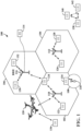
- FIG. 1 two high-power base stations 110 and 112 are shown in cells 102 and 104; and a third high-power base station 114 is shown controlling a remote radio head (RRH) 116 in cell 106.
- the cells 102, 104, and 106 may be referred to as macrocells, as the high-power base stations 110, 112, and 114 support cells having a large size.
- a low-power base station 118 is shown in the small cell 108 (e.g., a microcell, picocell, femtocell, home base station, home Node B, home eNode B, etc.) which may overlap with one or more macrocells.
- the cell 108 may be referred to as a small cell, as the low-power base station 118 supports a cell having a relatively small size.
- Cell sizing can be done according to system design as well as component constraints.
- the access network 100 may include any number of wireless base stations and cells.
- the base stations 110, 112, 114, 118 provide wireless access points to a core network for any number of mobile apparatuses.
- the base stations may be interconnected to one another and/or to one or more other base stations or network nodes (not shown) in the access network 100 through various types of backhaul interfaces such as a direct physical connection, a virtual network, or the like using any suitable transport network.
- the quadcopter 120 may be configured to function as a UE.
- the quadcopter 120 may operate within cell 102 by communicating with base station 110.
- a UE may monitor various parameters of the signal from its serving cell as well as various parameters of neighboring cells. Further, depending on the quality of these parameters, the UE may maintain communication with one or more of the neighboring cells. During this time, if the UE moves from one cell to another, or if signal quality from a neighboring cell exceeds that from the serving cell for a given amount of time, the UE may undertake a handoff or handover from the serving cell to the neighboring (target) cell. For example, UE 124 may move from the geographic area corresponding to its serving cell 102 to the geographic area corresponding to a neighbor cell 106.
- the UE 124 may transmit a reporting message to its serving base station 110 indicating this condition. In response, the UE 124 may receive a handover command, and the UE may undergo a handover to the cell 106.
- a scheduling entity e.g., a base station
- the scheduling entity may be responsible for scheduling, assigning, reconfiguring, and releasing resources for one or more subordinate entities. That is, for scheduled communication, subordinate entities utilize resources allocated by the scheduling entity.
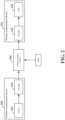
- Block codes, or error correcting codes are frequently used to provide reliable transmission of digital messages over such noisy channels.
- a typical block code an information message or sequence is split up into blocks, each block having a length of K bits.
- An encoder 224 at the first (transmitting) wireless communication device 202 then mathematically adds redundancy to the information message, resulting in codewords having a length of N, where N > K.
- the selection of which bits to puncture (the puncturing pattern) is an important concern and can affect the efficiency of the algorithm. Even if it is possible, it is not desirable to perform an exhaustive search of all puncture patterns to find the optimal puncture pattern, due to the extensive computation complexity that would be required.
- the decoder is to treat the punctured bits.
- the punctured bits may be considered to be unknown bits. That is, the decoder may set the log-likelihood ratio (LLR) for the punctured bits to zero, indicating that the punctured bits are unknown.
- LLR log-likelihood ratio
- the LLR represents the probability of correctly decoding the bit and generally ranges from zero to one, with increasing probability as the LLR approaches one.
- a puncturing scheme generally provides better performance than known-bit puncturing when utilizing lower coding rates (e.g., when the coding rate R is less than 1 ⁇ 2).
- the punctured bits as known bits generally provides better performance than unknown-bit puncturing when utilizing high coding rates (e.g., when the coding rate R is higher than 1 ⁇ 2).
- the performance of the encoder may additionally depend on other factors or parameters, such as the signal to noise ratio (SNR) experienced on the communication channel.
- SNR signal to noise ratio
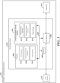
- the processor 304 is responsible for managing the bus 302 and general processing, including the execution of software stored on the computer-readable medium 306.
- the software when executed by the processor 304, causes the processing system 314 to perform the various functions described below for any particular apparatus.
- the computer-readable medium 306 may also be used for storing data that is manipulated by the processor 304 when executing software.
- One or more processors 304 in the processing system may execute software.
- Software shall be construed broadly to mean instructions, instruction sets, code, code segments, program code, programs, subprograms, software modules, applications, software applications, software packages, routines, subroutines, objects, executables, threads of execution, procedures, functions, etc., whether referred to as software, firmware, middleware, microcode, hardware description language, or otherwise.
- the software may reside on a computer-readable medium 306.
- the computer-readable medium 306 may be a non-transitory computer-readable medium.
- the computer-readable medium may also include, by way of example, a carrier wave, a transmission line, and any other suitable medium for transmitting software and/or instructions that may be accessed and read by a computer.
- the computer-readable medium 306 may reside in the processing system 314, external to the processing system 314, or distributed across multiple entities including the processing system 314.
- the computer-readable medium 306 may be embodied in a computer program product.
- a computer program product may include a computer-readable medium in packaging materials.
- the basic matrix F may be represented as 1 0 1 1 .
- the matrix F ⁇ n is generated by raising the basic 2x2 matrix F by the n th Kronecker power.
- This matrix is a lower triangular matrix, in that all the entries above the main diagonal are zero.
- the information bit vector u may include a number ( N ) of original bits that may be polar coded by the generating matrix G N to produce a corresponding number ( N ) of coded bits in the polar codeword c.
- the information bit vector u may include a number of information bits, denoted K , and a number of frozen bits, denoted .
- Frozen bits are bits that are fixed as 0 or 1.
- the value of the frozen bits may generally be known at both the transmitting device and the receiving device.
- the polar encoder 341 may determine the number of information bits and the number of frozen bits based on the coding rate R.
- the remaining ( N - K ) bits in the information block may then be fixed as frozen bits .
- the polar encoder 341 may further analyze the wireless channel over which the polar codeword may be sent. For example, the wireless channel for transmitting the polar codeword may be divided into a set of sub-channels, such that each encoded bit in the polar codeword is transmitted over one of the sub-channels. Thus, each sub-channel may correspond to a particular coded bit location in the polar codeword (e.g., sub-channel-1 may correspond to coded bit location containing coded bit c 1 ). The polar encoder 341 may identify the K best sub-channels for transmitting the information bits and determine the original bit locations in the information block contributing to (or corresponding to) the K best sub-channels.
- the polar encoder 341 may determine K original bit locations in the information block corresponding to the K best sub-channels, designate the K original bit locations for information bits and designate the remaining original bit locations in the information block for fixed bits.
- the polar encoder 341 may sort the sub-channels and select the K best sub-channels (e.g., "good” sub-channels) to transmit the information bits. The polar encoder 341 may then set the original bit locations of the information block corresponding to the K best sub-channels as including information bits and the remaining original bit locations corresponding to the N-K sub-channels (e.g., "bad" sub-channels) as including frozen bits.
- K best sub-channels e.g., "good” sub-channels
- the coded bit at the corresponding coded bit location in the polar codeword may be punctured (removed), whereas if the value is 1, the coded bit at that coded bit location may be kept.
- the polar encoder 341 may further be configured to utilize either an unknown-bit puncturing scheme or a known-bit puncturing scheme with the same puncturing pattern.
- an unknown-bit puncturing scheme the values of the punctured coded bits are unknown at the decoder, and therefore, the decoder may initialize the corresponding LLRs of the punctured bits to zero.
- a known-bit puncturing scheme the values of the punctured coded bits are known, and therefore, the decoder may initialize the corresponding LLRs of the punctured bits to infinity.
- the polar encoder 341 may select the locations of the information bits and frozen bits based on the calculated LLRs, as described above. However, with a known puncturing scheme, the polar encoder 341 may further be configured to select the information bit locations and frozen bit locations in the information block based on not only the LLRs (or BEPs), but also on the puncturing pattern, to ensure that the values of the punctured bits are "known" to the receiver. For example, the polar encoder 341 may select the locations of the frozen bits such that the punctured bits are generated from only the frozen bits, and therefore, their values can be known to the receiver.
- the process may be repeated by removing the remaining last column and last row. This applies to each removed column: when removed, the corresponding bottom row may also removed. This implies that the last N-M columns and rows may be removed to effect puncturing of the coded bits that would have been generated from the last N-M frozen bits. Because the puncture starts from the last column of the matrix and continues to the left one by one (e.g., based on the number of punctured bits), the value of the punctured bits will be known with values of zeros as long as the last N-M original bits of the information block are set as frozen bits with values of zeros.
- the punctured codeword may be generated by modifying the generating matrix, as described above, this type of puncturing (e.g., puncturing as part of the polar coding) is typically more complex than performing puncturing after generation of the polar codeword. Therefore, the puncturing schemes discussed below assume that puncturing is performed after the generation of the polar codeword.
- the processor 304 may further include puncturing scheme selection circuitry 342, which may in some examples operate in coordination with puncturing scheme selection software 342 stored in the computer-readable medium 306.
- the puncturing scheme selection software 342 may be configured to select between the unknown-bit puncturing scheme and the known-bit puncturing scheme and provide the selected puncturing scheme to the polar encoder 342 for use in polar coding and puncturing.
- the puncturing scheme selection circuitry 342 may calculate a respective LLR sum for each of the unknown-bit puncturing scheme and the known bit puncturing scheme and select the puncturing scheme with the greatest LLR sum. For example, the puncturing scheme selection circuitry 342 may calculate the LLR sum for the unknown-bit puncturing scheme by considering the coded bit locations corresponding to the final punctured bit locations as including unknown bits and setting the unknown-bit LLRs of each of those unknown bit locations to 0. The LLR sum for the unknown-bit puncturing scheme may then be computed by performing density evolution or Gaussian approximation, as described above, to calculate the original bit location LLRs and determining the sum of the calculated original bit location LLRs.
- the processor 304 may include a polar decoder 343, which may in some examples operate in coordination with polar decoding software 353 stored in the computer-readable medium 306.
- the polar decoder 343 may be configured to receive a punctured polar codeword and decode the punctured polar codeword to produce the original information block.
- the polar decoder 343 may perform successive cancellation (SC) polar decoding or SC polar list decoding to decode the punctured polar codeword.
- SC successive cancellation
- the polar decoder 343 may determining whether the punctured bits in the punctured polar codeword are considered known bits or unknown bits. If the punctured bits are considered unknown bits, the polar decoder 343 may set the LLR of each of the punctured bits to zero. However, if the punctured bits are considered known bits, the polar decoder 343 may set the LLR of each of the punctured bits to infinity.
- the polar codeword 430 is received by a puncture block 440.
- L ( N-M )
- a punctured codeword 450 including L coded bit locations 455, each including one of the non-punctured coded bits ( c 1 , c 2 , ..., c L ) .
- the polar encoder 420 and puncture block 440 may, in some examples, correspond to the polar encoder 341 and polar encoding software 351 shown and described above in connection with FIG. 3 .
- FIG. 5 An example operation of the puncture block 440 is shown in FIG. 5 .
- an initial puncturing pattern 500 is generated including a plurality pattern bit locations 505.
- Each of the pattern bit locations 505 corresponds to one of the coded bit locations 435 of the polar codeword 430 generated by the polar encoder 420 shown in FIG. 4 .
- the value of each pattern bit location 505 determines whether a coded bit at a corresponding coded bit location 435 in the polar codeword 430 is punctured or kept.
- bit-reversal permutation may also be performed on the initial puncturing pattern 500 to produce a final puncturing pattern 510 that is similar to a uniform puncturing pattern.
- the final puncturing pattern 510 includes the same number of pattern bit locations 515 as the initial puncture pattern 500, but as shown in FIG. 5 , the punctured bit locations may be different in the final puncturing pattern 510 than in the initial puncturing pattern 500 based on the bit-reversal permutation applied.
- the final puncturing pattern 510 may then be applied to the polar codeword 430 and function as a mask, puncturing N-M coded bits of the polar codeword 430 to produce the punctured polar codeword 450 having a codeword length of L.
- coded bits c 2 and c N- 1 are illustrated as being punctured, for simplicity.
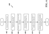
- FIG. 6 is a flow chart illustrating an exemplary process 600 for polar coding according to the present invention.
- the process 600 may be implemented by a wireless communication device as described above and illustrated in FIGs. 1-3 .
- the process 600 may be implemented by any suitable means for carrying out the described functions.
- the wireless communication device generates a puncturing pattern.
- the puncture pattern P u is represented by a vector with all elements having a value of 1 except for the last N-M elements, which have a value of 0.
- N is the codeword length
- ( N-M ) is the desired block length after puncturing.
- the wireless communication device also performs bit-reversal permutation on the initial puncturing pattern to produce a final puncturing pattern P.
- the polar encoder 341 shown and described above in connection with FIG. 3 and/or the puncture block 440 shown and described above in connection with FIGs. 4 and 5 may generate the puncturing pattern.
- the wireless communication device compares the first LLR sum with the second LLR sum, and selects the puncturing scheme corresponding to the larger sum.
- the puncturing scheme selection circuitry 342 shown and described above in connection with FIG. 3 may select the puncturing scheme.
- FIG. 7 is a flow chart illustrating an exemplary process 700 for calculating the first LLR sum for an unknown-bit puncturing scheme according to the invention.
- the process 700 may be implemented by a wireless communication device as described above and illustrated in FIGs. 1-3 .
- the process 700 may be implemented by any suitable means for carrying out the described functions.
- the wireless communication device sets the initial LLRs of the punctured coded bit locations to zero.
- the wireless communication device determines the LLRs of the remaining coded bit locations (e.g., based on sub-channel conditions). For example, the puncturing scheme selection circuitry 342 shown and described above in connection with FIG. 3 may set the LLR's of the punctured coded bit locations to zero and determine the LLRs of the remaining bit locations.
- the wireless communication device calculates the LLRs of the original bit locations of the information block by performing density evolution or Gaussian approximation.
- the wireless communication device then calculates the first LLR sum for the unknown-bit puncturing scheme from the original bit location LLRs.
- the puncturing scheme selection circuitry 342 shown and described above in connection with FIG. 3 may calculate the original bit location LLRs and calculate the first LLR sum from the calculated original bit location LLRs.
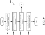
- FIG. 9 is a flow chart illustrating an exemplary process 900 for calculating the first LLR sum for a known-bit puncturing scheme according to the invention.
- the process 900 may be implemented by a wireless communication device as described above and illustrated in FIGs. 1-3 .
- the process 900 may be implemented by any suitable means for carrying out the described functions.
- the wireless communication device sets the initial LLRs of the punctured coded bit locations to infinity.
- the wireless communication device determines the LLRs of the remaining coded bit locations (e.g., based on sub-channel conditions). For example, the puncturing scheme selection circuitry 342 shown and described above in connection with FIG. 3 may set the LLR's of the punctured coded bit locations to infinity and determine the LLRs of the remaining bit locations.
- the wireless communication device calculates the LLRs of the original bit locations of the information block by performing density evolution or Gaussian approximation.
- the wireless communication device then calculates the first LLR sum for the unknown-bit puncturing scheme from the original bit location LLRs.
- the puncturing scheme selection circuitry 342 shown and described above in connection with FIG. 3 may calculate the original bit location LLRs and calculate the first LLR sum from the calculated original bit location LLRs.
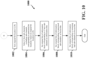
- the process may proceed as indicated by node B to FIG. 10 , which illustrates an exemplary process 1000 for determining the locations of the information bits and frozen bits in the information block.
- the process 1000 may be implemented by a wireless communication device as described above and illustrated in FIGs. 1-3 .
- the process 1000 may be implemented by any suitable means for carrying out the described functions.
- the wireless communication device may set the original bits of the information block corresponding to the K best sub-channels ("good" sub-channels) as information bits.
- the wireless communication device may set the original bits of the information block corresponding to the sub-channels that correspond to the punctured bit locations as frozen bits.
- the wireless communication device may set the original bits of the information block corresponding to the remaining "bad" sub-channels (e.g., the remaining number of sub-channels equal to the difference between N-K and N-M sub-channels) as frozen bits.
- the wireless communication device may fix the frozen bits to the same value (e.g., 1 or 0).
- the polar encoder 341 shown and described above in connection with FIG. 3 and/or the polar encoder 420 shown and described above in connection with FIG. 4 may set the original bits of the information block as information bits or frozen bits.
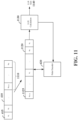
- an initial information block is an N -bit information block 410 including N initial bit locations 415, each containing a respective original bit ( u 1 , u 2 , ..., u N-M , U N ) .
- a bit-reversal permutation may then be applied to the information block 410 to produce a bit-reversed information block 1120 including N original bit locations 1125 corresponding to the N initial bit locations 415 in the initial information block 410.
- the bit-reversal permutation effectively re-orders the original bits of the information block 410.
- the original bit u 2 may be in a second initial bit location 415 in the information block 410 and in the last original bit location 1125 of the bit-reversed information block 1120.
- the bit-reversed information block 1120 may then be provided to an LLR calculation block 1130 to calculate the individual LLRs of each of the original bit locations 1125 and the LLR sums for each of the puncturing schemes.
- the LLR calculation block 1130 may be implemented, for example, in the polar encoder 341 or 410 shown and described above in connection with FIGs. 3 and 4 and/or the puncturing scheme selection circuitry 342 shown and described above in connection with FIG. 3 .
- the LLR calculation block 1130 may perform density evolution or Gaussian approximation to determine the individual LLRs for each of the original bit locations 1125 based on the LLR values of the corresponding coded bit locations (not shown).
- the LLR calculation block 1130 may provide the individual calculated original bit location LLRs to the polar encoder 420 to set each of the original bits in the bit-reversed information block 1120 as an information bit or a frozen bit, as described above.
- the last N-M original bits 1110 of the initial information block 410 corresponding to the punctured bit locations may be set as frozen bits with values of zeros.
- the frozen bits may be in different original bit locations 1125, as shown in FIG. 11 .
- a process 1200 is illustrated for polar decoding according to some aspects of the disclosure.
- the process 1200 may be implemented by a wireless communication device as described above and illustrated in FIGs. 1-3 .
- the process 1200 may be implemented by any suitable means for carrying out the described functions.
- the wireless communication device may determine whether punctured bits in the received polar codeword are to be treated as known bits or unknown bits.
- this determination may be explicit or implicit.
- an explicit transmission may be made from the transmitting device to the receiving device, informing the decoder in the receiving device of which puncturing method is used. Any suitable transmission may be utilized for the explicit indication, e.g., being as simple as a single bit, with one value indicating that the punctured bits are to be treated as known bits, an another value indicating that the punctured bits are to be treated as unknown bits.
- the decoder may deduce that known bit puncturing is used; and if the coding rate R is not greater than the threshold, then the decoder may deduce that unknown bit puncturing is used.
- a threshold e.g. 1 ⁇ 2
- the decoder may deduce that unknown bit puncturing is used.
- the polar decoder 343 shown and described above in connection with FIG. 3 may determine whether the punctured bits are known bits or unknown bits.
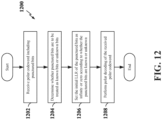
- FIG. 13 is a flow chart illustrating an exemplary process 1300 for setting the initial LLRs of punctured bits of a received polar codeword according to some aspects of the present disclosure.
- the process 1200 may be implemented by a wireless communication device as described above and illustrated in FIGs. 1-3 .
- the process 1200 may be implemented by any suitable means for carrying out the described functions.
- the wireless communication device may receive a polar codeword including one or more punctured bits.
- the wireless communication device may receive a punctured polar codeword, and with knowledge of the puncturing pattern, identify the locations of the punctured bits in the polar codeword.
- the polar decoder 343 shown and described above in connection with FIG. 3 may receive the polar codeword and determine the locations of the punctured bits.
- the wireless communication device may determine whether an explicit indication of the puncturing scheme utilized by the transmitter was received. If an explicit indication was received (Y branch of 1304), at block 1306, the wireless communication device may set the initial LLRs of the punctured bits based on the explicit indication. For example, the wireless communication device may set the initial LLRs of the punctured bits to zero if the unknown-bit puncturing scheme was used and to infinity if the known-bit puncturing scheme was used. For example, the polar decoder 343 shown and described above in connection with FIG. 3 may determine whether an explicit instruction was received, and if so, set the initial LLRs of the punctured bits accordingly.
- circuit and circuitry are used broadly, and intended to include both hardware implementations of electrical devices and conductors that, when connected and configured, enable the performance of the functions described in the present disclosure, without limitation as to the type of electronic circuits, as well as software implementations of information and instructions that, when executed by a processor, enable the performance of the functions described in the present disclosure.
Landscapes
- Engineering & Computer Science (AREA)
- Physics & Mathematics (AREA)
- Probability & Statistics with Applications (AREA)
- Theoretical Computer Science (AREA)
- Computer Networks & Wireless Communication (AREA)
- Signal Processing (AREA)
- Artificial Intelligence (AREA)
- Mobile Radio Communication Systems (AREA)
- Error Detection And Correction (AREA)
- Dc Digital Transmission (AREA)
Claims (10)
- Verfahren zum Polarcodieren eines Informationsblocks, das Verfahren umfassend:Erzeugen (602) eines anfänglichen Punktierungsmusters, das eine Vielzahl von punktierten Bitpositionen zum Punktieren entsprechender codierter Bitpositionen in einem Polarcodewort (430) umfasst;Berechnen (604) einer ersten Log-Likelihood-Ratio-, LLR-, Summe für ein Punktierungsschema unbekannter Bits durch Betrachten der codierten Bitpositionen, die den punktierten Bitpositionen entsprechen, als würden sie unbekannte Bits umfassen, wobei das Berechnen der ersten LLR-Summe umfasst:Setzen eines jeweiligen LLR unbekannter Bits für jede codierte Bitposition, die einer der punktierten Bitpositionen entspricht, auf null;Bestimmen eines jeweiligen LLR erster codierter Bits für verbleibende der codierten Bitpositionen basierend auf Unterkanalbedingungen;Berechnen jeweiliger erster LLRs für jede ursprüngliche Bitposition des Informationsblocks aus den jeweiligen LLRs erster codierter Bits und den jeweiligen LLRs unbekannter Bits durch Durchführen von Dichteevolution oder Gauß'scher Näherung; undBerechnen der ersten LLR-Summe basierend auf den ersten LLRs;Berechnen (606) einer zweiten LLR-Summe für ein Punktierungsschema bekannter Bits durch Betrachten der codierten Bitpositionen, die den punktierten Bitpositionen entsprechen, als würden sie bekannte Bits umfassen, wobei das Berechnen der zweiten LLR-Summe umfasst:Setzen eines jeweiligen LLR bekannter Bits für jede codierte Bitposition, die einer der punktierten Bitpositionen entspricht, auf unendlich;Bestimmen eines jeweiligen LLR zweiter codierter Bits für verbleibende der codierten Bitpositionen basierend auf Unterkanalbedingungen;Berechnen jeweiliger zweiter LLRs für jede ursprüngliche Bitposition des Informationsblocks aus den jeweiligen LLRs zweiter codierter Bits und den jeweiligen LLRs bekannter Bits durch Durchführen von Dichteevolution oder Gauß'scher Näherung; undBerechnen der zweiten LLR-Summe basierend auf den zweiten LLRs;Auswählen (608) des Punktierungsschemas unbekannter Bits, wenn die erste LLR-Summe größer als die zweite LLR-Summe ist, und Auswählen (608) des Punktierungsschemas bekannter Bits, wenn die zweite LLR-Summe größer als die erste LLR-Summe ist;Polarcodieren (610) des Informationsblocks, um das Polarcodewort (430) zu erzeugen; undPunktieren (612) des Polarcodeworts (430) unter Verwendung eines endgültigen Punktierungsmusters und basierend auf einem ausgewählten Punktierungsschema, um ein punktiertes Codewort zu erzeugen, das eine andere Codewortlänge als eine Zweierpotenz umfasst, wobei das endgültige Punktierungsmuster auf Bitumkehrpermutation am anfänglichen Punktierungsmuster basiert und endgültige punktierte Bitpositionen umfasst, die sich von den punktierten Bitpositionen unterscheiden.
- Verfahren nach Anspruch 1, wobei das endgültige Punktierungsmuster ein einheitliches Punktierungsmuster umfasst.
- Verfahren nach Anspruch 1, wobei jede der codierten Bitpositionen einem Unterkanal entspricht und das Polarcodewort (430) eine ursprüngliche Codewortlänge von N umfasst, und ferner umfassend:Sortieren der Unterkanäle basierend auf den ersten LLRs;Auswählen von Kbesten Unterkanälen gemäß den ersten LLRs;Setzen ursprünglicher Bits des Informationsblocks, die den K besten Unterkanälen entsprechen, als Informationsbits; undSetzen ursprünglicher Bits des Informationsblocks, die N-K Unterkanälen entsprechen, als eingefrorene Bits.
- Verfahren nach Anspruch 1, wobei jede der codierten Bitpositionen einem Unterkanal entspricht, das Polarcodewort eine ursprüngliche Codewortlänge von N umfasst und das punktierte Codewort die Codewortlänge von M umfasst, und ferner umfassend:Sortieren der Unterkanäle basierend auf den zweiten LLRs;Auswählen von K besten Unterkanälen, ausschließlich der Unterkanäle, die den punktierten Bitpositionen entsprechen, gemäß den zweiten LLRs;Setzen ursprünglicher Bits des Informationsblocks, die den K besten Unterkanälen entsprechen, als Informationsbits;Setzen ursprünglicher Bits des Informationsblocks, die den Unterkanälen entsprechen, die den punktierten Bitpositionen entsprechen, als eingefrorene Bits; undSetzen ursprünglicher Bits des Informationsblocks, die einer verbleibenden Anzahl von Unterkanälen entsprechen, als eingefrorene Bits, wobei die verbleibende Anzahl von Unterkanälen gleich einer Differenz zwischen N-K und N-M Unterkanälen ist.
- Verfahren nach Anspruch 1, ferner umfassend:Übertragen einer expliziten Angabe des ausgewählten Punktierungsschemas; undÜbertragen des punktierten Polarcodeworts.
- Verfahren nach Anspruch 1, wobei das Erzeugen des anfänglichen Punktierungsmusters ferner umfasst:
Erzeugen des anfänglichen Punktierungsmusters mit der Vielzahl von punktierten Bitpositionen an einem Ende des anfänglichen Punktierungsmusters. - Verfahren nach Anspruch 6, wobei das Polarcodewort eine ursprüngliche Codewortlänge von N umfasst und das punktierte Codewort die Codewortlänge von M umfasst, und ferner umfassend:
Setzen eines letzten N-M ursprünglichen Bits des Informationsblocks auf null. - Vorrichtung (300), die zum Polarcodieren konfiguriert ist, die Vorrichtung (300) umfassend:Mittel zum Erzeugen eines anfänglichen Punktierungsmusters, das eine Vielzahl von punktierten Bitpositionen zum Punktieren entsprechender codierter Bitpositionen in einem Polarcodewort (430) umfasst;Mittel zum Berechnen einer ersten Log-Likelihood-Ratio-, LLR-, Summe für ein Punktierungsschema unbekannter Bits durch Betrachten der codierten Bitpositionen, die den punktierten Bitpositionen entsprechen, als würden sie unbekannte Bits umfassen, wobei das Berechnen der ersten LLR-Summe umfasst:Setzen eines jeweiligen LLR unbekannter Bits für jede codierte Bitposition, die einer der punktierten Bitpositionen entspricht, auf null;Bestimmen eines jeweiligen LLR erster codierter Bits für verbleibende der codierten Bitpositionen basierend auf Unterkanalbedingungen;Berechnen jeweiliger erster LLRs für jede ursprüngliche Bitposition des Informationsblocks aus den jeweiligen LLRs erster codierter Bits und den jeweiligen LLRs unbekannter Bits durch Durchführen von Dichteevolution oder Gauß'scher Näherung; undBerechnen der ersten LLR-Summe basierend auf den ersten LLRs;Mittel zum Berechnen einer zweiten LLR-Summe für ein Punktierungsschema bekannter Bits durch Betrachten der codierten Bitpositionen, die den punktierten Bitpositionen entsprechen, als würden sie bekannte Bits umfassen, wobei das Berechnen der zweiten LLR-Summe umfasst:Setzen eines jeweiligen LLR bekannter Bits für jede codierte Bitposition, die einer der punktierten Bitpositionen entspricht, auf unendlich;Bestimmen eines jeweiligen LLR zweiter codierter Bits für verbleibende der codierten Bitpositionen basierend auf Unterkanalbedingungen;Berechnen jeweiliger zweiter LLRs für jede ursprüngliche Bitposition des Informationsblocks aus den jeweiligen LLRs zweiter codierter Bits und den jeweiligen LLRs bekannter Bits durch Durchführen von Dichteevolution oder Gauß'scher Näherung; undBerechnen der zweiten LLR-Summe basierend auf den zweiten LLRs;Mittel zum Auswählen des Punktierungsschemas unbekannter Bits, wenn die erste LLR-Summe größer als die zweite LLR-Summe ist, und Auswählen (608) des Punktierungsschemas bekannter Bits, wenn die zweite LLR-Summe größer als die erste LLR-Summe ist;Mittel zum Polarcodieren des Informationsblocks, um das Polarcodewort (430) zu erzeugen; undMittel zum Punktieren des Polarcodeworts (430) unter Verwendung eines endgültigen Punktierungsmusters und basierend auf einem ausgewählten Punktierungsschema, um ein punktiertes Codewort zu erzeugen, das eine andere Codewortlänge als eine Zweierpotenz umfasst, wobei das endgültige Punktierungsmuster auf Bitumkehrpermutation am anfänglichen Punktierungsmuster basiert und endgültige punktierte Bitpositionen umfasst, die sich von den punktierten Bitpositionen unterscheiden.
- Vorrichtung (300) nach Anspruch 8, die Vorrichtung (300) ferner umfassend Mittel zum Durchführen der Schritte des Verfahrens nach einem der Ansprüche 2 bis 7.
- Computerprogramm, umfassend Anweisungen, die, wenn das Programm von einem Computer ausgeführt wird, den Computer veranlassen, die Schritte des Verfahrens nach einem der Ansprüche 1 bis 7 auszuführen.
Priority Applications (1)
| Application Number | Priority Date | Filing Date | Title |
|---|---|---|---|
| EP24215056.3A EP4489315A3 (de) | 2016-01-25 | 2016-08-17 | Erzeugung von polaren codes mit variabler blocklänge mittels punktierung |
Applications Claiming Priority (2)
| Application Number | Priority Date | Filing Date | Title |
|---|---|---|---|
| PCT/CN2016/071959 WO2017127973A1 (en) | 2016-01-25 | 2016-01-25 | Generation of polar codes with a variable block length utilizing puncturing |
| PCT/CN2016/095661 WO2017128700A1 (en) | 2016-01-25 | 2016-08-17 | Generation of polar codes with a variable block length utilizing puncturing |
Related Child Applications (2)
| Application Number | Title | Priority Date | Filing Date |
|---|---|---|---|
| EP24215056.3A Division EP4489315A3 (de) | 2016-01-25 | 2016-08-17 | Erzeugung von polaren codes mit variabler blocklänge mittels punktierung |
| EP24215056.3A Division-Into EP4489315A3 (de) | 2016-01-25 | 2016-08-17 | Erzeugung von polaren codes mit variabler blocklänge mittels punktierung |
Publications (4)
| Publication Number | Publication Date |
|---|---|
| EP3408940A1 EP3408940A1 (de) | 2018-12-05 |
| EP3408940A4 EP3408940A4 (de) | 2019-08-14 |
| EP3408940C0 EP3408940C0 (de) | 2025-04-16 |
| EP3408940B1 true EP3408940B1 (de) | 2025-04-16 |
Family
ID=59397081
Family Applications (2)
| Application Number | Title | Priority Date | Filing Date |
|---|---|---|---|
| EP24215056.3A Pending EP4489315A3 (de) | 2016-01-25 | 2016-08-17 | Erzeugung von polaren codes mit variabler blocklänge mittels punktierung |
| EP16887577.1A Active EP3408940B1 (de) | 2016-01-25 | 2016-08-17 | Erzeugung von polar codes mit variabler blocklänge unter verwendung von punktierung |
Family Applications Before (1)
| Application Number | Title | Priority Date | Filing Date |
|---|---|---|---|
| EP24215056.3A Pending EP4489315A3 (de) | 2016-01-25 | 2016-08-17 | Erzeugung von polaren codes mit variabler blocklänge mittels punktierung |
Country Status (8)
| Country | Link |
|---|---|
| US (2) | US10749633B2 (de) |
| EP (2) | EP4489315A3 (de) |
| CN (1) | CN108604903B (de) |
| AU (1) | AU2016388920B2 (de) |
| BR (1) | BR112018014973A2 (de) |
| CA (1) | CA3009570C (de) |
| SG (1) | SG11201805161XA (de) |
| WO (2) | WO2017127973A1 (de) |
Families Citing this family (25)
| Publication number | Priority date | Publication date | Assignee | Title |
|---|---|---|---|---|
| WO2017127973A1 (en) | 2016-01-25 | 2017-08-03 | Qualcomm Incorporated | Generation of polar codes with a variable block length utilizing puncturing |
| JP6599294B2 (ja) * | 2016-09-20 | 2019-10-30 | 株式会社東芝 | 異常検知装置、学習装置、異常検知方法、学習方法、異常検知プログラム、および学習プログラム |
| EP3520223B1 (de) * | 2016-09-30 | 2023-06-14 | Telefonaktiebolaget LM Ericsson (PUBL) | Räumlich gekoppelte polarcodes |
| WO2018106001A1 (ko) * | 2016-12-06 | 2018-06-14 | 엘지전자 주식회사 | 폴라 코드를 이용한 제어 정보 전송 방법 및 장치 |
| US10735154B2 (en) * | 2017-03-23 | 2020-08-04 | Huawei Technologies Co., Ltd. | Methods and apparatus for coding sub-channel selection |
| CN108809500B (zh) * | 2017-05-05 | 2020-12-22 | 华为技术有限公司 | 编码方法、装置和设备 |
| US20180331697A1 (en) * | 2017-05-15 | 2018-11-15 | Qualcomm Incorporated | Nominal complexity and weighted combinations for polar code construction |
| WO2019030908A1 (en) * | 2017-08-10 | 2019-02-14 | Nec Corporation | ADAPTATION OF FLOW IN POLAR CODES |
| WO2019047246A1 (en) | 2017-09-11 | 2019-03-14 | Huawei Technologies Co., Ltd. | METHODS AND APPARATUS FOR POLAR CODING |
| CN118353576A (zh) | 2017-10-01 | 2024-07-16 | 大唐移动通信设备有限公司 | 一种极化编码方法、装置、电子设备及存储介质 |
| WO2019062521A1 (zh) * | 2017-10-01 | 2019-04-04 | 电信科学技术研究院有限公司 | 一种极化编码方法、装置、电子设备及存储介质 |
| KR102426047B1 (ko) * | 2017-11-06 | 2022-07-26 | 삼성전자주식회사 | 폴라 부호 복호화 장치 및 방법 |
| TW201924294A (zh) * | 2017-11-16 | 2019-06-16 | 財團法人資訊工業策進會 | 基於正交分頻多工的基頻處理裝置與基頻處理方法 |
| KR102031098B1 (ko) * | 2017-11-16 | 2019-10-11 | 엘지전자 주식회사 | Pbch 전송 방법 및 전송 장치, 및 pbch 수신 방법 및 수신 장치 |
| WO2019095267A1 (en) * | 2017-11-17 | 2019-05-23 | Qualcomm Incorporated | Polar coding techniques for blind detection of different payload sizes |
| CN110034851B (zh) * | 2018-01-12 | 2020-12-01 | 华为技术有限公司 | 编码方法、编码设备以及系统 |
| US10812107B2 (en) * | 2018-01-19 | 2020-10-20 | Huawei Technologies Co., Ltd. | Apparatus and methods for polar code construction and bit position allocation |
| US10608669B2 (en) | 2018-02-16 | 2020-03-31 | At&T Intellectual Property I, L.P. | Performance of data channel using polar codes for a wireless communication system |
| CN108462560A (zh) * | 2018-03-26 | 2018-08-28 | 西安电子科技大学 | 一种用于极化码级联的编译码方法 |
| WO2019191923A1 (en) * | 2018-04-04 | 2019-10-10 | Qualcomm Incorporated | Techniques and apparatuses for codeword bit selection for rate-compatible polar coding |
| CN108809329B (zh) * | 2018-05-03 | 2021-09-28 | 东南大学 | 一种能同时处理极化码和ldpc码的bp译码器的配置方法 |
| US11513897B2 (en) * | 2020-12-28 | 2022-11-29 | Samsung Electronics Co., Ltd. | Error correction on length-compatible polar codes for memory systems |
| CN115085740A (zh) * | 2021-03-16 | 2022-09-20 | 华为技术有限公司 | 一种编码和译码方法及装置 |
| US11799700B1 (en) * | 2022-08-31 | 2023-10-24 | Qualcomm Incorporated | Decoding multi-level coded (MLC) systems |
| EP4648316A1 (de) * | 2023-01-02 | 2025-11-12 | LG Electronics Inc. | Verfahren, kommunikationsvorrichtung, verarbeitungsvorrichtung und speichermedium zur durchführung von codierung sowie verfahren und kommunikationsvorrichtung zur durchführung von decodierung |
Family Cites Families (25)
| Publication number | Priority date | Publication date | Assignee | Title |
|---|---|---|---|---|
| KR20050118056A (ko) * | 2004-05-12 | 2005-12-15 | 삼성전자주식회사 | 다양한 부호율을 갖는 Block LDPC 부호를 이용한이동 통신 시스템에서의 채널부호화 복호화 방법 및 장치 |
| US7596354B2 (en) | 2005-12-12 | 2009-09-29 | Qualcomm, Inc. | Optimizing polarization of forward link |
| US8000411B2 (en) * | 2008-01-04 | 2011-08-16 | Qualcomm Incorporated | Decoding scheme using multiple hypotheses about transmitted messages |
| CN102122966B (zh) * | 2011-04-15 | 2012-11-14 | 北京邮电大学 | 基于信道极化的交错结构重复码的编码器及其编译码方法 |
| US9264073B2 (en) * | 2011-09-02 | 2016-02-16 | Samsung Electronics Co., Ltd | Freezing-based LDPC decoder and method |
| CN103220001B (zh) * | 2012-01-20 | 2016-09-07 | 华为技术有限公司 | 与循环冗余校验级联的极性码的译码方法和译码装置 |
| US9954643B2 (en) * | 2012-06-22 | 2018-04-24 | Samsung Electronics Co., Ltd. | Communication system with repeat-response combining mechanism and method of operation thereof |
| KR102015121B1 (ko) * | 2012-10-17 | 2019-08-28 | 삼성전자주식회사 | 불휘발성 메모리 장치를 제어하도록 구성되는 컨트롤러 및 컨트롤러의 동작 방법 |
| CN103023618B (zh) * | 2013-01-11 | 2015-04-22 | 北京邮电大学 | 一种任意码长的极化编码方法 |
| CN103281166B (zh) * | 2013-05-15 | 2016-05-25 | 北京邮电大学 | 一种基于极化码的混合自动重传请求传输方法 |
| CN103414540A (zh) * | 2013-08-14 | 2013-11-27 | 南京邮电大学 | 一种基于Polar码的退化窃听信道速率兼容方法 |
| US9007241B2 (en) | 2013-09-16 | 2015-04-14 | Seagate Technology Llc | Reduced polar codes |
| CN103746708A (zh) * | 2013-10-25 | 2014-04-23 | 中国农业大学 | 一种Polar-LDPC级联码的构造方法 |
| WO2015062107A1 (zh) * | 2013-11-04 | 2015-05-07 | 华为技术有限公司 | Polar码的速率匹配方法和设备、无线通信装置 |
| CN105075163B (zh) | 2013-11-20 | 2019-02-05 | 华为技术有限公司 | 极化码的处理方法和设备 |
| CN103873073B (zh) * | 2014-03-20 | 2017-03-15 | 北京遥测技术研究所 | 一种基于并行与加窗结构的Turbo码高速译码实现方法 |
| CN103888151B (zh) | 2014-03-28 | 2017-02-15 | 中山大学 | 一种基于分组马尔可夫叠加编码的多码率码编码方法 |
| WO2016137234A1 (en) * | 2015-02-24 | 2016-09-01 | Samsung Electronics Co., Ltd. | Transmitter and repetition method thereof |
| US10382165B2 (en) * | 2015-03-02 | 2019-08-13 | Samsung Electronics Co., Ltd. | Transmitter and shortening method thereof |
| CN111865499B (zh) * | 2015-03-02 | 2023-07-21 | 三星电子株式会社 | 接收设备和接收方法 |
| WO2016140514A1 (en) * | 2015-03-02 | 2016-09-09 | Samsung Electronics Co., Ltd. | Transmitter and segmentation method thereof |
| CN115642919A (zh) * | 2015-03-02 | 2023-01-24 | 三星电子株式会社 | 发送器及其用于产生附加奇偶校验的方法 |
| US10177787B1 (en) * | 2015-09-17 | 2019-01-08 | Seagate Technology Llc | Mitigation of error correction failure due to trapping sets |
| WO2017127973A1 (en) | 2016-01-25 | 2017-08-03 | Qualcomm Incorporated | Generation of polar codes with a variable block length utilizing puncturing |
| EP3273602B1 (de) * | 2016-07-19 | 2022-01-26 | MediaTek Inc. | Ratenanpassung niedriger komplexität für polare codes |
-
2016
- 2016-01-25 WO PCT/CN2016/071959 patent/WO2017127973A1/en not_active Ceased
- 2016-08-17 BR BR112018014973A patent/BR112018014973A2/pt not_active Application Discontinuation
- 2016-08-17 CA CA3009570A patent/CA3009570C/en active Active
- 2016-08-17 WO PCT/CN2016/095661 patent/WO2017128700A1/en not_active Ceased
- 2016-08-17 SG SG11201805161XA patent/SG11201805161XA/en unknown
- 2016-08-17 EP EP24215056.3A patent/EP4489315A3/de active Pending
- 2016-08-17 CN CN201680079776.4A patent/CN108604903B/zh active Active
- 2016-08-17 AU AU2016388920A patent/AU2016388920B2/en active Active
- 2016-08-17 US US16/065,077 patent/US10749633B2/en active Active
- 2016-08-17 EP EP16887577.1A patent/EP3408940B1/de active Active
-
2020
- 2020-05-14 US US16/874,264 patent/US11309997B2/en active Active
Also Published As
| Publication number | Publication date |
|---|---|
| US11309997B2 (en) | 2022-04-19 |
| SG11201805161XA (en) | 2018-08-30 |
| CN108604903B (zh) | 2021-08-24 |
| EP4489315A2 (de) | 2025-01-08 |
| EP3408940A4 (de) | 2019-08-14 |
| BR112018014973A2 (pt) | 2018-12-11 |
| EP3408940C0 (de) | 2025-04-16 |
| CA3009570A1 (en) | 2017-08-03 |
| US10749633B2 (en) | 2020-08-18 |
| CA3009570C (en) | 2022-03-29 |
| CN108604903A (zh) | 2018-09-28 |
| US20200274644A1 (en) | 2020-08-27 |
| US20180375615A1 (en) | 2018-12-27 |
| EP3408940A1 (de) | 2018-12-05 |
| AU2016388920B2 (en) | 2020-08-20 |
| WO2017128700A1 (en) | 2017-08-03 |
| EP4489315A3 (de) | 2025-04-09 |
| AU2016388920A1 (en) | 2018-07-05 |
| WO2017127973A1 (en) | 2017-08-03 |
Similar Documents
| Publication | Publication Date | Title |
|---|---|---|
| US11309997B2 (en) | Generation of polar codes with a variable block length utilizing puncturing | |
| EP3430748B1 (de) | Übertragung von neuen daten in einer neuübertragung mit hybrider automatischer wiederholungsanforderung (harq) mit polaren codierten übertragungen | |
| US11362769B2 (en) | Hybrid automatic repeat request (HARQ) with polar coded transmissions | |
| RU2749772C2 (ru) | Проектное решение с использованием множества базовых графов на основе контроля по четности малой плотности (ldpc) | |
| EP3563502B1 (de) | Verschachtelte struktur für polarcodekonstruktion unter verwendung von dichteentwicklung | |
| US20180019766A1 (en) | Pipelining for polar code list decoding | |
| US10686556B2 (en) | Robust and universal polar codes | |
| JP7102437B2 (ja) | ポーラーコードのための効率的インターリーバ設計 | |
| US11451245B2 (en) | Efficient interleaver designs for polar codes | |
| WO2019028590A1 (en) | ANTICIPATED STOP OF POLAR CODES USING DISTRIBUTED CYCLIC REDUNDANCY MONITORING | |
| HK40021783A (en) | Interleaving before crc coding a nr pbch payload including known bits to enhance polar code performance |
Legal Events
| Date | Code | Title | Description |
|---|---|---|---|
| STAA | Information on the status of an ep patent application or granted ep patent |
Free format text: STATUS: THE INTERNATIONAL PUBLICATION HAS BEEN MADE |
|
| PUAI | Public reference made under article 153(3) epc to a published international application that has entered the european phase |
Free format text: ORIGINAL CODE: 0009012 |
|
| STAA | Information on the status of an ep patent application or granted ep patent |
Free format text: STATUS: REQUEST FOR EXAMINATION WAS MADE |
|
| 17P | Request for examination filed |
Effective date: 20180807 |
|
| AK | Designated contracting states |
Kind code of ref document: A1 Designated state(s): AL AT BE BG CH CY CZ DE DK EE ES FI FR GB GR HR HU IE IS IT LI LT LU LV MC MK MT NL NO PL PT RO RS SE SI SK SM TR |
|
| AX | Request for extension of the european patent |
Extension state: BA ME |
|
| DAV | Request for validation of the european patent (deleted) | ||
| DAX | Request for extension of the european patent (deleted) | ||
| A4 | Supplementary search report drawn up and despatched |
Effective date: 20190716 |
|
| RIC1 | Information provided on ipc code assigned before grant |
Ipc: H03M 13/13 20060101AFI20190710BHEP Ipc: H04L 1/00 20060101ALI20190710BHEP |
|
| STAA | Information on the status of an ep patent application or granted ep patent |
Free format text: STATUS: EXAMINATION IS IN PROGRESS |
|
| 17Q | First examination report despatched |
Effective date: 20210422 |
|
| GRAP | Despatch of communication of intention to grant a patent |
Free format text: ORIGINAL CODE: EPIDOSNIGR1 |
|
| STAA | Information on the status of an ep patent application or granted ep patent |
Free format text: STATUS: GRANT OF PATENT IS INTENDED |
|
| INTG | Intention to grant announced |
Effective date: 20240717 |
|
| RAP3 | Party data changed (applicant data changed or rights of an application transferred) |
Owner name: QUALCOMM INCORPORATED |
|
| RIN1 | Information on inventor provided before grant (corrected) |
Inventor name: WANG, NENG Inventor name: HOU, JILEI Inventor name: LI, JIAN Inventor name: XU, CHANGLONG |
|
| GRAJ | Information related to disapproval of communication of intention to grant by the applicant or resumption of examination proceedings by the epo deleted |
Free format text: ORIGINAL CODE: EPIDOSDIGR1 |
|
| STAA | Information on the status of an ep patent application or granted ep patent |
Free format text: STATUS: EXAMINATION IS IN PROGRESS |
|
| REG | Reference to a national code |
Ref country code: DE Ref legal event code: R079 Free format text: PREVIOUS MAIN CLASS: H03M0013130000 Ipc: H03M0013000000 Ref country code: DE Ref legal event code: R079 Ref document number: 602016091948 Country of ref document: DE Free format text: PREVIOUS MAIN CLASS: H03M0013130000 Ipc: H03M0013000000 |
|
| GRAP | Despatch of communication of intention to grant a patent |
Free format text: ORIGINAL CODE: EPIDOSNIGR1 |
|
| STAA | Information on the status of an ep patent application or granted ep patent |
Free format text: STATUS: GRANT OF PATENT IS INTENDED |
|
| INTC | Intention to grant announced (deleted) | ||
| RIC1 | Information provided on ipc code assigned before grant |
Ipc: H03M 13/00 20060101AFI20241120BHEP |
|
| INTG | Intention to grant announced |
Effective date: 20241127 |
|
| GRAS | Grant fee paid |
Free format text: ORIGINAL CODE: EPIDOSNIGR3 |
|
| GRAA | (expected) grant |
Free format text: ORIGINAL CODE: 0009210 |
|
| STAA | Information on the status of an ep patent application or granted ep patent |
Free format text: STATUS: THE PATENT HAS BEEN GRANTED |
|
| AK | Designated contracting states |
Kind code of ref document: B1 Designated state(s): AL AT BE BG CH CY CZ DE DK EE ES FI FR GB GR HR HU IE IS IT LI LT LU LV MC MK MT NL NO PL PT RO RS SE SI SK SM TR |
|
| REG | Reference to a national code |
Ref country code: GB Ref legal event code: FG4D |
|
| REG | Reference to a national code |
Ref country code: CH Ref legal event code: EP Ref country code: DE Ref legal event code: R096 Ref document number: 602016091948 Country of ref document: DE |
|
| REG | Reference to a national code |
Ref country code: IE Ref legal event code: FG4D |
|
| U01 | Request for unitary effect filed |
Effective date: 20250430 |
|
| U07 | Unitary effect registered |
Designated state(s): AT BE BG DE DK EE FI FR IT LT LU LV MT NL PT RO SE SI Effective date: 20250508 |
|
| U20 | Renewal fee for the european patent with unitary effect paid |
Year of fee payment: 10 Effective date: 20250710 |
|
| PG25 | Lapsed in a contracting state [announced via postgrant information from national office to epo] |
Ref country code: ES Free format text: LAPSE BECAUSE OF FAILURE TO SUBMIT A TRANSLATION OF THE DESCRIPTION OR TO PAY THE FEE WITHIN THE PRESCRIBED TIME-LIMIT Effective date: 20250416 |
|
| PG25 | Lapsed in a contracting state [announced via postgrant information from national office to epo] |
Ref country code: GR Free format text: LAPSE BECAUSE OF FAILURE TO SUBMIT A TRANSLATION OF THE DESCRIPTION OR TO PAY THE FEE WITHIN THE PRESCRIBED TIME-LIMIT Effective date: 20250717 Ref country code: NO Free format text: LAPSE BECAUSE OF FAILURE TO SUBMIT A TRANSLATION OF THE DESCRIPTION OR TO PAY THE FEE WITHIN THE PRESCRIBED TIME-LIMIT Effective date: 20250716 |
|
| PG25 | Lapsed in a contracting state [announced via postgrant information from national office to epo] |
Ref country code: PL Free format text: LAPSE BECAUSE OF FAILURE TO SUBMIT A TRANSLATION OF THE DESCRIPTION OR TO PAY THE FEE WITHIN THE PRESCRIBED TIME-LIMIT Effective date: 20250416 |
|
| PGFP | Annual fee paid to national office [announced via postgrant information from national office to epo] |
Ref country code: GB Payment date: 20250710 Year of fee payment: 10 |
|
| PG25 | Lapsed in a contracting state [announced via postgrant information from national office to epo] |
Ref country code: HR Free format text: LAPSE BECAUSE OF FAILURE TO SUBMIT A TRANSLATION OF THE DESCRIPTION OR TO PAY THE FEE WITHIN THE PRESCRIBED TIME-LIMIT Effective date: 20250416 |
|
| PG25 | Lapsed in a contracting state [announced via postgrant information from national office to epo] |
Ref country code: RS Free format text: LAPSE BECAUSE OF FAILURE TO SUBMIT A TRANSLATION OF THE DESCRIPTION OR TO PAY THE FEE WITHIN THE PRESCRIBED TIME-LIMIT Effective date: 20250716 |
|
| PGFP | Annual fee paid to national office [announced via postgrant information from national office to epo] |
Ref country code: IE Payment date: 20250709 Year of fee payment: 10 |
|
| PG25 | Lapsed in a contracting state [announced via postgrant information from national office to epo] |
Ref country code: IS Free format text: LAPSE BECAUSE OF FAILURE TO SUBMIT A TRANSLATION OF THE DESCRIPTION OR TO PAY THE FEE WITHIN THE PRESCRIBED TIME-LIMIT Effective date: 20250816 |