EP3408933B1 - Crank only exercise mode - Google Patents
Crank only exercise mode Download PDFInfo
- Publication number
- EP3408933B1 EP3408933B1 EP17744772.9A EP17744772A EP3408933B1 EP 3408933 B1 EP3408933 B1 EP 3408933B1 EP 17744772 A EP17744772 A EP 17744772A EP 3408933 B1 EP3408933 B1 EP 3408933B1
- Authority
- EP
- European Patent Office
- Prior art keywords
- genset
- exercise
- mode
- crank
- detecting
- Prior art date
- Legal status (The legal status is an assumption and is not a legal conclusion. Google has not performed a legal analysis and makes no representation as to the accuracy of the status listed.)
- Active
Links
Images


Classifications
-
- F—MECHANICAL ENGINEERING; LIGHTING; HEATING; WEAPONS; BLASTING
- F02—COMBUSTION ENGINES; HOT-GAS OR COMBUSTION-PRODUCT ENGINE PLANTS
- F02N—STARTING OF COMBUSTION ENGINES; STARTING AIDS FOR SUCH ENGINES, NOT OTHERWISE PROVIDED FOR
- F02N11/00—Starting of engines by means of electric motors
- F02N11/08—Circuits specially adapted for starting of engines
- F02N11/0803—Circuits specially adapted for starting of engines characterised by means for initiating engine start or stop
- F02N11/0811—Circuits specially adapted for starting of engines characterised by means for initiating engine start or stop using a timer
-
- F—MECHANICAL ENGINEERING; LIGHTING; HEATING; WEAPONS; BLASTING
- F02—COMBUSTION ENGINES; HOT-GAS OR COMBUSTION-PRODUCT ENGINE PLANTS
- F02B—INTERNAL-COMBUSTION PISTON ENGINES; COMBUSTION ENGINES IN GENERAL
- F02B63/00—Adaptations of engines for driving pumps, hand-held tools or electric generators; Portable combinations of engines with engine-driven devices
- F02B63/04—Adaptations of engines for driving pumps, hand-held tools or electric generators; Portable combinations of engines with engine-driven devices for electric generators
-
- F—MECHANICAL ENGINEERING; LIGHTING; HEATING; WEAPONS; BLASTING
- F02—COMBUSTION ENGINES; HOT-GAS OR COMBUSTION-PRODUCT ENGINE PLANTS
- F02D—CONTROLLING COMBUSTION ENGINES
- F02D29/00—Controlling engines, such controlling being peculiar to the devices driven thereby, the devices being other than parts or accessories essential to engine operation, e.g. controlling of engines by signals external thereto
- F02D29/06—Controlling engines, such controlling being peculiar to the devices driven thereby, the devices being other than parts or accessories essential to engine operation, e.g. controlling of engines by signals external thereto peculiar to engines driving electric generators
-
- F—MECHANICAL ENGINEERING; LIGHTING; HEATING; WEAPONS; BLASTING
- F02—COMBUSTION ENGINES; HOT-GAS OR COMBUSTION-PRODUCT ENGINE PLANTS
- F02D—CONTROLLING COMBUSTION ENGINES
- F02D37/00—Non-electrical conjoint control of two or more functions of engines, not otherwise provided for
- F02D37/02—Non-electrical conjoint control of two or more functions of engines, not otherwise provided for one of the functions being ignition
-
- F—MECHANICAL ENGINEERING; LIGHTING; HEATING; WEAPONS; BLASTING
- F02—COMBUSTION ENGINES; HOT-GAS OR COMBUSTION-PRODUCT ENGINE PLANTS
- F02D—CONTROLLING COMBUSTION ENGINES
- F02D41/00—Electrical control of supply of combustible mixture or its constituents
- F02D41/02—Circuit arrangements for generating control signals
- F02D41/04—Introducing corrections for particular operating conditions
- F02D41/042—Introducing corrections for particular operating conditions for stopping the engine
-
- F—MECHANICAL ENGINEERING; LIGHTING; HEATING; WEAPONS; BLASTING
- F02—COMBUSTION ENGINES; HOT-GAS OR COMBUSTION-PRODUCT ENGINE PLANTS
- F02D—CONTROLLING COMBUSTION ENGINES
- F02D41/00—Electrical control of supply of combustible mixture or its constituents
- F02D41/02—Circuit arrangements for generating control signals
- F02D41/04—Introducing corrections for particular operating conditions
- F02D41/06—Introducing corrections for particular operating conditions for engine starting or warming up
- F02D41/062—Introducing corrections for particular operating conditions for engine starting or warming up for starting
-
- F—MECHANICAL ENGINEERING; LIGHTING; HEATING; WEAPONS; BLASTING
- F02—COMBUSTION ENGINES; HOT-GAS OR COMBUSTION-PRODUCT ENGINE PLANTS
- F02D—CONTROLLING COMBUSTION ENGINES
- F02D41/00—Electrical control of supply of combustible mixture or its constituents
- F02D41/22—Safety or indicating devices for abnormal conditions
-
- F—MECHANICAL ENGINEERING; LIGHTING; HEATING; WEAPONS; BLASTING
- F02—COMBUSTION ENGINES; HOT-GAS OR COMBUSTION-PRODUCT ENGINE PLANTS
- F02N—STARTING OF COMBUSTION ENGINES; STARTING AIDS FOR SUCH ENGINES, NOT OTHERWISE PROVIDED FOR
- F02N11/00—Starting of engines by means of electric motors
- F02N11/04—Starting of engines by means of electric motors the motors being associated with current generators
-
- F—MECHANICAL ENGINEERING; LIGHTING; HEATING; WEAPONS; BLASTING
- F02—COMBUSTION ENGINES; HOT-GAS OR COMBUSTION-PRODUCT ENGINE PLANTS
- F02P—IGNITION, OTHER THAN COMPRESSION IGNITION, FOR INTERNAL-COMBUSTION ENGINES; TESTING OF IGNITION TIMING IN COMPRESSION-IGNITION ENGINES
- F02P5/00—Advancing or retarding ignition; Control therefor
- F02P5/04—Advancing or retarding ignition; Control therefor automatically, as a function of the working conditions of the engine or vehicle or of the atmospheric conditions
- F02P5/045—Advancing or retarding ignition; Control therefor automatically, as a function of the working conditions of the engine or vehicle or of the atmospheric conditions combined with electronic control of other engine functions, e.g. fuel injection
-
- F—MECHANICAL ENGINEERING; LIGHTING; HEATING; WEAPONS; BLASTING
- F02—COMBUSTION ENGINES; HOT-GAS OR COMBUSTION-PRODUCT ENGINE PLANTS
- F02P—IGNITION, OTHER THAN COMPRESSION IGNITION, FOR INTERNAL-COMBUSTION ENGINES; TESTING OF IGNITION TIMING IN COMPRESSION-IGNITION ENGINES
- F02P5/00—Advancing or retarding ignition; Control therefor
- F02P5/04—Advancing or retarding ignition; Control therefor automatically, as a function of the working conditions of the engine or vehicle or of the atmospheric conditions
- F02P5/145—Advancing or retarding ignition; Control therefor automatically, as a function of the working conditions of the engine or vehicle or of the atmospheric conditions using electrical means
- F02P5/15—Digital data processing
- F02P5/1502—Digital data processing using one central computing unit
- F02P5/1506—Digital data processing using one central computing unit with particular means during starting
-
- G—PHYSICS
- G01—MEASURING; TESTING
- G01M—TESTING STATIC OR DYNAMIC BALANCE OF MACHINES OR STRUCTURES; TESTING OF STRUCTURES OR APPARATUS, NOT OTHERWISE PROVIDED FOR
- G01M15/00—Testing of engines
- G01M15/04—Testing internal-combustion engines
- G01M15/042—Testing internal-combustion engines by monitoring a single specific parameter not covered by groups G01M15/06 - G01M15/12
-
- F—MECHANICAL ENGINEERING; LIGHTING; HEATING; WEAPONS; BLASTING
- F02—COMBUSTION ENGINES; HOT-GAS OR COMBUSTION-PRODUCT ENGINE PLANTS
- F02D—CONTROLLING COMBUSTION ENGINES
- F02D41/00—Electrical control of supply of combustible mixture or its constituents
- F02D41/22—Safety or indicating devices for abnormal conditions
- F02D2041/228—Warning displays
-
- F—MECHANICAL ENGINEERING; LIGHTING; HEATING; WEAPONS; BLASTING
- F02—COMBUSTION ENGINES; HOT-GAS OR COMBUSTION-PRODUCT ENGINE PLANTS
- F02D—CONTROLLING COMBUSTION ENGINES
- F02D2200/00—Input parameters for engine control
- F02D2200/60—Input parameters for engine control said parameters being related to the driver demands or status
- F02D2200/604—Engine control mode selected by driver, e.g. to manually start particle filter regeneration or to select driving style
-
- F—MECHANICAL ENGINEERING; LIGHTING; HEATING; WEAPONS; BLASTING
- F02—COMBUSTION ENGINES; HOT-GAS OR COMBUSTION-PRODUCT ENGINE PLANTS
- F02D—CONTROLLING COMBUSTION ENGINES
- F02D2250/00—Engine control related to specific problems or objectives
- F02D2250/18—Control of the engine output torque
- F02D2250/24—Control of the engine output torque by using an external load, e.g. a generator
-
- F—MECHANICAL ENGINEERING; LIGHTING; HEATING; WEAPONS; BLASTING
- F02—COMBUSTION ENGINES; HOT-GAS OR COMBUSTION-PRODUCT ENGINE PLANTS
- F02N—STARTING OF COMBUSTION ENGINES; STARTING AIDS FOR SUCH ENGINES, NOT OTHERWISE PROVIDED FOR
- F02N11/00—Starting of engines by means of electric motors
- F02N11/08—Circuits specially adapted for starting of engines
- F02N11/0803—Circuits specially adapted for starting of engines characterised by means for initiating engine start or stop
-
- F—MECHANICAL ENGINEERING; LIGHTING; HEATING; WEAPONS; BLASTING
- F02—COMBUSTION ENGINES; HOT-GAS OR COMBUSTION-PRODUCT ENGINE PLANTS
- F02N—STARTING OF COMBUSTION ENGINES; STARTING AIDS FOR SUCH ENGINES, NOT OTHERWISE PROVIDED FOR
- F02N2300/00—Control related aspects of engine starting
- F02N2300/20—Control related aspects of engine starting characterised by the control method
- F02N2300/2002—Control related aspects of engine starting characterised by the control method using different starting modes, methods, or actuators depending on circumstances, e.g. engine temperature or component wear
-
- F—MECHANICAL ENGINEERING; LIGHTING; HEATING; WEAPONS; BLASTING
- F02—COMBUSTION ENGINES; HOT-GAS OR COMBUSTION-PRODUCT ENGINE PLANTS
- F02P—IGNITION, OTHER THAN COMPRESSION IGNITION, FOR INTERNAL-COMBUSTION ENGINES; TESTING OF IGNITION TIMING IN COMPRESSION-IGNITION ENGINES
- F02P9/00—Electric spark ignition control, not otherwise provided for
- F02P9/002—Control of spark intensity, intensifying, lengthening, suppression
-
- Y—GENERAL TAGGING OF NEW TECHNOLOGICAL DEVELOPMENTS; GENERAL TAGGING OF CROSS-SECTIONAL TECHNOLOGIES SPANNING OVER SEVERAL SECTIONS OF THE IPC; TECHNICAL SUBJECTS COVERED BY FORMER USPC CROSS-REFERENCE ART COLLECTIONS [XRACs] AND DIGESTS
- Y02—TECHNOLOGIES OR APPLICATIONS FOR MITIGATION OR ADAPTATION AGAINST CLIMATE CHANGE
- Y02T—CLIMATE CHANGE MITIGATION TECHNOLOGIES RELATED TO TRANSPORTATION
- Y02T10/00—Road transport of goods or passengers
- Y02T10/10—Internal combustion engine [ICE] based vehicles
- Y02T10/40—Engine management systems
Definitions
- the present application relates generally to gensets. More particularly, the present application relates to methods of exercising gensets.
- Engine-driven electrical generators, or gensets may be exercised on a regular basis to ensure proper operation. Exercising a genset can help lengthen the operating lifetime of the genset.
- US 2006/0152198 discloses a method of exercising an engine-driven, electrical generator.
- the generator has a first operation mode wherein the generator generates a predetermined output voltage at a predetermined frequency with the engine running a predetermined operating speed and a second exercise mode.
- the method includes the step of running the engine at a predetermined exercise speed with the generator in the exercise mode.
- the predetermined exercise speed is in the range of 40% to 70% of the predetermined operating speed of the engine.
- WO 2013/076217 discloses a hybrid electric vehicle comprising an engine and at least one electric machine.
- the vehicle is configured to operate in either one of a hybrid electric vehicle (HEV) mode, a HEV inhibit mode and a selectable electric vehicle only mode according to the state of a HEV mode selector.
- HEV hybrid electric vehicle
- US 2012/0203411 discloses a method for adapting and/or diagnosing an internal combustion engine which is situated in a hybrid vehicle and forms a drive unit with at least one secondary machine. A positive or negative drive torque is applied to the internal combustion engine by the secondary machine for setting various operating states of the internal combustion engine, and at least one operating parameter of the internal combustion engine is determined at a set operating point.
- One embodiment of the invention relates to a method for exercising a genset.
- the method includes detecting whether the genset is in a first mode or a second mode, and activating a plurality of exercise cycles of the genset.
- Activating the plurality of exercise cycles comprises, in response to detecting the genset is in the first mode, igniting fuel to activate the genset during each of the plurality of exercise cycles of the genset, and in response to detecting the genset is in the second mode, cranking the genset without igniting fuel during at least a first subset of the plurality of exercise cycles.
- the system includes circuitry configured to: detect whether a genset is in a first mode or a second mode. In response to detecting the genset is in the first mode, the circuitry is configured to ignite fuel to activate the genset during each of a plurality of exercise cycles of the genset. In response to detecting the genset is in the second mode, the circuitry is configured to crank the genset without igniting fuel during at least a first subset of the plurality of exercise cycles.
- the genset includes an engine including a fuel valve and an ignition system, a starter operatively connected to the engine, an alternator operatively connected to the engine, an exciter electrically coupled to the alternator, and a controller communicably connected with the engine, the starter, the alternator, and the exciter.
- the controller is configured to detect whether the genset is in a first mode or a second mode. In response to detecting the genset is in the first mode, the controller is configured to ignite fuel to activate the genset during each of a plurality of exercise cycles of the genset.
- the controller In response to detecting the genset is in the second mode, the controller is configured to ignite fuel to activate the genset during a first subset of the plurality of exercise cycles, and crank the genset without igniting fuel during a second subset of the plurality of exercise cycles.
- Cranking the engine comprises actuating the starter to accelerate the engine to a speed lower than a nominal speed of the genset, and actuating the exciter to provide a field current to the alternator.
- the controller is also configured to activate one or more diagnostic processes on at least one of a starter, a battery, the alternator, an oil lube system, a temperature sensor, a speed sensor, the exciter, or a voltage regulator of the genset while cranking the genset without igniting fuel, obtain diagnostic data while the diagnostic processes are active, detect a fault in the diagnostic data, and provide a notification of the fault.
- Gensets are exercised on a regular basis to insure proper operation.
- the engine In order to exercise a genset, the engine is either automatically or manually started and run for a period of time (for example, from 20 minutes to a few hours) at its nominal operating speed with or without a load.
- This exercise routine helps solve several problems related to a genset that sits unused for periods of time, such as clearing out stale fuel, lubricating engine parts, preventing carbon buildup at electrical contacts, cleaning rotor field slip rings and promoting good contact operation, etc.
- the exercise routine contributes to a more reliable genset and extends the life of the genset.
- the exercise of the genset produces unpleasant noise in the neighborhood.
- the exercise method draws in moisture to the engine which is not burned off, potentially leading to engine corrosion or engine lubrication oil degradation. As such, an exercise method with reduced noise that avoids drawing in damaging moisture to gensets is desired.
- crank only exercise mode is provided and, in some embodiments, may supplement an exercise routine in which the genset is provided with fuel and ignition function and operated during each exercise cycle.
- fuel ignition does not happen (e.g., the fuel valve of the genset is shut off, and/or the ignition system of the genset is disabled, and/or the throttle is disabled, and/or the engine valve train is disabled, etc.) for at least some exercise cycles.
- the genset goes through a full crank cycle in, for example, 1 to 60 seconds (e.g., 5 seconds) but, because no fuel is provided and/or the ignition is disabled, ignition of the fuel will not happen. Diagnostics may be run on the battery, the alternator, the oil lube system, the temperature sensor, the speed sense circuitry, the excitation circuitry, the output voltage circuitry, etc. If any issues are detected, a user may be notified of the fault. Alternatively, a second or third crank only exercise may be run to see if the fault repeats (e.g., before notifying the user). If no issue is detected, the user may be notified of the successful exercise event.
- crank only exercise can be set to be applied periodically, such as at every other scheduled exercise (e.g., weekly, biweekly, monthly, etc.).
- This crank only exercise provides many of the benefits of a normal genset exercise without consuming fuel and at a lower noise level.
- due to the brief running time and lack of thermal cycle damaging moisture inherent from running many gaseous fuels will not be drawn to the engine, and greater engine reliability may be achieved, especially in gaseous genset applications.
- a schematic diagram of a genset 100 with a crank only exercise mode is shown according to an exemplary embodiment.
- the genset 100 includes an engine 120, a common shaft 128, an alternator 130, a controller 110, an operator panel 140, a starter 150, a motive power shaft 152, and a battery 160.
- a genset may include fewer, greater, or different components than those shown in FIG. 1 .
- the engine 120 may drive the alternator 130 (also called a generator) through the common shaft 128.
- the engine 120 may be a gas turbine engine, a gasoline engine, a diesel engine, or any other engine capable of supplying mechanical power to drive the generator 130.
- the engine 120 includes, among others, a fuel valve 122, an ignition system 123, and a crankshaft 124. Other engine components (e.g., a combustor, an oil lube system, etc.) are omitted in the Figure for ease of explanation.
- the fuel valve 122 may include a solenoid valve that can be turned on or off by the controller 110. When the fuel valve 122 is activated, fuel can be supplied to the combustor (not illustrated in the present Figure) of the engine 120.
- the fuel is then compressed and ignited by the ignition system 123 within the cylinder(s) so as to generate reciprocating motion of pistons of the engine 120.
- the reciprocating motion of the pistons is converted to rotary motion by the crankshaft 124 which, in turn, drives the alternator 130 through the common shaft 128.
- the fuel valve 122 is turned off in the crank only exercise mode, no fuel is supplied.
- the ignition system 123 is disabled in the crank only exercise mode, and/or the throttle (not illustrated in the present figures) is closed, and/or the engine valve train (not illustrated in the present figures) is deactivated, so that no ignition can happen.
- the crankshaft 124 is driven by the starter 150 through the motive power shaft 152, which will be discussed in detail below with the description of the starter 150.
- the crankshaft 124 may include a speed sensor 126 structured to monitor the speed of the crankshaft 124 and generate signals indicative of the speed for the use of the controller 110 (e.g., to maintain the speed above a speed where the starter is
- the engine 120 receives motive power supplied by the starter 150 through the motive power shaft 152 and/or starter gearing.
- the starter 150 may include a dedicated starter motor or any other machine capable of generating motive power, such as a starter-generator.
- the controller 110 may generate start signals to actuate the starter 150, which causes the engine 120 to accelerate ( i.e ., "crank") through a set of gears.
- the starter 150 receives electrical power from the battery 160.
- the starter 150 may receive power from other direct current (DC) or alternating current (AC) power sources.
- the battery 160 includes a rechargeable battery that supplied a voltage at 12 VDC.
- the alternator 130 may produce electrical power from the mechanical input supplied by the engine 120.
- the alternator 130 includes, among others, the exciter 132 and the battery charger 134.
- Other generator components e.g., a rotor, a stator, etc.
- the alternator 130 may include a rotor that generates a moving magnetic field around a stator, which induces a voltage difference between windings of the stator. This produces an AC output of the genset 100.
- the moving magnetic field may be produced by permanent magnets or by field coils. In the case of a genset with field coils, a current needs to flow in the field coils to generate the magnetic field.
- the exciter 132 is the power source that supplies the field current.
- the exciter 132 may receive field flash voltage from the battery 160 in the starting sequence and voltage from a circuit drawing voltage from the generator 130 in a running state.
- the exciter 132 may be a static-type exciter, a brush-type exciter, a brushless-type exciter, or any suitable type of exciter.
- the battery charger 134 is coupled to the battery 160 in order to charge the battery 160 by drawing power from the generator 130 in the running state.
- the operator panel 140 may serve as a user interface of the genset 100.
- the operator panel 140 may be structured to convey information to a user on a display (not illustrated in the present Figures) and to receive a user input via, for example, a keypad, switches, and/or buttons.
- the operator panel 140 is communicably coupled with the controller 110 that is responsive to command signals generated through the operator panel 140.
- the operator panel 200 may be used on, for example, the genset 100 shown in FIG. 1 .
- the operator panel 200 includes, among others, a three-position rocker switch 201 to operate the genset 100.
- the rocker switch 201 can be used to select one of three operating modes, namely, "Start,” “Off,” and "Standby.” When the "Standby" mode is enable, one of the two buttons, "Full Exercise” button 205 and "Crank Only” button 206, can be pressed.
- the rocker switch 201 may also include a lamp indicating whether the genset 100 is running and/or providing genset fault codes.
- the Start mode may be selected by moving the rocker switch 201 to a top position 202. In the Enabled mode, the engine 120 is activated.
- the Off mode may be selected by moving the rocker switch 201 to a middle position 203. In the Off mode, the engine 120 is turned off.
- the Standby mode may be selected by moving the rocker switch 201 to a bottom position 204. Only in the Standby mode can the exercise function be enabled.
- the "Full Exercise" mode may be selected by pressing the "Full Exercise” button 205. In the Full Exercise mode, the engine 120 may go through a full exercise during every exercise cycle.
- the fuel valve 122 and the ignition system 123 may be activated and fuel may be supplied to the engine 120 and ignited.
- the engine 120 is then started and run for a period of time (for example, from 20 minutes to a few hours) at its nominal operating speed with or without a load.
- the Crank Only mode may be selected by pressing the "Crank Only" button 206.
- the engine 120 may go through the crank only exercise during at least some of the exercise cycles.
- fuel ignition does not happen (e.g., the fuel valve 122 of the genset 100 is turned off, and/or the ignition system 123 is disabled, and/or the throttle is closed, and/or the engine valve train is deactivated).
- the genset may go through a full crank cycle, but since fuel is not provided and/or fuel is not ignited, fuel ignition will not occur.
- the engine cranking may have a duration of between 1 to 60 seconds (e.g., 5 seconds).
- the engine 120 in the Crank Only mode, the engine 120 may go through the full exercise during some other exercise cycles.
- the configuration of the operator panel 200 shown in FIG. 2 is provided for purposes of illustration only. Other embodiments may include fewer, more, or different components than those illustrated in FIG. 2 .
- the operator panel 200 may display genset fault messages, time, battery state of charge, warning, mode, and other information to a user.
- the controller 110 may perform functions to start, stop, and crank the genset 100 by controlling various components of the genset 100.
- the controller 110 is communicably coupled with the operator panel 140 and responsive to command signals (i.e., Start, Off, Standby, Full Exercise, and Crank Only) generated through the operator panel 140, and causes the operator panel 140 to display information such as fault messages and battery information.
- the controller 110 is communicably coupled to the starter 150. In the full exercise, the controller 110 actuates the starter 150 to accelerate the engine 120 during a start sequence and disable the starter 150 when the engine 120 reaches a nominal speed (e.g., 3600 revolutions per minute (RPM) for a 60 Hz AC genset) based on speed data acquired from the speed sensor 126.
- a nominal speed e.g., 3600 revolutions per minute (RPM) for a 60 Hz AC genset
- the engine 120 in the full exercise mode, may be gradually/slowly ramped up from a starting condition to a full power and/or full exercise speed.
- the controller 110 actuates the starter 150 to accelerate the engine 120 to a speed lower than the nominal speed (e.g., 400 to 1000 RPM).
- the starter 150 is disengaged after a full crank cycle is completed (e.g., in 1 to 60 seconds).
- the controller 110 is communicably coupled with the engine 120 and selectively activates or deactivates the fuel valve 122 and/or the ignition system 123. In the full engine exercise, the controller 110 turns on the fuel valve 122 and enables the ignition system 123.
- the starter 122 accelerates the engine 120, fuel is supplied to the engine 120 through the fuel valve 122 and ignited by the ignition system 123. Upon successful ignition of the engine 120 and once the engine 120 has reached a self-sustaining speed the starter 150 is disengaged.
- the controller 110 deactivates the fuel valve 122 and/or the ignition system 123 and/or closes the throttle, and/or deactivates the engine valve train, so that ignition does not happen.
- the controller 110 is communicably coupled to the generator 130 and controls the field current supplied by the exciter 132 through a voltage regulator 116, which will be discussed in detail below with the description of the voltage regulator 116.
- the controller 110 is communicably coupled to the battery 160 and may acquire battery information such as state of charge.
- the controller 110 includes a processor 112, a memory 114, and a voltage regulator 116.
- the voltage regulator 116 may regulate output voltage of the genset 100 by regulating the field current provided to the exciter 132 of the generator 130. As discussed above, the level of the field current determines the strength of the magnetic field, thereby determining the output voltage.
- the exciter 132 receives the field current from the battery 160 to create an initial voltage, which in turn increases the field current, until the generator 130 builds up to full voltage. After the start sequence, the output of the generator 130 is fed up to the voltage regulator 116 and serves as a source of the field current.
- the exciter 132 receives the field current from the battery 160 for the full crank cycle.
- the voltage regulator 116 may include a "feed-forward" design. In other embodiments, the voltage regulator 116 may include negative feedback control loops, or any suitable design.
- the voltage regulator 116 may use electromechanical mechanism, electronic components, or any suitable components.
- the voltage regulator 116 is integrated into the controller 110 as shown in FIG. 1 . In other embodiments, the voltage regulator 116 may be a separate component.
- the processor 112 may be implemented as a general-purpose processor, an application specific integrated circuit (ASIC), one or more field programmable gate arrays (FPGAs), a digital signal processor (DSP), a group of processing components, or other suitable electronic processing components.
- ASIC application specific integrated circuit
- FPGAs field programmable gate arrays
- DSP digital signal processor
- the memory 114 may be one or more memory devices (e.g., RAM, ROM, flash memory, hard disk storage, etc.) that stores data and/or computer code for facilitating the various processes described herein.
- the memory 114 may be communicably connected to the processor 112 and provide computer code or instructions to the processor 112 for executing the processes described in regard to the controller 110 herein.
- the memory 114 may be or include tangible, non-transient volatile memory or non-volatile memory. Accordingly, the memory 114 may include database components, object code components, script components, or any other type of information structure for supporting the various activities and information structures described herein.
- controller 110 is implemented as the processor 112 and memory 114 in the embodiment shown in FIG. 1 , in other embodiments, the controller 110 may be implemented as dedicated hardware such as circuitry.
- a wired connection may include a serial cable, a fiber optic cable, a CAT5 cable, or any other form of wired connection.
- a wireless connection may include the Internet, Wi-Fi, cellular, radio, etc.
- a controller area network (CAN) bus provides the exchange of signals, information, and/or data.
- the CAN bus may include any number of wired and wireless connections.
- FIG. 1 the configuration of the generator 130 shown in FIG. 1 is provided for purposes of illustration only. Other embodiments may include fewer, more, or different components than those illustrated in FIG. 1 .
- a flow chart 300 for exercising a genset is shown according to an exemplary embodiment.
- the flow chart may be implemented on the genset 100 and components shown in FIGS. 1 and 2 .
- the controller 110 detects whether the genset 100 is in Standby mode, and, if so, whether the genset 100 is in the Full Exercise mode or the Crank Only mode. As discussed above, the Full Exercise mode and the Crank Only mode may be disabled if the genset 100 is not in the Standby mode. In some implementations, each of the Full Exercise mode and the Crank Only mode can be selected manually, such as by a user moving the rocker switch 201 on the control panel 200 to a top position 202 or a bottom position 204.
- activating the plurality of exercise cycles includes detecting whether a day and/or time maintained by the genset 100 (e.g., the controller 110) meets a predetermined day and/or time for any of the plurality of exercise cycles, and activating a particular exercise cycle in response to detecting that the day and/or time maintained by the genset meets the predetermined day and/or time for the particular exercise cycle.
- the day and/or time may be set by a user, such that the user determines the schedule at which exercise functions are set to occur.
- the controller 110 implements a crank only exercise on the engine 120 during at least a first subset of exercise cycles, at an operation 330.
- the controller 110 prevents fuel ignition from happening, but actuates the starter 150 to accelerate the engine 120 to a speed (e.g., 500 RPM) lower than the nominal speed (e.g., 3600 RPM).
- the starter 150 is disengaged after a full crank cycle is completed (e.g., in 1 - 60 seconds).
- the controller 110 implements a full exercise on the engine 120 during a second subset of exercise cycles, at an operation 340.
- the full engine exercise and the crank only exercise may be scheduled on a regular basis such as weekly, biweekly, monthly, etc.
- the genset 100 is arranged to alternate between the full exercise and the crank only exercise periodically, such as at every other scheduled exercise event, every third event, etc.
- the controller 110 can diagnose and alert the user to also check whether the starter 150 motor works properly and whether the starter 150 circuit connections are loose or corroded. The user may remove the starter 150 and check for broken teeth on the flywheel or broken starting motor springs. The controller 110 can diagnose and alert the user to also check whether the speed sensor 126 works properly. The user can further check whether the battery 160 charge is low. If there is no AC output voltage from the generator 130 or the voltage is lower than desired, the controller 110 can diagnose and alert the user to check whether the exciter 132 circuit works properly, whether the battery 160 charge is low, and whether the voltage regulator 116 circuit works properly.
- additional diagnostics may be run automatically on the battery 110, the alternator 120, the speed sensor 126, the starter 150, the exciter 130, the voltage regulator 116, an oil lube system and a temperature sensor (not illustrated in the present FIGS.).
- the state of charge (SoC) and/or state of health (SoH) of the battery 160 may be checked. If the SoC or SoH is abnormal (e.g., out of a predetermined range), a corresponding fault code/information preassigned to this type of fault may be displayed on the operator panel 140, providing a notification of the fault detected.
- the exciter 132 circuit and the voltage regulator 116 circuit may be checked by monitoring the AC output voltage from the generator 130. If there is no AC output voltage or the voltage is lower than desired, a corresponding fault code/information may be displayed on the operator panel 140.
- the controller 110 may notify the user of the detected fault by displaying the corresponding fault code(s) on the operator panel 140.
- the fault information may be provided by other means, such as by turning on warning lamps associated with various types of faults on the genset 100 or generating sounds associated with various types of faults or through a remote monitoring system.
- a notification may only be triggered if the fault appears in multiple crank cycles.
- the controller 110 may implement the crank only exercise on the engine 120 again.
- the controller 110 may reactivate the diagnostic processes and determine whether the fault is reoccurring. If the fault has reoccurred, the controller 110 may provide a notification of the fault. If the fault has not reoccurred, the controller 110 may notify the user a successful exercise event or "diagnostic test pass" via the operator panel 140 or a remote monitoring system.
- spinning of the genset 100 in the Crank Only mode may be assisted by a secondary or external power source.
- a secondary or external power source may be fed into the stator of the genset 100 and used to boost spinning of the genset 100 during the crank only cycle.
- the external or secondary power may be provided by a battery or other energy storage device coupled to the genset 100, a utility source coupled to the genset 100, or another type of power source.
- Coupled means the joining of two members directly or indirectly to one another. Such joining may be stationary (e.g., permanent) or moveable (e.g., removable or releasable). Such joining may be achieved with the two members or the two members and any additional intermediate members being integrally formed as a single unitary body with one another or with the two members or the two members and any additional intermediate members being attached to one another.
Landscapes
- Engineering & Computer Science (AREA)
- Chemical & Material Sciences (AREA)
- Combustion & Propulsion (AREA)
- Mechanical Engineering (AREA)
- General Engineering & Computer Science (AREA)
- Physics & Mathematics (AREA)
- General Physics & Mathematics (AREA)
- Theoretical Computer Science (AREA)
- Signal Processing (AREA)
- Combined Controls Of Internal Combustion Engines (AREA)
Description
- The present application relates generally to gensets. More particularly, the present application relates to methods of exercising gensets.
- Engine-driven electrical generators, or gensets may be exercised on a regular basis to ensure proper operation. Exercising a genset can help lengthen the operating lifetime of the genset.
-
US 2006/0152198 discloses a method of exercising an engine-driven, electrical generator. The generator has a first operation mode wherein the generator generates a predetermined output voltage at a predetermined frequency with the engine running a predetermined operating speed and a second exercise mode. The method includes the step of running the engine at a predetermined exercise speed with the generator in the exercise mode. The predetermined exercise speed is in the range of 40% to 70% of the predetermined operating speed of the engine. -
WO 2013/076217 discloses a hybrid electric vehicle comprising an engine and at least one electric machine. The vehicle is configured to operate in either one of a hybrid electric vehicle (HEV) mode, a HEV inhibit mode and a selectable electric vehicle only mode according to the state of a HEV mode selector. -
US 2012/0203411 discloses a method for adapting and/or diagnosing an internal combustion engine which is situated in a hybrid vehicle and forms a drive unit with at least one secondary machine. A positive or negative drive torque is applied to the internal combustion engine by the secondary machine for setting various operating states of the internal combustion engine, and at least one operating parameter of the internal combustion engine is determined at a set operating point. - According to one aspect of the present invention there is provided a method for exercising a genset as defined in claim 1.
- According to another aspect of the present invention there is provided a controller for controlling a genset as defined in claim 14.
- Preferred features of the invention are recited in the dependent claims.
- One embodiment of the invention relates to a method for exercising a genset. The method includes detecting whether the genset is in a first mode or a second mode, and activating a plurality of exercise cycles of the genset. Activating the plurality of exercise cycles comprises, in response to detecting the genset is in the first mode, igniting fuel to activate the genset during each of the plurality of exercise cycles of the genset, and in response to detecting the genset is in the second mode, cranking the genset without igniting fuel during at least a first subset of the plurality of exercise cycles.
- Another embodiment relates to a system. The system includes circuitry configured to: detect whether a genset is in a first mode or a second mode. In response to detecting the genset is in the first mode, the circuitry is configured to ignite fuel to activate the genset during each of a plurality of exercise cycles of the genset. In response to detecting the genset is in the second mode, the circuitry is configured to crank the genset without igniting fuel during at least a first subset of the plurality of exercise cycles.
- Still another embodiment relates to a genset. The genset includes an engine including a fuel valve and an ignition system, a starter operatively connected to the engine, an alternator operatively connected to the engine, an exciter electrically coupled to the alternator, and a controller communicably connected with the engine, the starter, the alternator, and the exciter. The controller is configured to detect whether the genset is in a first mode or a second mode. In response to detecting the genset is in the first mode, the controller is configured to ignite fuel to activate the genset during each of a plurality of exercise cycles of the genset. In response to detecting the genset is in the second mode, the controller is configured to ignite fuel to activate the genset during a first subset of the plurality of exercise cycles, and crank the genset without igniting fuel during a second subset of the plurality of exercise cycles. Cranking the engine comprises actuating the starter to accelerate the engine to a speed lower than a nominal speed of the genset, and actuating the exciter to provide a field current to the alternator. The controller is also configured to activate one or more diagnostic processes on at least one of a starter, a battery, the alternator, an oil lube system, a temperature sensor, a speed sensor, the exciter, or a voltage regulator of the genset while cranking the genset without igniting fuel, obtain diagnostic data while the diagnostic processes are active, detect a fault in the diagnostic data, and provide a notification of the fault.
- These and other features, together with the organization and manner of operation thereof, will become apparent from the following detailed description when taken in conjunction with the accompanying drawings.
-
-
FIG. 1 is a schematic diagram of a genset with a crank only exercise mode. -
FIG. 2 is a schematic diagram of a portion of an operator panel ofFIG. 1 in which a crank only mode is selected. -
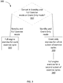
FIG. 3 is a flow chart for exercising a genset ofFIG. 1 . - Gensets are exercised on a regular basis to insure proper operation. In order to exercise a genset, the engine is either automatically or manually started and run for a period of time (for example, from 20 minutes to a few hours) at its nominal operating speed with or without a load. This exercise routine helps solve several problems related to a genset that sits unused for periods of time, such as clearing out stale fuel, lubricating engine parts, preventing carbon buildup at electrical contacts, cleaning rotor field slip rings and promoting good contact operation, etc. The exercise routine contributes to a more reliable genset and extends the life of the genset. However, it can be appreciated that the exercise of the genset produces unpleasant noise in the neighborhood. In addition, the exercise method draws in moisture to the engine which is not burned off, potentially leading to engine corrosion or engine lubrication oil degradation. As such, an exercise method with reduced noise that avoids drawing in damaging moisture to gensets is desired.
- Referring to the Figures generally, various embodiments disclosed herein relate to systems and methods of exercising a genset without providing fuel or enabling ignition to activate the genset during one or more exercise cycles. In particular, a "crank only exercise mode" is provided and, in some embodiments, may supplement an exercise routine in which the genset is provided with fuel and ignition function and operated during each exercise cycle. In the crank only exercise mode, fuel ignition does not happen (e.g., the fuel valve of the genset is shut off, and/or the ignition system of the genset is disabled, and/or the throttle is disabled, and/or the engine valve train is disabled, etc.) for at least some exercise cycles. The genset goes through a full crank cycle in, for example, 1 to 60 seconds (e.g., 5 seconds) but, because no fuel is provided and/or the ignition is disabled, ignition of the fuel will not happen. Diagnostics may be run on the battery, the alternator, the oil lube system, the temperature sensor, the speed sense circuitry, the excitation circuitry, the output voltage circuitry, etc. If any issues are detected, a user may be notified of the fault. Alternatively, a second or third crank only exercise may be run to see if the fault repeats (e.g., before notifying the user). If no issue is detected, the user may be notified of the successful exercise event. The crank only exercise can be set to be applied periodically, such as at every other scheduled exercise (e.g., weekly, biweekly, monthly, etc.). This crank only exercise provides many of the benefits of a normal genset exercise without consuming fuel and at a lower noise level. In addition, due to the brief running time and lack of thermal cycle, damaging moisture inherent from running many gaseous fuels will not be drawn to the engine, and greater engine reliability may be achieved, especially in gaseous genset applications.
- Referring to
FIG. 1 , a schematic diagram of agenset 100 with a crank only exercise mode is shown according to an exemplary embodiment. Thegenset 100 includes anengine 120, acommon shaft 128, analternator 130, acontroller 110, anoperator panel 140, astarter 150, amotive power shaft 152, and abattery 160. In various implementations, a genset may include fewer, greater, or different components than those shown inFIG. 1 . - The
engine 120 may drive the alternator 130 (also called a generator) through thecommon shaft 128. Theengine 120 may be a gas turbine engine, a gasoline engine, a diesel engine, or any other engine capable of supplying mechanical power to drive thegenerator 130. Theengine 120 includes, among others, afuel valve 122, anignition system 123, and acrankshaft 124. Other engine components (e.g., a combustor, an oil lube system, etc.) are omitted in the Figure for ease of explanation. Thefuel valve 122 may include a solenoid valve that can be turned on or off by thecontroller 110. When thefuel valve 122 is activated, fuel can be supplied to the combustor (not illustrated in the present Figure) of theengine 120. The fuel is then compressed and ignited by theignition system 123 within the cylinder(s) so as to generate reciprocating motion of pistons of theengine 120. The reciprocating motion of the pistons is converted to rotary motion by thecrankshaft 124 which, in turn, drives thealternator 130 through thecommon shaft 128. When thefuel valve 122 is turned off in the crank only exercise mode, no fuel is supplied. Additionally or alternatively, theignition system 123 is disabled in the crank only exercise mode, and/or the throttle (not illustrated in the present figures) is closed, and/or the engine valve train (not illustrated in the present figures) is deactivated, so that no ignition can happen. Thecrankshaft 124 is driven by thestarter 150 through themotive power shaft 152, which will be discussed in detail below with the description of thestarter 150. Thecrankshaft 124 may include aspeed sensor 126 structured to monitor the speed of thecrankshaft 124 and generate signals indicative of the speed for the use of the controller 110 (e.g., to maintain the speed above a speed where the starter is de-energized). - During a starting sequence before fuel is supplied and ignited (i.e., engine "cranking"), the
engine 120 receives motive power supplied by thestarter 150 through themotive power shaft 152 and/or starter gearing. Thestarter 150 may include a dedicated starter motor or any other machine capable of generating motive power, such as a starter-generator. Thecontroller 110 may generate start signals to actuate thestarter 150, which causes theengine 120 to accelerate (i.e., "crank") through a set of gears. - As shown in
FIG. 1 , thestarter 150 receives electrical power from thebattery 160. In other embodiments, thestarter 150 may receive power from other direct current (DC) or alternating current (AC) power sources. In some embodiments, thebattery 160 includes a rechargeable battery that supplied a voltage at 12 VDC. - The
alternator 130 may produce electrical power from the mechanical input supplied by theengine 120. Thealternator 130 includes, among others, theexciter 132 and thebattery charger 134. Other generator components (e.g., a rotor, a stator, etc.) are omitted in the Figure. Thealternator 130 may include a rotor that generates a moving magnetic field around a stator, which induces a voltage difference between windings of the stator. This produces an AC output of thegenset 100. The moving magnetic field may be produced by permanent magnets or by field coils. In the case of a genset with field coils, a current needs to flow in the field coils to generate the magnetic field. In other words, for a genset using field coils, a field current needs to be supplied during operations of the genset. The level of the field current determines the strength of the magnetic field. Theexciter 132 is the power source that supplies the field current. Theexciter 132 may receive field flash voltage from thebattery 160 in the starting sequence and voltage from a circuit drawing voltage from thegenerator 130 in a running state. Theexciter 132 may be a static-type exciter, a brush-type exciter, a brushless-type exciter, or any suitable type of exciter. Thebattery charger 134 is coupled to thebattery 160 in order to charge thebattery 160 by drawing power from thegenerator 130 in the running state. - The
operator panel 140 may serve as a user interface of thegenset 100. Theoperator panel 140 may be structured to convey information to a user on a display (not illustrated in the present Figures) and to receive a user input via, for example, a keypad, switches, and/or buttons. Theoperator panel 140 is communicably coupled with thecontroller 110 that is responsive to command signals generated through theoperator panel 140. - Referring to
FIG. 2 , a schematic diagram of a portion of theoperator panel 200 is shown according to an exemplary embodiment. Theoperator panel 200 may be used on, for example, thegenset 100 shown inFIG. 1 . Theoperator panel 200 includes, among others, a three-position rocker switch 201 to operate thegenset 100. In some implementations, therocker switch 201 can be used to select one of three operating modes, namely, "Start," "Off," and "Standby." When the "Standby" mode is enable, one of the two buttons, "Full Exercise"button 205 and "Crank Only"button 206, can be pressed. Therocker switch 201 may also include a lamp indicating whether thegenset 100 is running and/or providing genset fault codes. The Start mode may be selected by moving therocker switch 201 to atop position 202. In the Enabled mode, theengine 120 is activated. The Off mode may be selected by moving therocker switch 201 to amiddle position 203. In the Off mode, theengine 120 is turned off. The Standby mode may be selected by moving therocker switch 201 to abottom position 204. Only in the Standby mode can the exercise function be enabled. The "Full Exercise" mode may be selected by pressing the "Full Exercise"button 205. In the Full Exercise mode, theengine 120 may go through a full exercise during every exercise cycle. In the full exercise, thefuel valve 122 and theignition system 123 may be activated and fuel may be supplied to theengine 120 and ignited. Theengine 120 is then started and run for a period of time (for example, from 20 minutes to a few hours) at its nominal operating speed with or without a load. The Crank Only mode may be selected by pressing the "Crank Only"button 206. In the Crank Only mode, theengine 120 may go through the crank only exercise during at least some of the exercise cycles. In the crank only exercise, fuel ignition does not happen (e.g., thefuel valve 122 of thegenset 100 is turned off, and/or theignition system 123 is disabled, and/or the throttle is closed, and/or the engine valve train is deactivated). The genset may go through a full crank cycle, but since fuel is not provided and/or fuel is not ignited, fuel ignition will not occur. In some implementations, the engine cranking may have a duration of between 1 to 60 seconds (e.g., 5 seconds). In some embodiments, in the Crank Only mode, theengine 120 may go through the full exercise during some other exercise cycles. It shall be appreciated that the configuration of theoperator panel 200 shown inFIG. 2 is provided for purposes of illustration only. Other embodiments may include fewer, more, or different components than those illustrated inFIG. 2 . For example, theoperator panel 200 may display genset fault messages, time, battery state of charge, warning, mode, and other information to a user. - The
controller 110 may perform functions to start, stop, and crank thegenset 100 by controlling various components of thegenset 100. Thecontroller 110 is communicably coupled with theoperator panel 140 and responsive to command signals (i.e., Start, Off, Standby, Full Exercise, and Crank Only) generated through theoperator panel 140, and causes theoperator panel 140 to display information such as fault messages and battery information. Thecontroller 110 is communicably coupled to thestarter 150. In the full exercise, thecontroller 110 actuates thestarter 150 to accelerate theengine 120 during a start sequence and disable thestarter 150 when theengine 120 reaches a nominal speed (e.g., 3600 revolutions per minute (RPM) for a 60 Hz AC genset) based on speed data acquired from thespeed sensor 126. In some implementations, in the full exercise mode, theengine 120 may be gradually/slowly ramped up from a starting condition to a full power and/or full exercise speed. In the crank only exercise, thecontroller 110 actuates thestarter 150 to accelerate theengine 120 to a speed lower than the nominal speed (e.g., 400 to 1000 RPM). Thestarter 150 is disengaged after a full crank cycle is completed (e.g., in 1 to 60 seconds). Thecontroller 110 is communicably coupled with theengine 120 and selectively activates or deactivates thefuel valve 122 and/or theignition system 123. In the full engine exercise, thecontroller 110 turns on thefuel valve 122 and enables theignition system 123. As thestarter 122 accelerates theengine 120, fuel is supplied to theengine 120 through thefuel valve 122 and ignited by theignition system 123. Upon successful ignition of theengine 120 and once theengine 120 has reached a self-sustaining speed thestarter 150 is disengaged. In the crank only exercise, thecontroller 110 deactivates thefuel valve 122 and/or theignition system 123 and/or closes the throttle, and/or deactivates the engine valve train, so that ignition does not happen. Thecontroller 110 is communicably coupled to thegenerator 130 and controls the field current supplied by theexciter 132 through avoltage regulator 116, which will be discussed in detail below with the description of thevoltage regulator 116. Thecontroller 110 is communicably coupled to thebattery 160 and may acquire battery information such as state of charge. - The
controller 110 includes aprocessor 112, amemory 114, and avoltage regulator 116. Thevoltage regulator 116 may regulate output voltage of thegenset 100 by regulating the field current provided to theexciter 132 of thegenerator 130. As discussed above, the level of the field current determines the strength of the magnetic field, thereby determining the output voltage. In the full engine exercise, when the engine is started, theexciter 132 receives the field current from thebattery 160 to create an initial voltage, which in turn increases the field current, until thegenerator 130 builds up to full voltage. After the start sequence, the output of thegenerator 130 is fed up to thevoltage regulator 116 and serves as a source of the field current. In the crank only exercise, theexciter 132 receives the field current from thebattery 160 for the full crank cycle. In some embodiments, thevoltage regulator 116 may include a "feed-forward" design. In other embodiments, thevoltage regulator 116 may include negative feedback control loops, or any suitable design. Thevoltage regulator 116 may use electromechanical mechanism, electronic components, or any suitable components. Thevoltage regulator 116 is integrated into thecontroller 110 as shown inFIG. 1 . In other embodiments, thevoltage regulator 116 may be a separate component. - The
processor 112 may be implemented as a general-purpose processor, an application specific integrated circuit (ASIC), one or more field programmable gate arrays (FPGAs), a digital signal processor (DSP), a group of processing components, or other suitable electronic processing components. - The
memory 114 may be one or more memory devices (e.g., RAM, ROM, flash memory, hard disk storage, etc.) that stores data and/or computer code for facilitating the various processes described herein. Thus, thememory 114 may be communicably connected to theprocessor 112 and provide computer code or instructions to theprocessor 112 for executing the processes described in regard to thecontroller 110 herein. Moreover, thememory 114 may be or include tangible, non-transient volatile memory or non-volatile memory. Accordingly, thememory 114 may include database components, object code components, script components, or any other type of information structure for supporting the various activities and information structures described herein. - Although the
controller 110 is implemented as theprocessor 112 andmemory 114 in the embodiment shown inFIG. 1 , in other embodiments, thecontroller 110 may be implemented as dedicated hardware such as circuitry. - Communication between the
controller 110 and various components of thegenset 100 may be via any number of wired or wireless connections. For example, a wired connection may include a serial cable, a fiber optic cable, a CAT5 cable, or any other form of wired connection. In comparison, a wireless connection may include the Internet, Wi-Fi, cellular, radio, etc. In one embodiment, a controller area network (CAN) bus provides the exchange of signals, information, and/or data. The CAN bus may include any number of wired and wireless connections. - It shall also be appreciated that the configuration of the
generator 130 shown inFIG. 1 is provided for purposes of illustration only. Other embodiments may include fewer, more, or different components than those illustrated inFIG. 1 . - Referring to
FIG. 3 , aflow chart 300 for exercising a genset is shown according to an exemplary embodiment. The flow chart may be implemented on thegenset 100 and components shown inFIGS. 1 and2 . - At an operation 310, the
controller 110 detects whether thegenset 100 is in Standby mode, and, if so, whether thegenset 100 is in the Full Exercise mode or the Crank Only mode. As discussed above, the Full Exercise mode and the Crank Only mode may be disabled if thegenset 100 is not in the Standby mode. In some implementations, each of the Full Exercise mode and the Crank Only mode can be selected manually, such as by a user moving therocker switch 201 on thecontrol panel 200 to atop position 202 or abottom position 204. - At an
operation 320, in response to detecting thegenset 100 is in the Standby mode and the Full Exercise mode, thecontroller 110 implements a full exercise on theengine 120 at every exercise cycle, i.e., ignites fuel to activate thegenset 100. In some embodiments, activating the plurality of exercise cycles includes detecting whether a day and/or time maintained by the genset 100 (e.g., the controller 110) meets a predetermined day and/or time for any of the plurality of exercise cycles, and activating a particular exercise cycle in response to detecting that the day and/or time maintained by the genset meets the predetermined day and/or time for the particular exercise cycle. The day and/or time may be set by a user, such that the user determines the schedule at which exercise functions are set to occur. - In response to detecting the
genset 100 is in the Standby mode and the Crank Only mode, thecontroller 110 implements a crank only exercise on theengine 120 during at least a first subset of exercise cycles, at an operation 330. In some implementations, for a crank only exercise, thecontroller 110 prevents fuel ignition from happening, but actuates thestarter 150 to accelerate theengine 120 to a speed (e.g., 500 RPM) lower than the nominal speed (e.g., 3600 RPM). Thestarter 150 is disengaged after a full crank cycle is completed (e.g., in 1 - 60 seconds). Optionally, in response to detecting thegenset 100 is in the Crank Only mode, thecontroller 110 implements a full exercise on theengine 120 during a second subset of exercise cycles, at anoperation 340. In some implementations, for the Crank Only mode, the full engine exercise and the crank only exercise may be scheduled on a regular basis such as weekly, biweekly, monthly, etc. In some embodiments, thegenset 100 is arranged to alternate between the full exercise and the crank only exercise periodically, such as at every other scheduled exercise event, every third event, etc. - Automated testing and/or examination may be done on various components of the
genset 100 manually or automatically if any faults occur during the crank only exercise. Thecontroller 110 can diagnose and alert the user to also check whether thestarter 150 motor works properly and whether thestarter 150 circuit connections are loose or corroded. The user may remove thestarter 150 and check for broken teeth on the flywheel or broken starting motor springs. Thecontroller 110 can diagnose and alert the user to also check whether thespeed sensor 126 works properly. The user can further check whether thebattery 160 charge is low. If there is no AC output voltage from thegenerator 130 or the voltage is lower than desired, thecontroller 110 can diagnose and alert the user to check whether theexciter 132 circuit works properly, whether thebattery 160 charge is low, and whether thevoltage regulator 116 circuit works properly. - In some embodiments, additional diagnostics may be run automatically on the
battery 110, thealternator 120, thespeed sensor 126, thestarter 150, theexciter 130, thevoltage regulator 116, an oil lube system and a temperature sensor (not illustrated in the present FIGS.). For example, the state of charge (SoC) and/or state of health (SoH) of thebattery 160 may be checked. If the SoC or SoH is abnormal (e.g., out of a predetermined range), a corresponding fault code/information preassigned to this type of fault may be displayed on theoperator panel 140, providing a notification of the fault detected. Theexciter 132 circuit and thevoltage regulator 116 circuit may be checked by monitoring the AC output voltage from thegenerator 130. If there is no AC output voltage or the voltage is lower than desired, a corresponding fault code/information may be displayed on theoperator panel 140. - As discussed above, the
controller 110 may notify the user of the detected fault by displaying the corresponding fault code(s) on theoperator panel 140. In some implementations, the fault information may be provided by other means, such as by turning on warning lamps associated with various types of faults on thegenset 100 or generating sounds associated with various types of faults or through a remote monitoring system. In some embodiments, a notification may only be triggered if the fault appears in multiple crank cycles. In other words, in response to detecting the fault, thecontroller 110 may implement the crank only exercise on theengine 120 again. Thecontroller 110 may reactivate the diagnostic processes and determine whether the fault is reoccurring. If the fault has reoccurred, thecontroller 110 may provide a notification of the fault. If the fault has not reoccurred, thecontroller 110 may notify the user a successful exercise event or "diagnostic test pass" via theoperator panel 140 or a remote monitoring system. - In some embodiments, spinning of the
genset 100 in the Crank Only mode may be assisted by a secondary or external power source. For example, an AC power source may be fed into the stator of thegenset 100 and used to boost spinning of thegenset 100 during the crank only cycle. In some implementations, the external or secondary power may be provided by a battery or other energy storage device coupled to thegenset 100, a utility source coupled to thegenset 100, or another type of power source. - It should be noted that the term "example" as used herein to describe various embodiments is intended to indicate that such embodiments are possible examples, representations, and/or illustrations of possible embodiments (and such term is not intended to connote that such embodiments are necessarily extraordinary or superlative examples).
- Similarly, while operations may be depicted in a particular order, this should not be understood as requiring that such operations be performed in the particular order shown or in sequential order, or that all operations be performed, to achieve desirable results. Moreover, the separation of various aspects of the implementation described above should not be understood that the described methods can generally be integrated in a single application or integrated across multiple applications.
- The terms "coupled," "connected," and the like as used herein mean the joining of two members directly or indirectly to one another. Such joining may be stationary (e.g., permanent) or moveable (e.g., removable or releasable). Such joining may be achieved with the two members or the two members and any additional intermediate members being integrally formed as a single unitary body with one another or with the two members or the two members and any additional intermediate members being attached to one another.
- References herein to the positions of elements (e.g., "top," "bottom," etc.) are merely used to describe the orientation of various elements in the FIGURES. It should be noted that the orientation of various elements may differ according to other exemplary embodiments, and that such variations are intended to be encompassed by the present disclosure.
- It is important to note that the construction and arrangement of the various exemplary embodiments are illustrative only. Although only a few embodiments have been described in detail in this disclosure, those skilled in the art who review this disclosure will readily appreciate that many modifications are possible (e.g., variations in sizes, dimensions, structures, shapes and proportions of the various elements, values of parameters, mounting arrangements, use of materials, colors, orientations, etc.) without departing from the scope of the claims.
Claims (15)
- A method for exercising a genset (100), comprising:detecting whether the genset is in a full exercise mode or a crank only mode; andactivating a plurality of exercise cycles of the genset, wherein activating the plurality of exercise cycles comprises:in response to detecting the genset is in the full exercise mode, igniting fuel to activate the genset during each of the plurality of exercise cycles of the genset; andin response to detecting the genset is in the crank only mode, cranking the genset without igniting fuel during at least a first subset of the plurality of exercise cycles.
- The method of claim 1, wherein each of the full exercise mode and the crank only mode is selected via an operator panel (140) of the genset (100).
- The method of claim 1 or 2, wherein activating the plurality of exercise cycles further comprises, in response to detecting the genset (100) is in the crank only mode, igniting fuel to activate the genset during a second subset of the plurality of exercise cycles.
- The method of claim 3, further comprising scheduling the first subset and the second subset of the plurality of exercise cycles to activate periodically in response to detecting the genset (100) is in the crank only mode.
- The method of claim 3, further comprising alternating between the first subset and the second subset of the plurality of exercise cycles during every other exercise cycle in response to detecting the genset (100) in the crank only mode.
- The method of any of the preceding claims, wherein activating the plurality of exercise cycles further comprises:detecting whether a time maintained by the genset (100) meets a predetermined time for any of the plurality of exercise cycles; andactivating a particular exercise cycle in response to detecting that the time maintained by the genset meets the predetermined time for the particular exercise cycle.
- The method of any of the preceding claims, wherein the cranking the genset (100) comprises:actuating a starter (150) of the genset to accelerate the engine (120) to a speed lower than a nominal speed of the genset; andactuating an exciter (132) of the genset to provide a field current to a generator (130) of the genset.
- The method of any of the preceding claims, wherein cranking the genset (100) without igniting fuel comprises cranking the genset for a duration of between 1 to 60 seconds.
- The method of any of the preceding claims, wherein cranking the genset without igniting fuel comprises at least one of deactivating a fuel valve (122), deactivating an ignition system (123), closing a throttle, or deactivating an engine valve train.
- The method of any of the preceding claims, further comprising:activating one or more diagnostic processes on at least one of a starter (150), a battery (160), an alternator (130), an oil lube system, a temperature sensor, a speed sensor (126), an exciter (132), or a voltage regulator (116) of the genset while cranking the genset without igniting fuel; andobtaining diagnostic data while the diagnostic processes are active.
- The method of claim 10, further comprising:detecting a fault in the diagnostic data; andproviding a notification of the fault.
- The method of claim 10, further comprising:detecting a fault in the diagnostic data;in response to detecting the fault, cranking the genset again, reactivating the diagnostic processes, and determining whether the fault is reoccurring; andin response to detecting reoccurrence of the fault, providing a notification of the fault.
- The method of claim 10, further comprising:
providing a notification of a successful exercise event in response to not detecting any fault in the diagnostic data. - A controller (110) for controlling a genset (100), the controller configured to:detect whether the genset (100) is in a full exercise mode or a crank only mode;in response to detecting the genset is in the full exercise mode, ignite fuel to activate the genset during each of a plurality of exercise cycles of the genset; andin response to detecting the genset is in the crank only mode, crank the genset without igniting fuel during at least a first subset of the plurality of exercise cycles.
- A genset (100) comprising:an engine (120) including a fuel valve (122) and an ignition system (123);a starter (150) connected to the engine (120);an alternator (130) connected to the engine (120);an exciter (132) electrically connected to the alternator (130); anda controller according to claim 14 configured to:in response to detecting the genset is in the crank only mode:ignite fuel to activate the genset during a second subset of the plurality of exercise cycles; andcrank the genset without igniting fuel during the first subset of the plurality of exercise cycles, wherein cranking the engine (120) comprises:actuating the starter (150) to accelerate the engine (120) to a predetermined speed lower than a nominal speed of the genset; andactuating the exciter (132) to provide a field current to thegenerator (130); andactivate one or more diagnostic processes on at least one of the starter (150), a battery (160), the alternator (130), an oil lube system, a temperature sensor, a speed sensor (126), the exciter (132), or a voltage regulator (116) of the genset while cranking the genset without igniting fuel in the crank only mode;obtain diagnostic data while the diagnostic processes are active;detect a fault in the diagnostic data; andprovide a notification of the fault.
Applications Claiming Priority (2)
| Application Number | Priority Date | Filing Date | Title |
|---|---|---|---|
| US15/006,846 US9874190B2 (en) | 2016-01-26 | 2016-01-26 | Crank only exercise mode |
| PCT/US2017/014765 WO2017132160A1 (en) | 2016-01-26 | 2017-01-24 | Crank only exercise mode |
Publications (3)
| Publication Number | Publication Date |
|---|---|
| EP3408933A1 EP3408933A1 (en) | 2018-12-05 |
| EP3408933A4 EP3408933A4 (en) | 2019-10-02 |
| EP3408933B1 true EP3408933B1 (en) | 2021-10-20 |
Family
ID=59358940
Family Applications (1)
| Application Number | Title | Priority Date | Filing Date |
|---|---|---|---|
| EP17744772.9A Active EP3408933B1 (en) | 2016-01-26 | 2017-01-24 | Crank only exercise mode |
Country Status (4)
| Country | Link |
|---|---|
| US (1) | US9874190B2 (en) |
| EP (1) | EP3408933B1 (en) |
| CN (1) | CN108604874B (en) |
| WO (1) | WO2017132160A1 (en) |
Families Citing this family (7)
| Publication number | Priority date | Publication date | Assignee | Title |
|---|---|---|---|---|
| US10008965B2 (en) | 2016-01-26 | 2018-06-26 | Cummins Power Generation Ip, Inc. | Genset remote start control |
| US10102690B2 (en) * | 2016-03-04 | 2018-10-16 | Deere & Company | Non-starting engine remote diagnostic |
| US10584656B2 (en) | 2016-10-03 | 2020-03-10 | Briggs & Stratton Corporation | Standby generator and controls for generator exercise cycle |
| US11466638B2 (en) | 2017-10-24 | 2022-10-11 | Deere & Company | Sensor diagnostic procedure |
| US10920665B2 (en) | 2018-07-25 | 2021-02-16 | Briggs & Stratton, Llc | Standby generator including multiple exercise cycles with ambient temperature control |
| US10924043B2 (en) * | 2018-11-26 | 2021-02-16 | Cummins Power Generation Limited | Generator set exercising system |
| CN112152391B (en) * | 2020-08-25 | 2022-08-12 | 江苏理文造纸有限公司 | Heat regenerative system of cogeneration unit |
Citations (1)
| Publication number | Priority date | Publication date | Assignee | Title |
|---|---|---|---|---|
| US20060152198A1 (en) * | 2005-01-12 | 2006-07-13 | Winnie Peter D | Method for exercising a stand-by electrical generator |
Family Cites Families (23)
| Publication number | Priority date | Publication date | Assignee | Title |
|---|---|---|---|---|
| US743331A (en) | 1903-09-04 | 1903-11-03 | Elias E Ries | Means for removing sleet, &c., from electrical conductors. |
| GB1416741A (en) | 1972-03-30 | 1975-12-03 | Kidd Ltd Archie | Stand-by generators |
| DE4133059A1 (en) * | 1991-10-04 | 1993-04-08 | Mannesmann Ag | DRIVE ARRANGEMENT FOR A MOTOR VEHICLE |
| US6276472B1 (en) * | 1998-04-01 | 2001-08-21 | Denso Corporation | Control system for hybrid vehicle |
| US6074246A (en) | 1999-04-27 | 2000-06-13 | Electro Industries Inc | Meter extender mount for generator interface |
| US6420801B1 (en) | 2000-04-11 | 2002-07-16 | Electro Industries, Inc. | Alternative power supply connection |
| US6351692B1 (en) | 2000-10-24 | 2002-02-26 | Kohler Co. | Method and apparatus for configuring a genset controller for operation with particular gensets |
| US7332015B2 (en) | 2002-09-06 | 2008-02-19 | Waukesha Electric Systems, Inc | Automatic dehydrating breather apparatus and method |
| US7353084B2 (en) | 2003-02-27 | 2008-04-01 | Acutra, Inc. | Generator controller |
| JP2008029092A (en) | 2006-07-20 | 2008-02-07 | Mitsubishi Electric Corp | Gas dryer for internal cooling of electric machines |
| GB2450758A (en) | 2007-07-06 | 2009-01-07 | Cummins Generator Technologies | Device for reducing moisture in a rotating electrical machine |
| JP5035895B2 (en) * | 2007-09-27 | 2012-09-26 | 本田技研工業株式会社 | Power generation control device |
| US8291716B2 (en) | 2008-10-08 | 2012-10-23 | The Invention Science Fund I Llc | Hybrid propulsive engine including at least one independently rotatable turbine stator |
| US20100186373A1 (en) | 2008-12-09 | 2010-07-29 | Patrick Pierz | Exhaust Heating for Gensets |
| DE102009028374A1 (en) | 2009-08-10 | 2011-02-17 | Robert Bosch Gmbh | Method and device for adapting and / or diagnosing an internal combustion engine arranged in a hybrid vehicle |
| US8683980B2 (en) * | 2010-01-28 | 2014-04-01 | Cummins Power Generation, Inc. | Genset engine with an electronic fuel injection system integrating electrical sensing and crank position sensing |
| US8369068B2 (en) | 2010-05-21 | 2013-02-05 | Generac Power Systems, Inc. | Transfer switch enclosure |
| US8483982B2 (en) | 2010-11-02 | 2013-07-09 | Schneider Electric USA, Inc. | Automated emergency power supply test using variable load bank stages |
| GB201120114D0 (en) * | 2011-11-22 | 2012-01-04 | Land Rover Uk Ltd | Hybrid electric vehicle and method of control thereof |
| CN102570744A (en) | 2011-12-16 | 2012-07-11 | 无锡市南方防爆电机有限公司 | Explosion-proof motor shell dehumidification machining technology |
| CN202535220U (en) | 2012-04-10 | 2012-11-14 | 扬州市华胜机电制造有限公司 | Heatable moisture-removing motor |
| CN203386091U (en) | 2013-08-07 | 2014-01-08 | 宁波中策动力机电集团有限公司 | Generator set moisture-removing device based on automation technology |
| US10041421B2 (en) * | 2015-02-27 | 2018-08-07 | Kohler Co. | Safety system for engine shutdown, and engines and equipment incorporating the same |
-
2016
- 2016-01-26 US US15/006,846 patent/US9874190B2/en active Active
-
2017
- 2017-01-24 CN CN201780008529.XA patent/CN108604874B/en active Active
- 2017-01-24 WO PCT/US2017/014765 patent/WO2017132160A1/en not_active Ceased
- 2017-01-24 EP EP17744772.9A patent/EP3408933B1/en active Active
Patent Citations (1)
| Publication number | Priority date | Publication date | Assignee | Title |
|---|---|---|---|---|
| US20060152198A1 (en) * | 2005-01-12 | 2006-07-13 | Winnie Peter D | Method for exercising a stand-by electrical generator |
Also Published As
| Publication number | Publication date |
|---|---|
| WO2017132160A1 (en) | 2017-08-03 |
| CN108604874B (en) | 2021-10-26 |
| US20170211535A1 (en) | 2017-07-27 |
| EP3408933A4 (en) | 2019-10-02 |
| EP3408933A1 (en) | 2018-12-05 |
| US9874190B2 (en) | 2018-01-23 |
| CN108604874A (en) | 2018-09-28 |
Similar Documents
| Publication | Publication Date | Title |
|---|---|---|
| US9874190B2 (en) | Crank only exercise mode | |
| US11336214B2 (en) | Carbon monoxide shutoff system for electric generator | |
| JP5817136B2 (en) | Engine starter protection device | |
| US20030169018A1 (en) | Method and apparatus for monitoring the state of the battery of a hybrid electric vehicle | |
| US20110175357A1 (en) | Redundant combustion engine starting systems for emergency generators | |
| JP2011001956A (en) | Split-type auxiliary power combustion and starting system | |
| JP2009057833A (en) | Internal combustion engine control device | |
| JP4013714B2 (en) | Engine control device | |
| CN105275705A (en) | Method and apparatus to evaluate a starter for an internal combustion engine | |
| JP2011024354A (en) | Engine generator | |
| JP2009025032A (en) | Battery state detection device and method, and output control device and method | |
| WO2013123943A2 (en) | An emergency start power plant | |
| US20150107542A1 (en) | Engine | |
| JP5970771B2 (en) | Idle stop control device | |
| WO2021117737A1 (en) | Straddled vehicle | |
| RU2510796C1 (en) | Starter-generator system for combustion engine | |
| EP1985843B1 (en) | Capacitor-discharge ignition system for internal combustion engine | |
| TW201701569A (en) | Range extender and charging method, power generation equipment and power generation equipment control method thereof | |
| JP2013194637A (en) | Engine control unit | |
| JP2007224832A (en) | Diagnostic device for internal combustion engine | |
| JP6851743B2 (en) | Jumping start judgment device | |
| JP2010190123A (en) | Operation management apparatus | |
| US7328100B2 (en) | Coil failure detection system for general-purpose engine | |
| WO2008009045A1 (en) | Multi-purpose drive system for a combustion engine | |
| JP3136912U (en) | Operation control device for refrigerator installed in automobile |
Legal Events
| Date | Code | Title | Description |
|---|---|---|---|
| STAA | Information on the status of an ep patent application or granted ep patent |
Free format text: STATUS: THE INTERNATIONAL PUBLICATION HAS BEEN MADE |
|
| PUAI | Public reference made under article 153(3) epc to a published international application that has entered the european phase |
Free format text: ORIGINAL CODE: 0009012 |
|
| STAA | Information on the status of an ep patent application or granted ep patent |
Free format text: STATUS: REQUEST FOR EXAMINATION WAS MADE |
|
| 17P | Request for examination filed |
Effective date: 20180724 |
|
| AK | Designated contracting states |
Kind code of ref document: A1 Designated state(s): AL AT BE BG CH CY CZ DE DK EE ES FI FR GB GR HR HU IE IS IT LI LT LU LV MC MK MT NL NO PL PT RO RS SE SI SK SM TR |
|
| AX | Request for extension of the european patent |
Extension state: BA ME |
|
| DAV | Request for validation of the european patent (deleted) | ||
| DAX | Request for extension of the european patent (deleted) | ||
| A4 | Supplementary search report drawn up and despatched |
Effective date: 20190830 |
|
| RIC1 | Information provided on ipc code assigned before grant |
Ipc: H02P 9/00 20060101AFI20190826BHEP Ipc: F02D 37/02 20060101ALI20190826BHEP Ipc: F02D 41/04 20060101ALI20190826BHEP Ipc: F02P 9/00 20060101ALN20190826BHEP |
|
| RIC1 | Information provided on ipc code assigned before grant |
Ipc: F02P 9/00 20060101ALN20200914BHEP Ipc: H02P 9/00 20060101AFI20200914BHEP Ipc: F02D 41/04 20060101ALI20200914BHEP Ipc: F02D 37/02 20060101ALI20200914BHEP |
|
| GRAP | Despatch of communication of intention to grant a patent |
Free format text: ORIGINAL CODE: EPIDOSNIGR1 |
|
| STAA | Information on the status of an ep patent application or granted ep patent |
Free format text: STATUS: GRANT OF PATENT IS INTENDED |
|
| RIC1 | Information provided on ipc code assigned before grant |
Ipc: F02D 37/02 20060101ALI20200921BHEP Ipc: F02D 41/04 20060101ALI20200921BHEP Ipc: F02P 9/00 20060101ALN20200921BHEP Ipc: H02P 9/00 20060101AFI20200921BHEP |
|
| INTG | Intention to grant announced |
Effective date: 20201026 |
|
| GRAJ | Information related to disapproval of communication of intention to grant by the applicant or resumption of examination proceedings by the epo deleted |
Free format text: ORIGINAL CODE: EPIDOSDIGR1 |
|
| STAA | Information on the status of an ep patent application or granted ep patent |
Free format text: STATUS: REQUEST FOR EXAMINATION WAS MADE |
|
| INTC | Intention to grant announced (deleted) | ||
| RIC1 | Information provided on ipc code assigned before grant |
Ipc: F02P 9/00 20060101ALN20210331BHEP Ipc: F02D 37/02 20060101ALI20210331BHEP Ipc: F02D 41/04 20060101ALI20210331BHEP Ipc: H02P 9/00 20060101AFI20210331BHEP |
|
| GRAP | Despatch of communication of intention to grant a patent |
Free format text: ORIGINAL CODE: EPIDOSNIGR1 |
|
| STAA | Information on the status of an ep patent application or granted ep patent |
Free format text: STATUS: GRANT OF PATENT IS INTENDED |
|
| INTG | Intention to grant announced |
Effective date: 20210507 |
|
| GRAS | Grant fee paid |
Free format text: ORIGINAL CODE: EPIDOSNIGR3 |
|
| GRAA | (expected) grant |
Free format text: ORIGINAL CODE: 0009210 |
|
| STAA | Information on the status of an ep patent application or granted ep patent |
Free format text: STATUS: THE PATENT HAS BEEN GRANTED |
|
| AK | Designated contracting states |
Kind code of ref document: B1 Designated state(s): AL AT BE BG CH CY CZ DE DK EE ES FI FR GB GR HR HU IE IS IT LI LT LU LV MC MK MT NL NO PL PT RO RS SE SI SK SM TR |
|
| REG | Reference to a national code |
Ref country code: GB Ref legal event code: FG4D |
|
| REG | Reference to a national code |
Ref country code: CH Ref legal event code: EP |
|
| REG | Reference to a national code |
Ref country code: IE Ref legal event code: FG4D |
|
| REG | Reference to a national code |
Ref country code: DE Ref legal event code: R096 Ref document number: 602017047907 Country of ref document: DE |
|
| REG | Reference to a national code |
Ref country code: AT Ref legal event code: REF Ref document number: 1440755 Country of ref document: AT Kind code of ref document: T Effective date: 20211115 |
|
| REG | Reference to a national code |
Ref country code: LT Ref legal event code: MG9D |
|
| REG | Reference to a national code |
Ref country code: NL Ref legal event code: MP Effective date: 20211020 |
|
| REG | Reference to a national code |
Ref country code: AT Ref legal event code: MK05 Ref document number: 1440755 Country of ref document: AT Kind code of ref document: T Effective date: 20211020 |
|
| PG25 | Lapsed in a contracting state [announced via postgrant information from national office to epo] |
Ref country code: RS Free format text: LAPSE BECAUSE OF FAILURE TO SUBMIT A TRANSLATION OF THE DESCRIPTION OR TO PAY THE FEE WITHIN THE PRESCRIBED TIME-LIMIT Effective date: 20211020 Ref country code: LT Free format text: LAPSE BECAUSE OF FAILURE TO SUBMIT A TRANSLATION OF THE DESCRIPTION OR TO PAY THE FEE WITHIN THE PRESCRIBED TIME-LIMIT Effective date: 20211020 Ref country code: FI Free format text: LAPSE BECAUSE OF FAILURE TO SUBMIT A TRANSLATION OF THE DESCRIPTION OR TO PAY THE FEE WITHIN THE PRESCRIBED TIME-LIMIT Effective date: 20211020 Ref country code: BG Free format text: LAPSE BECAUSE OF FAILURE TO SUBMIT A TRANSLATION OF THE DESCRIPTION OR TO PAY THE FEE WITHIN THE PRESCRIBED TIME-LIMIT Effective date: 20220120 Ref country code: AT Free format text: LAPSE BECAUSE OF FAILURE TO SUBMIT A TRANSLATION OF THE DESCRIPTION OR TO PAY THE FEE WITHIN THE PRESCRIBED TIME-LIMIT Effective date: 20211020 |
|
| PG25 | Lapsed in a contracting state [announced via postgrant information from national office to epo] |
Ref country code: IS Free format text: LAPSE BECAUSE OF FAILURE TO SUBMIT A TRANSLATION OF THE DESCRIPTION OR TO PAY THE FEE WITHIN THE PRESCRIBED TIME-LIMIT Effective date: 20220220 Ref country code: SE Free format text: LAPSE BECAUSE OF FAILURE TO SUBMIT A TRANSLATION OF THE DESCRIPTION OR TO PAY THE FEE WITHIN THE PRESCRIBED TIME-LIMIT Effective date: 20211020 Ref country code: PT Free format text: LAPSE BECAUSE OF FAILURE TO SUBMIT A TRANSLATION OF THE DESCRIPTION OR TO PAY THE FEE WITHIN THE PRESCRIBED TIME-LIMIT Effective date: 20220221 Ref country code: PL Free format text: LAPSE BECAUSE OF FAILURE TO SUBMIT A TRANSLATION OF THE DESCRIPTION OR TO PAY THE FEE WITHIN THE PRESCRIBED TIME-LIMIT Effective date: 20211020 Ref country code: NO Free format text: LAPSE BECAUSE OF FAILURE TO SUBMIT A TRANSLATION OF THE DESCRIPTION OR TO PAY THE FEE WITHIN THE PRESCRIBED TIME-LIMIT Effective date: 20220120 Ref country code: NL Free format text: LAPSE BECAUSE OF FAILURE TO SUBMIT A TRANSLATION OF THE DESCRIPTION OR TO PAY THE FEE WITHIN THE PRESCRIBED TIME-LIMIT Effective date: 20211020 Ref country code: LV Free format text: LAPSE BECAUSE OF FAILURE TO SUBMIT A TRANSLATION OF THE DESCRIPTION OR TO PAY THE FEE WITHIN THE PRESCRIBED TIME-LIMIT Effective date: 20211020 Ref country code: HR Free format text: LAPSE BECAUSE OF FAILURE TO SUBMIT A TRANSLATION OF THE DESCRIPTION OR TO PAY THE FEE WITHIN THE PRESCRIBED TIME-LIMIT Effective date: 20211020 Ref country code: GR Free format text: LAPSE BECAUSE OF FAILURE TO SUBMIT A TRANSLATION OF THE DESCRIPTION OR TO PAY THE FEE WITHIN THE PRESCRIBED TIME-LIMIT Effective date: 20220121 Ref country code: ES Free format text: LAPSE BECAUSE OF FAILURE TO SUBMIT A TRANSLATION OF THE DESCRIPTION OR TO PAY THE FEE WITHIN THE PRESCRIBED TIME-LIMIT Effective date: 20211020 |
|
| REG | Reference to a national code |
Ref country code: DE Ref legal event code: R097 Ref document number: 602017047907 Country of ref document: DE |
|
| PG25 | Lapsed in a contracting state [announced via postgrant information from national office to epo] |
Ref country code: SM Free format text: LAPSE BECAUSE OF FAILURE TO SUBMIT A TRANSLATION OF THE DESCRIPTION OR TO PAY THE FEE WITHIN THE PRESCRIBED TIME-LIMIT Effective date: 20211020 Ref country code: SK Free format text: LAPSE BECAUSE OF FAILURE TO SUBMIT A TRANSLATION OF THE DESCRIPTION OR TO PAY THE FEE WITHIN THE PRESCRIBED TIME-LIMIT Effective date: 20211020 Ref country code: RO Free format text: LAPSE BECAUSE OF FAILURE TO SUBMIT A TRANSLATION OF THE DESCRIPTION OR TO PAY THE FEE WITHIN THE PRESCRIBED TIME-LIMIT Effective date: 20211020 Ref country code: EE Free format text: LAPSE BECAUSE OF FAILURE TO SUBMIT A TRANSLATION OF THE DESCRIPTION OR TO PAY THE FEE WITHIN THE PRESCRIBED TIME-LIMIT Effective date: 20211020 Ref country code: DK Free format text: LAPSE BECAUSE OF FAILURE TO SUBMIT A TRANSLATION OF THE DESCRIPTION OR TO PAY THE FEE WITHIN THE PRESCRIBED TIME-LIMIT Effective date: 20211020 Ref country code: CZ Free format text: LAPSE BECAUSE OF FAILURE TO SUBMIT A TRANSLATION OF THE DESCRIPTION OR TO PAY THE FEE WITHIN THE PRESCRIBED TIME-LIMIT Effective date: 20211020 |
|
| PLBE | No opposition filed within time limit |
Free format text: ORIGINAL CODE: 0009261 |
|
| STAA | Information on the status of an ep patent application or granted ep patent |
Free format text: STATUS: NO OPPOSITION FILED WITHIN TIME LIMIT |
|
| PG25 | Lapsed in a contracting state [announced via postgrant information from national office to epo] |
Ref country code: MC Free format text: LAPSE BECAUSE OF FAILURE TO SUBMIT A TRANSLATION OF THE DESCRIPTION OR TO PAY THE FEE WITHIN THE PRESCRIBED TIME-LIMIT Effective date: 20211020 |
|
| REG | Reference to a national code |
Ref country code: CH Ref legal event code: PL |
|
| 26N | No opposition filed |
Effective date: 20220721 |
|
| REG | Reference to a national code |
Ref country code: BE Ref legal event code: MM Effective date: 20220131 |
|
| PG25 | Lapsed in a contracting state [announced via postgrant information from national office to epo] |
Ref country code: LU Free format text: LAPSE BECAUSE OF NON-PAYMENT OF DUE FEES Effective date: 20220124 Ref country code: AL Free format text: LAPSE BECAUSE OF FAILURE TO SUBMIT A TRANSLATION OF THE DESCRIPTION OR TO PAY THE FEE WITHIN THE PRESCRIBED TIME-LIMIT Effective date: 20211020 |
|
| PG25 | Lapsed in a contracting state [announced via postgrant information from national office to epo] |
Ref country code: SI Free format text: LAPSE BECAUSE OF FAILURE TO SUBMIT A TRANSLATION OF THE DESCRIPTION OR TO PAY THE FEE WITHIN THE PRESCRIBED TIME-LIMIT Effective date: 20211020 Ref country code: FR Free format text: LAPSE BECAUSE OF NON-PAYMENT OF DUE FEES Effective date: 20220131 Ref country code: BE Free format text: LAPSE BECAUSE OF NON-PAYMENT OF DUE FEES Effective date: 20220131 |
|
| PG25 | Lapsed in a contracting state [announced via postgrant information from national office to epo] |
Ref country code: LI Free format text: LAPSE BECAUSE OF NON-PAYMENT OF DUE FEES Effective date: 20220131 Ref country code: CH Free format text: LAPSE BECAUSE OF NON-PAYMENT OF DUE FEES Effective date: 20220131 |
|
| PG25 | Lapsed in a contracting state [announced via postgrant information from national office to epo] |
Ref country code: IE Free format text: LAPSE BECAUSE OF NON-PAYMENT OF DUE FEES Effective date: 20220124 |
|
| PG25 | Lapsed in a contracting state [announced via postgrant information from national office to epo] |
Ref country code: IT Free format text: LAPSE BECAUSE OF FAILURE TO SUBMIT A TRANSLATION OF THE DESCRIPTION OR TO PAY THE FEE WITHIN THE PRESCRIBED TIME-LIMIT Effective date: 20211020 |
|
| P01 | Opt-out of the competence of the unified patent court (upc) registered |
Effective date: 20230510 |
|
| PG25 | Lapsed in a contracting state [announced via postgrant information from national office to epo] |
Ref country code: HU Free format text: LAPSE BECAUSE OF FAILURE TO SUBMIT A TRANSLATION OF THE DESCRIPTION OR TO PAY THE FEE WITHIN THE PRESCRIBED TIME-LIMIT; INVALID AB INITIO Effective date: 20170124 |
|
| PG25 | Lapsed in a contracting state [announced via postgrant information from national office to epo] |
Ref country code: MK Free format text: LAPSE BECAUSE OF FAILURE TO SUBMIT A TRANSLATION OF THE DESCRIPTION OR TO PAY THE FEE WITHIN THE PRESCRIBED TIME-LIMIT Effective date: 20211020 Ref country code: CY Free format text: LAPSE BECAUSE OF FAILURE TO SUBMIT A TRANSLATION OF THE DESCRIPTION OR TO PAY THE FEE WITHIN THE PRESCRIBED TIME-LIMIT Effective date: 20211020 |
|
| PG25 | Lapsed in a contracting state [announced via postgrant information from national office to epo] |
Ref country code: MT Free format text: LAPSE BECAUSE OF FAILURE TO SUBMIT A TRANSLATION OF THE DESCRIPTION OR TO PAY THE FEE WITHIN THE PRESCRIBED TIME-LIMIT Effective date: 20211020 |
|
| PG25 | Lapsed in a contracting state [announced via postgrant information from national office to epo] |
Ref country code: TR Free format text: LAPSE BECAUSE OF FAILURE TO SUBMIT A TRANSLATION OF THE DESCRIPTION OR TO PAY THE FEE WITHIN THE PRESCRIBED TIME-LIMIT Effective date: 20211020 |
|
| PGFP | Annual fee paid to national office [announced via postgrant information from national office to epo] |
Ref country code: GB Payment date: 20260127 Year of fee payment: 10 |
|
| PGFP | Annual fee paid to national office [announced via postgrant information from national office to epo] |
Ref country code: DE Payment date: 20260128 Year of fee payment: 10 |