EP3408622B1 - Dispositif de montage d'un transducteur à ultrasons et débitmètre équipé d'un tel dispositif - Google Patents
Dispositif de montage d'un transducteur à ultrasons et débitmètre équipé d'un tel dispositif Download PDFInfo
- Publication number
- EP3408622B1 EP3408622B1 EP17706284.1A EP17706284A EP3408622B1 EP 3408622 B1 EP3408622 B1 EP 3408622B1 EP 17706284 A EP17706284 A EP 17706284A EP 3408622 B1 EP3408622 B1 EP 3408622B1
- Authority
- EP
- European Patent Office
- Prior art keywords
- piping
- transducer
- active surface
- longitudinal axis
- fluid
- Prior art date
- Legal status (The legal status is an assumption and is not a legal conclusion. Google has not performed a legal analysis and makes no representation as to the accuracy of the status listed.)
- Active
Links
Images

Classifications
-
- G—PHYSICS
- G01—MEASURING; TESTING
- G01F—MEASURING VOLUME, VOLUME FLOW, MASS FLOW OR LIQUID LEVEL; METERING BY VOLUME
- G01F1/00—Measuring the volume flow or mass flow of fluid or fluent solid material wherein the fluid passes through a meter in a continuous flow
- G01F1/66—Measuring the volume flow or mass flow of fluid or fluent solid material wherein the fluid passes through a meter in a continuous flow by measuring frequency, phase shift or propagation time of electromagnetic or other waves, e.g. using ultrasonic flowmeters
- G01F1/662—Constructional details
-
- G—PHYSICS
- G01—MEASURING; TESTING
- G01F—MEASURING VOLUME, VOLUME FLOW, MASS FLOW OR LIQUID LEVEL; METERING BY VOLUME
- G01F15/00—Details of, or accessories for, apparatus of groups G01F1/00 - G01F13/00 insofar as such details or appliances are not adapted to particular types of such apparatus
- G01F15/18—Supports or connecting means for meters
- G01F15/185—Connecting means, e.g. bypass conduits
Definitions
- the invention relates to a device for mounting an ultrasonic transducer, and more particularly to such a device adapted to mount said transducer in a pipe of a flow meter.
- the invention also relates to flow meters equipped with such mounting devices.
- the present invention applies to flow meters in which the transducer or at least its mounting device passes through the wall of the pipe to come into contact with the fluid whose flow rate is to be measured, as opposed to the flow meters in which the transducers and / or their mounting device is installed outside the pipe and whose measurement is performed by transmitting waves through the walls thereof.
- US5,531,124 also proposes to fill this cavity by means of a resin plug having an ultrasonic permeability similar to that of the fluid to be measured.
- a resin plug having an ultrasonic permeability similar to that of the fluid to be measured.
- such a plug causes attenuation of the signal that it is necessary to compensate.
- the face in contact with the fluid is inclined with respect to the measurement axis, which may lead to other measurement errors, for example due to refraction phenomena.
- such a plug is difficult to produce so that it has no overshoot or no withdrawal in the fluid passage.
- the document EP 2 333 495 proposes an ultrasonic flowmeter in which the transducers are mounted in a "connection piece" fixed on the pipe of the flowmeter.
- This connecting piece solves some turbulence problems around the junction with the pipe by providing a surface having a geometry substantially identical to that of the inner surface of the pipe of the flow meter, with the exception of an opening leading to the transducer.
- the transducer is mounted in this opening from the inside of the connection piece, before fixing on the pipe.
- Such an assembly has, in addition to the problem already mentioned zones of turbulence and stagnation of the fluid in the vicinity of the transducer, the disadvantage of leaving the transducer in contact with the fluid flowing in the pipe and to be very difficult to maintain, particularly when the connection piece is welded to the pipe.
- the invention therefore aims to provide a device for mounting an ultrasonic transducer which allows easy mounting of the transducer while minimizing any disturbances of the fluid flow.
- the invention also relates to such a mounting device that allows to master the geometry of the environment of the transducer to manage the fluid flow conditions around it.
- the invention is also directed to such a mounting device that minimizes the angular adjustments necessary to ensure that the transducers are properly aligned.
- the invention further aims at such a mounting device to achieve internal shapes of the pipeline difficult to obtain otherwise.
- the invention also aims at such a mounting device that allows to withstand high pressures in the measurement fluid.
- the invention also relates to such a mounting device which allows easy machining mounting holes of the device on the wall of the pipe, despite the possible presence of obstacles such as connecting flanges of the pipe.
- the invention also aims at such a mounting device allowing substantial material savings and machining of the flowmeter.
- the terms “inside” or “outside” are used in relation to the pipe passing through the flow meter.
- the inner surface of the pipe is the surface in contact with the fluid that flows through it.
- a housing opening to the outside of the pipe is a housing whose opening is not in contact with the fluid flowing through the pipe.
- the invention relates to a device for mounting an ultrasonic transducer adapted for mounting said transducer through a wall of a flow meter having a pipe inside which circulates a fluid, said device comprising a body adapted to open on an inner surface of said pipe by an orifice along a contour line forming an interface between said inner surface of the pipe and a surface of the body in contact with the fluid flowing in the pipe, such that any straight line, orthogonal to the contour line and tangential to the inner surface of the pipe at a point of the contour line is also tangent to said surface of the device at this point, characterized in that the device has a surface, said active surface, in contact with the fluid circulating in the pipe and in that this active surface is formed by ladit the surface of the body in contact with the fluid flowing in the pipe.
- the entire surface of the mounting device in contact with the fluid flowing in the pipe is formed by the active surface of the body.
- this surface can be formed in one piece with the body of the device, for example by molding, the shape of this surface can be fully mastered.
- the active surface being continuous, there can be no sealing problem of the mounting device, with the exception of the interface between this device and the pipe. However, this interface itself is perfectly smooth and has no roughness and / or no setback that could cause turbulence.
- the active surface is free of hole (s) allowing the insertion of the transducer and causing sharp edges at the interface between the transducer and the active surface and sealing problems.
- the sealing of a flowmeter equipped with such mounting devices is thus improved.
- the size of the active surface of the mounting device may be relatively large which in fact minimizes the amount of material, usually brass or stainless steel used for the walls of the pipe.
- said active surface is at least partially formed by a wall of the body having, opposite the active surface, a bearing face carrying the transducer.
- the transducer is thus placed opposite the active surface, away from the fluid flowing in the pipe.
- the wall of the body interposed between the transducer and the fluid may advantageously, depending on the material used, be dimensioned in thickness so as to adapt the acoustic impedance between the transducer and the fluid. It can then be envisaged to directly use a bare piezoelectric wafer in place of a coated transducer and thus achieve with the body a more economical integrated transducer.
- said active surface is free of sharp edges.
- the transducer is mounted in the body so as to have a direction of transmission / reception of ultrasound passing through a plane face, called the active face, of the active surface.
- the active face is parallel to the support face.
- the transmission / reception direction of the transducer is normal to both the bearing face and the active face. Therefore, the direction of transmission / reception of the transducer can be fixed by construction through the orientation of the body wall.
- the mounting device is adapted to orient the direction of transmission / reception of the transducer in a direction, called measurement direction, adapted to extend in a longitudinal plane of symmetry of the pipe and form a predetermined angle with a longitudinal axis thereof.
- This embodiment is particularly suitable for producing flowmeters comprising two transducers facing each other along a diagonal of the pipe for a direct flow measurement. It can also be used for flow meters in which the measurement is carried out by reflection of the ultrasonic waves on an inner surface of the pipe, for example along a path V or W.
- said active surface comprises a hollow recess extending in a longitudinal direction adapted to be parallel to a longitudinal axis of the pipe when the mounting device is mounted thereon.
- One of the walls of the recess is the wall defined by the bearing face and the active face so as to define the predetermined orientation angle of the measuring direction.
- the profile of the niche is such that any plane orthogonal to this longitudinal direction intersects the active surface in a single line.
- a flow meter making use of such a transducer mounting device is healthier and does not deteriorate the qualities of the fluid that passes through it.
- the active surface comprises, in the vicinity of said active face, reliefs adapted to modify a flow of the fluid.
- the presence of longitudinal striations or fin shapes placed at the connection of the active face with the active surface upstream of the active face, in the fluid flow can help regulate this flow in particularly turbulent regimes.
- the body of the device comprises the right of the bearing face an open housing having a concavity oriented away from the longitudinal axis of the pipe. Thanks to this housing and the bearing surface it has, it is easy to place the ultrasonic transducer away from the fluid on the one hand and in an optimal position for the emission and / or reception of ultrasonic waves.
- the wall thickness between the bearing face and the active face can be optimized to match the wavelength of the ultrasound and to minimize possible attenuation of the waves.
- the mounting device further comprises a shutter, adapted to cooperate with said housing to press the ultrasonic transducer against the bearing face.
- This shutter may comprise a flat face, parallel to the bearing surface of the housing, adapted to exert pressure on the transducer when the shutter is fixed in the housing.
- the shutter may include one or more cells provided with conductive contacts adapted to be connected to the terminals of the transducer on the one hand and serve as connection pins to an external electronic device.
- the mounting device is adapted to be mounted in the pipe in a direction orthogonal to a longitudinal axis thereof. Since the orientation of the transducer can be fixed by the body of the mounting device, it is possible and advantageous to arrange the mounting device so that it can be introduced radially into the pipe and fixed thereto, without the need to perform an oblique drilling on the pipe. As a result, the machining constraints of the pipe are reduced and the cost is reduced. In addition, the accuracy of the position of the transducer is improved.
- the mounting device further comprises a flange adapted to fix the body on said pipe, said flange comprising facing the body a projection in the form of a stirrup adapted to cooperate with a conjugate form of the body to stiffen this last.
- the projection in the form of a stirrup of the flange is housed in a complementary shape formed in the body of the mounting device and makes it possible to strengthen the body in order to be able to accept fluids under high pressure without deformation.
- the invention also extends to an ultrasonic flowmeter, of the type comprising a pipe for measuring the flow of a fluid and at least two ultrasonic transducers mounted opposite one another through a wall of said pipe, in the same longitudinal plane of symmetry of the pipeline, said transducers being oriented in a measurement direction forming a non-zero angle and less than 90 ° with the longitudinal axis of the pipe, characterized in that each transducer is installed in a mounting device having any of the above features.
- the mounting device is adapted to be mounted on a flowmeter comprising a pipe having a plenum chamber at each end thereof, each chamber having an ultrasonic transducer mounted such that the transmitting / receiving direction of the transducer is coincident with the longitudinal axis of said pipe.
- the mounting device is arranged such that the transducer associated with each device is vis-à-vis the other transducer, in the axis of the fluid flow when the mounting device is installed in the flow meter.
- the active surface of the body of the device forms at least a part of the wall of the chamber of tranquilization.
- the body of the mounting device forms a plug closing an orifice of the chamber through which the transducer is introduced, this plug having a continuity of shape with the plenum, at least around the contour line of the interface between the cap and the chamber.
- the active surface of the body of the device forms a cap whose contour line is at least partially comprised in a plane of symmetry of the plenum passing through the axis of the pipe.
- the plenum chamber is spherical, barrel-shaped or in the form of two cones connected by their large base by a cylinder of revolution
- the hollow shape of the chamber can be made in two parts, of shape and size. substantially identical and complementary, which simplifies the machining and / or molding of such shapes, or even to make them possible.
- the active surface also forms a hollow shell at least substantially cylindrical, called plunger, extending radially projecting towards the longitudinal axis of the pipe and of a length adapted to cut this axis.
- the plunger thus makes it possible to install the ultrasonic transducer inside the casing, on the longitudinal axis of the duct, facing another transducer installed in a symmetrical mounting device in the opposite plenum.
- the plunger comprises, at least on an inner face of the hollow envelope, a flat orthogonal to the longitudinal axis of the pipe, adapted to form a bearing wall for the ultrasonic transducer.
- the transducer may be mounted within the plunger in a predetermined orientation and be connected by electrical connections to the outside of the plenum.
- the invention also extends to an ultrasonic flowmeter, of the type comprising a pipe for measuring the flow of a fluid, said pipe having a plenum chamber at each end, each chamber having an ultrasonic transducer mounted in a screw-in position. -vis transducer the other chamber along a longitudinal axis of said pipe characterized in that each transducer is installed in a mounting device according to any of the features of the second embodiment of the invention.
- the invention also relates to a device for mounting an ultrasound transducer and an ultrasonic flowmeter characterized in combination by all or some of the characteristics mentioned above or below.
- the figure 1 represents, in longitudinal section, a flow meter 1 comprising a tube 3 forming a pipe 2 in which circulates a fluid whose flow rate is to be measured.
- the pipe 2 is cylindrical of revolution and has a longitudinal axis 4.
- the pipe 3 comprises two plates 20 ( Figure 3 ) molded or machined on the tube, diametrically opposite with respect thereto and spaced apart from each other along the longitudinal axis of the pipe.
- Each plate 20 has an orifice opening into the pipe 2.
- a device 5 for mounting an ultrasonic transducer 9 is installed in the orifice of each plate 20 and fixed on the tube 3.
- the mounting device 5 shown in more detail in figures 2 and 3 , comprises a body 6 formed in one piece, preferably molded of synthetic material, for example polyetherimide (PEI) for its temperature stability, whose shape is at least partly conjugated to that of the orifice to be able to be fixed on it.
- PEI polyetherimide
- the body 6 Once installed in the orifice, the body 6 has a surface, said active surface 15, in contact with the fluid 19 flowing in the pipe.
- the delimitation between the inner surface 16 of the pipe and the active surface 15 of the body 6 takes place along a closed line, called the contour line 14.
- the active surface 15 is the only part of the mounting device 5 in contact with the fluid. It extends continuously, without opening, over the entire area delimited by the contour line 14.
- the active surface 15 is such that any tangent to the inner surface 16 of the pipe along the contour line 14 and orthogonal to it is also tangent to the active surface 15.
- the interface between the two surfaces is perfectly smooth and can not generate recesses of fluid threads, turbulence or areas of stagnation of the fluid.
- the active surface of the body of the mounting device 5 is also cylindrical and of the same radius, at least in the vicinity of the contour line as shown in FIG. figure 3 .
- a flow meter 1 as illustrated in figure 1 two ultrasonic transducers 9 are installed facing each other in the pipe 2 in a measuring direction 12 forming a predetermined non-zero angle and less than 90 ° with the longitudinal axis 4 in a longitudinal plane of symmetry of the pipe .
- the angle between the measuring direction 12 and the longitudinal axis 4 of the pipe is of the order of 30 ° but can be up to 50 ° or more depending on the flowmeter models.
- Each transducer 9 is formed of a plate of piezoelectric material comprising two electrodes and protected by an outer coating of synthetic material of parallelepipedal shape very flattened. The main faces of the transducer are orthogonal to the direction of transmission / reception of ultrasonic waves.
- Each transducer 9 is mounted in a mounting device 5, passing through the tube 3 and opening into the pipe 2. The mounting devices 5 are placed on either side of the tube 3, so that the transducers 9 are placed vis-à-vis and that their respective transmission / reception direction coincides with the measurement direction 12.
- the transducer 9 Due to the continuity of the active surface, the transducer 9 is isolated from the fluid flowing in the pipe. It is therefore possible to directly use a wafer of piezoelectric material, without external coating instead of the coated transducer 9. As will be described later, the piezoelectric wafer may be fixed in the body 6 by a layer of adhesive or resin allowing part of a sound impedance matching between the piezoelectric wafer and the fluid. Therefore, the body 6 and the wafer of the transducer together form at least a portion of an integrated transducer.
- the body 6 has on its active surface 15 a hollow recess 10 whose concavity is oriented towards the inside of the pipe 2, that is to say in the direction of the longitudinal axis 4.
- This niche 10 extends in a longitudinal direction parallel to the longitudinal axis 4 of the pipe and comprises at least one flat face, said active face 11, orthogonal to the measurement direction 12.
- the other walls of the niche 10 may have any shape as long as these walls do not interfere with the ultrasonic waves.
- the niche 10 includes, as illustrated in detail on the figure 2 , an upper face parallel to the measuring direction 12 and two lateral faces parallel to the longitudinal plane of symmetry of the pipe containing the measuring direction 12.
- any plane orthogonal to the longitudinal direction of the niche cuts the active surface 15 only in a single line, that is to say that the profile of the recess, in longitudinal section, has no creep or backward movement relative to the direction of circulation fluid.
- the profile of the recess does not include any acute angle that could constitute a zone of recess of the fluid streams or a dead zone in which the fluid would be likely to stagnate.
- the active surface 15 and all the faces of the niche 10 therein are connected to each other and to the contour line 14 by surfaces free from sharp edges.
- all the flat surfaces are connected together by fills of sufficient radius not to create turbulence in the fluid streams.
- the fillet radius is of the order of 0.5 to 1 mm.
- the fluid flow can vary very significantly, resulting in transitions between various regimes, for example from a laminar regime to a turbulent regime as a function of fluid flow. It is then useful to provide certain reliefs at predetermined locations of the active surface 15, for example in the vicinity of the active face 11, in order to manage the disturbances related to these changes in regime.
- striations parallel to the direction of the fluid flow may be formed at the junction between the active face 11 and the active surface 15 upstream of the active face relative to the fluid flow, in order to regularize the direction fluid streams.
- Other geometric shapes, for example fins may be employed at various locations on the active surface to correct anomalies in the fluid flow under certain regimes. These shapes can be advantageously formed during the molding of the body 6.
- the body 6 comprises a housing 23, open towards the outside, that is to say whose concavity is oriented away from the axis 4.
- This housing comprises a so-called flat face bearing surface 21 parallel to the active face 11 of the recess 10 and delimiting with it a partition 24 on which the transducer 9 is fixed.
- the housing 23 receives a shutter 8 of shape adapted to substantially fill the housing 23, the shutter 8 having a face the shutter 8 is fixed in the housing 23 of the body 6 by any suitable fastening means, for example by screwing, latching, welding, gluing or riveting.
- the shutter 8 is made of synthetic material, preferably identical or compatible with that of the body 6, and has one or more cells 22 adapted to receive electrical contact means with the transducer 9, such as connector pins 18 which pass through. the shutter and come into contact with the pins of the transducer 9.
- the transducer 9 is simply a bare piezoelectric wafer, this wafer is glued on the bearing face 21 by adhesive or a suitable resin (for the adaptation of sound impedance) and pressed against this bearing face by the shutter 8 which forms a connector. Therefore, the body 6, the piezoelectric plate and the shutter form a solid block considered as an integrated transducer.
- the body 6 further comprises a flange 25 adapted to bear on the plate 20 all around the orifice formed in this plate.
- the flange 25 comprises on its periphery a groove adapted to receive a seal 26 between the rim 25 and the plate 20.
- the orientation of the transducer 9 in the measurement direction 12 is ensured by the inclination of the partition 24 and the bearing faces 21 and active 11. Therefore, it is possible to choose to insert the mounting device 5 and therefore the body 6 in the tube 3 in any direction.
- the mounting device 5 is adapted to be mounted on the tube 3 in a direction radial relative thereto, that is to say orthogonally to the longitudinal axis 4. Therefore, the rim 25 and the tray 20 may be parallel and orthogonal to the mounting direction which simplifies the machining of the mounting hole in the tube 3 and the assembly operations.
- the mounting device 5 finally comprises a flange 7 for fixing the body 6 on the plate 20 by means of screws (not shown) passing through bores 13.
- the flange 7 has a central lumen allowing the passage of the upper part of the body 6 so that the shutter 8 and the connections 18 are accessible from the outside once the mounting device 5 in position on the tube 3.
- the figure 4 is a perspective bottom view of the flange 7 showing the presence of a stirrup 17 projecting on the underside of the flange 7 and adapted to cooperate with a conjugate profile formed in the body 6 to facilitate the orientation of the in the axis of the tube 3 and strengthen the rigidity of the body 6, particularly in the case where the fluid flowing in the pipe is under high pressure.
- the flange 7 can be made of synthetic material, optionally loaded with glass or carbon fibers to improve the rigidity or even metal, preferably stainless steel. Of course, the flange 7 may also be integral with the body 6, for example molded simultaneously in one piece.
- the flow meter 30 is in the general form of a tube 33 terminated at both ends by threaded connections 43. Between the connectors 43, the pipe 32 is traversed by a fluid 34 and comprises three tubular sections separated by two chambers 31 of tranquilization located on either side of the central tubular section. Two ultrasonic transducers 39 are placed facing each other, on either side of the central tubular section, on a longitudinal axis 44 of the pipe 32, inside the chambers 31.
- each chamber 31 has a profile in the form of two truncated cones separated by a cylinder section, these three parts being coaxial with each other and with the longitudinal axis 44 of the tubular sections.
- the small base of each truncated cone has a diameter equal to the diameter of the pipe and the large base of each truncated cone has a diameter equal to that of the cylinder section.
- Such a form of channeling would be very difficult, if not impossible to obtain without providing a removable part. It is the same for example for a spherical or quasi-spherical chamber.
- each chamber 31 is formed in two parts, a first part obtained from the tube 33 and a second part formed from the body 40 of a device 35 of the transducer 39.
- the two parts of the chamber 31 join together along a contour line 36.
- the inner surface of the portion of the chamber 31 coming from the tube 33 and the surface, said surface 38 of the part of the chamber from the mounting device 35, in contact with the fluid are such that along the contour line 36, a line tangent to one of the surfaces, orthogonal to the contour line is also tangent to the other surface.
- the active surface 38 of the mounting device 35 forms a surface continuity with the tube 33 to form the plenum.
- the active surface 38 forms a symmetrical cap of the inner surface of the tube 33 and the contour line 36 belongs at least in part to the plane of symmetry passing through the longitudinal axis 44 of the pipe 32.
- the plenum chamber 31 is thus formed of two half-shells of substantially identical size.
- the mounting device 35 also comprises in its active surface, a hollow envelope, called plunger 37, of generally cylindrical shape and of axis orthogonal to the longitudinal axis 44 of the pipe.
- This plunger 37 has an axial opening towards the outside of the pipe 32 adapted to allow the insertion and the fixing of a transducer 39 so that the direction of transmission / reception of this transducer coincides with the longitudinal axis of the pipeline.
- the plunger 37 comprises, at least on its inner surface, a flat 41 orthogonal to the longitudinal axis of the pipe.
- the flat 41 is formed on the inner and outer surfaces of the plunger.
- the transducer 39 can then be fixed, for example by gluing, on the inner face of the flat part 41, away from the fluid.
- the interior of the plunger can then be closed by pouring a resin.
- the transducer 39 can be fixed on a shutter (not shown) of shape conjugate to that of the inside of the plunger, this shutter then being inserted into the plunger 37.
- the body 40 of the mounting device 35 has a substantially cylindrical outer surface, of axis orthogonal to the longitudinal axis 44 of the pipe and of diameter adapted to cooperate with a mounting hole formed in the tube 33. It is thus possible to radially insert the mounting device 35 into the tube 32.
- the body 40 is further surmounted by a flange 42 adapted to fix the mounting device 35 on the tube 32.
- the flange 42 comprises, at the periphery of the body 40 a groove 45 adapted to receive a seal.
- the mounting device 35 is made in one piece by molding plastic, which allows a precise and particularly economical manufacturing.
- the flow meter 30 may thus consist of a tube 33 and two identical mounting devices 35, each equipped with a transducer 39 and mounted facing each other on either side of a central tubular section of the channeling, each mounting device 35 completing the tube 33 to form a plenum 31.
Landscapes
- Physics & Mathematics (AREA)
- Electromagnetism (AREA)
- Fluid Mechanics (AREA)
- General Physics & Mathematics (AREA)
- Measuring Volume Flow (AREA)
Description
- L'invention concerne un dispositif de montage d'un transducteur à ultrasons, et plus particulièrement un tel dispositif adapté pour monter ledit transducteur dans une canalisation d'un débitmètre. L'invention concerne également des débitmètres équipés de tels dispositifs de montage.
- Il existe de nombreuses catégories de débitmètres à ultrasons, dans lesquels le débit d'un fluide est mesuré par la vitesse de propagation d'ultrasons dans le milieu fluide circulant dans une canalisation.
- La présente invention s'applique aux débitmètres dans lesquels le transducteur ou au moins son dispositif de montage traverse la paroi de la canalisation pour rentrer en contact avec le fluide dont le débit est à mesurer, par opposition aux débitmètres dans lesquels les transducteurs et/ou leur dispositif de montage est installé à l'extérieur de la canalisation et dont la mesure est effectuée par transmission d'ondes au travers des parois de celle-ci.
- On connait, par exemple du document
US 5,531,124 , en particulier figures 9 et 10, un débitmètre à ultrasons dans lequel les transducteurs sont montés en regard l'un de l'autre dans des trous percés en diagonale dans la paroi de la canalisation. Cependant, outre le coût et la difficulté de réaliser un tel perçage en diagonale avec la précision requise, en particulier dans un matériau tel que l'acier inoxydable, le positionnement du transducteur, avec ou sans dispositif de montage, présente de nombreux inconvénients. En effet, si le transducteur est inséré dans le trou sans déborder à l'intérieur de la canalisation, il se forme du fait de l'inclinaison, une cavité devant le transducteur qui est le siège de turbulences et/ou de zones de stagnation du fluide qui perturbent la mesure et peuvent générer un encrassement devant les transducteurs.US 5,531,124 propose également de combler cette cavité au moyen d'un bouchon de résine présentant une perméabilité aux ultrasons analogue à celle du fluide à mesurer. Cependant, un tel bouchon cause une atténuation du signal qu'il est nécessaire de compenser. En outre, la face en contact avec le fluide est inclinée par rapport à l'axe de mesure, ce qui peut entrainer d'autres erreurs de mesure, par exemple dues à des phénomènes de réfraction. De plus, un tel bouchon est délicat à réaliser de manière à ce qu'il ne présente aucun dépassement ou aucun retrait dans le passage de fluide. - Le document
EP 2 333 495 propose un débitmètre à ultrasons dans lequel les transducteurs sont montés dans une "pièce de connexion" fixée sur la canalisation du débitmètre. Cette pièce de connexion résout certains problèmes de turbulence autour de la jonction avec la canalisation en proposant une surface présentant une géométrie substantiellement identique à celle de la surface intérieure de la canalisation du débitmètre, à l'exception d'une ouverture menant au transducteur. Le transducteur est monté dans cette ouverture par l'intérieur de la pièce de connexion, avant fixation sur la canalisation. Un tel montage présente, outre le problème déjà cité des zones de turbulence et de stagnation du fluide au voisinage du transducteur, l'inconvénient de laisser le transducteur au contact du fluide circulant dans la canalisation et d'être très difficile à maintenir, particulièrement lorsque la pièce de connexion est soudée à la canalisation. - On connait également du document
US 3,817,098 ou du documentUS 5,905,207 un débitmètre, plus particulièrement adapté à la mesure précise de faibles débits, qui présente deux transducteurs en vis-à-vis selon un axe longitudinal d'une canalisation, chaque transducteur étant placé dans une chambre de tranquillisation à chaque extrémité de la portion de canalisation dans laquelle s'effectue la mesure. Cependant, la réalisation de telles chambres de tranquillisation, ainsi que l'installation des transducteurs en vis-à-vis présente de nombreuses difficultés, par exemple liées à l'usinage des chambres. - L'invention vise donc à fournir un dispositif de montage d'un transducteur à ultrasons qui permet un montage aisé du transducteur tout en minimisant les éventuelles perturbations du flux de fluide.
- L'invention vise également un tel dispositif de montage qui permet de maitriser la géométrie de l'environnement du transducteur afin de gérer les régimes d'écoulement du fluide autour de celui-ci.
- L'invention vise encore un tel dispositif de montage qui minimise les ajustements angulaires nécessaires pour assurer que les transducteurs sont bien alignés.
- L'invention vise de plus un tel dispositif de montage permettant de réaliser des formes internes de la canalisation difficiles à obtenir autrement.
- L'invention vise en outre un tel dispositif de montage qui permette de supporter de fortes pressions dans le fluide de mesure.
- L'invention vise encore un tel dispositif de montage qui permet un usinage facilité des orifices de montage du dispositif sur la paroi de la canalisation, malgré la présence éventuelle d'obstacles tels que des brides de raccordement de la canalisation.
- L'invention vise également un tel dispositif de montage permettant de substantielles économies de matière et d'usinage du débitmètre.
- Dans le présent texte, on utilise les termes "intérieur" ou "extérieur" en relation avec la canalisation traversant le débitmètre. Ainsi, la surface intérieure de la canalisation est la surface en contact avec le fluide qui la parcourt. De même, un logement s'ouvrant vers l'extérieur de la canalisation est un logement dont l'ouverture n'est pas en contact avec le fluide qui parcourt la canalisation.
- Pour atteindre les buts de l'invention, l'invention concerne un dispositif de montage d'un transducteur à ultrasons adapté pour le montage dudit transducteur au travers d'une paroi d'un débitmètre comportant une canalisation à l'intérieur de laquelle circule un fluide, ledit dispositif comportant un corps adapté pour déboucher sur une surface intérieure de ladite canalisation par un orifice selon une ligne de contour formant une interface entre ladite surface intérieure de la canalisation et une surface du corps en contact avec le fluide circulant dans la canalisation, telle que toute droite, orthogonale à la ligne de contour et tangente à la surface intérieure de la canalisation en un point de la ligne de contour est également tangente à ladite surface du dispositif en ce point, caractérisé en ce que le dispositif présente une surface, dite surface active, en contact avec le fluide circulant dans la canalisation et en ce que cette surface active est formée par ladite surface du corps en contact avec le fluide circulant dans la canalisation.
- Grâce à cette disposition, toute la surface du dispositif de montage en contact avec le fluide circulant dans la canalisation est constituée par la surface active du corps. Il n'existe donc pas de trou, coupure ou discontinuité dans cette surface active, susceptible d'engendrer des turbulences dans le flux de fluide. En outre, cette surface pouvant être formée en une seule pièce avec le corps du dispositif, par exemple par moulage, la forme de cette surface peut être entièrement maitrisée. De plus, la surface active étant continue, il ne peut y avoir de problème d'étanchéité du dispositif de montage, à l'exception de l'interface entre ce dispositif et la canalisation. Cependant, cette interface elle-même est parfaitement lisse et ne présente aucune aspérité et/ou aucun décrochement qui pourrait être cause de turbulences. En outre, la surface active est exempte de trou(s) permettant l'insertion du transducteur et entrainant des arêtes vives à l'interface entre le transducteur et la surface active ainsi que des problèmes d'étanchéité.
- L'étanchéité d'un débitmètre équipé de tels dispositifs de montage est ainsi améliorée. En outre, la taille de la surface active du dispositif de montage peut être relativement importante ce qui minimise de fait la quantité de matière, en général du laiton ou de l'acier inoxydable utilisée pour les parois de la canalisation.
- Avantageusement et selon l'invention, ladite surface active est au moins partiellement formée par une paroi du corps présentant à l'opposé de la surface active une face d'appui portant le transducteur. Le transducteur est ainsi placé à l'opposé de la surface active, à l'abri du fluide circulant dans la canalisation. La paroi du corps intercalée entre le transducteur et le fluide peut avantageusement, en fonction du matériau employé, être dimensionnée en épaisseur de manière à adapter l'impédance acoustique entre le transducteur et le fluide. Il peut alors être envisagé d'utiliser directement une plaquette piézoélectrique nue en lieu et place d'un transducteur enrobé et ainsi réaliser avec le corps un transducteur intégré plus économique.
- Avantageusement et selon l'invention, ladite surface active est exempte d'arêtes vives. En formant la surface active avec des surfaces arrondies, des congés de raccordement au lieu d'angles vifs, etc. jusqu'à l'interface entre la surface active et la surface intérieure de la canalisation, le trajet des lignes de flux de fluide est maitrisé et permet un écoulement sans zones de stagnation du fluide.
- Avantageusement et selon l'invention, le transducteur est monté dans le corps de manière à présenter une direction d'émission / réception d'ultrasons traversant une face plane, dite face active, de la surface active. Préférentiellement, la face active est parallèle à la face d'appui. Ainsi, la direction d'émission / réception du transducteur est normale tant à la face d'appui qu'à la face active. Dès lors, la direction d'émission / réception du transducteur peut être fixée par construction grâce à l'orientation de la paroi du corps.
- Selon un premier mode de réalisation avantageux de l'invention, le dispositif de montage est adapté pour orienter la direction d'émission / réception du transducteur selon une direction, dite direction de mesure, adaptée pour s'étendre dans un plan de symétrie longitudinale de la canalisation et former un angle prédéterminé avec un axe longitudinal de celle-ci. Ce mode de réalisation est particulièrement adapté pour la réalisation de débitmètres comportant deux transducteurs en vis-à-vis selon une diagonale de la canalisation pour une mesure de débit directe. Il peut également être utilisé pour des débitmètres dans lesquels la mesure s'effectue par réflexion des ondes ultrasonores sur une surface intérieure de la canalisation, par exemple selon un trajet en V ou en W.
- Avantageusement et selon l'invention, ladite surface active comporte une niche en creux s'étendant selon une direction longitudinale adaptée pour être parallèle à un axe longitudinal de la canalisation lorsque le dispositif de montage est monté sur celle-ci. L'une des parois de la niche est la paroi définie par la face d'appui et la face active de manière à définir l'angle d'orientation prédéterminé de la direction de mesure. Ainsi, l'émission et/ou la réception des ondes ultrasonores est effectuée directement dans la direction de mesure, sans perturbations liées à d'éventuelles erreurs d'angle de perçage influant sur l'angle d'incidence des ondes. La forme et la profondeur de la niche sont adaptées pour ne pas entrainer de turbulences ou de stagnation des lignes de flux de fluide.
- En particulier et à cet effet, le profil de la niche est tel que tout plan orthogonal à cette direction longitudinale coupe la surface active en une seule ligne. Il ne peut donc pas y avoir de partie en retrait, c'est-à-dire formant un trajet de fluide présentant un retour en arrière ou un rebroussement du flux qui causerait une zone de stagnation susceptible de permettre des dépôts d'impuretés ou des proliférations bactériennes dans le cas d'un débitmètre pour la mesure d'un débit d'eau potable. Ainsi, un débitmètre faisant usage d'un tel dispositif de montage d'un transducteur est plus sain et ne détériore pas les qualités du fluide qui le traverse.
- Avantageusement et selon l'invention, la surface active comporte, au voisinage de ladite face active, des reliefs adaptés pour modifier un écoulement du fluide. Ainsi, la présence de striures longitudinales ou de formes en aileron placées au niveau du raccordement de la face active avec la surface active en amont de la face active, dans le flux de fluide, peut contribuer à régulariser ce flux dans des régimes particulièrement turbulents.
- Avantageusement et selon l'invention, le corps du dispositif comporte au droit de la face d'appui un logement ouvert présentant une concavité orientée à l'opposé de l'axe longitudinal de la canalisation. Grâce à ce logement et à la face d'appui qu'il présente, il est facile de placer le transducteur à ultrasons à l'abri du fluide d'une part et dans une position optimale pour l'émission et/ou la réception des ondes ultrasonores. De plus, lorsque le corps du dispositif de montage est réalisé en matière synthétique injectée, l'épaisseur de paroi entre la face d'appui et la face active peut être optimisée pour s'accorder avec la longueur d'onde des ultrasons et minimiser une éventuelle atténuation des ondes.
- Avantageusement et selon l'invention, le dispositif de montage comporte en outre un obturateur, adapté pour coopérer avec ledit logement afin de plaquer le transducteur à ultrasons contre la face d'appui. Cet obturateur peut comporter une face plane, parallèle à la face d'appui du logement, adaptée pour exercer une pression sur le transducteur lorsque l'obturateur est fixé dans le logement. De plus, l'obturateur peut comporter une ou plusieurs alvéoles munies de contacts conducteurs adaptés pour être connectés aux bornes du transducteur d'une part et servir de broches de connexion vers un dispositif électronique externe.
- Avantageusement et selon l'invention, le dispositif de montage est adapté pour être monté dans la canalisation selon une direction orthogonale à un axe longitudinal de celle-ci. Dès lors que l'orientation du transducteur peut être fixée par le corps du dispositif de montage, il est possible et avantageux d'agencer le dispositif de montage de sorte qu'il puisse être introduit radialement dans la canalisation et fixé sur celle-ci, sans avoir besoin de réaliser un perçage oblique sur la canalisation. De ce fait, les contraintes d'usinage de la canalisation sont réduites et le coût en est réduit. De plus, la précision de la position du transducteur est améliorée.
- Avantageusement et selon l'invention, le dispositif de montage comporte en outre une bride adaptée pour fixer le corps sur ladite canalisation, ladite bride comportant en regard du corps une saillie en forme d'étrier adaptée pour coopérer avec une forme conjuguée du corps pour rigidifier ce dernier. La saillie en forme d'étrier de la bride vient se loger dans une forme complémentaire ménagée dans le corps du dispositif de montage et permet de renforcer le corps afin de pouvoir accepter sans déformation des fluides sous forte pression.
- L'invention s'étend également à un débitmètre à ultrasons, du type comportant une canalisation de mesure du débit d'un fluide et au moins deux transducteurs à ultrasons montés en regard l'un de l'autre au travers d'une paroi de ladite canalisation, dans un même plan longitudinal de symétrie de la canalisation, lesdits transducteurs étant orientés selon une direction de mesure formant un angle non nul et inférieur à 90° avec l'axe longitudinal de la canalisation, caractérisé en ce que chaque transducteur est installé dans un dispositif de montage présentant l'une quelconque des caractéristiques ci-dessus.
- Avantageusement et selon un second mode de réalisation de l'invention, le dispositif de montage est adapté pour être monté sur un débitmètre comportant une canalisation présentant une chambre de tranquillisation à chaque extrémité de celle-ci, chaque chambre comportant un transducteur à ultrasons monté de telle façon que la direction d'émission / réception du transducteur soit confondue avec l'axe longitudinal de ladite canalisation. Le dispositif de montage est agencé de telle sorte que le transducteur associé à chaque dispositif soit en vis-à-vis de l'autre transducteur, dans l'axe de l'écoulement du fluide lorsque le dispositif de montage est installé dans le débitmètre.
- Avantageusement et selon l'invention, la surface active du corps du dispositif forme au moins une partie de la paroi de la chambre de tranquillisation. Ainsi, quelle que soit la forme de la chambre de tranquillisation, le corps du dispositif de montage forme un bouchon fermant un orifice de la chambre par lequel le transducteur est introduit, ce bouchon présentant une continuité de forme avec la chambre de tranquillisation, au moins autour de la ligne de contour de l'interface entre le bouchon et la chambre.
- Avantageusement et selon l'invention, la surface active du corps du dispositif forme une calotte dont la ligne de contour est au moins partiellement comprise dans un plan de symétrie de la chambre de tranquillisation passant par l'axe de la canalisation. Ainsi, que la chambre de tranquillisation soit sphérique, en forme de tonneau ou en forme de deux cônes reliés par leur grande base par un cylindre de révolution, la forme en creux de la chambre peut être réalisée en deux parties, de forme et de taille sensiblement identique et complémentaire, ce qui permet de simplifier l'usinage et/ou le moulage de telles formes, voire même de les rendre possibles.
- Avantageusement et selon l'invention, la surface active forme également une enveloppe creuse au moins sensiblement cylindrique, dite plongeur, s'étendant radialement en saillie en direction de l'axe longitudinal de la canalisation et d'une longueur adaptée pour couper cet axe. Le plongeur permet ainsi d'installer le transducteur à ultrasons à l'intérieur de l'enveloppe, sur l'axe longitudinal de la canalisation, en regard d'un autre transducteur installé dans un dispositif de montage symétrique dans la chambre de tranquillisation opposée.
- Avantageusement et selon l'invention, le plongeur comporte, au moins sur une face interne de l'enveloppe creuse, un méplat orthogonal à l'axe longitudinal de la canalisation, adapté pour former une paroi d'appui pour le transducteur à ultrasons. Ainsi, le transducteur peut être monté à l'intérieur du plongeur, selon une orientation prédéterminée et être relié par des connexions électriques à l'extérieur de la chambre de tranquillisation.
- L'invention s'étend également à un débitmètre à ultrasons, du type comportant une canalisation de mesure du débit d'un fluide, ladite canalisation présentant une chambre de tranquillisation à chaque extrémité, chaque chambre comportant un transducteur à ultrasons monté en vis-à-vis du transducteur de l'autre chambre selon un axe longitudinal de ladite canalisation caractérisé en ce que chaque transducteur est installé dans un dispositif de montage selon l'une quelconque des caractéristiques du second mode de réalisation de l'invention.
- L'invention concerne également un dispositif de montage d'un transducteur à ultrason et un débitmètre à ultrasons caractérisés en combinaison par tout ou partie des caractéristiques mentionnées ci-dessus ou ci-après.
- D'autres buts, caractéristiques et avantages de l'invention apparaîtront au vu de la description qui va suivre et des dessins annexés dans lesquels :
- la
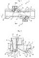
figure 1 est une vue en coupe longitudinale d'un débitmètre selon un premier mode de réalisation de l'invention, - la
figure 2 est une vue en coupe longitudinale d'un dispositif de montage selon le premier mode de réalisation l'invention, - la
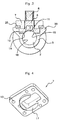
figure 3 est une vue en coupe transversale d'un dispositif de montage et d'un débitmètre selon la ligne AA de lafigure 1 , - la
figure 4 est une vue en perspective de la face inférieure d'une bride d'un dispositif de montage selon le premier mode de réalisation de l'invention, - la
figure 5 est une vue en coupe d'un débitmètre selon le deuxième mode de réalisation de l'invention, équipé de dispositifs de montage adaptés, - la
figure 6 est une vue en perspective d'un dispositif de montage selon le deuxième mode de réalisation de l'invention. - La
figure 1 représente, en coupe longitudinale, un débitmètre 1 comprenant un tube 3 formant une canalisation 2 dans laquelle circule un fluide dont le débit est à mesurer. Dans l'exemple représenté, la canalisation 2 est cylindrique de révolution et comporte un axe longitudinal 4. Le tube 3 comporte deux plateaux 20 (figure3 ) moulés ou usinés sur le tube, diamétralement opposés par rapport à celui-ci et écartés l'un de l'autre selon l'axe longitudinal de la canalisation. Chaque plateau 20 comporte un orifice débouchant dans la canalisation 2. Un dispositif de montage 5 d'un transducteur 9 à ultrasons est installé dans l'orifice de chaque plateau 20 et fixé sur le tube 3. - Le dispositif de montage 5, illustré plus en détail aux
figures 2 et3 , comporte un corps 6 formé d'une seule pièce, moulé de préférence en matière synthétique, par exemple en polyétherimide (PEI) pour sa stabilité en température, dont la forme est au moins pour partie conjuguée de celle de l'orifice pour pouvoir être fixé sur celui-ci. Une fois installé dans l'orifice, le corps 6 présente une surface, dite surface active 15, en contact avec le fluide 19 circulant dans la canalisation. La délimitation entre la surface intérieure 16 de la canalisation et la surface active 15 du corps 6 s'effectue selon une ligne fermée, dite ligne de contour 14. - La surface active 15 est la seule partie du dispositif de montage 5 en contact avec le fluide. Elle s'étend continûment, sans ouverture, sur toute la zone délimitée par la ligne de contour 14.
- Pour éviter des perturbations du fluide 19 à l'interface entre la surface intérieure 16 de la canalisation et la surface active 15 du corps 6 du dispositif de montage, ces deux surfaces sont dans la continuité l'une de l'autre au moins au voisinage de la ligne de contour 14. Ainsi, la surface active 15 est telle que toute tangente à la surface intérieure 16 de la canalisation, le long de la ligne de contour 14 et orthogonale à celle-ci est également tangente à la surface active 15. De cette manière, l'interface entre les deux surfaces est parfaitement lisse et ne peut générer des décrochements de filets de fluide, des turbulences ou encore des zones de stagnation du fluide. Par exemple, pour une canalisation cylindrique, la surface active du corps du dispositif de montage 5 est également cylindrique et de même rayon, au moins au voisinage de la ligne de contour comme montré sur la
figure 3 . - Dans un débitmètre 1 tel qu'illustré à la
figure 1 , deux transducteurs 9 à ultrasons sont installés en vis-à-vis dans la canalisation 2 selon une direction de mesure 12 formant un angle prédéterminé non nul et inférieur à 90° avec l'axe longitudinal 4 dans un plan de symétrie longitudinal de la canalisation. De préférence, l'angle entre la direction de mesure 12 et l'axe longitudinal 4 de la canalisation est de l'ordre de 30° mais peut aller jusqu'à 50° voire plus en fonction des modèles de débitmètre. - Chaque transducteur 9 est formé d'une plaquette de matériau piézoélectrique comportant deux électrodes et protégée par un enrobage externe de matière synthétique de forme parallélépipédique très aplatie. Les faces principales du transducteur sont orthogonales à la direction d'émission / réception des ondes ultrasonores. Chaque transducteur 9 est monté dans un dispositif de montage 5, traversant le tube 3 et débouchant dans la canalisation 2. Les dispositifs de montage 5 sont placés de part et d'autre du tube 3, de manière à ce que les transducteurs 9 soient placés en vis-à-vis et que leur direction d'émission / réception respective coïncide avec la direction de mesure 12.
- Du fait de la continuité de la surface active, le transducteur 9 est isolé du fluide circulant dans la canalisation. Il est donc possible d'utiliser directement une plaquette de matériau piézoélectrique, sans enrobage externe à la place du transducteur 9 enrobé. Comme on le décrira par la suite, la plaquette piézoélectrique peut être fixée dans le corps 6 par une couche de colle ou de résine permettant en partie de réaliser une adaptation d'impédance sonore entre la plaquette piézoélectrique et le fluide. Dès lors, le corps 6 et la plaquette du transducteur forment ensemble au moins une partie d'un transducteur intégré.
- Pour orienter le transducteur 9 selon la direction de mesure, le corps 6 comporte sur sa surface active 15 une niche 10 en creux dont la concavité est orientée vers l'intérieur de la canalisation 2, c'est-à-dire en direction de l'axe longitudinal 4. Cette niche 10 s'étend selon une direction longitudinale parallèle à l'axe longitudinal 4 de la canalisation et comporte au moins une face plane, dite face active 11, orthogonale à la direction de mesure 12. Les autres parois de la niche 10 peuvent avoir une forme quelconque pour autant que ces parois n'interfèrent pas avec les ondes ultrasonores. Par exemple, la niche 10 comporte, comme illustré en détail sur la
figure 2 , une face supérieure parallèle à la direction de mesure 12 et deux faces latérales parallèles au plan de symétrie longitudinal de la canalisation contenant la direction de mesure 12. - Afin d'éviter que la niche 10 forme une source de perturbations du flux de fluide ou de zones de stagnation de celui-ci, tout plan orthogonal à la direction longitudinale de la niche (ou orthogonal à l'axe longitudinal 4 de la canalisation) ne coupe la surface active 15 que selon une seule ligne, c'est-à-dire que le profil de la niche, en coupe longitudinale, ne présente aucun rebroussement ou retour en arrière par rapport au sens de circulation du fluide. En pratique, le profil de la niche ne comporte aucun angle aigu qui pourrait constituer une zone de décrochement des filets de fluide ou une zone morte dans laquelle le fluide serait susceptible de stagner.
- En outre, la surface active 15 et toutes les faces de la niche 10 qui y est ménagée sont reliées entre elles et à la ligne de contour 14 par des surfaces exemptes d'arêtes vives. Par exemple, toutes les surfaces planes sont reliées entre elles par des congés de rayon suffisant pour ne pas créer de turbulences dans les filets de fluide. Par exemple, pour une niche de 10 à 15 mm de profondeur, les rayons des congés sont de l'ordre de 0,5 à 1 mm.
- Cependant, dans certains cas, le flux de fluide peut varier de manière très importante, entrainant des transitions entre divers régimes, par exemple d'un régime laminaire à un régime turbulent en fonction du débit de fluide. Il est alors utile de prévoir certains reliefs à des emplacements prédéterminés de la surface active 15, par exemple au voisinage de la face active 11, afin de gérer les perturbations liées à ces changements de régime. Ainsi, des striures parallèles à la direction de l'écoulement du fluide peuvent être ménagées à la jonction entre la face active 11 et la surface active 15 en amont de la face active par rapport à l'écoulement du fluide, afin de régulariser la direction des filets de fluide. D'autres formes géométriques, par exemple des ailerons, peuvent être employées à divers endroits de la surface active afin de corriger des anomalies dans le flux de fluide sous certains régimes. Ces formes peuvent être avantageusement formées lors du moulage du corps 6.
- À l'opposé de la niche 10, le corps 6 comporte un logement 23, ouvert vers l'extérieur, c'est à dire dont la concavité est orientée à l'opposé de l'axe 4. Ce logement comporte une face plane dite face d'appui 21 parallèle à la face active 11 de la niche 10 et délimitant avec elle une cloison 24 sur laquelle le transducteur 9 est fixé. Le logement 23 reçoit un obturateur 8 de forme adaptée pour remplir sensiblement le logement 23, l'obturateur 8 comportant une face venant plaquer le transducteur 9 sur la face d'appui 21. L'obturateur 8 est fixé dans le logement 23 du corps 6 par tout moyen de fixation adapté, par exemple par vissage, encliquetage, soudure, collage ou bouterollage. L'obturateur 8 est réalisé en matière synthétique, de préférence identique ou compatible avec celle du corps 6, et comporte un ou des alvéoles 22 adaptés pour recevoir des moyens de contact électrique avec le transducteur 9, telles que des broches 18 de connecteur qui traversent l'obturateur et viennent en contact avec les broches du transducteur 9. Lorsque le transducteur 9 est simplement une plaquette piézoélectrique nue, cette plaquette est collée sur la face d'appui 21 par de la colle ou une résine appropriée (pour l'adaptation d'impédance sonore) et plaquée contre cette face d'appui par l'obturateur 8 qui forme un connecteur. Dès lors, le corps 6, la plaquette piézoélectrique et l'obturateur forment un bloc solidaire considéré comme un transducteur intégré.
- Le corps 6 comporte en outre un rebord 25 adapté pour venir en appui sur le plateau 20 tout autour de l'orifice ménagé dans ce plateau. Le rebord 25 comporte sur sa périphérie une gorge adaptée pour recevoir un joint d'étanchéité 26 entre le rebord 25 et le plateau 20.
- Avantageusement, l'orientation du transducteur 9 dans la direction de mesure 12 est assurée par l'inclinaison de la cloison 24 et des faces d'appui 21 et active 11. Dès lors, il est possible de choisir d'insérer le dispositif de montage 5 et donc le corps 6 dans le tube 3 selon une direction quelconque. Préférentiellement, le dispositif de montage 5 est adapté pour être monté sur le tube 3 selon une direction radiale par rapport à celui-ci, c'est-à-dire orthogonalement à l'axe longitudinal 4. Dès lors, le rebord 25 et le plateau 20 peuvent être parallèles et orthogonaux à la direction de montage ce qui simplifie l'usinage de l'orifice de montage dans le tube 3 ainsi que les opérations d'assemblage.
- Le dispositif de montage 5 comporte enfin une bride 7 permettant de fixer le corps 6 sur le plateau 20 au moyen de vis (non représentées) passant dans des alésages 13. La bride 7 comporte une lumière centrale permettant le passage de la partie haute du corps 6 afin que l'obturateur 8 et les connexions 18 soient accessibles de l'extérieur une fois le dispositif de montage 5 en position sur le tube 3. La
figure 4 représente une vue de dessous en perspective de la bride 7 montrant la présence d'un étrier 17 en saillie sur la face inférieure de la bride 7 et adapté pour coopérer avec un profil conjugué ménagé dans le corps 6 afin de faciliter l'orientation de celui-ci dans l'axe du tube 3 et de renforcer la rigidité du corps 6, particulièrement dans le cas où le fluide circulant dans la canalisation est sous forte pression. La bride 7 peut être réalisée en matériau synthétique, éventuellement chargé avec des fibres de verre ou de carbone pour en améliorer la rigidité ou bien encore en métal, préférentiellement en acier inoxydable. Bien entendu, la bride 7 peut également être solidaire du corps 6, par exemple moulée simultanément en une seule pièce. - On se réfère maintenant aux
figures 5 et 6 qui illustrent un deuxième mode de réalisation d'un débitmètre selon l'invention. Le débitmètre 30 se présente sous la forme générale d'un tube 33 terminé aux deux extrémités par des raccords filetés 43. Entre les raccords 43, la canalisation 32 est parcourue par un fluide 34 et comporte trois tronçons tubulaires séparés par deux chambres 31 de tranquillisation situées de part et d'autre du tronçon tubulaire central. Deux transducteurs 39 à ultrasons sont placés en vis-à-vis l'un de l'autre, de part et d'autre du tronçon tubulaire central, sur un axe longitudinal 44 de la canalisation 32, à l'intérieur des chambres 31. - Dans l'exemple représenté, chaque chambre 31 présente un profil en forme de deux troncs de cône séparés par un tronçon de cylindre, ces trois parties étant coaxiales entre elles et avec l'axe longitudinal 44 des tronçons tubulaires. La petite base de chaque tronc de cône présente un diamètre égal au diamètre de la canalisation et la grande base de chaque tronc de cône présente un diamètre égal à celui du tronçon de cylindre. Une telle forme de canalisation serait très difficile, voire impossible à obtenir sans prévoir une partie démontable. Il en va de même par exemple pour une chambre de forme sphérique ou quasi sphérique.
- Afin de faciliter, voire de rendre possible la réalisation d'un débitmètre de ce type, chaque chambre 31 est formée en deux parties, une première partie obtenue à partir du tube 33 et une deuxième partie formée à partir du corps 40 d'un dispositif de montage 35 du transducteur 39. Les deux parties de la chambre 31 se rejoignent selon une ligne de contour 36. Afin de minimiser la génération de turbulences dans le flux du fluide 34 au voisinage de cette ligne de contour, la surface interne de la partie de la chambre 31 issue du tube 33 et la surface, dite surface active 38 de la partie de la chambre issue du dispositif de montage 35, en contact avec le fluide sont telles que le long de la ligne de contour 36, une droite tangente à l'une des surfaces, orthogonale à la ligne de contour est également tangente à l'autre surface. Ainsi, la surface active 38 du dispositif de montage 35 forme une continuité de surface avec le tube 33 pour former la chambre de tranquillisation.
- De préférence, dans la chambre 31, la surface active 38 forme une calotte symétrique de la surface intérieure du tube 33 et la ligne de contour 36 appartient au moins en partie au plan de symétrie passant par l'axe longitudinal 44 de la canalisation 32. La chambre 31 de tranquillisation est ainsi formée de deux demi-coques de taille sensiblement identique.
- Le dispositif de montage 35 comprend également dans sa surface active, une enveloppe creuse, dite plongeur 37, de forme généralement cylindrique et d'axe orthogonal à l'axe longitudinal 44 de la canalisation. Ce plongeur 37 comporte une ouverture axiale vers l'extérieur de la canalisation 32 adaptée pour permettre l'insertion et la fixation d'un transducteur 39 de telle sorte que la direction d'émission / réception de ce transducteur coïncide avec l'axe longitudinal de la canalisation. À cette fin, le plongeur 37 comporte, au moins sur sa surface interne, un méplat 41 orthogonal à l'axe longitudinal de la canalisation. De préférence, le méplat 41 est formé sur les surfaces interne et externe du plongeur. Le transducteur 39 peut alors être fixé, par exemple par collage, sur la face interne du méplat 41, à l'abri du fluide. L'intérieur du plongeur peut ensuite être obturé par coulage d'une résine. Alternativement, le transducteur 39 peut être fixé sur un obturateur (non représenté) de forme conjuguée à celle de l'intérieur du plongeur, cet obturateur étant ensuite inséré dans le plongeur 37.
- Le corps 40 du dispositif de montage 35 présente une surface extérieure sensiblement cylindrique, d'axe orthogonal à l'axe longitudinal 44 de la canalisation et de diamètre adapté pour coopérer avec un orifice de montage ménagé dans le tube 33. Il est ainsi possible d'insérer radialement le dispositif de montage 35 dans le tube 32.
- Le corps 40 est en outre surmonté d'une bride 42 adaptée pour fixer le dispositif de montage 35 sur le tube 32. La bride 42 comporte, à la périphérie du corps 40 une gorge 45 adaptée pour recevoir un joint d'étanchéité.
- Avantageusement, le dispositif de montage 35 est réalisé d'une seule pièce par moulage en matière synthétique, ce qui permet une fabrication précise et particulièrement économique.
- Le débitmètre 30 peut être ainsi constitué d'un tube 33 et de deux dispositifs de montage 35 identiques, équipés chacun d'un transducteur 39 et montés en vis-à-vis de part et d'autre d'un tronçon tubulaire central de la canalisation, chaque dispositif de montage 35 complétant le tube 33 pour former une chambre de tranquillisation 31.
- Bien entendu, cette description est donnée à titre d'exemple illustratif uniquement et l'homme du métier pourra y apporter de nombreuses modifications sans sortir de la portée de l'invention, comme par exemple, dans le premier mode de réalisation, remplacer la niche 10 par une saillie dans le flux de fluide ou prévoir de monter le transducteur 9 dans une saillie sur la face active 11, cette saillie restant dans le volume de la niche 10, ou encore, dans le second mode de réalisation, prévoir de mouler les deux dispositifs de montage 35 en une seule pièce.
Claims (20)
- Dispositif de montage (5, 35) d'un transducteur (9, 39) à ultrasons adapté pour le montage dudit transducteur au travers d'une paroi d'un débitmètre (1,30) comportant une canalisation (2, 32) à l'intérieur de laquelle circule un fluide (19, 34), ledit dispositif comportant un corps (6, 40) adapté pour déboucher sur une surface intérieure (16, 46) de ladite canalisation par un orifice selon une ligne de contour (14, 36) formant une interface entre ladite surface intérieure de la canalisation et une surface du corps, cette interface étant telle que toute droite, orthogonale à la ligne de contour et tangente à la surface intérieure de la canalisation en un point de la ligne de contour est également tangente à ladite surface du corps en ce point, caractérisé en ce que le dispositif présente une surface, dite surface active, en contact avec le fluide circulant dans la canalisation, en ce que cette surface active :- est formée par ladite surface du corps (6, 40) en contact avec le fluide circulant dans la canalisation,- s'étend continûment, sans trou, coupure, ouverture ou discontinuité,et en ce que le transducteur est monté dans le corps (6, 40) en étant isolé du fluide circulant dans la canalisation du fait de la continuité de la surface active.
- Dispositif selon la revendication 1, caractérisé en ce que ladite surface active est au moins partiellement formée par une paroi du corps présentant à l'opposé de la surface active une face d'appui portant le transducteur.
- Dispositif selon l'une quelconque des revendications 1 ou 2, caractérisé en ce que ladite surface active (15) est exempte d'arêtes vives.
- Dispositif selon l'une quelconque des revendications 1 à 3, caractérisé en ce que le transducteur est monté dans le corps de manière à présenter une direction d'émission / réception d'ultrasons traversant une face plane, dite face active, de la surface active.
- Dispositif selon la revendication 4, caractérisé en ce que la face active est parallèle à la face d'appui.
- Dispositif selon l'une quelconque des revendications 4 ou 5, caractérisé en ce qu'il est adapté pour orienter la direction d'émission / réception du transducteur (9) selon une direction, dite direction de mesure (12), adaptée pour s'étendre dans un plan de symétrie longitudinale de la canalisation (2) et former un angle prédéterminé avec un axe longitudinal (4) de celle-ci.
- Dispositif selon l'une quelconque des revendications 1 à 6, caractérisé en ce que ladite surface active comporte une niche en creux s'étendant selon une direction longitudinale adaptée pour être parallèle à un axe longitudinal de la canalisation lorsque le dispositif de montage est monté sur celle-ci.
- Dispositif selon la revendication 7, caractérisé en ce que le profil de la niche est tel que tout plan orthogonal à cette direction longitudinale coupe la surface active en une seule ligne.
- Dispositif selon l'une quelconque des revendications 3 à 8, caractérisé en ce que la surface active comporte, au voisinage de ladite face active, des reliefs adaptés pour modifier un écoulement du fluide.
- Dispositif selon l'une quelconque des revendications 3 à 9 caractérisé en ce que le corps (6) du dispositif comporte au droit de la face d'appui, un logement (23) ouvert présentant une concavité orientée à l'opposé de l'axe longitudinal (4) de la canalisation (2).
- Dispositif selon la revendication 10, caractérisé en ce qu'il comporte en outre un obturateur (8), adapté pour coopérer avec ledit logement (23) afin de plaquer le transducteur (9) à ultrasons contre la face d'appui (21).
- Dispositif selon l'une quelconque des revendications 1 à 11, caractérisé en ce que le dispositif (5) est adapté pour être monté dans la canalisation (2) selon une direction orthogonale à un axe longitudinal (4) de celle-ci.
- Dispositif selon l'une quelconque des revendications 1 à 12, caractérisé en ce qu'il comporte en outre une bride (7) adaptée pour fixer le corps (6) sur ladite canalisation (2), ladite bride comportant en regard du corps une saillie en forme d'étrier (17) adaptée pour coopérer avec une forme conjuguée du corps pour rigidifier ce dernier.
- Dispositif selon l'une quelconque des revendications 1 à 13, caractérisé en ce qu'il est adapté pour être monté sur un débitmètre (30) comportant une canalisation (32) présentant une chambre (31) de tranquillisation à chaque extrémité de celle-ci, chaque chambre comportant un transducteur (39) à ultrasons monté de telle façon que la direction d'émission / réception du transducteur soit confondue avec l'axe longitudinal (44) de ladite canalisation.
- Dispositif selon la revendication 14, caractérisé en ce que la surface active (38) du corps (40) du dispositif (35) forme au moins une partie de la paroi de la chambre (31) de tranquillisation.
- Dispositif selon la revendication 15, caractérisé en ce que la surface active (38) du corps (40) du dispositif forme une calotte dont la ligne de contour (36) est au moins partiellement comprise dans un plan de symétrie de la chambre (31) de tranquillisation passant par l'axe (44) de la canalisation (32).
- Dispositif selon l'une quelconque des revendications 14 à 16, caractérisé en ce que la surface active forme également une enveloppe creuse au moins sensiblement cylindrique, dite plongeur (37), s'étendant radialement en saillie en direction de l'axe longitudinal (44) de la canalisation (32) et d'une longueur adaptée pour couper cet axe.
- Dispositif selon la revendication 17, caractérisé en ce que le plongeur (37) comporte, au moins sur une face interne de l'enveloppe creuse, un méplat (41) orthogonal à l'axe longitudinal (44) de la canalisation (32), adapté pour former une paroi d'appui pour le transducteur (39) à ultrasons.
- Débitmètre (1) à ultrasons, du type comportant une canalisation (2) de mesure du débit d'un fluide (19) et au moins deux transducteurs (9) à ultrasons montés en regard l'un de l'autre au travers d'une paroi de ladite canalisation, dans un même plan longitudinal de symétrie de la canalisation, lesdits transducteurs étant orientés selon une direction de mesure (12) formant un angle non nul et inférieur à 90° avec un axe longitudinal (4) de la canalisation, caractérisé en ce que chaque transducteur (9) est installé dans un dispositif de montage (5) selon l'une quelconque des revendications 1 à 13.
- Débitmètre à ultrasons, du type comportant une canalisation de mesure du débit d'un fluide, ladite canalisation présentant une chambre de tranquillisation à chaque extrémité, chaque chambre comportant un transducteur à ultrasons monté en vis-à-vis du transducteur de l'autre chambre selon un axe longitudinal de ladite canalisation caractérisé en ce que chaque transducteur est installé dans un dispositif de montage selon l'une quelconque des revendications 14 à 18.
Applications Claiming Priority (2)
| Application Number | Priority Date | Filing Date | Title |
|---|---|---|---|
| FR1650565A FR3047068B1 (fr) | 2016-01-25 | 2016-01-25 | Dispositif de montage d'un transducteur a ultrasons et debitmetre equipe d'un tel dispositif |
| PCT/FR2017/050143 WO2017129888A1 (fr) | 2016-01-25 | 2017-01-24 | Dispositif de montage d'un transducteur à ultrasons et débitmètre équipé d'un tel dispositif |
Publications (2)
| Publication Number | Publication Date |
|---|---|
| EP3408622A1 EP3408622A1 (fr) | 2018-12-05 |
| EP3408622B1 true EP3408622B1 (fr) | 2019-11-20 |
Family
ID=55486946
Family Applications (1)
| Application Number | Title | Priority Date | Filing Date |
|---|---|---|---|
| EP17706284.1A Active EP3408622B1 (fr) | 2016-01-25 | 2017-01-24 | Dispositif de montage d'un transducteur à ultrasons et débitmètre équipé d'un tel dispositif |
Country Status (6)
| Country | Link |
|---|---|
| US (1) | US10704940B2 (fr) |
| EP (1) | EP3408622B1 (fr) |
| CN (1) | CN108603776B (fr) |
| ES (1) | ES2770095T3 (fr) |
| FR (1) | FR3047068B1 (fr) |
| WO (1) | WO2017129888A1 (fr) |
Cited By (1)
| Publication number | Priority date | Publication date | Assignee | Title |
|---|---|---|---|---|
| BE1030130A1 (nl) | 2021-12-28 | 2023-07-20 | Smet Gwt Europe | Verbeterde bemaling |
Families Citing this family (10)
| Publication number | Priority date | Publication date | Assignee | Title |
|---|---|---|---|---|
| CN111670342B (zh) * | 2017-12-03 | 2023-11-24 | 尤金·菲力 | 流量计 |
| JP6894863B2 (ja) * | 2018-03-14 | 2021-06-30 | 株式会社キーエンス | クランプオン式超音波流量センサ |
| FR3102304B1 (fr) * | 2019-10-17 | 2021-10-15 | Sagemcom Energy & Telecom Sas | Support de cellule piézoélectrique de transducteur ultrasonore |
| DE102019009033A1 (de) * | 2019-12-31 | 2021-07-01 | Marquardt Gmbh | Baueinheit für eine Fluid-Leitung |
| FR3111696B1 (fr) | 2020-06-19 | 2023-02-10 | Integra Metering Sas | Débitmètre et son procédé de montage |
| FR3111695B1 (fr) | 2020-06-19 | 2023-02-10 | Integra Metering Sas | Débitmètre et son procédé de montage |
| CN112268587B (zh) * | 2020-09-07 | 2022-10-21 | 福建福清核电有限公司 | 一种适用于对角安装的便携式超声波流量计探头夹具 |
| US11906337B2 (en) * | 2021-02-15 | 2024-02-20 | Honeywell International Inc. | Inline transducer housing assembly |
| DE102022210971A1 (de) * | 2022-10-18 | 2024-04-18 | Mib Gmbh Messtechnik Und Industrieberatung | Ultraschallmessanordnung |
| WO2025091055A1 (fr) * | 2023-10-23 | 2025-05-01 | Eugene Fourie | Formation de boîtier |
Family Cites Families (8)
| Publication number | Priority date | Publication date | Assignee | Title |
|---|---|---|---|---|
| US3817098A (en) | 1972-08-09 | 1974-06-18 | Saratoga Systems | Axial fluid flow and sound speed |
| DE3020282C2 (de) * | 1980-05-28 | 1985-08-08 | Siemens AG, 1000 Berlin und 8000 München | Durchfluß-Strömungsmesser mit Ultraschall |
| GB2101318A (en) * | 1981-05-29 | 1983-01-12 | Itt | Ultrasonic flowmeter |
| US4754650A (en) * | 1983-07-29 | 1988-07-05 | Panametrics, Inc. | Apparatus and methods for measuring fluid flow parameters |
| KR960013251B1 (ko) | 1993-08-25 | 1996-10-02 | 주식회사 창민물산 | 초음파 유량측정 방법과 장치 |
| EP0800062A3 (fr) * | 1996-04-04 | 1998-04-15 | Georg Fischer Rohrleitungssysteme AG | Dispositif pour la mesure de la vitesse d'écoulement d'un fluide |
| EP2333495A1 (fr) * | 2009-11-25 | 2011-06-15 | Kamstrup A/S | Débitmètre de consommation à ultrasons doté d'une pièce de connexion |
| PL2888560T3 (pl) * | 2012-08-22 | 2023-08-21 | Apator Miitors Aps | Kompaktowy przepływomierz ultradźwiękowy |
-
2016
- 2016-01-25 FR FR1650565A patent/FR3047068B1/fr active Active
-
2017
- 2017-01-24 EP EP17706284.1A patent/EP3408622B1/fr active Active
- 2017-01-24 CN CN201780008117.6A patent/CN108603776B/zh active Active
- 2017-01-24 WO PCT/FR2017/050143 patent/WO2017129888A1/fr not_active Ceased
- 2017-01-24 US US16/072,419 patent/US10704940B2/en active Active
- 2017-01-24 ES ES17706284T patent/ES2770095T3/es active Active
Non-Patent Citations (1)
| Title |
|---|
| None * |
Cited By (1)
| Publication number | Priority date | Publication date | Assignee | Title |
|---|---|---|---|---|
| BE1030130A1 (nl) | 2021-12-28 | 2023-07-20 | Smet Gwt Europe | Verbeterde bemaling |
Also Published As
| Publication number | Publication date |
|---|---|
| WO2017129888A1 (fr) | 2017-08-03 |
| US10704940B2 (en) | 2020-07-07 |
| FR3047068A1 (fr) | 2017-07-28 |
| US20190033106A1 (en) | 2019-01-31 |
| EP3408622A1 (fr) | 2018-12-05 |
| CN108603776A (zh) | 2018-09-28 |
| CN108603776B (zh) | 2020-12-11 |
| ES2770095T3 (es) | 2020-06-30 |
| FR3047068B1 (fr) | 2019-07-19 |
Similar Documents
| Publication | Publication Date | Title |
|---|---|---|
| FR3047068B1 (fr) | Dispositif de montage d'un transducteur a ultrasons et debitmetre equipe d'un tel dispositif | |
| FR2493461A1 (fr) | Dispositif de vanne a bille | |
| FR3050228A1 (fr) | Dispositif de refroidissement par jets d'air d'un carter de turbine | |
| FR3086388A1 (fr) | Moyen de mesure de fluide presentant un boitier de fluide, et procede de fabrication de boitier de fluide | |
| EP3286529B1 (fr) | Vanne incorporant un débitmètre pour la mesure d'un débit de fluide à l'intérieur de la vanne | |
| EP1975573A1 (fr) | Compteur à cellule de mesure à ultra sons de type capsule, standardisée | |
| WO2011064467A1 (fr) | Composants de garniture de forage et train de composants | |
| EP0750977B1 (fr) | Dispositif d'étanchéité, notamment pour machine de transformation de matière plastique | |
| WO2023061618A1 (fr) | Débitmètre à ultrasons comportant une vanne et procédé de montage d'un tel débitmètre | |
| EP1293760B1 (fr) | Procédé de fabrication d'éléments constitutifs de compteurs de liquide en matière plastique | |
| EP1090245A1 (fr) | Procede de montage d'un raccord a l'extremite d'un tube et nouveau type de raccord permettant sa mise en oeuvre | |
| EP3809404B1 (fr) | Support de cellule piezoelectrique de transducteur ultrasonore | |
| FR3041059A1 (fr) | Mamelon, ajutage, systeme antirotation comportant ledit mamelon et ledit ajutage, turbomachine comportant ledit systeme | |
| WO2016170238A1 (fr) | Dispositif de mesure de vitesse d'écoulement d'un fluide à transducteur(s) ultrasonore(s) | |
| WO2020193437A1 (fr) | Réservoir pour gaz sous pression | |
| FR2715973A1 (fr) | Régulateur de pression interne à l'embase d'un ensemble de puisage. | |
| EP1469288A1 (fr) | Compteur d'eau à chambre de mesure volumétrique | |
| WO2015110507A1 (fr) | Module de captage d'un gaz dissous dans un liquide et dispositif de mesure | |
| EP0068920B1 (fr) | Débitmètre à tourbillon, notamment pour fluides à faible viscosité | |
| FR2586102A1 (fr) | Corps de compteur d'eau a jet unique | |
| FR3104045A1 (fr) | Molette de soudage. | |
| FR2841979A1 (fr) | Corps de compteur de fluide en particulier d'eau | |
| EP3166712A1 (fr) | Embase d'un module de captage d'un gaz dissous dans un liquide et dispositif de mesure | |
| WO2021255397A1 (fr) | Débitmètre et son procédé de montage | |
| EP0828100A1 (fr) | Robinet à obturateur sphérique |
Legal Events
| Date | Code | Title | Description |
|---|---|---|---|
| STAA | Information on the status of an ep patent application or granted ep patent |
Free format text: STATUS: UNKNOWN |
|
| STAA | Information on the status of an ep patent application or granted ep patent |
Free format text: STATUS: THE INTERNATIONAL PUBLICATION HAS BEEN MADE |
|
| PUAI | Public reference made under article 153(3) epc to a published international application that has entered the european phase |
Free format text: ORIGINAL CODE: 0009012 |
|
| STAA | Information on the status of an ep patent application or granted ep patent |
Free format text: STATUS: REQUEST FOR EXAMINATION WAS MADE |
|
| 17P | Request for examination filed |
Effective date: 20180625 |
|
| AK | Designated contracting states |
Kind code of ref document: A1 Designated state(s): AL AT BE BG CH CY CZ DE DK EE ES FI FR GB GR HR HU IE IS IT LI LT LU LV MC MK MT NL NO PL PT RO RS SE SI SK SM TR |
|
| AX | Request for extension of the european patent |
Extension state: BA ME |
|
| DAV | Request for validation of the european patent (deleted) | ||
| DAX | Request for extension of the european patent (deleted) | ||
| GRAP | Despatch of communication of intention to grant a patent |
Free format text: ORIGINAL CODE: EPIDOSNIGR1 |
|
| INTG | Intention to grant announced |
Effective date: 20190614 |
|
| GRAS | Grant fee paid |
Free format text: ORIGINAL CODE: EPIDOSNIGR3 |
|
| STAA | Information on the status of an ep patent application or granted ep patent |
Free format text: STATUS: GRANT OF PATENT IS INTENDED |
|
| GRAA | (expected) grant |
Free format text: ORIGINAL CODE: 0009210 |
|
| STAA | Information on the status of an ep patent application or granted ep patent |
Free format text: STATUS: THE PATENT HAS BEEN GRANTED |
|
| AK | Designated contracting states |
Kind code of ref document: B1 Designated state(s): AL AT BE BG CH CY CZ DE DK EE ES FI FR GB GR HR HU IE IS IT LI LT LU LV MC MK MT NL NO PL PT RO RS SE SI SK SM TR |
|
| REG | Reference to a national code |
Ref country code: GB Ref legal event code: FG4D Free format text: NOT ENGLISH |
|
| REG | Reference to a national code |
Ref country code: CH Ref legal event code: EP |
|
| REG | Reference to a national code |
Ref country code: IE Ref legal event code: FG4D Free format text: LANGUAGE OF EP DOCUMENT: FRENCH |
|
| REG | Reference to a national code |
Ref country code: DE Ref legal event code: R096 Ref document number: 602017008914 Country of ref document: DE |
|
| REG | Reference to a national code |
Ref country code: AT Ref legal event code: REF Ref document number: 1204704 Country of ref document: AT Kind code of ref document: T Effective date: 20191215 |
|
| REG | Reference to a national code |
Ref country code: NL Ref legal event code: MP Effective date: 20191120 |
|
| REG | Reference to a national code |
Ref country code: LT Ref legal event code: MG4D |
|
| PG25 | Lapsed in a contracting state [announced via postgrant information from national office to epo] |
Ref country code: FI Free format text: LAPSE BECAUSE OF FAILURE TO SUBMIT A TRANSLATION OF THE DESCRIPTION OR TO PAY THE FEE WITHIN THE PRESCRIBED TIME-LIMIT Effective date: 20191120 Ref country code: BG Free format text: LAPSE BECAUSE OF FAILURE TO SUBMIT A TRANSLATION OF THE DESCRIPTION OR TO PAY THE FEE WITHIN THE PRESCRIBED TIME-LIMIT Effective date: 20200220 Ref country code: NO Free format text: LAPSE BECAUSE OF FAILURE TO SUBMIT A TRANSLATION OF THE DESCRIPTION OR TO PAY THE FEE WITHIN THE PRESCRIBED TIME-LIMIT Effective date: 20200220 Ref country code: GR Free format text: LAPSE BECAUSE OF FAILURE TO SUBMIT A TRANSLATION OF THE DESCRIPTION OR TO PAY THE FEE WITHIN THE PRESCRIBED TIME-LIMIT Effective date: 20200221 Ref country code: LV Free format text: LAPSE BECAUSE OF FAILURE TO SUBMIT A TRANSLATION OF THE DESCRIPTION OR TO PAY THE FEE WITHIN THE PRESCRIBED TIME-LIMIT Effective date: 20191120 Ref country code: SE Free format text: LAPSE BECAUSE OF FAILURE TO SUBMIT A TRANSLATION OF THE DESCRIPTION OR TO PAY THE FEE WITHIN THE PRESCRIBED TIME-LIMIT Effective date: 20191120 Ref country code: NL Free format text: LAPSE BECAUSE OF FAILURE TO SUBMIT A TRANSLATION OF THE DESCRIPTION OR TO PAY THE FEE WITHIN THE PRESCRIBED TIME-LIMIT Effective date: 20191120 Ref country code: LT Free format text: LAPSE BECAUSE OF FAILURE TO SUBMIT A TRANSLATION OF THE DESCRIPTION OR TO PAY THE FEE WITHIN THE PRESCRIBED TIME-LIMIT Effective date: 20191120 |
|
| PG25 | Lapsed in a contracting state [announced via postgrant information from national office to epo] |
Ref country code: HR Free format text: LAPSE BECAUSE OF FAILURE TO SUBMIT A TRANSLATION OF THE DESCRIPTION OR TO PAY THE FEE WITHIN THE PRESCRIBED TIME-LIMIT Effective date: 20191120 Ref country code: IS Free format text: LAPSE BECAUSE OF FAILURE TO SUBMIT A TRANSLATION OF THE DESCRIPTION OR TO PAY THE FEE WITHIN THE PRESCRIBED TIME-LIMIT Effective date: 20200320 Ref country code: RS Free format text: LAPSE BECAUSE OF FAILURE TO SUBMIT A TRANSLATION OF THE DESCRIPTION OR TO PAY THE FEE WITHIN THE PRESCRIBED TIME-LIMIT Effective date: 20191120 |
|
| PG25 | Lapsed in a contracting state [announced via postgrant information from national office to epo] |
Ref country code: AL Free format text: LAPSE BECAUSE OF FAILURE TO SUBMIT A TRANSLATION OF THE DESCRIPTION OR TO PAY THE FEE WITHIN THE PRESCRIBED TIME-LIMIT Effective date: 20191120 |
|
| REG | Reference to a national code |
Ref country code: ES Ref legal event code: FG2A Ref document number: 2770095 Country of ref document: ES Kind code of ref document: T3 Effective date: 20200630 |
|
| PG25 | Lapsed in a contracting state [announced via postgrant information from national office to epo] |
Ref country code: RO Free format text: LAPSE BECAUSE OF FAILURE TO SUBMIT A TRANSLATION OF THE DESCRIPTION OR TO PAY THE FEE WITHIN THE PRESCRIBED TIME-LIMIT Effective date: 20191120 Ref country code: CZ Free format text: LAPSE BECAUSE OF FAILURE TO SUBMIT A TRANSLATION OF THE DESCRIPTION OR TO PAY THE FEE WITHIN THE PRESCRIBED TIME-LIMIT Effective date: 20191120 Ref country code: DK Free format text: LAPSE BECAUSE OF FAILURE TO SUBMIT A TRANSLATION OF THE DESCRIPTION OR TO PAY THE FEE WITHIN THE PRESCRIBED TIME-LIMIT Effective date: 20191120 Ref country code: PT Free format text: LAPSE BECAUSE OF FAILURE TO SUBMIT A TRANSLATION OF THE DESCRIPTION OR TO PAY THE FEE WITHIN THE PRESCRIBED TIME-LIMIT Effective date: 20200412 Ref country code: EE Free format text: LAPSE BECAUSE OF FAILURE TO SUBMIT A TRANSLATION OF THE DESCRIPTION OR TO PAY THE FEE WITHIN THE PRESCRIBED TIME-LIMIT Effective date: 20191120 |
|
| REG | Reference to a national code |
Ref country code: AT Ref legal event code: MK05 Ref document number: 1204704 Country of ref document: AT Kind code of ref document: T Effective date: 20191120 |
|
| REG | Reference to a national code |
Ref country code: DE Ref legal event code: R097 Ref document number: 602017008914 Country of ref document: DE |
|
| PG25 | Lapsed in a contracting state [announced via postgrant information from national office to epo] |
Ref country code: SK Free format text: LAPSE BECAUSE OF FAILURE TO SUBMIT A TRANSLATION OF THE DESCRIPTION OR TO PAY THE FEE WITHIN THE PRESCRIBED TIME-LIMIT Effective date: 20191120 Ref country code: MC Free format text: LAPSE BECAUSE OF FAILURE TO SUBMIT A TRANSLATION OF THE DESCRIPTION OR TO PAY THE FEE WITHIN THE PRESCRIBED TIME-LIMIT Effective date: 20191120 Ref country code: SM Free format text: LAPSE BECAUSE OF FAILURE TO SUBMIT A TRANSLATION OF THE DESCRIPTION OR TO PAY THE FEE WITHIN THE PRESCRIBED TIME-LIMIT Effective date: 20191120 |
|
| PLBE | No opposition filed within time limit |
Free format text: ORIGINAL CODE: 0009261 |
|
| STAA | Information on the status of an ep patent application or granted ep patent |
Free format text: STATUS: NO OPPOSITION FILED WITHIN TIME LIMIT |
|
| REG | Reference to a national code |
Ref country code: BE Ref legal event code: MM Effective date: 20200131 |
|
| 26N | No opposition filed |
Effective date: 20200821 |
|
| PG25 | Lapsed in a contracting state [announced via postgrant information from national office to epo] |
Ref country code: LU Free format text: LAPSE BECAUSE OF NON-PAYMENT OF DUE FEES Effective date: 20200124 |
|
| PG25 | Lapsed in a contracting state [announced via postgrant information from national office to epo] |
Ref country code: AT Free format text: LAPSE BECAUSE OF FAILURE TO SUBMIT A TRANSLATION OF THE DESCRIPTION OR TO PAY THE FEE WITHIN THE PRESCRIBED TIME-LIMIT Effective date: 20191120 Ref country code: SI Free format text: LAPSE BECAUSE OF FAILURE TO SUBMIT A TRANSLATION OF THE DESCRIPTION OR TO PAY THE FEE WITHIN THE PRESCRIBED TIME-LIMIT Effective date: 20191120 Ref country code: PL Free format text: LAPSE BECAUSE OF FAILURE TO SUBMIT A TRANSLATION OF THE DESCRIPTION OR TO PAY THE FEE WITHIN THE PRESCRIBED TIME-LIMIT Effective date: 20191120 Ref country code: BE Free format text: LAPSE BECAUSE OF NON-PAYMENT OF DUE FEES Effective date: 20200131 |
|
| PG25 | Lapsed in a contracting state [announced via postgrant information from national office to epo] |
Ref country code: IE Free format text: LAPSE BECAUSE OF NON-PAYMENT OF DUE FEES Effective date: 20200124 |
|
| GBPC | Gb: european patent ceased through non-payment of renewal fee |
Effective date: 20210124 |
|
| PG25 | Lapsed in a contracting state [announced via postgrant information from national office to epo] |
Ref country code: GB Free format text: LAPSE BECAUSE OF NON-PAYMENT OF DUE FEES Effective date: 20210124 |
|
| PG25 | Lapsed in a contracting state [announced via postgrant information from national office to epo] |
Ref country code: TR Free format text: LAPSE BECAUSE OF FAILURE TO SUBMIT A TRANSLATION OF THE DESCRIPTION OR TO PAY THE FEE WITHIN THE PRESCRIBED TIME-LIMIT Effective date: 20191120 Ref country code: MT Free format text: LAPSE BECAUSE OF FAILURE TO SUBMIT A TRANSLATION OF THE DESCRIPTION OR TO PAY THE FEE WITHIN THE PRESCRIBED TIME-LIMIT Effective date: 20191120 Ref country code: CY Free format text: LAPSE BECAUSE OF FAILURE TO SUBMIT A TRANSLATION OF THE DESCRIPTION OR TO PAY THE FEE WITHIN THE PRESCRIBED TIME-LIMIT Effective date: 20191120 |
|
| PG25 | Lapsed in a contracting state [announced via postgrant information from national office to epo] |
Ref country code: MK Free format text: LAPSE BECAUSE OF FAILURE TO SUBMIT A TRANSLATION OF THE DESCRIPTION OR TO PAY THE FEE WITHIN THE PRESCRIBED TIME-LIMIT Effective date: 20191120 |
|
| GRAP | Despatch of communication of intention to grant a patent |
Free format text: ORIGINAL CODE: EPIDOSNIGR1 |
|
| REG | Reference to a national code |
Ref country code: DE Ref legal event code: R081 Ref document number: 602017008914 Country of ref document: DE Owner name: INTEGRA METERING AG, CH Free format text: FORMER OWNER: INTEGRA METERING SAS, BLAGNAC, FR Ref country code: DE Ref legal event code: R082 Ref document number: 602017008914 Country of ref document: DE Representative=s name: IPSILON PATENTANWALTSGESELLSCHAFT MBH, DE |
|
| REG | Reference to a national code |
Ref country code: ES Ref legal event code: PC2A Owner name: INTEGRA METERING AG Effective date: 20230220 |
|
| P01 | Opt-out of the competence of the unified patent court (upc) registered |
Effective date: 20230530 |
|
| REG | Reference to a national code |
Ref country code: CH Ref legal event code: R14 Free format text: ST27 STATUS EVENT CODE: U-0-0-R10-R14 (AS PROVIDED BY THE NATIONAL OFFICE) Effective date: 20251223 |
|
| REG | Reference to a national code |
Ref country code: CH Ref legal event code: U11 Free format text: ST27 STATUS EVENT CODE: U-0-0-U10-U11 (AS PROVIDED BY THE NATIONAL OFFICE) Effective date: 20260201 |
|
| PGFP | Annual fee paid to national office [announced via postgrant information from national office to epo] |
Ref country code: ES Payment date: 20260227 Year of fee payment: 10 |
|
| PGFP | Annual fee paid to national office [announced via postgrant information from national office to epo] |
Ref country code: DE Payment date: 20260121 Year of fee payment: 10 |
|
| PGFP | Annual fee paid to national office [announced via postgrant information from national office to epo] |
Ref country code: IT Payment date: 20260121 Year of fee payment: 10 |
|
| PGFP | Annual fee paid to national office [announced via postgrant information from national office to epo] |
Ref country code: FR Payment date: 20260123 Year of fee payment: 10 |
|
| PGFP | Annual fee paid to national office [announced via postgrant information from national office to epo] |
Ref country code: CH Payment date: 20260201 Year of fee payment: 10 |