EP3408472B1 - Foldable structure - Google Patents
Foldable structure Download PDFInfo
- Publication number
- EP3408472B1 EP3408472B1 EP17743515.3A EP17743515A EP3408472B1 EP 3408472 B1 EP3408472 B1 EP 3408472B1 EP 17743515 A EP17743515 A EP 17743515A EP 3408472 B1 EP3408472 B1 EP 3408472B1
- Authority
- EP
- European Patent Office
- Prior art keywords
- chord
- bracket
- frame
- peak
- pin
- Prior art date
- Legal status (The legal status is an assumption and is not a legal conclusion. Google has not performed a legal analysis and makes no representation as to the accuracy of the status listed.)
- Active
Links
Images




















Classifications
-
- E—FIXED CONSTRUCTIONS
- E04—BUILDING
- E04H—BUILDINGS OR LIKE STRUCTURES FOR PARTICULAR PURPOSES; SWIMMING OR SPLASH BATHS OR POOLS; MASTS; FENCING; TENTS OR CANOPIES, IN GENERAL
- E04H15/00—Tents or canopies, in general
- E04H15/32—Parts, components, construction details, accessories, interior equipment, specially adapted for tents, e.g. guy-line equipment, skirts, thresholds
- E04H15/34—Supporting means, e.g. frames
- E04H15/44—Supporting means, e.g. frames collapsible, e.g. breakdown type
- E04H15/48—Supporting means, e.g. frames collapsible, e.g. breakdown type foldable, i.e. having pivoted or hinged means
-
- E—FIXED CONSTRUCTIONS
- E04—BUILDING
- E04H—BUILDINGS OR LIKE STRUCTURES FOR PARTICULAR PURPOSES; SWIMMING OR SPLASH BATHS OR POOLS; MASTS; FENCING; TENTS OR CANOPIES, IN GENERAL
- E04H15/00—Tents or canopies, in general
- E04H15/18—Tents having plural sectional covers, e.g. pavilions, vaulted tents, marquees, circus tents; Plural tents, e.g. modular
-
- E—FIXED CONSTRUCTIONS
- E04—BUILDING
- E04H—BUILDINGS OR LIKE STRUCTURES FOR PARTICULAR PURPOSES; SWIMMING OR SPLASH BATHS OR POOLS; MASTS; FENCING; TENTS OR CANOPIES, IN GENERAL
- E04H15/00—Tents or canopies, in general
- E04H15/32—Parts, components, construction details, accessories, interior equipment, specially adapted for tents, e.g. guy-line equipment, skirts, thresholds
- E04H15/34—Supporting means, e.g. frames
- E04H15/44—Supporting means, e.g. frames collapsible, e.g. breakdown type
-
- E—FIXED CONSTRUCTIONS
- E04—BUILDING
- E04H—BUILDINGS OR LIKE STRUCTURES FOR PARTICULAR PURPOSES; SWIMMING OR SPLASH BATHS OR POOLS; MASTS; FENCING; TENTS OR CANOPIES, IN GENERAL
- E04H15/00—Tents or canopies, in general
- E04H15/32—Parts, components, construction details, accessories, interior equipment, specially adapted for tents, e.g. guy-line equipment, skirts, thresholds
- E04H15/34—Supporting means, e.g. frames
- E04H15/36—Supporting means, e.g. frames arch-shaped type
Definitions
- the invention relates to the field of collapsible structures, in particular fabriccovered structures such as tents and collapsible frames for supporting same.
- Such structures have use in military applications, for resource exploration, for large public events such as concerts and festivals and the like.
- the frames for such structures consist of multiple separate pieces which can become misplaced and are complicated to assemble, dis-assemble and pack for shipment. There is therefore a need for more simple and efficient frames for large-scale collapsible structures.
- CN 201169955Y discloses connecting pieces of an automatic foldable tent rack
- GB 982411A , US1291947A and US608247A disclose collapsible tent frames.
- the present invention therefore provides a folding tent frame component according to claim 1 and a method according to claim 5 of assembling and disassembling a tent frame.
- a modular shelter system comprising a number of folding frame elements which is rapidly deployable, is also disclosed.
- the folding elements incorporate joints with self-resetting lock mechanisms. During set up they automatically lock the joints into place and once unlocked they reset to automatically lock the joints into place on the next setup.
- Certain joint locks contain a further feature which allows joints to be set into an unlocked position until the joint is bent, at which time the lock resets, ready to lock the joint into position on the next setup.
- the system may use a quick release foot designed to allow a special high wind set up and tear down procedure, where the feet are removed from the legs before setup, attached to the shelter's floor, and securely anchored to the ground.
- the legs snap into the pre-anchored feet.
- the feet can be released from the leg assembly by the user's foot to allow both hands to grasp on the leg at all times.
- a folding tent frame component comprising:
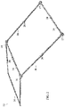
- FIG. 1 an unfolded frame assembly 10 for a one bay structure according to an embodiment of the invention is shown.
- Unfolded frame assemblies 100 and 200 for two and four bay structures according to an embodiment of the invention are shown in Fig. 34 and 35 .
- Each frame assembly 10 comprises an upper section assembly 12 ( Fig. 2 ) which includes fully attached folding purlins 14.
- Frame assembly 10 also comprises peak brackets 16, eave brackets 17, chords 18, legs 20, wind kit posts 22, midspan chords 24, chord knee joints 26, purlin knee joints 28, and leg knee joints 30.
- Such joints contain self-resetting lock mechanisms as described below. During set up they lock the joints into place without needing to be touched. Once unlocked they reset to automatically lock the joints into place on the next setup.
- Peak bracket and chord joint locks contain a secondary feature which allows joints to be set into an unlocked position until the joint is bent, at which time the lock resets, ready to lock the joint into position on the next setup. This facilitates the pack up procedure, as multiple joint locks need not be manually held unlocked at the same time.
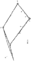
- FIG. 3 shows the upper folding assembly 12 for the frame as shown in Fig. 1 and 2 , folded for packing.
- Fig. 4 one set of two folded chords 18 and one folded purlin 14 are rotated about the hinged peak bracket 16 to separate from the set of two folded chords 18 and two folded purlin 14.
- Fig. 5 the chords 18 are unfolded by rotating at chord knee joints 26.
- Fig. 6 the partially unfolded upper frame assembly is placed in an upright position and as shown in Fig. 7 purlins 14 are unfolded about hinged purlin knee joints 28, to reach the unfolded configuration shown in Fig. 8 .
- Peak brackets 16 are hingedly connected to chord 18 about axis 30.
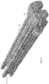
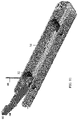
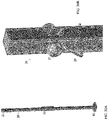
- the chord 18 When in the unfolded position shown in Fig. 9 and 10 , the chord 18 is locked in place by pins 32 which are mounted on interior sliding locking frame 34 and extend through slots 36 in the sides of chords 18, and into slots 38. Pins 32 are biased by spring 40 into the locked position shown in Fig. 9 . Pulling on cable 42 slides sub-frame 34 away from the peak bracket 16, releasing pin 32 from slot 38 and allowing chord 18 to rotate.
- peak bracket joints, chord knee joints, purlin knee joints, and leg knee joints all contain self-resetting lock mechanisms. During set up they lock the joints into place without needing to be touched. Once unlocked they reset to automatically lock the joints into place on the next setup.
- lockout bars 44 permit the chords 18 to be kept in an extended unfolded position without locking.
- lockout bar 44 is hingedly mounted on pin 32 on sliding locking frame 34. It is biased to an upward position by spring 48. Head 46 is sized to move upwardly into slot 50 of chord knee joint 26 or slot 52 of peak bracket 16.
- the operator can unlock the joint by allowing head 46 to extend into slot 50/52 to prevent the joint from re-locking while keeping the joint unfolded. Once the joint is bent, head 46 comes out of slot 50/52 at which time the lock resets, ready to lock the joint into position on the next setup.
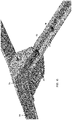
- Chord knee bracket shown in Fig. 12 and 13 operates in the same way as the peak bracket 16 using sliding locking frame 34.
- Purlin knee joints 28, and leg knee joints 30 operate in the same manner as the chord knee bracket 26 and the peak bracket 16 without the secondary lockout feature.
- Purlin knee bracket 28 is shown in Fig. 14 .
- Purlin sections 60, 62 are hingedly connected about axis 64. When in the unfolded position shown in Fig. 14 and 15 , the purlin sections 60, 62 are locked in place by pins 66 which are mounted on interior sliding locking frame 68 and extend through slots 70 in the sides of the purlins, and into slots 72. Pins 66 are biased by spring 67 into the locked position shown in Fig. 14 . Pulling on cable 69 slides locking frame 68, releasing pins 66 from slot 72 and allowing purlin sections 60, 62 to rotate.
- Eave brackets 17 receive the upper end 21 of legs 20 through apertures 23.
- the lower surface 25 of bracket 17 rests on upper leg bosses 27 when the legs are in place.
- leg 20 may be provided with close haul wire j-hook 29 for cover connection.
- leg knee joints 30 operate in the same manner as the chord knee bracket 26 and the peak bracket 16 without the secondary lockout feature.
- Leg knee joint 30 is shown in Fig. 21A and 21B .
- Leg sections 31, 33 are hingedly connected about axis 35. When in the unfolded position shown in Fig. 21A and 21B , leg sections 31, 33 are locked in place by pins 37 which are mounted on interior sliding locking frame 39 and extend through slots 41 in the sides of the legs 20, and into slots 43.
- Pins 37 are biased by spring 45 into the locked position shown in Fig. 21A . Pulling on boss 47 slides locking frame 39, releasing pins 37 from slot 43 and allowing leg sections 31, 33 to rotate. This lock mechanism allows for a two-handed grip when lowering the shelter.
- Fig. 22 and 23 show a quick release foot assembly 80 for attachment to legs 20.
- Such quick release feet allow a high wind set up and tear down procedure, where the feet 80 are removed from the legs 20 before setup, attached to the shelter's floor and securely anchored to the ground through apertures 84.
- horizontal cylindrical extensions (not shown) on the legs 20 snap into slots 86 in the pre-anchored feet 80 to be held in place by spring-biased hinged arms 83, greatly reducing the risk of injury to personnel or damage to equipment.
- High wind take down is the opposite of set up, where the shelter feet can be released from the leg assembly by using a foot to force open arms 83, which allows a steady two-handed grasp on the leg at all times.
- Foot pads 80 are also sized to allow a low enough ground pressure, even with a snow loaded shelter, such that any ground capable of supporting a walking individual, or a vehicle driving on normal tires, is sufficient to support the shelter.
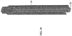
- Midspan chords 24 are shown in Fig. 24 through 28 .
- Each chord 24 comprises a single folding element which, when unfolded as shown in Fig. 24 , rests on upper frame assembly 12, with its central hinge 25 on peak purlin bracket 28 and its ends on lower purlin brackets 28.
- the midspan chord knee joints 27 fold and lock/unlock the chord sections 91, 93, 95, 97 in the same manner as the purlin knee joints 28, using cable 29 to unlock the joint.
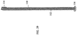
- a telescoping wind kit post 110 is illustrated in Fig. 29 through 33 .
- Such posts can be attached to chords 18 at either end of the frame 10, in order to assist in securing the cover to the structure, as follows.
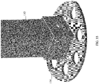
- Each post 110 has a telescoping vertical post 112, the interior telescopic section being secured at its lower end to wind kit post foot 116.
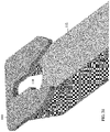
- the post 112 is provided with a bracket 113 having a keyhole slot 118 which engages a bolt 120 on chord 18.
- the size of the modular structure can be increased by increasing the number of chords 18, purlins 14 and peak brackets 16 in the upper frame assembly 12, with proportionate increase in the number of legs 20 and midspan chords 24.
- the resulting structure may thereby accommodate a two or four bays for equipment storage.
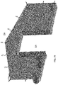
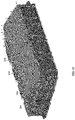
- Fig. 36 illustrates a completed fabric cover 220 for the one bay structure whose frame 10 is shown in Fig. 1 . It includes an endwall 222 shown in Fig. 37 , a barrel section 224 shown in Fig. 38 , and a second endwall 226 shown in Fig. 39 .
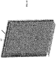
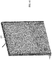
- a soft door assembly 227 may be used for doors 228, whose exterior is shown in Fig. 40 and interior in Fig. 41 .
- two barrel sections 224 are used and four are used for the four bay structure shown in Fig. 43 .
- Insulation 240 can be added to the structure as shown in Fig. 44 for a single bay structure. It comprises two insulation endwalls 242 for the removable insulation package shown in Fig. 45 , both endwalls being the same.
- the barrel 244 for the removable insulation package is shown in Fig. 46 . Again for the two bay structure as shown in Fig. 47 , two barrel sections 244 are used and four are used for the four bay structure shown in Fig. 48 .
- Fig. 49 illustrates a solar shade 250 for use with the one bay shelter shown in Fig. 36
- Fig. 50 illustrates a winter fly 252 for use with the one-bay shelter.
- Both assemblies are tensioned just at the gable ends with a parabolically curved wire rope which is anchored to the feet on the corner legs. This wire rope acts similarly to the main support cable in a tension bridge, only inverted. This makes fitment and proper tensioning simpler.
- the fabric cover 220 can be attached after the frame has been erected.
- Fabric cover 220 may be attached to the frame elements using fasteners such as hooks or hook and loop fasteners and in particular close haul j-hooks 29 at the eaves as previously noted above.
- Fabric dry bag style port closures are preferred.
- PALS Pouch Attachment Ladder System
- Modular Lightweight Load-carrying Equipment i.e. PALS/MOLLE webbing attachment patches as universal hardware mounts may be incorporated. Universal webbing strip/patches may be sewn into the ceiling for attaching accessories such as air distribution ducts, lights, room dividers, etc. Glow in the dark, reversible, fabric exit signs may be used. Double layered windows allow visibility without losing insulating air gap between cover and insulation layer.
Landscapes
- Engineering & Computer Science (AREA)
- Architecture (AREA)
- Civil Engineering (AREA)
- Structural Engineering (AREA)
- Tents Or Canopies (AREA)
- Air Bags (AREA)
- Dry Shavers And Clippers (AREA)
- Toys (AREA)
Description
- The invention relates to the field of collapsible structures, in particular fabriccovered structures such as tents and collapsible frames for supporting same.
- Numerous designs have been developed for large-scale collapsible fabriccovered structures which are portable and can be rapidly erected and disassembled.
- Such structures have use in military applications, for resource exploration, for large public events such as concerts and festivals and the like. Typically the frames for such structures consist of multiple separate pieces which can become misplaced and are complicated to assemble, dis-assemble and pack for shipment. There is therefore a need for more simple and efficient frames for large-scale collapsible structures.
- The foregoing examples of the related art and limitations related thereto are intended to be illustrative and not exclusive. Other limitations of the related art will become apparent to those of skill in the art upon a reading of the specification and a study of the drawings.
-
CN 201169955Y discloses connecting pieces of an automatic foldable tent rack, andGB 982411A US1291947A andUS608247A disclose collapsible tent frames. - The following embodiments and aspects thereof are described and illustrated in conjunction with systems, tools and methods which are meant to be exemplary and illustrative.
- In various embodiments, one or more of the above described problems have been reduced or eliminated, while other embodiments are directed to other improvements.
- The present invention therefore provides a folding tent frame component according to
claim 1 and a method according to claim 5 of assembling and disassembling a tent frame. A modular shelter system comprising a number of folding frame elements which is rapidly deployable, is also disclosed. The folding elements incorporate joints with self-resetting lock mechanisms. During set up they automatically lock the joints into place and once unlocked they reset to automatically lock the joints into place on the next setup. Certain joint locks contain a further feature which allows joints to be set into an unlocked position until the joint is bent, at which time the lock resets, ready to lock the joint into position on the next setup. The system may use a quick release foot designed to allow a special high wind set up and tear down procedure, where the feet are removed from the legs before setup, attached to the shelter's floor, and securely anchored to the ground. When the frame is erected, the legs snap into the pre-anchored feet. For the shelter take-down, the feet can be released from the leg assembly by the user's foot to allow both hands to grasp on the leg at all times. - More particularly there is provided a folding tent frame component comprising:
- a) first and second frame elements pivotally attached for relative rotation about a first axis of rotation located in the first element, between an open position capable of forming part of an erected tent frame and a closed folded position, the second frame element comprising a first end engaging the first axis of rotation; b) a sliding locking frame slideably movable in the second frame element, the sliding locking frame comprising a locking pin secured thereto and a lock-out bar pivotally mounted thereon and extending therefrom, c) first biasing means for biasing the sliding locking frame towards the first end of the second frame element and second biasing means for biasing said lock-out bar away from said sliding locking frame to an upward position; wherein said first frame element comprises a pin-receiving slot with a closed end in the direction towards the axis of rotation and open in the opposite direction away from the axis of rotation for reversibly receiving the locking pin when the first and second frame elements are in the open position, and an opening for reversibly receiving a portion of the lockout bar when the sliding locking frame is moved away from the axis of rotation to withdraw the locking pin from the pin-receiving slot;
- whereby when the locking pin is received in the pin-receiving slot the first and second frame elements are locked in the open position in the absence of other forces on the sliding locking frame, and when the sliding locking frame is moved away from the axis of rotation to withdraw the locking pin from the pin-receiving slot, the portion of the lock-out bar moves into the opening for reversibly receiving the portion of the lockout bar to thereby prevent the sliding locking frame from moving back towards said axis of rotation to again lock the first and second frame elements in the open position, and when the portion of the lock-out bar is received in the opening for reversibly receiving the portion of the lockout bar the first and second frame elements can be rotated to the second closed folded position;
- and whereby when the first and second frame elements are rotated back to the open position the locking pin is moved back into the pin-receiving slot by the first biasing means to thereby again lock the first and second frame elements in said open position.
- In addition to the exemplary aspects and embodiments described above, further aspects and embodiments will become apparent by reference to the drawings and by study of the following detailed descriptions.
- Exemplary embodiments are illustrated in referenced figures of the drawings. It is intended that the embodiments and figures disclosed herein are to be considered illustrative rather than restrictive.
-
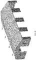
Fig. 1 is a perspective view of the unfolded assembled frame for a one bay structure according to an embodiment of the invention. -
Fig. 2 is a perspective view of the upper folding assembly for the frame inFig. 1 , expanded with frame components unfolded. -
Fig. 3 is a perspective view of the upper folding assembly for the frame as shown inFig. 2 , folded for packing. -
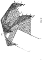
Fig. 4 is a perspective view of the upper folding assembly for the frame as shown inFig. 2 , partially unfolded. -
Fig. 5 is a perspective view of the upper folding assembly for the frame as shown inFig. 2 , further unfolded. -
Fig. 6 is a perspective view of the upper folding assembly for the frame as shown inFig. 2 , further unfolded and standing upright. -
Fig. 7 is a perspective view of the upper folding assembly for the frame as shown inFig. 2 , standing upright further unfolded. -
Fig. 8 is a perspective view of the upper folding assembly for the frame as shown inFig. 2 , standing upright completely unfolded. -
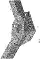
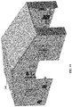
Fig. 9 is a perspective view of a Peak Bracket. -
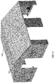
Fig. 10 is a perspective view of the Peak Bracket shown inFig. 9 partially in cross-section, showing chord connections, peak hinge, and sliding lock mechanism with lockout feature. -
Fig. 11 is a perspective view of a detail of the sliding lock mechanism with lockout feature. -
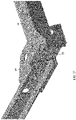
Fig. 12 is a perspective view of the chord knee bracket. -
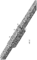
Fig. 13 is a perspective view partially in cross-section of the chord knee bracket ofFig. 12 showing the sliding lock mechanism with lockout feature. -
Fig. 14 is a perspective view of a purlin knee bracket. -
Fig. 15 is a detail front perspective view partially in cross-section of the purlin knee Bracket ofFig. 14 , with sliding lock mechanism but no lockout feature. -
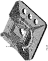
Fig. 16 is a detail rear perspective view of an eave bracket. -
Fig. 17 is a detail perspective view partially in cross-section of the eave bracket ofFig. 16 . -
Fig. 18 is a detail front perspective view of the eave bracket ofFig. 16 with a leg inserted. -
Fig. 19 is a detail front perspective view in partial cross-section of the eave bracket ofFig. 18 with leg inserted, shown resting in place on the upper leg bosses. -
Fig. 20A is a detail front perspective view of a leg assembly. -
Fig. 20B is a detail front perspective view of a top portion of the leg assembly ofFig. 20A showing pinned bosses and a close haul wire hook for cover connection. -
Fig. 21A is a detail front view of a leg knee joint. -
Fig. 21B is a detail front view of the leg knee joint ofFig. 21A partially in cross-section showing a locking slider. -
Fig. 22 and23 are perspective detail views of a quick release foot assembly. -
Fig. 24 is a perspective view of the midspan chord. -
Fig. 25 is a detail perspective view of the midspan chord knee joint. -
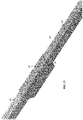
Fig. 26 is a detail perspective view partially in cross-section showing the midspan chord knee joint with lock slider. -
Fig. 27 is a perspective view of the midspan chord partially folded. -
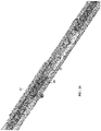
Fig. 28 is a perspective view of the midspan chord fully folded. -
Fig. 29 is a perspective view of a telescoping wind kit post. -
Fig. 30 is a detail perspective view of the wind kit post connection. -
Fig. 31 is an isolated detail perspective view of the connecting bracket of the wind kit post. -
Fig. 32 is an isolated detail perspective view of the connecting fastener on the chord for the wind kit post. -
Fig. 33 is a detail perspective view of the wind kit foot. -
Fig. 34 is a perspective view of the unfolded assembled frame for a two bay structure according to an embodiment of the invention. -
Fig. 35 is a perspective view of the unfolded assembled frame for a four bay structure according to an embodiment of the invention. -
Fig. 36 is a perspective view of a completed cover for a one bay structure. -
Fig. 37 is a detail perspective view of one endwall for the cover shown inFig. 36 . -
Fig. 38 is a detail perspective view of the barrel section for the cover shown inFig. 36 . -
Fig. 39 is a detail perspective view of the second endwall for the cover shown inFig. 36 . -
Fig. 40 is a detail perspective view of the exterior of a soft door assembly for the cover shown inFig. 36 . -
Fig. 41 is detail perspective view of the interior of the soft door assembly for the cover shown inFig. 36 . -
Fig. 42 is a perspective view of a completed cover for a two bay structure. -
Fig. 43 is a perspective view of a completed cover for a four bay structure. -
Fig. 44 is a perspective view of a removable insulation package for a single bay structure. -
Fig. 45 is a perspective view of the endwall for the removable insulation package shown inFig. 44 , both endwalls being the same. -
Fig. 46 is a perspective view of the barrel for the removable insulation package shown inFig. 44 . -
Fig. 47 is a perspective view of the removable insulation package for a two bay structure. -
Fig. 48 is a perspective view of the removable insulation package for a four bay structure. -
Fig. 49 is a perspective view of a solar shade for use with the shelter shown inFig. 36 . -
Fig. 50 is a perspective view of a winter fly for use with the shelter shown inFig. 36 . - Throughout the following description specific details are set forth in order to provide a more thorough understanding to persons skilled in the art. However, well known elements may not have been shown or described in detail to avoid unnecessarily obscuring the disclosure. Accordingly, the description and drawings are to be regarded in an illustrative, rather than a restrictive, sense.
- With reference to
Fig. 1 , an unfoldedframe assembly 10 for a one bay structure according to an embodiment of the invention is shown. Unfoldedframe assemblies Fig. 34 and35 . Eachframe assembly 10 comprises an upper section assembly 12 (Fig. 2 ) which includes fully attachedfolding purlins 14.Frame assembly 10 also comprisespeak brackets 16,eave brackets 17,chords 18,legs 20, wind kit posts 22,midspan chords 24, chord knee joints 26, purlin knee joints 28, and leg knee joints 30. Such joints contain self-resetting lock mechanisms as described below. During set up they lock the joints into place without needing to be touched. Once unlocked they reset to automatically lock the joints into place on the next setup. - Peak bracket and chord joint locks contain a secondary feature which allows joints to be set into an unlocked position until the joint is bent, at which time the lock resets, ready to lock the joint into position on the next setup. This facilitates the pack up procedure, as multiple joint locks need not be manually held unlocked at the same time.
-
Fig. 3 shows theupper folding assembly 12 for the frame as shown inFig. 1 and2 , folded for packing. InFig. 4 one set of two foldedchords 18 and one foldedpurlin 14 are rotated about the hingedpeak bracket 16 to separate from the set of two foldedchords 18 and two foldedpurlin 14. InFig. 5 thechords 18 are unfolded by rotating at chord knee joints 26. InFig. 6 the partially unfolded upper frame assembly is placed in an upright position and as shown inFig. 7 purlins 14 are unfolded about hinged purlin knee joints 28, to reach the unfolded configuration shown inFig. 8 . -
Peak brackets 16 are hingedly connected tochord 18 aboutaxis 30. When in the unfolded position shown inFig. 9 and10 , thechord 18 is locked in place bypins 32 which are mounted on interior sliding lockingframe 34 and extend throughslots 36 in the sides ofchords 18, and intoslots 38.Pins 32 are biased byspring 40 into the locked position shown inFig. 9 . Pulling oncable 42 slides sub-frame 34 away from thepeak bracket 16, releasingpin 32 fromslot 38 and allowingchord 18 to rotate. - Thus peak bracket joints, chord knee joints, purlin knee joints, and leg knee joints all contain self-resetting lock mechanisms. During set up they lock the joints into place without needing to be touched. Once unlocked they reset to automatically lock the joints into place on the next setup.
- As previously noted
peak brackets 16 and chord knee joints 26, contain a secondary lockout feature which allows joints to be set into an unlocked position until the joint is bent, at which time the lock resets, ready to lock the joint into position on the next setup. This assists the pack up procedure, as multiple joint locks didn't need to be manually held unlocked at the same time. Lockout bars 44 permit thechords 18 to be kept in an extended unfolded position without locking. With reference toFig. 11 ,lockout bar 44 is hingedly mounted onpin 32 on slidinglocking frame 34. It is biased to an upward position byspring 48.Head 46 is sized to move upwardly intoslot 50 of chord knee joint 26 orslot 52 ofpeak bracket 16. By pulling oncable 42 the operator can unlock the joint by allowinghead 46 to extend intoslot 50/52 to prevent the joint from re-locking while keeping the joint unfolded. Once the joint is bent,head 46 comes out ofslot 50/52 at which time the lock resets, ready to lock the joint into position on the next setup. - Chord knee bracket shown in
Fig. 12 and13 operates in the same way as thepeak bracket 16 using slidinglocking frame 34. - Purlin knee joints 28, and leg knee joints 30 operate in the same manner as the
chord knee bracket 26 and thepeak bracket 16 without the secondary lockout feature.Purlin knee bracket 28 is shown inFig. 14 .Purlin sections axis 64. When in the unfolded position shown inFig. 14 and15 , thepurlin sections pins 66 which are mounted on interior sliding lockingframe 68 and extend throughslots 70 in the sides of the purlins, and intoslots 72.Pins 66 are biased byspring 67 into the locked position shown inFig. 14 . Pulling oncable 69slides locking frame 68, releasingpins 66 fromslot 72 and allowingpurlin sections -
Eave brackets 17 receive theupper end 21 oflegs 20 throughapertures 23. Thelower surface 25 ofbracket 17 rests onupper leg bosses 27 when the legs are in place. As shown inFig. 19 and20B ,leg 20 may be provided with close haul wire j-hook 29 for cover connection. As noted above, leg knee joints 30 operate in the same manner as thechord knee bracket 26 and thepeak bracket 16 without the secondary lockout feature. Leg knee joint 30 is shown inFig. 21A and 21B .Leg sections axis 35. When in the unfolded position shown inFig. 21A and 21B ,leg sections pins 37 which are mounted on interior sliding lockingframe 39 and extend throughslots 41 in the sides of thelegs 20, and intoslots 43.Pins 37 are biased byspring 45 into the locked position shown inFig. 21A . Pulling onboss 47slides locking frame 39, releasingpins 37 fromslot 43 and allowingleg sections -
Fig. 22 and23 show a quickrelease foot assembly 80 for attachment tolegs 20. Such quick release feet allow a high wind set up and tear down procedure, where thefeet 80 are removed from thelegs 20 before setup, attached to the shelter's floor and securely anchored to the ground throughapertures 84. When the frame is erected, horizontal cylindrical extensions (not shown) on thelegs 20 snap intoslots 86 in thepre-anchored feet 80 to be held in place by spring-biased hingedarms 83, greatly reducing the risk of injury to personnel or damage to equipment. High wind take down is the opposite of set up, where the shelter feet can be released from the leg assembly by using a foot to forceopen arms 83, which allows a steady two-handed grasp on the leg at all times.Foot pads 80 are also sized to allow a low enough ground pressure, even with a snow loaded shelter, such that any ground capable of supporting a walking individual, or a vehicle driving on normal tires, is sufficient to support the shelter. -
Midspan chords 24 are shown inFig. 24 through 28 . Eachchord 24 comprises a single folding element which, when unfolded as shown inFig. 24 , rests onupper frame assembly 12, with itscentral hinge 25 onpeak purlin bracket 28 and its ends onlower purlin brackets 28. The midspan chord knee joints 27 fold and lock/unlock thechord sections cable 29 to unlock the joint. - A telescoping
wind kit post 110 is illustrated inFig. 29 through 33 . Such posts can be attached tochords 18 at either end of theframe 10, in order to assist in securing the cover to the structure, as follows. Eachpost 110 has a telescopingvertical post 112, the interior telescopic section being secured at its lower end to windkit post foot 116. At its upper end thepost 112 is provided with a bracket 113 having akeyhole slot 118 which engages abolt 120 onchord 18. - As shown in
Fig. 34 and35 , the size of the modular structure can be increased by increasing the number ofchords 18,purlins 14 andpeak brackets 16 in theupper frame assembly 12, with proportionate increase in the number oflegs 20 andmidspan chords 24. The resulting structure may thereby accommodate a two or four bays for equipment storage. -
Fig. 36 illustrates a completedfabric cover 220 for the one bay structure whoseframe 10 is shown inFig. 1 . It includes anendwall 222 shown inFig. 37 , abarrel section 224 shown inFig. 38 , and asecond endwall 226 shown inFig. 39 . Asoft door assembly 227 may be used fordoors 228, whose exterior is shown inFig. 40 and interior inFig. 41 . For the two bay structure shown inFig. 42 , twobarrel sections 224 are used and four are used for the four bay structure shown inFig. 43 . -
Insulation 240 can be added to the structure as shown inFig. 44 for a single bay structure. It comprises twoinsulation endwalls 242 for the removable insulation package shown inFig. 45 , both endwalls being the same. Thebarrel 244 for the removable insulation package is shown inFig. 46 . Again for the two bay structure as shown inFig. 47 , twobarrel sections 244 are used and four are used for the four bay structure shown inFig. 48 . -
Fig. 49 illustrates asolar shade 250 for use with the one bay shelter shown inFig. 36 , andFig. 50 illustrates awinter fly 252 for use with the one-bay shelter. Both assemblies are tensioned just at the gable ends with a parabolically curved wire rope which is anchored to the feet on the corner legs. This wire rope acts similarly to the main support cable in a tension bridge, only inverted. This makes fitment and proper tensioning simpler. - The
fabric cover 220 can be attached after the frame has been erected.Fabric cover 220 may be attached to the frame elements using fasteners such as hooks or hook and loop fasteners and in particular close haul j-hooks 29 at the eaves as previously noted above. Fabric dry bag style port closures are preferred. PALS (Pouch Attachment Ladder System)/ Modular Lightweight Load-carrying Equipment i.e. PALS/MOLLE webbing attachment patches as universal hardware mounts may be incorporated. Universal webbing strip/patches may be sewn into the ceiling for attaching accessories such as air distribution ducts, lights, room dividers, etc. Glow in the dark, reversible, fabric exit signs may be used. Double layered windows allow visibility without losing insulating air gap between cover and insulation layer. - While a number of exemplary aspects and embodiments have been discussed above, those of skill in the art will recognize certain modifications, permutations, additions and sub combinations thereof. Therefore the invention is defined by the scope of the appended claims.
Claims (5)
- A folding tent frame component comprising:a) a peak bracket (16) and a chord (18), or a chord knee bracket (26) and a chord (18), pivotally attached for relative rotation about a first axis of rotation located in said peak bracket (16) or chord knee bracket (26), between an open position capable of forming part of an erected tent frame and a closed folded position, said chord (18) comprising a first end proximate said first axis of rotation;b) a sliding locking frame (34) slideably movable in said chord (18), said sliding locking frame (34) comprising a locking pin (32) secured thereto and a lock-out bar (44) pivotally mounted thereon and extending therefrom,c) a first spring (67) arranged to bias said sliding locking frame (34) towards said first end of said chord (18) and a second spring (48) arranged to bias said lock-out bar (44) away from said sliding locking frame (34) to an upward position;wherein said peak bracket (16) or chord knee bracket (26) comprises a pin-receiving slot (38) with a closed end in the direction towards said axis of rotation and open in the opposite direction away from said axis of rotation arranged to reversibly receive said locking pin (32) when said peak bracket (16) or chord knee bracket (26) and said chord (18) are in said open position, and a slot (50, 52) arranged to reversibly receive a head (46) of said lockout bar (44) when said sliding locking frame (34) is moved away from said axis of rotation to withdraw said locking pin (32) from said pin-receiving slot (38); whereby when said locking pin (32) is received in said pin-receiving slot (38) said peak bracket (16) or chord knee bracket (26) and chord (18) are locked in said open position in the absence of other forces on said sliding locking frame (34), and when said sliding locking frame (34) is moved away from said axis of rotation to withdraw said locking pin (32) from said pin-receiving slot (38), said head of said lock-out bar (44) moves into said opening arranged to reversibly receive a portion of said lockout bar (44) to thereby prevent said sliding locking frame (34) from moving back towards said axis of rotation to again lock said peak bracket (16) or chord knee bracket (26) and chord (18) in said open position, and when said portion of said lock-out bar (44) is received in said slot (50, 52) to reversibly receive a portion of said lockout bar (44) said peak bracket (16) or chord knee bracket (26) and chord (18) can be rotated to said second closed folded position;and whereby when said peak bracket (16) or chord knee bracket (26) and chord (26) are rotated back to said open position said locking pin (32) is moved back into said pin-receiving slot (38) by said first spring (67) to thereby again lock said peak bracket (16) or chord knee bracket (26) and chord (18) in said open position.
- The folding tent frame component of claim 1 further comprising means attached to said sliding locking frame (34) to allow an individual to pull said sliding locking frame (34)away from said axis of rotation.
- The folding tent frame component of claim 1 wherein said lock-out bar (44) is pivotally secured at one end thereof to said sliding locking frame (34) and is sized and shaped at the opposite end to extend into said opening for reversibly receiving a portion of said lockout bar (44) when said sliding locking frame (34) is moved away from said axis of rotation to withdraw said locking pin (32) from said pin-receiving slot (38).
- A folding tent frame comprising a plurality of frame elements comprising the folding tent frame component of claim 1.
- A method of assembling and disassembling a tent frame using a plurality of folding frame elements, each frame element comprising the folding tent frame component of claim 1, by i) locking said peak bracket (16) or chord knee bracket (26) and chord (18) of one or more of said tent frame components in the open position to assemble said tent frame by rotating said peak bracket (16) or chord knee bracket (26) and chord (18) to said open position whereby said locking pin (32) is moved into said pin-receiving slot (38) by said first spring (67) to lock said peak bracket (16) or chord knee (26) and chord (18) in said open position; ii) to disassemble said tent frame, unlocking said peak bracket (16) or chord knee bracket (26) and chord (18) of said one or more tent frame components while maintaining said peak bracket (16) or chord knee bracket (26) and chord (18) in the open position by moving said sliding locking frame (34) away from said axis of rotation to withdraw said locking pin (32) from said pin-receiving slot (38), and said head (46) of said lock-out bar (44) moving into said slot (50, 52) for reversibly receiving a portion of said lockout bar (44) to thereby prevent said sliding locking frame (34) from moving back towards said axis of rotation to again lock said peak bracket (16) or chord knee bracket (26) and chord (18) in said open position while disassembling said tent frame; and iii) subsequently rotating said peak bracket (16) or chord knee bracket (26) and chord (18) to said second closed folded position.
Applications Claiming Priority (2)
| Application Number | Priority Date | Filing Date | Title |
|---|---|---|---|
| US201662287313P | 2016-01-26 | 2016-01-26 | |
| PCT/CA2017/050071 WO2017127920A1 (en) | 2016-01-26 | 2017-01-25 | Rapidly deployable modular shelter system |
Publications (3)
| Publication Number | Publication Date |
|---|---|
| EP3408472A1 EP3408472A1 (en) | 2018-12-05 |
| EP3408472A4 EP3408472A4 (en) | 2019-10-09 |
| EP3408472B1 true EP3408472B1 (en) | 2022-11-16 |
Family
ID=59396819
Family Applications (1)
| Application Number | Title | Priority Date | Filing Date |
|---|---|---|---|
| EP17743515.3A Active EP3408472B1 (en) | 2016-01-26 | 2017-01-25 | Foldable structure |
Country Status (11)
| Country | Link |
|---|---|
| US (1) | US10392828B2 (en) |
| EP (1) | EP3408472B1 (en) |
| AU (1) | AU2017212161B2 (en) |
| CA (1) | CA3012262C (en) |
| ES (1) | ES2932178T3 (en) |
| HU (1) | HUE060713T2 (en) |
| LT (1) | LT3408472T (en) |
| PL (1) | PL3408472T3 (en) |
| PT (1) | PT3408472T (en) |
| WO (1) | WO2017127920A1 (en) |
| ZA (1) | ZA201805619B (en) |
Families Citing this family (7)
| Publication number | Priority date | Publication date | Assignee | Title |
|---|---|---|---|---|
| US10620506B2 (en) * | 2017-09-29 | 2020-04-14 | Christina Wehbe | Portable device for controlling photography lighting |
| FR3072702A1 (en) * | 2017-10-25 | 2019-04-26 | Jean Samuel Gotlibowicz | AUTOMATIC CHAPTEAU |
| USD909280S1 (en) * | 2018-08-01 | 2021-02-02 | 9206-0979 Quebec Inc. | Rollable and motorized door for vehicle shelter |
| USD909281S1 (en) * | 2018-10-31 | 2021-02-02 | Load Lugger, Llc | ATV and/or UTV garage bag |
| JP7344306B2 (en) * | 2019-02-27 | 2023-09-13 | ウェザーヘイブン グローバル リソーシズ リミテッド | Leg elements, folding tent frame, shelter system and method of deploying the shelter |
| SK9201Y1 (en) * | 2020-09-16 | 2021-06-23 | Zepelin S R O | Folding tent frame |
| USD1013211S1 (en) * | 2023-07-11 | 2024-01-30 | Yu Wang | Canopy |
Citations (2)
| Publication number | Priority date | Publication date | Assignee | Title |
|---|---|---|---|---|
| US1291947A (en) * | 1917-03-28 | 1919-01-21 | John Levis Linville | Tent and portable and knockdown house. |
| US6089247A (en) * | 1998-08-12 | 2000-07-18 | Price; Walter L. | Collapsible frame |
Family Cites Families (33)
| Publication number | Priority date | Publication date | Assignee | Title |
|---|---|---|---|---|
| US1170188A (en) | 1915-04-26 | 1916-02-01 | Gold Medal Camp Furniture Mfg Co | Folding frame for portable buildings. |
| GB680294A (en) | 1949-11-17 | 1952-10-01 | James Hardress De Warrenne Wal | Improvements in and relating to reinforced concrete arched structures |
| US2771896A (en) | 1951-04-19 | 1956-11-27 | Telatent Company Inc | Collapsible tent framework |
| US2828756A (en) | 1955-10-21 | 1958-04-01 | Harold Smith J | Sectional tent |
| GB982411A (en) | 1961-12-27 | 1965-02-03 | Karl Heinz Klahold | Collapsible tent frame |
| CA852526A (en) | 1968-03-14 | 1970-09-29 | Mollinger Sebastian | Connection of sheets to cables or rods |
| US4066089A (en) | 1976-05-17 | 1978-01-03 | Rainwater Orman M | Collapsible shelter structure |
| JPS5539513A (en) | 1978-09-10 | 1980-03-19 | Yoshihiro Yonahara | Simply assembled structure |
| US4365908A (en) | 1980-12-17 | 1982-12-28 | Les Entreprises Rotot Ltee | Folding joint for interconnecting elongate members |
| US4667692A (en) | 1982-08-23 | 1987-05-26 | Brunswick Corporation | Expandable soft side shelter |
| IL78714A0 (en) | 1986-05-07 | 1986-08-31 | Israel State | Self-locking assembly |
| CA1287725C (en) | 1987-05-28 | 1991-08-20 | Bureau International D'echange Commercial (Biec) Ltee | Inflatable wall structure |
| US5159790A (en) | 1989-04-07 | 1992-11-03 | Harding Lewis R | Frame structure |
| US5167246A (en) | 1990-05-21 | 1992-12-01 | Magline, Inc. | Rapidly erectable and strikeable shelter frame system and methods of erecting and striking such systems |
| EP0494053A1 (en) | 1990-12-31 | 1992-07-08 | EUROVINIL INDUSTRIES S.p.A. | Construction in the form of a shed or hangar with a pneumatic supporting structure |
| GB9107570D0 (en) | 1991-04-10 | 1991-06-05 | Dowty Hoybond Limited | Arched structure |
| FR2681626B1 (en) | 1991-09-25 | 1998-04-03 | Raclet | FRAME FOR RECTANGULAR TENT HAVING TWO-PANEL ROOF. |
| US5263507A (en) | 1992-12-16 | 1993-11-23 | Chuang Ching Pao | Collapsible tent frame |
| JP2819014B2 (en) | 1995-11-29 | 1998-10-30 | 孝明 椎名 | Frame of a simple building |
| US5884647A (en) | 1997-08-15 | 1999-03-23 | Dwek; Abraham | Folding structure |
| US6550491B1 (en) | 1999-12-14 | 2003-04-22 | World Patent Development Corporation | Portable structure |
| ATE318975T1 (en) | 2003-07-01 | 2006-03-15 | Utilis S A | QUICK ASSEMBLE, MODULAR AND FOLDABLE STRUCTURE FOR TENTS OR THE LIKE |
| US7357140B2 (en) | 2004-03-30 | 2008-04-15 | Best Tide Manufacturing Co., Ltd. | Collapsible structure |
| US8033289B2 (en) | 2005-04-01 | 2011-10-11 | Buckley Scott L | Adjustable tarpaulin support |
| ZA200800570B (en) | 2007-03-30 | 2008-12-31 | Shelter Trust | Collapsible tent or marquee |
| US7975712B2 (en) | 2007-12-28 | 2011-07-12 | Beacco Michael A | Hunting blind |
| CN201169955Y (en) | 2008-01-22 | 2008-12-24 | 李成熙 | Connecting pieces of automatic foldable tent rack |
| US8186369B2 (en) | 2008-05-14 | 2012-05-29 | Swimways Corporation | Collapsible shelter |
| CN201225023Y (en) * | 2008-07-09 | 2009-04-22 | 秋野地(厦门)露营用品有限公司 | Rapidly-folding structure of tent frame rod |
| CN101463671B (en) | 2008-09-09 | 2011-03-23 | 中国人民解放军总后勤部建筑工程研究所 | Universal overall folding frame tent frame |
| GB2475512B (en) | 2009-11-20 | 2014-02-26 | Nbc Service Ltd | Tents and support frames for tents |
| ITMI20100809A1 (en) | 2010-05-06 | 2011-11-07 | Covering Di Baldussi Carlo | FOLDABLE TUNNEL COVERING CURTAIN. |
| FR3013374B1 (en) * | 2013-11-21 | 2015-12-11 | Becher Stp | FOLDABLE MODULAR STRUCTURE FOR TENT OR SIMILAR HOUSING WITH QUICK MOUNTING |
-
2017
- 2017-01-25 US US16/072,124 patent/US10392828B2/en active Active
- 2017-01-25 PT PT177435153T patent/PT3408472T/en unknown
- 2017-01-25 LT LTEPPCT/CA2017/050071T patent/LT3408472T/en unknown
- 2017-01-25 EP EP17743515.3A patent/EP3408472B1/en active Active
- 2017-01-25 WO PCT/CA2017/050071 patent/WO2017127920A1/en not_active Ceased
- 2017-01-25 CA CA3012262A patent/CA3012262C/en active Active
- 2017-01-25 HU HUE17743515A patent/HUE060713T2/en unknown
- 2017-01-25 PL PL17743515.3T patent/PL3408472T3/en unknown
- 2017-01-25 ES ES17743515T patent/ES2932178T3/en active Active
- 2017-01-25 AU AU2017212161A patent/AU2017212161B2/en active Active
-
2018
- 2018-08-22 ZA ZA2018/05619A patent/ZA201805619B/en unknown
Patent Citations (2)
| Publication number | Priority date | Publication date | Assignee | Title |
|---|---|---|---|---|
| US1291947A (en) * | 1917-03-28 | 1919-01-21 | John Levis Linville | Tent and portable and knockdown house. |
| US6089247A (en) * | 1998-08-12 | 2000-07-18 | Price; Walter L. | Collapsible frame |
Also Published As
| Publication number | Publication date |
|---|---|
| HUE060713T2 (en) | 2023-04-28 |
| AU2017212161A1 (en) | 2018-08-16 |
| PT3408472T (en) | 2022-12-07 |
| PL3408472T3 (en) | 2023-03-13 |
| US20190032361A1 (en) | 2019-01-31 |
| ZA201805619B (en) | 2019-05-29 |
| US10392828B2 (en) | 2019-08-27 |
| AU2017212161B2 (en) | 2021-09-09 |
| WO2017127920A1 (en) | 2017-08-03 |
| LT3408472T (en) | 2023-01-25 |
| ES2932178T3 (en) | 2023-01-16 |
| CA3012262C (en) | 2023-10-03 |
| EP3408472A1 (en) | 2018-12-05 |
| EP3408472A4 (en) | 2019-10-09 |
| CA3012262A1 (en) | 2017-08-03 |
Similar Documents
| Publication | Publication Date | Title |
|---|---|---|
| CA3012262C (en) | Rapidly deployable modular shelter system | |
| US11377868B2 (en) | Rapidly deployable modular shelter system | |
| US4667692A (en) | Expandable soft side shelter | |
| EP3794188B1 (en) | Arthritic-assisting one-person-deploying popup | |
| CA2816689C (en) | Foldable tent | |
| US5671766A (en) | Portable, adjustable tent assembly | |
| US20240309672A1 (en) | Multifunctional gazebo | |
| US20230287702A1 (en) | Portable shelters | |
| US11746555B2 (en) | Rapidly deployable modular shelter system | |
| WO2015009738A1 (en) | Adjustable free standing shelter | |
| AU2022211914B2 (en) | Rapidly deployable modular shelter system | |
| RU2074939C1 (en) | Collapsible canopy-type shelter | |
| CA3228416A1 (en) | Rapidly deployable modular shelter system |
Legal Events
| Date | Code | Title | Description |
|---|---|---|---|
| STAA | Information on the status of an ep patent application or granted ep patent |
Free format text: STATUS: THE INTERNATIONAL PUBLICATION HAS BEEN MADE |
|
| PUAI | Public reference made under article 153(3) epc to a published international application that has entered the european phase |
Free format text: ORIGINAL CODE: 0009012 |
|
| STAA | Information on the status of an ep patent application or granted ep patent |
Free format text: STATUS: REQUEST FOR EXAMINATION WAS MADE |
|
| 17P | Request for examination filed |
Effective date: 20180820 |
|
| AK | Designated contracting states |
Kind code of ref document: A1 Designated state(s): AL AT BE BG CH CY CZ DE DK EE ES FI FR GB GR HR HU IE IS IT LI LT LU LV MC MK MT NL NO PL PT RO RS SE SI SK SM TR |
|
| AX | Request for extension of the european patent |
Extension state: BA ME |
|
| DAV | Request for validation of the european patent (deleted) | ||
| DAX | Request for extension of the european patent (deleted) | ||
| A4 | Supplementary search report drawn up and despatched |
Effective date: 20190910 |
|
| RIC1 | Information provided on ipc code assigned before grant |
Ipc: E04H 15/44 20060101ALI20190904BHEP Ipc: E04H 15/48 20060101AFI20190904BHEP |
|
| STAA | Information on the status of an ep patent application or granted ep patent |
Free format text: STATUS: EXAMINATION IS IN PROGRESS |
|
| 17Q | First examination report despatched |
Effective date: 20201015 |
|
| GRAP | Despatch of communication of intention to grant a patent |
Free format text: ORIGINAL CODE: EPIDOSNIGR1 |
|
| STAA | Information on the status of an ep patent application or granted ep patent |
Free format text: STATUS: GRANT OF PATENT IS INTENDED |
|
| INTG | Intention to grant announced |
Effective date: 20220105 |
|
| GRAJ | Information related to disapproval of communication of intention to grant by the applicant or resumption of examination proceedings by the epo deleted |
Free format text: ORIGINAL CODE: EPIDOSDIGR1 |
|
| STAA | Information on the status of an ep patent application or granted ep patent |
Free format text: STATUS: EXAMINATION IS IN PROGRESS |
|
| INTC | Intention to grant announced (deleted) | ||
| GRAP | Despatch of communication of intention to grant a patent |
Free format text: ORIGINAL CODE: EPIDOSNIGR1 |
|
| STAA | Information on the status of an ep patent application or granted ep patent |
Free format text: STATUS: GRANT OF PATENT IS INTENDED |
|
| INTG | Intention to grant announced |
Effective date: 20220617 |
|
| GRAS | Grant fee paid |
Free format text: ORIGINAL CODE: EPIDOSNIGR3 |
|
| GRAA | (expected) grant |
Free format text: ORIGINAL CODE: 0009210 |
|
| STAA | Information on the status of an ep patent application or granted ep patent |
Free format text: STATUS: THE PATENT HAS BEEN GRANTED |
|
| AK | Designated contracting states |
Kind code of ref document: B1 Designated state(s): AL AT BE BG CH CY CZ DE DK EE ES FI FR GB GR HR HU IE IS IT LI LT LU LV MC MK MT NL NO PL PT RO RS SE SI SK SM TR |
|
| REG | Reference to a national code |
Ref country code: GB Ref legal event code: FG4D |
|
| REG | Reference to a national code |
Ref country code: CH Ref legal event code: EP |
|
| REG | Reference to a national code |
Ref country code: DE Ref legal event code: R096 Ref document number: 602017063737 Country of ref document: DE |
|
| REG | Reference to a national code |
Ref country code: PT Ref legal event code: SC4A Ref document number: 3408472 Country of ref document: PT Date of ref document: 20221207 Kind code of ref document: T Free format text: AVAILABILITY OF NATIONAL TRANSLATION Effective date: 20221130 Ref country code: IE Ref legal event code: FG4D |
|
| REG | Reference to a national code |
Ref country code: RO Ref legal event code: EPE |
|
| REG | Reference to a national code |
Ref country code: AT Ref legal event code: REF Ref document number: 1531856 Country of ref document: AT Kind code of ref document: T Effective date: 20221215 |
|
| REG | Reference to a national code |
Ref country code: NL Ref legal event code: FP |
|
| REG | Reference to a national code |
Ref country code: SE Ref legal event code: TRGR |
|
| REG | Reference to a national code |
Ref country code: NO Ref legal event code: T2 Effective date: 20221116 |
|
| REG | Reference to a national code |
Ref country code: ES Ref legal event code: FG2A Ref document number: 2932178 Country of ref document: ES Kind code of ref document: T3 Effective date: 20230116 |
|
| REG | Reference to a national code |
Ref country code: EE Ref legal event code: FG4A Ref document number: E022982 Country of ref document: EE Effective date: 20221213 |
|
| REG | Reference to a national code |
Ref country code: AT Ref legal event code: MK05 Ref document number: 1531856 Country of ref document: AT Kind code of ref document: T Effective date: 20221116 |
|
| PG25 | Lapsed in a contracting state [announced via postgrant information from national office to epo] |
Ref country code: FI Free format text: LAPSE BECAUSE OF FAILURE TO SUBMIT A TRANSLATION OF THE DESCRIPTION OR TO PAY THE FEE WITHIN THE PRESCRIBED TIME-LIMIT Effective date: 20221116 Ref country code: AT Free format text: LAPSE BECAUSE OF FAILURE TO SUBMIT A TRANSLATION OF THE DESCRIPTION OR TO PAY THE FEE WITHIN THE PRESCRIBED TIME-LIMIT Effective date: 20221116 |
|
| REG | Reference to a national code |
Ref country code: HU Ref legal event code: AG4A Ref document number: E060713 Country of ref document: HU |
|
| PG25 | Lapsed in a contracting state [announced via postgrant information from national office to epo] |
Ref country code: RS Free format text: LAPSE BECAUSE OF FAILURE TO SUBMIT A TRANSLATION OF THE DESCRIPTION OR TO PAY THE FEE WITHIN THE PRESCRIBED TIME-LIMIT Effective date: 20221116 Ref country code: IS Free format text: LAPSE BECAUSE OF FAILURE TO SUBMIT A TRANSLATION OF THE DESCRIPTION OR TO PAY THE FEE WITHIN THE PRESCRIBED TIME-LIMIT Effective date: 20230316 Ref country code: HR Free format text: LAPSE BECAUSE OF FAILURE TO SUBMIT A TRANSLATION OF THE DESCRIPTION OR TO PAY THE FEE WITHIN THE PRESCRIBED TIME-LIMIT Effective date: 20221116 Ref country code: GR Free format text: LAPSE BECAUSE OF FAILURE TO SUBMIT A TRANSLATION OF THE DESCRIPTION OR TO PAY THE FEE WITHIN THE PRESCRIBED TIME-LIMIT Effective date: 20230217 |
|
| PG25 | Lapsed in a contracting state [announced via postgrant information from national office to epo] |
Ref country code: SM Free format text: LAPSE BECAUSE OF FAILURE TO SUBMIT A TRANSLATION OF THE DESCRIPTION OR TO PAY THE FEE WITHIN THE PRESCRIBED TIME-LIMIT Effective date: 20221116 Ref country code: DK Free format text: LAPSE BECAUSE OF FAILURE TO SUBMIT A TRANSLATION OF THE DESCRIPTION OR TO PAY THE FEE WITHIN THE PRESCRIBED TIME-LIMIT Effective date: 20221116 |
|
| REG | Reference to a national code |
Ref country code: DE Ref legal event code: R097 Ref document number: 602017063737 Country of ref document: DE |
|
| PG25 | Lapsed in a contracting state [announced via postgrant information from national office to epo] |
Ref country code: SK Free format text: LAPSE BECAUSE OF FAILURE TO SUBMIT A TRANSLATION OF THE DESCRIPTION OR TO PAY THE FEE WITHIN THE PRESCRIBED TIME-LIMIT Effective date: 20221116 Ref country code: AL Free format text: LAPSE BECAUSE OF FAILURE TO SUBMIT A TRANSLATION OF THE DESCRIPTION OR TO PAY THE FEE WITHIN THE PRESCRIBED TIME-LIMIT Effective date: 20221116 |
|
| PLBE | No opposition filed within time limit |
Free format text: ORIGINAL CODE: 0009261 |
|
| STAA | Information on the status of an ep patent application or granted ep patent |
Free format text: STATUS: NO OPPOSITION FILED WITHIN TIME LIMIT |
|
| PG25 | Lapsed in a contracting state [announced via postgrant information from national office to epo] |
Ref country code: LU Free format text: LAPSE BECAUSE OF NON-PAYMENT OF DUE FEES Effective date: 20230125 |
|
| 26N | No opposition filed |
Effective date: 20230817 |
|
| PG25 | Lapsed in a contracting state [announced via postgrant information from national office to epo] |
Ref country code: SI Free format text: LAPSE BECAUSE OF FAILURE TO SUBMIT A TRANSLATION OF THE DESCRIPTION OR TO PAY THE FEE WITHIN THE PRESCRIBED TIME-LIMIT Effective date: 20221116 |
|
| PG25 | Lapsed in a contracting state [announced via postgrant information from national office to epo] |
Ref country code: IE Free format text: LAPSE BECAUSE OF NON-PAYMENT OF DUE FEES Effective date: 20230125 |
|
| PGFP | Annual fee paid to national office [announced via postgrant information from national office to epo] |
Ref country code: HU Payment date: 20240111 Year of fee payment: 8 Ref country code: CZ Payment date: 20240109 Year of fee payment: 8 Ref country code: BG Payment date: 20240129 Year of fee payment: 8 Ref country code: PT Payment date: 20240111 Year of fee payment: 8 |
|
| PG25 | Lapsed in a contracting state [announced via postgrant information from national office to epo] |
Ref country code: MC Free format text: LAPSE BECAUSE OF FAILURE TO SUBMIT A TRANSLATION OF THE DESCRIPTION OR TO PAY THE FEE WITHIN THE PRESCRIBED TIME-LIMIT Effective date: 20221116 |
|
| PG25 | Lapsed in a contracting state [announced via postgrant information from national office to epo] |
Ref country code: MC Free format text: LAPSE BECAUSE OF FAILURE TO SUBMIT A TRANSLATION OF THE DESCRIPTION OR TO PAY THE FEE WITHIN THE PRESCRIBED TIME-LIMIT Effective date: 20221116 |
|
| PGFP | Annual fee paid to national office [announced via postgrant information from national office to epo] |
Ref country code: ES Payment date: 20250203 Year of fee payment: 9 |
|
| PGFP | Annual fee paid to national office [announced via postgrant information from national office to epo] |
Ref country code: TR Payment date: 20250205 Year of fee payment: 9 |
|
| PG25 | Lapsed in a contracting state [announced via postgrant information from national office to epo] |
Ref country code: CY Free format text: LAPSE BECAUSE OF FAILURE TO SUBMIT A TRANSLATION OF THE DESCRIPTION OR TO PAY THE FEE WITHIN THE PRESCRIBED TIME-LIMIT; INVALID AB INITIO Effective date: 20170125 |
|
| PG25 | Lapsed in a contracting state [announced via postgrant information from national office to epo] |
Ref country code: HU Free format text: LAPSE BECAUSE OF NON-PAYMENT OF DUE FEES Effective date: 20250126 |
|
| PG25 | Lapsed in a contracting state [announced via postgrant information from national office to epo] |
Ref country code: PT Free format text: LAPSE BECAUSE OF NON-PAYMENT OF DUE FEES Effective date: 20250725 |
|
| PG25 | Lapsed in a contracting state [announced via postgrant information from national office to epo] |
Ref country code: BG Free format text: LAPSE BECAUSE OF NON-PAYMENT OF DUE FEES Effective date: 20250125 |
|
| PG25 | Lapsed in a contracting state [announced via postgrant information from national office to epo] |
Ref country code: CZ Free format text: LAPSE BECAUSE OF NON-PAYMENT OF DUE FEES Effective date: 20250125 |
|
| REG | Reference to a national code |
Ref country code: CH Ref legal event code: U11 Free format text: ST27 STATUS EVENT CODE: U-0-0-U10-U11 (AS PROVIDED BY THE NATIONAL OFFICE) Effective date: 20260201 |
|
| PGFP | Annual fee paid to national office [announced via postgrant information from national office to epo] |
Ref country code: NL Payment date: 20260126 Year of fee payment: 10 |
|
| PGFP | Annual fee paid to national office [announced via postgrant information from national office to epo] |
Ref country code: SE Payment date: 20260127 Year of fee payment: 10 |
|
| PGFP | Annual fee paid to national office [announced via postgrant information from national office to epo] |
Ref country code: GB Payment date: 20260127 Year of fee payment: 10 Ref country code: LT Payment date: 20260202 Year of fee payment: 10 |
|
| PGFP | Annual fee paid to national office [announced via postgrant information from national office to epo] |
Ref country code: NO Payment date: 20260128 Year of fee payment: 10 Ref country code: DE Payment date: 20260128 Year of fee payment: 10 |
|
| PGFP | Annual fee paid to national office [announced via postgrant information from national office to epo] |
Ref country code: BE Payment date: 20260127 Year of fee payment: 10 Ref country code: RO Payment date: 20260205 Year of fee payment: 10 Ref country code: IT Payment date: 20260219 Year of fee payment: 10 |
|
| PGFP | Annual fee paid to national office [announced via postgrant information from national office to epo] |
Ref country code: FR Payment date: 20260126 Year of fee payment: 10 |
|
| PGFP | Annual fee paid to national office [announced via postgrant information from national office to epo] |
Ref country code: CH Payment date: 20260201 Year of fee payment: 10 |
|
| PGFP | Annual fee paid to national office [announced via postgrant information from national office to epo] |
Ref country code: PL Payment date: 20260203 Year of fee payment: 10 |
|
| PGFP | Annual fee paid to national office [announced via postgrant information from national office to epo] |
Ref country code: EE Payment date: 20260210 Year of fee payment: 10 Ref country code: LV Payment date: 20260131 Year of fee payment: 10 |