EP3408467B1 - Bead limb and plaster edge bead - Google Patents
Bead limb and plaster edge bead Download PDFInfo
- Publication number
- EP3408467B1 EP3408467B1 EP17791072.6A EP17791072A EP3408467B1 EP 3408467 B1 EP3408467 B1 EP 3408467B1 EP 17791072 A EP17791072 A EP 17791072A EP 3408467 B1 EP3408467 B1 EP 3408467B1
- Authority
- EP
- European Patent Office
- Prior art keywords
- section
- edge
- limb
- profile
- hinge
- Prior art date
- Legal status (The legal status is an assumption and is not a legal conclusion. Google has not performed a legal analysis and makes no representation as to the accuracy of the status listed.)
- Active
Links
- 239000011505 plaster Substances 0.000 title claims description 117
- 239000011324 bead Substances 0.000 title 2
- 229920003023 plastic Polymers 0.000 claims description 14
- 239000004033 plastic Substances 0.000 claims description 14
- 239000002184 metal Substances 0.000 claims description 12
- 125000006850 spacer group Chemical group 0.000 claims description 6
- 210000002414 leg Anatomy 0.000 description 243
- 238000004519 manufacturing process Methods 0.000 description 14
- 239000004800 polyvinyl chloride Substances 0.000 description 10
- 239000000463 material Substances 0.000 description 8
- 230000013011 mating Effects 0.000 description 8
- 229920000915 polyvinyl chloride Polymers 0.000 description 8
- 239000004952 Polyamide Substances 0.000 description 4
- 239000004698 Polyethylene Substances 0.000 description 4
- 239000004743 Polypropylene Substances 0.000 description 4
- 230000008878 coupling Effects 0.000 description 4
- 238000010168 coupling process Methods 0.000 description 4
- 238000005859 coupling reaction Methods 0.000 description 4
- 238000013461 design Methods 0.000 description 4
- 238000001746 injection moulding Methods 0.000 description 4
- 229920002647 polyamide Polymers 0.000 description 4
- -1 polyethylene Polymers 0.000 description 4
- 229920000573 polyethylene Polymers 0.000 description 4
- 229920001155 polypropylene Polymers 0.000 description 4
- 238000005520 cutting process Methods 0.000 description 3
- 238000000034 method Methods 0.000 description 3
- 238000003860 storage Methods 0.000 description 3
- 210000000689 upper leg Anatomy 0.000 description 3
- 238000005452 bending Methods 0.000 description 2
- 238000010276 construction Methods 0.000 description 2
- 230000000694 effects Effects 0.000 description 2
- 238000001125 extrusion Methods 0.000 description 2
- 239000004814 polyurethane Substances 0.000 description 2
- 238000012545 processing Methods 0.000 description 2
- 230000009467 reduction Effects 0.000 description 2
- 230000006641 stabilisation Effects 0.000 description 2
- 238000011105 stabilization Methods 0.000 description 2
- 229910001335 Galvanized steel Inorganic materials 0.000 description 1
- 229910000831 Steel Inorganic materials 0.000 description 1
- 230000004308 accommodation Effects 0.000 description 1
- 230000009471 action Effects 0.000 description 1
- 230000008901 benefit Effects 0.000 description 1
- 230000008859 change Effects 0.000 description 1
- 239000003795 chemical substances by application Substances 0.000 description 1
- 238000005260 corrosion Methods 0.000 description 1
- 230000007797 corrosion Effects 0.000 description 1
- 230000001419 dependent effect Effects 0.000 description 1
- 238000011161 development Methods 0.000 description 1
- 230000018109 developmental process Effects 0.000 description 1
- 239000000834 fixative Substances 0.000 description 1
- 239000008397 galvanized steel Substances 0.000 description 1
- 238000003780 insertion Methods 0.000 description 1
- 230000037431 insertion Effects 0.000 description 1
- 238000002372 labelling Methods 0.000 description 1
- 239000004570 mortar (masonry) Substances 0.000 description 1
- 230000035515 penetration Effects 0.000 description 1
- 238000003825 pressing Methods 0.000 description 1
- 230000008569 process Effects 0.000 description 1
- 230000000717 retained effect Effects 0.000 description 1
- 238000007493 shaping process Methods 0.000 description 1
- 239000010959 steel Substances 0.000 description 1
Images


Classifications
-
- E—FIXED CONSTRUCTIONS
- E04—BUILDING
- E04F—FINISHING WORK ON BUILDINGS, e.g. STAIRS, FLOORS
- E04F13/00—Coverings or linings, e.g. for walls or ceilings
- E04F13/02—Coverings or linings, e.g. for walls or ceilings of plastic materials hardening after applying, e.g. plaster
- E04F13/04—Bases for plaster
- E04F13/06—Edge-protecting borders
-
- E—FIXED CONSTRUCTIONS
- E04—BUILDING
- E04F—FINISHING WORK ON BUILDINGS, e.g. STAIRS, FLOORS
- E04F13/00—Coverings or linings, e.g. for walls or ceilings
- E04F13/02—Coverings or linings, e.g. for walls or ceilings of plastic materials hardening after applying, e.g. plaster
- E04F13/04—Bases for plaster
- E04F13/045—Means for fastening plaster-bases to a supporting structure
-
- E—FIXED CONSTRUCTIONS
- E04—BUILDING
- E04F—FINISHING WORK ON BUILDINGS, e.g. STAIRS, FLOORS
- E04F21/00—Implements for finishing work on buildings
- E04F21/0053—Implements for finishing work on buildings for installing edge-protecting borders
-
- E—FIXED CONSTRUCTIONS
- E04—BUILDING
- E04F—FINISHING WORK ON BUILDINGS, e.g. STAIRS, FLOORS
- E04F13/00—Coverings or linings, e.g. for walls or ceilings
- E04F13/02—Coverings or linings, e.g. for walls or ceilings of plastic materials hardening after applying, e.g. plaster
- E04F13/04—Bases for plaster
- E04F13/06—Edge-protecting borders
- E04F2013/063—Edge-protecting borders for corners
Definitions
- Another aspect of the invention relates to the use of a profile leg according to the invention for producing an edge plaster profile.
- the profile leg is divided between the corner longitudinal edge and the distal longitudinal edge and the hinge axis is inserted into the hinge socket in order to produce the edge trim profile.
- the fixing means is preferably in the form of a bar-shaped spacer, in particular, the spacer having at least one holding section which can be coupled to a mating section formed on one of the profile legs for fixing the set angle.
- the mating section is particularly preferably designed as a fixing opening formed in the profile leg.
- Such a counter-section designed as a fixing opening can be produced particularly easily, for example by injection molding, without an additional work step being necessary for this. Alternatively, such a fixing opening can be punched out of the leg surfaces at any point as required.
- the fixing means is fixed at one end but can be pivoted, in particular with a film hinge, attached to one of the profile legs. This makes it possible to produce the fixing means together with the profile leg, for example by an injection molding process.
- the fixing means has at least two opposing holding sections.
- an adjustment gauge can be used which comprises a flat base body with an adjustment side, with at least one fixation receptacle and at least one adjustment receptacle being provided on the adjustment side, the fixation receptacle for receiving a first profile leg and the adjustment receptacle are designed to receive a second profile leg of the edge plastering profile, wherein the at least one fixing receptacle has an undercut acting in the direction of the adjustment side for the first profile leg of the edge plastering profile, which counteracts removal of a first profile leg received in the fixing receptacle in the direction of the adjustment side, and at least an adjustment receptacle is designed so that the second profile leg of the edge trim profile can be inserted into it.
- the undercut of the fixation receptacle is formed by a projection extending away from the at least one adjustment receptacle, which projection is designed such that the first profile leg of the edge trim profile can be hooked onto it.
- a handle side can be provided opposite the adjustment side, the adjustment side and the handle side spanning a gripping surface.
- the flat base body of the adjustment gauge preferably has a thickness which extends perpendicular to the grip surface and which is smaller than a length of the grip side.
- the thickness is particularly preferably less than or equal to 5.0 cm, most preferably less than or equal to 3.0 cm.
- the thickness between 0.3 cm and 1 cm, in particular approx. 0.5 cm, is particularly preferred.
- An adjustment gauge with such a thickness can be gripped particularly well and still has the necessary stability to be guided over the length of the edge plaster profile and thereby set the desired angle between the two profile legs of the edge plaster profile.
- the first profile leg 2 preferably has, in addition to the hinge axis 10 provided on the connecting section 6, a hinge bush 11 which runs along the distal longitudinal edge 5.
- the second profile leg 8 can have a hinge axis 10 along its distal longitudinal edge 5, in addition to the hinge bushing 11 running along its corner longitudinal edge 4. In this case, in a folded state of the edge trim profile 1, as in FIG Fig.
- corresponding counter-locking means can also be provided on the outside of the hinge axis 10.
- the securing means 25 as well as the counter-locking means can for example be designed as transverse grooves or projections or as corrugations or the like.
Description
Die vorliegende Erfindung betrifft einen Profilschenkel, ein Kantenputzprofil mit einem ersten solchen Profilschenkel und einem zweiten Profilschenkel sowie die Verwendung eines solchen Kantenputzprofils.The present invention relates to a profile leg, an edge plaster profile with a first such profile leg and a second profile leg and the use of such an edge plaster profile.
Ein Profilschenkel mit den Merkmalen des Oberbegriffs des Anspruchs 1 ist aus der
In Eckbereichen von Wänden werden Kantenputzprofile eingesetzt, um einerseits eine für das Verputzen notwendige Abzugskante bereitzustellen und andererseits im Kantenbereich eine Stabilisierung zu bewirken, sodass die Kante nicht bereits bei leichter Beanspruchung bricht. Durch den Einsatz unterschiedlicher Kantenputzprofile, die sich bezüglich ihres durch die Profilschenkel gebildeten Winkels unterscheiden, lassen sich verschiedene Putzstärken realisieren oder Kanten mit unterschiedlichen Winkeln verputzen.Edge plaster profiles are used in corner areas of walls, on the one hand to provide a pull-off edge necessary for plastering and, on the other hand, to provide stabilization in the edge area so that the edge does not break even when it is lightly used. By using different edge plaster profiles, which differ in terms of the angle formed by the profile legs, different plaster thicknesses can be implemented or edges can be plastered with different angles.
Gängige Kantenputzprofile werden oftmals aus Metall hergestellt. Mit solchen aus Metall hergestellten Kantenputzprofilen lassen sich zwar gut stabilisierte Eckbereiche realisieren, jedoch ist deren Produktion verhältnismäßig aufwendig und teuer. Der Herstellungsaufwand steigt weiter an, wenn diese Kantenputzprofile aus Metall zusätzlich verzinkt werden müssen, um eine entsprechende Korrosionsbeständigkeit zu erzielen. Zudem ist bei derartigen Kantenputzprofilen der durch die Profilschenkel gebildete Winkel nicht veränderbar. Als Konsequenz muss für unterschiedliche Putzstärken jeweils ein anderes Kantenputzprofil vorgehalten und verwendet werden. Zwar wäre es denkbar, den durch die Profilschenkel gebildete Winkel durch ein Verbiegen des Kantenputzprofils beispielsweise auf der Baustelle zu verändern, jedoch ist es in der Praxis nicht möglich, über die gesamte Länge des Kantenputzprofils einen gleichmäßigen Winkel einzustellen, so dass ein derartiges verbogenes Kantenputzprofil für die Erzeugung einer sauberen Putzkante ungeeignet wäre.Common edge plaster profiles are often made of metal. With such edge plaster profiles made of metal, well-stabilized corner areas can be realized, but their production is relatively complex and expensive. The production effort increases further if these edge plaster profiles made of metal have to be additionally galvanized in order to achieve a corresponding corrosion resistance. In addition, with such edge plaster profiles, the angle formed by the profile legs cannot be changed. As a consequence, a different edge plaster profile must be kept for different plaster thicknesses be used. It would be conceivable to change the angle formed by the profile legs by bending the edge plaster profile, for example on the construction site, but in practice it is not possible to set a uniform angle over the entire length of the edge plaster profile, so that such a bent edge plaster profile for the creation of a clean plaster edge would be unsuitable.
Bei aus Kunststoff hergestellten Kantenputzprofilen ist hingegen ein Einstellen des Winkels durch Verbiegen grundsätzlich nicht möglich, da sie üblicherweise aus Hart-PVC hergestellt sind. Daher müssen auch solche Kantenputzprofile für jede gewünschte Putzdicke gesondert hergestellt und gelagert werden.In the case of edge plaster profiles made of plastic, on the other hand, it is not possible to adjust the angle by bending, since they are usually made of rigid PVC. Therefore, such edge plaster profiles must be produced and stored separately for each desired plaster thickness.
Es ist eine Aufgabe der vorliegenden Erfindung, einen Profilschenkel zum Bilden eines Kantenputzprofils bzw. ein Kantenputzprofil bereitzustellen, die sich kostengünstig herstellen lassen und für unterschiedliche Putzstärken und Kantenwinkel einsetzbar sind. Weiterhin soll der Profilschenkel bzw. das Kantenputzprofil einfach verwendbar sein.It is an object of the present invention to provide a profile leg for forming an edge plaster profile or an edge plaster profile, which can be produced inexpensively and can be used for different plaster thicknesses and edge angles. Furthermore, the profile leg or the edge plaster profile should be easy to use.
Die Lösung der Aufgabe erfolgt durch einen Profilschenkel mit den Merkmalen des Anspruchs 1.The object is achieved by a profile leg with the features of
Der Profilschenkel weist eine Schenkelfläche auf, wobei die Schenkelfläche an gegenüberliegenden Enden von einer Eck-Längskante und einer Distal-Längskante begrenzt ist und wobei der Profilschenkel entlang seiner Eck-Längskante einen Verbindungsabschnitt aufweist. Der erfindungsgemäße Profilschenkel weist an dem Verbindungsabschnitt eine Scharnierachse auf und weist an der Distal-Längskante eine Scharnierbuchse auf. Bevorzugt sind die Scharnierachse und die Scharnierbuchse so dimensioniert, dass die Scharnierachse in die Scharnierbuchse, zum Beispiel eines weiteren identischen Profilschenkels oder des selben Profilschenkels, nachdem dieser, bevorzugt in Längsrichtung, geteilt wurde, so eingeklemmt werden kann, dass eine kraftschlüssige Verbindung zwischen Scharnierachse und Scharnierbuchse entsteht.The profile leg has a leg surface, the leg surface being delimited at opposite ends by a corner longitudinal edge and a distal longitudinal edge, and the profile leg having a connecting section along its corner longitudinal edge. The profile leg according to the invention has a hinge axis on the connecting section and has a hinge bush on the distal longitudinal edge. Preferably, the hinge axis and the hinge bush are dimensioned so that the hinge axis in the hinge bush, for example another identical profile leg or the same profile leg, after this, preferably in the longitudinal direction, divided, can be clamped in such a way that a non-positive connection is created between the hinge axis and the hinge bushing.
Um ein Teilen des Profilschenkels, bevorzugt in Längsrichtung, zu erleichtern, umfasst der Profilschenkel zwischen der Eck-Längskante und der Distal-Längskante bevorzugt eine Teilungshilfe, entlang welcher der Profilschenkel teilbar ist. Die Teilungshilfe kann beispielsweise als eine Perforation ausgebildet sein, die sich, bevorzugt in Längsrichtung, über die Schenkelfläche erstreckt. Alternativ kann die Teilungshilfe auch als ein Steg ausgebildet sein, der sich über die Schenkelfläche des Profilschenkels, bevorzugt in Längsrichtung, erstreckt. Der Steg kann dazu benutzt werden, um ein Schneidewerkzeug, wie ein Messer oder eine Säge, zu führen, um den Profilschenkel entlang der Teilungshilfe zu teilen. Anstelle oder zusätzlich zu einem Steg und/oder einer Perforation kann auch eine Nut vorgesehen sein, in welcher ebenfalls ein Schneidewerkzeug geführt werden kann.In order to facilitate dividing the profile leg, preferably in the longitudinal direction, the profile leg preferably comprises a dividing aid between the corner longitudinal edge and the distal longitudinal edge, along which the profile leg can be divided. The dividing aid can be designed, for example, as a perforation that extends, preferably in the longitudinal direction, over the leg surface. Alternatively, the dividing aid can also be designed as a web which extends over the leg surface of the profile leg, preferably in the longitudinal direction. The web can be used to guide a cutting tool, such as a knife or saw, in order to divide the profile leg along the dividing aid. Instead of or in addition to a web and / or a perforation, a groove can also be provided in which a cutting tool can also be guided.
Die Erfindung betrifft auch ein Kantenputzprofil mit einem ersten Profilschenkel, der auf eine der vorstehend beschriebenen Weisen ausgebildet ist, und einem zweiten Profilschenkel, der eine Schenkelfläche aufweist, die an gegenüberliegenden Enden von einer Eck-Längskante und einer Distal-Längskante begrenzt wird, und der entlang seiner Eck-Längskante einen Verbindungsabschnitt aufweist, wobei die Verbindungsabschnitte der beiden Profilschenkel miteinander durch ein Scharnier verbunden sind, das zum Einstellen und Festlegen eines Winkels zwischen den Profilschenkeln ausgebildet ist.The invention also relates to an edge trim profile with a first profile leg, which is formed in one of the ways described above, and a second profile leg, which has a leg surface that is delimited at opposite ends by a corner longitudinal edge and a distal longitudinal edge, and the has a connecting section along its corner longitudinal edge, the connecting sections of the two profile legs being connected to one another by a hinge which is designed for setting and fixing an angle between the profile legs.
Erfindungsgemäß weist das Kantenputzprofil einen ersten Profilschenkel und einen zweiten Profilschenkel auf. Die beiden Profilschenkel weisen jeweils eine Schenkelfläche auf, wobei die beiden Schenkelflächen jeweils an gegenüberliegenden Enden von einer Eck-Längskante und einer Distal-Längskante begrenzt werden. Die beiden Profilschenkel weisen entlang ihrer Eck-Längskanten jeweils einen Verbindungsabschnitt auf. Die Verbindungsabschnitte der beiden Profilschenkel sind miteinander durch ein Scharnier verbunden, das zum Einstellen und Festlegen eines Winkels zwischen den Profilschenkeln ausgebildet ist.According to the invention, the edge trim profile has a first profile leg and a second profile leg. The two profile legs each have a leg surface, the two leg surfaces being delimited at opposite ends by a corner longitudinal edge and a distal longitudinal edge. The two profile legs each have a connecting section along their corner longitudinal edges. The connecting sections of the two profile legs are connected to one another by a hinge which is designed for setting and fixing an angle between the profile legs.
Durch die Anbringung eines Scharniers zwischen den beiden Profilschenkeln hat das erfindungsgemäße Kantenputzprofil den Vorteil, dass der durch die Profilschenkel gebildete Winkel, variabel eingestellt werden kann. Dadurch, dass das Scharnier nicht nur zum Einstellen, sondern auch zum Festlegen des Winkels ausgebildet ist, ist gewährleistet, dass sich der Winkel nach dem Einstellen beispielsweise nicht alleine aufgrund der Elastizität des Materials, aus dem er hergestellt wurde, wieder verstellt. Somit kann der gewünschte Winkel des Kantenputzprofils präzise und dauerhaft eingestellt werden, um anschließend an eine zu verputzende Wand angelegt zu werden. Darüber hinaus entsteht beim Andrücken des Kantenputzprofils an die zu verputzende Wandkante aufgrund des festgelegten Winkels eine Klemmwirkung, durch die die beiden Profilschenkel an den jeweiligen Wandabschnitt der Kante angepresst werden. Beim Vorabbefestigen des Kantenputzprofils in der gewünschten Stellung, die üblicherweise durch sogenannte Putzbatzen erfolgt, wird somit diese Vorabbefestigung verstärkt, da einer Tendenz zum Abheben der Profilschenkel von der Wand und damit einem Ablösen der Putzbatzen entgegengewirkt wird. Die Möglichkeit, den durch die Profilschenkel gebildeten Winkel einzustellen, erlaubt es außerdem, mit einer einzigen Art von Kantenputzprofilen Kanten mit unterschiedlichen Winkeln zu verputzen. Auch lassen sich durch die Einstellbarkeit des Winkels gleiche Kantenputzprofile für unterschiedliche Putzstärken verwenden. Dies reduziert die Produktionskosten und Lagerhaltungskosten, da für unterschiedliche Kantenwinkel und Putzstärken nur eine Art an Kantenputzprofilen hergestellt werden muss. Auch müssen nicht mehrere verschiedene Kantenputzprofile vorgehalten werden. Die Verbindung mit einem Scharnier kann auf unterschiedliche Arten erfolgen und dauerhaft oder lösbar sein.By attaching a hinge between the two profile legs, the edge trim profile according to the invention has the advantage that the angle formed by the profile legs can be set variably. The fact that the hinge is designed not only for setting, but also for setting the angle, ensures that the angle is not readjusted after setting, for example solely due to the elasticity of the material from which it was made. Thus, the desired angle of the edge plaster profile can be set precisely and permanently so that it can then be placed on a wall to be plastered. In addition, when the edge plaster profile is pressed against the wall edge to be plastered, a clamping effect is created due to the specified angle, by which the two profile legs are pressed against the respective wall section of the edge. When the edge plaster profile is pre-fastened in the desired position, which is usually done by so-called plaster lumps, this pre-fastening is thus reinforced, since a tendency for the profile legs to lift off the wall and thus detachment of the plaster lumps is counteracted. The possibility of adjusting the angle formed by the profile legs also makes it possible to plaster edges with different angles with a single type of edge plaster profile. Thanks to the adjustability of the angle, the same edge plaster profiles can also be used for different plaster thicknesses. This reduces production costs and storage costs, since only one type of edge plaster profile has to be produced for different edge angles and plaster thicknesses. There is also no need to keep several different edge plaster profiles. The connection with a hinge can be done in different ways and be permanent or detachable.
Vorteilhaft besteht das Kantenputzprofil aus Kunststoff. Im Vergleich zu bekannten Kantenputzprofilen aus Metall lässt sich das erfindungsgemäße Kantenputzprofil wesentlich kostengünstiger fertigen. Insbesondere kann hierbei auf aus der Kunststoffverarbeitung bekannte Verfahren, wie beispielsweise Spritzguss, Extrusion oder Coextrusion, zurückgegriffen werden. Auf eine aufwändige Herstellung mit mehreren Schritten, wie dies bei Kantenputzprofilen aus Metall notwendig ist, wie Schneiden und Formen des Metalls, kann hierdurch verzichtet werden. Weiter ermöglicht es die Fertigung des Kantenputzprofils aus Kunststoff, dass das erfindungsgemäße Kantenputzprofil sehr viel leichter ist als ein aus Metall gefertigtes Kantenputzprofil. Grundsätzlich kann das Kantenputzprofil auch aus Metall, beispielsweise aus verzinktem Stahl, insbesondere Bandstahl, bestehen. Auch eine Herstellung aus einer Materialkombination, insbesondere aus einer Kombination von Kunststoff mit Metall ist denkbar. Hierbei könnten beispielsweise das Scharnier aus Kunststoff und die Profilschenkel zumindest im Wesentlichen aus Metall bestehen.The edge trim profile is advantageously made of plastic. In comparison to known edge plaster profiles made of metal, the edge plaster profile according to the invention can be manufactured much more economically. In particular, methods known from plastics processing, such as injection molding, extrusion or coextrusion, can be used. A complex production with several steps, as is necessary for edge plaster profiles made of metal, such as cutting and shaping the metal, can be dispensed with. Furthermore, the production of the edge trim profile from plastic enables the edge trim profile according to the invention to be much lighter than an edge trim profile made from metal. In principle, the edge trim profile can also consist of metal, for example of galvanized steel, in particular strip steel. Production from a combination of materials, in particular a combination of plastic and metal, is also conceivable. Here, for example, the hinge could be made of plastic and the profile legs could be made at least essentially of metal.
Vorteilhaft ist das Kantenputzprofil durch das Scharnier zusammenklappbar ausgebildet. Insbesondere kann das Scharnier ein vollständiges oder annähernd vollständiges Zusammenklappen ermöglichen, so dass die beiden Profilschenkel vollständig oder annähernd vollständig aufeinander zu liegen kommen. Sowohl die Lagerung als auch der Transport ist damit gegenüber bekannten Kantenputzprofilen vereinfacht, da das erfindungsgemäße Kantenputzprofil in seiner zusammengeklappten Form wesentlich weniger Platz benötigt als die üblichen, winkelförmigen Kantenputzprofile. Der gewünschte Winkel kann dann bei dem erfindungsgemäßen Kantenputzprofil z.B. erst direkt vor der Anwendung, d.h. auf der Baustelle, durch entsprechendes Aufklappen des Kantenputzprofils eingestellt und festgelegt werden. Bevorzugt kann der minimal einstellbare Winkel zwischen den Profilschenkeln bei einem annähernden Zusammenklappen durch das Scharnier zwischen 0° und 30°, vorteilhaft zwischen 0° und 20°, insbesondere zwischen 0° und 10° liegen. Bei einem vollständigen Zusammenklappen beträgt der minimale Winkel im Wesentlichen 0° oder genau 0°.The edge trim profile is advantageously designed to be foldable by the hinge. In particular, the hinge can allow complete or almost complete folding together, so that the two profile legs come to rest completely or almost completely on one another. Both the storage and the transport are thus simplified compared to known edge plaster profiles, since the edge plaster profile according to the invention in its folded form requires significantly less space than the usual, angular edge plaster profiles. In the case of the edge plaster profile according to the invention, the desired angle can then, for example, only be set and determined directly before use, ie on the construction site, by appropriately opening the edge plaster profile. The minimum adjustable angle between the profile legs can preferably be between 0 ° and 30 °, advantageously between 0 ° and 20 °, in particular between 0 ° and in the case of an approximate collapse by the
Ein weiterer Aspekt der Erfindung betrifft die Verwendung eines erfindungsgemäßen Profilschenkels zur Herstellung eines Kantenputzprofils. Hierfür wird der Profilschenkel zwischen der Eck-Längskante und der Distal-Längskante geteilt und die Scharnierachse in die Scharnierbuchse eingeführt, um das Kantenputzprofil herzustellen.Another aspect of the invention relates to the use of a profile leg according to the invention for producing an edge plaster profile. For this purpose, the profile leg is divided between the corner longitudinal edge and the distal longitudinal edge and the hinge axis is inserted into the hinge socket in order to produce the edge trim profile.
Die Erfindung betrifft auch die Verwendung eines erfindungsgemäßen Kantenputzprofils, bei der das Kantenputzprofil zusammengeklappt gelagert und/oder transportiert wird, vor Anbringung an einer zu verputzenden Kante aufgeklappt wird, bis ein gewünschter Winkel zwischen den Profilschenkeln eingestellt und festgelegt ist, und anschließend im aufgeklappten Zustand an die Kante angelegt wird.The invention also relates to the use of an edge plaster profile according to the invention, in which the edge plaster profile is stored and / or transported folded up, is unfolded before being attached to an edge to be plastered until a desired angle between the profile legs is set and determined, and then in the unfolded state the edge is created.
Weiterbildungen der Erfindung sind in den abhängigen Ansprüchen, der Beschreibung sowie den beigefügten Zeichnungen angegeben.Further developments of the invention are given in the dependent claims, the description and the accompanying drawings.
Alternativ zur Erfindung kann das Scharnier grundsätzlich durch einen plastisch verformbaren Bereich des Verbindungsabschnitts, insbesondere durch einen plastisch verformbaren Kunststoff gebildet sein. Hierdurch wird erreicht, dass nach dem Einstellen des gewünschten Winkels dieser automatisch festgelegt ist, d.h. beibehalten wird. Es wird somit verhindert, dass der eingestellte Winkel ohne Fremdeinwirkung sich beispielsweise aufgrund einer Elastizität des Verbindungsabschnitts sowie ggf. des Kunststoffs verändert. Bevorzugt kann es sich bei dem plastisch verformbaren Kunststoff um Polyäthylen (PE), Polypropylen (PP), Polyurethan (PU), Polyamid (PA) oder Polyvinylchlorid (PVC), bevorzugt um PVC, ganz besonders bevorzugt um Weich-PVC handeln. Die Schenkelflächen können hingegen bevorzugt aus einem harten Kunststoff ausgebildet sein, damit das Kantenputzprofil eine entsprechende Steifigkeit erhält. Für die Herstellung der Schenkelflächen kann bevorzugt Polyäthylen (PE), Polypropylen (PP), Polyurethan (PU), Polyamid (PA) oder Polyvinylchlorid (PVC) verwendet werden, besonders bevorzugt PVC, ganz besonders bevorzugt ein Hart-PVC. Vorteilhafterweise ist das Scharnier aus Weich-PVC gebildet, während die Schenkelflächen aus Hart-PVC gebildet sind. Bevorzugt ist das Scharnier dabei als Filmscharnier ausgebildet. Ein solches Filmscharnier lässt sich beispielsweise einfach durch Spritzguss, Extrusion oder Coextrusion herstellen, ohne auf weitere Verarbeitungsschritte zurückgreifen zu müssen, sodass die Herstellungskosten reduziert werden können. Zudem ist es bevorzugt, wenn die Schenkelflächen und die Verbindungsabschnitte gemeinsam durch Coextrusion hergestellt werden. Hierdurch lassen sich Schenkelflächen und Verbindungsabschnitte gleichzeitig in einem Arbeitsschritt herstellen, auch wenn diese unterschiedliche Materialien aufweisen.As an alternative to the invention, the hinge can in principle be formed by a plastically deformable area of the connecting section, in particular by a plastically deformable plastic. This means that after the desired angle has been set, it is automatically established, ie retained. It is thus prevented that the set angle changes without external influence, for example due to an elasticity of the connecting section and possibly the plastic. The plastically deformable plastic can preferably be polyethylene (PE), polypropylene (PP), polyurethane (PU), polyamide (PA) or polyvinyl chloride (PVC), preferably PVC, very particularly preferably soft PVC. The leg surfaces, on the other hand, can preferably be formed from a hard plastic so that the edge trim profile receives a corresponding rigidity. For the production of the leg surfaces, polyethylene (PE), polypropylene (PP), polyurethane (PU), polyamide (PA) or polyvinyl chloride (PVC) can be used, particularly preferably PVC, very particularly preferably a rigid PVC. The hinge is advantageously made of soft PVC, while the leg surfaces are made of hard PVC. The hinge is preferably designed as a film hinge. Such a film hinge can be produced simply by injection molding, extrusion or coextrusion, for example, without having to resort to further processing steps, so that production costs can be reduced. In addition, it is preferred if the leg surfaces and the connecting sections are produced jointly by coextrusion. This allows leg surfaces and connecting sections to be produced simultaneously in one work step, even if they have different materials.
Gemäß einer Ausführungsform der Erfindung weist der erste Profilschenkel an dem Verbindungsabschnitt eine Scharnierachse auf, während der zweite Profilschenkel an dem Verbindungsabschnitt eine Scharnierbuchse aufweist. Die Scharnierbuchse des zweiten Profilschenkels umgreift die Scharnierachse des ersten Profilschenkels formschlüssig. Hierdurch wird ein Scharnier gebildet, ohne dass auf unterschiedliche Materialien für die Schenkelflächen und die Verbindungsabschnitte zurückgegriffen werden muss. Dies ermöglicht es, das Herstellungsverfahren besonders einfach durchzuführen, was zu einer Reduktion der Herstellungskosten beiträgt.According to one embodiment of the invention, the first profile leg has a hinge axis on the connection section, while the second profile leg has a hinge bush on the connection section. The hinge bushing of the second profile leg engages around the hinge axis of the first profile leg in a form-fitting manner. This forms a hinge without having to resort to different materials for the leg surfaces and the connecting sections. This makes it possible to carry out the production method in a particularly simple manner, which contributes to a reduction in production costs.
Besonders bevorzugt ist zwischen der Scharnierbuchse des zweiten Profilschenkels und der Scharnierachse des ersten Profilschenkels eine kraftschlüssige Verbindung ausgebildet, um einen zwischen den beiden Profilschenkeln ausgebildeten Winkel festzulegen. Die kraftschlüssige Verbindung kann beispielsweise dadurch erzielt werden, indem die Scharnierachse so dimensioniert ist, dass diese in der Scharnierbuchse eingeklemmt ist, sodass eine Reibungskraft zwischen Scharnierachse und Scharnierbuchse auftritt. Zum Einstellen des Winkels zwischen den Profilschenkeln muss dann die Reibungskraft zwischen Scharnierachse und Scharnierbuchse überwunden werden, sodass die Reibungskraft den eingestellten Winkel zwischen den Profilschenkeln festlegt.Particularly preferably, a non-positive connection is formed between the hinge bushing of the second profile leg and the hinge axis of the first profile leg in order to define an angle formed between the two profile legs. The non-positive connection can be achieved, for example, in that the hinge axis is dimensioned such that it is clamped in the hinge bushing, so that a frictional force between Hinge axis and hinge bush occurs. To set the angle between the profile legs, the frictional force between the hinge axis and the hinge bushing must then be overcome so that the frictional force determines the angle set between the profile legs.
Es ist bevorzugt, dass die Scharnierachse des ersten Profilschenkels in die Scharnierbuchse des zweiten Profilschenkels eingeclipst oder eingeschoben ist. Hierdurch lassen sich die beiden Profilschenkel unabhängig voneinander herstellen, und dann zu dem Kantenputzprofil zusammenfügen.It is preferred that the hinge axis of the first profile leg is clipped or pushed into the hinge socket of the second profile leg. In this way, the two profile legs can be produced independently of one another and then joined together to form the edge plaster profile.
Bevorzugt weist der erste Profilschenkel an der Distal-Längskante eine Scharnierbuchse und der zweite Profilschenkel an der Distal-Längskante eine Scharnierachse auf.The first profile leg preferably has a hinge bush on the distal longitudinal edge and the second profile leg has a hinge axis on the distal longitudinal edge.
Die Scharnierachse weist bevorzugt insbesondere an ihrer Außenseite ein erstes Rastmittel auf und die Scharnierbuchse weist bevorzugt an einer Buchseninnenseite ein zweites Rastmittel auf, das mit dem ersten Rastmittel verrasten kann, wenn die Scharnierachse in der Scharnierbuchse angeordnet ist. Hierdurch wird eine Art Ratschen-Raster gebildet, durch das beim Gegeneinanderverschwenken der beiden Profilschenkel der jeweils eingestellte Winkel festlegt und gleichzeitig verhindert wird, dass nach dem Einstellen des Winkels dieser unbeabsichtigt verändert wird.The hinge axis preferably has a first latching means, in particular on its outside, and the hinge bushing preferably has a second latching means on an inside of the bushing, which can latch with the first latching means when the hinge axis is arranged in the hinge bushing. This creates a kind of ratchet grid through which, when the two profile legs are pivoted towards one another, the angle set is fixed and at the same time it is prevented from being inadvertently changed after the angle has been set.
Weiterhin ist es bevorzugt, dass die Eck-Längskante des ersten Profilschenkels zumindest im Wesentlichen identisch zu der Distal-Längskante des zweiten Profilschenkels ausgebildet ist und/oder dass die Eck-Längskante des zweiten Profilschenkels zumindest im Wesentlichen identisch zu der Distal-Längskante des ersten Profilschenkels ausgebildet ist. Besonders bevorzugt sind der erste Profilschenkel und der zweite Profilschenkel zumindest im Wesentlichen identisch ausgebildet. Dies reduziert die Produktions- und Lagerhaltungskosten, da für beide Profilschenkel jeweils gleiche Werkzeuge bzw. Maschinen zur Herstellung verwendet werden können. Auch müssen keine zwei verschiedenen Profilschenkel vorgehalten werden. Zur Herstellung des Kantenputzprofils können einfach zwei identische Profilschenkel verwendet werden, wobei einer der Profilschenkel um 180° um seine Längsachse verdreht wird, so dass die Scharnierbuchse des einen Profilschenkels benachbart zur Scharnierachse des anderen Profilschenkels zu liegen kommt. Anschließend können die beiden Profilschenkel über die Scharnierachse und die Scharnierbuchse miteinander verbunden werden.Furthermore, it is preferred that the corner longitudinal edge of the first profile leg is at least substantially identical to the distal longitudinal edge of the second profile leg and / or that the corner longitudinal edge of the second profile leg is at least substantially identical to the distal longitudinal edge of the first profile leg is trained. Particularly preferably, the first profile leg and the second profile leg are at least essentially identical. This reduces production and inventory costs, as is the case for both Profile legs each the same tools or machines can be used for production. There is also no need to keep two different profile legs. Two identical profile legs can simply be used to produce the edge trim profile, one of the profile legs being rotated 180 ° around its longitudinal axis so that the hinge bushing of one profile leg comes to lie adjacent to the hinge axis of the other profile leg. The two profile legs can then be connected to one another via the hinge axis and the hinge bushing.
Weiterhin ist es bevorzugt, dass in einem vollständig zusammengeklappten Zustand des Kantenputzprofils die Scharnierachse des ersten Profilschenkels in der Scharnierbuchse des zweiten Profilschenkels und die Scharnierachse des zweiten Profilschenkels in der Scharnierbuchse des ersten Profilschenkels angeordnet sind. Hierdurch kann das Kantenputzprofil als Set mit zwei Profilschenkeln platzsparend gelagert und/oder transportiert werden, wobei das Ineinandergreifen der Scharnierachsen und Scharnierbuchsen an den Eck- und Distal-Längskanten ein ungewolltes Aufklappen des Kantenputzprofils verhindert.Furthermore, it is preferred that in a completely folded state of the edge trim profile, the hinge axis of the first profile leg is arranged in the hinge socket of the second profile leg and the hinge axis of the second profile leg is arranged in the hinge socket of the first profile leg. As a result, the edge trim profile can be stored and / or transported in a space-saving manner as a set with two profile legs, with the interlocking of the hinge axes and hinge bushes on the corner and distal longitudinal edges preventing the edge trim profile from being opened unintentionally.
Unabhängig von der Gestaltung des Scharniers weisen die Schenkelflächen des ersten und zweiten Profilschenkels vorzugsweise wenigstens eine Durchbrechung auf. Hierdurch ist es möglich, das Kantenputzprofil mit einem Mörtel, beispielsweise in Form von sogenannten Putzbatzen, an der zu verputzenden Wand schnell und einfach zu fixieren. Besonders bevorzugt weisen die Schenkelflächen des ersten und zweiten Profilschenkels eine Vielzahl von Durchbrechungen auf. Ganz besonders bevorzugt bilden die Durchbrechungen ein Lochmuster, welches eine Wabenstruktur aufweist. Die Durchbrechungen ermöglichen es, den Materialaufwand für die Herstellung des Kantenputzprofils weiter zu reduzieren, was auch mit einer Verringerung des Gewichts einhergeht. Durch eine durch ein Lochmuster gebildete Wabenstruktur lassen sich besonders leichte Profilschenkel mit einer ausreichenden Biegesteifigkeit mit sehr geringem Materialaufwand herstellen. Das Kantenputzprofil weist bevorzugt ein Fixiermittel auf, durch das der durch das Scharnier eingestellte und festgelegte Winkel dauerhaft fixierbar ist. Dies ermöglicht es beispielsweise mehrere Kantenputzprofile auf die gewünschten Winkel einzustellen, und diese dann nacheinander zu verbauen, ohne dass die Gefahr besteht, dass die voreingestellten Kantenputzprofile versehentlich verstellt werden, wenn z.B. versehentlich unerwünschte Kräfte von außen auf das Kantenputzprofil einwirken.Regardless of the design of the hinge, the leg surfaces of the first and second profile legs preferably have at least one opening. This makes it possible to quickly and easily fix the edge plaster profile with a mortar, for example in the form of so-called plaster lumps, on the wall to be plastered. It is particularly preferable for the leg surfaces of the first and second profile legs to have a large number of openings. Very particularly preferably, the openings form a hole pattern which has a honeycomb structure. The openings make it possible to further reduce the cost of materials for the production of the edge trim profile, which is also associated with a reduction in weight. A honeycomb structure formed by a hole pattern enables particularly light profile legs with sufficient flexural strength to be produced with very little material expenditure. The edge trim profile preferably has a fixing means by which the angle set and fixed by the hinge can be permanently fixed. This makes it possible, for example, to set several edge plaster profiles to the desired angle and then install them one after the other without the risk of the preset edge plaster profiles being inadvertently adjusted if, for example, undesired external forces act on the edge plaster profile inadvertently.
Bevorzugt ist das Fixiermittel als insbesondere stegförmiger Abstandshalter ausgebildet, wobei der Abstandshalter zumindest einen Halteabschnitt aufweist, der zum Fixieren des eingestellten Winkels mit einem an einem der Profilschenkel ausgebildeten Gegenabschnitt koppelbar ist. Besonders bevorzugt ist der Gegenabschnitt als in dem Profilschenkel ausgebildeter Fixierdurchbruch ausgebildet. Ein solcher als Fixierdurchbruch ausgebildeter Gegenabschnitt lässt sich besonders einfach herstellen, beispielsweise durch Spritzguss, ohne dass hierfür ein zusätzlicher Arbeitsschritt notwendig ist. Alternativ kann ein solcher Fixierdurchbruch je nach Bedarf an beliebiger Stelle aus den Schenkelflächen herausgestanzt werden.The fixing means is preferably in the form of a bar-shaped spacer, in particular, the spacer having at least one holding section which can be coupled to a mating section formed on one of the profile legs for fixing the set angle. The mating section is particularly preferably designed as a fixing opening formed in the profile leg. Such a counter-section designed as a fixing opening can be produced particularly easily, for example by injection molding, without an additional work step being necessary for this. Alternatively, such a fixing opening can be punched out of the leg surfaces at any point as required.
Das Fixiermittel ist gemäß einer besonders bevorzugten Variante an einem Ende fest aber verschwenkbar, insbesondere mit einem Filmscharnier, an einem der Profilschenkel angebracht. Hierdurch ist es möglich, das Fixiermittel gemeinsam mit dem Profilschenkel herzustellen, beispielsweise durch ein Spritzgussverfahren. Bei einer anderen besonders bevorzugten Variante weist das Fixiermittel zumindest zwei gegenüberliegende Halteabschnitte auf.According to a particularly preferred variant, the fixing means is fixed at one end but can be pivoted, in particular with a film hinge, attached to one of the profile legs. This makes it possible to produce the fixing means together with the profile leg, for example by an injection molding process. In another particularly preferred variant, the fixing means has at least two opposing holding sections.
Bevorzugt ist das Fixiermittel als in zumindest einer der Schenkelflächen integriertes, herausbrechbares Fixiermittel ausgebildet, und ist beispielsweise durch Stege in der Schenkelfläche gesichert. Hierdurch lässt sich das Fixiermittel bei der Herstellung der Schenkelfläche in dieser integrieren, sodass das Fixiermittel nicht als gesondertes Bauteil vorgehalten werden muss. Die Sicherung des Fixiermittels in der Schenkelfläche verhindert dabei, dass dieses verloren geht oder unbeabsichtigt aus der Schenkelfläche herausklappt und dabei beschädigt wird.The fixing means is preferably designed as a break-out fixing means that is integrated in at least one of the leg surfaces and is secured, for example, by webs in the leg surface. This allows the fixing agent to be used during manufacture integrate the leg surface in this, so that the fixing means does not have to be kept as a separate component. The securing of the fixation means in the thigh area prevents it from being lost or unintentionally flipping out of the thigh area and being damaged in the process.
Zum Einstellen eines Winkels zwischen zwei Profilschenkeln eines erfindungsgemäßen Kantenputzprofils kann eine Justierlehre verwendet werden, die einen flächigen Grundkörper mit einer Justierseite umfasst, wobei auf der Justierseite zumindest eine Fixieraufnahme und zumindest eine Justieraufnahme vorgesehen sind, wobei die Fixieraufnahme zur Aufnahme eines ersten Profilschenkels und die Justieraufnahme zur Aufnahme eines zweiten Profilschenkels des Kantenputzprofils ausgebildet sind, wobei die zumindest eine Fixieraufnahme eine in Richtung der Justierseite wirkende Hinterschneidung für den ersten Profilschenkel des Kantenputzprofils aufweist, die einer Entnahme eines in der Fixieraufnahme aufgenommen ersten Profilschenkels in Richtung der Justierseite entgegenwirkt, und wobei die zumindest eine Justieraufnahme so ausgebildet ist, dass in diese der zweite Profilschenkel des Kantenputzprofils einsetzbar ist. Die Hinterschneidung der Fixieraufnahme ist durch einen sich von der zumindest einen Justieraufnahme weg erstreckenden Vorsprung ausgebildet, der so ausgestaltet ist, dass daran der erste Profilschenkel des Kantenputzprofils einhakbar ist.To set an angle between two profile legs of an edge plaster profile according to the invention, an adjustment gauge can be used which comprises a flat base body with an adjustment side, with at least one fixation receptacle and at least one adjustment receptacle being provided on the adjustment side, the fixation receptacle for receiving a first profile leg and the adjustment receptacle are designed to receive a second profile leg of the edge plastering profile, wherein the at least one fixing receptacle has an undercut acting in the direction of the adjustment side for the first profile leg of the edge plastering profile, which counteracts removal of a first profile leg received in the fixing receptacle in the direction of the adjustment side, and at least an adjustment receptacle is designed so that the second profile leg of the edge trim profile can be inserted into it. The undercut of the fixation receptacle is formed by a projection extending away from the at least one adjustment receptacle, which projection is designed such that the first profile leg of the edge trim profile can be hooked onto it.
Bevorzugt ist auf einer der Justierseite gegenüberliegenden Seite des flächigen Grundkörpers eine Griffseite vorgesehen, wobei zwischen der Justierseite und der Griffseite eine Grifffläche aufgespannt ist.A handle side is preferably provided on a side of the flat base body opposite the adjustment side, a handle surface being spanned between the adjustment side and the handle side.
Die Justierlehre lässt sich dazu verwenden, über die gesamte Länge des Kantenputzprofils einen gleichbleibenden Winkel zwischen den Profilschenkeln einzustellen.The adjustment gauge can be used to set a constant angle between the profile legs over the entire length of the edge plaster profile.
Ferner kann bei der Justierlehre gegenüberliegend der Justierseite eine Griffseite vorgesehen sein, wobei die Justierseite und die Griffseite eine Grifffläche aufspannen. Der flächige Grundkörper der Justierlehre weist bevorzugt eine sich senkrecht zur Grifffläche erstreckende Dicke auf, die kleiner ist als eine Länge der Griffseite. Besonders bevorzugt ist die Dicke kleiner gleich 5,0 cm, höchst bevorzugt kleiner gleich 3,0 cm. Besonders bevorzugt ist die Dicke zwischen 0,3 cm und 1 cm, insbesondere ca. 0,5 cm. Eine Justierlehre mit einer solchen Dicke lässt sich besonders gut greifen und weist dennoch die notwendige Stabilität auf, um über die Länge des Kantenputzprofils geführt zu werden und dabei den gewünschten Winkel zwischen den beiden Profilschenkeln des Kantenputzprofils einzustellen.Furthermore, in the case of the adjustment gauge, a handle side can be provided opposite the adjustment side, the adjustment side and the handle side spanning a gripping surface. The flat base body of the adjustment gauge preferably has a thickness which extends perpendicular to the grip surface and which is smaller than a length of the grip side. The thickness is particularly preferably less than or equal to 5.0 cm, most preferably less than or equal to 3.0 cm. The thickness between 0.3 cm and 1 cm, in particular approx. 0.5 cm, is particularly preferred. An adjustment gauge with such a thickness can be gripped particularly well and still has the necessary stability to be guided over the length of the edge plaster profile and thereby set the desired angle between the two profile legs of the edge plaster profile.
Der Grundkörper kann eine Durchgrifföffnung aufweisen, welche als eine auf der Griffseite ausgebildete Durchbrechung des Grundkörpers ausgebildet ist.The base body can have a passage opening which is designed as an opening in the base body formed on the handle side.
Bevorzugt ist die zumindest eine Justieraufnahme der Justierlehre über eine Aufnahmeöffnung zur Justierseite hin offen ausgebildet, durch welche der zweite Profilschenkel in die zumindest eine Justieraufnahme einsetzbar ist. Wenn der zweite Profilschenkel mit seinem freien Ende in die Justieraufnahme eingesetzt ist, ragt somit der restliche Teil des zweiten Profilschenkels aus der Aufnahmeöffnung heraus. Die zumindest eine Justieraufnahme kann dabei insbesondere so ausgebildet sein, dass sie sich in Richtung zu der Aufnahmeöffnung hin verbreitert. Dies kann beispielsweise durch eine abgerundet ausgebildete Aufnahmeöffnung der Justieraufnahme erzielt werden. Hierdurch wird ein Einsetzen des zweiten Profilschenkels erleichtert. Es kann außerdem bevorzugt sein, die zumindest eine Fixieraufnahme in ähnlicher Weise so zu gestalten, dass diese insbesondere ein im Querschnitt verbreitertes freies Ende des ersten Profilschenkels nicht umgreift, wenn dieser in der zumindest einen Fixieraufnahme aufgenommen ist. Dies ermöglicht es, dass der erste Profilschenkel in die Fixieraufnahme in Richtung der Justierseite einsetzbar ist, d.h. die Justierlehre lässt sich quer zur Längsrichtung des Kantenputzprofils auf die ersten und zweiten Profilschenkel aufstecken.The at least one adjustment receptacle of the adjustment gauge is preferably designed to be open to the adjustment side via a receptacle opening through which the second profile leg can be inserted into the at least one adjustment receptacle. When the free end of the second profile leg is inserted into the adjustment receptacle, the remaining part of the second profile leg thus protrudes from the receiving opening. The at least one adjustment receptacle can in particular be designed in such a way that it widens in the direction of the receptacle opening. This can be achieved, for example, by a rounded receiving opening of the adjustment receptacle. This makes it easier to insert the second profile leg. It can also be preferred to design the at least one fixation receptacle in a similar manner so that it is in particular an im Cross-section widened free end of the first profile leg does not engage when it is received in the at least one fixing receptacle. This makes it possible that the first profile leg can be inserted into the fixation receptacle in the direction of the adjustment side, ie the adjustment gauge can be slipped onto the first and second profile legs transversely to the longitudinal direction of the edge plaster profile.
Des Weiteren kann die Aufnahmeöffnung der zumindest einen Justieraufnahme der Justierlehre so ausgebildet sein, dass sich die zumindest eine Justieraufnahme in Richtung der Aufnahmeöffnung hin verengt. Um dennoch ein Einsetzen des zweiten Profilschenkels in die Justieraufnahme zu ermöglichen, kann die Justierlehre mit der Justieraufnahme von der Stirnseite des Kantenputzprofils her in Längsrichtung des Kantenputzprofils auf den zweiten Profilschenkel aufgeschoben werden. Durch die Verengung der Aufnahmeöffnung kann ein insbesondere im Querschnitt verbreitertes freies Ende des zweiten Profilschenkels von der Justieraufnahme umgriffen werden, sodass der zweite Profilschenkel nicht in Richtung der Justierseite aus der Justieraufnahme herausbewegbar ist. Nach dem Aufschieben der Justieraufnahme auf den zweiten Profilschenkel kann die Justierlehre dann entlang der Längsrichtung des Kantenputzprofils bewegt werden, ohne dass der zweite Profilschenkel versehentlich aus der Justieraufnahme der Justierlehre durch die Aufnahmeöffnung in Richtung der Justierseite herausbewegbar ist.Furthermore, the receiving opening of the at least one adjustment receptacle of the adjustment gauge can be designed such that the at least one adjustment receptacle narrows in the direction of the receiving opening. In order to enable the second profile leg to be inserted into the adjustment receptacle, the adjustment gauge with the adjustment receptacle can be pushed onto the second profile leg from the end face of the edge plaster profile in the longitudinal direction of the edge plaster profile. As a result of the narrowing of the receiving opening, a free end of the second profile leg, in particular with a widened cross section, can be encompassed by the adjustment receptacle, so that the second profile leg cannot be moved out of the adjustment receptacle in the direction of the adjustment side. After the adjustment fixture has been pushed onto the second profile leg, the adjustment gauge can then be moved along the longitudinal direction of the edge trim profile without the second profile leg being inadvertently movable out of the adjustment fixture of the adjustment gauge through the accommodation opening in the direction of the adjustment side.
Es kann außerdem bevorzugt sein, die zumindest eine Fixieraufnahme in ähnlicher Weise so zu gestalten, dass diese insbesondere ein im Querschnitt verbreitertes freies Ende des ersten Profilschenkels umgreift, wenn dieser in der zumindest einen Fixieraufnahme aufgenommen ist. Dies verhindert zuverlässig, dass nach einem Aufschieben der Fixieraufnahme auf den ersten Profilschenkel der erste Profilschenkel versehentlich aus der Fixieraufnahme der Justierlehre durch eine Aufnahmeöffnung der Fixieraufnahme herausbewegbar ist.It can also be preferred to design the at least one fixation receptacle in a similar manner so that it encompasses, in particular, a free end of the first profile leg with a widened cross section when this is received in the at least one fixation receptacle. This reliably prevents the first profile leg from being inadvertently moved out of the fixing receptacle of the adjustment gauge through a receiving opening in the fixing receptacle after the fixing receptacle has been pushed onto the first profile leg.
Auf der Justierseite der Justierlehre sind bevorzugt zumindest eine, jedoch nicht mehr als zehn Justieraufnahmen vorgesehen. Besonders bevorzugt ist es, wenn die Justierlehre 1, 2, 3 oder 4 Justieraufnahmen aufweist.At least one, but not more than ten, adjustment receptacles are preferably provided on the adjustment side of the adjustment gauge. It is particularly preferred if the adjustment gauge has 1, 2, 3 or 4 adjustment receptacles.
Auf der Justierseite der Justierlehre sind außerdem bevorzugt zumindest eine, jedoch nicht mehr als zehn Fixieraufnahmen vorgesehen. Besonders bevorzugt ist es, wenn die Justierlehre 1, 2, 3 oder 4 Fixieraufnahmen aufweist.In addition, at least one, but not more than ten, fixation receptacles are preferably provided on the adjustment side of the adjustment gauge. It is particularly preferred if the adjustment gauge has 1, 2, 3 or 4 fixing receptacles.
Bei der Verwendung des erfindungsgemäßen Kantenputzprofils wird bevorzugt der gewünschte Winkel zwischen den Profilschenkeln unter Verwendung der Justierlehre eingestellt, indem die Justierlehre relativ zu dem Kantenputzprofil entlang einer Längsrichtung des Kantenputzprofils bewegt wird, während der erste Profilschenkel in der Fixieraufnahme und der zweite Profilschenkel in einer Justieraufnahme aufgenommen ist. Hierdurch lässt sich auf eine einfache Weise über die gesamte Länge des Kantenputzprofils zuverlässig ein konstanter Winkel zwischen den Profilschenkeln einstellen. Die Profilschenkel können in den Fixier- bzw. Justieraufnahmen aufgenommen werden, indem die Justierlehre quer zur Längsrichtung des Kantenputzprofils auf die Profilschenkel aufgesteckt wird oder indem die Fixier- und Justieraufnahmen parallel zur Längsrichtung auf die jeweiligen Profilschenkel aufgeschoben werden.When using the edge trim profile according to the invention, the desired angle between the profile legs is preferably set using the adjustment gauge by moving the adjustment gauge relative to the edge trim profile along a longitudinal direction of the edge trim profile, while the first profile leg is received in the fixing seat and the second profile leg in an adjustment seat is. In this way, a constant angle between the profile legs can be reliably set over the entire length of the edge plaster profile in a simple manner. The profile legs can be received in the fixation or adjustment receptacles by attaching the adjustment gauge to the profile legs transversely to the longitudinal direction of the edge plaster profile or by sliding the fixation and adjustment receptacles onto the respective profile legs parallel to the longitudinal direction.
Der erste und der zweite Profilschenkel des Kantenputzprofils können insbesondere dadurch in jeweils eine der Fixier- bzw. Justieraufnahmen der Justierlehre eingesetzt werden, indem der erste und zweite Profilschenkel in Richtung der Justierseite in die entsprechende Fixier- bzw. Justieraufnahme eingesetzt werden. Dieses Vorgehen ist besonders dann zum Einsetzen der ersten und zweiten Profilschenkel geeignet, wenn die Aufnahmeöffnung der zumindest einen Justieraufnahme der Justierlehre so ausgebildet ist, dass sich die zumindest eine Justieraufnahme in Richtung der Aufnahmeöffnung hin verbreitert und die zumindest eine Fixieraufnahme ein im Querschnitt verbreitertes freies Ende des ersten Profilschenkels nicht umgreift, wenn dieser in der zumindest einen Fixieraufnahme aufgenommen ist.The first and the second profile leg of the edge trim profile can in particular be inserted into one of the fixation or adjustment receptacles of the adjustment gauge by inserting the first and second profile legs into the corresponding fixation or adjustment receptacle in the direction of the adjustment side. This procedure is particularly suitable for inserting the first and second profile legs when the receiving opening of the at least one adjustment receptacle of the adjustment gauge is designed such that the at least one adjustment receptacle is located widened in the direction of the receiving opening and the at least one fixing receptacle does not encompass a free end of the first profile leg with a widened cross section when this is received in the at least one fixing receptacle.
Es ist besonders bevorzugt, die Justierlehre von der Stirnseite des Kantenputzprofils her in Längsrichtung des Kantenputzprofils auf den ersten und zweiten Profilschenkel aufzuschieben. Ein Aufschieben von der Stirnseite ist insbesondere dann vorteilhaft, wenn die Aufnahmeöffnung der zumindest einen Justieraufnahme der Justierlehre so ausgebildet ist, dass sich die zumindest eine Justieraufnahme in Richtung der Aufnahmeöffnung hin verengt, d.h. die Justieraufnahme so ausgebildet ist, dass diese insbesondere ein im Querschnitt verbreitertes freies Ende des zweiten Profilschenkels umgreift, wenn dieser in der zumindest einen Fixieraufnahme aufgenommen ist und/oder die zumindest eine Fixieraufnahme in ähnlicher Weise so gestaltet ist, dass diese insbesondere ein im Querschnitt verbreitertes freies Ende des ersten Profilschenkels umgreift, wenn dieser in der zumindest einen Fixieraufnahme aufgenommen ist.It is particularly preferred to push the adjustment gauge onto the first and second profile legs from the end face of the edge plaster profile in the longitudinal direction of the edge plaster profile. Sliding on from the front side is particularly advantageous if the receiving opening of the at least one adjustment receptacle of the adjustment gauge is designed so that the at least one adjustment receptacle narrows in the direction of the receiving opening, i.e. the adjustment receptacle is designed in such a way that it encompasses in particular a free end of the second profile leg that is broadened in cross section when this is received in the at least one fixing receptacle and / or the at least one fixing receptacle is designed in a similar way so that it in particular has a widened cross section engages around the free end of the first profile leg when it is received in the at least one fixing receptacle.
Die Erfindung wird nachfolgend beispielhaft unter Bezugnahme auf die Zeichnungen beschrieben.
- Fig. 1
- ist eine Seitenansicht eines Ausschnitts eines Profilschen-kels eines Kantenputzprofils, das nicht beansprucht ist.
- Fig. 2
- zeigt einen Querschnitt des Kantenputzprofils nach
Fig. 1 . - Fig. 3
- ist eine perspektivische Darstellung des Kantenputzprofils gemäß
Fig. 1 . - Fig. 4
- ist eine Darstellung mehrerer Querschnitte des Kantenputzprofils gemäß
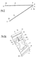
Fig. 1 mit unterschiedlich eingestellten Winkeln. - Fig. 5
- zeigt einen Querschnitt eines anderen Kantenputzprofils, das nicht beansprucht ist.
- Fig. 6a
- ist eine perspektivische Darstellung eines ersten Profilschenkels gemäß einer Ausführungsform der Erfindung.
- Fig. 6b
- ist eine perspektivische Darstellung eines ersten Profilschenkels gemäß einer weiteren Ausführungsform der Erfindung.
- Fig. 7
- ist eine perspektivische Darstellung eines Kantenputzprofils mit Profilschenkeln gemäß
Fig. 6a . - Fig. 8a
- ist eine vergrößerte Schnittdarstellung einer Scharnierbuchse eines Profilschenkels gemäß einer weiteren Ausführungsform der Erfindung.
- Fig. 8b
- ist eine vergrößerte Schnittdarstellung einer Scharnierachse eines Profilschenkels passend zu der Scharnierbuchse nach
Fig. 8a . - Fig. 8c
- ist eine vergrößerte Schnittdarstellung einer Scharnierbuchse eines Profilschenkels gemäß einer weiteren Ausführungsform der Erfindung.
- Fig. 8d
- ist eine vergrößerte Schnittdarstellung einer Scharnierachse eines Profilschenkels passend zu der Scharnierbuchse nach
Fig. 8c . - Fig. 8e
- ist eine vergrößerte Schnittdarstellung einer Scharnierbuchse eines Profilschenkels gemäß einer weiteren Ausführungsform der Erfindung.
- Fig. 8f
- ist eine vergrößerte Schnittdarstellung einer Scharnierachse eines Profilschenkels passend zu der Scharnierbuchse nach
Fig. 8e . - Fig. 9
- ist eine ausschnittsweise Querschnittsansicht eines Kantenputzprofils mit einer Scharnierachse gemäß
Fig. 8d und einer Scharnierbuchse gemäßFig. 8c mit unterschiedlich eingestellten Winkeln. - Fig. 10
- ist eine ausschnittsweise Querschnittsansicht eines Kantenputzprofils mit einer Scharnierachse gemäß
Fig. 8f und einer Scharnierbuchse gemäßFig. 8e mit unterschiedlich eingestellten Winkeln. - Fig. 11
- ist eine Querschnittsansicht des Kantenputzprofils gemäß
Fig. 7 in vollständig zusammengeklapptem Zustand. - Fig. 12
- ist eine Querschnittsansicht des Kantenputzprofils mit einer Scharnierachse gemäß
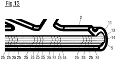
Fig. 8d und einer Scharnierbuchse gemäßFig. 8c in nicht ganz zusammengeklapptem Zustand. - Fig. 13
- ist eine perspektivische Darstellung einer Scharnierbuchse nach
Fig. 8c . - Fig. 14a
- eine erste Seitenansicht eines Sets bestehend aus einem erfindungsgemäßen Kantenputzprofil und einer Justierlehre für das Kantenputzprofil.
- Fig. 14b
- eine zweite Seitenansicht des Sets gemäß
Fig. 14a . - Fig. 14c
- eine dritte Seitenansicht des Sets gemäß
Fig. 14a . - Fig. 14d
- eine vierte Seitenansicht des Sets gemäß
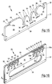
Fig. 14a . - Fig. 15
- eine perspektivische Ansicht der Justierlehre des Sets gemäß
Fig. 14a . - Fig. 16
- eine perspektivische Ansicht einer alternativ ausgebildeten Justierlehre.
- Fig. 1
- is a side view of a section of a profile leg of an edge trim profile, which is not claimed.
- Fig. 2
- shows a cross section of the edge trim profile
Fig. 1 . - Fig. 3
- is a perspective view of the edge trim profile according to
Fig. 1 . - Fig. 4
- is a representation of several cross sections of the edge trim profile according to
Fig. 1 with differently set angles. - Fig. 5
- shows a cross-section of another edge trim profile that is not claimed.
- Figure 6a
- is a perspective view of a first profile leg according to an embodiment of the invention.
- Figure 6b
- is a perspective view of a first profile leg according to a further embodiment of the invention.
- Fig. 7
- is a perspective view of an edge trim profile with profile legs according to
Figure 6a . - Figure 8a
- is an enlarged sectional view of a hinge bushing of a profile leg according to a further embodiment of the invention.
- Figure 8b
- FIG. 12 is an enlarged sectional view of a hinge axis of a profile leg matching the hinge bushing according to FIG
Figure 8a . - Figure 8c
- is an enlarged sectional view of a hinge bushing of a profile leg according to a further embodiment of the invention.
- Figure 8d
- FIG. 12 is an enlarged sectional view of a hinge axis of a profile leg matching the hinge bushing according to FIG
Figure 8c . - Figure 8e
- is an enlarged sectional view of a hinge bushing of a profile leg according to a further embodiment of the invention.
- Fig. 8f
- FIG. 12 is an enlarged sectional view of a hinge axis of a profile leg matching the hinge bushing according to FIG
Figure 8e . - Fig. 9
- FIG. 13 is a partial cross-sectional view of an edge trim profile with a hinge axis according to FIG
Figure 8d and a hinge bushing according toFigure 8c with differently set angles. - Fig. 10
- FIG. 13 is a partial cross-sectional view of an edge trim profile with a hinge axis according to FIG
Fig. 8f and a hinge bushing according toFigure 8e with differently set angles. - Fig. 11
- Figure 13 is a cross-sectional view of the edge trim profile according to
Fig. 7 when fully collapsed. - Fig. 12
- FIG. 13 is a cross-sectional view of the edge trim profile with a hinge axis according to FIG
Figure 8d and a hinge bushing according toFigure 8c when not completely folded up. - Fig. 13
- FIG. 13 is a perspective view of a hinge bushing according to FIG
Figure 8c . - Figure 14a
- a first side view of a set consisting of an edge plaster profile according to the invention and an adjustment gauge for the edge plaster profile.
- Figure 14b
- a second side view of the set according to
Figure 14a . - Figure 14c
- a third side view of the set according to
Figure 14a . - Figure 14d
- a fourth side view of the set according to
Figure 14a . - Fig. 15
- a perspective view of the adjustment gauge of the set according to FIG
Figure 14a . - Fig. 16
- a perspective view of an alternatively designed adjustment gauge.
In den
Wie insbesondere aus
Wie in
Wie in
Die
Wie in
In den
In
Unabhängig von der jeweiligen konkreten Form der Scharnierbuchse und der Scharnierachse weist der erste Profilschenkel 2 bevorzugt zusätzlich zu der am Verbindungsabschnitt 6 vorgesehenen Scharnierachse 10 eine Scharnierbuchse 11 auf, welche entlang der Distal-Längskante 5 verläuft. Gleichzeitig kann der zweite Profilschenkel 8 zusätzlich zu der entlang seiner Eck-Längskante 4 verlaufenden Scharnierbuchse 11 entlang seiner Distal-Längskante 5 eine Scharnierachse 10 aufweisen. In diesem Fall kann in einem zusammengeklappten Zustand des Kantenputzprofils 1, wie in
Bei der in der
Eine andere Variante, die in
Bei der in
In den
Die
Die in
Bei der in der
Zur Einstellung eines gewünschten Winkels zwischen den Profilschenkeln 2, 8 wird das Kantenputzprofil 1 zunächst aufgeklappt und der erste Profilschenkel 2 in der Fixieraufnahme 31 der Justierlehre 26 eingesetzt und an dem Vorsprung 33 eingehakt, beispielsweise mit einer an der Distal-Längskante 5 des ersten Profilschenkels 2 ausgebildeten Scharnierbuchse 11. Der zweite Profilschenkel 8 wird in eine der Justieraufnahmen 32 der Justierlehre 26 eingesetzt, wodurch der Winkel zwischen den Profilschenkeln 2, 8 festgelegt wird, wobei das Einsetzen des zweiten Profilschenkels 8 durch die Abrundungen 35 der Öffnungen 34 erleichtert wird. Abhängig davon, in welcher der Justieraufnahmen 32 der zweite Profilschenkel 8 eingesetzt wird, wird ein anderer Winkel zwischen den Profilschenkeln 2, 8 eingestellt. Wenn der erste Profilschenkel 2 in der Fixieraufnahme 31 und der zweite Profilschenkel 8 in einer der Justieraufnahmen 32 aufgenommen sind, wird die Justierlehre 26 entlang der Längsrichtung L des Kantenputzprofils 1 bewegt, wodurch sich entlang der gesamten Länge des Kantenputzprofils 1 zuverlässig der durch den Abstand von Fixieraufnahme 31 und Justieraufnahme 32 festgelegte Winkel einstellen lässt. Zur leichteren Handhabung ist bei der in der
Es ist auch möglich, einen Profilschenkel 2, wie in den
- 11
- KantenputzprofilEdge plaster profile
- 22
- erster Profilschenkelfirst profile leg
- 33
- SchenkelflächeThigh area
- 44th
- Eck-LängskanteLong corner edge
- 55
- Distal-LängskanteDistal longitudinal edge
- 66th
- VerbindungsabschnittConnection section
- 77th
- Durchbruchbreakthrough
- 88th
- zweiter Profilschenkelsecond profile leg
- 99
- Scharnierhinge
- 1010
- ScharnierachseHinge axis
- 1111
- ScharnierbuchseHinge bushing
- 1212
- erstes Rastmittelfirst locking means
- 1313
- BuchseninnenseiteSocket inside
- 1414th
- zweites Rastmittelsecond locking means
- 1515th
- Fixiermittelfixer
- 1616
- HalteabschnittHolding section
- 1717th
- GegenabschnittOpposite section
- 1818th
- FilmscharnierFilm hinge
- 1919th
- Stegweb
- 2020th
- Flanschflange
- 2121st
- Wändewalls
- 2222nd
- KanteEdge
- 2323
- seitliche Vorsprüngelateral protrusions
- 2424
- HohlkammerHollow chamber
- 2525th
- SicherungsmittelSecuring means
- 2626th
- JustierlehreAdjustment gauge
- 2727
- GrundkörperBase body
- 2828
- JustierseiteAdjustment page
- 2929
- GriffseiteHandle side
- 3030th
- GriffflächeGrip surface
- 3131
- FixieraufnahmeFixation mount
- 3232
- JustieraufnahmeAdjustment holder
- 3333
- Vorsprunghead Start
- 33a33a
- HinterschneidungUndercut
- 3434
- AufnahmeöffnungReceiving opening
- 3535
- AbrundungRounding off
- 3636
- Beschriftunglabeling
- 3737
- DurchgrifföffnungAccess opening
- LL.
- LängsrichtungLongitudinal direction
- dd
- Dickethickness
- ww
- Länge der GriffseiteLength of the handle side
Claims (13)
- A section limb (2) for forming an edge plaster section (1), wherein the section limb (2) has a limb surface (3), wherein the limb surface (3) is bounded at oppositely disposed ends by a corner longitudinal edge (4) and by a distal longitudinal edge (5), and wherein the section limb (2) has a connection section (6) along its corner longitudinal edge (4),
characterized in that
the section limb (2) has a hinge pin (10) at the connection section (6) and has a hinge bushing (11) at the distal longitudinal edge (5). - A section limb (2) in accordance with claim 1,
characterized in that
a division aid along which the section limb (2) is divisible, preferably in the longitudinal direction, is provided between the corner longitudinal edge (4) and the distal longitudinal edge (5). - An edge plaster section (1) comprising a first section limb (2) in accordance with claim 1 or claim 2; and a second section limb (8) which has a limb surface (3) which is bounded at oppositely disposed ends by a corner longitudinal edge (4) and by a distal longitudinal edge (5) and which has a connection section (6) along its corner longitudinal edge (4),
wherein the connection sections (6) of the two section limbs (2, 8) are connected to one another by a hinge (9) which is configured to set and fix an angle between the section limbs (2, 8). - An edge plaster section (1) in accordance with claim 3,
characterized in that
the edge plaster section (1) is substantially or completely composed of plastic,
or
is substantially or completely composed of metal,
or
is composed of a combination of plastic and metal. - An edge plaster section (1) in accordance with claim 3 or claim 4, characterized in that
the edge plaster section (1) can be folded together, in particular completely or approximately completely folded together, by the hinge (9),
with a minimum angle of between 0° and 30°, advantageously of between 0° and 20°, in particular of between 0° and 10°, preferably of substantially 0° or exactly 0°, can be set by the hinge (9) between the first section limb (2) and the second section limb (8). - An edge plaster section (1) in accordance with at least one of the claims 3 to 5,
characterized in that
the second section limb (8) has a hinge bushing (11) at the connection section, which hinge bushing (11) engages with shape matching around the hinge pin (10) of the first section limb (2),
with the second section limb (8) preferably having a hinge pin (10) at the distal longitudinal edge (5). - An edge plaster section (1) in accordance with claim 6,
characterized in that
a force-transmitting connection is formed between the hinge bushing (11) of the second section limb (8) and the hinge pin (10) of the first section limb (2) in order to fix an angle formed between the two section limbs (2, 8);
and/or in that
the hinge pin (10) of the first section limb (2) is clipped into or pushed into the hinge bushing (11) of the second section limb (8);
and/or in that
the hinge pin (10) of the first section limb (2) has a first latching means (12) and the hinge bushing (11) of the second section limb (8) has a second latching means (14) at an inner bushing side (13) which can latch with the first latching means (12) when the hinge pin (10) is arranged in the hinge bushing (11). - An edge plaster section (1) in accordance with claim 6 or claim 7, characterized in that
the corner longitudinal edge (4) of the first section limb (2) is at least substantially identical to the distal longitudinal edge (5) of the second section limb (8); and/or in that the corner longitudinal edge (4) of the second section limb (8) is at least substantially identical to the distal longitudinal edge (5) of the first section limb (2),
in particular in that the first section limb (2) and the second section limb (8) are at least substantially identical,
preferably with, in a completely folded-together state of the edge plaster section (1), the hinge pin (10) of the first section limb (2) being arranged in the hinge bushing (11) of the second section limb (8) and the hinge pin (10) of the second section limb (8) being arranged in the hinge bushing (11) of the first section limb (2). - An edge plaster section (1) in accordance with at least one of the claims 3 to 8,
characterized in that
the limb surfaces (3) of the first and second section limbs (2, 8) have at least one aperture (7) and in particular each have a plurality of apertures (7). - An edge plaster section (1) in accordance with at least one of the claims 3 to 9,
characterized in that
a fixing means (15) is provided by which the angle set and fixed by the hinge (9) can be permanently fixed,
preferably with the fixing means (15) being configured as a spacer, in particular as a web-shaped spacer, and the spacer having at least one holding section (16) which, to fix the set angle, is couplable to a counter-section (17) which is formed at one of the section limbs (2, 8) and which is preferably configured as a fixing aperture formed in the section limb (2, 8), with the fixing means (15) in particular having at least two oppositely disposed holding sections (16). - An edge plaster section (1) in accordance with claim 10,
characterized in that
the fixing means (15) is fixedly but pivotably attached at one end, in particular by a film hinge (18), to one of the section limbs (2, 8);
and/or in that
the fixing means (15) is configured as a fixing means (15) which can break out and which is integrated in at least one of the limb surfaces (3). - Use of a section limb (2) in accordance with claim 1 or claim 2 for producing an edge plaster section (1), in particular an edge plaster section (1) in accordance with at least one of the claims 3 to 11,
characterized in that
the section limb (2) is divided between the corner longitudinal edge (4) and the distal longitudinal edge (5), preferably in the longitudinal direction, and the hinge pin (10) is inserted into the hinge bushing (11) in order to produce the edge plaster section (1). - Use of an edge plaster section (1) in accordance with at least one of the claims 3 to 11, in which the edge plaster section (1) is stored and/or transported folded together, is unfolded before an attachment to an edge (22) to be plastered until a desired angle is set and fixed between the section limbs (2, 8), and is subsequently applied to the edge (22) in the unfolded state.
Applications Claiming Priority (2)
| Application Number | Priority Date | Filing Date | Title |
|---|---|---|---|
| DE102016120908.2A DE102016120908A1 (en) | 2016-11-02 | 2016-11-02 | Edges flush profile |
| PCT/EP2017/077434 WO2018083003A2 (en) | 2016-11-02 | 2017-10-26 | Plaster edge bead, bead limb and adjustment gauge for a plaster edge bead |
Publications (2)
| Publication Number | Publication Date |
|---|---|
| EP3408467A2 EP3408467A2 (en) | 2018-12-05 |
| EP3408467B1 true EP3408467B1 (en) | 2020-09-09 |
Family
ID=60186293
Family Applications (1)
| Application Number | Title | Priority Date | Filing Date |
|---|---|---|---|
| EP17791072.6A Active EP3408467B1 (en) | 2016-11-02 | 2017-10-26 | Bead limb and plaster edge bead |
Country Status (4)
| Country | Link |
|---|---|
| EP (1) | EP3408467B1 (en) |
| DE (1) | DE102016120908A1 (en) |
| PL (1) | PL3408467T3 (en) |
| WO (1) | WO2018083003A2 (en) |
Family Cites Families (9)
| Publication number | Priority date | Publication date | Assignee | Title |
|---|---|---|---|---|
| US2859445A (en) * | 1955-03-09 | 1958-11-11 | Robert C Larrabee | Corner bead applying apparatus |
| DE964348C (en) * | 1955-03-15 | 1957-05-23 | Maisch Ohg Florenz | Plaster strip with fastening legs made of expanded metal, in particular corner protection strip |
| GB9326294D0 (en) * | 1993-12-23 | 1994-02-23 | Condale Plastics Limited | Beading |
| FR2802229B3 (en) * | 1999-12-10 | 2001-10-19 | Profimo | ANGLE PROTECTION DEVICE FOR THE CONSTRUCTION OF WALLS, PARTITIONS, WALLS AND THE LIKE IN THE FIELD OF BUILDING IN COMPLEMENT OF EXTERIOR SINGLE-LAYER PLASTERS |
| EP1331324A3 (en) * | 2002-01-24 | 2004-03-31 | Roman Zahner | Edge-protecting border |
| DE202004003944U1 (en) * | 2004-03-13 | 2004-05-27 | Fiedler, Karl-Heinz | Flooring strip for bridging a joint between two floor coverings comprises a base profile rail, a connecting part, and a hinged cover rail |
| US20070022688A1 (en) * | 2005-06-22 | 2007-02-01 | Dan Fisher | Adjustable corner bead |
| DE202009018128U1 (en) * | 2008-06-17 | 2011-02-10 | Weroform Gmbh | angle section |
| NL1040481C2 (en) * | 2013-11-04 | 2015-05-07 | Ripstaal B V | FOLDABLE ARCHITECTURAL PLATE ELEMENT. |
-
2016
- 2016-11-02 DE DE102016120908.2A patent/DE102016120908A1/en not_active Withdrawn
-
2017
- 2017-10-26 WO PCT/EP2017/077434 patent/WO2018083003A2/en active Application Filing
- 2017-10-26 EP EP17791072.6A patent/EP3408467B1/en active Active
- 2017-10-26 PL PL17791072.6T patent/PL3408467T3/en unknown
Non-Patent Citations (1)
| Title |
|---|
| None * |
Also Published As
| Publication number | Publication date |
|---|---|
| WO2018083003A3 (en) | 2018-06-28 |
| WO2018083003A2 (en) | 2018-05-11 |
| PL3408467T3 (en) | 2021-02-22 |
| DE102016120908A1 (en) | 2018-05-03 |
| EP3408467A2 (en) | 2018-12-05 |
Similar Documents
| Publication | Publication Date | Title |
|---|---|---|
| DE2328385C2 (en) | Expansion anchor | |
| EP1869334B1 (en) | Slide bearing, slide bearing system and assembly of a slide bearing system | |
| DE19828059C2 (en) | Connection fitting with a fastening projection divided by slots in retaining tongues | |
| DE1291561B (en) | Fastener | |
| DE3712478C1 (en) | Corner connector for connecting two miter-cut hollow chamber profiles | |
| DE2613915C2 (en) | Blind rivet | |
| EP1297596B1 (en) | Connecting fitting with an elastic ring as a stop | |
| WO1996016607A1 (en) | Securing element for osteosynthesis | |
| DE2520115B2 (en) | SPREADABLE METAL DOWEL SLEEVE | |
| EP3612698A1 (en) | Hinge for a switchgear cabinet housing and corresponding switchgear cabinet housing and mounting method | |
| DE102014118368B3 (en) | Method and device for producing a corner joint | |
| DE3309844C2 (en) | ||
| DE19539862C2 (en) | Corner connection for hollow section bars to form frame parts | |
| DE69828298T2 (en) | DEVICES FOR MANUFACTURING A CONNECTION | |
| WO2018104283A1 (en) | Fastening element for fastening a seat cover in a hooking-in channel of a seat structure | |
| EP3408467B1 (en) | Bead limb and plaster edge bead | |
| DE19750252A1 (en) | Fastening device | |
| AT410121B (en) | CONNECTING ELEMENT FOR FRAME PROFILES | |
| DE4105491C2 (en) | Fastening device | |
| EP1218642B1 (en) | Expanding rivet and method for producing the same | |
| EP1342926B1 (en) | Fastening Device | |
| DE19531016A1 (en) | Rivet for plates and sheets | |
| EP0791759A1 (en) | Quick-release fastener | |
| DE19617653C2 (en) | Connection arrangement with a profile | |
| DE102007036349A1 (en) | Mounting unit for use in vehicle, has fastener grasping through hole of casing with shaft and held in hole in loss-proof manner, where casing has shaft with retaining units engaging behind bore edge and projecting over outer circumference |
Legal Events
| Date | Code | Title | Description |
|---|---|---|---|
| STAA | Information on the status of an ep patent application or granted ep patent |
Free format text: STATUS: UNKNOWN |
|
| STAA | Information on the status of an ep patent application or granted ep patent |
Free format text: STATUS: THE INTERNATIONAL PUBLICATION HAS BEEN MADE |
|
| PUAI | Public reference made under article 153(3) epc to a published international application that has entered the european phase |
Free format text: ORIGINAL CODE: 0009012 |
|
| STAA | Information on the status of an ep patent application or granted ep patent |
Free format text: STATUS: REQUEST FOR EXAMINATION WAS MADE |
|
| 17P | Request for examination filed |
Effective date: 20180830 |
|
| AK | Designated contracting states |
Kind code of ref document: A2 Designated state(s): AL AT BE BG CH CY CZ DE DK EE ES FI FR GB GR HR HU IE IS IT LI LT LU LV MC MK MT NL NO PL PT RO RS SE SI SK SM TR |
|
| AX | Request for extension of the european patent |
Extension state: BA ME |
|
| STAA | Information on the status of an ep patent application or granted ep patent |
Free format text: STATUS: EXAMINATION IS IN PROGRESS |
|
| 17Q | First examination report despatched |
Effective date: 20190718 |
|
| GRAP | Despatch of communication of intention to grant a patent |
Free format text: ORIGINAL CODE: EPIDOSNIGR1 |
|
| STAA | Information on the status of an ep patent application or granted ep patent |
Free format text: STATUS: GRANT OF PATENT IS INTENDED |
|
| DAV | Request for validation of the european patent (deleted) | ||
| DAX | Request for extension of the european patent (deleted) | ||
| INTG | Intention to grant announced |
Effective date: 20200109 |
|
| GRAJ | Information related to disapproval of communication of intention to grant by the applicant or resumption of examination proceedings by the epo deleted |
Free format text: ORIGINAL CODE: EPIDOSDIGR1 |
|
| STAA | Information on the status of an ep patent application or granted ep patent |
Free format text: STATUS: EXAMINATION IS IN PROGRESS |
|
| GRAP | Despatch of communication of intention to grant a patent |
Free format text: ORIGINAL CODE: EPIDOSNIGR1 |
|
| STAA | Information on the status of an ep patent application or granted ep patent |
Free format text: STATUS: GRANT OF PATENT IS INTENDED |
|
| INTC | Intention to grant announced (deleted) | ||
| INTG | Intention to grant announced |
Effective date: 20200320 |
|
| GRAS | Grant fee paid |
Free format text: ORIGINAL CODE: EPIDOSNIGR3 |
|
| GRAA | (expected) grant |
Free format text: ORIGINAL CODE: 0009210 |
|
| STAA | Information on the status of an ep patent application or granted ep patent |
Free format text: STATUS: THE PATENT HAS BEEN GRANTED |
|
| AK | Designated contracting states |
Kind code of ref document: B1 Designated state(s): AL AT BE BG CH CY CZ DE DK EE ES FI FR GB GR HR HU IE IS IT LI LT LU LV MC MK MT NL NO PL PT RO RS SE SI SK SM TR |
|
| REG | Reference to a national code |
Ref country code: GB Ref legal event code: FG4D Free format text: NOT ENGLISH |
|
| REG | Reference to a national code |
Ref country code: AT Ref legal event code: REF Ref document number: 1311751 Country of ref document: AT Kind code of ref document: T Effective date: 20200915 Ref country code: CH Ref legal event code: EP |
|
| REG | Reference to a national code |
Ref country code: CH Ref legal event code: NV Representative=s name: INTELLECTUAL PROPERTY SERVICES GMBH, CH Ref country code: IE Ref legal event code: FG4D Free format text: LANGUAGE OF EP DOCUMENT: GERMAN |
|
| REG | Reference to a national code |
Ref country code: DE Ref legal event code: R096 Ref document number: 502017007223 Country of ref document: DE |
|
| REG | Reference to a national code |
Ref country code: LT Ref legal event code: MG4D |
|
| PG25 | Lapsed in a contracting state [announced via postgrant information from national office to epo] |
Ref country code: NO Free format text: LAPSE BECAUSE OF FAILURE TO SUBMIT A TRANSLATION OF THE DESCRIPTION OR TO PAY THE FEE WITHIN THE PRESCRIBED TIME-LIMIT Effective date: 20201209 Ref country code: BG Free format text: LAPSE BECAUSE OF FAILURE TO SUBMIT A TRANSLATION OF THE DESCRIPTION OR TO PAY THE FEE WITHIN THE PRESCRIBED TIME-LIMIT Effective date: 20201209 Ref country code: SE Free format text: LAPSE BECAUSE OF FAILURE TO SUBMIT A TRANSLATION OF THE DESCRIPTION OR TO PAY THE FEE WITHIN THE PRESCRIBED TIME-LIMIT Effective date: 20200909 Ref country code: HR Free format text: LAPSE BECAUSE OF FAILURE TO SUBMIT A TRANSLATION OF THE DESCRIPTION OR TO PAY THE FEE WITHIN THE PRESCRIBED TIME-LIMIT Effective date: 20200909 Ref country code: GR Free format text: LAPSE BECAUSE OF FAILURE TO SUBMIT A TRANSLATION OF THE DESCRIPTION OR TO PAY THE FEE WITHIN THE PRESCRIBED TIME-LIMIT Effective date: 20201210 Ref country code: LT Free format text: LAPSE BECAUSE OF FAILURE TO SUBMIT A TRANSLATION OF THE DESCRIPTION OR TO PAY THE FEE WITHIN THE PRESCRIBED TIME-LIMIT Effective date: 20200909 Ref country code: FI Free format text: LAPSE BECAUSE OF FAILURE TO SUBMIT A TRANSLATION OF THE DESCRIPTION OR TO PAY THE FEE WITHIN THE PRESCRIBED TIME-LIMIT Effective date: 20200909 |
|
| PGFP | Annual fee paid to national office [announced via postgrant information from national office to epo] |
Ref country code: CH Payment date: 20201021 Year of fee payment: 4 Ref country code: FR Payment date: 20201022 Year of fee payment: 4 |
|
| REG | Reference to a national code |
Ref country code: NL Ref legal event code: MP Effective date: 20200909 |
|
| PG25 | Lapsed in a contracting state [announced via postgrant information from national office to epo] |
Ref country code: RS Free format text: LAPSE BECAUSE OF FAILURE TO SUBMIT A TRANSLATION OF THE DESCRIPTION OR TO PAY THE FEE WITHIN THE PRESCRIBED TIME-LIMIT Effective date: 20200909 Ref country code: LV Free format text: LAPSE BECAUSE OF FAILURE TO SUBMIT A TRANSLATION OF THE DESCRIPTION OR TO PAY THE FEE WITHIN THE PRESCRIBED TIME-LIMIT Effective date: 20200909 |
|
| PG25 | Lapsed in a contracting state [announced via postgrant information from national office to epo] |
Ref country code: SM Free format text: LAPSE BECAUSE OF FAILURE TO SUBMIT A TRANSLATION OF THE DESCRIPTION OR TO PAY THE FEE WITHIN THE PRESCRIBED TIME-LIMIT Effective date: 20200909 Ref country code: EE Free format text: LAPSE BECAUSE OF FAILURE TO SUBMIT A TRANSLATION OF THE DESCRIPTION OR TO PAY THE FEE WITHIN THE PRESCRIBED TIME-LIMIT Effective date: 20200909 Ref country code: PT Free format text: LAPSE BECAUSE OF FAILURE TO SUBMIT A TRANSLATION OF THE DESCRIPTION OR TO PAY THE FEE WITHIN THE PRESCRIBED TIME-LIMIT Effective date: 20210111 Ref country code: RO Free format text: LAPSE BECAUSE OF FAILURE TO SUBMIT A TRANSLATION OF THE DESCRIPTION OR TO PAY THE FEE WITHIN THE PRESCRIBED TIME-LIMIT Effective date: 20200909 Ref country code: CZ Free format text: LAPSE BECAUSE OF FAILURE TO SUBMIT A TRANSLATION OF THE DESCRIPTION OR TO PAY THE FEE WITHIN THE PRESCRIBED TIME-LIMIT Effective date: 20200909 |
|
| PG25 | Lapsed in a contracting state [announced via postgrant information from national office to epo] |
Ref country code: AL Free format text: LAPSE BECAUSE OF FAILURE TO SUBMIT A TRANSLATION OF THE DESCRIPTION OR TO PAY THE FEE WITHIN THE PRESCRIBED TIME-LIMIT Effective date: 20200909 Ref country code: ES Free format text: LAPSE BECAUSE OF FAILURE TO SUBMIT A TRANSLATION OF THE DESCRIPTION OR TO PAY THE FEE WITHIN THE PRESCRIBED TIME-LIMIT Effective date: 20200909 Ref country code: IS Free format text: LAPSE BECAUSE OF FAILURE TO SUBMIT A TRANSLATION OF THE DESCRIPTION OR TO PAY THE FEE WITHIN THE PRESCRIBED TIME-LIMIT Effective date: 20210109 |
|
| PGFP | Annual fee paid to national office [announced via postgrant information from national office to epo] |
Ref country code: PL Payment date: 20201030 Year of fee payment: 4 |
|
| REG | Reference to a national code |
Ref country code: DE Ref legal event code: R097 Ref document number: 502017007223 Country of ref document: DE |
|
| PG25 | Lapsed in a contracting state [announced via postgrant information from national office to epo] |
Ref country code: MC Free format text: LAPSE BECAUSE OF FAILURE TO SUBMIT A TRANSLATION OF THE DESCRIPTION OR TO PAY THE FEE WITHIN THE PRESCRIBED TIME-LIMIT Effective date: 20200909 Ref country code: SK Free format text: LAPSE BECAUSE OF FAILURE TO SUBMIT A TRANSLATION OF THE DESCRIPTION OR TO PAY THE FEE WITHIN THE PRESCRIBED TIME-LIMIT Effective date: 20200909 Ref country code: LU Free format text: LAPSE BECAUSE OF NON-PAYMENT OF DUE FEES Effective date: 20201026 |
|
| REG | Reference to a national code |
Ref country code: BE Ref legal event code: MM Effective date: 20201031 |
|
| PLBE | No opposition filed within time limit |
Free format text: ORIGINAL CODE: 0009261 |
|
| STAA | Information on the status of an ep patent application or granted ep patent |
Free format text: STATUS: NO OPPOSITION FILED WITHIN TIME LIMIT |
|
| 26N | No opposition filed |
Effective date: 20210610 |
|
| PG25 | Lapsed in a contracting state [announced via postgrant information from national office to epo] |
Ref country code: BE Free format text: LAPSE BECAUSE OF NON-PAYMENT OF DUE FEES Effective date: 20201031 Ref country code: SI Free format text: LAPSE BECAUSE OF FAILURE TO SUBMIT A TRANSLATION OF THE DESCRIPTION OR TO PAY THE FEE WITHIN THE PRESCRIBED TIME-LIMIT Effective date: 20200909 Ref country code: DK Free format text: LAPSE BECAUSE OF FAILURE TO SUBMIT A TRANSLATION OF THE DESCRIPTION OR TO PAY THE FEE WITHIN THE PRESCRIBED TIME-LIMIT Effective date: 20200909 |
|
| PG25 | Lapsed in a contracting state [announced via postgrant information from national office to epo] |
Ref country code: IE Free format text: LAPSE BECAUSE OF NON-PAYMENT OF DUE FEES Effective date: 20201026 Ref country code: IT Free format text: LAPSE BECAUSE OF FAILURE TO SUBMIT A TRANSLATION OF THE DESCRIPTION OR TO PAY THE FEE WITHIN THE PRESCRIBED TIME-LIMIT Effective date: 20200909 |
|
| REG | Reference to a national code |
Ref country code: CH Ref legal event code: PL |
|
| PG25 | Lapsed in a contracting state [announced via postgrant information from national office to epo] |
Ref country code: TR Free format text: LAPSE BECAUSE OF FAILURE TO SUBMIT A TRANSLATION OF THE DESCRIPTION OR TO PAY THE FEE WITHIN THE PRESCRIBED TIME-LIMIT Effective date: 20200909 Ref country code: MT Free format text: LAPSE BECAUSE OF FAILURE TO SUBMIT A TRANSLATION OF THE DESCRIPTION OR TO PAY THE FEE WITHIN THE PRESCRIBED TIME-LIMIT Effective date: 20200909 Ref country code: CY Free format text: LAPSE BECAUSE OF FAILURE TO SUBMIT A TRANSLATION OF THE DESCRIPTION OR TO PAY THE FEE WITHIN THE PRESCRIBED TIME-LIMIT Effective date: 20200909 |
|
| GBPC | Gb: european patent ceased through non-payment of renewal fee |
Effective date: 20211026 |
|
| PG25 | Lapsed in a contracting state [announced via postgrant information from national office to epo] |
Ref country code: MK Free format text: LAPSE BECAUSE OF FAILURE TO SUBMIT A TRANSLATION OF THE DESCRIPTION OR TO PAY THE FEE WITHIN THE PRESCRIBED TIME-LIMIT Effective date: 20200909 |
|
| PG25 | Lapsed in a contracting state [announced via postgrant information from national office to epo] |
Ref country code: GB Free format text: LAPSE BECAUSE OF NON-PAYMENT OF DUE FEES Effective date: 20211026 |
|
| PG25 | Lapsed in a contracting state [announced via postgrant information from national office to epo] |
Ref country code: LI Free format text: LAPSE BECAUSE OF NON-PAYMENT OF DUE FEES Effective date: 20211031 Ref country code: CH Free format text: LAPSE BECAUSE OF NON-PAYMENT OF DUE FEES Effective date: 20211031 |
|
| PG25 | Lapsed in a contracting state [announced via postgrant information from national office to epo] |
Ref country code: FR Free format text: LAPSE BECAUSE OF NON-PAYMENT OF DUE FEES Effective date: 20211031 |
|
| PG25 | Lapsed in a contracting state [announced via postgrant information from national office to epo] |
Ref country code: PL Free format text: LAPSE BECAUSE OF NON-PAYMENT OF DUE FEES Effective date: 20211026 |
|
| PGFP | Annual fee paid to national office [announced via postgrant information from national office to epo] |
Ref country code: DE Payment date: 20221228 Year of fee payment: 6 |
|
| P01 | Opt-out of the competence of the unified patent court (upc) registered |
Effective date: 20230522 |
|
| PG25 | Lapsed in a contracting state [announced via postgrant information from national office to epo] |
Ref country code: NL Free format text: LAPSE BECAUSE OF NON-PAYMENT OF DUE FEES Effective date: 20200923 |
|
| PGFP | Annual fee paid to national office [announced via postgrant information from national office to epo] |
Ref country code: AT Payment date: 20231020 Year of fee payment: 7 |