EP3408401B1 - Electrochemiluminescence method and apparatus for detecting an analyte in a liquid sample - Google Patents
Electrochemiluminescence method and apparatus for detecting an analyte in a liquid sample Download PDFInfo
- Publication number
- EP3408401B1 EP3408401B1 EP17702082.3A EP17702082A EP3408401B1 EP 3408401 B1 EP3408401 B1 EP 3408401B1 EP 17702082 A EP17702082 A EP 17702082A EP 3408401 B1 EP3408401 B1 EP 3408401B1
- Authority
- EP
- European Patent Office
- Prior art keywords
- eis
- measurement
- point
- measuring cell
- phase
- Prior art date
- Legal status (The legal status is an assumption and is not a legal conclusion. Google has not performed a legal analysis and makes no representation as to the accuracy of the status listed.)
- Active
Links
- 238000000034 method Methods 0.000 title claims description 115
- 239000007788 liquid Substances 0.000 title claims description 75
- 239000012491 analyte Substances 0.000 title claims description 61
- 238000000157 electrochemical-induced impedance spectroscopy Methods 0.000 claims description 229
- 238000005259 measurement Methods 0.000 claims description 225
- 239000000243 solution Substances 0.000 claims description 80
- 238000004140 cleaning Methods 0.000 claims description 66
- 238000003556 assay Methods 0.000 claims description 62
- 239000000376 reactant Substances 0.000 claims description 47
- 230000032683 aging Effects 0.000 claims description 31
- 238000004458 analytical method Methods 0.000 claims description 31
- 230000008569 process Effects 0.000 claims description 26
- 239000011859 microparticle Substances 0.000 claims description 19
- 238000006243 chemical reaction Methods 0.000 claims description 14
- 238000004590 computer program Methods 0.000 claims description 10
- 239000000126 substance Substances 0.000 claims description 10
- 239000011800 void material Substances 0.000 claims description 10
- 230000003750 conditioning effect Effects 0.000 claims description 8
- 230000004044 response Effects 0.000 claims description 7
- 238000005406 washing Methods 0.000 claims description 7
- 239000012670 alkaline solution Substances 0.000 claims description 4
- 238000000151 deposition Methods 0.000 claims description 4
- 230000010287 polarization Effects 0.000 claims description 2
- 210000004027 cell Anatomy 0.000 description 93
- 239000000523 sample Substances 0.000 description 65
- 238000004020 luminiscence type Methods 0.000 description 26
- 239000011324 bead Substances 0.000 description 21
- 238000003860 storage Methods 0.000 description 17
- 239000003153 chemical reaction reagent Substances 0.000 description 13
- 230000000694 effects Effects 0.000 description 13
- 238000003018 immunoassay Methods 0.000 description 11
- 238000010586 diagram Methods 0.000 description 10
- 230000006870 function Effects 0.000 description 10
- BASFCYQUMIYNBI-UHFFFAOYSA-N platinum Chemical compound [Pt] BASFCYQUMIYNBI-UHFFFAOYSA-N 0.000 description 10
- 210000002966 serum Anatomy 0.000 description 10
- 108010090804 Streptavidin Proteins 0.000 description 8
- 230000008859 change Effects 0.000 description 8
- 230000001788 irregular Effects 0.000 description 8
- 238000001228 spectrum Methods 0.000 description 8
- YFTHZRPMJXBUME-UHFFFAOYSA-N tripropylamine Chemical compound CCCN(CCC)CCC YFTHZRPMJXBUME-UHFFFAOYSA-N 0.000 description 8
- 230000005284 excitation Effects 0.000 description 7
- 230000003287 optical effect Effects 0.000 description 7
- KWYUFKZDYYNOTN-UHFFFAOYSA-M Potassium hydroxide Chemical compound [OH-].[K+] KWYUFKZDYYNOTN-UHFFFAOYSA-M 0.000 description 6
- 238000011109 contamination Methods 0.000 description 6
- QSHDDOUJBYECFT-UHFFFAOYSA-N mercury Chemical compound [Hg] QSHDDOUJBYECFT-UHFFFAOYSA-N 0.000 description 6
- 229910052753 mercury Inorganic materials 0.000 description 6
- 239000002245 particle Substances 0.000 description 6
- 238000009739 binding Methods 0.000 description 5
- 238000001514 detection method Methods 0.000 description 5
- PCHJSUWPFVWCPO-UHFFFAOYSA-N gold Chemical compound [Au] PCHJSUWPFVWCPO-UHFFFAOYSA-N 0.000 description 5
- 229910052737 gold Inorganic materials 0.000 description 5
- 239000010931 gold Substances 0.000 description 5
- 239000006249 magnetic particle Substances 0.000 description 5
- 229910052697 platinum Inorganic materials 0.000 description 5
- 238000012545 processing Methods 0.000 description 5
- 239000000872 buffer Substances 0.000 description 4
- 230000002452 interceptive effect Effects 0.000 description 4
- 239000000203 mixture Substances 0.000 description 4
- 108090000623 proteins and genes Proteins 0.000 description 4
- 102000004169 proteins and genes Human genes 0.000 description 4
- 229910052709 silver Inorganic materials 0.000 description 4
- 239000004332 silver Substances 0.000 description 4
- 238000001378 electrochemiluminescence detection Methods 0.000 description 3
- 238000002474 experimental method Methods 0.000 description 3
- 238000011065 in-situ storage Methods 0.000 description 3
- 238000001179 sorption measurement Methods 0.000 description 3
- 230000002269 spontaneous effect Effects 0.000 description 3
- 229910001220 stainless steel Inorganic materials 0.000 description 3
- 239000010935 stainless steel Substances 0.000 description 3
- YBJHBAHKTGYVGT-ZKWXMUAHSA-N (+)-Biotin Chemical compound N1C(=O)N[C@@H]2[C@H](CCCCC(=O)O)SC[C@@H]21 YBJHBAHKTGYVGT-ZKWXMUAHSA-N 0.000 description 2
- CHEANNSDVJOIBS-MHZLTWQESA-N (3s)-3-cyclopropyl-3-[3-[[3-(5,5-dimethylcyclopenten-1-yl)-4-(2-fluoro-5-methoxyphenyl)phenyl]methoxy]phenyl]propanoic acid Chemical compound COC1=CC=C(F)C(C=2C(=CC(COC=3C=C(C=CC=3)[C@@H](CC(O)=O)C3CC3)=CC=2)C=2C(CCC=2)(C)C)=C1 CHEANNSDVJOIBS-MHZLTWQESA-N 0.000 description 2
- DOBUSJIVSSJEDA-UHFFFAOYSA-L 1,3-dioxa-2$l^{6}-thia-4-mercuracyclobutane 2,2-dioxide Chemical compound [Hg+2].[O-]S([O-])(=O)=O DOBUSJIVSSJEDA-UHFFFAOYSA-L 0.000 description 2
- ZOXJGFHDIHLPTG-UHFFFAOYSA-N Boron Chemical compound [B] ZOXJGFHDIHLPTG-UHFFFAOYSA-N 0.000 description 2
- RYGMFSIKBFXOCR-UHFFFAOYSA-N Copper Chemical compound [Cu] RYGMFSIKBFXOCR-UHFFFAOYSA-N 0.000 description 2
- 229920001363 Polidocanol Polymers 0.000 description 2
- BQCADISMDOOEFD-UHFFFAOYSA-N Silver Chemical compound [Ag] BQCADISMDOOEFD-UHFFFAOYSA-N 0.000 description 2
- 229910021607 Silver chloride Inorganic materials 0.000 description 2
- 239000013543 active substance Substances 0.000 description 2
- 230000006399 behavior Effects 0.000 description 2
- 230000008901 benefit Effects 0.000 description 2
- 239000012472 biological sample Substances 0.000 description 2
- 229910052796 boron Inorganic materials 0.000 description 2
- 239000007853 buffer solution Substances 0.000 description 2
- 238000004364 calculation method Methods 0.000 description 2
- 210000005056 cell body Anatomy 0.000 description 2
- 238000004891 communication Methods 0.000 description 2
- 229910052802 copper Inorganic materials 0.000 description 2
- 239000010949 copper Substances 0.000 description 2
- 229910000365 copper sulfate Inorganic materials 0.000 description 2
- ARUVKPQLZAKDPS-UHFFFAOYSA-L copper(II) sulfate Chemical compound [Cu+2].[O-][S+2]([O-])([O-])[O-] ARUVKPQLZAKDPS-UHFFFAOYSA-L 0.000 description 2
- 230000008021 deposition Effects 0.000 description 2
- 239000003599 detergent Substances 0.000 description 2
- 229910003460 diamond Inorganic materials 0.000 description 2
- 239000010432 diamond Substances 0.000 description 2
- ZOMNIUBKTOKEHS-UHFFFAOYSA-L dimercury dichloride Chemical class Cl[Hg][Hg]Cl ZOMNIUBKTOKEHS-UHFFFAOYSA-L 0.000 description 2
- 238000003487 electrochemical reaction Methods 0.000 description 2
- 238000011156 evaluation Methods 0.000 description 2
- 229910021397 glassy carbon Inorganic materials 0.000 description 2
- 230000000977 initiatory effect Effects 0.000 description 2
- 229910052741 iridium Inorganic materials 0.000 description 2
- GKOZUEZYRPOHIO-UHFFFAOYSA-N iridium atom Chemical compound [Ir] GKOZUEZYRPOHIO-UHFFFAOYSA-N 0.000 description 2
- 239000003550 marker Substances 0.000 description 2
- 239000000463 material Substances 0.000 description 2
- 229910000370 mercury sulfate Inorganic materials 0.000 description 2
- 230000010363 phase shift Effects 0.000 description 2
- ONJQDTZCDSESIW-UHFFFAOYSA-N polidocanol Chemical compound CCCCCCCCCCCCOCCOCCOCCOCCOCCOCCOCCOCCOCCO ONJQDTZCDSESIW-UHFFFAOYSA-N 0.000 description 2
- 229960002226 polidocanol Drugs 0.000 description 2
- 230000000644 propagated effect Effects 0.000 description 2
- 230000008929 regeneration Effects 0.000 description 2
- 238000011069 regeneration method Methods 0.000 description 2
- YAYGSLOSTXKUBW-UHFFFAOYSA-N ruthenium(2+) Chemical compound [Ru+2] YAYGSLOSTXKUBW-UHFFFAOYSA-N 0.000 description 2
- HKZLPVFGJNLROG-UHFFFAOYSA-M silver monochloride Chemical compound [Cl-].[Ag+] HKZLPVFGJNLROG-UHFFFAOYSA-M 0.000 description 2
- 241000894007 species Species 0.000 description 2
- 239000000725 suspension Substances 0.000 description 2
- 238000012360 testing method Methods 0.000 description 2
- BZSVVCFHMVMYCR-UHFFFAOYSA-N 2-pyridin-2-ylpyridine;ruthenium Chemical compound [Ru].N1=CC=CC=C1C1=CC=CC=N1.N1=CC=CC=C1C1=CC=CC=N1.N1=CC=CC=C1C1=CC=CC=N1 BZSVVCFHMVMYCR-UHFFFAOYSA-N 0.000 description 1
- 238000012935 Averaging Methods 0.000 description 1
- 101100027969 Caenorhabditis elegans old-1 gene Proteins 0.000 description 1
- MUBZPKHOEPUJKR-UHFFFAOYSA-N Oxalic acid Chemical compound OC(=O)C(O)=O MUBZPKHOEPUJKR-UHFFFAOYSA-N 0.000 description 1
- 229910019142 PO4 Inorganic materials 0.000 description 1
- 239000004793 Polystyrene Substances 0.000 description 1
- 239000012327 Ruthenium complex Substances 0.000 description 1
- 239000005708 Sodium hypochlorite Substances 0.000 description 1
- 241000700605 Viruses Species 0.000 description 1
- 230000009471 action Effects 0.000 description 1
- 230000006978 adaptation Effects 0.000 description 1
- 230000002776 aggregation Effects 0.000 description 1
- 238000004220 aggregation Methods 0.000 description 1
- 150000001412 amines Chemical class 0.000 description 1
- 230000002547 anomalous effect Effects 0.000 description 1
- 229960002685 biotin Drugs 0.000 description 1
- 235000020958 biotin Nutrition 0.000 description 1
- 239000011616 biotin Substances 0.000 description 1
- 210000001124 body fluid Anatomy 0.000 description 1
- 239000010839 body fluid Substances 0.000 description 1
- 238000011088 calibration curve Methods 0.000 description 1
- 230000032677 cell aging Effects 0.000 description 1
- 239000004020 conductor Substances 0.000 description 1
- 238000012937 correction Methods 0.000 description 1
- 230000008878 coupling Effects 0.000 description 1
- 238000010168 coupling process Methods 0.000 description 1
- 238000005859 coupling reaction Methods 0.000 description 1
- 230000003247 decreasing effect Effects 0.000 description 1
- 230000007547 defect Effects 0.000 description 1
- 238000001212 derivatisation Methods 0.000 description 1
- 238000011161 development Methods 0.000 description 1
- 230000018109 developmental process Effects 0.000 description 1
- 239000003814 drug Substances 0.000 description 1
- 230000005684 electric field Effects 0.000 description 1
- 230000005281 excited state Effects 0.000 description 1
- 238000004401 flow injection analysis Methods 0.000 description 1
- 239000012530 fluid Substances 0.000 description 1
- 230000007274 generation of a signal involved in cell-cell signaling Effects 0.000 description 1
- 230000005283 ground state Effects 0.000 description 1
- 238000004128 high performance liquid chromatography Methods 0.000 description 1
- 239000005556 hormone Substances 0.000 description 1
- 229940088597 hormone Drugs 0.000 description 1
- 238000001453 impedance spectrum Methods 0.000 description 1
- 239000010808 liquid waste Substances 0.000 description 1
- 239000002122 magnetic nanoparticle Substances 0.000 description 1
- 230000007257 malfunction Effects 0.000 description 1
- 238000004519 manufacturing process Methods 0.000 description 1
- 239000002207 metabolite Substances 0.000 description 1
- 244000005700 microbiome Species 0.000 description 1
- 102000039446 nucleic acids Human genes 0.000 description 1
- 108020004707 nucleic acids Proteins 0.000 description 1
- 150000007523 nucleic acids Chemical class 0.000 description 1
- 239000013307 optical fiber Substances 0.000 description 1
- NBIIXXVUZAFLBC-UHFFFAOYSA-K phosphate Chemical compound [O-]P([O-])([O-])=O NBIIXXVUZAFLBC-UHFFFAOYSA-K 0.000 description 1
- 239000010452 phosphate Substances 0.000 description 1
- 229920002223 polystyrene Polymers 0.000 description 1
- 238000003908 quality control method Methods 0.000 description 1
- 230000005855 radiation Effects 0.000 description 1
- 238000006479 redox reaction Methods 0.000 description 1
- 230000003252 repetitive effect Effects 0.000 description 1
- 238000011160 research Methods 0.000 description 1
- 238000005316 response function Methods 0.000 description 1
- 238000005070 sampling Methods 0.000 description 1
- 238000000926 separation method Methods 0.000 description 1
- SUKJFIGYRHOWBL-UHFFFAOYSA-N sodium hypochlorite Chemical compound [Na+].Cl[O-] SUKJFIGYRHOWBL-UHFFFAOYSA-N 0.000 description 1
- 239000007787 solid Substances 0.000 description 1
- 230000000638 stimulation Effects 0.000 description 1
- 210000003813 thumb Anatomy 0.000 description 1
- 230000036962 time dependent Effects 0.000 description 1
- 230000001960 triggered effect Effects 0.000 description 1
Images


Classifications
-
- G—PHYSICS
- G01—MEASURING; TESTING
- G01N—INVESTIGATING OR ANALYSING MATERIALS BY DETERMINING THEIR CHEMICAL OR PHYSICAL PROPERTIES
- G01N21/00—Investigating or analysing materials by the use of optical means, i.e. using sub-millimetre waves, infrared, visible or ultraviolet light
- G01N21/62—Systems in which the material investigated is excited whereby it emits light or causes a change in wavelength of the incident light
- G01N21/66—Systems in which the material investigated is excited whereby it emits light or causes a change in wavelength of the incident light electrically excited, e.g. electroluminescence
-
- C—CHEMISTRY; METALLURGY
- C12—BIOCHEMISTRY; BEER; SPIRITS; WINE; VINEGAR; MICROBIOLOGY; ENZYMOLOGY; MUTATION OR GENETIC ENGINEERING
- C12Q—MEASURING OR TESTING PROCESSES INVOLVING ENZYMES, NUCLEIC ACIDS OR MICROORGANISMS; COMPOSITIONS OR TEST PAPERS THEREFOR; PROCESSES OF PREPARING SUCH COMPOSITIONS; CONDITION-RESPONSIVE CONTROL IN MICROBIOLOGICAL OR ENZYMOLOGICAL PROCESSES
- C12Q1/00—Measuring or testing processes involving enzymes, nucleic acids or microorganisms; Compositions therefor; Processes of preparing such compositions
-
- G—PHYSICS
- G01—MEASURING; TESTING
- G01N—INVESTIGATING OR ANALYSING MATERIALS BY DETERMINING THEIR CHEMICAL OR PHYSICAL PROPERTIES
- G01N21/00—Investigating or analysing materials by the use of optical means, i.e. using sub-millimetre waves, infrared, visible or ultraviolet light
- G01N21/75—Systems in which material is subjected to a chemical reaction, the progress or the result of the reaction being investigated
- G01N21/76—Chemiluminescence; Bioluminescence
- G01N21/763—Bioluminescence
-
- G—PHYSICS
- G01—MEASURING; TESTING
- G01N—INVESTIGATING OR ANALYSING MATERIALS BY DETERMINING THEIR CHEMICAL OR PHYSICAL PROPERTIES
- G01N27/00—Investigating or analysing materials by the use of electric, electrochemical, or magnetic means
- G01N27/26—Investigating or analysing materials by the use of electric, electrochemical, or magnetic means by investigating electrochemical variables; by using electrolysis or electrophoresis
- G01N27/28—Electrolytic cell components
- G01N27/30—Electrodes, e.g. test electrodes; Half-cells
- G01N27/327—Biochemical electrodes, e.g. electrical or mechanical details for in vitro measurements
- G01N27/3275—Sensing specific biomolecules, e.g. nucleic acid strands, based on an electrode surface reaction
- G01N27/3277—Sensing specific biomolecules, e.g. nucleic acid strands, based on an electrode surface reaction being a redox reaction, e.g. detection by cyclic voltammetry
-
- G—PHYSICS
- G01—MEASURING; TESTING
- G01N—INVESTIGATING OR ANALYSING MATERIALS BY DETERMINING THEIR CHEMICAL OR PHYSICAL PROPERTIES
- G01N27/00—Investigating or analysing materials by the use of electric, electrochemical, or magnetic means
- G01N27/26—Investigating or analysing materials by the use of electric, electrochemical, or magnetic means by investigating electrochemical variables; by using electrolysis or electrophoresis
- G01N27/416—Systems
- G01N27/4163—Systems checking the operation of, or calibrating, the measuring apparatus
-
- G—PHYSICS
- G01—MEASURING; TESTING
- G01N—INVESTIGATING OR ANALYSING MATERIALS BY DETERMINING THEIR CHEMICAL OR PHYSICAL PROPERTIES
- G01N33/00—Investigating or analysing materials by specific methods not covered by groups G01N1/00 - G01N31/00
- G01N33/48—Biological material, e.g. blood, urine; Haemocytometers
- G01N33/50—Chemical analysis of biological material, e.g. blood, urine; Testing involving biospecific ligand binding methods; Immunological testing
- G01N33/53—Immunoassay; Biospecific binding assay; Materials therefor
- G01N33/543—Immunoassay; Biospecific binding assay; Materials therefor with an insoluble carrier for immobilising immunochemicals
- G01N33/54366—Apparatus specially adapted for solid-phase testing
- G01N33/54373—Apparatus specially adapted for solid-phase testing involving physiochemical end-point determination, e.g. wave-guides, FETS, gratings
- G01N33/5438—Electrodes
-
- G—PHYSICS
- G01—MEASURING; TESTING
- G01N—INVESTIGATING OR ANALYSING MATERIALS BY DETERMINING THEIR CHEMICAL OR PHYSICAL PROPERTIES
- G01N33/00—Investigating or analysing materials by specific methods not covered by groups G01N1/00 - G01N31/00
- G01N33/48—Biological material, e.g. blood, urine; Haemocytometers
- G01N33/50—Chemical analysis of biological material, e.g. blood, urine; Testing involving biospecific ligand binding methods; Immunological testing
- G01N33/58—Chemical analysis of biological material, e.g. blood, urine; Testing involving biospecific ligand binding methods; Immunological testing involving labelled substances
- G01N33/582—Chemical analysis of biological material, e.g. blood, urine; Testing involving biospecific ligand binding methods; Immunological testing involving labelled substances with fluorescent label
-
- G—PHYSICS
- G01—MEASURING; TESTING
- G01N—INVESTIGATING OR ANALYSING MATERIALS BY DETERMINING THEIR CHEMICAL OR PHYSICAL PROPERTIES
- G01N35/00—Automatic analysis not limited to methods or materials provided for in any single one of groups G01N1/00 - G01N33/00; Handling materials therefor
- G01N35/00584—Control arrangements for automatic analysers
- G01N35/00594—Quality control, including calibration or testing of components of the analyser
- G01N35/00613—Quality control
- G01N35/00623—Quality control of instruments
-
- G—PHYSICS
- G01—MEASURING; TESTING
- G01N—INVESTIGATING OR ANALYSING MATERIALS BY DETERMINING THEIR CHEMICAL OR PHYSICAL PROPERTIES
- G01N35/00—Automatic analysis not limited to methods or materials provided for in any single one of groups G01N1/00 - G01N33/00; Handling materials therefor
- G01N35/00584—Control arrangements for automatic analysers
- G01N35/00722—Communications; Identification
-
- G—PHYSICS
- G01—MEASURING; TESTING
- G01N—INVESTIGATING OR ANALYSING MATERIALS BY DETERMINING THEIR CHEMICAL OR PHYSICAL PROPERTIES
- G01N35/00—Automatic analysis not limited to methods or materials provided for in any single one of groups G01N1/00 - G01N33/00; Handling materials therefor
- G01N35/10—Devices for transferring samples or any liquids to, in, or from, the analysis apparatus, e.g. suction devices, injection devices
- G01N35/1004—Cleaning sample transfer devices
-
- G—PHYSICS
- G01—MEASURING; TESTING
- G01N—INVESTIGATING OR ANALYSING MATERIALS BY DETERMINING THEIR CHEMICAL OR PHYSICAL PROPERTIES
- G01N35/00—Automatic analysis not limited to methods or materials provided for in any single one of groups G01N1/00 - G01N33/00; Handling materials therefor
- G01N35/00584—Control arrangements for automatic analysers
- G01N35/00722—Communications; Identification
- G01N2035/00891—Displaying information to the operator
Definitions
- the invention relates to an electrochemiluminescence method of detecting an analyte in a liquid sample and an apparatus for detecting an analyte in a liquid sample, as well as a computer program product.
- Electrochemiluminescent (ECL) assay techniques are well known for the detection and quantitation of analytes of interest in biochemical and biological substances.
- ECL Electrochemiluminescent
- ECL assay techniques provide a sensitive and precise measurement of the presence and concentration of an analyte of interest.
- the incubated sample is exposed to a potentiostatically or galvanostatically controlled working electrode in order to trigger luminescence.
- electrochemiluminescence is triggered by a voltage or current impressed on the working electrode at a particular time and in a particular manner.
- the light produced by the label is measured and indicates the presence or quantity of the analyte.
- WO 90/11511 discloses a method and an apparatus for conducting electrochemiluminescent measurements using a voltage waveform with a decreasing scan rate applied at a voltammetric working electrode to improve the precision and accuracy of measurements.
- WO 99/39206 a method for analyzing a test sample by means of an electro-chemiluminsecence bond reaction test is described, wherein a complex containing a chemoluminescence marker, which is characteristic for the analysis, is formed through a biochemical bond reaction and bonded to a magnetic microparticle during a reaction sequence.
- Tris (2,2'-bipyridyl)ruthenium(II) Electrogenerated Chemiluminescence in Analytical Science Microchim. Acta 127, 19 - 39, W.-Y .
- a detectable complex is produced, whose concentration constitutes a measure of the analytic result sought.
- a marking substance (label) capable of effecting an ECL-reaction is coupled to a binding reagent specific for the analyte, e.g. an antibody.
- the species comprising the marking substance and the binding reagent is designated as a label conjugate.
- a second electrochemically active substance normally contributes to this reaction.
- a co-reactant normally contributes to this reaction.
- ruthenium complex ruthenium-tris [bipyridyl]
- TPA tripropylamine
- the subsequent redox reaction brings the ECL-label into an excited state from which it returns to the ground state with the emission of a photon.
- the ECL-label reaction is preferably a circular reaction so that a single label molecule emits a plurality of photons after application of a voltage to the electrode.
- the ECL-marked complex molecules characteristic for the analysis are fixed to magnetic microparticles (beads).
- magnetized polystyrene beads having a diameter of typically 2 to 3 micrometers are used. Fixing is effected by means of a pair of specific biochemical binding partners.
- the pair streptavidin biotin has turned out to be particularly advantageous.
- the beads are streptavidine-coated, to which a biotinylated antibody will bind.
- the beads with the bound marked complex are introduced into the measuring cell of a measuring apparatus.
- the cell is equipped with electrodes which are necessary for generating the electrical field required for triggering the ECL-reaction.
- the beads are drawn onto the surface of the working electrode in the magnetic field of a magnet disposed below the working electrode. Since this typically occurs in flow-through cells with continuously flowing sample fluids, the magnetic deposition of the beads is designated as "capturing”.
- An electric potential required for triggering the ECL-reaction is then applied to the working electrode and the resulting luminescence light is measured using a suitable optical detector.
- the intensity of the luminescence light is a measure for the concentration of the number of labeled antibodies coupled to the beads on the surface of the working electrode which, in turn, is a measure of the concentration of the analyte in the sample.
- a calibration allows calculation of the sought concentration from the measured luminescence signal.
- an electrochemiluminescence method of detecting an analyte in a liquid sample using a measuring cell comprises a working electrode for detecting the analyte using an electrochemiluminescence measurement cycle.
- the method comprises
- An 'analyte' as understood herein is a component of the liquid sample to be analyzed, e.g. molecules of various sizes, proteins, metabolites and the like.
- a 'liquid sample' as understood herein encompasses a biological sample such as any kind of tissue or body fluid having been derived from a human or any other organism.
- a biological sample can be a blood-, serum-, plasma-, urine-, cerebral-spinal fluid-, or saliva- sample or any derivatives thereof.
- the term 'luminescence' as understood herein encompasses any kind of luminescence such as radiation-induced luminescence, chemiluminescence and electrochemiluminescence, in particular ECL-BBA.
- the term 'luminescence immunoassay' as understood herein encompasses any immunoassay that produces an optical signal, i.e. a luminescence signal that indicates the presence of a particular analyte in a liquid sample.
- a 'measurement cycle' as understood herein encompasses the individual steps that are required in order to perform the electrochemiluminescence detection of the analyte in the liquid sample.
- a 'given point of the measurement cycle' may be a given point in time for example after having started the measurement cycle.
- the given point may be a certain duration in time, measured either directly from the starting point of the cycle or after starting or completion of a certain step of the measurement cycle.
- a step of a measurement cycle is for example the provision of the liquid sample, the capturing of the microparticles, the washing of the measuring cell, the performing of the ECL measurement or the performing of the cleaning of the measuring cell.
- a given point may also be a well-defined certain instance of the measurement cycle, like for example said starting of one of the mentioned steps.
- the electrochemical impedance spectroscopy (EIS) result could be selected from the group consisting of admittance, impedance, real part, imaginary part or phase which is convertible into each other.
- Electrochemical impedance spectroscopy is a method that measures the dielectric properties of a medium, expressed by the impedance, as a function of frequency.
- V 0 and I 0 are the maximum voltage and current signals
- ⁇ is the radial frequency
- t the time and ⁇ is the phase shift.
- the impedance is determined at different frequencies to give an impedance spectrum Z( ⁇ ).
- the function Z can be represented by a complex number with the modulus
- the real part of the impedance is related to all ohmic properties of the sample.
- the imaginary part describes mainly the capacitive behavior of the double layer capacitance which is formed at the Helmholtz layer very close to the electrode surface.
- the cell geometry and the geometry of the electrodes have a significant influence on the impedance. Any changes of the electrode surface have an influence on the double layer capacitance of an electrode. Therefore, electrochemical impedance spectroscopy is a powerful tool in order to evaluate the electrode surface in dependency of electrochemical reactions, adsorption effects, roughness or electrode fouling. EIS, therefore, is a powerful tool for quality control within a process.
- Bode and Nyquist plots are most commonly used for representation.
- and ⁇ are plotted as a function of log ⁇ /2 ⁇ , where in the Nyquist plot -Z' is plotted versus Z".
- Embodiments of the invention may have the advantage that it is possible in situ, i.e. during the measurement cycle without interruption of the measurement cycle, to determine if the ECL measurement is reliable or not.
- the measurement state may indicate a failure of the measurement cycle or a success of the measurement cycle. Failure means that the ECL measurement result is not trustworthy and success means that the ECL measurement result is reliable.
- embodiments may provide for a tool for judgment of the ECL measurement without interrupting or disturbing the measurement. For example, this may allow identifying irregular conditions within system reagents or components such as the co-reactant solution, the cleaning solution and the measuring cell.
- 'co-reactant solution' may comprise Tripropylamine (TPA).
- TPA Tripropylamine
- a composition suitable as co-reactant solution (CoS) comprises for example 180 mM TPA, 300 mM Phosphate, 0.1% detergent (e.g. polidocanol), pH of 6.8.
- 'cleaning solution' may comprise Potassium Hydroxide.
- a composition suitable as cleaning solution (CIS) comprises for example 176 mM KOH and 1% detergent (e.g. polidocanol).
- the measuring cell is part of a measurement apparatus which comprises a control unit, the indication being provided to the control unit, wherein in case the indication indicates that the comparison resulted that a deviation between the first EIS and the second EIS is exceeding the predefined threshold, the method further comprises controlling by the control unit the apparatus to:
- a 'countermeasure' is to be understood as any action that either controls the apparatus to correct for the failure of the measurement cycle or that provides an information to a user of the apparatus about the measurement failure or the EIS measurements.
- the countermeasure corrects for the measurement failure. After completion of the correction the repetition of said steps b., c. and d. may be automatically performed.
- the measurement apparatus further comprises a display unit, the countermeasure comprising displaying the measurement state on the display unit.
- the displaying may only be performed in case the comparison resulted that a deviation between the first EIS and the second EIS is exceeding the predefined threshold.
- the measurement cycle comprises any one of the following:
- any EIS measurement at any one of the given points may be performed at an instance with absence of movement of the liquids contained in the measuring cell. This may increase the accuracy of the method.
- this third point may be selected such that the attraction of the microparticles is completed. This may provide for a reproducible state in which the EIS measurements are performed.
- Said mentioned points may either be discrete individual points or they may form part of points obtained from a continuous EIS measurement.
- the EIS measurement may also be continuous for a certain phase, while for another phase the EIS measurement may only be performed for a discrete given point.
- the conditioning, the capturing, the optional washing, the electrochemiluminescence measurement and the cleaning are comprising applying potential pulses to the working electrode, the pulses being applied relative to a DC polarization potential measured relative to a reference electrode of the measuring cell, the performing of the EIS comprising applying an AC potential on the DC potential.
- the standard DC potential required to perform the ECL measurement may be used as a basic potential such that the ECL measurement results are obtained with high precision and quality.
- the AC potential required for the EIS may be modulated such that it does not negatively affect the ECL measurement.
- the DC potential during the ECL measurement cycle can be between -1.5 V and +3.0 V, preferably between -1.2 V to +1.2 V, more preferably 0 V.
- the AC potential for performing of the EIS is applied using a potentiostat with a Frequency Response Analysis (FRA) module.
- FFA Frequency Response Analysis
- the EIS may then be performed using a potentiostatic single potential measurement.
- the FRA-hardware may comprise a digital signal generator (DSG), a signal conditioning unit (SCU) and a fast analog to digital converter with two channels (ADC).
- DSG may comprise a digital memory which is loaded with the digital representation of the applied signal and a digital to analog converter.
- a multiplying digital to analog converter may control the signal amplitude.
- This architecture may ensure accurate signal generation.
- the time dependent potential and current signals from the potentiostat are filtered and amplified by the SCU and recorded by means of the ADC.
- the acquired signals are stored in the digital memory on the ADC board. This digital memory allows time domain averaging of repetitive measurements at the same given measurement point.
- the AC potential has an amplitude of at least 1 mV and at most 100 mV peak to peak, preferably of at least 3 mV and at most 80 mV peak to peak, more preferably of at least 5 mV and at most 50 mV peak to peak.
- the AC potential may have a frequency of at least 10 Hz and at most 100 kHz, preferably of at least 20 Hz and at most 50 kHz, more preferably of at least 30 Hz and at most 10 kHz.
- EIS measurements may be performed more than one time for the given point. From the EIS measurements made for said given point an average value may be calculated. This may further improve the accuracy of the method. It is understood by the skilled person that of course for a certain point in time only a single EIS measurement can be performed. Further EIS measurements for "the same" given point are thus to be understood as measurements successive in time and immediately before, at and after the given point in time. Thus, multiple EIS measurements may be performed within a limited and predefined time frame including the given time point.
- the working electrode may be selected from the group comprising gold, platinum, glassy-carbon, iridium and boron doped diamond.
- the reference electrode may be selected from the group comprising silver/silver chloride, saturated calomel, mercury/mercury (mercurous) oxide, mercury/mercury sulfate, copper/copper sulfate electrode.
- a "pseudo reference electrode" may be used which is preferably selected from the group comprising silver, platinum, gold and stainless steel.
- the EIS measurement is performed in a 4-wire sensing method.
- the 4-wire sensing method compensates the iR drop at the working electrode and at the counter electrode by 2 additional electrodes (sense wire 1 and sense wire 2) for the EIS measurement (iR compensation).
- These 2 additional electrodes for the EIS measurement in a 4-wire sensing method are preferably selected from the group comprising silver, platinum, gold and stainless steel, respectively.
- the AC potential for performing the EIS is applied using a potentiostat with a Frequency Response Analysis (FRA) module in 4-wire sensing method.
- FFA Frequency Response Analysis
- the result of the first EIS and the second EIS is each comprising a respective response signal indicating an admittance and a phase, the predefined threshold being respectively defined for the admittance and the phase, the comparison of the result of the first EIS and second EIS comprising a comparison of the respective admittances and a comparison of the respective phases, the measurement state indicating if both comparisons result that a deviation between the first EIS and the second EIS is exceeding the threshold respectively predefined for the admittance and the phase.
- the indication of a measurement state being positive in case the comparison results that a deviation between the compared EIS is within the predefined threshold and an the indication of a measurement state being negative in case the comparison results that a deviation between compared EIS is outside the predefined threshold
- the respective first EIS and second EIS being performed at least twice for at least two different ones of the given points and resulting in respective assay run indications of measurement states, wherein the selection of the countermeasures is performed based on a combination of the respective assay run indications of the measurement states.
- an assay run indication is an indication on a measurement state that is based on the assessment of at least two different EIS. This may help to further narrow down the possibilities in identifying the system reagents or components that are in an irregular condition.
- the at least two given points are comprising the fifth point, the method further comprising
- the combination of the EIS obtained from the fifth point and a further point may thus permit to distinguish between reasons for a possible ECL measurement failure. For example, in case
- this embodiment may thus allow identifying irregularities in the cleaning solution as a possible cause for an ECL measurement failure or problem.
- this will also be referred as a problem caused by an irregular condition of the cleaning solution.
- this may allow to identify a sample with a 'bad' incubate.
- the quality of a sample may be bad for example due to contaminations within the sample or the analyte.
- the method further comprises providing a co-reactant solution to the measuring cell which in combination with the complex permits for the electrochemiluminescence reaction, wherein a first determination is made if a criterion is fulfilled in that
- a contaminated or 'bad' co-reactant solution may be identified in this manner. This is also referred to as a problem caused by an irregular condition of the co-reactant solution.
- the method further comprises comparing said second EIS at the given point for example used for the first or second determination with a respective second EIS obtained for the same given point in an n to last subsequent run of the electrochemiluminescence measurement cycle, n being a variable in between 1 and 1000, wherein the selected countermeasure is only performed in case a comparison of the result of the second EIS obtained for the present and the n to last subsequent run of the electrochemiluminescence measurement cycle results in a deviation exceeding a predefined first aging threshold.
- the selected countermeasure may only performed in case a comparison of the result of said second EIS at the given point used for the first or second determination with a respective first EIS obtained for the same given point results in a deviation below a predefined second aging threshold.
- the second aging threshold may therefore be a threshold relative to the original calibration of the EIS.
- a respective alternative countermeasure may be initiated upon detecting of an unacceptable aging of the cell.
- the countermeasure may be the displaying via the display unit an instruction to renew certain components of the measuring cell that are sensitive to aging. Such components may comprise first and foremost the counter and the working electrodes.
- Aging of the measuring cell may be determined using any given point in the above mentioned measuring cycle.
- the invention in another aspect, relates to an apparatus for performing an electrochemiluminescence method of detecting an analyte in a liquid sample using a measuring cell, the apparatus comprising the measuring cell, the measuring cell comprising a working electrode for detecting the analyte using an electrochemiluminescence measurement cycle, the apparatus comprising a processor and a memory, the memory comprising computer executable instructions, execution of the instructions by the processor causing the apparatus to:
- the invention in another aspect, relates to a computer program product comprising computer executable instructions to perform the above described method.
- Embodiments of the invention may be applicable to various kinds of luminescence techniques, including chemiluminescence and electrochemiluminescence, in particular ECL-BBA.
- Embodiments of the invention may thus allow detecting in situ several important issues relevant in chemiluminescence measurement cycles: it may allow detecting irregularities in the condition of system reagents, unwanted electrode binding of incubate components, anomalies in incubate transport and aged measuring cells. Generally, a single frequency measurement at 10kHz may be sufficient to characterize the system. Such a measurement can be performed on sub-second timescale. EIS does not perturb the system as the applied alternating voltage is very small. Further, the required instrumentation can be simple and cheap - low cost FRA can be integrated into the potentiostat of existing ECL systems.
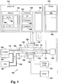
- Fig. 1 shows an analysis system 100 for detecting an analyte in a liquid sample.
- the analysis system is also designated as the 'measurement apparatus'.
- the analysis system 100 comprises an incubator 102 for receiving a liquid 104 that is a mixture of an aliquot of the liquid sample and a marker for marking the analyte, such as of a luminescence immunoassay.
- the analysis system 100 comprises a reservoir 106 that contains the co-reactant of the electrochemical reaction causing the luminescence.
- the incubator 102 and the reservoir 106 are coupled to a measuring cell 108 of the analysis system by a pipe system 110 through which a portion of the liquid 104 and the co-reactant can flow into the measuring cell 108.
- the measuring cell 108 comprises a cell body 112 that has a conduit 114 for receiving a portion of the liquid 104 and of the co-reactant through the pipe system 110.
- the measuring cell 108 has a magnetic component 116, such as a permanent magnet, for providing a magnetic field in the measuring cell.
- the magnetic component 116 may be coupled to an actuator 118 for rotating the magnetic component 116 to and from the conduit 114 in order to switch on or off the magnetic field within the conduit.
- the magnetic component 116 is positioned below a working electrode 120 that is coupled to a voltage source 122.
- An excitation area 124 is formed in the conduit 114 within the magnetic field caused by the magnetic component 116 on the working electrode 120.
- Luminescence that is caused in the excitation area 124 by the application of excitation energy i.e. the application of a voltaic trigger pulse on the working electrode 120
- an optical sensor such as a photomultiplier 126.
- the optical sensor is sensitive within a certain frequency range such that it provides a measurement signal to which an interfering signal may contribute, such as a luminescence signal caused by autoluminescent molecules that may be present in the measuring cell, provided that the luminescence is within the sensor's frequency range.
- the photomultiplier 126 is positioned opposite to the excitation area 124 over a window formed by counter electrodes 128 of the working electrode 120 through which the luminescence photons and any interfering photons caused by the excitation energy impinge on the photomultiplier 126.
- a resultant time resolved measurement signal 130 is provided from the photomultiplier 126 to a control unit 132 of the analysis system 100.
- the liquid contained within the conduit 114 is removed into a liquid waste container 134 and the measuring cell 108 is regenerated for a subsequent acquisition of a measurement signal.
- the control unit 132 is coupled to the voltage source 122 in order to control the voltage source 122 to apply the trigger signal to the working electrode 120.
- the control unit 132 is also coupled to the actuator 118 for controlling the actuator 118 to switch on and off the magnetic field by moving the permanent magnet correspondingly.
- control unit 132 may be coupled to a 'sipper unit', i.e. a pump 136, for extracting a portion of the liquid 104 from the incubator 102 and a portion of the co-reactant from the reservoir 106 as well as for removing the liquid from the measuring cell 108 and regeneration of the measuring cell.
- control unit 132 may be coupled to additional robotic components such as a pipetting station.
- the measuring cell 108 may be adapted for performing ECL-BBA using various luminescence immunoassays.
- ECL-BBA is discussed in the following, this is only an example and this example may be extended by the skilled person to other ECL techniques.
- the liquid 104 may contain a mixture of an aliquot of the liquid sample, streptavidin coated magnetic particles, biotinylated antibodies and ruthenylated antibodies to form a so-called 'sandwich' whereas the co-reactant contained in the reservoir 106 is tripropylamine (TPA).
- TPA tripropylamine
- magnetic particles 138 with a bound label flow into the conduit 114.
- the magnetic particles 138 are immobilized on the working electrode 120 when the magnetic field is switched on.
- the trigger pulse is applied on the working electrode 120 to cause the electrochemiluminescence in accordance with the ECL-BBA technique.
- the control unit 132 has an electronic memory 140 for storing reference data that describes the luminescence decay of a valid measurement signal without a superimposed interfering signal. That reference data is specific for the luminescence immunoassay that is utilized for the detection of the analyte.
- the reference data is stored in a lookup table or database table.
- the reference data comprises a reference dataset for each luminescence immunoassay supported by the analysis system 100. For example, for each supported immunoassay two coefficients a and b as well as a time t is stored in the memory.
- the coefficients a and b describe a linear law relating the maximum amplitude of the luminescence signal to a luminescence level reached after the decay time t. Storing the decay time t as part of the reference data may be superfluous if the considered decay time t is always the same.
- the control unit 132 has at least one electronic processor 144 for execution of program modules 146, 148 and 162.
- Program module 146 is executed by the processor 144 for acquisition of the measurement signal 132 whereas the program module 148 is executed by the processor 144 for evaluation of the acquired measurement signal 132.
- Program module 162 is executed by the processor 144 for acquisition of EIS data.
- the control unit 132 has an interface 150 for coupling a display unit (or display) 152 or another human-machine-interface to the control unit 132.
- the interface 150 may be implemented as a graphical user interface for displaying a window 154 for a user's selection of one of the luminescence immunoassays supported by the analysis system 100 as well as a window 156 for displaying a result of the analysis.
- the result of the analysis performed by the analysis system 100 may be output as tabular data with one column indicating the analyte to be detected and another column indicating the concentration of the analyte that has been detected.
- a further column may serve to indicate whether the detected concentration may be erroneous such as by displaying a flag or other warning signal or symbol, such as a red question- or exclamation mark.
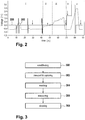
- FIG. 2 is a timing diagram showing the different phases of ECL-BBA and figure 3 is a respective flow chart.
- phase i is a conditioning phase in which a DC potential is applied with certain voltage pulses.
- the solid line 200 in figure 2 is the potential profile applied at the Working electrode (WE, 120) with respect to the Reference electrode (RE, 128).
- the conditioning has the purpose of preparing the working electrode for the subsequent measurements - conditioning is used to insure that the electrode has a known surface state at the start of the subsequent measurements.
- a user selects one of the luminescence immunoassays supported by the analysis system 100 by entering a respective selection into the window 154.
- the analysis of the liquid sample is started by execution of the program module 146 such that the pump 136 is controlled to transport a portion of the liquid 104 and of the co-reactant into the conduit 114.
- Line 202 in figure 2 designates the movement of any liquid transported via the pump 136 into and out of the measuring cell 108.
- the dashed line 202 is the movement of the dilutor piston of the pump 136 that moves the liquid through the cell.
- the actuator 118 is controlled to flip the permanent magnet into a position such that its magnetic field is applied to the conduit 114 for immobilization, i.e. capturing of the magnetic particles with their bound labels on the working electrode 120.
- the process of transport of the liquid and capturing of the magnetic particles is designated with block 302 and corresponds to phase ii in figure 2 .
- the voltage source 122 is controlled to apply the trigger pulse onto the working electrode for excitation of the luminescence such that the measurement signal 130 results.
- the measurement signal 130 is acquired by sampling the output of the photomultiplier 126 over a given period of time, such as 2 seconds after application of the trigger pulse by the voltage source 122, for time-resolved measuring of the luminescence.
- the data samples that constitute the measurement signal 130 are stored within the memory 140 of the control unit 132 and the program module 148 is started for evaluation of the acquired measurement signal 130. By execution of the program module 148 the amplitude of the measurement signal 130 is determined. Next, program module 148 performs a read access to the reference data 142 by reading the coefficients a and b of the user-selected immunoassay as well as the time t.
- the expected signal level reached by the measurement signal 130 after time t is calculated and compared to the actual signal level of the measurement signal 130 after that time t.
- a mismatch i.e. if the actual signal level of the measurement signal 130 is a predefined margin below or above the expected signal level, a mismatch and thus the presence of a superimposed interfering signal is detected.
- the concentration of the analyte, if any, in the liquid is determined by the program module 148 by means of the measurement signal 130 and the determined concentration is flagged by an error signal if the mismatch has been detected.
- phase v the pump 136 is controlled by the control unit 132 for removing the liquid from the conduit 114 and regeneration of the measuring cell 108.
- An optional washing step (block 304 and phase iii) in between the capturing (block 302) and measuring (block 306) may be performed in order to ensure that the marking substance bound to magnetic microparticles which are not yet attached to the magnet are removed prior to performing the ECL measurement in block 306.
- the measurement apparatus 100 is further adapted for performing electrochemical impedance spectroscopy, EIS.
- EIS electrochemical impedance spectroscopy
- the EIS is performed using the voltage source 122 and the counter electrode 120.
- the electronic processor 144 is thus further adapted for execution of the program module 162 for acquisition of EIS signals.
- the voltage source 122 is controlled to overlay an AC current signal onto the DC signal that is used to perform the ECL measurement as described above.
- EIS spectra can be acquired at given points of the measurement cycle discussed above and depicted in figure 2 .
- the measurement cycle is first carried out in a calibration process using a liquid sample void of the analyte.
- a first EIS is performed at a given point of the measurement cycle using the working electrode. Examples of said given point are depicted in figure 2 by arrows.
- the first EIS is then stored in the memory 140 as first EIS data 160.
- a further second EIS is performed at said given point. This results in second EIS data 164 that is stored in the memory. Then, the result of the first EIS and the second EIS are compared and an indication of a measurement state is provided indicating if the comparison results that a deviation between the first EIS and the second EIS is exceeding a predefined threshold.
- the measurement state is provided as a graphical output on the display 152.
- the control unit 132 may further be adapted to automatically accordingly select a countermeasure to correct for a failure of the analysis system 100. After initiation of the countermeasure, the measurement cycle is repeated in the analysis process and another second EIS is performed at the given point to check, if the countermeasure was successful and if the ECL measurement result is reliable or not.
- FIG 4 shows two different electrode configurations used for performing the ECL measurement.
- the working electrode (WE 120) is the designation for the electrode at which the electrochemical and ECL reactions of interest take place.
- the Counter or Auxiliary electrode (CE 128) is the electrode in the cell that completes the current path. Both electrodes are commonly made by an inert conductive material such as gold, platinum, glassy-carbon, iridium, boron doped diamond or any other materials which are effective for this purpose.
- any electrochemical cell must have at least a WE-CE pair for operation.
- This minimal 2 electrode configuration the terminals of the WE and CE are connected to the potential control unit.
- the 4-wire sensing method is used.
- separate pairs of current-carrying and voltage-sensing electrodes are used as shown in the figure 4a : S1 and S2 are used for the control and measurement of the WE and CE potential respectively.
- P1 and P2 are used for the control and measurement of current flowing through the respective electrodes. Separation of current and voltage electrodes eliminates the lead and contact resistance from the measurement, thus, allowing higher accuracy.
- RE reference electrode
- FIG 4b the RE provides a reference potential to which the applied voltage V 0 of the working electrode is referred.
- V 0 of the working electrode In the three electrode configuration a very low or ideally, no current is flowing through the RE.
- the RE keeps a stable potential.
- Typical REs are the silver/silver chloride, saturated calomel, mercury/mercury (mercurous) oxide, mercury/mercury sulfate or copper/copper sulfate electrode.
- a pseudo-reference electrode made of platinum, gold, stainless steel or other material can be used. These may however provide a less stable reference potential.
- the 4-wire sensing method is used for the EIS measurement.
- the 4-wire sensing method compensates the iR drop at the working electrode and at the counter electrode by 2 additional electrodes (4 wire configuration with sense wire 1 and sense wire 2 in Figure 4 c) for the EIS measurement (iR compensation).
- Very low AC responses applying very low sine amplitudes around 10 mVpp as cell voltage U cell are expected in 4-wire sensing method.
- a resistance R cable within a measuring cable can decrease the cell voltage significantly.
- the applied sine wave potential is equal to the cell potential, because any potential drops are eliminated by the sense wires.
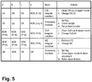
- Figure 5 shows a decision table that provides countermeasures based on combinations of measurement states.
- the flowchart in figure 6 illustrates a method that leads to the decisions of figure 5 .
- the flowchart of figure 6 and the decision table of figure 5 are based on the assumption, that for at least two of the above mentioned phases i.-v. an EIS measurement was performed.
- a first EIS was performed in a calibration process when carrying out the measurement cycle.
- the calibration process assumes in general that the result of the respective first EIS is representative of a system that is behaving as desired.
- a second EIS is performed at the same given point.
- the first (calibration) EIS and the second (real sample) EIS are then compared and a measurement state is determined which indicates if the comparison results that a deviation between the first EIS and the second EIS is exceeding a predefined threshold.
- the measurement states resulting from more than one given point and thus more than two second EIS are then used to determine the reliability of the ECL measurement performed during the measurement cycle of the analysis process.
- the assay run indication is identical with the measurement state obtained as described above in an EIS measurement using a real liquid sample.
- a prepare run indication is identical with the measurement state obtained as described above in an EIS measurement, however with a liquid sample that is void of any analyte.
- a third EIS is performed while carrying out the measurement cycle using a liquid sample void of any analyte. Then, this third EIS is compared with the first EIS obtained for the same given point and a measurement state is determined which indicates if the comparison results that a deviation between the first EIS and the third EIS is exceeding a predefined threshold.
- the prepare run indication may define the prepare run indication as positive in case the comparison results that a deviation between the compared first and third EIS is within the predefined threshold and as negative in case the comparison results that a deviation between compared first and third EIS is outside the predefined threshold.
- the variable 'Y' of the flowchart of figure 6 is thereby the measurement state.
- the index a, b, and d are representative of given points indicated by the arrows in figure 2 for phase i, ii, v, respectively.
- Index c is representative of either the given point indicated by the arrow in phase iii. of figure 2 , or by the arrow in phase iv.
- the method starts in block 500 with the acquisition of EIS. It has to be noted, that in figures 5 and 6 the acquisition of second EIS in four phases and the acquisition of a third EIS in phase v. is used. However, it is also possible to reduce the number of used second and third EIS which however may have the disadvantage that problematic or error prone ECL measurements may not be accurately assignable to a certain reason.
- the assay run indication for point 1 is negative, this may be attributed to different reasons.
- One reason may be an aging of the measuring cell or a contamination of the measuring cell or the involved system reagents or components such as co-reactant solution, cleaning solution and the measuring cell. Aging of the measuring cell continuously degrades the performance of the ECL assay while contamination typically results in a spontaneous change of the ECL assay behavior.
- the method continues with block 522 and the determination, how for the same given point the present second EIS deviates from second EIS obtained from a previous measurement.
- the second EIS at the given point is compared with a respective second EIS obtained for the same given point in an n to last subsequent run of the electrochemiluminescence measurement cycle, n being a variable in between 1 and 1000.
- n being a variable in between 1 and 1000.
- the deviation ⁇ ya of the present EIS from the previous EIS is exceeding a predefined aging threshold 'x', this may be attributed to a contamination of the system. This may be understood as a 'sudden jump' of the EIS curve obtained for the present measurement run compared to a previous measurement run.
- the deviation ⁇ ya is below the aging threshold, this may be attributed to a continuous aging of the measuring cell.
- it may be determined in block 530 if the absolute value ya of the difference between the first and the second EIS for said point is exceeding an absolute aging value abs. If this is the case, in block 530 information may be provided by the system for example using the display 152 that the measuring cell has to be exchanged due to aging reasons. More simplified, a message 'call service' may be output.
- Block 524 is chosen in case said deviation occurred for the first time
- block 526 is chosen in case said deviation occurred for the second time
- block 528 is chosen in case said deviation occurred for the third time. For this reason, the presence of a flag is checked: in case no flag is associated with the second EIS for the given point (or the flag is 1), block 524 will be chosen. In case the flag is set (or the flag is 2), block 526 will be chosen etc.
- blocks 524, 526 and 528 correspond to the preferably automated initiation of countermeasures.
- the flag is set (or increased from 1 to 2) and a message may be output via the display that the cup containing the co-reactant solution and the sipper nozzle used to obtain the co-reactant solution from its reservoir has to be cleaned.
- the message may recommend to change the present co-reactant solution lot.
- said cleaning and said changing may be automatically initiated and performed by the system.
- Block 524 corresponds to the third line in the decision table of figure 5 . After completion of block 524, the method restarts with block 500.
- a message may be output via the display that a liquid flow cleaning (LFC) of the system has to be performed.
- Liquid flow cleaning occurs when this function is initiated from the service screen of the instrument.
- LFC a sodium hypochlorite solution is aspirated for cleaning of the measuring cells and the flow path.
- said LFC may be automatically initiated and performed by the system.
- a preferably automated exchange of the measuring cell (MC) may be initiated.
- Block 524 corresponds to the fourth line in the decision table of figure 5 . After completion of block 524, the method restarts with block 500.
- the flag may be realized by any known method which allows distinguishing between the first, second or third time that ⁇ ya>x is occurring in a successive manner.
- information may be provided by the system has an undefined malfunction. More simplified, a message 'call service' may be output. Here, the system will stop and the method will end.
- Yb is the result of the EIS obtained during or at the end of the provision of the liquid sample to the measuring cell and capturing of magnetic microparticles.
- Yb may be obtained at the given point indicated by the arrow in phase ii. or phase iv.
- the assay run indication is negative, the method distinguished between the first time and the second time this problem is occurring. For this purpose, the assay run indication again uses a respective flag as it was discussed with respect to Ya.
- Block 518 this may be attributed to a problem with the analyte.
- the analyte may comprise air bubbles or it may be contaminated.
- a message may be output via the display that the sample quality has to be checked. Further the flag is set (or increased in number).
- the system may automatically obtain a new liquid sample with the same analyte.
- Block 518 corresponds to the last line in the decision table of figure 5 . After completion of block 518, the method restarts with block 500.
- block 504 is immediately followed by block 512 which corresponds to block 528.
- block 506 it is determined if the assay run indication for Yc (obtained at the given point indicated with the arrow in phase iii.) is positive or not.
- Yc is the result of the EIS obtained during the phase for washing of the measuring cell after the capturing and before the electrochemiluminescence measurement. In case Yc is negative, this immediately may result in execution of block 512.
- the decision with respect to Yc is not reflected in the decision table of figure 5 since the cleaning step in phase iii. is optional.
- Yc is positive or directly after block 504 (Yb ok)
- the method continues with block 508 and the determination, if the assay run indication for Yd is positive or not.
- Yd is the result of the EIS obtained during phase v., i.e. during cleaning of the measuring cell with the working electrode with a cleaning solution.
- the method ends with block 520 and the determination that the ECL measurement is reliable.
- block 510 following block 508 determines if the present Yd is the result of an assay run or a prepare run of the measurement cycle. In case it is the result of a measurement run, a message is output according to which the sample quality is to be checked. The system may automatically continue with subsequent block 500 in prepare run, i.e. in a run of the measuring cycle with a liquid sample void of any analyte.
- the method continues either with block 514 in case the prepare run is performed for the first time, or with block 512 in case the prepare run is performed for the second time.
- First and second time may be checked by means of a flag correspondingly as described above.
- Block 514 corresponding to the first line in the decision table of figure 5 may output a message according to which the cleaning solution cup, a reservoir on the instrument in which the cleaning solution is dispensed, and the nozzle used to transport the cleaning solution into the measuring cell is to be cleaned and to exchange the currently used cleaning solution lot with a new one. Alternatively or additionally the cleaning and exchanging may be performed automatically. After block 514 the method continues with block 500.
- FIG. 7 shows EIS measurement results on admittance and phase for illustrating the effect of a contaminated cleaning solution and a clean cleaning solution.
- SAP Streptavidin particles
- the EIS measurements were performed at the points indicated in figure 2 for phase i, iv and v.
- phase i is designated as 'Con I'
- phase iv is designated as 'Con II & C'
- phase v is designated as 'Clean'.
- (+) means that the cleaning solution was clean whereas (-) means that the cleaning solution was contaminated.
- the EIS measurements were performed at 0 Hz, 100 Hz, 300 Hz and 1000 Hz.
- phase v a strong deviation (>> 1SD) between the EIS obtained as calibration data (straight lines) and the EIS obtained for the measurement on the contaminated cleaning solution (dashed lines) is already visible in admittance at 100 Hz. Further, the standard deviation obtained for the measurement points in phase v is far below the deviation between the calibration curve and the measurement curve obtained for the contaminated cleaning solution. This shows that an improper cleaning solution can be easily detected and identified as such.
- FIG 8 shows EIS measurement results on admittance and phase for illustrating the effect of a contaminated co-reactant solution and a clean co-reactant solution.
- SAP Streptavidin particles
- (+) means that the co-reactant solution was clean whereas (-) means that the co-reactant solution was contaminated.
- the EIS measurements were performed at 0 Hz, 100 Hz, 300 Hz and 1000 Hz.
- the dashed lines correspond to the calibration data, the straight lines to the measurement data on the contaminated co-reactant solution.
- FIG. 9 shows EIS measurement results on admittance for illustrating the effect of a pipetting error of the sample to be analyzed. Due to the pipetting error, air is pipetted and transferred into the measuring cell. In phase ii, this results in a significant deviation between the admittance obtained for the EIS calibration (IncTrans) and the EIS obtained on sample with the pipetting error (IncTrans air). The result is a 700% change in admittance and a 60% change in phase due to the presence of air. Thus a malfunctioning pipetting or incubate sipping can be detected.
- Measurements were carried out using an artificial immunoassay (SAP) - an assay including RuBpy labeled microparticles for a high specific ECL signal.
- SAP artificial immunoassay
- the protocols for the assays mentioned below were taken as recommend for Roche Elecsys® 2010 with slight adaptations in the volumes.
- the volume of bead suspension was 35 ⁇ l
- the volume of free RuBpy conjugate was 15 ⁇ l
- the volume of bead buffer was 150 ⁇ l
- the volume of sample was 0 ⁇ l.
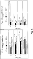
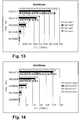
- Figures 10 and 11 shows EIS measuring results that are proving that it is possible to identify erroneous system reagents/components such as co-reactant solution, cleaning solution and the measuring cell. This requires high reproducibility of the EIS results for measurements of the untainted system. In order to do so the analyzer was equipped with an intact measuring cell and flawless lots of cleaning solution and co-reactant solution.
- CoS co-reactant solution
- phase shows a clear discrimination between old and new measuring cells.
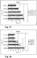
- the changes are most significant for frequencies ⁇ 1000Hz for phase i and phase v and 10kHz for phase iv, compare figures 16 , 17 and 180. It has to be noted that the change by cell aging is gradual and can therefore be distinguished from non-aging related processes that cause changes on short timescales.
- EIS can be used to monitor the sample pipetting. If no sample is pipetted the incubate it is free of serum components and no adsorption is expected at the electrode. Such an event can be easily spotted by the EIS method as an "anomalous incubate" and a warning can be sent to the operator and/or respective countermeasures can be automatically initiated.
- High troughput analyzers such e170, e601, e602 and e801 on the other hand make use of a so called PreWash function.
- the magnetic beads are magnetically captured at the vessel wall.
- the incubate containing assay reagents and serum is removed and substituted by buffer solution.
- This "prewashed incubate” is free of serum components.
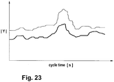
- Figure 23 is an EIS spectrum that is expected as a result of a continuous measurement over the whole measuring cycle of figure 2 at single frequency of 1000 Hz.
- the measurement result of the admittance of such a continuous EIS is shown in figure 26.
- the lower line corresponds to a measuring cycle in which a flawless co-reactant solution was used, whereas the upper line corresponds to a measuring cycle in which co-reactant solution in an irregular condition was used.
- An overall admittance shift to higher values can be easily observed in that case.
- aspects of the present invention may be embodied as an apparatus, method or computer program product. Accordingly, aspects of the present invention may take the form of an entirely hardware embodiment, an entirely software embodiment (including firmware, resident software, micro-code, etc.) or an embodiment combining software and hardware aspects that may all generally be referred to herein as a "circuit,” “module” or “system.” Furthermore, aspects of the present invention may take the form of a computer program product embodied in one or more computer readable medium(s) having computer executable code embodied thereon.
- the computer readable medium may be a computer readable signal medium or a computer readable storage medium.
- a 'computer-readable storage medium' as used herein encompasses any tangible storage medium which may store instructions which are executable by a processor of a computing device.
- the computer-readable storage medium may be referred to as a computer-readable non-transitory storage medium.
- the computer-readable storage medium may also be referred to as a tangible computer readable medium.
- a computer-readable storage medium may also be able to store data which is able to be accessed by the processor of the computing device.
- Examples of computer-readable storage media include, but are not limited to: a floppy disk, a magnetic hard disk drive, a solid state hard disk, flash memory, a USB thumb drive, Random Access Memory (RAM), Read Only Memory (ROM), an optical disk, a magneto-optical disk, and the register file of the processor.
- optical disks include Compact Disks (CD) and Digital Versatile Disks (DVD), for example CD-ROM, CD-RW, CD-R, DVD-ROM, DVD-RW, or DVD-R disks.
- computer readable-storage medium also refers to various types of recording media capable of being accessed by the computer device via a network or communication link. For example a data may be retrieved over a modem, over the internet, or over a local area network.
- Computer executable code embodied on a computer readable medium may be transmitted using any appropriate medium, including but not limited to wireless, wireline, optical fiber cable, RF, etc., or any suitable combination of the foregoing.
- a computer readable signal medium may include a propagated data signal with computer executable code embodied therein, for example, in baseband or as part of a carrier wave. Such a propagated signal may take any of a variety of forms, including, but not limited to, electro-magnetic, optical, or any suitable combination thereof.
- a computer readable signal medium may be any computer readable medium that is not a computer readable storage medium and that can communicate, propagate, or transport a program for use by or in connection with an instruction execution system, apparatus, or device.
- 'Computer memory' or 'memory' is an example of a computer-readable storage medium.
- Computer memory is any memory which is directly accessible to a processor.
- 'Computer storage' or 'storage' is a further example of a computer-readable storage medium.
- Computer storage is any non-volatile computer-readable storage medium. In some embodiments computer storage may also be computer memory or vice versa.
- a 'processor' as used herein encompasses an electronic component which is able to execute a program or machine executable instruction or computer executable code.
- References to the computing device comprising "a processor” should be interpreted as possibly containing more than one processor or processing core.
- the processor may for instance be a multi-core processor.
- a processor may also refer to a collection of processors within a single computer system or distributed amongst multiple computer systems.
- the term computing device should also be interpreted to possibly refer to a collection or network of computing devices each comprising a processor or processors.
- the computer executable code may be executed by multiple processors that may be within the same computing device or which may even be distributed across multiple computing devices.
- Computer executable code may comprise machine executable instructions or a program which causes a processor to perform an aspect of the present invention.
- Computer executable code for carrying out operations for aspects of the present invention may be written in any combination of one or more programming languages, including an object oriented programming language such as Java, Smalltalk, C++ or the like and conventional procedural programming languages, such as the "C" programming language or similar programming languages and compiled into machine executable instructions.
- the computer executable code may be in the form of a high level language or in a pre-compiled form and be used in conjunction with an interpreter which generates the machine executable instructions on the fly.
- the computer executable code may execute entirely on the user's computer, partly on the user's computer, as a stand-alone software package, partly on the user's computer and partly on a remote computer or entirely on the remote computer or server.
- the remote computer may be connected to the user's computer through any type of network, including a local area network (LAN) or a wide area network (WAN), or the connection may be made to an external computer (for example, through the Internet using an Internet Service Provider).
- These computer program instructions may be provided to a processor of a general purpose computer, special purpose computer, or other programmable data processing apparatus to produce a machine, such that the instructions, which execute via the processor of the computer or other programmable data processing apparatus, create means for implementing the functions/acts specified in the flowchart and/or block diagram block or blocks.
- These computer program instructions may also be stored in a computer readable medium that can direct a computer, other programmable data processing apparatus, or other devices to function in a particular manner, such that the instructions stored in the computer readable medium produce an article of manufacture including instructions which implement the function/act specified in the flowchart and/or block diagram block or blocks.
- the computer program instructions may also be loaded onto a computer, other programmable data processing apparatus, or other devices to cause a series of operational steps to be performed on the computer, other programmable apparatus or other devices to produce a computer implemented process such that the instructions which execute on the computer or other programmable apparatus provide processes for implementing the functions/acts specified in the flowchart and/or block diagram block or blocks.
Landscapes
- Health & Medical Sciences (AREA)
- Life Sciences & Earth Sciences (AREA)
- Chemical & Material Sciences (AREA)
- Immunology (AREA)
- Engineering & Computer Science (AREA)
- Physics & Mathematics (AREA)
- General Health & Medical Sciences (AREA)
- Analytical Chemistry (AREA)
- Biochemistry (AREA)
- Molecular Biology (AREA)
- Pathology (AREA)
- General Physics & Mathematics (AREA)
- Urology & Nephrology (AREA)
- Hematology (AREA)
- Biomedical Technology (AREA)
- Biotechnology (AREA)
- Microbiology (AREA)
- Organic Chemistry (AREA)
- Zoology (AREA)
- Food Science & Technology (AREA)
- Medicinal Chemistry (AREA)
- Wood Science & Technology (AREA)
- Cell Biology (AREA)
- Proteomics, Peptides & Aminoacids (AREA)
- Chemical Kinetics & Catalysis (AREA)
- Quality & Reliability (AREA)
- Electrochemistry (AREA)
- Nuclear Medicine, Radiotherapy & Molecular Imaging (AREA)
- Genetics & Genomics (AREA)
- Bioinformatics & Cheminformatics (AREA)
- Biophysics (AREA)
- General Engineering & Computer Science (AREA)
- Spectroscopy & Molecular Physics (AREA)
- Plasma & Fusion (AREA)
- Investigating Or Analysing Materials By The Use Of Chemical Reactions (AREA)
- Investigating Or Analyzing Materials By The Use Of Electric Means (AREA)
- Investigating, Analyzing Materials By Fluorescence Or Luminescence (AREA)
Applications Claiming Priority (3)
| Application Number | Priority Date | Filing Date | Title |
|---|---|---|---|
| EP16153257 | 2016-01-29 | ||
| EP16158014 | 2016-03-01 | ||
| PCT/EP2017/051868 WO2017129803A1 (en) | 2016-01-29 | 2017-01-27 | Electrochemiluminescence method and apparatus for detecting an analyte in a liquid sample |
Publications (2)
| Publication Number | Publication Date |
|---|---|
| EP3408401A1 EP3408401A1 (en) | 2018-12-05 |
| EP3408401B1 true EP3408401B1 (en) | 2019-11-20 |
Family
ID=57914974
Family Applications (1)
| Application Number | Title | Priority Date | Filing Date |
|---|---|---|---|
| EP17702082.3A Active EP3408401B1 (en) | 2016-01-29 | 2017-01-27 | Electrochemiluminescence method and apparatus for detecting an analyte in a liquid sample |
Country Status (8)
| Country | Link |
|---|---|
| US (1) | US11796477B2 (ja) |
| EP (1) | EP3408401B1 (ja) |
| JP (1) | JP7041623B2 (ja) |
| KR (1) | KR20180105127A (ja) |
| CN (1) | CN108431231B (ja) |
| BR (1) | BR112018010902A2 (ja) |
| ES (1) | ES2770223T3 (ja) |
| WO (1) | WO2017129803A1 (ja) |
Families Citing this family (9)
| Publication number | Priority date | Publication date | Assignee | Title |
|---|---|---|---|---|
| TWI703322B (zh) * | 2018-10-04 | 2020-09-01 | 台灣奈米碳素股份有限公司 | 生化檢驗方法及裝置 |
| US11977050B2 (en) * | 2018-12-27 | 2024-05-07 | Hitachi High-Tech Corporation | Automated analyzer, automatic analysis system, and automatic sample analysis method |
| US20220283094A1 (en) * | 2019-07-31 | 2022-09-08 | Hitachi High-Tech Corporation | Biomolecular analysis method and biomolecular analyzer |
| CN111198181A (zh) * | 2020-01-10 | 2020-05-26 | 苏州易莱生物技术有限公司 | 用于电化学发光检测的方法和装置 |
| US11771368B2 (en) | 2020-03-09 | 2023-10-03 | Arizona Board Of Regents On Behalf Of Arizona State University | Rapid assessment of microcirculation in patients to realize closed-loop systems |
| US11953532B2 (en) * | 2020-03-09 | 2024-04-09 | Arizona Board Of Regents On Behalf Of Arizona State University | Systems and methods to determine electrochemical impedance spectrogram rapidly in real time |
| KR102448945B1 (ko) * | 2021-01-08 | 2022-09-30 | 주식회사 위즈맥 | Eis 측정 및 알고리즘 방식을 통한 전기화학 전극센서 트랜스듀서의 자동 교정 방법, 수명 진단 방법, 및 양불 진단 방법 |
| CN114371161B (zh) * | 2021-11-15 | 2023-09-22 | 吉林大学 | 一种基于具有偏振分辨特性的表面增敏电化学发光分析方法及应用 |
| JP7455249B1 (ja) | 2023-02-27 | 2024-03-25 | 住友化学株式会社 | 電気化学的測定方法、電気化学的測定装置、及びプログラム |
Family Cites Families (20)
| Publication number | Priority date | Publication date | Assignee | Title |
|---|---|---|---|---|
| US5238808A (en) * | 1984-10-31 | 1993-08-24 | Igen, Inc. | Luminescent metal chelate labels and means for detection |
| US5068088A (en) | 1988-11-03 | 1991-11-26 | Igen, Inc. | Method and apparatus for conducting electrochemiluminescent measurements |
| US5667651A (en) * | 1995-07-13 | 1997-09-16 | Bryan; Avron | Apparatus and associated method for reducing an undesired constituent of gas associated with wastewater and having sensor fault detection |
| DE19803528A1 (de) * | 1998-01-30 | 1999-08-05 | Roche Diagnostics Gmbh | Verfahren zur Analyse einer Probe mittels eines Elektrochemolumineszenz-Bindungsreaktion-Tests |
| WO2004011931A1 (en) | 2002-07-26 | 2004-02-05 | Instrumentation Laboratory Company | Compositions and method for reducing the rate of oxygen loss from aqueous |
| CA2623782C (en) | 2001-08-22 | 2015-04-07 | Instrumentation Laboratory Company | An automated system for continuously and automatically calibrating electrochemical sensors |
| CA3171720C (en) | 2002-12-26 | 2024-01-09 | Meso Scale Technologies, Llc. | Methods for conducting electrochemiluminescence measurements |
| US7488601B2 (en) | 2003-06-20 | 2009-02-10 | Roche Diagnostic Operations, Inc. | System and method for determining an abused sensor during analyte measurement |
| US8088204B2 (en) | 2005-03-01 | 2012-01-03 | Taylor S Ray | Synergistic combinations of chromate-free corrosion inhibitors |
| US8088596B2 (en) * | 2006-10-10 | 2012-01-03 | Oakland University | Method of microorganism detection using carbohydrate and lectin recognition |
| GB0700640D0 (en) | 2007-01-12 | 2007-02-21 | Iti Scotland Ltd | Detecting analytes |
| JPWO2009054474A1 (ja) | 2007-10-26 | 2011-03-10 | 凸版印刷株式会社 | アレル判定装置及び方法、ならびに、コンピュータプログラム |
| WO2010014622A2 (en) | 2008-07-28 | 2010-02-04 | Fondazione Istituto Firc Di Oncologica Molecolare (Ifom) | In vitro model for modulating the blood brain barrier and methods of screening |
| US8000936B2 (en) * | 2008-11-10 | 2011-08-16 | Saudi Arabian Oil Company | Data analysis system for determining coating conditions of a buried pipeline |
| DE102011005966A1 (de) | 2011-03-23 | 2012-09-27 | Robert Bosch Gmbh | Verfahren und Vorrichtung zum Betrieb eines elektrochemischen Energiewandlers |
| CN103076572A (zh) * | 2012-12-27 | 2013-05-01 | 天津力神电池股份有限公司 | 一种根据eis谱快速判断负极涂布工艺对电池循环性能影响的方法 |
| EP2816345A1 (en) * | 2013-06-19 | 2014-12-24 | Roche Diagniostics GmbH | Electrochemiluminescence method of detecting an analyte in a liquid sample and analysis system |
| CN103604921B (zh) * | 2013-11-05 | 2015-08-12 | 浙江大学 | 一种化学发光免疫生物传感器检测装置及检测分析方法 |
| US9943256B2 (en) | 2013-12-16 | 2018-04-17 | Medtronic Minimed, Inc. | Methods and systems for improving the reliability of orthogonally redundant sensors |
| CN103940808B (zh) | 2014-04-30 | 2015-12-02 | 青岛大学 | 一种双信号放大电化学发光生物传感器的制备方法及应用 |
-
2017
- 2017-01-27 BR BR112018010902A patent/BR112018010902A2/pt not_active Application Discontinuation
- 2017-01-27 KR KR1020187018048A patent/KR20180105127A/ko not_active Application Discontinuation
- 2017-01-27 WO PCT/EP2017/051868 patent/WO2017129803A1/en unknown
- 2017-01-27 ES ES17702082T patent/ES2770223T3/es active Active
- 2017-01-27 JP JP2018532316A patent/JP7041623B2/ja active Active
- 2017-01-27 CN CN201780005232.8A patent/CN108431231B/zh active Active
- 2017-01-27 EP EP17702082.3A patent/EP3408401B1/en active Active
-
2018
- 2018-07-25 US US16/044,897 patent/US11796477B2/en active Active
Non-Patent Citations (1)
| Title |
|---|
| None * |
Also Published As
| Publication number | Publication date |
|---|---|
| CN108431231A (zh) | 2018-08-21 |
| US11796477B2 (en) | 2023-10-24 |
| BR112018010902A2 (pt) | 2018-11-21 |
| JP2019512665A (ja) | 2019-05-16 |
| JP7041623B2 (ja) | 2022-03-24 |
| ES2770223T3 (es) | 2020-07-01 |
| US20180348140A1 (en) | 2018-12-06 |
| KR20180105127A (ko) | 2018-09-27 |
| WO2017129803A1 (en) | 2017-08-03 |
| CN108431231B (zh) | 2021-09-10 |
| EP3408401A1 (en) | 2018-12-05 |
Similar Documents
| Publication | Publication Date | Title |
|---|---|---|
| US11796477B2 (en) | Reliability indicating method for an electrochemiluminescence method for detecting an analyte in a liquid sample | |
| US11726044B2 (en) | Method of monitoring an operation of detection of an analyte in a liquid sample | |
| RU2465812C2 (ru) | Система детектирования аномального выходного сигнала для биосенсора | |
| JP4573486B2 (ja) | ルミネセンス測定法 | |
| US11703504B2 (en) | Electrochemiluminescence method of detecting an analyte in a liquid sample and analysis system | |
| US6599473B1 (en) | Electrochemilumiscence method for detecting analytes | |
| EP0640832A2 (en) | Electrochemical immunosensor system | |
| JP5977654B2 (ja) | 液体試料中の分析物を検出する発光法及び分析システム | |
| Wongkittisuksa et al. | Development and application of a real-time capacitive sensor | |
| RU2564516C2 (ru) | Способ измерения емкости и его применение | |
| WO2008155539A1 (en) | Electrochemical data rejection methodology | |
| Sun et al. | Hybridization-induced Ag (I) dissociation from an immobilization-free and label-free hairpin DNA: toward a novel electronic monitoring platform | |
| CN103940865A (zh) | 一种β-内酰胺类抗生素残留快速检测仪 | |
| US20240053293A1 (en) | Device for analysing a biological fluid | |
| CN103913580A (zh) | 一种用于心梗诊断的纳米技术及其装置 |
Legal Events
| Date | Code | Title | Description |
|---|---|---|---|
| STAA | Information on the status of an ep patent application or granted ep patent |
Free format text: STATUS: UNKNOWN |
|
| STAA | Information on the status of an ep patent application or granted ep patent |
Free format text: STATUS: THE INTERNATIONAL PUBLICATION HAS BEEN MADE |
|
| PUAI | Public reference made under article 153(3) epc to a published international application that has entered the european phase |
Free format text: ORIGINAL CODE: 0009012 |
|
| STAA | Information on the status of an ep patent application or granted ep patent |
Free format text: STATUS: REQUEST FOR EXAMINATION WAS MADE |
|
| 17P | Request for examination filed |
Effective date: 20180829 |
|
| AK | Designated contracting states |
Kind code of ref document: A1 Designated state(s): AL AT BE BG CH CY CZ DE DK EE ES FI FR GB GR HR HU IE IS IT LI LT LU LV MC MK MT NL NO PL PT RO RS SE SI SK SM TR |
|
| AX | Request for extension of the european patent |
Extension state: BA ME |
|
| DAV | Request for validation of the european patent (deleted) | ||
| DAX | Request for extension of the european patent (deleted) | ||
| GRAP | Despatch of communication of intention to grant a patent |
Free format text: ORIGINAL CODE: EPIDOSNIGR1 |
|
| STAA | Information on the status of an ep patent application or granted ep patent |
Free format text: STATUS: GRANT OF PATENT IS INTENDED |
|
| INTG | Intention to grant announced |
Effective date: 20190611 |
|
| GRAS | Grant fee paid |
Free format text: ORIGINAL CODE: EPIDOSNIGR3 |
|
| GRAA | (expected) grant |
Free format text: ORIGINAL CODE: 0009210 |
|
| STAA | Information on the status of an ep patent application or granted ep patent |
Free format text: STATUS: THE PATENT HAS BEEN GRANTED |
|
| AK | Designated contracting states |
Kind code of ref document: B1 Designated state(s): AL AT BE BG CH CY CZ DE DK EE ES FI FR GB GR HR HU IE IS IT LI LT LU LV MC MK MT NL NO PL PT RO RS SE SI SK SM TR |
|
| REG | Reference to a national code |
Ref country code: GB Ref legal event code: FG4D |
|
| REG | Reference to a national code |
Ref country code: CH Ref legal event code: EP |
|
| REG | Reference to a national code |
Ref country code: DE Ref legal event code: R096 Ref document number: 602017008903 Country of ref document: DE |
|
| REG | Reference to a national code |
Ref country code: IE Ref legal event code: FG4D |
|
| REG | Reference to a national code |
Ref country code: AT Ref legal event code: REF Ref document number: 1204237 Country of ref document: AT Kind code of ref document: T Effective date: 20191215 |
|
| REG | Reference to a national code |
Ref country code: NL Ref legal event code: MP Effective date: 20191120 |
|
| REG | Reference to a national code |
Ref country code: LT Ref legal event code: MG4D |
|
| PG25 | Lapsed in a contracting state [announced via postgrant information from national office to epo] |
Ref country code: LT Free format text: LAPSE BECAUSE OF FAILURE TO SUBMIT A TRANSLATION OF THE DESCRIPTION OR TO PAY THE FEE WITHIN THE PRESCRIBED TIME-LIMIT Effective date: 20191120 Ref country code: NL Free format text: LAPSE BECAUSE OF FAILURE TO SUBMIT A TRANSLATION OF THE DESCRIPTION OR TO PAY THE FEE WITHIN THE PRESCRIBED TIME-LIMIT Effective date: 20191120 Ref country code: FI Free format text: LAPSE BECAUSE OF FAILURE TO SUBMIT A TRANSLATION OF THE DESCRIPTION OR TO PAY THE FEE WITHIN THE PRESCRIBED TIME-LIMIT Effective date: 20191120 Ref country code: BG Free format text: LAPSE BECAUSE OF FAILURE TO SUBMIT A TRANSLATION OF THE DESCRIPTION OR TO PAY THE FEE WITHIN THE PRESCRIBED TIME-LIMIT Effective date: 20200220 Ref country code: NO Free format text: LAPSE BECAUSE OF FAILURE TO SUBMIT A TRANSLATION OF THE DESCRIPTION OR TO PAY THE FEE WITHIN THE PRESCRIBED TIME-LIMIT Effective date: 20200220 Ref country code: GR Free format text: LAPSE BECAUSE OF FAILURE TO SUBMIT A TRANSLATION OF THE DESCRIPTION OR TO PAY THE FEE WITHIN THE PRESCRIBED TIME-LIMIT Effective date: 20200221 Ref country code: LV Free format text: LAPSE BECAUSE OF FAILURE TO SUBMIT A TRANSLATION OF THE DESCRIPTION OR TO PAY THE FEE WITHIN THE PRESCRIBED TIME-LIMIT Effective date: 20191120 Ref country code: SE Free format text: LAPSE BECAUSE OF FAILURE TO SUBMIT A TRANSLATION OF THE DESCRIPTION OR TO PAY THE FEE WITHIN THE PRESCRIBED TIME-LIMIT Effective date: 20191120 |
|
| PG25 | Lapsed in a contracting state [announced via postgrant information from national office to epo] |
Ref country code: HR Free format text: LAPSE BECAUSE OF FAILURE TO SUBMIT A TRANSLATION OF THE DESCRIPTION OR TO PAY THE FEE WITHIN THE PRESCRIBED TIME-LIMIT Effective date: 20191120 Ref country code: RS Free format text: LAPSE BECAUSE OF FAILURE TO SUBMIT A TRANSLATION OF THE DESCRIPTION OR TO PAY THE FEE WITHIN THE PRESCRIBED TIME-LIMIT Effective date: 20191120 Ref country code: IS Free format text: LAPSE BECAUSE OF FAILURE TO SUBMIT A TRANSLATION OF THE DESCRIPTION OR TO PAY THE FEE WITHIN THE PRESCRIBED TIME-LIMIT Effective date: 20200320 |
|
| PG25 | Lapsed in a contracting state [announced via postgrant information from national office to epo] |
Ref country code: AL Free format text: LAPSE BECAUSE OF FAILURE TO SUBMIT A TRANSLATION OF THE DESCRIPTION OR TO PAY THE FEE WITHIN THE PRESCRIBED TIME-LIMIT Effective date: 20191120 |
|
| REG | Reference to a national code |
Ref country code: ES Ref legal event code: FG2A Ref document number: 2770223 Country of ref document: ES Kind code of ref document: T3 Effective date: 20200701 |
|
| PG25 | Lapsed in a contracting state [announced via postgrant information from national office to epo] |
Ref country code: RO Free format text: LAPSE BECAUSE OF FAILURE TO SUBMIT A TRANSLATION OF THE DESCRIPTION OR TO PAY THE FEE WITHIN THE PRESCRIBED TIME-LIMIT Effective date: 20191120 Ref country code: CZ Free format text: LAPSE BECAUSE OF FAILURE TO SUBMIT A TRANSLATION OF THE DESCRIPTION OR TO PAY THE FEE WITHIN THE PRESCRIBED TIME-LIMIT Effective date: 20191120 Ref country code: DK Free format text: LAPSE BECAUSE OF FAILURE TO SUBMIT A TRANSLATION OF THE DESCRIPTION OR TO PAY THE FEE WITHIN THE PRESCRIBED TIME-LIMIT Effective date: 20191120 Ref country code: EE Free format text: LAPSE BECAUSE OF FAILURE TO SUBMIT A TRANSLATION OF THE DESCRIPTION OR TO PAY THE FEE WITHIN THE PRESCRIBED TIME-LIMIT Effective date: 20191120 Ref country code: PT Free format text: LAPSE BECAUSE OF FAILURE TO SUBMIT A TRANSLATION OF THE DESCRIPTION OR TO PAY THE FEE WITHIN THE PRESCRIBED TIME-LIMIT Effective date: 20200412 |
|
| REG | Reference to a national code |
Ref country code: AT Ref legal event code: MK05 Ref document number: 1204237 Country of ref document: AT Kind code of ref document: T Effective date: 20191120 |
|
| REG | Reference to a national code |
Ref country code: DE Ref legal event code: R097 Ref document number: 602017008903 Country of ref document: DE |
|
| PG25 | Lapsed in a contracting state [announced via postgrant information from national office to epo] |
Ref country code: SK Free format text: LAPSE BECAUSE OF FAILURE TO SUBMIT A TRANSLATION OF THE DESCRIPTION OR TO PAY THE FEE WITHIN THE PRESCRIBED TIME-LIMIT Effective date: 20191120 Ref country code: MC Free format text: LAPSE BECAUSE OF FAILURE TO SUBMIT A TRANSLATION OF THE DESCRIPTION OR TO PAY THE FEE WITHIN THE PRESCRIBED TIME-LIMIT Effective date: 20191120 Ref country code: SM Free format text: LAPSE BECAUSE OF FAILURE TO SUBMIT A TRANSLATION OF THE DESCRIPTION OR TO PAY THE FEE WITHIN THE PRESCRIBED TIME-LIMIT Effective date: 20191120 |
|
| PLBE | No opposition filed within time limit |
Free format text: ORIGINAL CODE: 0009261 |
|
| STAA | Information on the status of an ep patent application or granted ep patent |
Free format text: STATUS: NO OPPOSITION FILED WITHIN TIME LIMIT |
|
| REG | Reference to a national code |
Ref country code: BE Ref legal event code: MM Effective date: 20200131 |
|
| 26N | No opposition filed |
Effective date: 20200821 |
|
| PG25 | Lapsed in a contracting state [announced via postgrant information from national office to epo] |
Ref country code: LU Free format text: LAPSE BECAUSE OF NON-PAYMENT OF DUE FEES Effective date: 20200127 |
|
| PG25 | Lapsed in a contracting state [announced via postgrant information from national office to epo] |
Ref country code: BE Free format text: LAPSE BECAUSE OF NON-PAYMENT OF DUE FEES Effective date: 20200131 Ref country code: SI Free format text: LAPSE BECAUSE OF FAILURE TO SUBMIT A TRANSLATION OF THE DESCRIPTION OR TO PAY THE FEE WITHIN THE PRESCRIBED TIME-LIMIT Effective date: 20191120 Ref country code: PL Free format text: LAPSE BECAUSE OF FAILURE TO SUBMIT A TRANSLATION OF THE DESCRIPTION OR TO PAY THE FEE WITHIN THE PRESCRIBED TIME-LIMIT Effective date: 20191120 Ref country code: AT Free format text: LAPSE BECAUSE OF FAILURE TO SUBMIT A TRANSLATION OF THE DESCRIPTION OR TO PAY THE FEE WITHIN THE PRESCRIBED TIME-LIMIT Effective date: 20191120 |
|
| PG25 | Lapsed in a contracting state [announced via postgrant information from national office to epo] |
Ref country code: IE Free format text: LAPSE BECAUSE OF NON-PAYMENT OF DUE FEES Effective date: 20200127 |
|
| PG25 | Lapsed in a contracting state [announced via postgrant information from national office to epo] |
Ref country code: TR Free format text: LAPSE BECAUSE OF FAILURE TO SUBMIT A TRANSLATION OF THE DESCRIPTION OR TO PAY THE FEE WITHIN THE PRESCRIBED TIME-LIMIT Effective date: 20191120 Ref country code: MT Free format text: LAPSE BECAUSE OF FAILURE TO SUBMIT A TRANSLATION OF THE DESCRIPTION OR TO PAY THE FEE WITHIN THE PRESCRIBED TIME-LIMIT Effective date: 20191120 Ref country code: CY Free format text: LAPSE BECAUSE OF FAILURE TO SUBMIT A TRANSLATION OF THE DESCRIPTION OR TO PAY THE FEE WITHIN THE PRESCRIBED TIME-LIMIT Effective date: 20191120 |
|
| PG25 | Lapsed in a contracting state [announced via postgrant information from national office to epo] |
Ref country code: MK Free format text: LAPSE BECAUSE OF FAILURE TO SUBMIT A TRANSLATION OF THE DESCRIPTION OR TO PAY THE FEE WITHIN THE PRESCRIBED TIME-LIMIT Effective date: 20191120 |
|
| PGFP | Annual fee paid to national office [announced via postgrant information from national office to epo] |
Ref country code: IT Payment date: 20230113 Year of fee payment: 7 |
|
| PGFP | Annual fee paid to national office [announced via postgrant information from national office to epo] |
Ref country code: GB Payment date: 20231219 Year of fee payment: 8 |
|
| PGFP | Annual fee paid to national office [announced via postgrant information from national office to epo] |
Ref country code: FR Payment date: 20231219 Year of fee payment: 8 |
|
| PGFP | Annual fee paid to national office [announced via postgrant information from national office to epo] |
Ref country code: ES Payment date: 20240202 Year of fee payment: 8 |
|
| PGFP | Annual fee paid to national office [announced via postgrant information from national office to epo] |
Ref country code: DE Payment date: 20231219 Year of fee payment: 8 Ref country code: CH Payment date: 20240202 Year of fee payment: 8 |