EP3408057B1 - Machine-outil portative - Google Patents
Machine-outil portative Download PDFInfo
- Publication number
- EP3408057B1 EP3408057B1 EP17701134.3A EP17701134A EP3408057B1 EP 3408057 B1 EP3408057 B1 EP 3408057B1 EP 17701134 A EP17701134 A EP 17701134A EP 3408057 B1 EP3408057 B1 EP 3408057B1
- Authority
- EP
- European Patent Office
- Prior art keywords
- handle
- movement
- control method
- rotary drive
- assessor
- Prior art date
- Legal status (The legal status is an assumption and is not a legal conclusion. Google has not performed a legal analysis and makes no representation as to the accuracy of the status listed.)
- Active
Links
- 230000033001 locomotion Effects 0.000 claims description 71
- 238000000034 method Methods 0.000 claims description 11
- 230000004913 activation Effects 0.000 claims 2
- 230000001681 protective effect Effects 0.000 description 12
- 230000006378 damage Effects 0.000 description 4
- 230000003213 activating effect Effects 0.000 description 3
- 238000005553 drilling Methods 0.000 description 3
- 230000001960 triggered effect Effects 0.000 description 3
- 238000004804 winding Methods 0.000 description 3
- 208000027418 Wounds and injury Diseases 0.000 description 2
- 230000005284 excitation Effects 0.000 description 2
- 208000014674 injury Diseases 0.000 description 2
- 208000012886 Vertigo Diseases 0.000 description 1
- 230000001133 acceleration Effects 0.000 description 1
- 230000002238 attenuated effect Effects 0.000 description 1
- 230000008878 coupling Effects 0.000 description 1
- 238000010168 coupling process Methods 0.000 description 1
- 238000005859 coupling reaction Methods 0.000 description 1
- 231100001261 hazardous Toxicity 0.000 description 1
- 230000000977 initiatory effect Effects 0.000 description 1
- 230000010355 oscillation Effects 0.000 description 1
- 230000000737 periodic effect Effects 0.000 description 1
- 239000011435 rock Substances 0.000 description 1
Images
Classifications
-
- B—PERFORMING OPERATIONS; TRANSPORTING
- B25—HAND TOOLS; PORTABLE POWER-DRIVEN TOOLS; MANIPULATORS
- B25D—PERCUSSIVE TOOLS
- B25D16/00—Portable percussive machines with superimposed rotation, the rotational movement of the output shaft of a motor being modified to generate axial impacts on the tool bit
-
- B—PERFORMING OPERATIONS; TRANSPORTING
- B23—MACHINE TOOLS; METAL-WORKING NOT OTHERWISE PROVIDED FOR
- B23Q—DETAILS, COMPONENTS, OR ACCESSORIES FOR MACHINE TOOLS, e.g. ARRANGEMENTS FOR COPYING OR CONTROLLING; MACHINE TOOLS IN GENERAL CHARACTERISED BY THE CONSTRUCTION OF PARTICULAR DETAILS OR COMPONENTS; COMBINATIONS OR ASSOCIATIONS OF METAL-WORKING MACHINES, NOT DIRECTED TO A PARTICULAR RESULT
- B23Q11/00—Accessories fitted to machine tools for keeping tools or parts of the machine in good working condition or for cooling work; Safety devices specially combined with or arranged in, or specially adapted for use in connection with, machine tools
- B23Q11/0078—Safety devices protecting the operator, e.g. against accident or noise
- B23Q11/0085—Safety devices protecting the operator, e.g. against accident or noise by determining whether the machine tool is in a dangerous configuration
-
- B—PERFORMING OPERATIONS; TRANSPORTING
- B23—MACHINE TOOLS; METAL-WORKING NOT OTHERWISE PROVIDED FOR
- B23Q—DETAILS, COMPONENTS, OR ACCESSORIES FOR MACHINE TOOLS, e.g. ARRANGEMENTS FOR COPYING OR CONTROLLING; MACHINE TOOLS IN GENERAL CHARACTERISED BY THE CONSTRUCTION OF PARTICULAR DETAILS OR COMPONENTS; COMBINATIONS OR ASSOCIATIONS OF METAL-WORKING MACHINES, NOT DIRECTED TO A PARTICULAR RESULT
- B23Q11/00—Accessories fitted to machine tools for keeping tools or parts of the machine in good working condition or for cooling work; Safety devices specially combined with or arranged in, or specially adapted for use in connection with, machine tools
- B23Q11/0078—Safety devices protecting the operator, e.g. against accident or noise
- B23Q11/0092—Safety devices protecting the operator, e.g. against accident or noise actuating braking or stopping means
-
- B—PERFORMING OPERATIONS; TRANSPORTING
- B23—MACHINE TOOLS; METAL-WORKING NOT OTHERWISE PROVIDED FOR
- B23Q—DETAILS, COMPONENTS, OR ACCESSORIES FOR MACHINE TOOLS, e.g. ARRANGEMENTS FOR COPYING OR CONTROLLING; MACHINE TOOLS IN GENERAL CHARACTERISED BY THE CONSTRUCTION OF PARTICULAR DETAILS OR COMPONENTS; COMBINATIONS OR ASSOCIATIONS OF METAL-WORKING MACHINES, NOT DIRECTED TO A PARTICULAR RESULT
- B23Q11/00—Accessories fitted to machine tools for keeping tools or parts of the machine in good working condition or for cooling work; Safety devices specially combined with or arranged in, or specially adapted for use in connection with, machine tools
- B23Q11/04—Arrangements preventing overload of tools, e.g. restricting load
-
- B—PERFORMING OPERATIONS; TRANSPORTING
- B25—HAND TOOLS; PORTABLE POWER-DRIVEN TOOLS; MANIPULATORS
- B25D—PERCUSSIVE TOOLS
- B25D16/00—Portable percussive machines with superimposed rotation, the rotational movement of the output shaft of a motor being modified to generate axial impacts on the tool bit
- B25D16/003—Clutches specially adapted therefor
-
- B—PERFORMING OPERATIONS; TRANSPORTING
- B25—HAND TOOLS; PORTABLE POWER-DRIVEN TOOLS; MANIPULATORS
- B25F—COMBINATION OR MULTI-PURPOSE TOOLS NOT OTHERWISE PROVIDED FOR; DETAILS OR COMPONENTS OF PORTABLE POWER-DRIVEN TOOLS NOT PARTICULARLY RELATED TO THE OPERATIONS PERFORMED AND NOT OTHERWISE PROVIDED FOR
- B25F5/00—Details or components of portable power-driven tools not particularly related to the operations performed and not otherwise provided for
-
- B—PERFORMING OPERATIONS; TRANSPORTING
- B25—HAND TOOLS; PORTABLE POWER-DRIVEN TOOLS; MANIPULATORS
- B25D—PERCUSSIVE TOOLS
- B25D2250/00—General details of portable percussive tools; Components used in portable percussive tools
- B25D2250/195—Regulation means
-
- B—PERFORMING OPERATIONS; TRANSPORTING
- B25—HAND TOOLS; PORTABLE POWER-DRIVEN TOOLS; MANIPULATORS
- B25D—PERCUSSIVE TOOLS
- B25D2250/00—General details of portable percussive tools; Components used in portable percussive tools
- B25D2250/221—Sensors
-
- B—PERFORMING OPERATIONS; TRANSPORTING
- B25—HAND TOOLS; PORTABLE POWER-DRIVEN TOOLS; MANIPULATORS
- B25D—PERCUSSIVE TOOLS
- B25D2250/00—General details of portable percussive tools; Components used in portable percussive tools
- B25D2250/255—Switches
- B25D2250/265—Trigger mechanism in handle
Definitions
- the present invention relates to a hand tool as shown in EP 0666148 B1 known.
- the drill When working with a hammer drill, the drill can jam in the masonry.
- the retroactive torque causes a twisting of the hammer drill against the holding force of the user. If the drill suddenly jams, the user is annoyed and the user can be injured because of the high torque that occurs. Turning the hammer or its handle is therefore associated with a potentially hazardous situation and the hammer stopped.
- the user also deliberately turns the hammer drill, for example, for a more comfortable stop position, during operation. A shutdown must not occur here.
- An inventive control method of a machine tool for rotating tools provides the following steps.
- a tool holder is continuously rotated about a working axis by means of a rotary drive in response to actuation of an operating button.
- a rotational movement of a handle about the working axis is detected by means of a motion sensor.
- a first angle of rotation (28) of the handle is estimated by means of a first motion estimator, whereby slow rotational motions below a threshold value are masked out.
- a second angle of rotation (32) of the handle is estimated by a second motion estimator, taking into account slow rotations below the threshold.
- a protective measure for reducing the torque output of the rotary drive is activated when the first rotation angle exceeds a first triggering threshold A1.
- the protective measure for reducing the torque output of the rotary drive is activated when the second rotation angle exceeds a second triggering threshold A2 and at the same time a power output of the rotary drive exceeds a power threshold L.
- the control method switches on the protective measure in the event of rapid, uncontrollable rotary movements.
- the control method checks as a two-criterion the power consumption or the equivalent of the applied torque.
- An indication of an uncontrolled, slow rotational movement is the power consumption as a distinguishing criterion.
- limit value lies in the range between 10 degrees / s and 50 degrees / s.
- a particular embodiment provides that the estimation of a first rotation angle (28) of the handle by means of the first motion estimator hides slow rotational movements below a first limit value, the estimation of a second rotation angle (32) of the handle by means of the second motion estimator takes into account slow rotational movements below a second limit value , wherein the second threshold is less than 10% of the first threshold.
- the two limits are preferably significantly different.
- the first motion estimator may be realized by a band limited integrator having a first cutoff frequency w1 and the second motion estimator by a bandlimited integrator having a second cutoff frequency w2.
- the first limit frequency w1 is at least ten times greater than the second limit frequency w2.
- the first triggering threshold A1 may be lower than the second triggering threshold A2.
- the slow rotational movements may be intentional, therefore the earliest possible intervention is of interest.
- Control method characterized in that the first triggering threshold A1 is less than 50 degrees and the second triggering threshold A2 is greater than 90 degrees.
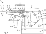
- Fig. 1 shows as an example of a hand-held machine tool schematically a hammer drill 1.
- the hammer drill 1 has a tool holder 2, in which a drill 3 or other tool can be used and locked.
- the exemplary hammer drill 1 has a rotary drive 4, which rotatably drives the tool holder 2 about its working axis 5 .
- the rotary drive 4 is based on an electric motor 6, which the user can switch on and off via an operating button 7 .
- An additional striking mechanism 8 can strike the drill 3 periodically in a direction of impact 9 along the working axis 5 .
- the striking mechanism 8 is preferably driven by the same electric motor 6 .
- a power supply can be done via a battery 10 or a power line.
- the rotary drive 4 includes the electric motor 6.
- the electric motor 6 is coupled to the tool holder 2 via a drive train.
- the drive train has, for example, a reducing gear 11.
- a clutch 12 may be provided.
- the hammer drill 1 has a handle 14, which is typically attached to a tool holder 2 remote from the end of a machine housing 15 of the hammer drill 1 .
- An additional handle 16 can be fastened, for example, near the tool holder 2 . The user can guide and hold the hammer drill 1 with the handle 14 during drilling.
- the user can turn the rotary drive 4 with the operating button 7 and off.
- the exemplary operation button 7 has a deactivating switch position and one or more activating switch positions.
- the operating button 7 is monostable in the deactivating switching position.
- the user must keep pressed the operating button 7 , otherwise the rotary drive 4 switches off.
- the user can select one of the activating switch positions by selecting his actuation force.
- the different switching positions can be associated with different speeds or different torque of the rotary drive 4 .
- a motor control 17 is awakened when the operating button 7 is actuated.
- the motor control 17 controls the direction of rotation of the electric motor 6.
- the motor control 17 feeds a current in phase into the windings of the electric motor 6 in accordance with the forward direction.
- the forward direction is fixed in a hammer drill 1 immutable as in clockwise. In an electric screwdriver, the forward direction of operation is typically adjustable by a selector switch.
- the motor controller 17 controls the speed of the electric motor 6.
- the motor controller 17 controls the power consumption of the electric motor 6 to a desired value, whereby a set by the load speed is set.
- the motor controller 17 for example, provides a mean current by means of a pulse width modulation.
- the motor controller 17 can adjust the power consumption such that a constant speed is established.
- the limitation of the power consumption or the speed can be specified, for example, by the user and the strength of the operation of the operating button 7 .
- the rotary drive 4 rotates , typically in a clockwise direction.
- the right-handed direction of rotation has established itself as the standard for drilling and setting screws.
- the user typically has a small amount of retroactive torque resulting from the resistance of rock to the rotating drill bit 3 .
- the user can apply the necessary holding power effortlessly or with little effort.
- the drill bit 3 can block in the borehole, thereby providing a high torque is applied to the tool holder 2 in consequence of the continued rotating the rotary drive. 4
- the retroactive torque can rise jerkily and in consequence damage the user and the hammer drill 1 .
- a protective device 18 In order to prevent injury to the user and damage to the hammer drill 1 monitors a protective device 18, the behavior of the hammer drill 1 and causes an expected or occurred blockade a protective measure 19, which interrupts the predetermined by the operating button 7 operation of the hammer drill 1 .
- the safety device 18 includes a movement sensor 20.
- the movement sensor 20 is preferably located on the working axis 5.
- the movement sensor 20 may be arranged, for example, on or near the handle 16 .
- the motion sensor 20 detects a rotational movement of the handle 14 about the working axis 5.
- An exemplary Motion sensor 20 is a gyro sensor which directly determines an angular velocity based on a Coriolis force exerted by the rotational motion.
- the Gryrosensor may for example contain a vibrating plate, the oscillation frequency is changed by the Coriolis force.
- An alternative motion sensor 20 detects an acceleration at two offset locations in the hammer drill 1 and determines the rotational movement of the hammer drill 1 from the difference .
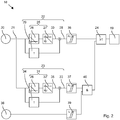
- An output signal 21 from the motion sensor 20 is a measure of the rotational speed w or angular velocity of the handle 14 about the working axis 5.
- the output signal 21 is applied to a first fast motion motion estimator 22 and a second slow motion motion estimator 23 .
- the protection measure 19 may be triggered independently of the first motion estimator 22 and the second motion estimator 23 as symbolically represented by the logical OR gate 24 .
- the first motion estimator 22 includes a (first) band limited integrator 25.
- the band limited integrator 25 has a (first) cutoff frequency w1 in the range between 300 mHz and 1000 mHz.
- the low limit frequency w1 suppresses slow rotational movements of the handle 14, which are typically initiated by the user.
- Fast rotational movements which are typically not triggered by a user but indicate a blockage of the drill 3 , are integrated.
- angular speeds of the handle 14 are on the order of the speed of the tool holder caused by a blockage.
- the typical rotational speeds are in the range between 2 Hz and 20 Hz, the associated angular velocities in the event of a blockage being, for example, in the range of 500 degrees / s to 5,000 degrees / s.
- the band-limited integrator 25 is represented symbolically by an unlimited integrator 26 and a high-pass filter 27 .
- the cut- off frequency w1 of the high-pass filter 27 corresponds to the cut- off frequency w1 of the band-limited integrator 25.
- the cut- off frequency w1 denotes the frequency at which the output signal 21 of the high-pass filter 27 is attenuated by 3dB.
- the band-limited integrator 25 can be realized digitally or analogously.
- the output signal 21 of the motion sensor 20 is scanned time-discrete.
- a digital integrator 25 can be implemented by means of a discrete circuit or as a routine in a microprocessor.
- the (first) output 28 of the first motion estimator 22 is an estimate of the angle of rotation by which the hammer 1 or handle 16 has rotated within a short period of time.
- the cut- off frequency w1 limits the considered time period or weights rotational movements outside of the time period with very small factors.
- the exemplary first motion estimator 22 has an additional proportional component 29 that multiplies the current angular velocity by a fixed time constant T. By means of the proportional component 29 , it is estimated how far the handle 16 will continue to rotate within a future period of time.
- the proportional component 29 and the output signal 30 of the band-limited integrator 25 are added to the output signal 28 of the first motion estimator 22 .
- the second motion estimator 23 includes a (second) band-limited integrator 31.
- the structure of the second band-limited integrator 31 is equal to the structure of the first band-limited integrator 25.
- a (second) cut-off frequency w2 of the integrator 31 is selected such that the second motion estimator 23 rotational movements with a lower angular velocity of 20 degrees / s integrated.
- the second cutoff frequency w2 is preferably at most 1/10, preferably at most 1/100 of the first cutoff frequency w1.
- the second cutoff frequency w2 is in the range between 2 mHz and 10 mHz.
- the gain of the first band-limited integrator 25 and the second band-limited integrator 31 is preferably the same above the second limit frequency w2 .
- a cutoff frequency w2 of the high pass filter 32 corresponds to the second cutoff frequency w2.
- the (second) output signal 33 of the second motion estimator 23 in an estimate of the angle of rotation by which the hammer drill 1 or the handle 16 has rotated about the working axis 5 .
- the second motion estimator 23 also takes into account slow rotational movements. As a result, further rotations that are located further back in the past are taken into account significantly.
- the second motion estimator 23 can likewise have a proportional component 34 , which is preferably identical to the proportional component 29 of the first motion estimator 22 , in particular with the same time constant T.
- the output signal 33 of the second motion estimator 23 is based on the sum of the output signal 35 of the second band-limited integrator 31 and the proportional component 34.
- the protective device 18 has realized a first triggering threshold A1, for example by a (first) discriminator 36 , with which the output signal 28 of the first motion estimator 22 is compared. If the output signal exceeds the triggering threshold A1 , the protective measure 19 is initiated.
- the first triggering threshold A1 corresponds to a rotation angle of at most 50 degrees, preferably at least 10 degrees.
- the protection device 18 is activated when the first motion estimator 22 has detected an average rotation of more than 50 degrees or expects a rotation of more than 50 degrees within the time period.
- the protective device 18 has realized a second triggering threshold A2, for example by a (second) discriminator 37 , with which the second output signal 33 of the second motion estimator 23 is compared.
- the second triggering threshold A2 corresponds to a rotation angle between 90 degrees and 120 degrees.
- the second triggering threshold A2 is greater than the first triggering threshold.
- the rotation of the handle 14 is at an angular velocity, which allows the user to react.
- the time span within which the handle 16 is rotated by a rotation angle of 50 degrees is greater than the typical human response time of 200 ms to 400 ms.
- Exceeding the second triggering threshold A2 is only one condition for the initiation of the protective measure 19.
- the second condition is the exceeding of a power threshold by the power output of the rotary drive 4.
- the power output is detected by a power sensor 38 .
- the power output can be determined indirectly, for example, by the power consumption of the electric motor 6 . Further, the power output may be determined based on the torque exerted by the rotary drive 4 and the speed thereof.
- the power threshold L is, for example, above 200 watts.
- a discriminator 39 compares the current power output with the power threshold L.
- the protection measure 19 is triggered when both the first condition and the second condition are met, represented symbolically by the AND gate 40 .
- the protective measure 19 may include a mechanical interruption of the rotary drive 4 by means of the coupling 12 .
- the clutch 12 is correspondingly switchable via an actuator, for example via a magnetic coil.
- the electric motor 6 can be braked.
- the braking of an electric motor 6 takes place, for example, by short-circuiting the rotor windings or short-circuiting the stator windings via a load resistor.
- the braking of the electric motor 6 can be controlled by a motor controller 17 .
- the striking mechanism 8 is, for example, a pneumatic striking mechanism.
- An excitation piston 41 is forced by the electric motor 6 in a periodic back and forth movement along the working axis 5 .
- a running on the working axis 5 racket 42 is coupled via an air spring to the excitation piston 41 .
- the air spring is formed by a closed by the exciter piston 41 and the bat 42 pneumatic chamber 43 .
- the exciter piston 41 and the racket 42 may be guided in a guide tube 44 which at the same time terminates the pneumatic chamber 43 in the radial direction.
- An anvil 45 may be arranged in the direction of impact 9 of the racket 42 .
- the bat 42 strikes the striker 45, which forwards the blow to the drill 3 located in the tool holder 2 .
Landscapes
- Engineering & Computer Science (AREA)
- Mechanical Engineering (AREA)
- Percussive Tools And Related Accessories (AREA)
Claims (6)
- Procédé de commande d'une machine-outil (1) pour des outils rotatifs, comportant les étapes consistant à :faire tourner en continu un porte-outil (2) au moyen d'un mécanisme d'entraînement en rotation (4) autour d'un axe de travail (5) en réponse à un actionnement d'un bouton-poussoir de commande (7),détecter un mouvement de rotation d'une poignée (14) autour de l'axe de travail (5) au moyen d'un capteur de mouvement (20),estimer un premier angle de rotation (28) de la poignée (14) au moyen d'un premier estimateur de mouvement (22) qui ignore de mouvements de rotation lents inférieurs à une valeur limite,estimer un second angle de rotation (32) de la poignée (14) au moyen d'un second estimateur de mouvement (23) qui tient compte des mouvements de rotation lents inférieurs à la valeur limite,activer une mesure de protection (19) pour réduire le couple de sortie du mécanisme d'entraînement en rotation (4) lorsque le premier angle de rotation (28) franchit un premier seuil de déclenchement (A1),activer la mesure de protection (19) pour réduire le couple de sortie du mécanisme d'entraînement en rotation (4) lorsque le second angle de rotation (33) franchit un second seuil de déclenchement (A2) et qu'une puissance de sortie du mécanisme d'entraînement en rotation (4) franchit simultanément un seuil de puissance (L) .
- Procédé de commande selon la revendication 1, caractérisé en ce que la valeur limite est dans une plage comprise entre 10 degrés/s et 50 degrés/s.
- Procédé de commande selon la revendication 1 ou 2, caractérisé en ce que l'estimation d'un premier angle de rotation (28) de la poignée (14) au moyen du premier estimateur de mouvement (22) ignore des mouvements de rotation lents inférieurs à une première valeur limite, l'estimation d'un second angle de rotation (32) de la poignée (14) au moyen du second estimateur de mouvement (23) tient compte de mouvements de rotation lents inférieurs à une seconde valeur limite, dans lequel la seconde valeur limite est inférieure à 10 % de la première valeur limite.
- Procédé de commande selon l'une des revendications précédentes, caractérisé en ce que le premier estimateur de mouvement (22) contient un intégrateur à bande limitée (25) ayant une première fréquence limite (w1) et le second estimateur de mouvement (23) contient un intégrateur à bande limitée (31) ayant une seconde fréquence limite (w2), dans lequel la première fréquence limite (w1) est au moins dix fois supérieure à la seconde fréquence limite (w2).
- Procédé de commande selon l'une des revendications précédentes, caractérisé en ce que le premier seuil de déclenchement (A1) est inférieur au second seuil de déclenchement (A2).
- Procédé de commande selon la revendication 5, caractérisé en ce que le premier seuil de déclenchement (A1) est inférieur à 50 degrés et le second seuil de déclenchement (A2) est supérieur à 90 degrés.
Applications Claiming Priority (2)
| Application Number | Priority Date | Filing Date | Title |
|---|---|---|---|
| EP16153432.6A EP3199303A1 (fr) | 2016-01-29 | 2016-01-29 | Machine-outil portative |
| PCT/EP2017/051364 WO2017129538A1 (fr) | 2016-01-29 | 2017-01-24 | Machine-outil portative |
Publications (2)
| Publication Number | Publication Date |
|---|---|
| EP3408057A1 EP3408057A1 (fr) | 2018-12-05 |
| EP3408057B1 true EP3408057B1 (fr) | 2019-10-09 |
Family
ID=55274998
Family Applications (2)
| Application Number | Title | Priority Date | Filing Date |
|---|---|---|---|
| EP16153432.6A Withdrawn EP3199303A1 (fr) | 2016-01-29 | 2016-01-29 | Machine-outil portative |
| EP17701134.3A Active EP3408057B1 (fr) | 2016-01-29 | 2017-01-24 | Machine-outil portative |
Family Applications Before (1)
| Application Number | Title | Priority Date | Filing Date |
|---|---|---|---|
| EP16153432.6A Withdrawn EP3199303A1 (fr) | 2016-01-29 | 2016-01-29 | Machine-outil portative |
Country Status (4)
| Country | Link |
|---|---|
| US (1) | US10688614B2 (fr) |
| EP (2) | EP3199303A1 (fr) |
| JP (1) | JP6709580B2 (fr) |
| WO (1) | WO2017129538A1 (fr) |
Families Citing this family (12)
| Publication number | Priority date | Publication date | Assignee | Title |
|---|---|---|---|---|
| JP6981744B2 (ja) | 2016-10-07 | 2021-12-17 | 株式会社マキタ | ハンマドリル |
| JP6757226B2 (ja) * | 2016-10-07 | 2020-09-16 | 株式会社マキタ | 電動工具 |
| CN109315106A (zh) * | 2017-08-01 | 2019-02-12 | 创科(澳门离岸商业服务)有限公司 | 螺旋挖眼机 |
| DE102018208636A1 (de) * | 2018-05-30 | 2019-12-05 | Robert Bosch Gmbh | Verfahren zur elektronischen Erfassung eines Überrastungszustands einer Kupplungseinheit |
| EP3581337A1 (fr) * | 2018-06-11 | 2019-12-18 | HILTI Aktiengesellschaft | Machine-outil portative |
| EP3593951A1 (fr) * | 2018-07-11 | 2020-01-15 | Hilti Aktiengesellschaft | Machine-outil portative |
| US11453093B2 (en) | 2019-06-24 | 2022-09-27 | Black & Decker Inc. | Reciprocating tool having planetary gear assembly and counterweighting assembly |
| US11229963B2 (en) * | 2019-06-24 | 2022-01-25 | Black & Decker Inc. | Force and moment canceling reciprocating mechanism and power tool having same |
| US11498198B2 (en) * | 2019-08-20 | 2022-11-15 | The Boeing Company | Ergonomic handle for a power tool |
| EP4082721A1 (fr) * | 2021-04-26 | 2022-11-02 | Hilti Aktiengesellschaft | Procédé d'activation et de désactivation d'un verrouillage de broche dans une machine-outil et machine-outil |
| US11958121B2 (en) | 2022-03-04 | 2024-04-16 | Black & Decker Inc. | Reciprocating tool having orbit function |
| US11839964B2 (en) | 2022-03-09 | 2023-12-12 | Black & Decker Inc. | Counterbalancing mechanism and power tool having same |
Family Cites Families (41)
| Publication number | Priority date | Publication date | Assignee | Title |
|---|---|---|---|---|
| DE2442260A1 (de) * | 1974-09-04 | 1976-03-18 | Bosch Gmbh Robert | Handwerkzeugmaschine |
| US4267914A (en) * | 1979-04-26 | 1981-05-19 | Black & Decker Inc. | Anti-kickback power tool control |
| FR2598110B2 (fr) * | 1985-10-24 | 1989-11-03 | Black & Decker Inc | Tournevis motorise perfectionne |
| GB9320181D0 (en) * | 1993-09-30 | 1993-11-17 | Black & Decker Inc | Improvements in and relating to power tools |
| DE4344817C2 (de) * | 1993-12-28 | 1995-11-16 | Hilti Ag | Verfahren und Einrichtung für handgeführte Werkzeugmaschinen zur Vermeidung von Unfällen durch Werkzeugblockieren |
| EP0771619B2 (fr) * | 1995-11-02 | 2004-11-10 | Robert Bosch Gmbh | Procédé d'interruption de l'entraínement d'un outil à main et outil à main correspondant |
| DE19540718B4 (de) * | 1995-11-02 | 2007-04-05 | Robert Bosch Gmbh | Handwerkzeugmaschine mit einer von einer Detektionseinrichtung auslösbaren Blockiereinrichtung |
| DE19857061C2 (de) * | 1998-12-10 | 2000-11-02 | Hilti Ag | Verfahren und Einrichtung zur Vermeidung von Unfällen bei handgeführten Werkzeugmaschinen durch Werkzeugblockieren |
| DE19900882A1 (de) * | 1999-01-12 | 2000-07-13 | Bosch Gmbh Robert | Handwerkzeugmaschine |
| DE10051775A1 (de) | 2000-10-19 | 2002-05-16 | Hilti Ag | Sicherheitsschaltung für drehendes Elektrohandwerkzeuggerät |
| DE10117121A1 (de) * | 2001-04-06 | 2002-10-17 | Bosch Gmbh Robert | Handwerkzeugmaschine |
| DE10160864A1 (de) * | 2001-12-12 | 2003-06-26 | Hilti Ag | Axial schlagendes Elektrohandwerkzeuggerät |
| EP1447177B1 (fr) * | 2003-02-05 | 2011-04-20 | Makita Corporation | Outil motorisé à limitation de couple n'utilisant qu'un moyen de détection de déplacement angulaire |
| US7395871B2 (en) * | 2003-04-24 | 2008-07-08 | Black & Decker Inc. | Method for detecting a bit jam condition using a freely rotatable inertial mass |
| JP2005103648A (ja) * | 2003-09-10 | 2005-04-21 | Aisin Aw Co Ltd | 回転移送装置、それを用いたねじ螺合装置、カシメ装置及び押着装置 |
| US7552781B2 (en) * | 2004-10-20 | 2009-06-30 | Black & Decker Inc. | Power tool anti-kickback system with rotational rate sensor |
| US7410006B2 (en) * | 2004-10-20 | 2008-08-12 | Black & Decker Inc. | Power tool anti-kickback system with rotational rate sensor |
| US7403131B2 (en) * | 2005-06-21 | 2008-07-22 | The Boeing Company | Power tool movement monitor and operating system |
| CN101091998B (zh) * | 2006-06-19 | 2012-03-28 | 苏州宝时得电动工具有限公司 | 变速工具 |
| EP2030709A3 (fr) * | 2007-08-29 | 2013-01-16 | Positec Power Tools (Suzhou) Co., Ltd. | Outil électrique |
| CN101676052B (zh) * | 2008-09-19 | 2013-10-30 | 德昌电机(深圳)有限公司 | 带力度感应装置的电钻 |
| JP5441003B2 (ja) * | 2009-10-01 | 2014-03-12 | 日立工機株式会社 | 回転打撃工具 |
| DE102009046789A1 (de) * | 2009-11-17 | 2011-05-19 | Robert Bosch Gmbh | Handwerkzeugmaschinenvorrichtung |
| DE102009054762A1 (de) * | 2009-12-16 | 2011-06-22 | Hilti Aktiengesellschaft | Steuerungsverfahren für eine handgeführte Werkzeugmaschine und Werkzeugmaschine |
| US8875804B2 (en) * | 2010-01-07 | 2014-11-04 | Black & Decker Inc. | Screwdriving tool having a driving tool with a removable contact trip assembly |
| JP2013516335A (ja) * | 2010-01-07 | 2013-05-13 | ブラック アンド デッカー インク | 回転入力制御機能を有する動力スクリュードライバ |
| US8418778B2 (en) * | 2010-01-07 | 2013-04-16 | Black & Decker Inc. | Power screwdriver having rotary input control |
| DE102010027981A1 (de) * | 2010-04-20 | 2011-10-20 | Robert Bosch Gmbh | Winkelschleifer |
| JP5686236B2 (ja) * | 2010-07-30 | 2015-03-18 | 日立工機株式会社 | 電動工具及びネジ締め用電動工具 |
| DE102011004364A1 (de) * | 2011-02-18 | 2012-08-23 | Robert Bosch Gmbh | Handwerkzeugmaschine, insbesondere Akkuschrauber |
| JP5802149B2 (ja) * | 2012-02-24 | 2015-10-28 | 株式会社モリタ製作所 | 歯科用治療装置 |
| US20140053419A1 (en) | 2012-08-06 | 2014-02-27 | Black & Decker Inc. | Control circuit for reciprocating saws |
| US20140166323A1 (en) * | 2012-09-16 | 2014-06-19 | J. Carl Cooper | Kickback Reduction for Power Tools and Machines |
| DE102013200602B4 (de) * | 2013-01-16 | 2023-07-13 | Robert Bosch Gmbh | Elektrowerkzeug mit verbesserter Bedienbarkeit |
| DE102014202585A1 (de) * | 2013-04-29 | 2014-10-30 | Robert Bosch Gmbh | Handwerkzeugbedieneinheit |
| DE202014102422U1 (de) * | 2013-05-31 | 2014-08-08 | Hitachi Koki Co., Ltd. | Elektroleistungswerkzeug |
| DE102013224759A1 (de) * | 2013-12-03 | 2015-06-03 | Robert Bosch Gmbh | Werkzeugmaschinenvorrichtung |
| JP6304533B2 (ja) * | 2014-03-04 | 2018-04-04 | パナソニックIpマネジメント株式会社 | インパクト回転工具 |
| JP6053714B2 (ja) * | 2014-03-31 | 2016-12-27 | 日立建機株式会社 | 油圧ショベル |
| JP2017001115A (ja) * | 2015-06-05 | 2017-01-05 | 株式会社マキタ | 作業工具 |
| JP2018199180A (ja) * | 2017-05-26 | 2018-12-20 | 株式会社マキタ | 電動作業機 |
-
2016
- 2016-01-29 EP EP16153432.6A patent/EP3199303A1/fr not_active Withdrawn
-
2017
- 2017-01-24 EP EP17701134.3A patent/EP3408057B1/fr active Active
- 2017-01-24 US US16/070,565 patent/US10688614B2/en active Active
- 2017-01-24 JP JP2018538857A patent/JP6709580B2/ja active Active
- 2017-01-24 WO PCT/EP2017/051364 patent/WO2017129538A1/fr active Application Filing
Non-Patent Citations (1)
| Title |
|---|
| None * |
Also Published As
| Publication number | Publication date |
|---|---|
| US20190061081A1 (en) | 2019-02-28 |
| EP3199303A1 (fr) | 2017-08-02 |
| US10688614B2 (en) | 2020-06-23 |
| WO2017129538A1 (fr) | 2017-08-03 |
| JP2019507024A (ja) | 2019-03-14 |
| JP6709580B2 (ja) | 2020-06-17 |
| EP3408057A1 (fr) | 2018-12-05 |
Similar Documents
| Publication | Publication Date | Title |
|---|---|---|
| EP3408057B1 (fr) | Machine-outil portative | |
| EP3377271B1 (fr) | Procédé de commande de machine-outil | |
| EP1452278B1 (fr) | Méthode de contrôle d'un marteau électrique à percussion | |
| EP2338646B1 (fr) | Procédé de commande pour une machine-outil manuelle | |
| EP1240964B1 (fr) | Outil à main avec arrêt électronique | |
| EP3221088B1 (fr) | Procédé de commande d'une perceuse | |
| WO2002081153A1 (fr) | Machine-outil a main | |
| EP3221090B1 (fr) | Procédé de commande pour une machine-outils manuelle | |
| EP0303651A1 (fr) | Procede d'interruption de l'entrainement, en particulier en percussion et/ou en rotation, d'un outil a main. | |
| EP3266567A1 (fr) | Machine-outil portative | |
| EP2517839B1 (fr) | Machine-outil et procédé de commande | |
| EP3288734A1 (fr) | Génération adaptative de paramètres de forage lors d'une opération de carottage automatisé | |
| DE3707052A1 (de) | Verfahren zum unterbrechen der antriebstaetigkeit, insbesondere drehantriebstaetigkeit, einer handwerkzeugmaschine | |
| DE112019005777T5 (de) | Drehwerkzeug | |
| EP4377049A1 (fr) | Procédé de commande en boucle ouverte et en boucle fermée d'une machine-outil | |
| WO2016059017A1 (fr) | Machine-outil portative de burinage | |
| EP2921263A1 (fr) | Reconnaissance de comportement au choc en fonction de la charge | |
| WO2020058031A1 (fr) | Machine-outil portative et procédé pour faire fonctionner une machine-outil portative | |
| EP4353387A1 (fr) | Procédé de maintien d'une broche d'une machine-outil mobile | |
| DE10361225A1 (de) | Drehende Elektrohandwerkzeugmaschine und Sicherheitsroutine |
Legal Events
| Date | Code | Title | Description |
|---|---|---|---|
| STAA | Information on the status of an ep patent application or granted ep patent |
Free format text: STATUS: UNKNOWN |
|
| STAA | Information on the status of an ep patent application or granted ep patent |
Free format text: STATUS: THE INTERNATIONAL PUBLICATION HAS BEEN MADE |
|
| PUAI | Public reference made under article 153(3) epc to a published international application that has entered the european phase |
Free format text: ORIGINAL CODE: 0009012 |
|
| STAA | Information on the status of an ep patent application or granted ep patent |
Free format text: STATUS: REQUEST FOR EXAMINATION WAS MADE |
|
| 17P | Request for examination filed |
Effective date: 20180829 |
|
| AK | Designated contracting states |
Kind code of ref document: A1 Designated state(s): AL AT BE BG CH CY CZ DE DK EE ES FI FR GB GR HR HU IE IS IT LI LT LU LV MC MK MT NL NO PL PT RO RS SE SI SK SM TR |
|
| AX | Request for extension of the european patent |
Extension state: BA ME |
|
| DAV | Request for validation of the european patent (deleted) | ||
| DAX | Request for extension of the european patent (deleted) | ||
| GRAP | Despatch of communication of intention to grant a patent |
Free format text: ORIGINAL CODE: EPIDOSNIGR1 |
|
| STAA | Information on the status of an ep patent application or granted ep patent |
Free format text: STATUS: GRANT OF PATENT IS INTENDED |
|
| INTG | Intention to grant announced |
Effective date: 20190708 |
|
| GRAS | Grant fee paid |
Free format text: ORIGINAL CODE: EPIDOSNIGR3 |
|
| GRAA | (expected) grant |
Free format text: ORIGINAL CODE: 0009210 |
|
| STAA | Information on the status of an ep patent application or granted ep patent |
Free format text: STATUS: THE PATENT HAS BEEN GRANTED |
|
| AK | Designated contracting states |
Kind code of ref document: B1 Designated state(s): AL AT BE BG CH CY CZ DE DK EE ES FI FR GB GR HR HU IE IS IT LI LT LU LV MC MK MT NL NO PL PT RO RS SE SI SK SM TR |
|
| REG | Reference to a national code |
Ref country code: GB Ref legal event code: FG4D Free format text: NOT ENGLISH |
|
| REG | Reference to a national code |
Ref country code: CH Ref legal event code: EP |
|
| REG | Reference to a national code |
Ref country code: DE Ref legal event code: R096 Ref document number: 502017002524 Country of ref document: DE |
|
| REG | Reference to a national code |
Ref country code: IE Ref legal event code: FG4D Free format text: LANGUAGE OF EP DOCUMENT: GERMAN |
|
| REG | Reference to a national code |
Ref country code: AT Ref legal event code: REF Ref document number: 1188249 Country of ref document: AT Kind code of ref document: T Effective date: 20191115 |
|
| REG | Reference to a national code |
Ref country code: NL Ref legal event code: MP Effective date: 20191009 |
|
| REG | Reference to a national code |
Ref country code: LT Ref legal event code: MG4D |
|
| PG25 | Lapsed in a contracting state [announced via postgrant information from national office to epo] |
Ref country code: NL Free format text: LAPSE BECAUSE OF FAILURE TO SUBMIT A TRANSLATION OF THE DESCRIPTION OR TO PAY THE FEE WITHIN THE PRESCRIBED TIME-LIMIT Effective date: 20191009 Ref country code: LV Free format text: LAPSE BECAUSE OF FAILURE TO SUBMIT A TRANSLATION OF THE DESCRIPTION OR TO PAY THE FEE WITHIN THE PRESCRIBED TIME-LIMIT Effective date: 20191009 Ref country code: SE Free format text: LAPSE BECAUSE OF FAILURE TO SUBMIT A TRANSLATION OF THE DESCRIPTION OR TO PAY THE FEE WITHIN THE PRESCRIBED TIME-LIMIT Effective date: 20191009 Ref country code: PL Free format text: LAPSE BECAUSE OF FAILURE TO SUBMIT A TRANSLATION OF THE DESCRIPTION OR TO PAY THE FEE WITHIN THE PRESCRIBED TIME-LIMIT Effective date: 20191009 Ref country code: NO Free format text: LAPSE BECAUSE OF FAILURE TO SUBMIT A TRANSLATION OF THE DESCRIPTION OR TO PAY THE FEE WITHIN THE PRESCRIBED TIME-LIMIT Effective date: 20200109 Ref country code: FI Free format text: LAPSE BECAUSE OF FAILURE TO SUBMIT A TRANSLATION OF THE DESCRIPTION OR TO PAY THE FEE WITHIN THE PRESCRIBED TIME-LIMIT Effective date: 20191009 Ref country code: BG Free format text: LAPSE BECAUSE OF FAILURE TO SUBMIT A TRANSLATION OF THE DESCRIPTION OR TO PAY THE FEE WITHIN THE PRESCRIBED TIME-LIMIT Effective date: 20200109 Ref country code: GR Free format text: LAPSE BECAUSE OF FAILURE TO SUBMIT A TRANSLATION OF THE DESCRIPTION OR TO PAY THE FEE WITHIN THE PRESCRIBED TIME-LIMIT Effective date: 20200110 Ref country code: PT Free format text: LAPSE BECAUSE OF FAILURE TO SUBMIT A TRANSLATION OF THE DESCRIPTION OR TO PAY THE FEE WITHIN THE PRESCRIBED TIME-LIMIT Effective date: 20200210 Ref country code: ES Free format text: LAPSE BECAUSE OF FAILURE TO SUBMIT A TRANSLATION OF THE DESCRIPTION OR TO PAY THE FEE WITHIN THE PRESCRIBED TIME-LIMIT Effective date: 20191009 Ref country code: LT Free format text: LAPSE BECAUSE OF FAILURE TO SUBMIT A TRANSLATION OF THE DESCRIPTION OR TO PAY THE FEE WITHIN THE PRESCRIBED TIME-LIMIT Effective date: 20191009 |
|
| PG25 | Lapsed in a contracting state [announced via postgrant information from national office to epo] |
Ref country code: IS Free format text: LAPSE BECAUSE OF FAILURE TO SUBMIT A TRANSLATION OF THE DESCRIPTION OR TO PAY THE FEE WITHIN THE PRESCRIBED TIME-LIMIT Effective date: 20200224 Ref country code: HR Free format text: LAPSE BECAUSE OF FAILURE TO SUBMIT A TRANSLATION OF THE DESCRIPTION OR TO PAY THE FEE WITHIN THE PRESCRIBED TIME-LIMIT Effective date: 20191009 Ref country code: RS Free format text: LAPSE BECAUSE OF FAILURE TO SUBMIT A TRANSLATION OF THE DESCRIPTION OR TO PAY THE FEE WITHIN THE PRESCRIBED TIME-LIMIT Effective date: 20191009 |
|
| PG25 | Lapsed in a contracting state [announced via postgrant information from national office to epo] |
Ref country code: AL Free format text: LAPSE BECAUSE OF FAILURE TO SUBMIT A TRANSLATION OF THE DESCRIPTION OR TO PAY THE FEE WITHIN THE PRESCRIBED TIME-LIMIT Effective date: 20191009 |
|
| REG | Reference to a national code |
Ref country code: DE Ref legal event code: R097 Ref document number: 502017002524 Country of ref document: DE |
|
| PG2D | Information on lapse in contracting state deleted |
Ref country code: IS |
|
| PG25 | Lapsed in a contracting state [announced via postgrant information from national office to epo] |
Ref country code: CZ Free format text: LAPSE BECAUSE OF FAILURE TO SUBMIT A TRANSLATION OF THE DESCRIPTION OR TO PAY THE FEE WITHIN THE PRESCRIBED TIME-LIMIT Effective date: 20191009 Ref country code: RO Free format text: LAPSE BECAUSE OF FAILURE TO SUBMIT A TRANSLATION OF THE DESCRIPTION OR TO PAY THE FEE WITHIN THE PRESCRIBED TIME-LIMIT Effective date: 20191009 Ref country code: EE Free format text: LAPSE BECAUSE OF FAILURE TO SUBMIT A TRANSLATION OF THE DESCRIPTION OR TO PAY THE FEE WITHIN THE PRESCRIBED TIME-LIMIT Effective date: 20191009 Ref country code: DK Free format text: LAPSE BECAUSE OF FAILURE TO SUBMIT A TRANSLATION OF THE DESCRIPTION OR TO PAY THE FEE WITHIN THE PRESCRIBED TIME-LIMIT Effective date: 20191009 Ref country code: IS Free format text: LAPSE BECAUSE OF FAILURE TO SUBMIT A TRANSLATION OF THE DESCRIPTION OR TO PAY THE FEE WITHIN THE PRESCRIBED TIME-LIMIT Effective date: 20200209 |
|
| PLBE | No opposition filed within time limit |
Free format text: ORIGINAL CODE: 0009261 |
|
| STAA | Information on the status of an ep patent application or granted ep patent |
Free format text: STATUS: NO OPPOSITION FILED WITHIN TIME LIMIT |
|
| PG25 | Lapsed in a contracting state [announced via postgrant information from national office to epo] |
Ref country code: IT Free format text: LAPSE BECAUSE OF FAILURE TO SUBMIT A TRANSLATION OF THE DESCRIPTION OR TO PAY THE FEE WITHIN THE PRESCRIBED TIME-LIMIT Effective date: 20191009 Ref country code: SM Free format text: LAPSE BECAUSE OF FAILURE TO SUBMIT A TRANSLATION OF THE DESCRIPTION OR TO PAY THE FEE WITHIN THE PRESCRIBED TIME-LIMIT Effective date: 20191009 Ref country code: MC Free format text: LAPSE BECAUSE OF FAILURE TO SUBMIT A TRANSLATION OF THE DESCRIPTION OR TO PAY THE FEE WITHIN THE PRESCRIBED TIME-LIMIT Effective date: 20191009 Ref country code: SK Free format text: LAPSE BECAUSE OF FAILURE TO SUBMIT A TRANSLATION OF THE DESCRIPTION OR TO PAY THE FEE WITHIN THE PRESCRIBED TIME-LIMIT Effective date: 20191009 |
|
| 26N | No opposition filed |
Effective date: 20200710 |
|
| REG | Reference to a national code |
Ref country code: BE Ref legal event code: MM Effective date: 20200131 |
|
| PG25 | Lapsed in a contracting state [announced via postgrant information from national office to epo] |
Ref country code: LU Free format text: LAPSE BECAUSE OF NON-PAYMENT OF DUE FEES Effective date: 20200124 |
|
| PG25 | Lapsed in a contracting state [announced via postgrant information from national office to epo] |
Ref country code: BE Free format text: LAPSE BECAUSE OF NON-PAYMENT OF DUE FEES Effective date: 20200131 Ref country code: SI Free format text: LAPSE BECAUSE OF FAILURE TO SUBMIT A TRANSLATION OF THE DESCRIPTION OR TO PAY THE FEE WITHIN THE PRESCRIBED TIME-LIMIT Effective date: 20191009 |
|
| PG25 | Lapsed in a contracting state [announced via postgrant information from national office to epo] |
Ref country code: IE Free format text: LAPSE BECAUSE OF NON-PAYMENT OF DUE FEES Effective date: 20200124 |
|
| PG25 | Lapsed in a contracting state [announced via postgrant information from national office to epo] |
Ref country code: TR Free format text: LAPSE BECAUSE OF FAILURE TO SUBMIT A TRANSLATION OF THE DESCRIPTION OR TO PAY THE FEE WITHIN THE PRESCRIBED TIME-LIMIT Effective date: 20191009 Ref country code: MT Free format text: LAPSE BECAUSE OF FAILURE TO SUBMIT A TRANSLATION OF THE DESCRIPTION OR TO PAY THE FEE WITHIN THE PRESCRIBED TIME-LIMIT Effective date: 20191009 Ref country code: CY Free format text: LAPSE BECAUSE OF FAILURE TO SUBMIT A TRANSLATION OF THE DESCRIPTION OR TO PAY THE FEE WITHIN THE PRESCRIBED TIME-LIMIT Effective date: 20191009 |
|
| PG25 | Lapsed in a contracting state [announced via postgrant information from national office to epo] |
Ref country code: MK Free format text: LAPSE BECAUSE OF FAILURE TO SUBMIT A TRANSLATION OF THE DESCRIPTION OR TO PAY THE FEE WITHIN THE PRESCRIBED TIME-LIMIT Effective date: 20191009 |
|
| PGFP | Annual fee paid to national office [announced via postgrant information from national office to epo] |
Ref country code: FR Payment date: 20230124 Year of fee payment: 7 |
|
| PGFP | Annual fee paid to national office [announced via postgrant information from national office to epo] |
Ref country code: AT Payment date: 20240122 Year of fee payment: 8 |
|
| PGFP | Annual fee paid to national office [announced via postgrant information from national office to epo] |
Ref country code: DE Payment date: 20240119 Year of fee payment: 8 Ref country code: GB Payment date: 20240119 Year of fee payment: 8 Ref country code: CH Payment date: 20240202 Year of fee payment: 8 |