EP3407837B1 - Helical bone graft containment cage - Google Patents
Helical bone graft containment cage Download PDFInfo
- Publication number
- EP3407837B1 EP3407837B1 EP17704122.5A EP17704122A EP3407837B1 EP 3407837 B1 EP3407837 B1 EP 3407837B1 EP 17704122 A EP17704122 A EP 17704122A EP 3407837 B1 EP3407837 B1 EP 3407837B1
- Authority
- EP
- European Patent Office
- Prior art keywords
- helical structures
- graft containment
- bone
- containment device
- helical
- Prior art date
- Legal status (The legal status is an assumption and is not a legal conclusion. Google has not performed a legal analysis and makes no representation as to the accuracy of the status listed.)
- Active
Links
Images


Classifications
-
- A—HUMAN NECESSITIES
- A61—MEDICAL OR VETERINARY SCIENCE; HYGIENE
- A61F—FILTERS IMPLANTABLE INTO BLOOD VESSELS; PROSTHESES; DEVICES PROVIDING PATENCY TO, OR PREVENTING COLLAPSING OF, TUBULAR STRUCTURES OF THE BODY, e.g. STENTS; ORTHOPAEDIC, NURSING OR CONTRACEPTIVE DEVICES; FOMENTATION; TREATMENT OR PROTECTION OF EYES OR EARS; BANDAGES, DRESSINGS OR ABSORBENT PADS; FIRST-AID KITS
- A61F2/00—Filters implantable into blood vessels; Prostheses, i.e. artificial substitutes or replacements for parts of the body; Appliances for connecting them with the body; Devices providing patency to, or preventing collapsing of, tubular structures of the body, e.g. stents
- A61F2/02—Prostheses implantable into the body
- A61F2/28—Bones
- A61F2/2846—Support means for bone substitute or for bone graft implants, e.g. membranes or plates for covering bone defects
-
- A—HUMAN NECESSITIES
- A61—MEDICAL OR VETERINARY SCIENCE; HYGIENE
- A61F—FILTERS IMPLANTABLE INTO BLOOD VESSELS; PROSTHESES; DEVICES PROVIDING PATENCY TO, OR PREVENTING COLLAPSING OF, TUBULAR STRUCTURES OF THE BODY, e.g. STENTS; ORTHOPAEDIC, NURSING OR CONTRACEPTIVE DEVICES; FOMENTATION; TREATMENT OR PROTECTION OF EYES OR EARS; BANDAGES, DRESSINGS OR ABSORBENT PADS; FIRST-AID KITS
- A61F2/00—Filters implantable into blood vessels; Prostheses, i.e. artificial substitutes or replacements for parts of the body; Appliances for connecting them with the body; Devices providing patency to, or preventing collapsing of, tubular structures of the body, e.g. stents
- A61F2/02—Prostheses implantable into the body
- A61F2/28—Bones
- A61F2/2803—Bones for mandibular reconstruction
-
- A—HUMAN NECESSITIES
- A61—MEDICAL OR VETERINARY SCIENCE; HYGIENE
- A61F—FILTERS IMPLANTABLE INTO BLOOD VESSELS; PROSTHESES; DEVICES PROVIDING PATENCY TO, OR PREVENTING COLLAPSING OF, TUBULAR STRUCTURES OF THE BODY, e.g. STENTS; ORTHOPAEDIC, NURSING OR CONTRACEPTIVE DEVICES; FOMENTATION; TREATMENT OR PROTECTION OF EYES OR EARS; BANDAGES, DRESSINGS OR ABSORBENT PADS; FIRST-AID KITS
- A61F2/00—Filters implantable into blood vessels; Prostheses, i.e. artificial substitutes or replacements for parts of the body; Appliances for connecting them with the body; Devices providing patency to, or preventing collapsing of, tubular structures of the body, e.g. stents
- A61F2/02—Prostheses implantable into the body
- A61F2/28—Bones
- A61F2002/2835—Bone graft implants for filling a bony defect or an endoprosthesis cavity, e.g. by synthetic material or biological material
-
- A—HUMAN NECESSITIES
- A61—MEDICAL OR VETERINARY SCIENCE; HYGIENE
- A61F—FILTERS IMPLANTABLE INTO BLOOD VESSELS; PROSTHESES; DEVICES PROVIDING PATENCY TO, OR PREVENTING COLLAPSING OF, TUBULAR STRUCTURES OF THE BODY, e.g. STENTS; ORTHOPAEDIC, NURSING OR CONTRACEPTIVE DEVICES; FOMENTATION; TREATMENT OR PROTECTION OF EYES OR EARS; BANDAGES, DRESSINGS OR ABSORBENT PADS; FIRST-AID KITS
- A61F2/00—Filters implantable into blood vessels; Prostheses, i.e. artificial substitutes or replacements for parts of the body; Appliances for connecting them with the body; Devices providing patency to, or preventing collapsing of, tubular structures of the body, e.g. stents
- A61F2/02—Prostheses implantable into the body
- A61F2/28—Bones
- A61F2/2846—Support means for bone substitute or for bone graft implants, e.g. membranes or plates for covering bone defects
- A61F2002/285—Fixation appliances for attaching bone substitute support means to underlying bone
-
- A—HUMAN NECESSITIES
- A61—MEDICAL OR VETERINARY SCIENCE; HYGIENE
- A61F—FILTERS IMPLANTABLE INTO BLOOD VESSELS; PROSTHESES; DEVICES PROVIDING PATENCY TO, OR PREVENTING COLLAPSING OF, TUBULAR STRUCTURES OF THE BODY, e.g. STENTS; ORTHOPAEDIC, NURSING OR CONTRACEPTIVE DEVICES; FOMENTATION; TREATMENT OR PROTECTION OF EYES OR EARS; BANDAGES, DRESSINGS OR ABSORBENT PADS; FIRST-AID KITS
- A61F2/00—Filters implantable into blood vessels; Prostheses, i.e. artificial substitutes or replacements for parts of the body; Appliances for connecting them with the body; Devices providing patency to, or preventing collapsing of, tubular structures of the body, e.g. stents
- A61F2/02—Prostheses implantable into the body
- A61F2/30—Joints
- A61F2002/30001—Additional features of subject-matter classified in A61F2/28, A61F2/30 and subgroups thereof
- A61F2002/30108—Shapes
- A61F2002/30199—Three-dimensional shapes
- A61F2002/30289—Three-dimensional shapes helically-coiled
-
- A—HUMAN NECESSITIES
- A61—MEDICAL OR VETERINARY SCIENCE; HYGIENE
- A61F—FILTERS IMPLANTABLE INTO BLOOD VESSELS; PROSTHESES; DEVICES PROVIDING PATENCY TO, OR PREVENTING COLLAPSING OF, TUBULAR STRUCTURES OF THE BODY, e.g. STENTS; ORTHOPAEDIC, NURSING OR CONTRACEPTIVE DEVICES; FOMENTATION; TREATMENT OR PROTECTION OF EYES OR EARS; BANDAGES, DRESSINGS OR ABSORBENT PADS; FIRST-AID KITS
- A61F2/00—Filters implantable into blood vessels; Prostheses, i.e. artificial substitutes or replacements for parts of the body; Appliances for connecting them with the body; Devices providing patency to, or preventing collapsing of, tubular structures of the body, e.g. stents
- A61F2/02—Prostheses implantable into the body
- A61F2/30—Joints
- A61F2002/30001—Additional features of subject-matter classified in A61F2/28, A61F2/30 and subgroups thereof
- A61F2002/30316—The prosthesis having different structural features at different locations within the same prosthesis; Connections between prosthetic parts; Special structural features of bone or joint prostheses not otherwise provided for
- A61F2002/30329—Connections or couplings between prosthetic parts, e.g. between modular parts; Connecting elements
- A61F2002/30383—Connections or couplings between prosthetic parts, e.g. between modular parts; Connecting elements made by laterally inserting a protrusion, e.g. a rib into a complementarily-shaped groove
- A61F2002/30403—Longitudinally-oriented cooperating ribs and grooves on mating lateral surfaces of a mainly longitudinal connection
-
- A—HUMAN NECESSITIES
- A61—MEDICAL OR VETERINARY SCIENCE; HYGIENE
- A61F—FILTERS IMPLANTABLE INTO BLOOD VESSELS; PROSTHESES; DEVICES PROVIDING PATENCY TO, OR PREVENTING COLLAPSING OF, TUBULAR STRUCTURES OF THE BODY, e.g. STENTS; ORTHOPAEDIC, NURSING OR CONTRACEPTIVE DEVICES; FOMENTATION; TREATMENT OR PROTECTION OF EYES OR EARS; BANDAGES, DRESSINGS OR ABSORBENT PADS; FIRST-AID KITS
- A61F2/00—Filters implantable into blood vessels; Prostheses, i.e. artificial substitutes or replacements for parts of the body; Appliances for connecting them with the body; Devices providing patency to, or preventing collapsing of, tubular structures of the body, e.g. stents
- A61F2/02—Prostheses implantable into the body
- A61F2/30—Joints
- A61F2002/30001—Additional features of subject-matter classified in A61F2/28, A61F2/30 and subgroups thereof
- A61F2002/30316—The prosthesis having different structural features at different locations within the same prosthesis; Connections between prosthetic parts; Special structural features of bone or joint prostheses not otherwise provided for
- A61F2002/30329—Connections or couplings between prosthetic parts, e.g. between modular parts; Connecting elements
- A61F2002/30471—Connections or couplings between prosthetic parts, e.g. between modular parts; Connecting elements connected by a hinged linkage mechanism, e.g. of the single-bar or multi-bar linkage type
-
- A—HUMAN NECESSITIES
- A61—MEDICAL OR VETERINARY SCIENCE; HYGIENE
- A61F—FILTERS IMPLANTABLE INTO BLOOD VESSELS; PROSTHESES; DEVICES PROVIDING PATENCY TO, OR PREVENTING COLLAPSING OF, TUBULAR STRUCTURES OF THE BODY, e.g. STENTS; ORTHOPAEDIC, NURSING OR CONTRACEPTIVE DEVICES; FOMENTATION; TREATMENT OR PROTECTION OF EYES OR EARS; BANDAGES, DRESSINGS OR ABSORBENT PADS; FIRST-AID KITS
- A61F2/00—Filters implantable into blood vessels; Prostheses, i.e. artificial substitutes or replacements for parts of the body; Appliances for connecting them with the body; Devices providing patency to, or preventing collapsing of, tubular structures of the body, e.g. stents
- A61F2/02—Prostheses implantable into the body
- A61F2/30—Joints
- A61F2002/30001—Additional features of subject-matter classified in A61F2/28, A61F2/30 and subgroups thereof
- A61F2002/30316—The prosthesis having different structural features at different locations within the same prosthesis; Connections between prosthetic parts; Special structural features of bone or joint prostheses not otherwise provided for
- A61F2002/30535—Special structural features of bone or joint prostheses not otherwise provided for
- A61F2002/30576—Special structural features of bone or joint prostheses not otherwise provided for with extending fixation tabs
- A61F2002/30578—Special structural features of bone or joint prostheses not otherwise provided for with extending fixation tabs having apertures, e.g. for receiving fixation screws
Definitions
- Mandible defects are often treated with bone grafts and/or implants such as, bone plates, to assist with healing.
- the bone grafts may be placed in the target area using any of a variety of methods. However, without a container for the bone graft, the graft may fall away from a target site before it can be incorporated by the body into the bone.
- the present invention which is defined in the appended claims, is directed to a bone graft containment device, comprising a body formed via one or more helical structures extending about a longitudinal axis of the body from a first end to a second end to define a channel extending longitudinally therethrough, the channel configured to receive a bone graft or bone graft substitute material therein, the one or more helical structures formed of a material permitting the body to be one of expanded, compressed and curved to fill a target space of a target bone, wherein the bone graft containment device further comprises fixation element receiving structures connecting at least two adjacent turns of the one or more helical structures.
- Document US4787906A discloses a bone graft containment device according to the preamble of claim 1.
- the present invention is also directed to a bone graft system, comprising the graft containment device captioned-above and a fixation plate sized and shaped to be positioned along a length of the graft containment device to attach the graft containment device to the bone, the attachment including openings extending therethrough for receiving fixation elements therethrough.
- a method for treating a bone comprising inserting a bone graft material into a channel of a graft containment device, the graft containment device including a body formed via one or more helical structures extending about a longitudinal axis of the body from a first end to a second end to define the channel, and one of expanding, compressing and bending the graft containment device to fill a target space of a target mandible bone and positioning the graft containment device in the target space.
- the present invention relates to the treatment of bone and, in particular, relates to treatments using bone grafts.
- Exemplary embodiments of the present invention describe a graft containment cage configured to be positioned in a gap or space formed in a bone (e.g., mandible) so that graft material may be packed therein to encourage and guide the generation of new bone within the space of the bone.
- the graft containment device of the exemplary embodiment is formed via a helical construction which allows for increased flexibility of individual struts of the device.
- the graft containment device of one embodiment is sized, shaped and structured to treat defects of the mandible.
- the exemplary embodiment is shown and described as useful in treating a mandible, it will be understood by those of skill in the art that the graft containment device of the present invention may also be formed in different shapes and sizes to permit its use in treating other types of bone which would benefit from the use of a graft containment device.
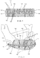
- a graft containment device 100 comprises a body 102 extending longitudinally from a first end 104 to a second end 106 and including a channel 108 extending therethrough.
- the body 102 may be formed via at least one helical structure 110 extending from the first end 104 to the second end 106.
- the device may include multiple helical structures with a first one of the helical structures 110 extending along only a part of the length of the device 100 while a second structure 110 extends along all or part of the length of the device 100.
- the helical structure 110 is wrapped about a longitudinal axis of the device 100 to form a perimeter of the device 100.
- the structure 110 extends around the longitudinal axis of the device 100 in a generally helical configuration defining the channel 108.
- the helical configuration refers generally to the wrapping of the structure 110 about the longitudinal axis at an angle relative to planes perpendicular to the longitudinal axis while the shape of the perimeter of the device 100 need not be strictly helical as the shape of the perimeter will be defined to mimic as closely as possible the shape of a portion of bone which is to be replaced by the graft.
- the body 102 of the graft containment device 100 is sized and shaped so that, when the graft containment device 100 is positioned in a target space or gap within a bone, the body 102 substantially matches an outer profile of the bone.
- the body 102 is sized and shaped to be positioned between two separated portions of a target bone so that each of the ends 104, 106 substantially matches a profile of an outer surface of a corresponding one of the ends of the separated portions of bone.
- the helical structure 110 permits the graft containment device 100 to be longitudinally compressed or expanded and/or curved to extend along a path of a portion of bone to be replaced. Graft material may be inserted into the channel 108 via the open first and second ends 104, 106.
- graft material may be inserted into the channel 108 via a space 112 between adjacent turns of the helical structure 110 or, where the graft containment device 100 includes more than one helical structure 110, a space 112 between adjacent helical structures 110.
- the space 112 may be enlarged to facilitate insertion of the bone graft material by moving adjacent turns of the one or more helical structures 110 away from one another.
- the body 102 of the graft containment device 100 extends longitudinally from the first end 104 to the second end 106 and generally defines a shape corresponding to the profile of the outer surface of the target bone - particularly the mandible.
- the body 102 is formed via a plurality of helical structures 110, first ends 104 of the helical structures 110 being connected to one another via a first connecting structure 116 and second ends 106 of the helical structures 110 connected to one another via a second connecting structure 118.
- the helical structures 110 extend about the longitudinal axis of the graft containment device 110 to define the channel 108.
- the body 102 may be substantially cylindrical and the first and second connecting structures 116, 118 may be configured as rings. It will be understood by those of skill in the art, however, that the body 102 along with the first and second connecting structures 116, 118 may have any of a variety of shapes to match an outer profile of the target space in which the graft containment device 100 is inserted. It will also be understood by those of skill in the art that the graft containment device 100 may be formed of a flexible material so that, even if the body 102 is not the exact shape of the target space which it is intended to fill, the graft containment device 100 may be flexed and deformed to fit the desired target space. For example, the graft containment device 100 may be formed of materials such as, Polycapralactone (PCL), Polylactide and/or Titanium.
- PCL Polycapralactone
- Titanium Titanium
- Figs. 1 - 3 show a graft containment device 100 formed of a plurality of helical structures 110, as described above, the graft containment device 100 may alternatively be formed from a single helical structure 110, as shown in Fig. 4 . Where the graft containment device 100 includes only a single helical structure 110, first and second connecting structures 116, 118 are not required.
- the graft containment device 100 may also include longitudinal struts 120 extending along at least a portion of a length of the body 102.
- the longitudinal struts 120 may be useful for strengthening and/or stiffening all or part of the body 102 and/or for the insertion of fixation elements 152.
- the graft containment device 100 may be used in conjunction with a fixation plate 150 or other attachment, as shown in Figs. 2 and 3 , which may be used to align separated portions of bone.
- the fixation plate 150 may be fixed to the graft containment device 100 and to the separated portions of bone, to form a bridge maintaining the separated portions of bone and the device 100 in a target alignment.
- the fixation plate 150 may be fixed to the graft containment device 100 via screws inserted through an opening in the fixation plate and into a space 122 between adjacent longitudinal struts 120.
- the graft containment device 100 should therefore include at least two longitudinal struts 120.
- the graft containment device 100 may include four longitudinal struts 120. It will be understood by those of skill in the art, however, that the graft containment device 100 may include any number of longitudinal struts 120.
- the struts 120 may be positioned as desired to aid in retaining the graft material within the device 100. For example, for certain applications in which a bone is generally oriented with one side facing downward (e.g., the mandible), the struts 120 may be placed along the bottom to prevent the migration of material out of the device 100 through the influence of gravity.
- the longitudinal struts 120 extend along an entire length of the body 102. In this embodiment, the longitudinal struts 120 prevent a length of the graft containment device 100 from being expanded or compressed while permitting the body 102 to be bent or flexed relative to the longitudinal axis. In another exemplary embodiment, as shown in Fig. 5 , longitudinal struts 120' may be interrupted along a length of a body 102' of a graft containment device 100' so that the device 100' includes multiple sets 121' of longitudinal struts 120' along a length of the body 102'.
- Longitudinal struts 120' of each set 121' extend along a plurality of adjacent turns of one or more helical structures 110' and are separated from longitudinal struts 120' of an adjacent set 121' by a plurality of adjacent turns of the one or more helical structures 110'.
- the interrupted longitudinal struts 120' allows for extension and/or compression of the graft containment device 100' at specific locations along a length of the body 102'.
- the body 102' may be expanded and/or compressed at portions of the body 102' which do not include the longitudinal struts 120' - i.e., where the sets 121' of longitudinal struts 120' are separated from one another.
- the devices 100, 100' show the longitudinal struts 120, 120', respectively, as extending substantially linearly (e.g., along a substantially straight line) along at least a portion of a length of the body 102, 102', it will be understood by those of skill in the art that struts may extend longitudinally along at least a portion of a length of the body in any of a number of configurations. For example, according to another exemplary embodiment, as shown in Figs.
- a body 102" of a graft containment device 100 which may be substantially similar to the devices 100, 100' described above, may include a plurality of struts 120" extending longitudinally along the body 102" in an oscillating wave (e.g., sinusoidal) configuration.
- the wave configuration of the struts 120" strengthens the body 102" while also allowing flexibility of the body 102" in all axes.
- the body 102" may be expanded and/or compressed, as desired, to fit a target space of the bone.
- a fixation element may be inserted between adjacent struts 120" to attach a fixation plate or other attachment thereto.
- the struts 120" are shown as extending along an entire length of the body 102", however, the struts 120" may be interrupted along a length of the body, similarly to the device 100'.
- the channel 108 of the graft containment device 100 may be filled with graft material via the first and/or second ends 104, 106 prior to positioning the graft containment device 108 in a target space or gap of a target bone - particularly, the mandible.
- the space or gap may be between two separated portions of bone so that the graft containment device 100 acts as a bridge to connect the two separated portions.
- the graft containment device 100 may be positioned within a space at an end of the bone so that only one end of the graft containment device 100 contacts the bone or within a recess formed within the bone so that the graft containment device 100 contacts the bone along three sides thereof.
- the exemplary method below describes using the graft containment device 100 to fill a space between separated portions of bone, it will be understood by those of skill in the art that the graft containment device 100 may be used to fill any of a variety of spaces or gaps formed in the bone.
- the graft containment device 100 may be expanded (i.e., increased in length by drawing the first and second ends 104, 106 farther away from one another so that the space 112 between adjacent turns of the one more helical structures 110 is increased), compressed (i.e., decreased in length by moving the first and second ends 104, 106 toward one another so that the space 112 between adjacent turns of the one or more helical structures 110 is decreased) and/or curved (i.e., bent along the longitudinal axis thereof) to fit the target space of the bone, as desired.
- the longitudinal struts 120 extend along an entire length of the body 102
- the graft containment device 100 may only be bent or curved to fit the target space.
- a surgeon or other user may cut the body 102 to the desired length.
- Longitudinal struts 120' that are interrupted along a length of the graft containment device 100', however, may additionally be expanded and/or compressed to fit the target space.
- struts 120" that have an oscillating wave configuration may also be expanded, compressed and/or curved, as desired.
- graft containment device 100 may be positioned in the target space, as desired, additional graft material may be packed into the channel 108 via the spaces 112 between adjacent helical turns of the one or more helical structures 110.
- the graft containment device 100 may then be fixed to the bone via a fixation plate 150 or other attachment, which may form a bridge between and/or align separated portions of the bone.
- the fixation plate 150 may be positioned along the length of the graft containment device 100 so that openings 154 extending through the fixation plate 150 are substantially aligned with the longitudinal struts 120.
- First and second ends 156, 158 of the fixation plate 150 may extend beyond first and second ends 104, 106 of the graft containment device 100, respectively, so that the first and second ends 156, 158 of the fixation plate 150 extend over the separated portions of bone permitting the plate 150 to be fixed to both the graft containment device 100 and the separated portions of bone.
- fixation elements 152 may be inserted through the openings 154 of the fixation plate 150 and through the space 122 between adjacent longitudinal struts 120 to fix the fixation plate 150 the graft containment device 100.
- Fixation elements 152 may be similarly inserted through openings 154 along portions of the fixation plate extending over the bone to fix the fixation plate 150 thereto.
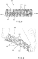
- a graft containment device 200 may be substantially similar to the device 100, as described above, comprising a body 202 formed via one or more helical structures 210 extending from a first end 204 to a second end 206 to define a channel 208 extending longitudinally therethrough.
- the body 202 may be substantially similar to the body 102 described above with respect to the device 100.
- the graft containment device 200 may include a plurality of buttons 220, each button 220 connecting adjacent turns of the one or more helical structures 210.
- buttons 220 may includes an opening 222 extending therethrough for receiving a shaft of a bone fixation element such as, for example, a bone screw, so that a fixation plate or other attachment may be fixed to the graft containment device 200.
- a bone fixation element such as, for example, a bone screw
- Each of the plurality of buttons 120 may be separated from one another along a length of the body 202.
- the buttons 220 may be alternatingly positioned between adjacent turns of the helical structures 210.
- the graft containment device 200 may include any number of buttons 220, each of the buttons 220 spaced from one another at any desired distance along a length of the body 202. The spacing between adjacent buttons 220 permits the graft containment device 200 to be expanded (as shown in Fig.
- the graft containment device 200 may be used in a manner substantially similar to the device 100, as described above.
- a graft containment device according to the present invention may, alternatively, comprise helical structures extending about a longitudinal axis thereof in opposing directions.
- a first helical structure may extend about the longitudinal axis in a first direction while a second helical structure may extend about the longitudinal axis in a second direction opposite the first direction.
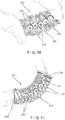
- a graft containment device 300 may be substantially similar to the devices 100, 200 described above, comprising a body 302 formed via helical structures 310 extending from a first end 304 to a second end 306 to define a channel 308.
- a first helical structure 310a extends about a longitudinal axis of the body 302 in a first direction while a second helical structure 310b extends about the longitudinal axis in a second direction opposite the first direction B i.e., the angles of the helices of the first and second structures 310, 320 are inclined to form a V-like shape where they cross.
- first ends 304 of the helical structures 310 may be connected to one another via a first connecting structure 316, which may be configured as, for example, a ring.
- Second ends 306 of the helical structures 310 may be connected to one another via a second connecting structure 318, which may be configured as, for example, a ring.
- the graft containment device 300 is shown and described as being comprised of two helical structures 310, it will be understood by those of skill in the art that the graft containment device 300 may include more than two helical structures 310, if so desired, so long as at least two of the helical structures 310 along the length of the body 302 in opposing directions.
- the multiple helical structures 310 extend freely so that the helical structures 310 are not connected to one another except via the first and second connecting structures 316, 318 at the first and second ends 304, 306, respectively.
- the helical structures 310 may be connected to one another at one or more points 314 where the first and second helical structures 310a, 310b cross one another.
- the helical structures 310 may be connected at every crossing point 314 or, alternatively, may be connected at specific crossing points 314, as desired.
- the graft containment device 300 may also include structures or features for receiving fixation elements such as, for example, the longitudinal struts 120 described above in regard to the device 100 or the buttons 220 described above in regard to the device 200.
- the buttons 220 may act as a connection at crossing points 314.
- a device 400 may be substantially similar to the devices 100 - 300 described above, comprising a body 404 formed via a helical structure 410 extending from a first end 404 to a second end 406 to define a channel 408.
- the helical structure 410 may include portions which have a wave configuration 411.
- the wave configuration 411 may extend along portions of the helical structure 410 along one side of the body 402. Alternatively, the wave configuration 411 may extend along the entire helical structure 410.
- the wave configuration 411 may provide greater retention for graft material received within the channel 408.
- the wave configuration 411 may interlock with one another when the graft containment device 400 is compressed, providing rigidity to the graft containment device 400.
- the helical structure 410 is configured so that, even when portions of the wave configuration are interlocked, graft material may be packed into the channel 408 via a space 412 between adjacent turns of the helical structure 410 by moving the adjacent turns away from one another to increase the space 412 therebetween.
Landscapes
- Health & Medical Sciences (AREA)
- Transplantation (AREA)
- Orthopedic Medicine & Surgery (AREA)
- Cardiology (AREA)
- Oral & Maxillofacial Surgery (AREA)
- Engineering & Computer Science (AREA)
- Biomedical Technology (AREA)
- Heart & Thoracic Surgery (AREA)
- Vascular Medicine (AREA)
- Life Sciences & Earth Sciences (AREA)
- Animal Behavior & Ethology (AREA)
- General Health & Medical Sciences (AREA)
- Public Health (AREA)
- Veterinary Medicine (AREA)
- Plastic & Reconstructive Surgery (AREA)
- Prostheses (AREA)
Applications Claiming Priority (2)
| Application Number | Priority Date | Filing Date | Title |
|---|---|---|---|
| US201662288273P | 2016-01-28 | 2016-01-28 | |
| PCT/US2017/014029 WO2017132039A1 (en) | 2016-01-28 | 2017-01-19 | Helical bone graft containment cage |
Publications (2)
| Publication Number | Publication Date |
|---|---|
| EP3407837A1 EP3407837A1 (en) | 2018-12-05 |
| EP3407837B1 true EP3407837B1 (en) | 2021-07-07 |
Family
ID=57995273
Family Applications (1)
| Application Number | Title | Priority Date | Filing Date |
|---|---|---|---|
| EP17704122.5A Active EP3407837B1 (en) | 2016-01-28 | 2017-01-19 | Helical bone graft containment cage |
Country Status (8)
| Country | Link |
|---|---|
| US (1) | US11478356B2 (enExample) |
| EP (1) | EP3407837B1 (enExample) |
| JP (1) | JP6976956B2 (enExample) |
| CN (1) | CN108601658A (enExample) |
| AU (1) | AU2017211022B2 (enExample) |
| BR (1) | BR112018014553A2 (enExample) |
| CA (1) | CA3012442A1 (enExample) |
| WO (1) | WO2017132039A1 (enExample) |
Families Citing this family (23)
| Publication number | Priority date | Publication date | Assignee | Title |
|---|---|---|---|---|
| EP3288501B1 (en) | 2015-04-29 | 2020-11-25 | Institute For Musculoskeletal Science And Education, Ltd. | Coiled implants |
| US10449051B2 (en) | 2015-04-29 | 2019-10-22 | Institute for Musculoskeletal Science and Education, Ltd. | Implant with curved bone contacting elements |
| US10709570B2 (en) | 2015-04-29 | 2020-07-14 | Institute for Musculoskeletal Science and Education, Ltd. | Implant with a diagonal insertion axis |
| US10492921B2 (en) | 2015-04-29 | 2019-12-03 | Institute for Musculoskeletal Science and Education, Ltd. | Implant with arched bone contacting elements |
| DE102015106861B4 (de) | 2015-05-04 | 2025-04-30 | Espera-Werke Gmbh | Vorrichtung zum Etikettieren von einzelnen Produkten |
| US11207185B2 (en) * | 2016-01-28 | 2021-12-28 | DePuy Synthes Products, Inc. | Splitting attachment for graft containment cage |
| US10478312B2 (en) | 2016-10-25 | 2019-11-19 | Institute for Musculoskeletal Science and Education, Ltd. | Implant with protected fusion zones |
| US11033394B2 (en) | 2016-10-25 | 2021-06-15 | Institute for Musculoskeletal Science and Education, Ltd. | Implant with multi-layer bone interfacing lattice |
| US10357377B2 (en) | 2017-03-13 | 2019-07-23 | Institute for Musculoskeletal Science and Education, Ltd. | Implant with bone contacting elements having helical and undulating planar geometries |
| US10512549B2 (en) * | 2017-03-13 | 2019-12-24 | Institute for Musculoskeletal Science and Education, Ltd. | Implant with structural members arranged around a ring |
| US10932912B2 (en) | 2017-09-11 | 2021-03-02 | DePuy Synthes Products, Inc. | Plug in struts for graft cage |
| US10357367B2 (en) * | 2017-09-11 | 2019-07-23 | DePuy Synthes Products, Inc. | Patient-specific mandible graft cage |
| US10744001B2 (en) | 2017-11-21 | 2020-08-18 | Institute for Musculoskeletal Science and Education, Ltd. | Implant with improved bone contact |
| US10940015B2 (en) | 2017-11-21 | 2021-03-09 | Institute for Musculoskeletal Science and Education, Ltd. | Implant with improved flow characteristics |
| CN109492887B (zh) * | 2018-10-25 | 2021-10-26 | 浙江工商大学 | 基于势博弈理论的移动群智感知激励方法 |
| KR101996849B1 (ko) * | 2018-12-26 | 2019-10-01 | (주)메디쎄이 | 하악골결손부위에 삽입되는 환자 맞춤형 하악골 임플란트 및 이의 제조방법 |
| TWI716156B (zh) * | 2019-10-18 | 2021-01-11 | 財團法人工業技術研究院 | 口顎重建彌補物 |
| US11504240B2 (en) | 2020-06-04 | 2022-11-22 | DePuy Synthes Products, Inc. | Modular bone graft cage |
| CN117136082A (zh) * | 2021-03-26 | 2023-11-28 | 因纳瓦斯克医疗股份有限公司 | 血管动静脉移植物 |
| WO2022241051A1 (en) * | 2021-05-13 | 2022-11-17 | Toranto Jason D | Mandibular reconstruction systems and methods |
| US12064156B2 (en) | 2023-01-09 | 2024-08-20 | John F. Krumme | Dynamic compression fixation devices |
| US12295849B2 (en) | 2023-01-26 | 2025-05-13 | Jason D. Toranto | Mandibular reconstruction systems and methods |
| CN116747051B (zh) * | 2023-08-22 | 2023-11-24 | 北京大学第三医院(北京大学第三临床医学院) | 一种骨植入物 |
Family Cites Families (23)
| Publication number | Priority date | Publication date | Assignee | Title |
|---|---|---|---|---|
| US4787906A (en) * | 1987-03-02 | 1988-11-29 | Haris Andras G | Controlled tissue growth and graft containment |
| US6989033B1 (en) * | 1992-09-17 | 2006-01-24 | Karlheinz Schmidt | Implant for recreating verterbrae and tubular bones |
| DE4409836A1 (de) * | 1994-03-22 | 1995-09-28 | Draenert Klaus | Vorrichtung zum mechanischen Schutz eines Implantats oder Transplantats beim Einführen in einen und/oder Verbleiben in einem lebenden Körper |
| US6280473B1 (en) * | 1996-08-19 | 2001-08-28 | Macropore, Inc. | Resorbable, macro-porous, non-collapsing and flexible membrane barrier for skeletal repair and regeneration |
| US6149651A (en) * | 1997-06-02 | 2000-11-21 | Sdgi Holdings, Inc. | Device for supporting weak bony structures |
| US7553329B2 (en) * | 1999-08-18 | 2009-06-30 | Intrinsic Therapeutics, Inc. | Stabilized intervertebral disc barrier |
| US6447543B1 (en) * | 1999-09-28 | 2002-09-10 | Sulzer Orthopedics Ltd. | Basket-like container for implanting bone tissue |
| JP2003165761A (ja) * | 2001-11-29 | 2003-06-10 | Kinki Concrete Industry Co Ltd | 屋根土組成物 |
| US7887587B2 (en) * | 2004-06-04 | 2011-02-15 | Synthes Usa, Llc | Soft tissue spacer |
| EP3451298A3 (en) * | 2011-12-14 | 2019-06-05 | Stryker European Holdings I, LLC | Technique for generating a bone plate design |
| US8485820B1 (en) * | 2011-12-22 | 2013-07-16 | Mohamed Ikbal Ali | Devices and methods for enhancing bone growth |
| JP6062150B2 (ja) * | 2012-02-14 | 2017-01-18 | 株式会社ハイレックスコーポレーション | 骨欠損部充填材料 |
| TW201240653A (en) * | 2012-05-30 | 2012-10-16 | Ossaware Biotech Co Ltd | Hollow-grid medical implant |
| US9936991B2 (en) * | 2015-01-30 | 2018-04-10 | Union Surgical, Llc | Bone fracture treatment apparatus and method |
| US9706294B2 (en) * | 2015-03-18 | 2017-07-11 | Infineon Technologies Ag | System and method for an acoustic transducer and environmental sensor package |
| US9925046B2 (en) * | 2015-03-31 | 2018-03-27 | DePuy Synthes Products, Inc. | Bone graft cage |
| EP3288501B1 (en) * | 2015-04-29 | 2020-11-25 | Institute For Musculoskeletal Science And Education, Ltd. | Coiled implants |
| GB201609448D0 (en) | 2015-09-10 | 2016-07-13 | Obl S A | Medical device |
| DE102015226063A1 (de) * | 2015-12-18 | 2017-06-22 | Aesculap Ag | Medizinisches Produkt sowie medizinisches Kit zur Anwendung bei der Behandlung, insbesondere zur Anwendung beim Auffüllen und/oder Verschluss, einer Knochenkavität |
| US10695181B2 (en) * | 2016-02-16 | 2020-06-30 | DePuy Synthes Products, Inc. | Bone graft cage |
| CA3052282A1 (en) * | 2017-02-06 | 2018-08-09 | DePuy Synthes Products, Inc. | Bendable graft containment cage |
| US10357367B2 (en) * | 2017-09-11 | 2019-07-23 | DePuy Synthes Products, Inc. | Patient-specific mandible graft cage |
| US10932912B2 (en) * | 2017-09-11 | 2021-03-02 | DePuy Synthes Products, Inc. | Plug in struts for graft cage |
-
2017
- 2017-01-19 CA CA3012442A patent/CA3012442A1/en active Pending
- 2017-01-19 CN CN201780008874.3A patent/CN108601658A/zh active Pending
- 2017-01-19 JP JP2018539272A patent/JP6976956B2/ja active Active
- 2017-01-19 WO PCT/US2017/014029 patent/WO2017132039A1/en not_active Ceased
- 2017-01-19 BR BR112018014553A patent/BR112018014553A2/pt active Search and Examination
- 2017-01-19 AU AU2017211022A patent/AU2017211022B2/en not_active Ceased
- 2017-01-19 EP EP17704122.5A patent/EP3407837B1/en active Active
- 2017-01-20 US US15/411,499 patent/US11478356B2/en active Active
Non-Patent Citations (1)
| Title |
|---|
| None * |
Also Published As
| Publication number | Publication date |
|---|---|
| BR112018014553A2 (pt) | 2018-12-11 |
| AU2017211022A1 (en) | 2018-06-28 |
| JP6976956B2 (ja) | 2021-12-08 |
| CN108601658A (zh) | 2018-09-28 |
| WO2017132039A1 (en) | 2017-08-03 |
| EP3407837A1 (en) | 2018-12-05 |
| US20170216034A1 (en) | 2017-08-03 |
| AU2017211022B2 (en) | 2021-05-20 |
| JP2019503248A (ja) | 2019-02-07 |
| US11478356B2 (en) | 2022-10-25 |
| CA3012442A1 (en) | 2017-08-03 |
Similar Documents
| Publication | Publication Date | Title |
|---|---|---|
| EP3407837B1 (en) | Helical bone graft containment cage | |
| US11213395B2 (en) | Bendable graft containment cage | |
| EP3160372B1 (en) | Locking first metacarpal plate | |
| CA2781118C (en) | Flexible maxillo-mandibular fixation device | |
| CN106488750B (zh) | 掌骨颈部板 | |
| CN108601659B (zh) | 用于移植物容纳保持架的分裂附接件 | |
| US11633284B2 (en) | Fold-up containment device for bone defects | |
| US20210145587A1 (en) | Plug in struts for graft cage | |
| JP6852201B2 (ja) | 係止式ウェブプレート | |
| CN106659526A (zh) | 可变角锁定旋转矫正板 | |
| KR101973812B1 (ko) | 쇄골 골수강내 고정막대 |
Legal Events
| Date | Code | Title | Description |
|---|---|---|---|
| STAA | Information on the status of an ep patent application or granted ep patent |
Free format text: STATUS: UNKNOWN |
|
| STAA | Information on the status of an ep patent application or granted ep patent |
Free format text: STATUS: THE INTERNATIONAL PUBLICATION HAS BEEN MADE |
|
| PUAI | Public reference made under article 153(3) epc to a published international application that has entered the european phase |
Free format text: ORIGINAL CODE: 0009012 |
|
| STAA | Information on the status of an ep patent application or granted ep patent |
Free format text: STATUS: REQUEST FOR EXAMINATION WAS MADE |
|
| 17P | Request for examination filed |
Effective date: 20180814 |
|
| AK | Designated contracting states |
Kind code of ref document: A1 Designated state(s): AL AT BE BG CH CY CZ DE DK EE ES FI FR GB GR HR HU IE IS IT LI LT LU LV MC MK MT NL NO PL PT RO RS SE SI SK SM TR |
|
| AX | Request for extension of the european patent |
Extension state: BA ME |
|
| DAV | Request for validation of the european patent (deleted) | ||
| DAX | Request for extension of the european patent (deleted) | ||
| STAA | Information on the status of an ep patent application or granted ep patent |
Free format text: STATUS: EXAMINATION IS IN PROGRESS |
|
| 17Q | First examination report despatched |
Effective date: 20191028 |
|
| GRAJ | Information related to disapproval of communication of intention to grant by the applicant or resumption of examination proceedings by the epo deleted |
Free format text: ORIGINAL CODE: EPIDOSDIGR1 |
|
| GRAP | Despatch of communication of intention to grant a patent |
Free format text: ORIGINAL CODE: EPIDOSNIGR1 |
|
| STAA | Information on the status of an ep patent application or granted ep patent |
Free format text: STATUS: GRANT OF PATENT IS INTENDED |
|
| GRAJ | Information related to disapproval of communication of intention to grant by the applicant or resumption of examination proceedings by the epo deleted |
Free format text: ORIGINAL CODE: EPIDOSDIGR1 |
|
| GRAP | Despatch of communication of intention to grant a patent |
Free format text: ORIGINAL CODE: EPIDOSNIGR1 |
|
| STAA | Information on the status of an ep patent application or granted ep patent |
Free format text: STATUS: EXAMINATION IS IN PROGRESS |
|
| RIN1 | Information on inventor provided before grant (corrected) |
Inventor name: DANIEL, STEFFAN Inventor name: FURRER, ANDRE Inventor name: LARSEN, SCOTT |
|
| GRAP | Despatch of communication of intention to grant a patent |
Free format text: ORIGINAL CODE: EPIDOSNIGR1 |
|
| STAA | Information on the status of an ep patent application or granted ep patent |
Free format text: STATUS: GRANT OF PATENT IS INTENDED |
|
| INTG | Intention to grant announced |
Effective date: 20210119 |
|
| INTG | Intention to grant announced |
Effective date: 20210128 |
|
| GRAS | Grant fee paid |
Free format text: ORIGINAL CODE: EPIDOSNIGR3 |
|
| GRAA | (expected) grant |
Free format text: ORIGINAL CODE: 0009210 |
|
| STAA | Information on the status of an ep patent application or granted ep patent |
Free format text: STATUS: THE PATENT HAS BEEN GRANTED |
|
| AK | Designated contracting states |
Kind code of ref document: B1 Designated state(s): AL AT BE BG CH CY CZ DE DK EE ES FI FR GB GR HR HU IE IS IT LI LT LU LV MC MK MT NL NO PL PT RO RS SE SI SK SM TR |
|
| REG | Reference to a national code |
Ref country code: GB Ref legal event code: FG4D |
|
| REG | Reference to a national code |
Ref country code: AT Ref legal event code: REF Ref document number: 1407841 Country of ref document: AT Kind code of ref document: T Effective date: 20210715 |
|
| REG | Reference to a national code |
Ref country code: DE Ref legal event code: R096 Ref document number: 602017041582 Country of ref document: DE |
|
| REG | Reference to a national code |
Ref country code: IE Ref legal event code: FG4D |
|
| REG | Reference to a national code |
Ref country code: LT Ref legal event code: MG9D |
|
| REG | Reference to a national code |
Ref country code: NL Ref legal event code: MP Effective date: 20210707 |
|
| REG | Reference to a national code |
Ref country code: AT Ref legal event code: MK05 Ref document number: 1407841 Country of ref document: AT Kind code of ref document: T Effective date: 20210707 |
|
| PG25 | Lapsed in a contracting state [announced via postgrant information from national office to epo] |
Ref country code: PT Free format text: LAPSE BECAUSE OF FAILURE TO SUBMIT A TRANSLATION OF THE DESCRIPTION OR TO PAY THE FEE WITHIN THE PRESCRIBED TIME-LIMIT Effective date: 20211108 Ref country code: NO Free format text: LAPSE BECAUSE OF FAILURE TO SUBMIT A TRANSLATION OF THE DESCRIPTION OR TO PAY THE FEE WITHIN THE PRESCRIBED TIME-LIMIT Effective date: 20211007 Ref country code: NL Free format text: LAPSE BECAUSE OF FAILURE TO SUBMIT A TRANSLATION OF THE DESCRIPTION OR TO PAY THE FEE WITHIN THE PRESCRIBED TIME-LIMIT Effective date: 20210707 Ref country code: ES Free format text: LAPSE BECAUSE OF FAILURE TO SUBMIT A TRANSLATION OF THE DESCRIPTION OR TO PAY THE FEE WITHIN THE PRESCRIBED TIME-LIMIT Effective date: 20210707 Ref country code: FI Free format text: LAPSE BECAUSE OF FAILURE TO SUBMIT A TRANSLATION OF THE DESCRIPTION OR TO PAY THE FEE WITHIN THE PRESCRIBED TIME-LIMIT Effective date: 20210707 Ref country code: AT Free format text: LAPSE BECAUSE OF FAILURE TO SUBMIT A TRANSLATION OF THE DESCRIPTION OR TO PAY THE FEE WITHIN THE PRESCRIBED TIME-LIMIT Effective date: 20210707 Ref country code: BG Free format text: LAPSE BECAUSE OF FAILURE TO SUBMIT A TRANSLATION OF THE DESCRIPTION OR TO PAY THE FEE WITHIN THE PRESCRIBED TIME-LIMIT Effective date: 20211007 Ref country code: LT Free format text: LAPSE BECAUSE OF FAILURE TO SUBMIT A TRANSLATION OF THE DESCRIPTION OR TO PAY THE FEE WITHIN THE PRESCRIBED TIME-LIMIT Effective date: 20210707 Ref country code: RS Free format text: LAPSE BECAUSE OF FAILURE TO SUBMIT A TRANSLATION OF THE DESCRIPTION OR TO PAY THE FEE WITHIN THE PRESCRIBED TIME-LIMIT Effective date: 20210707 Ref country code: SE Free format text: LAPSE BECAUSE OF FAILURE TO SUBMIT A TRANSLATION OF THE DESCRIPTION OR TO PAY THE FEE WITHIN THE PRESCRIBED TIME-LIMIT Effective date: 20210707 Ref country code: HR Free format text: LAPSE BECAUSE OF FAILURE TO SUBMIT A TRANSLATION OF THE DESCRIPTION OR TO PAY THE FEE WITHIN THE PRESCRIBED TIME-LIMIT Effective date: 20210707 |
|
| PGFP | Annual fee paid to national office [announced via postgrant information from national office to epo] |
Ref country code: GB Payment date: 20211206 Year of fee payment: 6 Ref country code: FR Payment date: 20211214 Year of fee payment: 6 |
|
| PG25 | Lapsed in a contracting state [announced via postgrant information from national office to epo] |
Ref country code: PL Free format text: LAPSE BECAUSE OF FAILURE TO SUBMIT A TRANSLATION OF THE DESCRIPTION OR TO PAY THE FEE WITHIN THE PRESCRIBED TIME-LIMIT Effective date: 20210707 Ref country code: LV Free format text: LAPSE BECAUSE OF FAILURE TO SUBMIT A TRANSLATION OF THE DESCRIPTION OR TO PAY THE FEE WITHIN THE PRESCRIBED TIME-LIMIT Effective date: 20210707 Ref country code: GR Free format text: LAPSE BECAUSE OF FAILURE TO SUBMIT A TRANSLATION OF THE DESCRIPTION OR TO PAY THE FEE WITHIN THE PRESCRIBED TIME-LIMIT Effective date: 20211008 |
|
| PGFP | Annual fee paid to national office [announced via postgrant information from national office to epo] |
Ref country code: CH Payment date: 20211216 Year of fee payment: 6 |
|
| REG | Reference to a national code |
Ref country code: DE Ref legal event code: R097 Ref document number: 602017041582 Country of ref document: DE |
|
| PG25 | Lapsed in a contracting state [announced via postgrant information from national office to epo] |
Ref country code: DK Free format text: LAPSE BECAUSE OF FAILURE TO SUBMIT A TRANSLATION OF THE DESCRIPTION OR TO PAY THE FEE WITHIN THE PRESCRIBED TIME-LIMIT Effective date: 20210707 |
|
| PGFP | Annual fee paid to national office [announced via postgrant information from national office to epo] |
Ref country code: DE Payment date: 20211130 Year of fee payment: 6 |
|
| PLBE | No opposition filed within time limit |
Free format text: ORIGINAL CODE: 0009261 |
|
| STAA | Information on the status of an ep patent application or granted ep patent |
Free format text: STATUS: NO OPPOSITION FILED WITHIN TIME LIMIT |
|
| PG25 | Lapsed in a contracting state [announced via postgrant information from national office to epo] |
Ref country code: SM Free format text: LAPSE BECAUSE OF FAILURE TO SUBMIT A TRANSLATION OF THE DESCRIPTION OR TO PAY THE FEE WITHIN THE PRESCRIBED TIME-LIMIT Effective date: 20210707 Ref country code: SK Free format text: LAPSE BECAUSE OF FAILURE TO SUBMIT A TRANSLATION OF THE DESCRIPTION OR TO PAY THE FEE WITHIN THE PRESCRIBED TIME-LIMIT Effective date: 20210707 Ref country code: RO Free format text: LAPSE BECAUSE OF FAILURE TO SUBMIT A TRANSLATION OF THE DESCRIPTION OR TO PAY THE FEE WITHIN THE PRESCRIBED TIME-LIMIT Effective date: 20210707 Ref country code: EE Free format text: LAPSE BECAUSE OF FAILURE TO SUBMIT A TRANSLATION OF THE DESCRIPTION OR TO PAY THE FEE WITHIN THE PRESCRIBED TIME-LIMIT Effective date: 20210707 Ref country code: CZ Free format text: LAPSE BECAUSE OF FAILURE TO SUBMIT A TRANSLATION OF THE DESCRIPTION OR TO PAY THE FEE WITHIN THE PRESCRIBED TIME-LIMIT Effective date: 20210707 Ref country code: AL Free format text: LAPSE BECAUSE OF FAILURE TO SUBMIT A TRANSLATION OF THE DESCRIPTION OR TO PAY THE FEE WITHIN THE PRESCRIBED TIME-LIMIT Effective date: 20210707 |
|
| PGFP | Annual fee paid to national office [announced via postgrant information from national office to epo] |
Ref country code: IT Payment date: 20211213 Year of fee payment: 6 |
|
| 26N | No opposition filed |
Effective date: 20220408 |
|
| PG25 | Lapsed in a contracting state [announced via postgrant information from national office to epo] |
Ref country code: MC Free format text: LAPSE BECAUSE OF FAILURE TO SUBMIT A TRANSLATION OF THE DESCRIPTION OR TO PAY THE FEE WITHIN THE PRESCRIBED TIME-LIMIT Effective date: 20210707 |
|
| REG | Reference to a national code |
Ref country code: BE Ref legal event code: MM Effective date: 20220131 |
|
| PG25 | Lapsed in a contracting state [announced via postgrant information from national office to epo] |
Ref country code: LU Free format text: LAPSE BECAUSE OF NON-PAYMENT OF DUE FEES Effective date: 20220119 |
|
| PG25 | Lapsed in a contracting state [announced via postgrant information from national office to epo] |
Ref country code: BE Free format text: LAPSE BECAUSE OF NON-PAYMENT OF DUE FEES Effective date: 20220131 |
|
| PG25 | Lapsed in a contracting state [announced via postgrant information from national office to epo] |
Ref country code: IE Free format text: LAPSE BECAUSE OF NON-PAYMENT OF DUE FEES Effective date: 20220119 |
|
| REG | Reference to a national code |
Ref country code: DE Ref legal event code: R119 Ref document number: 602017041582 Country of ref document: DE |
|
| REG | Reference to a national code |
Ref country code: CH Ref legal event code: PL |
|
| GBPC | Gb: european patent ceased through non-payment of renewal fee |
Effective date: 20230119 |
|
| PG25 | Lapsed in a contracting state [announced via postgrant information from national office to epo] |
Ref country code: LI Free format text: LAPSE BECAUSE OF NON-PAYMENT OF DUE FEES Effective date: 20230131 Ref country code: GB Free format text: LAPSE BECAUSE OF NON-PAYMENT OF DUE FEES Effective date: 20230119 Ref country code: DE Free format text: LAPSE BECAUSE OF NON-PAYMENT OF DUE FEES Effective date: 20230801 Ref country code: CH Free format text: LAPSE BECAUSE OF NON-PAYMENT OF DUE FEES Effective date: 20230131 |
|
| PG25 | Lapsed in a contracting state [announced via postgrant information from national office to epo] |
Ref country code: FR Free format text: LAPSE BECAUSE OF NON-PAYMENT OF DUE FEES Effective date: 20230131 |
|
| PG25 | Lapsed in a contracting state [announced via postgrant information from national office to epo] |
Ref country code: IT Free format text: LAPSE BECAUSE OF NON-PAYMENT OF DUE FEES Effective date: 20230119 |
|
| PG25 | Lapsed in a contracting state [announced via postgrant information from national office to epo] |
Ref country code: HU Free format text: LAPSE BECAUSE OF FAILURE TO SUBMIT A TRANSLATION OF THE DESCRIPTION OR TO PAY THE FEE WITHIN THE PRESCRIBED TIME-LIMIT; INVALID AB INITIO Effective date: 20170119 |
|
| PG25 | Lapsed in a contracting state [announced via postgrant information from national office to epo] |
Ref country code: MK Free format text: LAPSE BECAUSE OF FAILURE TO SUBMIT A TRANSLATION OF THE DESCRIPTION OR TO PAY THE FEE WITHIN THE PRESCRIBED TIME-LIMIT Effective date: 20210707 Ref country code: CY Free format text: LAPSE BECAUSE OF FAILURE TO SUBMIT A TRANSLATION OF THE DESCRIPTION OR TO PAY THE FEE WITHIN THE PRESCRIBED TIME-LIMIT Effective date: 20210707 |
|
| PG25 | Lapsed in a contracting state [announced via postgrant information from national office to epo] |
Ref country code: MT Free format text: LAPSE BECAUSE OF FAILURE TO SUBMIT A TRANSLATION OF THE DESCRIPTION OR TO PAY THE FEE WITHIN THE PRESCRIBED TIME-LIMIT Effective date: 20210707 |
|
| PG25 | Lapsed in a contracting state [announced via postgrant information from national office to epo] |
Ref country code: TR Free format text: LAPSE BECAUSE OF FAILURE TO SUBMIT A TRANSLATION OF THE DESCRIPTION OR TO PAY THE FEE WITHIN THE PRESCRIBED TIME-LIMIT Effective date: 20210707 |