EP3407629B1 - Hearing aid device unit along a single curved axis - Google Patents
Hearing aid device unit along a single curved axis Download PDFInfo
- Publication number
- EP3407629B1 EP3407629B1 EP18173564.8A EP18173564A EP3407629B1 EP 3407629 B1 EP3407629 B1 EP 3407629B1 EP 18173564 A EP18173564 A EP 18173564A EP 3407629 B1 EP3407629 B1 EP 3407629B1
- Authority
- EP
- European Patent Office
- Prior art keywords
- housing
- hearing aid
- microphone
- inlet
- aid unit
- Prior art date
- Legal status (The legal status is an assumption and is not a legal conclusion. Google has not performed a legal analysis and makes no representation as to the accuracy of the status listed.)
- Active
Links
Images


Classifications
-
- H—ELECTRICITY
- H04—ELECTRIC COMMUNICATION TECHNIQUE
- H04R—LOUDSPEAKERS, MICROPHONES, GRAMOPHONE PICK-UPS OR LIKE ACOUSTIC ELECTROMECHANICAL TRANSDUCERS; DEAF-AID SETS; PUBLIC ADDRESS SYSTEMS
- H04R25/00—Deaf-aid sets, i.e. electro-acoustic or electro-mechanical hearing aids; Electric tinnitus maskers providing an auditory perception
- H04R25/65—Housing parts, e.g. shells, tips or moulds, or their manufacture
-
- H—ELECTRICITY
- H04—ELECTRIC COMMUNICATION TECHNIQUE
- H04R—LOUDSPEAKERS, MICROPHONES, GRAMOPHONE PICK-UPS OR LIKE ACOUSTIC ELECTROMECHANICAL TRANSDUCERS; DEAF-AID SETS; PUBLIC ADDRESS SYSTEMS
- H04R25/00—Deaf-aid sets, i.e. electro-acoustic or electro-mechanical hearing aids; Electric tinnitus maskers providing an auditory perception
- H04R25/02—Deaf-aid sets, i.e. electro-acoustic or electro-mechanical hearing aids; Electric tinnitus maskers providing an auditory perception adapted to be supported entirely by ear
-
- H—ELECTRICITY
- H04—ELECTRIC COMMUNICATION TECHNIQUE
- H04R—LOUDSPEAKERS, MICROPHONES, GRAMOPHONE PICK-UPS OR LIKE ACOUSTIC ELECTROMECHANICAL TRANSDUCERS; DEAF-AID SETS; PUBLIC ADDRESS SYSTEMS
- H04R2225/00—Details of deaf aids covered by H04R25/00, not provided for in any of its subgroups
- H04R2225/021—Behind the ear [BTE] hearing aids
- H04R2225/0213—Constructional details of earhooks, e.g. shape, material
-
- H—ELECTRICITY
- H04—ELECTRIC COMMUNICATION TECHNIQUE
- H04R—LOUDSPEAKERS, MICROPHONES, GRAMOPHONE PICK-UPS OR LIKE ACOUSTIC ELECTROMECHANICAL TRANSDUCERS; DEAF-AID SETS; PUBLIC ADDRESS SYSTEMS
- H04R2225/00—Details of deaf aids covered by H04R25/00, not provided for in any of its subgroups
- H04R2225/021—Behind the ear [BTE] hearing aids
- H04R2225/0216—BTE hearing aids having a receiver in the ear mould
-
- H—ELECTRICITY
- H04—ELECTRIC COMMUNICATION TECHNIQUE
- H04R—LOUDSPEAKERS, MICROPHONES, GRAMOPHONE PICK-UPS OR LIKE ACOUSTIC ELECTROMECHANICAL TRANSDUCERS; DEAF-AID SETS; PUBLIC ADDRESS SYSTEMS
- H04R25/00—Deaf-aid sets, i.e. electro-acoustic or electro-mechanical hearing aids; Electric tinnitus maskers providing an auditory perception
- H04R25/60—Mounting or interconnection of hearing aid parts, e.g. inside tips, housings or to ossicles
- H04R25/607—Mounting or interconnection of hearing aid parts, e.g. inside tips, housings or to ossicles of earhooks
Definitions
- the disclosure relates to a hearing aid.
- the disclosure relates to a behind-the-ear (BTE) hearing aid unit, which may be a sound processor for a cochlear implant.
- BTE hearing aid unit includes a housing comprising a hollow inner section extending completely along a single curved axis and made of a single inseparable unit.
- a hearing aid is a device for aiding an individual in regard to his or her hearing. It is generally used to compensate a hearing loss, namely a conventional acoustic hearing aid amplifying sound, or a cochlear implant that electrically stimulates nerve cells or a bone conduction hearing aid. It may also be a hearing protection device which helps individuals to hear without damage in noisy environments. It may also be a tinnitus treatment device.
- BTE hearing aid units such as traditional BTE hearing aids comprise a partially longitudinal, hook-shaped shell running substantially along a longitudinal axis and containing electronic components within the shell.
- One shell end usually the tapering end, constitutes the ear hook that is used to rest the hearing aid unit on and behind a user's ear.
- the shell is made of two lengthwise parts that are joined together to form the shell. The electronic components are placed on top of inner surface of one of the parts before the two parts are joined together. This type of shell suffers from a number of drawbacks:
- the disclosure proposes a solution that overcomes the aforementioned drawbacks.
- a behind-the-ear (BTE) hearing aid unit includes a housing comprising a hollow inner section defined by an enclosed wall surface made of a single inseparable unit, an electronic module, and an ear hook that is permanently or detachably attached to the housing.
- the housing extends completely along a single curved axis running along the enclosed wall surface from a first end of the housing comprising the ear hook and a second end of the housing opposite to the ear hook.
- the housing comprises an inlet opening at the second end, wherein the inlet opening is adapted to receive the electronic module in the hollow inner section and the electronic module is adapted to move from the inlet opening along the single curved axis.
- the single inseparable unit is devoid of any parting lines or segments between enclosed wall surface that forms the hollow inner section.
- the hollow inner section defining a shell cannot be opened up in separate pieces, i.e. the housing is adapted to avoid being opened in separate pieces.
- This allows for avoiding access to the hollow inner section along the wall surface.
- the wall surface does not include any provision for providing access to the hollow inner section, the protection of the electronic module/ hollow inner section against dirt, sweat, humidity, water, etc. is significantly and mechanical strength of the hearing aid unit is increased. This may be particularly useful because the wall surface is typically exposed to and facing either user skin or environment during usage of a BTE hearing aid unit.
- the single curved axis may be defined by an arc such as a rotational axis.
- a center point around which the rotation axis is made may define the single curved axis.
- the arc may include i) a circular arc or a substantially circular arc. These arc may be understood as an arc of a segment of a circle or a substantial circular shape respectively, or ii) a parabolic arc, which may be understood as a segment of a parabolic arc.
- the curve axis is a rotational axis along which the electronic module is adapted to rotate during insertion of the electronic module into the hollow inner section.
- the rotational axis may be adapted to substantially match curvature of a depression behind outer ear next to the head, i.e. auricular sulcus of the user. In another embodiment, the rotational axis may be adapted to substantially match a curvature of depression behind outer ear next to the head, i.e. auricular sulcus of at least 50% of a sample population.
- the electronic module is fabricated on a chassis extending along a chassis axis that resembles the single curved axis.
- the term resembles indicate that the chassis axis and the single curved axis are at least substantially same.
- the electronic module allows the electronic module to move freely in a swift motion along the rotational axis within the hollow inner section from the inlet opening along the single curved axis during assembly. This is particularly useful in comparison to shells that include a combination of longitudinal axis and curved axis, where referred free movement of chassis is not possible, thus requiring a longer time and more complicated procedures during assembly. Additionally, the length of the electronic module may be matched with length of the hollow inner section, the length being along the single curved axis.
- the electronic module includes at least a processor, which is adapted to process an incoming signal that is used to compensate for the hearing loss of the user. Additionally, the electronic module may further include a microphone, which is adapted to receive a sound and generating the incoming signal that is provided to the processor. In one embodiment, the electronic module may include and electro-mechanical transducer such as a speaker. In another embodiment, the electronic module includes a memory and/ or a number of connectors for example, a connector for a cable of a cochlear implant connecting the BTE hearing aid unit (e.g. sound processor) to an antenna, and/ or multi-connector for connecting the processor with other devices like hearing aid programming system or a battery module or other attachment modules. In yet another embodiment, the electronic module may include power management unit including battery and connection between the battery and other electronic components such as processor. In other embodiments, electronic components like T-coil that are generally included in known hearing aid may also be included in the housing.
- a processor which is adapted to process an incoming signal that is used to compensate for the
- the second end may be understood as a base end of the BTE hearing aid unit, the base end being devoid of a connection to the ear hook.
- the BTE hearing aid unit includes a closing structure at the first end of the housing, the closing structure being part of the single inseparable unit.
- the closing structure is an integral part of the single inseparable unit without any parting lines either at the closing structure or at the interface between the closing structure and the enclosed wall surface. This allows for avoiding access to the hollow inner section from the closing structure or the interface and protecting of the electronic module/ hollow inner section against dirt, sweat, humidity, water, etc, and additionally also provides mechanical strength.
- the closing structure or ear hook comprises a protruded part and another of the closing structure or ear hook comprises a receiving section.
- the protruded part and the receiving section are configured to couple with each other such that the ear hook and the housing are immovable in lateral directions relative to each other.
- the lateral directions comprise direction sideways with respect to extrapolated axis, extending outwards from the first end, of the single curved axis.
- the protruded part and the receiving part includes threads that are adapted to cooperate with one to allow screwing of the ear hook to the housing.
- the coupling of the protruded part and the receiving section are configured to align a through-going hole of the ear hook and a through-going hole of the housing such that the aligned through-going holes are configured to receive an attachment unit that is adapted to immovably attach the detachably attached ear hook to the housing.
- the attachment unit such as a pin may be configured to go either partially or completely through combined width of the protruded part and the receiving section.
- a hearing aid includes a housing adapted to house the electronic module.
- the hearing aid housing further comprises an ear hook and a structure at the hook end of the housing.
- the structure and the ear hook includes features disclosed hereinabove with respect to the closing structure and ear hook respectively, i.e. structure or ear hook comprises a protruded part and another of the closing structure or ear hook comprises a receiving section, the protruded part and the receiving section being configured to couple with each other such that the ear hook and the housing are immovable in lateral directions relative to each other.
- the coupling of the protruded part and the receiving section is configured to align a through-going hole of the ear hook and a through-going hole of the housing such that the aligned through-going holes are configured to receive an attachment unit to immovably attach the detachably attached ear hook to the housing.
- the housing comprising a hollow inner section extending completely along a single curved axis and made of a single inseparable unit but in this embodiment, the housing may not necessarily include a single inseparable unit extending completely along a single curved axis.
- the BTE hearing aid unit includes a cover adapted to sealably close the hollow inner section at the second end, i.e. closing the inlet opening.
- the cover may be molded with the housing during the assembly.
- the cover includes a first set of connectors such as electrical slots and guide channels.
- the first set of connectors i) is adapted to establish electrical connection with the electronic module and ii) comprises one end that is accessible from outside the hollow inner section.
- the guide channel is configured to receive an attachable module comprising a second set of connectors such as electrical pins and an interacting means adapted to run along the guide channel to establish a mechanical connection between the housing and the attachable module and an electrical connection between the one end of the first set of connectors and second set of connectors.
- the BTE hearing aid unit and the attachable module may include an alignment structure in order to align the one end of the first set of connectors and second set of connectors.
- the BTE hearing aid unit and the attachable module are adapted to be locked using a locking mechanism.
- the attachable module may include a battery compartment, or fm receiver or programming interface or any other module that provides additional functionality to the hearing aid unit.
- the locking mechanism of the BTE hearing aid unit (first functional unit) and attachable module (second functional module) is disclosed in Figure 3 (locking mechanism comprising a moveable unit) and description of Figure 3 along with related text in the Summary section,
- Figure 4 (disclosing a friction element) and description of Figure 4 along with related text in the Summary section
- Figure 5 (disclosing a stop member) and description of Figure 5 along with related text in the Summary section of the pending EP16178631 .
- battery compartment as a detachable second functional unit is disclosed in Figures 1 and 2 and description of these figures along with related text in the Summary section of the pending EP application EP16178631 .
- EP16178631 is also relevant to the application. Such combination would allow for mechanically and electrically connecting the hearing aid unit with the attachment module in a secure manner and also for extending the functionalities of the hearing aid unit.
- the BTE hearing aid unit includes a microphone inlet cover adapted to attach to the housing to form a continuous concave shaped outer surface with the housing.
- the microphone inlet cover and the housing may include attachment means such as snap locking mechanism.
- the microphone inlet cover in cooperation with the housing exterior surface is adapted to form sound inlet channel adapted to allow ambient sound to travel from an entry of the sound inlet channel to an inlet port of a microphone that is comprised within the hollow inner section.
- the entry of the sound inlet channel is from side surface of the enclosed wall surface.
- the sound inlet channel may be adapted by varying dimensions of the sound inlet channel in order to avoid turbulent flow of air flowing at least in a part of the sound inlet channel.
- the sound inlet channel comprising a volumetric chamber at least directly above the microphone, preferably above the inlet.
- the dimensions of the volumetric chamber are adapted to bring pressure and/ or flow velocity of air flowing within the volumetric chamber substantially close to zero.
- the volumetric chamber is defined by a cut out section at the inner surface of the microphone inlet cover that is adapted to be at least directly above the microphone, preferably above the inlet.
- the cut out section in combination with the sound inlet channel that is at least directly above the microphone, preferably above the inlet forms a cross sectional area that is substantially larger than cross sectional area of rest of the sound inlet channel.
- the cross-sectional area refers to cross sectional area, as viewed from at least one a first direction and a second direction, the first direction and the second direction being orthogonal to each other. This allows for avoiding turbulent flow within the volumetric chamber and reducing the wind noise.
- dimensions of sound inlet channel the sound inlet channel is adapted to optimize wind noise suppression with respect to acoustic attenuation. Such optimization would result in an improved intelligibility of the signal.
- the dimensions may include length of the channel from the entry of the sound inlet channel to the inlet port and/ or cross-sectional dimensions of the sound inlet channel.
- the inlet channel includes capillary stop to minimize liquid ingress into microphones.
- the inlet channel includes a wall barrier comprising a height that is lower than height of the inlet channel at the location where the wall barrier is positioned.
- the wall barrier runs along a substantial length of the entry of the sound inlet channel, i.e. along the single curved axis.
- the wall barrier is typically positioned such that a distance between the wall barrier and the entry of the sound inlet channel inlet is smaller than the distance between the barrier wall and the inlet port of the microphone. The referred distance is measured along the channel path, i.e. the path that sound/ air follows to travel from the entry to inlet port of the microphone.
- the barrier wall allows for preventing ingress of moisture, grease, dirt, water, etc.
- the BTE hearing aid unit includes an alignment pin comprising a first end configured to be received within a receiving hole across the housing and comprised at a chassis holding the microphone, the chassis being positioned within the housing and the alignment pin being adapted to align the microphone with respect to an inlet and housing.
- the chassis may also provide a support for a circuit board to which the microphone is connected.
- the alignment pin is configured to go only in the receiving hole of the chassis, the chassis is positioned precisely in the housing and the microphone(s) are thus properly aligned with the inlet. This is particularly useful so that the liquid/ dust tight seal may be created between the inlet and housing.
- the alignment pin further includes a second end configured to be received within a recess at an inner surface of the microphone inlet cover.
- the alignment pin thus also adapted to provide an aligned position of the microphone inlet cover over the housing exterior surface, thereby creating desired inlet channels.
- the inner surface of the microphone inlet cover and the exterior surface of the housing cooperating with the microphone inlet cover are adapted to be concealed when the microphone inlet cover is in position.
- the alignment pin is typically positioned substantially perpendicular to the single curve axis.
- the BTE hearing aid unit includes an inlet aligned to the inlet port of the microphone.
- the inlet is attached to the housing with a sealing material interposed between the inlet and side surface of the housing.
- the sealing material provides a seal between the sound inlet channel and hollow inner shell.
- a hearing aid includes a housing adapted to house the electronic module.
- the hearing aid housing may further include an ear hook.
- the hearing aid includes a microphone inlet cover adapted to attach to the housing to form a continuous concave shaped outer surface with the housing, the microphone inlet cover in cooperation with the housing exterior surface is adapted to form sound inlet channel adapted to allow ambient sound to travel from an entry of the sound inlet channel to an inlet port of a microphone that is comprised within the hollow inner section.
- the hearing aid may include an alignment pin comprising a first end configured to be received within a receiving hole across the housing and comprised at a chassis holding the microphone, the chassis being positioned within the housing and the alignment pin being adapted to align the microphone with respect to an inlet and housing. Additionally, the alignment pin further includes a second end configured to be received within a recess at an inner surface of the microphone inlet cover. In an embodiment, the hearing aid also includes an inlet aligned to the inlet port of the microphone, the inlet being attached to the housing with a sealing material interposed between the inlet and side surface of the housing. The hearing aid may further include features relating to positioning of microphone inlet cover that are described above in earlier embodiments. In another embodiment, the hearing aid further includes the volumetric chamber as disclosed previously.
- the housing may not necessarily include a single inseparable unit extending completely along a single curved axis.
- the housing exterior surface comprises a push button slot comprising at least one slot to receive at least one push actuator and a fixing means slot.
- the fixing means slot extends beyond the curved concave exterior surface of the housing.
- the at least one push actuator is adapted to be fixedly positioned within the at least one slot with a sealing material interposed between the push actuator and side surface of the push button slot.
- the interposed sealing material is adapted to seal the hollow inner section against dirt, dust or sweat, etc.
- the BTE hearing aid unit includes a push button cover and a fixing means.
- the push button cover is adapted to cover the at least one push actuator.
- the fixing means is adapted to pass through the push button cover and to be received within the fixing means slot in order to attach the push button cover with the housing.
- the fixing means include a pin adapted to pass through the push button cover and the fixing means slot include adjacent walls positioned within the push button slot, the adjacent walls being configured to receive the pin and lock the pin by snapping length of the pin between the adjacent walls.
- the fixing means include a pin and the fixing means slot include a tunnel running, at least partially, across the push button slot.
- the push button cover includes holes on both sides of cover wall, wherein the holes are configured to align with the tunnel such that the pin is adapted to pass through the holes and tunnel in order to provide attachment between the push button cover and the housing.
- the push button may be programmed to perform different functions.
- the push button may be used to one or more of many tasks change volume, change program, put the hearing aid in different functional mode or any other function that is generally known in the art.
- a hearing aid includes a housing adapted to house the electronic module.
- the hearing aid housing may further include an ear hook.
- the housing exterior surface comprises a push button slot comprising at least one slot to receive at least one push actuator and a fixing means slot.
- at least one push actuator is adapted to be fixedly positioned within the at least one slot with a sealing material interposed between the push actuator and side surface of the push button slot.
- a push button cover adapted to cover the at least one push actuator; and a fixing means adapted to pass through the push button cover and to be received within the fixing means slot in order to attach the push button cover with the housing.
- the hearing aid may further include features relating to the push button and its arrangement over the housing that are described above in earlier embodiments. Although it may be useful for the housing comprising a hollow inner section extending completely along a single curved axis and made of a single inseparable unit but in this embodiment, the housing may not necessarily include a single inseparable unit extending completely along a single curved axis.
- the BTE hearing aid unit includes a plug port across the housing.
- the plug port is adapted to receive a cable into the housing and provide the cable access to a connector socket (such as T2 socket) that is adapted to provide electrical connection between the electronic module and cable.
- a connector socket such as T2 socket
- the cable received within the housing has its first end electrically connected to the electronic module and second end connected to an antenna for example like in cochlear implant system.
- the entire connector socket is positioned inside the housing such that the cable is received within the housing with cable strain relief partially received within the housing and substantially protruding out of the housing.
- the connector socket is positioned within the housing such that the connector socket is along same longitudinal axis as a multi-connector (such as the first set of connectors as disclosed previously) positioned within the housing, the multi-connector is adapted to provide connection between the electronic module and other auxiliary devices such as the attachment module.
- a multi-connector such as the first set of connectors as disclosed previously
- the multi-connector is adapted to provide connection between the electronic module and other auxiliary devices such as the attachment module.
- the multi-connector may be utilized to electrically connect the hearing aid unit to other devices like attachment module that may including a programming system.
- the multi-connector is the first set of connectors adapted to establish electrical connection with the electronic module with one end of the first set of connectors being accessible from outside the hollow inner section.
- the one end of the first set of connectors accessible from the outside is used to connect the hearing aid device unit with other devices.
- the longitudinal axis is typically along the width of the housing along the two curved surface of the shell.
- the connector socket is positioned proximal to the plug port whereas the multi-connector is distal from the plug port along the same longitudinal axis.
- a hearing aid includes a housing adapted to house the electronic module.
- the hearing aid housing may further include an ear hook.
- comprising a plug port across the housing the plug port being adapted to receive a cable into the housing and provide the cable access to a connector socket that is adapted to provide electrical connection between the electronic module and cable.
- the connector socket is positioned within the housing such that the connector socket is along same longitudinal axis as a multi-connector positioned within the housing, the multi-connector is adapted to provide connection between the electronic module and other auxiliary devices.
- the hearing aid may further include features relating to the plug port, connector socket and multi-connector that are described above in earlier embodiments.
- the housing may not necessarily include a single inseparable unit extending completely along a single curved axis.
- the BTE hearing aid unit is a sound processor of a hearing aid such as a cochlear implant system.
- the BTE hearing aid unit includes a sound processor for a bone conduction hearing aid.
- the BTE hearing aid unit includes sound processor for an acoustic hearing aid.
- a hearing aid comprising the hearing aid unit described hereinabove in one or more embodiments is included.
- the hearing aid may include one of a cochlear implant, a bone conduction hearing aid and an acoustic hearing aid.
- a method for manufacturing the BTE hearing aid unit includes preparing a housing comprising a hollow inner section defined by an enclosed wall surface, and preferably with a closing structure at a first end, made of a single inseparable unit and extending completely along a single curved axis, fabricating the electronic module on a chassis extending along a chassis axis resembling the single curved axis, and inserting the chassis through an inlet opening of the housing along the single curved axis, and sealably closing the inlet opening using a cover.
- the closing structure may include an integrated ear hook or means for detachably attaching the ear hook.
- same reference numeral generally illustrates the same component of the hearing aid device.
- a hearing aid is adapted to improve or augment the hearing capability of a user by receiving an acoustic signal from a user's surroundings, generating a corresponding audio signal, modifying the audio signal and providing the modified audio signal as an audible signal to at least one of the user's ears.
- the "hearing aid” may further refer to a device such as an earphone or a headset adapted to receive an audio signal electronically, possibly modifying the audio signal and providing the possibly modified audio signals as an audible signal to at least one of the user's ears.
- Such audible signals may be provided in the form of an acoustic signal radiated into the user's outer ear, or an acoustic signal transferred as mechanical vibrations to the user's inner ears through bone structure of the user's head and/or through parts of middle ear of the user or electric signals transferred directly or indirectly to cochlear nerve and/or to auditory cortex of the user.
- At least a part or entire hearing aid is adapted to be worn in any known way. This may include i) arranging a unit of the hearing device behind the ear with a tube leading air-borne acoustic signals into the ear canal or with a receiver/ loudspeaker arranged close to or in the ear canal such as in a Behind-the-Ear type hearing aid.
- Such hearing aids include a housing comprising electronic module like a processing unit such as a processor and a permanently attached or detachable ear hook that is adapted to position the hearing aid behind the user's ear or ii) Similar Behind-the-Ear type hearing aid type hearing aid arrangement comprising the housing and ear hook may be used in other stimulation types hearing aids for example as a speech processor unit in a cochlear implant or in bone conduction hearing aid.
- the disclosed hearing aid may be part of i) a "hearing system”, which refers to a system comprising one or two hearing aids, or ii) a “binaural hearing system”, which refers to a system comprising two hearing devices where the devices are adapted to cooperatively provide audible signals to both of the user's ears.
- the notification may also represent operating state of the system, for example if the connection between the two hearing aids is established or lost.
- the hearing system or binaural hearing system may further include auxiliary device(s) that communicates with at least one hearing aids, the auxiliary device may affect the operation of the hearing aids and/or benefitting from the functioning of the hearing devices.
- a wired or wireless communication link between the at least one hearing aid and the auxiliary device may be established that allows for exchanging information (e.g. control and status signals, possibly audio signals) between the at least one hearing device and the auxiliary device.
- auxiliary devices may include at least one of remote controls, remote microphones, audio gateway devices, mobile phones, public-address systems, car audio systems or music players or a combination thereof.
- the audio gateway is adapted to receive a multitude of audio signals such as from an entertainment device like a TV or a music player, a telephone apparatus like a mobile telephone or a computer, a PC.
- the audio gateway is further adapted to select and/or combine an appropriate one of the received audio signals (or combination of signals) for transmission to the at least one hearing device.
- the remote control is adapted to control functionality and operation of the at least one hearing devices.
- the function of the remote control may be implemented in a SmartPhone or other electronic device, the SmartPhone/ electronic device possibly running an application that controls functionality of the at least one hearing aid
- the hearing aid includes i) an input unit such as a microphone for receiving an acoustic signal from a user's surroundings and providing a corresponding input audio signal, and/or ii) a receiving unit for electronically receiving an input audio signal.
- the hearing aid further includes a signal processing unit for processing the input audio signal and an output unit for providing an audible signal to the user in dependence on the processed audio signal.
- the input unit may include multiple input microphones, e.g. for providing direction-dependent audio signal processing.
- Such directional microphone system is adapted to enhance a target acoustic source among a multitude of acoustic sources in the user's environment.
- the directional system is adapted to detect (such as adaptively detect) from which direction a particular part of the microphone signal originates. This may be achieved by using conventionally known methods.
- the signal processing unit may include amplifier that is adapted to apply a frequency dependent gain to the input audio signal.
- the signal processing unit may further be adapted to provide other relevant functionality such as compression, noise reduction, etc.
- the output unit may include an output transducer such as a loudspeaker/ receiver for providing an air-borne acoustic signal transcutaneously or percutaneously to the skull bone or a vibrator for providing a structure-borne or liquid-borne acoustic signal.
- the output unit may include one or more output electrodes for providing the electric signals such as in a Cochlear Implant.
- the Cochlear Implant typically includes i) an external part (speech processor in the housing with a permanently attached or detachable ear hook) for picking up and processing sound from the environment, and for determining sequences of pulses for stimulation of the electrodes in dependence on the current input sound, ii) a (typically wireless, e.g.
- inductive) communication link for simultaneously transmitting information about the stimulation sequences and for transferring energy to iii) an implanted part allowing the stimulation to be generated and applied to a number of electrodes, which are implantable in different locations of the cochlea allowing a stimulation of different frequencies of the audible range.
- Such systems are e.g. described in US 4,207,441 and in US 4,532,930 .
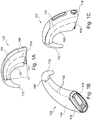
- FIG. 1 illustrates side view of a housing extending completely along a single curved axis and made of a single inseparable unit according to an embodiment of the disclosure.
- Fig. 1B illustrates a first isometric view of the housing extending completely along a single curved axis and made of a single inseparable unit according to an embodiment of the disclosure.
- Fig. 1C illustrates a second isometric view of the housing extending completely along a single curved axis and made of a single inseparable unit according to an embodiment of the disclosure.
- Fig. 1A illustrates side view of a housing extending completely along a single curved axis and made of a single inseparable unit according to an embodiment of the disclosure.
- Fig. 1B illustrates a first isometric view of the housing extending completely along a single curved axis and made of a single inseparable unit according to an embodiment of the disclosure.
- Fig. 1C illustrates a
- FIG. 1D illustrates the housing extending completely along a single curved axis and made of a single inseparable unit according to an embodiment of the disclosure.
- Fig. IE illustrates the housing extending completely along a single curved axis and made of a single inseparable unit according to an embodiment of the disclosure.
- a behind-the-ear (BTE) hearing aid unit 102 includes a housing 104 comprising a hollow inner section (Fig. IE, 106) defined by an enclosed wall surface 108 made of a single inseparable unit.
- the unit further includes an electronic module (Fig. IE, 110); and an ear hook 112 that is permanently or detachably attached to the housing 104.
- the housing 104 extends completely along a single curved axis 114 running along the enclosed wall surface 108 from a first end 116 of the housing comprising the ear hook 112 and a second end 118 of the housing 104 opposite to the ear hook 112.
- the housing 104 comprises an inlet opening (Fig.
- the inlet opening 120 being adapted to receive the electronic module (Fig. IE, 110) in the hollow inner section 106 and the electronic module (Fig. IE, 110) is adapted to move from the inlet opening (Fig. IE, 120) along the single curved axis 114.
- the lines along the surface from the first end to the second end in Figs. 1A and 1E only illustrate the curved sections of the housing and should not to be construed as parting lines
- the single curved axis 114 comprises a rotational axis defined by an arc selected from a group comprising a circular arc, substantially circular arc and parabolic arc.
- the rotational axis may be around a center point C.
- the center point C around which the rotation axis is made may define the single curved axis 114.
- the hearing aid unit 102 further includes a closing structure ( Fig. 1D , 122) at the first end 116 of the housing 104.
- the closing structure 122 is part of the single inseparable unit.
- the BTE hearing aid unit 102 further includes a cover 124 adapted to sealably close the hollow inner section 106 at the second end 118.
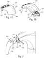
- Fig. 2 illustrates an ear hook according to an embodiment of the disclosure.
- the closing structure 122 or ear hook 112 comprises a protruded part 202 and another of the closing structure 122 or ear hook 112 comprises a receiving section 204.
- the protruded part 202 and the receiving section 204 are configured to couple with each other such that the ear hook 112 and the housing 104 are immovable in lateral directions L relative to each other.
- the coupling of the protruded part 202 and the receiving section 204 is configured to align a through-going hole 206 of the ear hook 112 and a through-going hole 208 of the housing 104 such that the aligned through-going holes (206, 208) are configured to receive an attachment unit 210 to immovably attach the detachably attached ear hook 112 to the housing 104.
- FIG. 3 illustrates the housing and an attachable module according to an embodiment of the disclosure.
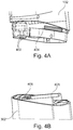
- Fig. 4A illustrates a sliding guide rail according to an embodiment of the disclosure.
- Fig. 4B illustrates an interacting means according to an embodiment of the disclosure.
- the BTE hearing aid unit 102 further includes a cover 124 adapted to sealably close the hollow inner section ( Fig. 1 , 106) at the second end 118.
- the cover includes a first set of connectors ( Fig. 4A , 402) adapted to establish electrical connection with the electronic module ( Fig. 1 , 110) with one end of the first set of connectors being accessible from outside the hollow inner section ( Fig. 4A , 402 represents the one end).
- the hearing aid unit further includes a sliding guide rail 404 configured to receive an attachable module 302 comprising a second set of connectors 406 and an interacting means 408 adapted to run along the guide rail 404 to establish a mechanical connection between the housing 104 and the attachable module 302 and an electrical connection between the one end 402 of the first set of connectors and second set of connectors 406.
- the BTE hearing aid unit and the attachable module are adapted to be locked using a locking mechanism 304.
- the locking mechanism may utilize a rotational locking means as disclosed in EP application EP16178631 .
- the locking means 304 is incorporated with a plug port ( Fig. 7A , 702) functionality as disclosed in EP application EP16178631 .
- Fig. 5A illustrates a microphone inlet cover according to an embodiment of the disclosure
- Fig. 5B illustrates a first side view of a microphone assembly comprising a sound inlet channel according to an embodiment of the disclosure
- Fig. 5C illustrates a second side view of the microphone assembly according to an embodiment of the disclosure.
- the BTE hearing aid unit 102 includes a microphone inlet cover 502 adapted to attach to the housing to form a continuous concave shaped 504 outer surface with the housing, the microphone inlet cover 502 in cooperation with a housing exterior surface 126 is adapted to form sound inlet channel 506 adapted to allow ambient sound to travel from an entry 508 of the sound inlet channel 506 to an inlet port 510 of a microphone 512 that is comprised within the hollow inner section.
- the microphone inlet cover and the housing may include attachment means 532 such as snap locking mechanism.
- the BTE hearing aid unit includes an alignment pin 514 comprising a first end 516 is configured to be received within a receiving hole 518 across the housing and comprised at a chassis 540 holding the microphone 512, the chassis 540 being positioned within the housing 104.
- the chassis 540 may provide a support for a circuit board 542 to which the microphone is connected.
- the alignment pin 514 is adapted to align the microphone 512 with respect to an inlet 528 and housing 104. As the alignment pin is configured to go only in the receiving hole 518 of the chassis, the chassis 540 is positioned precisely in the housing 104 and the microphone(s) 512 is thus properly aligned with the inlet 528.
- the alignment pin 514 further includes a second end 520 configured to be received within a recess 522 at an inner surface 524 of the microphone inlet cover 502.
- the alignment pin 514 is also adapted to provide an aligned position of the microphone inlet cover 502 over the housing exterior surface 126, thereby creating desired inlet channels.
- the alignment pin 514 is preferably positioned in the receiving hole 518 with an sealing material 526 sandwiched therebetween to avoid entry of dirt or liquid.
- the BTE hearing aid unit includes an inlet 528 aligned to the inlet port 510 of the microphone 512.
- the inlet 528 is attached to the housing 104 with a sealing material 530 interposed between the inlet 528 and side surface of the housing.
- the inlet channel 506 includes a wall barrier 534 comprising a height h that is lower than height H of the inlet channel 506 at a location 536 where the wall barrier 534 is positioned.
- the wall barrier 534 runs along a substantial length 538 of the entry 508 of the sound inlet channel 506, i.e. along the single curved axis ( Fig. 1 , 114).
- the wall barrier is typically positioned such that a distance between the wall barrier 534 and the entry 508 of the sound inlet channel 506 is smaller than the distance between the barrier wall 534 and the inlet port 510 of the microphone 512.
- the referred distance is measured along the channel path, i.e. the path 546 that sound/ air follows to travel from the entry 508 to inlet port 510 of the microphone 512.
- the microphone is connected to a chassis 540.
- the chassis 540 may further support a circuit board 542 to which the microphone 512 is electrically connected.
- the sound inlet channel 506 may be adapted by varying dimensions of the sound inlet channel 506 in order to avoid turbulent flow of air flowing at least in a part of the sound inlet channel 506.
- a sound inlet channel 506 comprising a volumetric chamber 544 at least directly above the microphone 512, preferably above the inlet 528.
- the dimensions of the volumetric chamber 544 are adapted to bring pressure and/ or flow velocity of air flowing within the volumetric chamber 544 substantially close to zero.
- the volumetric chamber 544 is defined by a cut out section 548 at the inner surface of the microphone inlet cover 502 that is adapted to be at least directly above the microphone 512, preferably above the inlet 528.
- the cut out section 548 in combination with the sound inlet channel that is at least directly above the microphone 512, preferably above the inlet 528 forms a cross sectional area that is substantially larger than cross sectional area of rest of the sound inlet channel 506.
- the cross-sectional area refers to cross sectional area, as viewed from at least one a first direction X and a second direction Y, the first direction X and the second direction Y being orthogonal to each other. This allows for avoiding turbulent flow within the volumetric chamber and reducing the wind noise.
- Fig. 6A illustrates a push button assembly according to an embodiment of the disclosure.
- Fig. 6B illustrates a cross-sectional view of the push button assembly according to an embodiment of the disclosure;
- the housing exterior surface 126 of the housing 104 includes a push button slot 602 includes at least one slot 604 to receive at least one push actuator 606 and a fixing means slot 608.
- the at least one push actuator 606 is adapted to be fixedly positioned within the at least one slot 604 with a sealing material 610 interposed between the push actuator 606 and side surface of the push button slot 604, as shown in Fig. 6B .
- the BTE hearing aid unit further includes a push button cover 612 and a fixing means 614.
- the push button cover 612 is adapted to cover the at least one push actuator 606, and the fixing means 614 is adapted to pass through the push button cover (for example see 616) and to be received within the fixing means slot 608 in order to attach the push button cover 612 with the housing 104.
- Fig. 7A illustrates a plug port according to an embodiment of the disclosure
- Fig. 7B illustrates a connector socket and cable according to an embodiment of the disclosure
- Fig. 7C illustrates a cross-sectional view of plug port, connector socket and multi-connector according to an embodiment of the disclosure.
- the BTE hearing aid unit includes a plug port 702 across thickness of the housing 104.
- the plug port 702 is adapted to receive a cable 704 into the housing 104 and provide the cable 704 access to a connector socket 706 that is adapted to be positioned within the housing and provide electrical connection between the electronic module (Fig. IE, 110) and cable 704.
- the BTE hearing aid unit further includes a connector socket 706 that is positioned within the housing 104 such that the connector socket 706 is along same longitudinal axis 710 as a multi-connector 708 positioned within the housing 104.
- the multi-connector 708 is adapted to provide electrical connection between the electronic module 104 and the attachment module.
- the multi-connector 708 is the first set of connectors ( Fig. 4A , 402) adapted to establish electrical connection with the electronic module with one end of the first set of connectors being accessible from outside the hollow inner section 106. The one end of the first set of connectors accessible from the outside is used to connect the hearing aid device unit with other devices like battery module or programming system.
- the cable may be provided with a first locking means 716 ( Fig. 7B ) that is adapted to lock with a second locking means 714 ( Fig. 7C ) of the connector socket 706.
- the locking thus provides a reliable mechanical and electrical connection 712 between the cable 704 and connector socket 706.
- One of the first locking means or second locking means may include a recess while the other of the first locking means or second locking means includes a projection, whereby the projection is adapted to be received in the recess in order to provide a snap locking.
- the entire connector socket 706 is positioned inside the housing 102 such that the cable 706 is received within the housing with cable strain relief 718 partially received within the housing 104 and substantially protruding out of the housing 102.
- Fig. 8 illustrates a hearing aid comprising the housing according to an embodiment of the disclosure.
- the BTE hearing aid unit 102 is a sound processor of a hearing aid 802 such as a cochlear implant system.
- a hearing aid 802 includes the hearing aid unit 102 described hereinabove in one or more embodiments is included.
- the hearing aid may include one of a cochlear implant.
- an external part of the cochlear implant system is shown.
- the figure illustrates the BTE hearing aid unit 102 comprising the housing 104 described above, and including the ear hook 112, push button assembly 804, For details see Fig. 6A-6B ), microphone assembly 806 (for details see Figs. 5A-5C ), plug port assembly 808 (for details see Figs. 7A - 7C ).
- An attachment module 302 (in this case a detachable battery) is shown to be attached with the BTE hearing aid unit 102 (for details, see Figs. 3 , and 4A-4B ).
- a cable 704 is shown to be connected to the BTE hearing aid unit 102 at one end and on the other end, the cable 704 is connected to an antenna 810 that is adapted to inductively transmit, to the implantable part, the processed signal received from the electronic module (Fig. IE, 110).
- the implantable part utilizes the signal received from the antenna to generate a number of stimulation pulses that are delivered to a number of electrodes, which are implantable in different locations of the cochlea allowing a stimulation of different frequencies of the audible range.
- connection or “coupled” as used herein may include wirelessly connected or coupled.
- the term “and/or” includes any and all combinations of one or more of the associated listed items. The steps of any disclosed method are not limited to the exact order stated herein, unless expressly stated otherwise.
Description
- The disclosure relates to a hearing aid. In particular, the disclosure relates to a behind-the-ear (BTE) hearing aid unit, which may be a sound processor for a cochlear implant. The BTE hearing aid unit includes a housing comprising a hollow inner section extending completely along a single curved axis and made of a single inseparable unit.
- Medical electronic devices have become indispensable. Such devices include a hearing aid as well. A hearing aid is a device for aiding an individual in regard to his or her hearing. It is generally used to compensate a hearing loss, namely a conventional acoustic hearing aid amplifying sound, or a cochlear implant that electrically stimulates nerve cells or a bone conduction hearing aid. It may also be a hearing protection device which helps individuals to hear without damage in noisy environments. It may also be a tinnitus treatment device.
- BTE hearing aid units such as traditional BTE hearing aids comprise a partially longitudinal, hook-shaped shell running substantially along a longitudinal axis and containing electronic components within the shell. One shell end, usually the tapering end, constitutes the ear hook that is used to rest the hearing aid unit on and behind a user's ear. Generally, the shell is made of two lengthwise parts that are joined together to form the shell. The electronic components are placed on top of inner surface of one of the parts before the two parts are joined together. This type of shell suffers from a number of drawbacks:
- i) because the shell includes two parts, the shell may be weaker along the line where two parts are joined together and thus susceptible to breakage;
- ii) additional sealing material is required along the line where the two parts join. However, despite the sealing provided along the line where the two parts are joined together, the shell is vulnerable to dirt and liquid including user's sweat entering the shell along the line because parting lines of this nature are very difficult to seal. Ingress of liquid inside the shell may even lead to corrosion of electronic components and possibility of a short circuit, and
- iii) the assembly of the electronic components need to precise in order to reliably join the two parts together.
- The disclosure proposes a solution that overcomes the aforementioned drawbacks.
- According to an embodiment, a behind-the-ear (BTE) hearing aid unit is disclosed. The unit includes a housing comprising a hollow inner section defined by an enclosed wall surface made of a single inseparable unit, an electronic module, and an ear hook that is permanently or detachably attached to the housing. The housing extends completely along a single curved axis running along the enclosed wall surface from a first end of the housing comprising the ear hook and a second end of the housing opposite to the ear hook. The housing comprises an inlet opening at the second end, wherein the inlet opening is adapted to receive the electronic module in the hollow inner section and the electronic module is adapted to move from the inlet opening along the single curved axis.
- The single inseparable unit is devoid of any parting lines or segments between enclosed wall surface that forms the hollow inner section. This means that the hollow inner section defining a shell cannot be opened up in separate pieces, i.e. the housing is adapted to avoid being opened in separate pieces. This allows for avoiding access to the hollow inner section along the wall surface. As the wall surface does not include any provision for providing access to the hollow inner section, the protection of the electronic module/ hollow inner section against dirt, sweat, humidity, water, etc. is significantly and mechanical strength of the hearing aid unit is increased. This may be particularly useful because the wall surface is typically exposed to and facing either user skin or environment during usage of a BTE hearing aid unit.
- In an embodiment, the single curved axis may be defined by an arc such as a rotational axis. A center point around which the rotation axis is made may define the single curved axis. The arc may include i) a circular arc or a substantially circular arc. These arc may be understood as an arc of a segment of a circle or a substantial circular shape respectively, or ii) a parabolic arc, which may be understood as a segment of a parabolic arc. Thus, the curve axis is a rotational axis along which the electronic module is adapted to rotate during insertion of the electronic module into the hollow inner section. In an embodiment, the rotational axis may be adapted to substantially match curvature of a depression behind outer ear next to the head, i.e. auricular sulcus of the user. In another embodiment, the rotational axis may be adapted to substantially match a curvature of depression behind outer ear next to the head, i.e. auricular sulcus of at least 50% of a sample population.
- Having the housing extending completely along a single curved axis is useful because an inner curvature, which is adapted to abut the user's ear, of the enclosed wall surface is likely to provide a better compliance with the behind-the-ear periphery of the user's ear. This allows for the hearing aid unit resting over a user's ear in more comfortable and reliable manner. According to an embodiment, the electronic module is fabricated on a chassis extending along a chassis axis that resembles the single curved axis. The term resembles indicate that the chassis axis and the single curved axis are at least substantially same. This allows the electronic module to move freely in a swift motion along the rotational axis within the hollow inner section from the inlet opening along the single curved axis during assembly. This is particularly useful in comparison to shells that include a combination of longitudinal axis and curved axis, where referred free movement of chassis is not possible, thus requiring a longer time and more complicated procedures during assembly. Additionally, the length of the electronic module may be matched with length of the hollow inner section, the length being along the single curved axis.
- The electronic module includes at least a processor, which is adapted to process an incoming signal that is used to compensate for the hearing loss of the user. Additionally, the electronic module may further include a microphone, which is adapted to receive a sound and generating the incoming signal that is provided to the processor. In one embodiment, the electronic module may include and electro-mechanical transducer such as a speaker. In another embodiment, the electronic module includes a memory and/ or a number of connectors for example, a connector for a cable of a cochlear implant connecting the BTE hearing aid unit (e.g. sound processor) to an antenna, and/ or multi-connector for connecting the processor with other devices like hearing aid programming system or a battery module or other attachment modules. In yet another embodiment, the electronic module may include power management unit including battery and connection between the battery and other electronic components such as processor. In other embodiments, electronic components like T-coil that are generally included in known hearing aid may also be included in the housing.
- The second end may be understood as a base end of the BTE hearing aid unit, the base end being devoid of a connection to the ear hook.
- According to an embodiment, the BTE hearing aid unit includes a closing structure at the first end of the housing, the closing structure being part of the single inseparable unit. Thus, the closing structure is an integral part of the single inseparable unit without any parting lines either at the closing structure or at the interface between the closing structure and the enclosed wall surface. This allows for avoiding access to the hollow inner section from the closing structure or the interface and protecting of the electronic module/ hollow inner section against dirt, sweat, humidity, water, etc, and additionally also provides mechanical strength.
- According to an embodiment, the closing structure or ear hook comprises a protruded part and another of the closing structure or ear hook comprises a receiving section. The protruded part and the receiving section are configured to couple with each other such that the ear hook and the housing are immovable in lateral directions relative to each other. The lateral directions comprise direction sideways with respect to extrapolated axis, extending outwards from the first end, of the single curved axis. In one embodiment, the protruded part and the receiving part includes threads that are adapted to cooperate with one to allow screwing of the ear hook to the housing. In another embodiment, the coupling of the protruded part and the receiving section are configured to align a through-going hole of the ear hook and a through-going hole of the housing such that the aligned through-going holes are configured to receive an attachment unit that is adapted to immovably attach the detachably attached ear hook to the housing. The attachment unit such as a pin may be configured to go either partially or completely through combined width of the protruded part and the receiving section.
- Hereby, it is possible to provide a reliable and simple mechanical way of fixing the ear hook to the housing.
- According to an embodiment, a hearing aid is disclosed. The hearing aid includes a housing adapted to house the electronic module. The hearing aid housing further comprises an ear hook and a structure at the hook end of the housing. The structure and the ear hook includes features disclosed hereinabove with respect to the closing structure and ear hook respectively, i.e. structure or ear hook comprises a protruded part and another of the closing structure or ear hook comprises a receiving section, the protruded part and the receiving section being configured to couple with each other such that the ear hook and the housing are immovable in lateral directions relative to each other. In a further embodiment, the coupling of the protruded part and the receiving section is configured to align a through-going hole of the ear hook and a through-going hole of the housing such that the aligned through-going holes are configured to receive an attachment unit to immovably attach the detachably attached ear hook to the housing. Although it may be useful for the housing comprising a hollow inner section extending completely along a single curved axis and made of a single inseparable unit but in this embodiment, the housing may not necessarily include a single inseparable unit extending completely along a single curved axis.
- The BTE hearing aid unit includes a cover adapted to sealably close the hollow inner section at the second end, i.e. closing the inlet opening. The cover may be molded with the housing during the assembly. The cover includes a first set of connectors such as electrical slots and guide channels. The first set of connectors i) is adapted to establish electrical connection with the electronic module and ii) comprises one end that is accessible from outside the hollow inner section. The guide channel is configured to receive an attachable module comprising a second set of connectors such as electrical pins and an interacting means adapted to run along the guide channel to establish a mechanical connection between the housing and the attachable module and an electrical connection between the one end of the first set of connectors and second set of connectors.
- In an embodiment, the BTE hearing aid unit and the attachable module may include an alignment structure in order to align the one end of the first set of connectors and second set of connectors. In an embodiment, the BTE hearing aid unit and the attachable module are adapted to be locked using a locking mechanism.
- In different embodiments, the attachable module may include a battery compartment, or fm receiver or programming interface or any other module that provides additional functionality to the hearing aid unit.
- The sliding mechanism to establish mechanical and electrical connection is disclosed in
Figure 2 (disclosing generally a sliding mechanism) and description ofFigure 2 along with related text in the Summary section,Figure 6 (disclosing details of the guide channels, which may be present at both the BTE hearing aid unit and attachable module) and description ofFigure 6 along with related text in the Summary section, 7 (disclosing alignment structure), and Figure 9 (disclosing details of the guide channel and the interacting means) and description of Figure 9 along with related text in the Summary section of the pending EP applicationEP16178631 Figure 3 (locking mechanism comprising a moveable unit) and description ofFigure 3 along with related text in the Summary section,,Figure 4 (disclosing a friction element) and description ofFigure 4 along with related text in the Summary section,Figure 5 (disclosing a stop member) and description ofFigure 5 along with related text in the Summary section of the pending EP applicationEP16178631 Figures 1 and2 and description of these figures along with related text in the Summary section of the pending EP applicationEP16178631 EP16178631 - According to an embodiment, the BTE hearing aid unit includes a microphone inlet cover adapted to attach to the housing to form a continuous concave shaped outer surface with the housing. The microphone inlet cover and the housing may include attachment means such as snap locking mechanism. The microphone inlet cover in cooperation with the housing exterior surface is adapted to form sound inlet channel adapted to allow ambient sound to travel from an entry of the sound inlet channel to an inlet port of a microphone that is comprised within the hollow inner section. The entry of the sound inlet channel is from side surface of the enclosed wall surface.
- In one embodiment, the sound inlet channel may be adapted by varying dimensions of the sound inlet channel in order to avoid turbulent flow of air flowing at least in a part of the sound inlet channel. In an embodiment, the sound inlet channel comprising a volumetric chamber at least directly above the microphone, preferably above the inlet. The dimensions of the volumetric chamber are adapted to bring pressure and/ or flow velocity of air flowing within the volumetric chamber substantially close to zero. The volumetric chamber is defined by a cut out section at the inner surface of the microphone inlet cover that is adapted to be at least directly above the microphone, preferably above the inlet. The cut out section in combination with the sound inlet channel that is at least directly above the microphone, preferably above the inlet forms a cross sectional area that is substantially larger than cross sectional area of rest of the sound inlet channel. The cross-sectional area refers to cross sectional area, as viewed from at least one a first direction and a second direction, the first direction and the second direction being orthogonal to each other. This allows for avoiding turbulent flow within the volumetric chamber and reducing the wind noise. According to another embodiment, dimensions of sound inlet channel the sound inlet channel is adapted to optimize wind noise suppression with respect to acoustic attenuation. Such optimization would result in an improved intelligibility of the signal. In both embodiments, the dimensions may include length of the channel from the entry of the sound inlet channel to the inlet port and/ or cross-sectional dimensions of the sound inlet channel.
- In an embodiment, the inlet channel includes capillary stop to minimize liquid ingress into microphones. In an embodiment, the inlet channel includes a wall barrier comprising a height that is lower than height of the inlet channel at the location where the wall barrier is positioned. The wall barrier runs along a substantial length of the entry of the sound inlet channel, i.e. along the single curved axis. The wall barrier is typically positioned such that a distance between the wall barrier and the entry of the sound inlet channel inlet is smaller than the distance between the barrier wall and the inlet port of the microphone. The referred distance is measured along the channel path, i.e. the path that sound/ air follows to travel from the entry to inlet port of the microphone. The barrier wall allows for preventing ingress of moisture, grease, dirt, water, etc.
- According to an embodiment, the BTE hearing aid unit includes an alignment pin comprising a first end configured to be received within a receiving hole across the housing and comprised at a chassis holding the microphone, the chassis being positioned within the housing and the alignment pin being adapted to align the microphone with respect to an inlet and housing. The chassis may also provide a support for a circuit board to which the microphone is connected. As the alignment pin is configured to go only in the receiving hole of the chassis, the chassis is positioned precisely in the housing and the microphone(s) are thus properly aligned with the inlet. This is particularly useful so that the liquid/ dust tight seal may be created between the inlet and housing. In an embodiment, the alignment pin further includes a second end configured to be received within a recess at an inner surface of the microphone inlet cover. The alignment pin thus also adapted to provide an aligned position of the microphone inlet cover over the housing exterior surface, thereby creating desired inlet channels. The inner surface of the microphone inlet cover and the exterior surface of the housing cooperating with the microphone inlet cover are adapted to be concealed when the microphone inlet cover is in position. In the combinable embodiments recited in this paragraph, the alignment pin is typically positioned substantially perpendicular to the single curve axis.
- According to an embodiment, the BTE hearing aid unit includes an inlet aligned to the inlet port of the microphone. The inlet is attached to the housing with a sealing material interposed between the inlet and side surface of the housing. The sealing material provides a seal between the sound inlet channel and hollow inner shell. Thus, the sound can travel to the electronic module by entering from the entry of the sound inlet channel, travelling through the sound inlet channel, entering the inlet and finally entering the microphone from the inlet port of the microphone.
- According to an embodiment, a hearing aid is disclosed. The hearing aid includes a housing adapted to house the electronic module. The hearing aid housing may further include an ear hook. In addition, the hearing aid includes a microphone inlet cover adapted to attach to the housing to form a continuous concave shaped outer surface with the housing, the microphone inlet cover in cooperation with the housing exterior surface is adapted to form sound inlet channel adapted to allow ambient sound to travel from an entry of the sound inlet channel to an inlet port of a microphone that is comprised within the hollow inner section. Additionally, the hearing aid may include an alignment pin comprising a first end configured to be received within a receiving hole across the housing and comprised at a chassis holding the microphone, the chassis being positioned within the housing and the alignment pin being adapted to align the microphone with respect to an inlet and housing. Additionally, the alignment pin further includes a second end configured to be received within a recess at an inner surface of the microphone inlet cover. In an embodiment, the hearing aid also includes an inlet aligned to the inlet port of the microphone, the inlet being attached to the housing with a sealing material interposed between the inlet and side surface of the housing. The hearing aid may further include features relating to positioning of microphone inlet cover that are described above in earlier embodiments. In another embodiment, the hearing aid further includes the volumetric chamber as disclosed previously. Although it may be useful for the housing comprising a hollow inner section extending completely along a single curved axis and made of a single inseparable unit but in this embodiment, the housing may not necessarily include a single inseparable unit extending completely along a single curved axis.
- According to an embodiment, the housing exterior surface comprises a push button slot comprising at least one slot to receive at least one push actuator and a fixing means slot. In an embodiment, the fixing means slot extends beyond the curved concave exterior surface of the housing.
- According to an embodiment, the at least one push actuator is adapted to be fixedly positioned within the at least one slot with a sealing material interposed between the push actuator and side surface of the push button slot. The interposed sealing material is adapted to seal the hollow inner section against dirt, dust or sweat, etc.
- According to an embodiment, the BTE hearing aid unit includes a push button cover and a fixing means. The push button cover is adapted to cover the at least one push actuator. The fixing means is adapted to pass through the push button cover and to be received within the fixing means slot in order to attach the push button cover with the housing.
- In one embodiment, the fixing means include a pin adapted to pass through the push button cover and the fixing means slot include adjacent walls positioned within the push button slot, the adjacent walls being configured to receive the pin and lock the pin by snapping length of the pin between the adjacent walls. In another embodiment, the fixing means include a pin and the fixing means slot include a tunnel running, at least partially, across the push button slot. The push button cover includes holes on both sides of cover wall, wherein the holes are configured to align with the tunnel such that the pin is adapted to pass through the holes and tunnel in order to provide attachment between the push button cover and the housing.
- The push button may be programmed to perform different functions. For example, the push button may be used to one or more of many tasks change volume, change program, put the hearing aid in different functional mode or any other function that is generally known in the art.
- According to an embodiment, a hearing aid is disclosed. The hearing aid includes a housing adapted to house the electronic module. The hearing aid housing may further include an ear hook. In an embodiment, the housing exterior surface comprises a push button slot comprising at least one slot to receive at least one push actuator and a fixing means slot. In another embodiment, at least one push actuator is adapted to be fixedly positioned within the at least one slot with a sealing material interposed between the push actuator and side surface of the push button slot. In another embodiment, a push button cover adapted to cover the at least one push actuator; and a fixing means adapted to pass through the push button cover and to be received within the fixing means slot in order to attach the push button cover with the housing. The hearing aid may further include features relating to the push button and its arrangement over the housing that are described above in earlier embodiments. Although it may be useful for the housing comprising a hollow inner section extending completely along a single curved axis and made of a single inseparable unit but in this embodiment, the housing may not necessarily include a single inseparable unit extending completely along a single curved axis.
- According to an embodiment, the BTE hearing aid unit includes a plug port across the housing. The plug port is adapted to receive a cable into the housing and provide the cable access to a connector socket (such as T2 socket) that is adapted to provide electrical connection between the electronic module and cable. In an embodiment, the cable received within the housing has its first end electrically connected to the electronic module and second end connected to an antenna for example like in cochlear implant system. Thus the processed audio signal, using the cable, is transmitted from the BTE hearing aid unit to the antenna.
- In one embodiment, the entire connector socket is positioned inside the housing such that the cable is received within the housing with cable strain relief partially received within the housing and substantially protruding out of the housing.
- According to an embodiment, the connector socket is positioned within the housing such that the connector socket is along same longitudinal axis as a multi-connector (such as the first set of connectors as disclosed previously) positioned within the housing, the multi-connector is adapted to provide connection between the electronic module and other auxiliary devices such as the attachment module. As the connectors are lined up along the width of the hearing aid unit, providing the cable connector socket in same longitudinal axis as the multi-connector axis allows for optimally positioning the connectors and utilizing space within the hollow inner section. This, thus allows for reducing the size of the BTE hearing aid unit. The multi-connector may be utilized to electrically connect the hearing aid unit to other devices like attachment module that may including a programming system. In an embodiment, the multi-connector is the first set of connectors adapted to establish electrical connection with the electronic module with one end of the first set of connectors being accessible from outside the hollow inner section. The one end of the first set of connectors accessible from the outside is used to connect the hearing aid device unit with other devices.
- The longitudinal axis is typically along the width of the housing along the two curved surface of the shell. Usually, the connector socket is positioned proximal to the plug port whereas the multi-connector is distal from the plug port along the same longitudinal axis.
- According to an embodiment, a hearing aid is disclosed. The hearing aid includes a housing adapted to house the electronic module. The hearing aid housing may further include an ear hook. In an embodiment, comprising a plug port across the housing, the plug port being adapted to receive a cable into the housing and provide the cable access to a connector socket that is adapted to provide electrical connection between the electronic module and cable. In another embodiment, the connector socket is positioned within the housing such that the connector socket is along same longitudinal axis as a multi-connector positioned within the housing, the multi-connector is adapted to provide connection between the electronic module and other auxiliary devices. The hearing aid may further include features relating to the plug port, connector socket and multi-connector that are described above in earlier embodiments. Although it may be useful for the housing comprising a hollow inner section extending completely along a single curved axis and made of a single inseparable unit but in this embodiment, the housing may not necessarily include a single inseparable unit extending completely along a single curved axis.
- According to an embodiment, the BTE hearing aid unit is a sound processor of a hearing aid such as a cochlear implant system. In another embodiment, the BTE hearing aid unit includes a sound processor for a bone conduction hearing aid. In another embodiment, the BTE hearing aid unit includes sound processor for an acoustic hearing aid.
- According to another embodiment, a hearing aid comprising the hearing aid unit described hereinabove in one or more embodiments is included. The hearing aid may include one of a cochlear implant, a bone conduction hearing aid and an acoustic hearing aid.
- According to an embodiment, a method for manufacturing the BTE hearing aid unit is disclosed. The method includes preparing a housing comprising a hollow inner section defined by an enclosed wall surface, and preferably with a closing structure at a first end, made of a single inseparable unit and extending completely along a single curved axis, fabricating the electronic module on a chassis extending along a chassis axis resembling the single curved axis, and inserting the chassis through an inlet opening of the housing along the single curved axis, and sealably closing the inlet opening using a cover. The closing structure may include an integrated ear hook or means for detachably attaching the ear hook.
- The aspects of the disclosure may be best understood from the following detailed description taken in conjunction with the accompanying figures. The figures are schematic and simplified for clarity, and they just show details to improve the understanding of the claims, while other details are left out. The individual features of each aspect may each be combined with any or all features of the other aspects. These and other aspects, features and/or technical effect will be apparent from and elucidated with reference to the illustrations described hereinafter in which:
-
Fig. 1A illustrates side view of a housing extending completely along a single curved axis and made of a single inseparable unit according to an embodiment of the disclosure; -
Fig. 1B illustrates a first isometric view of the housing extending completely along a single curved axis and made of a single inseparable unit according to an embodiment of the disclosure; -
Fig. 1C illustrates a second isometric view of the housing extending completely along a single curved axis and made of a single inseparable unit according to an embodiment of the disclosure; - Fig. ID illustrates the housing extending completely along a single curved axis and made of a single inseparable unit according to an embodiment of the disclosure;
- Fig. IE illustrates the housing extending completely along a single curved axis and made of a single inseparable unit according to an embodiment of the disclosure;
-
Fig. 2 illustrates an ear hook according to an embodiment of the disclosure; -
Fig. 3 illustrates the housing and an attachable module according to an embodiment of the disclosure; -
Fig. 4A illustrates a sliding guide rail according to an embodiment of the disclosure; -
Fig. 4B illustrates an interacting means according to an embodiment of the disclosure; -
Fig. 5A illustrates a microphone inlet cover according to an embodiment of the disclosure; -
Fig. 5B illustrates a first side view of a microphone assembly comprising a sound inlet channel according to an embodiment of the disclosure; -
Fig. 5C illustrates a second side view of the microphone assembly according to an embodiment of the disclosure; -
Fig. 6A illustrates a push button assembly according to an embodiment of the disclosure; -
Fig. 6B illustrates a cross-sectional view of the push button assembly according to an embodiment of the disclosure; -
Fig. 7A illustrates a plug port according to an embodiment of the disclosure; -
Fig. 7B illustrates a connector socket and cable according to an embodiment of the disclosure; -
Fig. 7C illustrates a cross-sectional view of plug port, connector socket and multi-connector according to an embodiment of the disclosure; and -
Fig. 8 illustrates a hearing aid comprising the housing according to an embodiment of the disclosure. - The detailed description set forth below in connection with the appended drawings is intended as a description of various configurations. The detailed description includes specific details for the purpose of providing a thorough understanding of various concepts. However, it will be apparent to those skilled in the art that these concepts may be practised without these specific details. Several aspects of the apparatus and methods are described by various blocks, functional units, modules, components, etc.
- In the description below, same reference numeral generally illustrates the same component of the hearing aid device.
- In general, a hearing aid is adapted to improve or augment the hearing capability of a user by receiving an acoustic signal from a user's surroundings, generating a corresponding audio signal, modifying the audio signal and providing the modified audio signal as an audible signal to at least one of the user's ears. The "hearing aid" may further refer to a device such as an earphone or a headset adapted to receive an audio signal electronically, possibly modifying the audio signal and providing the possibly modified audio signals as an audible signal to at least one of the user's ears. Such audible signals may be provided in the form of an acoustic signal radiated into the user's outer ear, or an acoustic signal transferred as mechanical vibrations to the user's inner ears through bone structure of the user's head and/or through parts of middle ear of the user or electric signals transferred directly or indirectly to cochlear nerve and/or to auditory cortex of the user.
- At least a part or entire hearing aid is adapted to be worn in any known way. This may include i) arranging a unit of the hearing device behind the ear with a tube leading air-borne acoustic signals into the ear canal or with a receiver/ loudspeaker arranged close to or in the ear canal such as in a Behind-the-Ear type hearing aid. Such hearing aids include a housing comprising electronic module like a processing unit such as a processor and a permanently attached or detachable ear hook that is adapted to position the hearing aid behind the user's ear or ii) Similar Behind-the-Ear type hearing aid type hearing aid arrangement comprising the housing and ear hook may be used in other stimulation types hearing aids for example as a speech processor unit in a cochlear implant or in bone conduction hearing aid.
- The disclosed hearing aid may be part of i) a "hearing system", which refers to a system comprising one or two hearing aids, or ii) a "binaural hearing system", which refers to a system comprising two hearing devices where the devices are adapted to cooperatively provide audible signals to both of the user's ears. In case of the binaural hearing system, the notification may also represent operating state of the system, for example if the connection between the two hearing aids is established or lost. The hearing system or binaural hearing system may further include auxiliary device(s) that communicates with at least one hearing aids, the auxiliary device may affect the operation of the hearing aids and/or benefitting from the functioning of the hearing devices. A wired or wireless communication link between the at least one hearing aid and the auxiliary device may be established that allows for exchanging information (e.g. control and status signals, possibly audio signals) between the at least one hearing device and the auxiliary device. Such auxiliary devices may include at least one of remote controls, remote microphones, audio gateway devices, mobile phones, public-address systems, car audio systems or music players or a combination thereof. The audio gateway is adapted to receive a multitude of audio signals such as from an entertainment device like a TV or a music player, a telephone apparatus like a mobile telephone or a computer, a PC. The audio gateway is further adapted to select and/or combine an appropriate one of the received audio signals (or combination of signals) for transmission to the at least one hearing device. The remote control is adapted to control functionality and operation of the at least one hearing devices. The function of the remote control may be implemented in a SmartPhone or other electronic device, the SmartPhone/ electronic device possibly running an application that controls functionality of the at least one hearing aid.
- In general, the hearing aid includes i) an input unit such as a microphone for receiving an acoustic signal from a user's surroundings and providing a corresponding input audio signal, and/or ii) a receiving unit for electronically receiving an input audio signal. The hearing aid further includes a signal processing unit for processing the input audio signal and an output unit for providing an audible signal to the user in dependence on the processed audio signal.
- The input unit may include multiple input microphones, e.g. for providing direction-dependent audio signal processing. Such directional microphone system is adapted to enhance a target acoustic source among a multitude of acoustic sources in the user's environment. In one aspect, the directional system is adapted to detect (such as adaptively detect) from which direction a particular part of the microphone signal originates. This may be achieved by using conventionally known methods. The signal processing unit may include amplifier that is adapted to apply a frequency dependent gain to the input audio signal. The signal processing unit may further be adapted to provide other relevant functionality such as compression, noise reduction, etc. The output unit may include an output transducer such as a loudspeaker/ receiver for providing an air-borne acoustic signal transcutaneously or percutaneously to the skull bone or a vibrator for providing a structure-borne or liquid-borne acoustic signal. In some hearing devices, the output unit may include one or more output electrodes for providing the electric signals such as in a Cochlear Implant. The Cochlear Implant typically includes i) an external part (speech processor in the housing with a permanently attached or detachable ear hook) for picking up and processing sound from the environment, and for determining sequences of pulses for stimulation of the electrodes in dependence on the current input sound, ii) a (typically wireless, e.g. inductive) communication link for simultaneously transmitting information about the stimulation sequences and for transferring energy to iii) an implanted part allowing the stimulation to be generated and applied to a number of electrodes, which are implantable in different locations of the cochlea allowing a stimulation of different frequencies of the audible range. Such systems are e.g. described in
US 4,207,441 and inUS 4,532,930 . - Referring now to
Fig. 1 , whereFig. 1A illustrates side view of a housing extending completely along a single curved axis and made of a single inseparable unit according to an embodiment of the disclosure.Fig. 1B illustrates a first isometric view of the housing extending completely along a single curved axis and made of a single inseparable unit according to an embodiment of the disclosure.Fig. 1C illustrates a second isometric view of the housing extending completely along a single curved axis and made of a single inseparable unit according to an embodiment of the disclosure.Fig. 1D illustrates the housing extending completely along a single curved axis and made of a single inseparable unit according to an embodiment of the disclosure. Fig. IE illustrates the housing extending completely along a single curved axis and made of a single inseparable unit according to an embodiment of the disclosure. - A behind-the-ear (BTE)
hearing aid unit 102 includes ahousing 104 comprising a hollow inner section (Fig. IE, 106) defined by anenclosed wall surface 108 made of a single inseparable unit. The unit further includes an electronic module (Fig. IE, 110); and anear hook 112 that is permanently or detachably attached to thehousing 104. Thehousing 104 extends completely along a singlecurved axis 114 running along theenclosed wall surface 108 from afirst end 116 of the housing comprising theear hook 112 and asecond end 118 of thehousing 104 opposite to theear hook 112. Thehousing 104 comprises an inlet opening (Fig. IE, 120) at thesecond end 118, theinlet opening 120 being adapted to receive the electronic module (Fig. IE, 110) in the hollowinner section 106 and the electronic module (Fig. IE, 110) is adapted to move from the inlet opening (Fig. IE, 120) along the singlecurved axis 114. (The lines along the surface from the first end to the second end inFigs. 1A and1E only illustrate the curved sections of the housing and should not to be construed as parting lines) - The single
curved axis 114 comprises a rotational axis defined by an arc selected from a group comprising a circular arc, substantially circular arc and parabolic arc. The rotational axis may be around a center point C. In other words, the center point C around which the rotation axis is made may define the singlecurved axis 114. - According to an embodiment, the
hearing aid unit 102 further includes a closing structure (Fig. 1D , 122) at thefirst end 116 of thehousing 104. Theclosing structure 122 is part of the single inseparable unit. - According to an embodiment, the BTE
hearing aid unit 102 further includes acover 124 adapted to sealably close the hollowinner section 106 at thesecond end 118. -
Fig. 2 illustrates an ear hook according to an embodiment of the disclosure. As illustrated, theclosing structure 122 orear hook 112 comprises aprotruded part 202 and another of theclosing structure 122 orear hook 112 comprises a receivingsection 204. Theprotruded part 202 and the receivingsection 204 are configured to couple with each other such that theear hook 112 and thehousing 104 are immovable in lateral directions L relative to each other. - According to an embodiment, the coupling of the
protruded part 202 and the receivingsection 204 is configured to align a through-goinghole 206 of theear hook 112 and a through-goinghole 208 of thehousing 104 such that the aligned through-going holes (206, 208) are configured to receive anattachment unit 210 to immovably attach the detachably attachedear hook 112 to thehousing 104. - Now referring to
Figs. 3 ,4A and 4B , whereFig. 3 illustrates the housing and an attachable module according to an embodiment of the disclosure.Fig. 4A illustrates a sliding guide rail according to an embodiment of the disclosure.Fig. 4B illustrates an interacting means according to an embodiment of the disclosure. - As mentioned earlier, the BTE
hearing aid unit 102 further includes acover 124 adapted to sealably close the hollow inner section (Fig. 1 , 106) at thesecond end 118. The cover includes a first set of connectors (Fig. 4A , 402) adapted to establish electrical connection with the electronic module (Fig. 1 , 110) with one end of the first set of connectors being accessible from outside the hollow inner section (Fig. 4A , 402 represents the one end). The hearing aid unit further includes a slidingguide rail 404 configured to receive anattachable module 302 comprising a second set ofconnectors 406 and an interacting means 408 adapted to run along theguide rail 404 to establish a mechanical connection between thehousing 104 and theattachable module 302 and an electrical connection between the oneend 402 of the first set of connectors and second set ofconnectors 406. - In an embodiment, the BTE hearing aid unit and the attachable module are adapted to be locked using a
locking mechanism 304. The locking mechanism may utilize a rotational locking means as disclosed in EP applicationEP16178631 Fig. 7A , 702) functionality as disclosed in EP applicationEP16178631 Figure 3 (locking mechanism comprising a moveable unit) and description ofFigure 3 along with related text in the Summary section,,Figure 4 (disclosing a friction element) and description ofFigure 4 along with related text in the Summary section,Figure 5 (disclosing a stop member) and description ofFigure 5 along with related text in the Summary section of the pending EP applicationEP16178631 - Referring to
Fig. 5 , whereFig. 5A illustrates a microphone inlet cover according to an embodiment of the disclosure;Fig. 5B illustrates a first side view of a microphone assembly comprising a sound inlet channel according to an embodiment of the disclosure andFig. 5C illustrates a second side view of the microphone assembly according to an embodiment of the disclosure. - According to an embodiment, the BTE
hearing aid unit 102 includes amicrophone inlet cover 502 adapted to attach to the housing to form a continuous concave shaped 504 outer surface with the housing, themicrophone inlet cover 502 in cooperation with ahousing exterior surface 126 is adapted to formsound inlet channel 506 adapted to allow ambient sound to travel from anentry 508 of thesound inlet channel 506 to aninlet port 510 of amicrophone 512 that is comprised within the hollow inner section. - The microphone inlet cover and the housing may include attachment means 532 such as snap locking mechanism.
- According to an embodiment, the BTE hearing aid unit includes an alignment pin 514 comprising a
first end 516 is configured to be received within a receivinghole 518 across the housing and comprised at achassis 540 holding themicrophone 512, thechassis 540 being positioned within thehousing 104. Thechassis 540 may provide a support for acircuit board 542 to which the microphone is connected. The alignment pin 514 is adapted to align themicrophone 512 with respect to aninlet 528 andhousing 104. As the alignment pin is configured to go only in the receivinghole 518 of the chassis, thechassis 540 is positioned precisely in thehousing 104 and the microphone(s) 512 is thus properly aligned with theinlet 528. In an embodiment, the alignment pin 514 further includes a second end 520 configured to be received within arecess 522 at aninner surface 524 of themicrophone inlet cover 502. The alignment pin 514 is also adapted to provide an aligned position of themicrophone inlet cover 502 over thehousing exterior surface 126, thereby creating desired inlet channels. The alignment pin 514 is preferably positioned in the receivinghole 518 with an sealingmaterial 526 sandwiched therebetween to avoid entry of dirt or liquid. - According to an embodiment, the BTE hearing aid unit includes an
inlet 528 aligned to theinlet port 510 of themicrophone 512. Theinlet 528 is attached to thehousing 104 with a sealingmaterial 530 interposed between theinlet 528 and side surface of the housing. - In an embodiment, the
inlet channel 506 includes awall barrier 534 comprising a height h that is lower than height H of theinlet channel 506 at alocation 536 where thewall barrier 534 is positioned. Thewall barrier 534 runs along asubstantial length 538 of theentry 508 of thesound inlet channel 506, i.e. along the single curved axis (Fig. 1 , 114). The wall barrier is typically positioned such that a distance between thewall barrier 534 and theentry 508 of thesound inlet channel 506 is smaller than the distance between thebarrier wall 534 and theinlet port 510 of themicrophone 512. The referred distance is measured along the channel path, i.e. thepath 546 that sound/ air follows to travel from theentry 508 toinlet port 510 of themicrophone 512. - The microphone is connected to a
chassis 540. Thechassis 540 may further support acircuit board 542 to which themicrophone 512 is electrically connected. - In one embodiment, the
sound inlet channel 506 may be adapted by varying dimensions of thesound inlet channel 506 in order to avoid turbulent flow of air flowing at least in a part of thesound inlet channel 506. In an embodiment, asound inlet channel 506 comprising avolumetric chamber 544 at least directly above themicrophone 512, preferably above theinlet 528. The dimensions of thevolumetric chamber 544 are adapted to bring pressure and/ or flow velocity of air flowing within thevolumetric chamber 544 substantially close to zero. Thevolumetric chamber 544 is defined by a cut outsection 548 at the inner surface of themicrophone inlet cover 502 that is adapted to be at least directly above themicrophone 512, preferably above theinlet 528. The cut outsection 548 in combination with the sound inlet channel that is at least directly above themicrophone 512, preferably above theinlet 528 forms a cross sectional area that is substantially larger than cross sectional area of rest of thesound inlet channel 506. The cross-sectional area refers to cross sectional area, as viewed from at least one a first direction X and a second direction Y, the first direction X and the second direction Y being orthogonal to each other. This allows for avoiding turbulent flow within the volumetric chamber and reducing the wind noise. -
Fig. 6A illustrates a push button assembly according to an embodiment of the disclosure.Fig. 6B illustrates a cross-sectional view of the push button assembly according to an embodiment of the disclosure; - According to an embodiment, the
housing exterior surface 126 of thehousing 104 includes apush button slot 602 includes at least oneslot 604 to receive at least onepush actuator 606 and a fixing meansslot 608. The at least onepush actuator 606 is adapted to be fixedly positioned within the at least oneslot 604 with a sealingmaterial 610 interposed between thepush actuator 606 and side surface of thepush button slot 604, as shown inFig. 6B . - According to an embodiment, the BTE hearing aid unit further includes a
push button cover 612 and a fixing means 614. Thepush button cover 612 is adapted to cover the at least onepush actuator 606, and the fixing means 614 is adapted to pass through the push button cover (for example see 616) and to be received within the fixing meansslot 608 in order to attach thepush button cover 612 with thehousing 104. -
Fig. 7A illustrates a plug port according to an embodiment of the disclosure;Fig. 7B illustrates a connector socket and cable according to an embodiment of the disclosure; andFig. 7C illustrates a cross-sectional view of plug port, connector socket and multi-connector according to an embodiment of the disclosure. - According to an embodiment, the BTE hearing aid unit includes a
plug port 702 across thickness of thehousing 104. Theplug port 702 is adapted to receive acable 704 into thehousing 104 and provide thecable 704 access to aconnector socket 706 that is adapted to be positioned within the housing and provide electrical connection between the electronic module (Fig. IE, 110) andcable 704. - According to an embodiment, the BTE hearing aid unit further includes a
connector socket 706 that is positioned within thehousing 104 such that theconnector socket 706 is along samelongitudinal axis 710 as a multi-connector 708 positioned within thehousing 104. The multi-connector 708 is adapted to provide electrical connection between theelectronic module 104 and the attachment module. In an embodiment, the multi-connector 708 is the first set of connectors (Fig. 4A , 402) adapted to establish electrical connection with the electronic module with one end of the first set of connectors being accessible from outside the hollowinner section 106. The one end of the first set of connectors accessible from the outside is used to connect the hearing aid device unit with other devices like battery module or programming system. - The cable may be provided with a first locking means 716 (
Fig. 7B ) that is adapted to lock with a second locking means 714 (Fig. 7C ) of theconnector socket 706. The locking, thus provides a reliable mechanical andelectrical connection 712 between thecable 704 andconnector socket 706. One of the first locking means or second locking means may include a recess while the other of the first locking means or second locking means includes a projection, whereby the projection is adapted to be received in the recess in order to provide a snap locking. - In one embodiment, the
entire connector socket 706 is positioned inside thehousing 102 such that thecable 706 is received within the housing withcable strain relief 718 partially received within thehousing 104 and substantially protruding out of thehousing 102. -
Fig. 8 illustrates a hearing aid comprising the housing according to an embodiment of the disclosure. - According to an embodiment, the BTE
hearing aid unit 102 is a sound processor of ahearing aid 802 such as a cochlear implant system. According to another embodiment, ahearing aid 802 includes thehearing aid unit 102 described hereinabove in one or more embodiments is included. The hearing aid may include one of a cochlear implant. - In the illustrated embodiment, an external part of the cochlear implant system is shown. The figure illustrates the BTE
hearing aid unit 102 comprising thehousing 104 described above, and including theear hook 112,push button assembly 804, For details seeFig. 6A-6B ), microphone assembly 806 (for details seeFigs. 5A-5C ), plug port assembly 808 (for details seeFigs. 7A - 7C ). An attachment module 302 (in this case a detachable battery) is shown to be attached with the BTE hearing aid unit 102 (for details, seeFigs. 3 , and4A-4B ). Acable 704 is shown to be connected to the BTEhearing aid unit 102 at one end and on the other end, thecable 704 is connected to anantenna 810 that is adapted to inductively transmit, to the implantable part, the processed signal received from the electronic module (Fig. IE, 110). The implantable part utilizes the signal received from the antenna to generate a number of stimulation pulses that are delivered to a number of electrodes, which are implantable in different locations of the cochlea allowing a stimulation of different frequencies of the audible range. - As used, the singular forms "a," "an," and "the" are intended to include the plural forms as well (i.e. to have the meaning "at least one"), unless expressly stated otherwise. It will be further understood that the terms "includes," "comprises," "including," and/or "comprising," when used in this specification, specify the presence of stated features, integers, steps, operations, elements, and/or components, but do not preclude the presence or addition of one or more other features, integers, steps, operations, elements, components, and/or groups thereof. It will also be understood that when an element is referred to as being "connected" or "coupled" to another element, it can be directly connected or coupled to the other element but an intervening element may also be present, unless expressly stated otherwise. Furthermore, "connected" or "coupled" as used herein may include wirelessly connected or coupled. As used herein, the term "and/or" includes any and all combinations of one or more of the associated listed items. The steps of any disclosed method are not limited to the exact order stated herein, unless expressly stated otherwise.
- It should be appreciated that reference throughout this specification to "one embodiment" or "an embodiment" or "an aspect" or features included as "may" means that a particular feature, structure or characteristic described in connection with the embodiment is included in at least one embodiment of the disclosure. Furthermore, the particular features, structures or characteristics may be combined as suitable in one or more embodiments of the disclosure. The previous description is provided to enable any person skilled in the art to practice the various aspects described herein.
- The claims are not intended to be limited to the aspects shown herein, but is to be accorded the full scope consistent with the language of the claims, wherein reference to an element in the singular is not intended to mean "one and only one" unless specifically so stated, but rather "one or more." Unless specifically stated otherwise, the term "some" refers to one or more.
- Accordingly, the scope should be judged in terms of the claims that follow.
Claims (14)
- A behind-the-ear (BTE) hearing aid unit (102) comprisinga housing (104) comprising a hollow inner section defined by an enclosed wall surface (108) made of a single inseparable unit;an electronic module (110); andan ear hook (112) that is permanently or detachably attached to the housing; whereinthe housing extends completely along a single curved axis (114) running along the enclosed wall surface from a first end of the housing comprising the ear hook and a second end (118) of the housing opposite to the ear hook, andthe housing comprises an inlet opening (120) at the second end, the inlet opening being adapted to receive the electronic module in the hollow inner section and the electronic module is adapted to move from the inlet opening along the single curved axis, and the BTE hearing aid unit further comprises:a cover (124) adapted to sealably close the hollow inner section at the second end, the cover comprises- a first set of connectors (402) adapted to establish electrical connection with the electronic module with one end of the first set of connectors being accessible from outside the hollow inner section; and- a sliding guide rail (404) configured to receive an attachable module (302) comprising a second set of connectors (406) and an interacting means (408) adapted to run along the guide rail to establish a mechanical connection between the housing and the attachable module and an electrical connection between the one end of the first set of connectors and second set of connectors, and where the attachable module may include a battery compartment or a FM receiver.
- The BTE hearing aid unit according to claim 1, wherein the single curved axis comprises a rotational axis defined by an arc selected from a group comprising a circular arc, substantially circular arc and parabolic arc.
- The BTE hearing aid unit according to any of the preceding claims, further comprising a closing structure at the first end of the housing, the closing structure being part of the single inseparable unit.
- The BTE hearing aid unit according to claim 3, wherein the closing structure or ear hook comprises a protruded part and another part of the closing structure or ear hook comprises a receiving section, the protruded part and the receiving section being configured to couple with each other such that the ear hook and the housing is immovable in lateral directions relative to each other.
- The BTE hearing aid unit according to any of the preceding claims, wherein the coupling of the protruded part and the receiving section are configured to align a through-going hole of the ear hook and a through-going hole of the housing such that the aligned through-going holes are configured to receive an attachment unit to immovably attach the detachably attached ear hook to the housing.
- The BTE hearing aid unit according to any of the preceding claims, further comprising a microphone inlet cover adapted to attach to the housing to form a continuous concave shaped outer surface with the housing, the microphone inlet cover in cooperation with a housing exterior surface is adapted to form a sound inlet channel adapted to allow ambient sound to travel from an entry of the sound inlet channel to an inlet port of a microphone that is comprised within the hollow inner section.
- The BTE hearing aid unit according to any of the preceding claims, further comprising an alignment pin comprising a first end configured to be received within a receiving hole across the housing and comprised at a chassis holding the microphone, the chassis being positioned within the housing and the alignment pin being adapted to align the microphone with respect to an inlet and housing.
- The BTE hearing aid unit according to any of the preceding claims, further comprising an inlet aligned to the inlet port of the microphone, the inlet being attached to the housing with a sealing material interposed between the inlet and side surface of the housing.
- The BTE hearing aid unit according to claim 6, wherein the sound inlet channel comprises a volumetric chamber at least directly above the microphone, the dimensions of the volumetric chamber being adapted to bring pressure and/ or flow velocity of air flowing within the volumetric chamber substantially close to zero.
- The BTE hearing aid unit according to claim 9 wherein the volumetric chamber is defined by a cut out section at the inner surface of the microphone inlet cover that is adapted to be at least directly above the microphone, the cut out section in combination with the sound inlet channel that is at least directly above the microphone is substantially larger than cross sectional area of rest of the sound inlet channel.
- The BTE hearing aid unit according to any of the preceding claims, whereinthe housing exterior surface comprises a push button slot comprising at least one slot to receive at least one push actuator and a fixing means slot; andthe at least one push actuator is adapted to be fixedly positioned within the at least one slot with a sealing material interposed between the push actuator and side surface of the push button slot.
- The BTE hearing aid unit according to claim 11 further comprisinga push button cover adapted to cover the at least one push actuator; anda fixing means adapted to pass through the push button cover and to be received within the fixing means slot in order to attach the push button cover with the housing.
- The BTE hearing aid unit according to any of the preceding claims, further comprising a plug port across the housing, the plug port being adapted to receive a cable into the housing and provide the cable access to a connector socket that is adapted to provide electrical connection between the electronic module and cable, wherein the connector socket is positioned within the housing such that the connector socket is along same longitudinal axis as a multi-connector positioned within the housing, the multi-connector is adapted to provide electrical connection between the electronic module and the attachment module.
- A hearing aid comprising the hearing aid unit defined by one or more claims 1-13.
Priority Applications (2)
| Application Number | Priority Date | Filing Date | Title |
|---|---|---|---|
| EP20182826.6A EP3748992B1 (en) | 2017-05-23 | 2018-05-22 | Hearing aid device unit along a single curved axis |
| DK20182826.6T DK3748992T3 (en) | 2017-05-23 | 2018-05-22 | HEARING AID DEVICE ALONG A SINGLE CURVED AXIS |
Applications Claiming Priority (1)
| Application Number | Priority Date | Filing Date | Title |
|---|---|---|---|
| EP17172515 | 2017-05-23 |
Related Child Applications (1)
| Application Number | Title | Priority Date | Filing Date |
|---|---|---|---|
| EP20182826.6A Division EP3748992B1 (en) | 2017-05-23 | 2018-05-22 | Hearing aid device unit along a single curved axis |
Publications (2)
| Publication Number | Publication Date |
|---|---|
| EP3407629A1 EP3407629A1 (en) | 2018-11-28 |
| EP3407629B1 true EP3407629B1 (en) | 2020-07-08 |
Family
ID=58772462
Family Applications (2)
| Application Number | Title | Priority Date | Filing Date |
|---|---|---|---|
| EP20182826.6A Active EP3748992B1 (en) | 2017-05-23 | 2018-05-22 | Hearing aid device unit along a single curved axis |
| EP18173564.8A Active EP3407629B1 (en) | 2017-05-23 | 2018-05-22 | Hearing aid device unit along a single curved axis |
Family Applications Before (1)
| Application Number | Title | Priority Date | Filing Date |
|---|---|---|---|
| EP20182826.6A Active EP3748992B1 (en) | 2017-05-23 | 2018-05-22 | Hearing aid device unit along a single curved axis |
Country Status (5)
| Country | Link |
|---|---|
| US (1) | US10542352B2 (en) |
| EP (2) | EP3748992B1 (en) |
| CN (2) | CN113891226B (en) |
| AU (1) | AU2018203536B2 (en) |
| DK (2) | DK3748992T3 (en) |
Families Citing this family (14)
| Publication number | Priority date | Publication date | Assignee | Title |
|---|---|---|---|---|
| US11109168B2 (en) * | 2017-05-19 | 2021-08-31 | Cochlear Limited | External device of prosthesis connector |
| AU2018203536B2 (en) * | 2017-05-23 | 2022-06-30 | Oticon Medical A/S | Hearing Aid Device Unit Along a Single Curved Axis |
| USD855810S1 (en) * | 2017-05-24 | 2019-08-06 | Oticon Medical A/S | Hearing aid antenna |
| USD859662S1 (en) * | 2017-05-24 | 2019-09-10 | Oticon Medical A/S | Hearing aid device |
| USD861634S1 (en) * | 2017-12-18 | 2019-10-01 | Wen-Tse HUANG | Bluetooth headset |
| JP1634206S (en) * | 2019-01-11 | 2019-06-17 | ||
| EP3737115A1 (en) * | 2019-05-06 | 2020-11-11 | GN Hearing A/S | A hearing apparatus with bone conduction sensor |
| EP3817401A1 (en) * | 2019-10-30 | 2021-05-05 | GN Hearing A/S | Hearing device |
| EP3823305A1 (en) * | 2019-11-15 | 2021-05-19 | GN Hearing A/S | Compact, watertight and acoustically-tight button structure |
| WO2021140380A1 (en) * | 2020-01-07 | 2021-07-15 | Cochlear Limited | Acoustic port cover |
| DK180901B1 (en) | 2020-08-18 | 2022-06-21 | Gn Hearing As | Socket connector for a hearing aid |
| USD947812S1 (en) * | 2021-04-26 | 2022-04-05 | Shenzhenshi Annso Technology Co., Ltd | Wireless earphone |
| USD965556S1 (en) * | 2021-09-08 | 2022-10-04 | Shenzhen Quanmeng Technology Co., Ltd. | Earphone |
| USD962195S1 (en) * | 2021-09-19 | 2022-08-30 | Xiaochun Liang | Earphones |
Citations (2)
| Publication number | Priority date | Publication date | Assignee | Title |
|---|---|---|---|---|
| DE112005003189T5 (en) * | 2004-12-22 | 2007-11-15 | Interton Electronic Hörgeräte GmbH | Behind-the-ear hearing aid |
| EP2587838A1 (en) * | 2011-10-25 | 2013-05-01 | Oticon A/S | A hearing aid retainer accessory |
Family Cites Families (24)
| Publication number | Priority date | Publication date | Assignee | Title |
|---|---|---|---|---|
| FR2383657A1 (en) | 1977-03-16 | 1978-10-13 | Bertin & Cie | EQUIPMENT FOR HEARING AID |
| CH641619A5 (en) * | 1979-08-30 | 1984-02-29 | Phonak Ag | Hearing-aid with receiver part |
| US4532930A (en) | 1983-04-11 | 1985-08-06 | Commonwealth Of Australia, Dept. Of Science & Technology | Cochlear implant system for an auditory prosthesis |
| DK0806885T3 (en) * | 1996-05-06 | 2001-11-19 | Phonak Ag | Mountable holder for components on a hearing aid |
| WO2000079834A1 (en) * | 1999-06-16 | 2000-12-28 | Phonak Ag | Hearing aid worn behind the ear and plug-in module for a hearing aid of this type |
| WO2000079835A1 (en) * | 1999-06-16 | 2000-12-28 | Phonak Ag | Hearing-aid, worn behind the ear |
| AU774934B2 (en) * | 1999-06-16 | 2004-07-15 | Phonak Ag | Behind-the-ear hearing aid |
| AU774047B2 (en) * | 1999-06-16 | 2004-06-17 | Phonak Ag | Behind-the-ear hearing aid |
| US6546110B1 (en) * | 1999-06-16 | 2003-04-08 | Phonak Ag | Behind-the-ear hearing aid and attachment module for same |
| DK1346602T3 (en) * | 2000-12-19 | 2004-12-20 | Oticon As | Communication system |
| US7181032B2 (en) * | 2001-03-13 | 2007-02-20 | Phonak Ag | Method for establishing a detachable mechanical and/or electrical connection |
| US7142926B2 (en) * | 2002-08-30 | 2006-11-28 | Advanced Bionics Corporation | Quick connect earhook system for BTE devices |
| WO2004112431A1 (en) * | 2003-06-13 | 2004-12-23 | Oticon A/S | Electrical and mechanical connection between head worn communication device and accessory thereto |
| DE102007008737B8 (en) * | 2007-02-22 | 2008-11-27 | Siemens Audiologische Technik Gmbh | Behind-the-ear hearing aid with magnetically attached ear hook |
| US8934984B2 (en) * | 2007-05-31 | 2015-01-13 | Cochlear Limited | Behind-the-ear (BTE) prosthetic device with antenna |
| US8437860B1 (en) | 2008-10-03 | 2013-05-07 | Advanced Bionics, Llc | Hearing assistance system |
| WO2010068177A1 (en) * | 2008-12-12 | 2010-06-17 | Siemens Medical Instruments Pte Ltd | Hearing aid |
| DE102010009702A1 (en) * | 2010-03-01 | 2011-10-06 | Siemens Medical Instruments Pte. Ltd. | Hearing device with a guide element, in particular a sound tube |
| DE102010018544A1 (en) * | 2010-04-28 | 2011-11-03 | Siemens Medical Instruments Pte. Ltd. | Hearing aid with ear hook fuse |
| US9949051B2 (en) * | 2015-06-04 | 2018-04-17 | Starkey Laboratories, Inc. | Embedded and printed acoustic port |
| EP3267696A1 (en) | 2016-07-08 | 2018-01-10 | Oticon Medical A/S | Hearing aid comprising a locking mechanism |
| CN206728293U (en) * | 2017-03-24 | 2017-12-08 | 厦门鹭宏声科技发展有限公司 | A kind of tack is with leading the hearing aid device that sound tubule can be changed freely |
| AU2018203536B2 (en) * | 2017-05-23 | 2022-06-30 | Oticon Medical A/S | Hearing Aid Device Unit Along a Single Curved Axis |
| US10720275B2 (en) * | 2017-10-31 | 2020-07-21 | Starkey Laboratories, Inc. | Detent assembly |
-
2018
- 2018-05-18 AU AU2018203536A patent/AU2018203536B2/en active Active
- 2018-05-22 CN CN202111107639.6A patent/CN113891226B/en active Active
- 2018-05-22 DK DK20182826.6T patent/DK3748992T3/en active
- 2018-05-22 EP EP20182826.6A patent/EP3748992B1/en active Active
- 2018-05-22 CN CN201810494865.6A patent/CN108933984B/en active Active
- 2018-05-22 DK DK18173564.8T patent/DK3407629T3/en active
- 2018-05-22 EP EP18173564.8A patent/EP3407629B1/en active Active
- 2018-05-22 US US15/986,060 patent/US10542352B2/en active Active
Patent Citations (2)
| Publication number | Priority date | Publication date | Assignee | Title |
|---|---|---|---|---|
| DE112005003189T5 (en) * | 2004-12-22 | 2007-11-15 | Interton Electronic Hörgeräte GmbH | Behind-the-ear hearing aid |
| EP2587838A1 (en) * | 2011-10-25 | 2013-05-01 | Oticon A/S | A hearing aid retainer accessory |
Also Published As
| Publication number | Publication date |
|---|---|
| CN108933984A (en) | 2018-12-04 |
| EP3748992A1 (en) | 2020-12-09 |
| EP3748992B1 (en) | 2023-04-19 |
| US10542352B2 (en) | 2020-01-21 |
| CN113891226A (en) | 2022-01-04 |
| DK3407629T3 (en) | 2020-08-31 |
| CN108933984B (en) | 2021-10-19 |
| US20180343525A1 (en) | 2018-11-29 |
| CN113891226B (en) | 2024-04-02 |
| AU2018203536B2 (en) | 2022-06-30 |
| EP3407629A1 (en) | 2018-11-28 |
| DK3748992T3 (en) | 2023-06-19 |
| AU2018203536A1 (en) | 2018-12-13 |
Similar Documents
| Publication | Publication Date | Title |
|---|---|---|
| EP3407629B1 (en) | Hearing aid device unit along a single curved axis | |
| EP3343955B1 (en) | Assembly for hearing aid | |
| EP2852181A1 (en) | Hearing aid device with integrated antenna | |
| US10264373B2 (en) | Hearing aid comprising a locking mechanism | |
| US20130216078A1 (en) | Acoustic coupler | |
| EP3334179B1 (en) | Hearing aid with an extended dome | |
| EP3324644B1 (en) | A wireless hearing device with stabilizing guide unit between tragus and antitragus | |
| US20180227685A1 (en) | Hearing aid with a flexible compression element | |
| US20170064469A1 (en) | Hearing device | |
| US10412513B2 (en) | Hearing device | |
| US11082781B2 (en) | Ear piece with active vent control | |
| US10104481B2 (en) | Hearing device with a battery drawer | |
| US10051389B2 (en) | Hearing device comprising an electric cable | |
| EP3435688A1 (en) | In the ear hearing aid with exposed electronic components | |
| US10199618B2 (en) | Battery assembly for a hearing device | |
| US11665489B2 (en) | Hearing aid with speaker unit assembly | |
| EP3570565A1 (en) | Wax filter solution for a speaker of hearing aid | |
| EP3364667A1 (en) | Hearing aid with an exchangeable closing and opening element |
Legal Events
| Date | Code | Title | Description |
|---|---|---|---|
| PUAI | Public reference made under article 153(3) epc to a published international application that has entered the european phase |
Free format text: ORIGINAL CODE: 0009012 |
|
| STAA | Information on the status of an ep patent application or granted ep patent |
Free format text: STATUS: THE APPLICATION HAS BEEN PUBLISHED |
|
| AK | Designated contracting states |
Kind code of ref document: A1 Designated state(s): AL AT BE BG CH CY CZ DE DK EE ES FI FR GB GR HR HU IE IS IT LI LT LU LV MC MK MT NL NO PL PT RO RS SE SI SK SM TR |
|
| AX | Request for extension of the european patent |
Extension state: BA ME |
|
| STAA | Information on the status of an ep patent application or granted ep patent |
Free format text: STATUS: REQUEST FOR EXAMINATION WAS MADE |
|
| 17P | Request for examination filed |
Effective date: 20190528 |
|
| RBV | Designated contracting states (corrected) |
Designated state(s): AL AT BE BG CH CY CZ DE DK EE ES FI FR GB GR HR HU IE IS IT LI LT LU LV MC MK MT NL NO PL PT RO RS SE SI SK SM TR |
|
| GRAP | Despatch of communication of intention to grant a patent |
Free format text: ORIGINAL CODE: EPIDOSNIGR1 |
|
| STAA | Information on the status of an ep patent application or granted ep patent |
Free format text: STATUS: GRANT OF PATENT IS INTENDED |
|
| INTG | Intention to grant announced |
Effective date: 20200127 |
|
| GRAS | Grant fee paid |
Free format text: ORIGINAL CODE: EPIDOSNIGR3 |
|
| GRAA | (expected) grant |
Free format text: ORIGINAL CODE: 0009210 |
|
| STAA | Information on the status of an ep patent application or granted ep patent |
Free format text: STATUS: THE PATENT HAS BEEN GRANTED |
|
| AK | Designated contracting states |
Kind code of ref document: B1 Designated state(s): AL AT BE BG CH CY CZ DE DK EE ES FI FR GB GR HR HU IE IS IT LI LT LU LV MC MK MT NL NO PL PT RO RS SE SI SK SM TR |
|
| REG | Reference to a national code |
Ref country code: CH Ref legal event code: EP Ref country code: AT Ref legal event code: REF Ref document number: 1289786 Country of ref document: AT Kind code of ref document: T Effective date: 20200715 |
|
| REG | Reference to a national code |
Ref country code: DE Ref legal event code: R096 Ref document number: 602018005811 Country of ref document: DE |
|
| REG | Reference to a national code |
Ref country code: IE Ref legal event code: FG4D |
|
| REG | Reference to a national code |
Ref country code: DK Ref legal event code: T3 Effective date: 20200827 |
|
| REG | Reference to a national code |
Ref country code: SE Ref legal event code: TRGR |
|
| REG | Reference to a national code |
Ref country code: LT Ref legal event code: MG4D |
|
| REG | Reference to a national code |
Ref country code: NL Ref legal event code: MP Effective date: 20200708 |
|
| PG25 | Lapsed in a contracting state [announced via postgrant information from national office to epo] |
Ref country code: HR Free format text: LAPSE BECAUSE OF FAILURE TO SUBMIT A TRANSLATION OF THE DESCRIPTION OR TO PAY THE FEE WITHIN THE PRESCRIBED TIME-LIMIT Effective date: 20200708 Ref country code: PT Free format text: LAPSE BECAUSE OF FAILURE TO SUBMIT A TRANSLATION OF THE DESCRIPTION OR TO PAY THE FEE WITHIN THE PRESCRIBED TIME-LIMIT Effective date: 20201109 Ref country code: GR Free format text: LAPSE BECAUSE OF FAILURE TO SUBMIT A TRANSLATION OF THE DESCRIPTION OR TO PAY THE FEE WITHIN THE PRESCRIBED TIME-LIMIT Effective date: 20201009 Ref country code: LT Free format text: LAPSE BECAUSE OF FAILURE TO SUBMIT A TRANSLATION OF THE DESCRIPTION OR TO PAY THE FEE WITHIN THE PRESCRIBED TIME-LIMIT Effective date: 20200708 Ref country code: ES Free format text: LAPSE BECAUSE OF FAILURE TO SUBMIT A TRANSLATION OF THE DESCRIPTION OR TO PAY THE FEE WITHIN THE PRESCRIBED TIME-LIMIT Effective date: 20200708 Ref country code: NO Free format text: LAPSE BECAUSE OF FAILURE TO SUBMIT A TRANSLATION OF THE DESCRIPTION OR TO PAY THE FEE WITHIN THE PRESCRIBED TIME-LIMIT Effective date: 20201008 Ref country code: BG Free format text: LAPSE BECAUSE OF FAILURE TO SUBMIT A TRANSLATION OF THE DESCRIPTION OR TO PAY THE FEE WITHIN THE PRESCRIBED TIME-LIMIT Effective date: 20201008 Ref country code: FI Free format text: LAPSE BECAUSE OF FAILURE TO SUBMIT A TRANSLATION OF THE DESCRIPTION OR TO PAY THE FEE WITHIN THE PRESCRIBED TIME-LIMIT Effective date: 20200708 |
|
| PG25 | Lapsed in a contracting state [announced via postgrant information from national office to epo] |
Ref country code: LV Free format text: LAPSE BECAUSE OF FAILURE TO SUBMIT A TRANSLATION OF THE DESCRIPTION OR TO PAY THE FEE WITHIN THE PRESCRIBED TIME-LIMIT Effective date: 20200708 Ref country code: RS Free format text: LAPSE BECAUSE OF FAILURE TO SUBMIT A TRANSLATION OF THE DESCRIPTION OR TO PAY THE FEE WITHIN THE PRESCRIBED TIME-LIMIT Effective date: 20200708 Ref country code: PL Free format text: LAPSE BECAUSE OF FAILURE TO SUBMIT A TRANSLATION OF THE DESCRIPTION OR TO PAY THE FEE WITHIN THE PRESCRIBED TIME-LIMIT Effective date: 20200708 Ref country code: IS Free format text: LAPSE BECAUSE OF FAILURE TO SUBMIT A TRANSLATION OF THE DESCRIPTION OR TO PAY THE FEE WITHIN THE PRESCRIBED TIME-LIMIT Effective date: 20201108 |
|
| PG25 | Lapsed in a contracting state [announced via postgrant information from national office to epo] |
Ref country code: NL Free format text: LAPSE BECAUSE OF FAILURE TO SUBMIT A TRANSLATION OF THE DESCRIPTION OR TO PAY THE FEE WITHIN THE PRESCRIBED TIME-LIMIT Effective date: 20200708 |
|
| REG | Reference to a national code |
Ref country code: DE Ref legal event code: R097 Ref document number: 602018005811 Country of ref document: DE |
|
| REG | Reference to a national code |
Ref country code: AT Ref legal event code: UEP Ref document number: 1289786 Country of ref document: AT Kind code of ref document: T Effective date: 20200708 |
|
| PG25 | Lapsed in a contracting state [announced via postgrant information from national office to epo] |
Ref country code: IT Free format text: LAPSE BECAUSE OF FAILURE TO SUBMIT A TRANSLATION OF THE DESCRIPTION OR TO PAY THE FEE WITHIN THE PRESCRIBED TIME-LIMIT Effective date: 20200708 Ref country code: SM Free format text: LAPSE BECAUSE OF FAILURE TO SUBMIT A TRANSLATION OF THE DESCRIPTION OR TO PAY THE FEE WITHIN THE PRESCRIBED TIME-LIMIT Effective date: 20200708 Ref country code: RO Free format text: LAPSE BECAUSE OF FAILURE TO SUBMIT A TRANSLATION OF THE DESCRIPTION OR TO PAY THE FEE WITHIN THE PRESCRIBED TIME-LIMIT Effective date: 20200708 Ref country code: CZ Free format text: LAPSE BECAUSE OF FAILURE TO SUBMIT A TRANSLATION OF THE DESCRIPTION OR TO PAY THE FEE WITHIN THE PRESCRIBED TIME-LIMIT Effective date: 20200708 Ref country code: EE Free format text: LAPSE BECAUSE OF FAILURE TO SUBMIT A TRANSLATION OF THE DESCRIPTION OR TO PAY THE FEE WITHIN THE PRESCRIBED TIME-LIMIT Effective date: 20200708 |
|
| PLBE | No opposition filed within time limit |
Free format text: ORIGINAL CODE: 0009261 |
|
| STAA | Information on the status of an ep patent application or granted ep patent |
Free format text: STATUS: NO OPPOSITION FILED WITHIN TIME LIMIT |
|
| PG25 | Lapsed in a contracting state [announced via postgrant information from national office to epo] |
Ref country code: AL Free format text: LAPSE BECAUSE OF FAILURE TO SUBMIT A TRANSLATION OF THE DESCRIPTION OR TO PAY THE FEE WITHIN THE PRESCRIBED TIME-LIMIT Effective date: 20200708 |
|
| 26N | No opposition filed |
Effective date: 20210409 |
|
| PG25 | Lapsed in a contracting state [announced via postgrant information from national office to epo] |
Ref country code: SK Free format text: LAPSE BECAUSE OF FAILURE TO SUBMIT A TRANSLATION OF THE DESCRIPTION OR TO PAY THE FEE WITHIN THE PRESCRIBED TIME-LIMIT Effective date: 20200708 |
|
| PG25 | Lapsed in a contracting state [announced via postgrant information from national office to epo] |
Ref country code: SI Free format text: LAPSE BECAUSE OF FAILURE TO SUBMIT A TRANSLATION OF THE DESCRIPTION OR TO PAY THE FEE WITHIN THE PRESCRIBED TIME-LIMIT Effective date: 20200708 |
|
| PG25 | Lapsed in a contracting state [announced via postgrant information from national office to epo] |
Ref country code: LU Free format text: LAPSE BECAUSE OF NON-PAYMENT OF DUE FEES Effective date: 20210522 Ref country code: MC Free format text: LAPSE BECAUSE OF FAILURE TO SUBMIT A TRANSLATION OF THE DESCRIPTION OR TO PAY THE FEE WITHIN THE PRESCRIBED TIME-LIMIT Effective date: 20200708 |
|
| REG | Reference to a national code |
Ref country code: BE Ref legal event code: MM Effective date: 20210531 |
|
| PG25 | Lapsed in a contracting state [announced via postgrant information from national office to epo] |
Ref country code: IE Free format text: LAPSE BECAUSE OF NON-PAYMENT OF DUE FEES Effective date: 20210522 |
|
| PG25 | Lapsed in a contracting state [announced via postgrant information from national office to epo] |
Ref country code: BE Free format text: LAPSE BECAUSE OF NON-PAYMENT OF DUE FEES Effective date: 20210531 |
|
| PG25 | Lapsed in a contracting state [announced via postgrant information from national office to epo] |
Ref country code: CY Free format text: LAPSE BECAUSE OF FAILURE TO SUBMIT A TRANSLATION OF THE DESCRIPTION OR TO PAY THE FEE WITHIN THE PRESCRIBED TIME-LIMIT Effective date: 20200708 |
|
| PG25 | Lapsed in a contracting state [announced via postgrant information from national office to epo] |
Ref country code: HU Free format text: LAPSE BECAUSE OF FAILURE TO SUBMIT A TRANSLATION OF THE DESCRIPTION OR TO PAY THE FEE WITHIN THE PRESCRIBED TIME-LIMIT; INVALID AB INITIO Effective date: 20180522 |
|
| PGFP | Annual fee paid to national office [announced via postgrant information from national office to epo] |
Ref country code: FR Payment date: 20230502 Year of fee payment: 6 Ref country code: DK Payment date: 20230502 Year of fee payment: 6 Ref country code: DE Payment date: 20230502 Year of fee payment: 6 Ref country code: CH Payment date: 20230602 Year of fee payment: 6 |
|
| PGFP | Annual fee paid to national office [announced via postgrant information from national office to epo] |
Ref country code: SE Payment date: 20230502 Year of fee payment: 6 Ref country code: AT Payment date: 20230503 Year of fee payment: 6 |
|
| PGFP | Annual fee paid to national office [announced via postgrant information from national office to epo] |
Ref country code: GB Payment date: 20230502 Year of fee payment: 6 |