FIELD
-
The present disclosure relates to a hearing aid supplied by power from a battery and comprising an opening and closing mechanism allowing the battery to be provided with power when in use and turned off when needed. More particularly, the disclosure relates to a hearing aid provided with a battery drawer configured to receive a battery, wherein the opening and closing mechanism is configured as part of a detachable arm member.
BACKGROUND
-
When a hearing aid battery drawer is being repeatedly opened and closed, some of the structures of the battery drawer, including the engagement structures for engagement with a corresponding locking structure of the hearing aid housing is exposed to wear and tear through repeated opening and closing of the battery drawer when turning the hearing off and on, which causes the engagement structures to degrade over time. When the engagement structures are "worn down" due to wear and tear there is a risk that the battery drawer unintentionally opens, which will leave the hearing aid dysfunctional, since it will remain in an open state in which state, the battery is removed from the internal structure of the hearing aid, turning off the power to the hearing aid.
-
Accordingly, there is a need for a hearing aid having a battery drawer which ensures that the locking structures of the battery drawer can be easily maintained without exchanging the entire hearing aid. The present disclosure provides at least an alternative to the prior art.
SUMMARY
-
Accordingly, a hearing aid comprising a housing and a battery drawer configured to be connected to the housing wherein the battery drawer comprises a detachable arm member is disclosed. In more detail the battery drawer comprises a joint structure configured to be attached to a part of the housing and allowing rotation of the battery drawer in relation to the housing. Furthermore the battery drawer comprises a compartment shaped and configured to receive a battery, and the battery drawer comprises a detachably attached arm member, which arm member comprises one or more engagement structures configured to engage with a locking structure of the housing, and wherein at least a first of the one or more engagement structures engages with the locking structure of the housing in a first fully closed position, and at least a second of said one or more engagement structures engages with the locking structure of the housing in a second open position of the battery drawer.
-
By providing a detachable arm member configured to be arranged in a part of the battery drawer and comprising the one or more engagement structures engaging with a part of the housing in a closed position of the battery drawer, it is possible to replace the arm member when the engagement structures have been exposed to wear and degradation. In this way, the construction of a detachable arm member minimizes the need for changing the entire battery drawer, but merely the "closing and opening mechanism" integrated into the arm member needs to be changed.
-
Furthermore, it is possible to make the arm member in another (e.g. more wear resistant) material than the remaining battery drawer. In this way, it is possible to exchange only the arm member, and keep the entire hearing aid housing for a specific hearing aid. Accordingly, material waste can be avoided.
-
By the term "detachably attached arm member" is to be understood, that the arm member is configured as a separate element arranged in the battery drawer, in such a manner that the arm member can be easily exchanged. The arm member can be considered as a separate element configured to be inserted into a part of the battery drawer, as will become apparent throughout the description.
-
The housing may have any suitable size and geometry and may be configured to be part of any suitable type of hearing aid.
-
The battery drawer is configured to be connected to the housing. This may be accomplished by any suitable means of connection, including mechanical attachment structures. The battery drawer may be attached directly to one or more structures of the housing. Alternatively, the battery drawer may be attached to one or more intermediate structures that are attached to the housing.
-
According to an embodiment, a joint structure is suitable for attaching the battery drawer rotatably to the housing. By providing a joint structure that is suitable for attaching the battery drawer rotatably to the hearing aid, the battery drawer can be opened and closed in an easy and user-friendly manner. This is important, since the battery drawer needs to be opened and closed to insert and remove a battery and in order to turn on the hearing aid, which "on" position is achieved when at least a first of the one or more engagement structures of the battery drawer is engaging with a locking structure of the housing An "off" position is achieved by rotating the battery drawer away from the housing, whereby a second engagement structure engages with the locking structure allowing a first open position of the battery drawer. It should be noted that this open and closing of the battery drawer will cause the engagement structure to be worn over time, why the need for an exchangeable arm member having these engagement structures integrated therein is present.
-
In more detail, the battery drawer is constructed such that the arm member may be guided into a portion of the battery drawer. Accordingly, in an embodiment the battery drawer comprises a track structure, and the arm member comprises a corresponding slide structure configured to be arranged in the track structure, wherein the slide structure is configured to be inserted into the track structure in a removable manner. By providing the battery drawer with a track structure, configured to receive a slide structure of the arm, it is possible to detachably attach the arm member to the battery drawer in a simple, reliable, secure and easy manner. Thus, the track structure provides a guiding mechanism, which allow the detachably arm member to be guided into the battery drawer in a secure way. Accordingly, the slide structure of the arm member is received in the track structure, whereby the track assists the insertion of the arm member into the battery drawer in a sufficient and accurate manner.
-
For the track and slide to provide a sufficient match, the the geometry of the slide structure corresponds to the geometry of the track structure. This means that the slide structure and the track structure have matching geometries allowing a controlled insertion of the arm member into the track of the structure of the battery drawer.
-
In an embodiment, both the slide structure and the track structure comprises one or more sections having a uniform cross-sectional area. Hereby, it is possible to displace the slide structure along the track structure.
-
In an embodiment, the track structure comprises a first upper portion and a second upper portion and a bottom portion, wherein the first upper portion and the second upper portion substantially protrude from the bottom portion in order to define a hollow interior, such as a concave interior of the track structure. The concave interior of the track structure may preferably have an opening having a size (breadth) that makes it possible to prevent the slide structure of the arm member to be moved in a direction perpendicular to the longitudinal axis of the slide structure. The breadth (closest distance between the opposing distal portions of the first upper portion and the second upper portion) may preferably be smaller than the breadth of the slide structure (the largest distance between opposing sides of the slide structure). Hereby, it is possible to prevent the arm member from being detached unintended from the track structure.
-
The upper portions preferably protrude from the bottom portion and extend in directions that are angled relative to each other in such a manner that the distance between the distal end of the upper portions is smaller than the distance between the proximal end of the upper portions. The upper portions preferably extend toward each other and are angled relative to each other, preferably between 90 and 180 degrees, preferably 100-160 degrees, such as 110-150 degrees relative to each other. Accordingly, the two upper portions, substantially extend from a base of the track with an angle less than 80 degrees, preferably less than 60 degrees such as 45, 40, 35 or 30 degrees. Thus, the two upper portions form a narrow opening, also construed as a gap. Hereby, the upper portions constitute a locking structure of the track structure.
-
The track has a bottom portion having a base, configured to abut and hereby guide a corresponding base of the arm member. The two upper portions will ensure that the sides of the arm member are kept in place. By providing the track structure with a first upper portion and a second upper portion and a lower portion defining the geometry of the track structure, it is possible to prevent the arm member from being displaced in directions perpendicular to the longitudinal axis of the arm member.
-
The engagement structure(s) of the arm member protrude from the track structure in order to reach the corresponding locking structure provided in the housing of the hearing aid.
-
Accordingly, it may be an advantage that a gap is provided between the first upper portion and the second upper portion. By providing a gap between the first upper portion and a second upper portion, it is possible to let the engagement structure(s) of the arm member protrude from the track structure in order to reach the corresponding locking structure of the hearing aid.
-
In an embodiment the engagement structures is configured as two protruding structures, extending from a base portion of the arm member. Accordingly, the one or more engagement members of the arm member is configured as a first engagement structure and a second engagement structure arranged next to each other and that they substantially protrude from a base portion of the arm member. Furthermore, a third engagement structure is configured at an opposite end of the first and second engagement structure, which third engagement structure substantially provides a locking mechanism of the arm member. Accordingly, when pushing the battery drawer into the housing, the third engagement member ensures that the battery drawer is locked to the housing and that the battery is able supply the hearing aid with power.
-
In an embodiment, a slit is provided between the first engagement structure and the second engagement structure. By providing a slit between the first engagement structure and the second engagement structure, it is possible to provide engagement structures that ensures a certain degree of flexibility of the engagement structure, so that they can "snap" into engagement with a housing structure of the hearing aid. The mechanical stiffness of the engagement structures is reduced by decreasing their physical extension (e.g. their width). This allow a user-friendly "opening and closing" of the battery drawer, when e.g. exchanging the battery or setting the hearing aid in a non-power situation.
-
In an embodiment, the arm member comprises an attachment structure protruding axially from a side of the base of the arm member along the longitudinal axis of the arm member. The arm member is provided with such an attachment structure in order to position the arm member in the correct position along the longitudinal axis of the track structure. Accordingly, the attachment structure is configured as a one-way fit ensuring that the arm member may be attached to a corresponding shaped structure in the battery drawer. Furthermore, the attachment structure, is preferably visible on a side of the battery drawer enabling a differentiation between a left and right hearing aid, by providing colors or other differentiating patterns to the attachment structure of the battery drawer.
-
By providing the arm member with a protruding structure protruding axially from the remaining portion of the arm member along the longitudinal axis of the arm member, it is possible to use the protruding structure to arrange the arm member in the correct position.
-
In accordance with applying an attachment structure to the arm member, the battery drawer is similarly configured with a receiving structure configured to receive the protruding attachment structure of the arhm member. This receiving structure of the battery drawer is provided on a side of the battery drawer and is formed as a hole in a similar shape as the protruding attachment structure.
-
In this way it is possible to use the protruding structure to arrange the arm member in the correct position.
-
As previously described, the receiving structure of the battery drawer is arranged on a first side thereof. On an opposite second side of the battery drawer, the battery drawer comprises a second side provided with an opening configured to receive the arm member and hereby allow the slide structure of the arm member to slide along the longitudinal axis of the track structure of the track structure of the battery drawer. The slide structure needs to be inserted into the track structure, preferably in an easy manner. By providing the battery drawer with an end wall provided with an opening for receiving the arm member and hereby allowing the slide structure of the arm member to slide along the longitudinal axis of the track structure of the track structure of the battery drawer, it is possible to insert the arm member into the track structure in an easy manner. Accordingly, the slide of the arm member is inserted through the opening in the second side of the battery drawer and pushed towards the receiving structure in the opposite first side of the battery drawer, whereby it may engage in a locking manner between the receiving structure of the battery drawer and the attachment structure of the arm member.
-
In an embodiment, the arm member may be made in a first material, wherein the remaining part of the battery drawer may be made in one or more other materials.
Making the arm member in a first material and the remaining part of the battery drawer in one or more other materials, it is possible to provide an arm member that is more wear resistant. This manufacturing process would be costly if the arm member was an integrated part of the battery drawer. However, since the arm member is a separate part, it is possible to produce it in another material than the remaining part of the battery drawer.
-
Instead of providing the battery drawer with a "female structure" (a track structure) configured to receive a "male structure" (a slide structure), the arm member may be provided with a "female structure" configured to receive a corresponding "male structure" the battery drawer.
-
Furthermore, for the battery to be sufficiently retained in the battery drawer, when inserted therein, the battery drawer may be configured with a battery holding structure, wherein the the arm member in an embodiment may form part of the battery holding structure. The battery holding structure is preferably formed to support (at least a portion of) the periphery of the battery.
-
It is preferred that the arm member is arranged substantially centrally in the battery drawer, in which the battery needs to be supported. Making the arm member in such a manner that it constitutes part of the battery holding structure of battery drawer, it is possible to let the arm member support the battery together with the remaining part of the battery drawer.
-
It is preferred that the battery holding structure is shaped and configured to support a battery along at least 180 degrees of its cylindrical periphery.
-
In an embodiment, the arm member may comprise a curved surface and the battery holding structure is provided with a cylindrical structure configured to receive a battery, wherein said curved surface forms a portion of said cylindrical structure of said battery holding structure. Hereby, it is possible to support the cylindrical surface of the battery.
-
Furthermore, the arm member may extend along the entire width of the battery drawer. The battery needs to be supported during insertion into the compartment of the battery drawer. By providing an arm member that extends along the entire width of the battery drawer, it is (by means of the arm member) possible to provide a sufficient support of the battery during insertion into the compartment of the battery drawer.
BRIEF DESCRIPTION OF DRAWINGS
-
The embodiment of the disclosure may be best understood from the following detailed description taken in conjunction with the accompanying figures. The figures are schematic and simplified for clarity, and they just show details to improve the understanding of the claims, while other details are left out. Throughout, the same reference numerals are used for identical or corresponding parts. The individual features of each aspect may each be combined with any or all features of the other aspects. These and other aspects, features and/or technical effect will be apparent from and elucidated with reference to the illustrations described hereinafter in which:
- Fig. 1
- shows a perspective side view of a hearing aid housing comprising a battery drawer according to the disclosure;
- Fig. 2
- shows a top view of a hearing aid housing wherein a battery drawer has been removed;
- Fig. 3
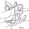
- shows a perspective view of the hearing aid housing, as seen from a back thereof, wherein the battery drawer is partly open;
- Fig. 4
- shows a side view of the battery drawer according to the disclosure;
- Fig. 5
- shows a side view of the battery drawer shown in Fig. 4;
- Fig. 6
- shows a schematic, perspective top view of the battery drawer shown in Fig. 4 and in Fig. 5,
- Fig. 7
- shows a schematic, perspective exploded view of the battery drawer shown in Fig. 6;
- Fig. 8
- shows a perspective top view of the battery drawer shown in Fig. 4, Fig. 5, Fig. 6 and Fig. 7 in an assembled configuration;
- Fig. 9
- shows a top view of the battery drawer shown in Fig. 4, Fig. 5, Fig. 6 and Fig. 7 in a configuration, in which the arm member has been removed from the battery drawer;
- Fig. 10
- shows a perspective side view of the battery drawer shown in Fig. 4, Fig. 5, Fig. 6, Fig. 7, Fig. 8 and Fig. 9 in an assembled configuration and
- Fig. 11
- shows a top view of the battery drawer shown in Fig. 4, Fig. 5, Fig. 6, Fig. 7 and Fig. 8 in a configuration, in which the arm member has been removed from the battery drawer.
DETAILED DESCRIPTION
-
The detailed description set forth below in connection with the appended drawings is intended as a description of various configurations. The detailed description includes specific details for the purpose of providing a thorough understanding of various concepts. However, it will be apparent to those skilled in the art that these concepts may be practiced without these specific details. Several aspects of the apparatus and methods are described by various blocks, functional units, modules, components, circuits, steps, processes, algorithms, etc. (collectively referred to as "elements"). Depending upon particular application, design constraints or other reasons, these elements may be implemented using electronic hardware, computer program, or any combination thereof.
-
A hearing device may include a hearing aid that is adapted to improve or augment the hearing capability of a user by receiving an acoustic signal from a user's surroundings, generating a corresponding audio signal, possibly modifying the audio signal and providing the possibly modified audio signal as an audible signal to at least one of the user's ears. The "hearing device" may further refer to a device such as an earphone or a headset adapted to receive an audio signal electronically, possibly modifying the audio signal and providing the possibly modified audio signals as an audible signal to at least one of the user's ears. Such audible signals may be provided in the form of an acoustic signal radiated into the user's outer ear, or an acoustic signal transferred as mechanical vibrations to the user's inner ears through bone structure of the user's head and/or through parts of middle ear of the user or electric signals transferred directly or indirectly to cochlear nerve and/or to auditory cortex of the user.
-
The hearing device is adapted to be worn in any known way. This may include i) arranging a unit of the hearing device behind the ear with a tube leading air-borne acoustic signals into the ear canal or with a receiver/ loudspeaker arranged close to or in the ear canal such as in a Behind-the-Ear type hearing aid, and/ or ii) arranging the hearing device entirely or partly in the pinna and/ or in the ear canal of the user such as in an In-the-Ear type hearing aid or In-the-Canal/ Completely-in-Canal type hearing aid, or iii) arranging a unit of the hearing device attached to a fixture implanted into the skull bone such as in Bone Anchored Hearing Aid or Cochlear Implant, or iv) arranging a unit of the hearing device as an entirely or partly implanted unit such as in Bone Anchored Hearing Aid or Cochlear Implant.
-
A "hearing system" refers to a system comprising one or two hearing devices, and a "binaural hearing system" refers to a system comprising two hearing devices where the devices are adapted to cooperatively provide audible signals to both of the user's ears. The hearing system or binaural hearing system may further include auxiliary device(s) that communicates with at least one hearing device, the auxiliary device affecting the operation of the hearing devices and/or benefitting from the functioning of the hearing devices. A wired or wireless communication link between the at least one hearing device and the auxiliary device is established that allows for exchanging information (e.g. control and status signals, possibly audio signals) between the at least one hearing device and the auxiliary device. Such auxiliary devices may include at least one of remote controls, remote microphones, audio gateway devices, mobile phones, public-address systems, car audio systems or music players or a combination thereof. The audio gateway is adapted to receive a multitude of audio signals such as from an entertainment device like a TV or a music player, a telephone apparatus like a mobile telephone or a computer, a PC. The audio gateway is further adapted to select and/or combine an appropriate one of the received audio signals (or combination of signals) for transmission to the at least one hearing device. The remote control is adapted to control functionality and operation of the at least one hearing devices. The function of the remote control may be implemented in a SmartPhone or other electronic device, the SmartPhone/ electronic device possibly running an application that controls functionality of the at least one hearing device.
-
In general, a hearing device includes i) an input unit such as a microphone for receiving an acoustic signal from a user's surroundings and providing a corresponding input audio signal, and/or ii) a receiving unit for electronically receiving an input audio signal. The hearing device further includes a signal processing unit for processing the input audio signal and an output unit for providing an audible signal to the user in dependence on the processed audio signal.
-
The input unit may include multiple input microphones, e.g. for providing direction-dependent audio signal processing. Such directional microphone system is adapted to enhance a target acoustic source among a multitude of acoustic sources in the user's environment. In one aspect, the directional system is adapted to detect (such as adaptively detect) from which direction a particular part of the microphone signal originates. This may be achieved by using conventionally known methods. The signal processing unit may include amplifier that is adapted to apply a frequency dependent gain to the input audio signal. The signal processing unit may further be adapted to provide other relevant functionality such as compression, noise reduction, etc. The output unit may include an output transducer such as a loudspeaker/ receiver for providing an air-borne acoustic signal transcutaneously or percutaneously to the skull bone or a vibrator for providing a structure-borne or liquid-borne acoustic signal. In some hearing devices, the output unit may include one or more output electrodes for providing the electric signals such as in a Cochlear Implant.
-
Now referring to Fig. 1, parts of a hearing aid 1 comprising a housing 2 and a battery drawer 3 is illustrated. The battery drawer 3 is connected to the housing 2 through a joint structure 31, which is configured to connect the battery drawer 3 to a part of the housing 2 allowing a rotation of the battery drawer 3 in relation to the housing 2. As will be elaborated on in more detail in the following, the battery drawer furthermore comprises a compartment 5, which is shaped in the form and configured to receive a battery. As illustrated in Fig. 1 the battery drawer 3 in addition comprises an arm member 4, which are removable attached to the battery drawer 3. The removable attachment of the arm member 4 to the battery drawer 3 will be explained in more detail in the following.
-
As shown in Fig. 1, the arm member 4 comprises one or more engagement structures 18, 19, 20, which are configured to engage with a locking structure 21 of the housing of the hearing aid. This locking structure 21 is best illustrated in Fig. 2, which show that the housing 2 is configured with a protrusion inside the interior of the hearing aid housing, with which protrusion (i.e. locking structure) 21 the engagement structures 18, 19, 20 may attach.
-
The attachment between the arm member 4 and the housing is best illustrated in a combined understand of Figures 2 and 3. Figure 3 illustrates the battery drawer 3 in a partly open position, where the engagement structure 19 is at least in a position there the engagement structure 19 is not connected with the locking structure 21 in the housing. It is seen that the engagement structures 20 and 18, which forms part of the arm member 4 together with the engagement structure 19 is partly engaged in the locking structure 21 of the housing. Accordingly, the battery drawer 3 may be positioned in a first open position, where the engagement structures 18, 19, 20 are all disengaged from the housing 21, and a second partly closed position, wherein the engagement structure 18, 20 are engaged into the locking structure 21 of housing as shown in Fig. 3. In a fully closed position, which also provides an "on-state" of the hearing aid, the battery drawer 3 has been positioned into the hearing aid housing 2, in a manner by which the engagement structure 21 clicks into engagement with the locking structure 21 of the housing.
-
Thus, it is apparent that the engagement structure upon the opening and closing of the battery drawer 3 will be prone to wear and tear which may cause the engagement structure to break, which leads to a dysfunctional battery drawer.
-
Therefore, by providing the arm member 4 as a detachable part of the battery drawer 3, merely the arm member 4 needs to be changed when the engagement structures become dysfunctional due to wear and tear.
-
Therefore, in more detail, the battery drawer 3 comprises an arm member 4, which in case of dysfunctionality thereof can be removed from the battery drawer 3, such that a new arm member may be inserted, as illustrated in Figure 7, where the arm member 4 may be removed from and inserted into the battery drawer 3 in the direction of the dotted line shown in Fig. 7.
-
Accordingly, the battery drawer 3 and the relation with the arm member 4 will be described in the following. Referring initial to Fig. 4 a schematic, perspective top view of a battery drawer 3 according to an embodiment is illustrated. The battery drawer 3 comprises a hinge assembly 34 shaped to be mechanically attached to a corresponding receiving joint structure 31 of the hearing aid housing (shown in Fig. 1). The hinge assembly 34 comprises a semi-cylindrical inner structure configured to receive a cylindrical shaft 36 arranged next to the first end of the attachment structure 34. The cylindrical shaft 26 is intended to connect the hinge assembly to the joint structure 31 of the housing structure.
-
As illustrated in Fig. 4, the battery drawer 3 comprises in a similar end as the hinge assembly, an arced support arm 44 formed as a section of a cylinder configured to receive a battery (marked as the dotted line in Fig. 4) to be inserted into the battery drawer 3. The arced support arm 44 connects with the hinge assembly 34 through a support 46, which extend from a surface of the arced support arm 44 towards the hinge assembly 34. In this way the arced support arm 44 is supported to as to assist in retaining the battery in the compartment 5 of the battery drawer 3.
-
In the opposite end of the cylindrical support arm 44 and the hinge assembly 34, the battery drawer 3 is as illustrated configured with the previously described detachable arm member 4. The arm member 4 comprises the first engagement structure 18, the second engagement structure 20 and a slit 38 provided there between. The curved surface 32 (inside portion) of the first engagement structure 18 and the second engagement structure 20 extends along a section of the just mentioned cylinder configured to receive a battery to be inserted into the battery drawer 3. Accordingly, both the arced support arm 44 and the first and second engagement structures 18, 20 of the arm member 4 constitute part of a battery holding structure 42, when the arm member 4 configured to retain the battery once inserted into the battery drawer 3. The inside portion of the second engagement structure 20 extends parallel to the inside portion of the first engagement structure 18.
-
Referring now to Fig. 7, the arm member 4 and the battery drawer 3 is illustrated an exploded view. Here it is seen that the arm member 4 comprises an attachment structure 12 which is configured to protrude axially from a side of the base 23 of the arm member. That is the protrusion extends from a side of the base 23 along a longitudinal axis of the base 23. As can be seen in Fig. 7, the attachment structure 12 may be formed as a cross. The attachment structure 12, is configured as a protruding structure to allow the arm member to engage with corresponding receiving structure 10 of the battery drawer 3. Accordingly, when the arm member 4 is inserted into the battery drawer 3, the attachment structure 12 engages into the receiving structure 10 formed on a second side 28 of the battery drawer 3, as seen on at least Fig. 6.
-
Thus, as may be seen in Figs 5 and 6, the battery drawer 3 comprises a first side 26 and a second opposite side 28, where the first side 26 is configured to receive the base 23 of the arm member 4, so as to "slide" the base 23 of the arm member along a width Wb of the battery drawer 3 is indicated, from the first side 26 to the receiving structure 10 on the second side of the batter drawer. Accordingly, the arm member 4 extends between first side 26 and the second side 28 of the battery drawer. As is more clearly indicated in Fig. 5, the first side 26 of the battery drawer comprises an opening 24 into which the base 23 of the arm member is inserted. The outer contour of the base 23 of the arm substantially aligns with the opening such that no protrusion is present on the first side 26 of the battery drawer, when the arm member 4 is inserted therein.
-
The construction of the battery drawer is shown in more detail in Fig. 6. Here it is seen that the battery drawer 3 comprises a first support structure 22 configured to abut a portion of the cylindrical outer surface of a battery. The battery drawer 3 moreover comprises a second support structure 22' configured to abut a portion of the plane outer surface of the battery and hereby prevent the battery for being moved further in the axial direction towards the first side 26.
-
To ensure that the arm member 4 may be inserted correctly into the battery drawer 3, the battery drawer 3 is configured with a track structure 6, which is best illustrated in Figs 7 and 9. Here it is seen how the track structure 6 formed in the battery drawer 3 is configured to receive the base 23 of the arm member 4 along the width of the track structure 6. That is the arm member 4 comprises a slide structure 8 extending along the longitudinal axis X of the arm member 4. The slide structure 8 is configured to substantially form the base 23 of the arm member 4, wherein the base 23 is configured to be inserted into the track structure 6 to fill the track structure 6 from the first side 26 towards the second side 28. The track structure 6 has a longitudinal axis Y, along which the slide structure 8 is configured to be moved in order to detachably attach the arm member 4 to the battery drawer 3.
-
It can be seen that the width Wb of the battery drawer 3 corresponds to the width Wa of the arm member 4. Accordingly, the outer distal portion of the attachment structure 12 will level with the second side 28 once the attachment structure 12 has been received by the receiving structure 10 of the second side 28 of the battery drawer 3. Accordingly, as previously described with the first side 26, the second side does not have any protrusion when the arm member 4 is inserted into the battery drawer 4. That is the surface of the attachment structure 12 aligns with and are substantially flush with the first second side 28, when received in the receiving structure 10.
-
8 illustrates a view of the battery drawer 3, wherein the arm member 4 has been inserted into the battery drawer 3. As may be seen both in Fig. 8 but also in Fig. 4, it is clear that opening 24 of the battery drawer has been substantially closed off by an end of the base 23, thus the end of the base is flush with the side 26 of the battery drawer 3.
-
Furthermore, in Fig. 9 it can be seen that the track structure 6 in more detail comprises a first upper portion 14, a second upper portion 14' and a bottom portion 16. The first upper portion 14 and the second upper portion 14' protrudes from the bottom portion 16. The first upper portion 14, the second upper portion 14' and the bottom portion 16 defines a concave interior of the track structure 6. An elongated gap 40 is provided in the battery drawer 3. The gap 40 is defined by the distal end of the first upper portion 14 and the distal end of the second upper portion 14', and the gap ensures that the engagement structure 18, 20 of the arm member is able to extend from the base 23 out through the gap so as to be able to reach the locking structure 21 in the housing 2 of the hearing aid.
-
As may be seen, the arm member 4 has in Fig. 11 been fully inserted into the track structure 6 of the battery drawer 3. The breadth Bb of the gap 40 of the concave interior of the track structure 6 is indicated, andit can be seen, that the magnitude of the breadth Bb is so small that it possible to prevent the slide structure 8 of the arm member 4 to be moved in a direction perpendicular to the longitudinal axis of the slide structure 8. The breadth Bb (the closest distance between the opposing distal portions of the first upper portion 14 and the second upper portion 14') is smaller than the breadth Ba of the slide structure 8 (the largest distance between opposing sides of the slide structure 8).
-
The two upper portions 14, 14' extend from the bottom portion 16 and are angled approximately 45 degrees relative to the bottom portion 16. Accordingly, the two upper portions 14, 14' form a narrow gap 40. Thus, the upper portions 14, 14' and the bottom portion 16 constitute a locking structure of the track structure 6 preventing the arm member 4 from being displaced in directions perpendicular to the longitudinal axis of the arm member 4.
-
As used, the singular forms "a," "an," and "the" are intended to include the plural forms as well (i.e. to have the meaning "at least one"), unless expressly stated otherwise. It will be further understood that the terms "includes," "comprises," "including," and/or "comprising," when used in this specification, specify the presence of stated features, integers, steps, operations, elements, and/or components, but do not preclude the presence or addition of one or more other features, integers, steps, operations, elements, components, and/or groups thereof. It will also be understood that when an element is referred to as being "connected" or "coupled" to another element, it can be directly connected or coupled to the other element but an intervening element may also be present, unless expressly stated otherwise. Furthermore, "connected" or "coupled" as used herein may include wirelessly connected or coupled. As used herein, the term "and/or" includes any and all combinations of one or more of the associated listed items. The steps of any disclosed method are not limited to the exact order stated herein, unless expressly stated otherwise.
-
It should be appreciated that reference throughout this specification to "one embodiment" or "an embodiment" or "an aspect" or features included as "may" means that a particular feature, structure or characteristic described in connection with the embodiment is included in at least one embodiment of the disclosure. Furthermore, the particular features, structures or characteristics may be combined as suitable in one or more embodiments of the disclosure. The previous description is provided to enable any person skilled in the art to practice the various aspects described herein. Various modifications to these aspects will be readily apparent to those skilled in the art, and the generic principles defined herein may be applied to other aspects.
-
The claims are not intended to be limited to the aspects shown herein, but is to be accorded the full scope consistent with the language of the claims, wherein reference to an element in the singular is not intended to mean "one and only one" unless specifically so stated, but rather "one or more." Unless specifically stated otherwise, the term "some" refers to one or more.
-
Accordingly, the scope should be judged in terms of the claims that follow.